Pegasus II. Tripoli Level 3 Project Documentation. Brian Wheeler
|
|
|
- Sheryl Bond
- 6 years ago
- Views:
Transcription


1 Pegasus II Tripoli Level 3 Project Documentation Brian Wheeler
2 Contents: A. Design Overview B. Booster Construction C. Electronics Bay (Mechanical) Construction D. Nose Cone Construction E. Recovery System Components F. Electronics (Electrical) G. Simulations H. Parts List I. Pre-Flight Checklist J. Flight Summaries
3 A. Design Overview Pegasus II is a 38lb, 6 diameter rocket constructed with filament wound fiberglass components from Warehouse. It will generally achieve around 8,000 ft on M motors and 5,000 ft on L motors. The test flight and Level 3 certification flight will take place at Washington Aerospace Club s Fire in the Sky launch on May , 2016 The rocket s center of pressure is calculated to be 34.4 from the base. This is marked with a small hole in between the booster s rail buttons to confirm stability before flight.
4


5 B. Booster Construction Three fin slots were cut through the body tube and tail cone using a router on a plate with 4 cam rollers. Fins were first rough cut from G10 fiberglass, then trimmed straight using a router with a straight-cutting jig and a composite cutting bit Using a 3D printer, a jig was created to bevel the fins at 10 degrees while leaving thickness at the tips. This Jig was clamped onto the router base, and each fin was moved by hand against the router to create the bevel. The fins and the motor tube were then sanded to create a rough surface for epoxy adhesion.


6 To attach the first fin, 3 blocks were 3D printed to present the fin at precisely the correct elevation relative to the motor tube. High temperature Proline 4500 epoxy was used for fin tacking and fillets. For the remaining 2 fins, two alignment guides were used, cut with a laser cutter from thin plywood. Proline 4500 epoxy fillets were created using a 1 diameter PVC section. To apply masking tape for the excess epoxy, permanent marker was applied repeatedly to the PVC and rubbed along the joint to create a mark at the edge of the desired fillet. Tape was then applied at this line Around 20 minutes after each fillet was created, the masking tape was removed. 3 layers of 5.7 oz 2 2 twill carbon fiber was then applied using Aeropoxy to the fin joint area. This will ensure the fin tabs remain attached to the motor tube.


7 Rail Button mounts were created using oak with a 3 pronged #8x32 threaded insert which is mechanically prevented from escaping. Grease was applied to the rail button and machine screw, epoxy was spread over the rail button support piece, and then the rail button was screwed into place, forcing the support against the airframe ID. These three 1010 buttons are spaced at 2 ft intervals starting at 15 from the base of the rocket. Centering rings were made out of 7-ply plywood. These were rough cut with a scroll saw, then trimmed to size using an aluminum template with a router and a flush-trim bit. A bulkhead was created with a 5/16 U-bolt to connect to the recovery harness and to provide motor retention via an aluminum threaded rod connected to the forward closure. A thrust plate was machined from 7075 aluminum to transfer the motor s thrust to both the motor tube and the tail cone simultaneously. Grooves were cut to ensure mechanical bond, then the plate was


8 attached to the motor tube and the tail cone with ProLine 4500 Epoxy. The motor is retained using a 3/8 Aluminum threaded rod that connects the forward closure to the bulkhead at the top of the booster. Once the rail button mounts and centering rings were installed, the fin can assembly, airframe, and tail cone were epoxied together. Then external fillets were created.

9 Two layers of 2 2 carbon were laid tip to tip on the fins, and the setup was vacuum bagged. The final construction step for the booster was to coat the carbon with Aeropoxy Light and sand.


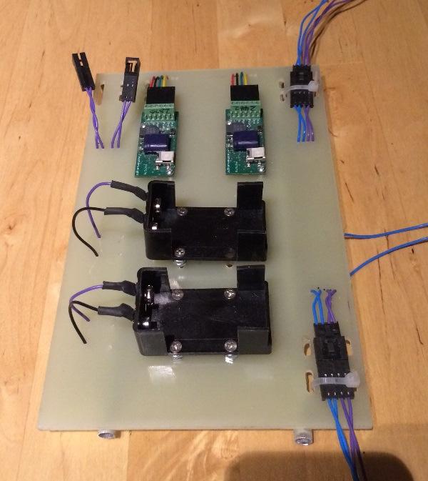
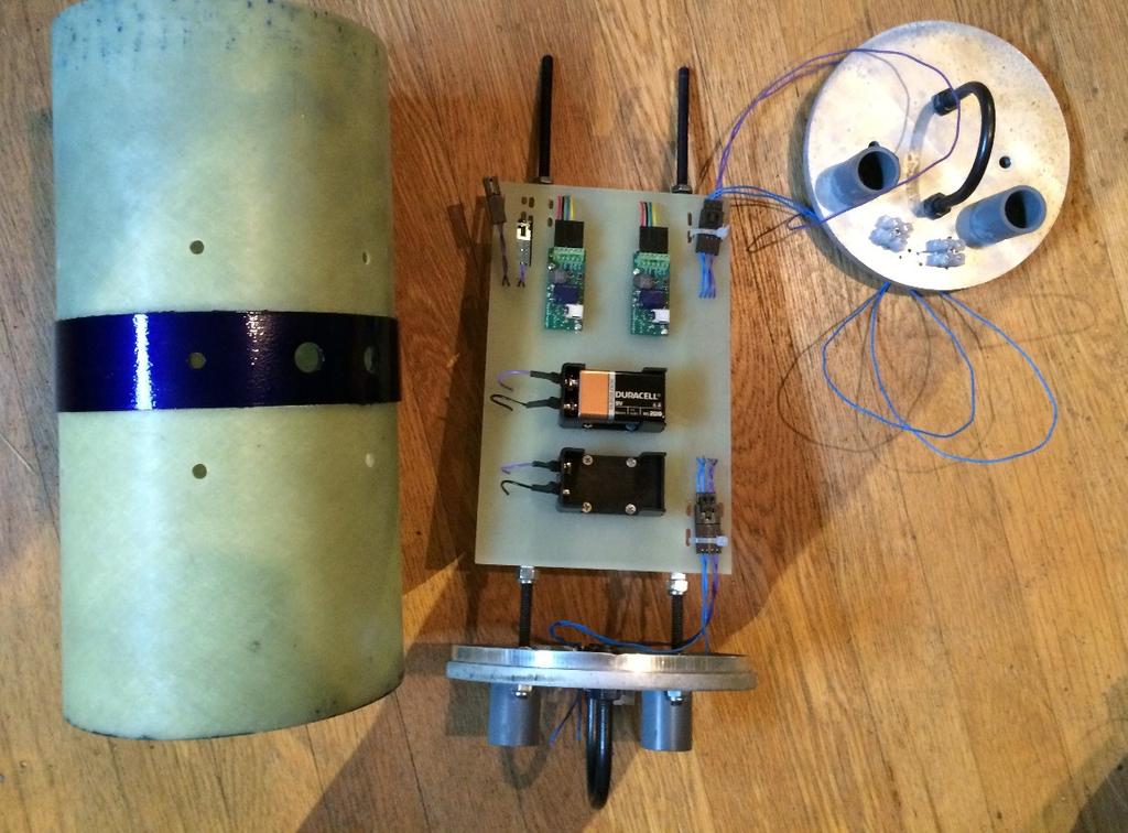
10 C. Electronics Bay (Mechanical) Construction The electronics bay bulkheads are milled from 6061 Aluminum. They are 0.3 thick, with an additional 0.3 thick shoulder to center the bulkhead in the coupler. A 1/16 Thick, Diameter O-ring seals the joint between the end of the coupler tube and the bulkhead. A switch band was epoxied in the center of the coupler which houses the electronics bay. Three ¼ vent holes were drilled around the ring, and two holes were drilled for the Missileworks switches. An additional hole was drilled for the 3 rd rail button.
11 Running the length of the electronics bay are two ¼ x20, 13 long high strength steel threaded rods, which hold the two bulkheads together and act as rails for the electronics sled. The electronics sled is created with a thick G10 fiberglass sheet, with thin walled aluminum tubing that slides over the threaded rods. 5/16 x 2 U-Bolts are attached with nylon insert nuts and o-rings to create a seal. Doghouse rocketry charge wells were attached to each bulkhead, as well as 2 pairs of screw terminals for attaching the electric matches.


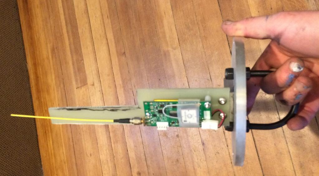
12 D. Nose Cone Construction The Nose Cone is a Warehouse 6 filament wound cone. The shoulder was attached using Aeropoxy Structural Adhesive A ring was machined with 4 x 1/4-20 mounting holes to mount the bulkplate, which attaches to the recovery harness. This ring was epoxied in place using Proline epoxy after cutting grooves into the exterior aluminum surface for adhesion. On the bulkhead, an L-bracket was machined to connect a small fiberglass board which holds the GPS transmitter

13 E. Recovery System Components 1. Drogue Chute Configuration 1. Based on the failure of the first certification attempt, the drogue in subsequent flights will be placed 1/3 of the way along the shock chord from the upper section to the booster. This should keep the two sections relatively horizontal, and at worst should keep the upper section above the booster, reducing the chance for the main to tangle when it deploys from the upper section of the rocket. 2. The Drogue Parachute is a SkyAngle 24 L3 Drogue 3. The forward and aft rocket sections are held together with 6 ft. of 1/2 tubular Kevlar for flame protection, and then 30 ft of 1 tubular nylon. The nylon was chosen because it can stretch slightly during an energetic deployment, allowing a longer deceleration for the rocket components. A 24 x24 flame protector protects the drogue. 2. Main Chute Configuration 1. The main parachute for the rocket (minus the nose cone) is a 144 Spherachute, which is rated for 30 to 54 lbs. This parachute will be stored in a deployment bag. This parachute is attached to the rocket with 6 ft. of 1/4 tubular Kevlar.Descent rate of the 32 lb airframe is 15 ft/s 2. The Nose Cone has its own 52 SkyAngle Classic II which will pull the nose cone and deployment bag away from the rocket s main parachute. Descent rate of the 6.2 lb nose is 15 ft/s 3. Black Powder Charges Based on online calculators, the ejection charges were estimated and then tested. The charges will be 4 grams for the drogue (with a 5 gram backup at a 1 second delay) and 6 grams for the main (with a 6 gram backup 100 feet delayed)


14 4. Shear Pins Three #4x40 shear pins are used to secure the booster and nose cone to the central section. 5. Rivets Six diameter click-lock shank rivets are used to secure the two middle airframe sections to the electronics bay for the duration of the flight. These are designed to be several times stronger than the shear pins. This setup functioned successfully during testing. Making a black powder ejection charge with an e-match, tape, and cling wrap. Testing the charges (video at wheelerl3.wordpress.com)


15 F. Electronics (Electrical) The rocket s electronics consist of redundant Raven Accelerometers/Altimeters each powered by a 9V battery. Doghouse wire connectors are used to connect the sled to the bulkheads and the two Missileworks rotary switches. All 4 charges are activated with General Electric ignitors from Amazon, which have been tested in the flight configuration. A schematic is shown below: All wire connections were soldered and then covered in heat shrink using a heat gun. All electrical connectors are latching and are cable tied to the board before launch. A fresh 9V battery will be used for each flight. Screw terminals are used to connect the electric matches to the system on the face of the bulkhead. A Big Red Bee 70cm GPS tracking unit is housed by itself in the nose cone, and is simply plugged into its onboard power supply before flight

16
17


18 G. Simulation Flight simulations were run with the two flight motors, a CTI Pro75 L1350 for the test flight, and a CTI Pro75 M2045 for the certification flight. The actual measured weight of 38 lb, and the measured empty CG of 53 from the rocket s base are used for the simulation. The rod length is set to be = 57.6, which is the length of the rod remaining above the central rail button. The simulation results are listed in the table below L1350 M2045 Velocity of Rail 44.7 ft/s 54.9 ft/s Apogee 4455 ft 8237 ft Max Velocity 568 ft/s 900 ft/s Max Accel 6.68 G 10.5G
19 H. Parts List A. Booster Part No A1 1 A2 1 A3 1 Qty Description Vendor 24" Long 6" G12 airframe 12" long 6" G12 Coupler 6" Nose Cone cut to 14.25" Length and slotted for 3 fins to create a 6" to 4.2" Tail Cone Warehouse Warehouse A4 1 Aluminum 4.1" to 3" thrust plate Custom A5 1 7 ply, 3/8" thick 3" to 6" Birch Centering Ring Custom Public Missiles / Custom Slots A6 1 7 ply, 3/8" Thick 3" to 6" Coupler Birch Centering Ring Custom A ply, 3/4" Thick 6" Coupler Bulkplate with 1/2" hole for motor retention and drilled for U-Bolt Custom A8 1 5/16" Diam by 2" ID Black Oxide U-Bolt rated at 600 lb, secured with nylon insert nuts permanently attached with JB-Weld ACE Hardware A9 3 Fins cut from " G12 12"x12" blanks Custom Composites A10 3 layers 5.7 oz Carbon from fin root to fin root across motor mount tube US Composites A11 1 Layer of 10 oz Carbon from fin tip to fin tip US Composites A12 1 Layer 5.7 oz carbon from fin tip to fin tip US Composites Rail Buttons A13 2 A14 2 #8 x 32, 1" Long Flat head machine screw 1010 delrin rail buttons Doghouse Doghouse A15 2 #8 x 32 three pronged wooden threaded insert ACE hardware A16 2 Pine carriers for rail button threads Custom Motor Retention A17 1 3/8" x 16 Aluminum threaded rod, 25" L or 10" L depending on motor McMaster A18 1 3/8" x 16 Hex Nut McMaster B. Middle Section B1 1 24" Long 6" G12 airframe B2 1 36" Long 6" G12 airfram B3 1 12" Long 6" G12 coupler Warehouse Warehouse Warehouse
20 B " Long 6" Switch Band E-Bay Bulkhead Assy Warehouse B5 2 Electronics Bay Bulkhead - Aluminum Milled Part Custom 5/16" Diam by 2" ID Black Oxide U-Bolt rated at 600 lb, secured B6 2 with nylon insert nuts McMaster B7 2 Large Charge Wells Doghouse B8 #10x24 Flat head socket cap screw Mcmaster B9 4 Terminal Strip, 2 wire Doghouse / Cut to size B10 4 #4x40 Socket Head Cap Screw, 7/16" Length McMaster Electronics Bay Internals B " Long 1/4x20 High Strength Threaded Rod McMaster B12 6 1/4x20 Nylon Insert Nut McMaster B13 4 1/4x20 Thin Nut McMaster B14 1 5" x 10" Electronics Bay Board, cut from 0.125" G10 Fiberglass Custom B15 2 Raven Altimeter Unit Featherweight B16 4 #2x56 x 0.5" machine screw McMaster B17 4 #2 x 0.125L nylon spacer McMaster B18 4 #2x56 Hex Nut McMaster B terminal connector B terminal connector B21 2 9V battery holder Dog House Dog House Dog House B22 8 #4x40 flat head machine screw, 0.5" Lenngth ACE Hardware B23 8 #4 ID Nylon spacer, 7/32 length Mcmaster B24 2 Rotary switches Missileworks B25 2 Third Rail Button #8 x 32, 1" Long Flat head machine screw Doghouse Doghouse B delrin rail buttons 2 B27 2 #8 x 32 three pronged wooden threaded insert ACE hardware B28 2 Pine carriers for rail button threads Custom Section Connectors B diameter click-lock shank rivets Mcmaster B30 6 #4x40, 5/16 Length Nylon Screws (REPLACE EACH FLIGHT) Mcmaster Seals B mm ID x 1.5mm thickness O-ring (Seals 1/4" rods) McMaster B32 8 8mm ID x 1mm thickness O-ring (Seals 5/16" threads for U-bolt) Mcmaster
21 Electronics Bay Expendables B33 4 "General Electric Igniter" (REPLACE EACH FLIGHT) Amazon B34 1 ft Saran Wrap for making ejection charges (REPLACE EACH FLIGHT) - B35 2 9V Duracell battery (REPLACE EACH FLIGHT) - B36 20 g FFFFG Black Powder for ejection charges (REPLACE EACH FLIGHT) Muzzle Loader Supply C. Nose Cone C1 1 30" Long FWFG Nose Cone Warehouse C2 1 Nose Cone Bulkplate Carrier Ring, 4.5" ID Custom C3 1 Nose Cone Bulkplate, 0.3" Thick, Aluminum Custom C4 1 5/16" Diam by 2" ID Black Oxide U-Bolt rated at 600 lb, secured with nylon insert nuts McMaster C5 1 Bulkplate to Electronics Plate L-Bracket, Aluminum Custom C6 1 Electronics Plate, 0.125" G10 Fiberglass Custom C7 4 1/4 x 20 Button Head Socket Head Cap Screws, 3/4" Length McMaster C8 1 3/8" Button Head Socket Head Cap Screw, 3/4" Length McMaster C9 2 #4x40 Button Head Machine Screws, 1" length McMaster C10 2 #4 screw x 0.5" Length Nylon Spacer McMaster C11 2 #4x40 hex nut McMaster C12 1 Big Red Bee 70cm GPS Transmitter Big Red Bee D. Recovery Drogue D1 1 SkyAngle Cert 3 Drogue (24") SkyAngle/ Wildman D2 6 ft 1/2" tubular Kevlar Top Flight Recovery
22 D lb capacity quick link McMaster D4 1 Nomex Blanket for <=8" Rockets Top Flight Recovery D5 30 ft Tubular Nylon Top Flight Recovery Main D6 6 ft 1/4" tubular Kevlar Top Flight Recovery D " Spherachutes Main Parachute Spherachutes D8 1 XXL Deployment Bag, SkyAngle D9 1 52" Classic II Parachute Skyangle D lb capacity quick link McMaster E. Adhesives Proline 4500 Epoxy Fin attachment, fillets, centering ring attachment, thrust plate attachment, coupler attachment, Nose Cone bulkplate carrier attachment Aeropoxy Structural Adhesive Booster Bulkhead attachment, switch band attachment, rail button mounts Aeropoxy Laminating Resin Used with Carbon Fiber in fin can. JB Weld Permanently secure U-bolt in inaccessable booster bulkhead Aeropoxy Light Filling rough surface of carbon and seam lines between tail cone and booster tube
23 I. Pre-Flight Checklist A. At Home Charge i. Camera ii. Radio iii. GPS Bluetooth Converter iv. Tablet v. Iphone vi. Hand Drill B. Motor Assembly 1. Build motor according to Cesaroni instructions. Use SuperLube for grease. C. Electronics Bay Prep 1. Measure the voltage of 2 new 9V batteries to confirm voltage >=9V. 2. Insert two batteries into holders, and apply 2 cable ties to each to hold in position 3. Connect the two switch connectors, the drogue charges connector (top, 4 wire), and the main charges connector (bottom, 4 wire). Use Cable ties to secure each of the 4 wire connectors 4. Ensure each of the 4 left-most screw terminals on each raven is secured to the 6-lead male terminal. The red wire should be on the LEFT. 5. Create 2 ejection charges with 4 grams of black powder and 2 ejection charges with 6 grams of black powder using saran wrap, masking tape, and an electric match. 6. On the drogue side (lower) bulkhead, screw the 4 gram black powder charges into the screw terminals and insert the charge ends into the charge wells. Tape shut 7. On the MAIN side bulkhead, screw the 6 gram black powder charges into the screw terminals and insert the charge ends into the charge wells. Tape shut. 8. Place the two large o-rings onto the e-bay bulkhead shoulders. 9. Double check that the top of the electronics sled is aligned with the up arrow on the electronics bay coupler. Slide the electronics sled, threaded rods, and lower bulkhead into the bottom of the electronics bay coupler, ensuring no wires snag. 10. Place the MAIN bulkhead with the 6 gram charges on the up end of the electronics bay coupler. Place 2 o-rings to seal the bay. Now complete the assembly by tightening 2 thin 1/4x20 hex nuts on the MAIN bulkhead side of the threaded rods, tightening the first pair against the bulkhead and the second pair against the first. 11. In a non-confined space, carefully turn on the switches, one at a time. Listen for a pair of high beeps. If OK, turn back off the switch and move on. Otherwise, disassemble and troubleshoot.
24 D. Nose Cone 1. Ensure the L-Bracket and U-bolt are tightly attached to the nose cone bulkhead. Ensure the Big Red Bee is securely attached to the carrier fiberglass panel, and that this panel is attached to the L-Bracket. 2. Connect the wire connector to power on the transmitter. 3. Secure the bulkhead to the nose cone s bulkhead carrier ring with 4 ¼ Button Head Socket Cap Screws. E. Recovery Prep 1. Booster U-Bolt: The 30 length of Tubular Nylon should be attached with a figure eight knot. The 24 Cert 3 Drogue should be attached with a quick-link, tightened sharply. Pull test the knot and inspect for 10 strands. 2. Drogue Central Connection (Quick-Link): The opposite end of the 30 of Tubular Nylon should be attached with a figure eight knot. The 6 of ½ Kevlar, with the parachute protector somewhere along the length, should also be attached with a figure eight knot. The quick-link should be tightened sharply. Pull test both knots and inspect for 10 strands. 3. Drogue Electronics Bay U-Bolt: The 6 of ½ Kevlar should be attached with a figure eight knot. Pull test the knot and inspect for 10 strands. 4. Main Electronics Bay U-Bolt: The 6 of ¼ Kevlar should be attached with a figure eight knot. Pull test the knot and inspect for 10 strands. Place the main chute protector along this Kevlar. 5. Main Chute Connect: At the far end of the 6 of ¼ Kevlar, the main parachute s shroud line loop should be attached with a figure eight knot. Pull test the knot and inspect for 10 strands. Place the main chute protector along this Kevlar. 6. Nose Cone U-Bolt: The deployment bag s nylon tail should be attached with a quicklink. The Sky Angle 52 Classic II parachute should be attached with a second quick-link. The 2 quick link should be tightened sharply. F. Rocket Assembly 1. Install motor with the threaded rod extending from the forward closure. Use a 3/8 nut at the forward bulkhead to secure the motor from the front, and use a second nut to prevent loosening. 2. Center Section: Double check e-match connections and shock chord connections with figure 8 knots. Then slide the 2 mating tubing sections onto the electronics bay assembly. Secure each with 6 black plastic rivets. Sorry again about the flames being upside-down A small hole can be used to align to the rail button for proper clocking. 3. Booster Section: Double check the kevlar to nylon knots, the drogue to kevlar knot, and the kevlar to booster knot. Slide center section onto booster and secure with 3 #4 shear pins
25 4. Nose Cone: Double check the drogue to nose cone connection, and Nose Cone chute to Nose Cone connection. Slide the nose cone onto the rocket and secure with 3 #4 shear pins G. Last Checks 1. Measure the center of gravity of the rocket. If this is not >6 forward of the CP marking hole, DO NOT FLY. 2. Turn on the Nexus Tablet and check the radio link with the rocket. Turn on the navigation app on the Iphone. 3. Fill out flight card. Calm down. Double Check that the rocket electronics are OFF 4. Strip igniter leads. Twist lightly together and tape to rocket 5. Bring these items along with the rocket i. Camera ii. Igniter iii. Masking Tape iv. Flat Head Screw Driver for Electronics Switch. v. Phillips Head Screw Driver to adjust 3 rd Rail Button vi. Hand Held Radio with Bluetooth Converter vii. Tablet viii. Iphone ix. Flight Card H. At Pad 1. Load rocket and raise rail 2. Insert igniter into motor and tape into place 3. TURN ON ELECTRONICS. Listen for 2 high pitched beeps on each. If not the case, DO NOT FLY. 4. Test control system leads for sparking. If OK, attach to igniter leads.


26 J. Flight Summaries First flight: CTI L1350 C-Star This was a flawless flight to 4794 ft, according to the Raven altimeter. Max velocity was 537 ft/s and max acceleration was 8.4 g s. The second picture illustrates the configuration that caused the next flight to fail: With the drogue attached to the booster, the upper assembly hangs below. When the main deploys, it s possible for it to become tangled in the shock chord and the booster itself
 and max acceleration was 14 g s. The flight was nominal until the main parachute deployment. The chute tangled as it rose up through the shock chord, and never inflated.")

27 Second Flight: CTI M2045 Blue Streak According to the surviving Raven altimeter, this flight flew much higher than the simulation to 10,889 ft. Max Velocity was 921 ft/s (Mach 0.82) and max acceleration was 14 g s. The flight was nominal until the main parachute deployment. The chute tangled as it rose up through the shock chord, and never inflated. The rocket hit the ground hard, but the only damage was in the electronics bay, where the electronics sled broke off its rails and one of the Ravens was damaged. For subsequent flights, the drogue will be moved to 1/3 of the way along the shock chord from the upper section to the booster. Photos by Jim Wilkerson Raven altimeter data plot showing 10,889 ft max altitude.


28 Third Flight: CTI M1675 Pink This flight was completely successful, achieving 8100 ft in altitude and recovering without issue. As a result of this flight, I earned my Tripoli Level 3 Certification!
LEVEL 3 BUILD YELLOW BIRD. Dan Schwartz
 LEVEL 3 BUILD YELLOW BIRD Dan Schwartz This entire rocket is built using the same techniques I use for my nose cones, a central airframe tube for compression strength and rings of high compression styrofoam
Tripoli Rocketry Association Level 3 Certification Attempt
 Tripoli Rocketry Association Level 3 Certification Attempt Kevin O Classen 1101 Dutton Brook Road Goshen, VT 05733 (802) 247-4205 kevin@back2bed.com Doctor Fill Doctor Fill General Specifications Airframe:
Skill Level 3 Average Skills Needed. Made In USA. Kit #04997 Skill Level 4. Zephyr Parts List
 Kit #04997 Skill Level 4 Made In USA Zephyr Parts List Item # Item Name Qty 10137 Engine Mount Tube (AT-38/11) 1 10218 Airframe Body Tube (AT-98/18) 4" Thick Wall 1 10219 Airframe Body Tube (AT-98/18)
CRITICAL DESIGN REVIEW. University of South Florida Society of Aeronautics and Rocketry
 CRITICAL DESIGN REVIEW University of South Florida Society of Aeronautics and Rocketry 2017-2018 AGENDA 1. Launch Vehicle 2. Recovery 3. Testing 4. Subscale Vehicle 5. Payload 6. Educational Outreach 7.
Pre-Flight Checklist for SLIPSTICK III
 Advanced Planning 1 Schedule a Check that waivers are available at the intended launch site and date. b Check weather forecast for wind and temperature conditions at the site. c Have TAP members approved
Presentation Outline. # Title # Title
 CDR Presentation 1 Presentation Outline # Title # Title 3 4 5 6 7 8 9 10 11 12 13 14 15 16 17 18 19 20 21 22 23 24 25 26 Team Introduction Vehicle Overview Vehicle Dimensions Upper Body Section Payload
Illinois Space Society Flight Readiness Review. University of Illinois Urbana-Champaign NASA Student Launch March 30, 2016
 Illinois Space Society Flight Readiness Review University of Illinois Urbana-Champaign NASA Student Launch 2015-2016 March 30, 2016 Team Managers Project Manager: Ian Charter Structures and Recovery Manager:
FLIGHT READINESS REVIEW TEAM OPTICS
 FLIGHT READINESS REVIEW TEAM OPTICS LAUNCH VEHICLE AND PAYLOAD DESIGN AND DIMENSIONS Vehicle Diameter 4 Upper Airframe Length 40 Lower Airframe Length 46 Coupler Band Length 1.5 Coupler Length 12 Nose
Modified shock-cord mount and cables (cables are shown pushed into motor mount here)
") Building the Ariel Builder: Ray Wilkinson This is Ray Wilkinson's own rocket, but will mostly reside at UH, and will be used for display purposes as well as being flown. It's built from a kit made by PML
Building the Ariel Builder: Ray Wilkinson This is Ray Wilkinson's own rocket, but will mostly reside at UH, and will be used for display purposes as well as being flown. It's built from a kit made by PML
Presentation Outline. # Title
 FRR Presentation 1 Presentation Outline # Title 3 4 5 6 7 8 9 10 11 12 13 14 15 16 17 18 19 20 21 22 23 24 Team Introduction Mission Summary Vehicle Overview Vehicle Dimensions Upper Body Section Elliptical
Jordan High School Rocketry Team. A Roll Stabilized Video Platform and Inflatable Location Device
 Jordan High School Rocketry Team A Roll Stabilized Video Platform and Inflatable Location Device Mission Success Criteria No damage done to any person or property. The recovery system deploys as expected.
Electronic Deployment
 Electronic Deployment and a little bit of recovery too! By: Gerald Meux, Jr. NAR and TRA Level 3 1-3-11 8/28/2014 Electronic Deployment - Gerald Meux, Jr. 1 Table of Contents 8/28/2014 Electronic Deployment
Critical Design Review
 Critical Design Review University of Illinois at Urbana-Champaign NASA Student Launch 2017-2018 Illinois Space Society 1 Overview Illinois Space Society 2 Launch Vehicle Summary Javier Brown Illinois Space
Team Air Mail Preliminary Design Review
 Team Air Mail Preliminary Design Review 2014-2015 Space Grant Midwest High-Power Rocket Competition UAH Space Hardware Club Huntsville, AL Top: Will Hill, Davis Hunter, Beth Dutour, Bradley Henderson,
PRELIMINARY DESIGN REVIEW
 PRELIMINARY DESIGN REVIEW 1 1 Team Structure - Team Leader: Michael Blackwood NAR #101098L2 Certified - Safety Officer: Jay Nagy - Team Mentor: Art Upton NAR #26255L3 Certified - NAR Section: Jackson Model
MR-1. Please read and understand all instructions before building!
 MR-1 This kit contains all the parts necessary* to build a flying high power rocket: (1) Pre-slotted main airframe (1) Nose cone with strap (3) Fins (1) Transition (1) Airframe section 1 long (1) Piston
Close Proximity Recovery System
 CPR-MAX Close Proximity Recovery System Tired of the long walks associated with recovering high altitude rockets? So were we! That s why we developed the Close Proximity Recovery System (CPR). CPR uses
Tacho Lycos 2017 NASA Student Launch Flight Readiness Review
 Tacho Lycos 2017 NASA Student Launch Flight Readiness Review High-Powered Rocketry Team 911 Oval Drive Raleigh NC, 27695 March 6, 2017 Table of Contents Table of Figures... 9 Table of Appendices... 11
NASA - USLI Presentation 1/23/2013. University of Minnesota: USLI CDR 1
 NASA - USLI Presentation 1/23/2013 2013 USLI CDR 1 Final design Key features Final motor choice Flight profile Stability Mass Drift Parachute Kinetic Energy Staged recovery Payload Integration Interface
Flight Readiness Review
 Flight Readiness Review University of Illinois at Urbana-Champaign NASA Student Launch 2017-2018 Illinois Space Society 1 Overview Illinois Space Society 2 Launch Vehicle Summary Javier Brown Illinois
Preliminary Design Review. California State University, Long Beach USLI November 13th, 2017
 Preliminary Design Review California State University, Long Beach USLI November 13th, 2017 System Overview Launch Vehicle Dimensions Total Length 108in Airframe OD 6.17in. ID 6.00in. Couplers OD 5.998in.
Presentation 3 Vehicle Systems - Phoenix
 Presentation 3 Vehicle Systems - Phoenix 1 Outline Structures Nosecone Body tubes Bulkheads Fins Tailcone Recovery System Layout Testing Propulsion Ox Tank Plumbing Injector Chamber Nozzle Testing Hydrostatic
NASA SL - NU FRONTIERS. PDR presentation to the NASA Student Launch Review Panel
 NASA SL - NU FRONTIERS PDR presentation to the NASA Student Launch Review Panel 1 Agenda Launch Vehicle Overview Nose Cone Section Payload Section Lower Avionic Bay Section Booster Section Motor Selection
University Student Launch Initiative
 University Student Launch Initiative HARDING UNIVERSITY Flight Readiness Review March 31, 2008 Launch Vehicle Summary Size: 97.7 (2.5 meters long), 3.1 diameter Motor: Contrail Rockets 54mm J-234 Recovery
CRITICAL DESIGN PRESENTATION
 CRITICAL DESIGN PRESENTATION UNIVERSITY OF SOUTH ALABAMA LAUNCH SOCIETY BILL BROWN, BEECHER FAUST, ROCKWELL GARRIDO, CARSON SCHAFF, MICHAEL WIESNETH, MATTHEW WOJCIECHOWSKI ADVISOR: CARLOS MONTALVO MENTOR:
Overview. Mission Overview Payload and Subsystems Rocket and Subsystems Management
 MIT ROCKET TEAM Overview Mission Overview Payload and Subsystems Rocket and Subsystems Management Purpose and Mission Statement Our Mission: Use a rocket to rapidly deploy a UAV capable of completing search
1:6 BLACK BRANT II. c o s m o d r o m e r o c k e t r y
 c o s m o d r o m e r o c k e t r y 1:6 BLACK BRANT II This kit is capable of use with high thrust motors. It is therefore strongly recommended that epoxy be used throughout the construction of this kit.
Auburn University Student Launch. PDR Presentation November 16, 2015
 Auburn University Student Launch PDR Presentation November 16, 2015 Project Aquila Vehicle Dimensions Total Length of 69.125 inches Inner Diameter of 5 inches Outer Diameter of 5.25 inches Estimated mass
Bumble Bee. Please read and understand all instructions before building!
 Bumble Bee The Bumble Bee kit contains all the parts necessary* to build a flying high power rocket: (1) Pre-slotted main airframe (1) Recovery tube (1) Nose cone (3) Fins (1) Piston ejection kit: (1)
NASA USLI PRELIMINARY DESIGN REVIEW. University of California, Davis SpaceED Rockets Team
 NASA USLI 2012-13 PRELIMINARY DESIGN REVIEW University of California, Davis SpaceED Rockets Team OUTLINE School Information Launch Vehicle Summary Motor Selection Mission Performance and Predictions Structures
NASA USLI Flight Readiness Review (FRR) Rensselaer Rocket Society (RRS)
 Rensselaer Rocket Society (RRS)") 2016-2017 NASA USLI Flight Readiness Review (FRR) Rensselaer Rocket Society (RRS) Rensselaer Polytechnic Institute 110 8th St Troy, NY 12180 Project Name: Andromeda Task 3.3: Roll Induction and Counter
2016-2017 NASA USLI Flight Readiness Review (FRR) Rensselaer Rocket Society (RRS) Rensselaer Polytechnic Institute 110 8th St Troy, NY 12180 Project Name: Andromeda Task 3.3: Roll Induction and Counter
ADVANCED MODEL ROCKET
 ADVANCED MODEL ROCKET Assembly and Operation Instructions Division of RCS Rocket Components, Inc. BEFORE YOU BEGIN: COMPLETED BARRACUDA ADVANCED MODEL ROCKET 19920-3092 Rev. 8/12/04 Study the illustrations
MiG-15 ARF Assembly & Operation Manual
 INLET PREP The MiG-15 inlet system has been accurately assembled at BVM. The following steps are required by the modeler prior to installation in the model. The inlet duct system is not glued into the
LaserHawk Flying Model Rocket Instructions Designed by Matt Steele
 VEHICLE DATA SHEET Physical Data North Coast Rocketry LaserHawk Flying Model Rocket Instructions Designed by Matt Steele Parameter Dimension Length Diameter 57 (145 cm) 2.64 (6.7 cm) Weight (w/o chute)
The University of Toledo
 The University of Toledo Project Kronos Preliminary Design Review 11/03/2017 University of Toledo UT Rocketry Club 2801 W Bancroft St. MS 105 Toledo, OH 43606 Contents 1 Summary of Proposal... 6 1.1 Team
Strap-on Booster Pods
 Strap-on Booster Pods Strap-On Booster Parts List Kit #17052 P/N Description Qty 10105 AT-24/12 Slotted (Laser Cut) Tube 2 10068 Engine Mount (AT-18/2.75) Tube 2 13029 CR 13/18 2 13031 CR 18/24 4 14352
ADVANCED MODEL ROCKET. Read And Follow All Instructions
 Division of RCS Rocket Components, Inc. Assembly and Operation Instructions BEFORE YOU BEGIN: ADVANCED MODEL ROCKET COMPLETED CHEETAH ADVANCED MODEL ROCKET 19916-3092 Rev. 8/12/04 Study the illustrations
ADVANCED MODEL ROCKET
 Division of RCS Rocket Components, Inc. Assembly and Operation Instructions BEFORE YOU BEGIN: ADVANCED MODEL ROCKET COMPLETED INITIATOR ADVANCED MODEL ROCKET 19911-8091 Rev. 8/12/04 Study the illustrations
NUMAV. AIAA at Northeastern University
 NUMAV AIAA at Northeastern University Team Officials Andrew Buggee, President, Northeastern AIAA chapter Dr. Andrew Goldstone, Faculty Advisor John Hume, Safety Officer Rob DeHate, Team Mentor Team Roster
GIT LIT NASA STUDENT LAUNCH PRELIMINARY DESIGN REVIEW NOVEMBER 13TH, 2017
 GIT LIT 07-08 NASA STUDENT LAUNCH PRELIMINARY DESIGN REVIEW NOVEMBER TH, 07 AGENDA. Team Overview (5 Min). Educational Outreach ( Min). Safety ( Min) 4. Project Budget ( Min) 5. Launch Vehicle (0 min)
CNY Rocket Team Challenge. Basics of Using RockSim 9 to Predict Altitude for the Central New York Rocket Team Challenge
 CNY Rocket Team Challenge Basics of Using RockSim 9 to Predict Altitude for the Central New York Rocket Team Challenge RockSim 9 Basics 2 Table of Contents A. Introduction.p. 3 B. Designing Your Rocket.p.
HPR Staging & Air Starting By Gary Stroick
 Complex Rocket Design Considerations HPR Staging & Air Starting By Gary Stroick 1. Tripoli Safety Code 2. Technical Considerations 3. Clusters/Air Starts 4. Staging 5. Summary 2 1. Complex High Power Rocket.
EXTRA 330LX. Specifications: Code: SEA274. Graphics and specifications may change without notice. ASSEMBLY MANUAL
 ASSEMBLY MANUAL EXTRA 330LX Code: SEA274 Graphics and specifications may change without notice. Specifications: Wingspan---------------82.0 in (208.2 cm). Wing area---------------1349.4 sq.in ( 87.1 sq.dm).
COMPLETED MIRAGE ADVANCED MODEL ROCKET
 Division of RCS Rocket Components, Inc. BEFORE YOU BEGIN: Study the illustrations and sequence of assembly. The sequence of assembly is important. Review the parts list and become familiar with all parts
Auburn University. Project Wall-Eagle FRR
 Auburn University Project Wall-Eagle FRR Rocket Design Rocket Model Mass Estimates Booster Section Mass(lb.) Estimated Upper Section Mass(lb.) Actual Component Mass(lb.) Estimated Mass(lb.) Actual Component
USLI Flight Readiness Review
 UNIVERSITY OF MINNESOTA TWIN CITIES 2011 2012 USLI Flight Readiness Review University Of Minnesota Team Artemis 3/26/2012 Flight Readiness Report prepared by University of Minnesota Team Artemis for 2011-2012
SpaceLoft XL Sub-Orbital Launch Vehicle
 SpaceLoft XL Sub-Orbital Launch Vehicle The SpaceLoft XL is UP Aerospace s workhorse space launch vehicle -- ideal for significant-size payloads and multiple, simultaneous-customer operations. SpaceLoft
UC Berkeley Space Technologies and Rocketry Preliminary Design Review Presentation. Access Control: CalSTAR Public Access
 UC Berkeley Space Technologies and Rocketry Preliminary Design Review Presentation Access Control: CalSTAR Public Access Agenda Airframe Propulsion Payload Recovery Safety Outreach Project Plan Airframe
This Week. Next Week 4/7/15
 E80 Spring 2015 This Week! Transfer breadboard circuit to PC board.! Verify everything still works.! Get data logger working.! Pass off consists of: " Power PC board with data logger & start logging. "
Critical Design Review
 AIAA Orange County Section Student Launch Initiative 2011-2012 Critical Design Review Rocket Deployment of a Bendable Wing Micro-UAV for Data Collection Submitted by: AIAA Orange County Section NASA Student
Critical Design Review Report NASA Student Launch Florida International University American Society of Mechanical Engineers (FIU-ASME)
") Critical Design Review Report 2014-2015 NASA Student Launch Florida International University American Society of Mechanical Engineers (FIU-ASME) Florida International University Engineering Center College
Critical Design Review Report 2014-2015 NASA Student Launch Florida International University American Society of Mechanical Engineers (FIU-ASME) Florida International University Engineering Center College
Tacho Lycos 2017 NASA Student Launch Critical Design Review
 Tacho Lycos 2017 NASA Student Launch Critical Design Review High-Powered Rocketry Team 911 Oval Drive Raleigh NC, 27695 January 13, 2017 Table of Contents Table of Figures:... 8 Table of Appendices:...
Florida A & M University. Flight Readiness Review. 11/19/2010 Preliminary Design Review
 Florida A & M University Flight Readiness Review 11/19/2010 Preliminary Design Review 1 Overview Team Summary ~~~~~~~~~~~~~~~~~~~~~~~~~~~~~~ ~~~~~~~~ Vehicle Criteria ~~~~~~~~~~~~~~~~~~~~~~~~~~~~~~ ~~~~~~~~
Project NOVA
 Project NOVA 2017-2018 Our Mission Design a Rocket Capable of: Apogee of 5280 ft Deploying an autonomous Rover Vehicle REILLY B. Vehicle Dimensions Total Length of 108 inches Inner Diameter of 6 inches
Section 13. Tail Rotor Drive. RotorWay International A600 TALON Construction Manual. Section 13. Page A
 RotorWay International Page A Tail Rotor Drive Procedures covered in this section: Install driveshafts and gearboxes; install drive belt and tensioner; fabricate and install tail rotor pitch actuator arms;
University Student Launch Initiative
 University Student Launch Initiative HARDING UNIVERSITY Critical Design Review February 4, 2008 The Team Dr. Edmond Wilson Brett Keller Team Official Project Leader, Safety Officer Professor of Chemistry
Rocket Design. Tripoli Minnesota Gary Stroick. February 2010
 Rocket Design Tripoli Minnesota Gary Stroick February 2010 Purpose Focus is on designing aerodynamically stable rockets not drag optimization nor construction techniques! Copyright 2010 by Gary Stroick
COMPLETED ASTROBEE D ADVANCED MODEL ROCKET
 Division of RCS Rocket Components, Inc. BEFORE YOU BEGIN: ADVANCED MODEL ROCKET Assembly and Operation Instructions Study the illustrations and sequence of assembly. The sequence of assembly is important.
NASA SL Critical Design Review
 NASA SL Critical Design Review University of Alabama in Huntsville 1 LAUNCH VEHICLE 2 Vehicle Summary Launch Vehicle Dimensions Fairing Diameter: 6 in. Body Tube Diameter: 4 in. Mass at lift off: 43.8
University of Illinois at Urbana-Champaign Illinois Space Society Student Launch Preliminary Design Review November 3, 2017
 University of Illinois at Urbana-Champaign Illinois Space Society Student Launch 2017-2018 Preliminary Design Review November 3, 2017 Illinois Space Society 104 S. Wright Street Room 18C Urbana, Illinois
Flight Readiness Review Addendum: Full-Scale Re-Flight. Roll Induction and Counter Roll NASA University Student Launch.
 Flight Readiness Review Addendum: Full-Scale Re-Flight Roll Induction and Counter Roll 2016-2017 NASA University Student Launch 27 March 2017 Propulsion Research Center, 301 Sparkman Dr. NW, Huntsville
SunFlower Helicopter Rocket LUNAR Build Session: 9/25/08 By Tom Desmarais
 SunFlower Helicopter Rocket LUNAR Build Session: 9/25/08 By Tom Desmarais Contents of Kit: A. 3 1/16 x1 x11 basswood rotors B. 3 1/16 x2 x2 basswood fins C. 3 1/16 x5/16 x1/2 basswood hold spacer D. 3
Georgia Tech NASA Critical Design Review Teleconference Presented By: Georgia Tech Team ARES
 Georgia Tech NASA Critical Design Review Teleconference Presented By: Georgia Tech Team ARES 1 Agenda 1. Team Overview (1 Min) 2. 3. 4. 5. 6. 7. Changes Since Proposal (1 Min) Educational Outreach (1 Min)
Northwest Indian College Space Center USLI Critical Design Review
 2012-2013 Northwest Indian College Space Center USLI Critical Design Review Table of Contents, Tables, and Figures I.0 CDR Report Summary... 1 I.1 Team Summary... 1 I.2 Launch Vehicle Summary... 1 I.2a
University Student Launch Initiative Preliminary Design Review
 UNIVERSITY OF MINNESOTA TWIN CITIES 2012 2013 University Student Launch Initiative Preliminary Design Review Department of Aerospace Engineering and Mechanics 3/18/2013 2012-2013 University of Minnesota
COMPLETED SUMO LEVEL 1 MODEL ROCKET ADVANCED HIGH POWER MODEL ROCKET ASSEMBLY AND OPERATION INSTRUCTIONS BEFORE YOU BEGIN:
 COMPLETED SUMO LEVEL 1 MODEL ROCKET ADVANCED HIGH POWER MODEL ROCKET ASSEMBLY AND OPERATION INSTRUCTIONS BEFORE YOU BEGIN: Study the illustrations and sequence of assembly. The sequence of assembly is
PROJECT AQUILA 211 ENGINEERING DRIVE AUBURN, AL POST LAUNCH ASSESSMENT REVIEW
 PROJECT AQUILA 211 ENGINEERING DRIVE AUBURN, AL 36849 POST LAUNCH ASSESSMENT REVIEW APRIL 29, 2016 Motor Specifications The team originally planned to use an Aerotech L-1520T motor and attempted four full
NASA s Student Launch Initiative :
 NASA s Student Launch Initiative : Critical Design Review Payload: Fragile Material Protection 1 Agenda 1. Design Overview 2. Payload 3. Recovery 4. 5. I. Sub-Scale Predictions II. Sub-Scale Test III.
Notre Dame Rocketry Team. Flight Readiness Review March 8, :00 PM CST
 Notre Dame Rocketry Team Flight Readiness Review March 8, 2018 2:00 PM CST Contents Overview Vehicle Design Recovery Subsystem Experimental Payloads Deployable Rover Payload Air Braking System Safety and
COMPLETED ASTROBEE D ADVANCED MODEL ROCKET ADVANCED MODEL ROCKET
 19915-1092 Rev.6/99 BEFORE YOU BEGIN: ADVANCED MODEL ROCKET Assembly and Operation Instructions COMPLETED ASTROBEE D ADVANCED MODEL ROCKET Study the illustrations and sequence of assembly. The sequence
Dassault Aviation FALCON 7 X. for Jet CAT P160. Assembly Manual. AVIATION Design
 Dassault Aviation FALCON 7 X for Jet CAT P160 Assembly Manual AVIATION Design ZI le chenet, 91490 Milly La Foret, FRANCE Tel : 33 1 64 98 93 93 Fax : 33 1 64 98 93 88 E-mail : aviation.design@wanadoo.fr
FLYING MODEL ROCKET KIT INSTRUCTIONS KEEP FOR FUTURE REFERENCE. TEST-FIT ALL PARTS TOGETHER BEFORE APPLYING ANY GLUE!
 www.estesrockets.com ESTES INDUSTRIES 1295 H Street Penrose, CO 81240 PRINTED IN CHINA EST 1247/2053 FLYING MODEL ROCKET KIT INSTRUCTIONS KEEP FOR FUTURE REFERENCE. ASSEMBLY TIP: Read all instructions
Critical Design Review Report
 Critical Design Review Report I) Summary of PDR report Team Name: The Rocket Men Mailing Address: Spring Grove Area High School 1490 Roth s Church Road Spring Grove, PA 17362 Mentor: Tom Aument NAR Number
Skill Level 3 Average Skills Needed. Skill Level 3. Ibis Parts List
 Kit #05152 Skill Level 3 Made In USA Ibis Parts List Item # Item Name Qty 10076 AT- 18/3.5" LC - Engine Mount Tube 1 10123 AT- 33/6.5" LC - Body Tube 1 10124 AT- 33/18" LC - Body Tube 1 13029 CR- 13/18
Trainer Assembly Manual
 Trainer Assembly Manual www.pilot-rc.com -Pilot Trainer- 1 -Pilot Trainer- 2 -Pilot Trainer- 3 -Preliminary i wing & stab assembly- 1-) Locate both Plywood wing joiners (Large and small one) 2-) Insert
Flight Readiness Review March 16, Agenda. California State Polytechnic University, Pomona W. Temple Ave, Pomona, CA 91768
 Flight Readiness Review March 16, 2018 Agenda California State Polytechnic University, Pomona 3801 W. Temple Ave, Pomona, CA 91768 Agenda 1.0 Changes made Since CDR 2.0 Launch Vehicle Criteria 3.0 Mission
NASA Student Launch College and University. Preliminary Design Review
 2017-2018 NASA Student Launch College and University Preliminary Design Review Institution: United States Naval Academy Mailing Address: Aerospace Engineering Department United States Naval Academy ATTN:
Madison West High School Green Team
 Madison West High School Green Team The Effect of Gravitational Forces on Arabidopsis Thaliana Development Flight Readiness Review The Vehicle Mission Performance Criteria Successful two stage flight Altitude
Statement of Work Requirements Verification Table - Addendum
 Statement of Work Requirements Verification Table - Addendum Vehicle Requirements Requirement Success Criteria Verification 1.1 No specific design requirement exists for the altitude. The altitude is a
Preliminary Design Review. Cyclone Student Launch Initiative
 Preliminary Design Review Cyclone Student Launch Initiative Overview Team Overview Mission Statement Vehicle Overview Avionics Overview Safety Overview Payload Overview Requirements Compliance Plan Team
AMWPro75 Motor Adapter Instructions
 AMWPro75 Motor Adapter Instructions This document is an addendum to the Pro75 instructions. It explains how to load Pro75 reload kits into AMW75 snap ring style motor casings using the AMWPro75 motor adapter.
Ascanius Project: MECH 401/402 Senior Capstone Experience
 Loyola Marymount University and Loyola Law School Digital Commons at Loyola Marymount University and Loyola Law School Honors Thesis Honors Program 4-21-2016 Ascanius Project: MECH 401/402 Senior Capstone
TOYOTA RAV TVIP V3
 Section I Installation Preparation Part Number: 08586-4A872 Section I Installation Preparation Kit Contents Item # Quantity Reqd. Description 1 1 Wire Harness 2 1 Status Monitor 3 1 Piezo Buzzer 4 1 V3
GENUINE PARTS INSTALLATION INSTRUCTIONS
 GENUINE PARTS INSTALLATION INSTRUCTIONS 1. 2. 3. 4. DESCRIPTION: APPLICATION: PART NUMBER: KIT CONTENTS: Accent light Kit Versa Note 999F3 4Z000 - Accent Lighting Kit. 999Q9 AY000 - Accessory Service Connector
ZENITH 601, VLS INSTALLATION
 ZENITH 601, VLS INSTALLATION 09/99 DRWG. 6500-A READ INSTRUCTIONS COMPLETELY BEFORE BEGINNING INSTALLATION! The BRS installation for your Zenith 601 was designed to provide a high probability of the aircraft
INSTALLATION INSTRUCTIONS Mitsubishi Lancer Evolution VIII / IX Fuel Surge Tank Kit Document#
 d INSTALLATION INSTRUCTIONS Mitsubishi Lancer Evolution VIII / IX Fuel Surge Tank Kit Document# 19-0077 Brie Tech Support: info@radiumauto.com CAUTION: Exercise extreme caution when working with the fuel
Northwest Indian College Space Center USLI Post Launch Assessment Review
 Northwest Indian College Space Center USLI Post Launch Assessment Review 2012-2013 Table of Contents I. Team Summary... 1 Team Name: Northwest Indian College RPGs... 1 II. Launch Vehicle Summary... 1
PARACHUTE INSTALLATION MANUAL BRS SP P & M Aviation Quik & Quik GT 450 Trike Aircraft. Abstract
 Ballistic Recovery Systems, Inc. 300 Airport Rd South Saint Paul MN 55075-3551 USA www.brsparachutes.com Voice: 651-457-7491 FAX: 651-457-8651 PARACHUTE INSTALLATION MANUAL BRS-6 1050 SP P & M Aviation
University of Notre Dame
 University of Notre Dame 2016-2017 Notre Dame Rocketry Team Critical Design Review NASA Student Launch Competition Roll Control and Fragile Object Protection Payloads Submitted January 13, 2017 365 Fitzpatrick
PARACHUTE INSTALLATION MANUAL BRS 1350 HS FLIGHT DESIGN GmbH, CTLS. Abstract
 Ballistic Recovery Systems, Inc. 380 Airport Rd South Saint Paul MN 55075-3551 USA www.brsparachutes.com Voice: 651-457-7491 FAX: 651-457-8651 PARACHUTE INSTALLATION MANUAL BRS 1350 HS FLIGHT DESIGN GmbH,
Student Launch. Enclosed: Preliminary Design Review. Submitted by: Rocket Team Project Lead: David Eilken
 University of Evansville Student Launch Enclosed: Preliminary Design Review Submitted by: 2016 2017 Rocket Team Project Lead: David Eilken Submission Date: November 04, 2016 Payload: Fragile Material Protection
AKRONAUTS. P o s t - L a u n c h A ss e s m e n t R e v i e w. The University of Akron College of Engineering. Akron, OH 44325
 AKRONAUTS Rocket Design Team Project P o s t - L a u n c h A ss e s m e n t R e v i e w The University of Akron College of Engineering 302 E Buchtel Ave Akron, OH 44325 NASA Student Launch Initiative April
Turbinator-2 Build Manual
 Turbinator-2 Build Manual Thank you for your purchase of the Turbinator-2 sport jet by Boomerang RC Jets. This RC Jet IS NOT A TOY and should only be flown and operated by experienced RC Turbine Pilots.
Slipstick III Level 3 Certification
 Slipstick III Level 3 Certification Table of Contents Build Summary 3 Tap Pre-Flight Data Capture Form (M1315W) 4 TRA Level 3 Filing Instructions 5 TRA TAP Pre-Flight Review Checklist 6-7 NAR High Power
Instruction Manual book
 book SPECIFICATION Wingspan : 1,450 mm 57.09 in. Length : 1,200mm 47.24in. Weight : 3.1 kg 6.82 Lbs. Radio : 05 channels. Servo : 07 servos. Engine : 61-75 2 stroke. 91 4 stroke. Made in Vietnam. This
SCION xd INTERIOR LIGHTING UPGRADE Preparation
 Preparation Part Number: PTS21-52085 Light Guide Kit Contents Item # Quantity Reqd. Description 1 1 Controller Board, 4 color programmed w/ Bracket 2 1 RGB, LED Engine wire harness 3 2 14mm Light Rod,
TOYOTA LAND CRUISER 2003 DVD VES
 LEXUS LX470 Section I Installation Preparation Part Number: PT296 6002D 03/16 (LC) PT296 6002L 03/16 (LX) Section I Installation Preparation Kit Contents Item # Quantity Reqd. Description 1 1 FPD Assembly
INSTALLATION INSTRUCTIONS
 Rear Vision System Tailgate Emblem Camera Aftermarket Display 2009-Current Ford F-150 and 2010-Current Super Duty (Kit part number 1008-6509) Kit Contents: Tailgate Emblem Mount with Camera Chassis Harness
SERVICE BULLETIN. Fuselage Tail Cone Damage
 Fuselage Tail Cone Damage It has come to our attention that a number of Sportsman tailwheel installations have resulted in crushed and/or delaminated fuselage laminates near the aft tailwheel bracket.
NASA Student Launch W. Foothill Blvd. Glendora, CA Artemis. Deployable Rover. November 3rd, Preliminary Design Review
 2017 2018 NASA Student Launch Preliminary Design Review 1000 W. Foothill Blvd. Glendora, CA 91741 Artemis Deployable Rover November 3rd, 2017 Table of Contents General Information... 9 1. School Information...