Madison West High School Green Team
|
|
|
- Camilla French
- 6 years ago
- Views:
Transcription

1 Madison West High School Green Team
2 The Effect of Gravitational Forces on Arabidopsis Thaliana Development Flight Readiness Review
3 The Vehicle
4 Mission Performance Criteria Successful two stage flight Altitude of one mile reached accurately Successful recovery of both stages Payload not damaged Successful collection of acceleration profile
). A 3D model of the rocket.")

5 Vehicle Design A Rocket design drawing with CP and CG marked (sustainer CP: 59 inches, liftoff CP: 95 inches (from the tip of the nosecone)). A 3D model of the rocket. The red sections indicate where the electronics will be located. The payload will be placed in the green sections. The recovery systems for both stages are above the payload in each stage to allow each stage to descend in the upside up manner.
6 Changes to Design 6 fins for the booster (to move the CP down and eliminate need for noseweight) Longer booster (to make enough space for recovery subsystem) Those two changes resulted in lesser sensitivity to wind speed (only 600ft difference over the mph wind speed range).
7 Overall Vehicle Scheme Sustainer High g s (35+) Supersonic Dual deployment Drogue in apogee Main at 500ft LEGEND Drogue Parachute Alt/Acc/Timer/RDAS Biological Payload Main/PYL Parachute Motors Walston TX (Tracking) Booster Low g s (5-10) Single deployment Timed staging Timed deployment
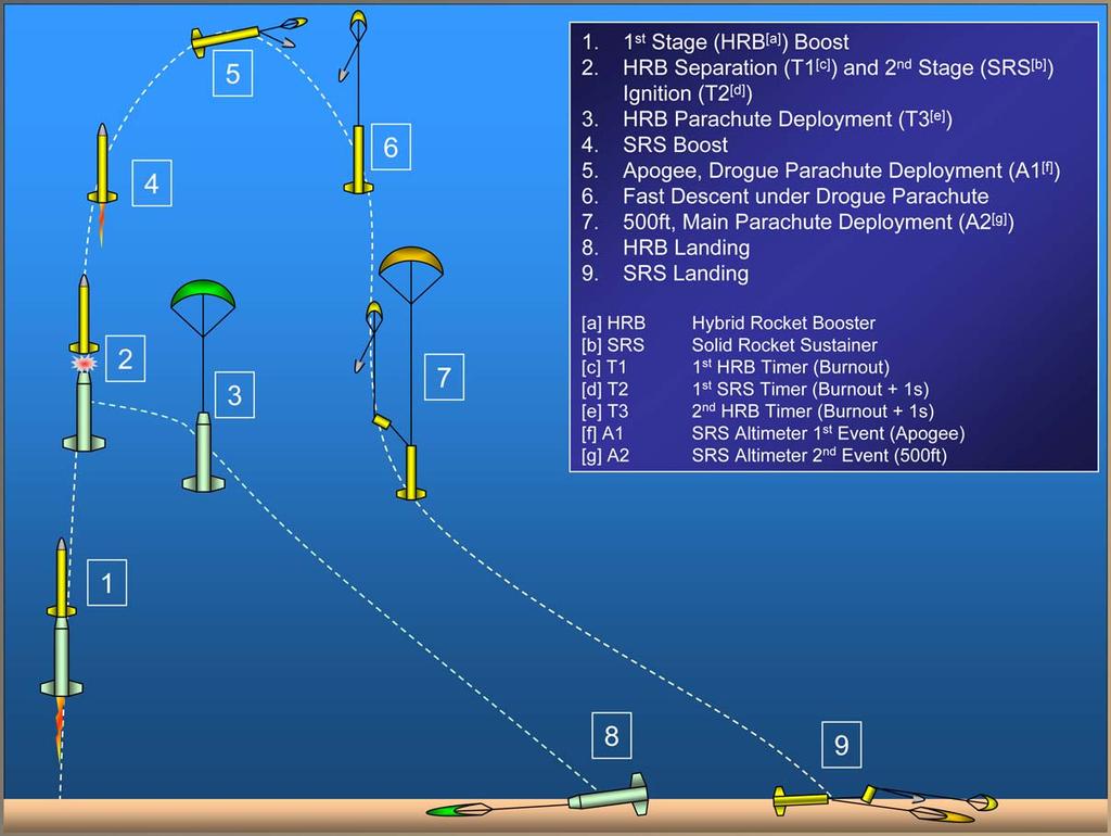
8 Flight Sequence Flight Sequence

9 Update Drawing Stage Coupling Transition Legend 4. Timer for stages separation 1. Stage Coupling Tube 5. Charge for separation 2. Motor Mount for second stage 6. Timer for 2 3. Centering Rings nd stage ignition 7. Igniter for 2 nd stage

10 Electronic Bay Second Stage Electronics Bay Legend 1. Ejection Charge for drogue parachute 2. RDAS and Accelerometer 3. Primary Altimeter 4. Back-up Altimeter 5. Ejection Charge for main parachute 6. Separation Timer 7. Staging Timer
11 Verification Plan and Status V1: Integrity/robustness test V2: Low altitude test flight V3: Parachute drop test V4: Tension test V5: Prototype flight V6: Functionality test V7: Altimeter ground test V8: Radio signal test V9: Electronic deployment test V10: Ejection test V11: Computer Simulation TESTED More Work Needed
12 Verification Plan and Status C1: Body C2: Altimeter C3: Accelerometer C4: Parachutes C5: Fins C6: Payloads C7: Timers (for separation and staging) C8: Ejection charges C9: Radio beacon C10: Launch system C11: Motor mount C12: Audio tracking (screamers) Legend P: Planned tests T: In progress F: Finished tests
13 C 2 C 3 C 4 C 5 C 6 C 7 C 8 C 9 C 10 C 11 C 12 F T F F F T T T F T T F F F F Verification Matrix V V 1 V 2 V 3 V 4 V 5 V 6 V 7 V 8 V 9 V C 1 F F F T F T F F F F F F F T T F F Verification Matrix Legend P: Planned tests T: In progress F: Finished tests
14 Design at System Level Required Subsystems First Stage/Second Stage: Propulsion Structural Payload Bay Deployment Recovery Tracking System
15 Propulsion System Booster powered by a hybrid K630 motor Sustainer powered by a solid J800T motor Centered by 3 Aircraft ply-wood centering rings Secured by an active retention system (booster: quad L-clamps, L sustainer: Lock N Load Load screw-on ring)
16 Structural: Design at System Level Booster 6 6 Phenolic tube Sustainer 4 4 Fiberglassed Phenolic tube Payload Bay: Phenolic coupler tube that houses Petri dishes Sealed with plywood caps on both ends Same in both 1 st and 2 nd stage Deployment System: Booster Altimeter for parachute deployment Sustainer 500 ft main Timer for stage Separation (PerfectFlite( PerfectFlite) Two dual event altimeters (PerfectFlite, one as backup) Timer for motor ignition (PerfectFlite( PerfectFlite)
17 Tracking and Launch Systems Tracking: Walston radio beacon Walston Beacon Receiver (ICOM) Walston Yaggi Antenna (3 elements) Two 140dB screamers Launch System: Ground support equipment for the Hybrid Motor System Launch rail (144 inches long)
18 Recovery System Single deployment system for first stage Dual deployment system for second stage Parachute Size (in) Descent Rate (fps) Weigh t (lbs) Ejection Charge (g FFF BP) First Stage Main w/piston Second Stage Drogue w/o piston Second Stage Main+Drouge w/piston
19 Simulation Results With K630/J800T Wind Speed (mph) Apogee (ft) Max Accel (gee's) Max Velocity (mph) Ballast in second stage (lbs) Stability Margins (2 nd Stage/ 1 st Stage) / / / / /6.45 According to our preliminary results (described in the payload section), 15g stress will be fully sufficient to cause visible changes in the growth of plants. Thus, the rocket does not need to reach the maximum acceleration for the experiment to succeed and we can ballast the sustainer to reach the target altitude.
20 Flight Profile Simulations Simulated acceleration profile for both stages
21 Flight Profile Simulations Re: [ROCKET CLUB: SLI2006] CDR Presentation Reminder Altitude vs. Time (wind speed = 10 mph, ballast weight = 6.5 lbs., first stage motor: K630, second stage motor: J800T)
22 Scale Model Test Flight Results Stable flight of the whole rocket (1:2.6 scale model used). The rocket flies straight even at 15mph wind with the CG located one body diameter above the 2/3 of the booster. Electronic second stage ignition still under development. We will use the PerfectFlite timer with a G-switch G and as of now, we have successfully tested the timer during a single stage flight. A special homemade low resistance igniter will be used to ignite the second stage.
23 Launch Risk Plot Problem Rocket doesn t stage Faulty Design unstable rocket Faulty Design structural failure First Stage Failure rocket doesn t ignite Result Second half of experiment is not carried out. Unsuccessful flight. Rocket disintegrates. Nothing happens. Mitigation We will do extensive testing of staging mechanisms during prototype and test flights We are doing computer simulations, low altitude flights, and prototype flights to make sure that the rocket is stable Sturdy materials (Kevlar, fiberglass, epoxy, etc.) that can sustain the stresses of the flight will be used. We use the igniters and motors properly so they do ignite.
24 Launch Risk Plot Launch failure launch rod malfunction Staging Failure catastrophic motor malfunction Recovery Failure parachutes fail to deploy or become tangled Transportation rocket is damaged during transportation Stage Separation Failure- Second stage does not separate from first stage Rocket leaves launch pad at an undesired angle. Rocket explodes. (Severe damage to the rocket and motor casing.) Ballistic fall of rocket and/or payload. Possible aberrations in launch, flight, or recovery First Stage is severely damaged. The plants are destroyed due to exposure to heat. Launch rod will be leveled, lubricated, and secured to a stable surface. Motors are properly stored and used. Parachute will be properly prepared and installed before the launch. Rocket will be properly packaged for transportation and inspected carefully before the launch. The stages will be attached loosely so that they can separate easily.
25 Launch Risk Plot Timers Do Not Initiate Reaction at the Proper Time Rocket is Carried off by Strong Wind Parachute is Tangled RDAS Failure Stages do not separate and/or parachutes/ drogue do not deploy. Rocket is lost. Mission failure. Unsafe landing of rocket. We would have no acceleration data. Rigorous tests of the timers accuracy will be performed during test flights. A tracking system will be used to locate the rocket. Radio beacon and screamers provide help in finding the rocket. Parachute shock cords will be carefully folded and inserted to prevent entanglement. Test RDAS during test flights and prior to launching to ensure that it is functioning properly before being inserted in the rocket. Insert fresh batteries prior to launch.
26 Payload Integration Payload consists from stacks of Petri dishes housed in a coupler tube. The payload fits snugly in the second stage 4 4 body. The first stage body is larger and 4 4 payload housing will be centered inside the tube by two centering rings. The electronics will be housed in standard e-e bays built out of a coupler tube and plywood caps.
27 Final Assembly Procedures 1. Check structural integrity of rocket 2. Attach parachutes to shock cords and attach shock cords to rocket sub assemblies 3. Assemble and insert the first payload into the first stage assembly 4. Insert parachutes into the first stage assembly 5. Assemble and insert the second payload into the second stage assembly 6. Insert parachutes into the second stage assembly 7. Assemble the rocket 8. Assemble the re-loadable motor 9. Insert and secure motor into the motor mount
28 First Stage Final Assembly Procedures 1. Load the payload capsule gently into the first stage body tube. 2. Verify that the first stage electronics (MAWD altimeter) is functional and have the correct settings and disarm electronics. 3. An adult will prepare an ejection charge for the electronic deployment of the first stage parachute. 4. Attach the ejection charge to electronics bay (e-bay) terminal. 5. Insert first stage e-bay e on top of payload with the e-bay e terminal and ejection charge on top. 6. Place the rest of the first stage body tube on the e-bay e and secure the e-bay e to the first stage body with screws. 7. Attach the first stage parachute s s shock cord to the hook on the e-bay, e insert the shock cord in the body tube in the proper manner and place folded first stage parachute on top.
29 Second Stage Final Assembly Procedures 1. Load the payload capsule into the upper stage body tube. 2. An adult will prepare an ejection charge with two electronic matches and put them in the rocket with their wire hanging out of the tube. 3. Attach shock cord to the top of the payload capsule, insert the cord in the proper manner, and place the second stage main parachute on top of the shock cord and ejection charge. 4. Verify the electronics (RDAS, altimeters, and timer) are functional nal and have the correct settings and disarm electronics. 5. An adult will prepare another ejection charge with two electronic c matches. 6. Attach one wire from each ejection charge to each altimeter. 7. Place the e-bay e onto the second stage body tube with the second ejection charge and the terminal on top. 8. Attach the drogue parachute shock cord to the hook on the e-bay. e 9. Put in the parachute in the proper manner. 10. Put on the nosecone.
30 Propulsion Systems Motor Preparation The motors will be prepared by Scott Goebel, our NAR mentor. The motors are solid fuel J for the upper stage and a hybrid K for the lower stage, they will be assembled and prepared in their respective motor mounts by Mr. Goebel. Throughout these motor preparation procedures, all the electronics in the rocket will be disarmed.
31 Pre-Launch Procedures 1. Place assembled rocket on launch rail 2. Active payload electronics 3. Activate altimeter to arm the ejection charges 4. Activate separation/staging electronics 5. Insert igniter into the assembled motor 6. Connect igniter to the launch system 7. Check continuity 8. Check sky for aircraft 9. Arm ignition system 10.Countdown 11.Launch
32 Post-Flight Inspection Post Flight Inspection 1. Make sure all charges have fired during flight. 2. Deactivate all electronics and sonic beacons. 3. Remove payload and check for damage. 4. Download data from the RDAS and altimeters. 5. Let the motor casings cool down and then remove from rocket, checking for damage.
33 Disarming and Re-arming Procedure 1. Remove ignition interlock to prevent accidental ignition 2. Wait designated time by HPR safety code (1 minute) 3. Disarm electronics and remove rocket from pad 4. Reinstall igniter 5. Place rocket back on pad, re-arm electronics 6. Test continuity
34 Safety NAR safety codes will be observed A safety briefing will be conducted prior each launch Procedure and safety code knowledge of all members will be test on regular basis All devices will be used in the accordance with manufacturers instructions and the operational manuals for all devices will be always on hand All electronics will have arming switches Only a certified mentor will handle the motors and ejection charges Safety equipment will be used as required
35 Major Milestone Schedule April th Two stage flight with payload, 1 mile altitude 9th 1 mile altitude test flight evaluated, improvements to design and to payload suggested 14th Design improvements and changes finished 23rd Last repairs and improvements start 28th Rocket ready for final SLI Launch May rd 7th SLI Final Meet/Launch in Huntsville

36 Any Questions?

37 The Payload

38 PAYLOAD OBJECTIVE The goal of the payload is to observe how Arabidopsis thaliana seedlings react to the strong, sudden forces associated with the acceleration of a rocket launch.
39 EXPERIMENTAL VARIABLES Six different data groups will be tested: Two genetic types of seedlings will be subjected to three different accelerations. Seed Lines Wild Type Agravitropic Acceleration Control Booster Sustainer

40 PAYLOAD OUTLINE 3-44 days post-germination Plants will be subjected to two brief jolts of acceleration during launch Short and long-term developmental effects of acceleration will be tested
41 EXPERIMENTAL RATIONALE Measures potential sources of error in launching biological payloads for space missions Conventional acceleratory-forces studies are longer-term, lower-intensity, while ours concentrates on short, high-intensity intensity force applications Genetically-designed and -altered plants are increasingly important in plant sciences
42 ROCKET DATA ACQUISITION SYSTEM Onboard RDAS unit will record acceleration profile Results will be used as estimation of acceleratory forces applied to plants Located in sustainer s s electronics bay Measures within 0.1g; however, dampening effects from agar may somewhat reduce accuracy
43 ARABIDOPSIS STRAINS Mutant strain will be agravitropic, containing a genetic alteration reducing sensitivity to gravity & acceleratory forces Other strain will be normal ( wild( type ) plants Both strains used will contain a genetic marker that facilitates root growth analysis (gene marker DR5-GUS)
44 PAYLOAD STRUCTURE 4 Petri dishes with MS Media nutrient agar 2.5 % solution, 10mL per dish 15 seeds will be placed on each dish one strain per dish Spacing between seeds will be maximized
45 RISK ASSESSMENT Significant Risks Table RISK Petri dish contamination Low seed germination rate Traumatic damage to seedlings during flight MITIGATION Aseptic technique Preparation of redundant dishes Sturdy construction of seed housings
46 PAYLOAD BAY STRUCTURE EXPLODED VIEW Bulkhead Single Petri dish ASSEMBLED VIEW
47 OVERALL PAYLOAD STRUCTURE PAYLOAD LOCATION LEGEND Petri dishes containing both strains of Arabidopsis will be placed in three locations. Sustainer Payload Section (~40g) Booster Payload Section (7g) Control Plants (non-flying) PLANT STRAINS Unaltered Plants Agravitropic Plants
48 PAYLOAD SUCCESS CRITERIA CHECKLIST Survival rate of at least 50% RDAS records accurate data Each stage reaches distinct acceleration Petri dishes remain sterile, undamaged Integration modules remain intact

49 APPROACH TO WORKMANSHIP Aseptic technique Contaminant prevention Close supervision


50 RESULTS ANALYSIS TECHNIQUE 1/3 MICROSCOPIC ANALYSIS Microscopic root analysis will be employed to obtain a detailed picture of root structure and discern the presence of traumatic damage to cells. We will use standard light microscopes as well as high- resolution dissecting scopes (on loan from the University of Wisconsin).
51 RESULTS ANALYSIS TECHNIQUE 2/3 GENE MARKER ANALYSIS When a stain is applied to the plants, cells containing the genetic marker DR5-GUS are identified. These cells are root growth promoters called auxins, allowing us to visually track root growth under a dissecting scope. Blue stain applied

52 RESULTS ANALYSIS TECHNIQUE 3/3 LONG-TERM GROWTH ANALYSIS Post-launch, approximately 1/3 of the seeds from each strain and section will be grown to maturity. After they reach the maximum development possible within the Petri dishes, they will be transferred to nutrient-enriched enriched soil. Frequent observations, comparing each type of plant to the control, will be made in order to track any alterations caused by the launch.

53 PLANT GROWTH PROCEDURES One week prior to launch, 8 dishes each of wild type and agravitropic seeds will be plated with 15 seeds After growing under lights until the launch date, the 12 healthiest dishes will be installed in the integration modules Post-launch, all dishes will be transferred back to growing conditions Schematic of booster integration module
54 MARCH 25 TEST FLIGHT Sustainer was flown with J800T engine Four Petri dishes of 20 wild-type plants each were prepared 5 days prior to launch Two dishes remained on ground as controls, two were flown Sustainer reached 37.5g (barometric data) Payload was recovered successfully


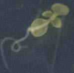
55 MARCH 25 TEST FLIGHT FLOWN PLANTS CONTROL PLANTS


56 PAYLOAD TEST FLIGHT SYNOPSIS Launched one-week week-old Arabidopsis Extremely harsh stress Caused visible duress Discerned with surprising promptness

57 Any Questions?
Statement of Work Requirements Verification Table - Addendum
 Statement of Work Requirements Verification Table - Addendum Vehicle Requirements Requirement Success Criteria Verification 1.1 No specific design requirement exists for the altitude. The altitude is a
FLIGHT READINESS REVIEW TEAM OPTICS
 FLIGHT READINESS REVIEW TEAM OPTICS LAUNCH VEHICLE AND PAYLOAD DESIGN AND DIMENSIONS Vehicle Diameter 4 Upper Airframe Length 40 Lower Airframe Length 46 Coupler Band Length 1.5 Coupler Length 12 Nose
Jordan High School Rocketry Team. A Roll Stabilized Video Platform and Inflatable Location Device
 Jordan High School Rocketry Team A Roll Stabilized Video Platform and Inflatable Location Device Mission Success Criteria No damage done to any person or property. The recovery system deploys as expected.
Critical Design Review
 Critical Design Review University of Illinois at Urbana-Champaign NASA Student Launch 2017-2018 Illinois Space Society 1 Overview Illinois Space Society 2 Launch Vehicle Summary Javier Brown Illinois Space
Flight Readiness Review
 Flight Readiness Review University of Illinois at Urbana-Champaign NASA Student Launch 2017-2018 Illinois Space Society 1 Overview Illinois Space Society 2 Launch Vehicle Summary Javier Brown Illinois
Presentation Outline. # Title # Title
 CDR Presentation 1 Presentation Outline # Title # Title 3 4 5 6 7 8 9 10 11 12 13 14 15 16 17 18 19 20 21 22 23 24 25 26 Team Introduction Vehicle Overview Vehicle Dimensions Upper Body Section Payload
Presentation Outline. # Title
 FRR Presentation 1 Presentation Outline # Title 3 4 5 6 7 8 9 10 11 12 13 14 15 16 17 18 19 20 21 22 23 24 Team Introduction Mission Summary Vehicle Overview Vehicle Dimensions Upper Body Section Elliptical
Illinois Space Society Flight Readiness Review. University of Illinois Urbana-Champaign NASA Student Launch March 30, 2016
 Illinois Space Society Flight Readiness Review University of Illinois Urbana-Champaign NASA Student Launch 2015-2016 March 30, 2016 Team Managers Project Manager: Ian Charter Structures and Recovery Manager:
University Student Launch Initiative
 University Student Launch Initiative HARDING UNIVERSITY Flight Readiness Review March 31, 2008 Launch Vehicle Summary Size: 97.7 (2.5 meters long), 3.1 diameter Motor: Contrail Rockets 54mm J-234 Recovery
NASA USLI PRELIMINARY DESIGN REVIEW. University of California, Davis SpaceED Rockets Team
 NASA USLI 2012-13 PRELIMINARY DESIGN REVIEW University of California, Davis SpaceED Rockets Team OUTLINE School Information Launch Vehicle Summary Motor Selection Mission Performance and Predictions Structures
CRITICAL DESIGN REVIEW. University of South Florida Society of Aeronautics and Rocketry
 CRITICAL DESIGN REVIEW University of South Florida Society of Aeronautics and Rocketry 2017-2018 AGENDA 1. Launch Vehicle 2. Recovery 3. Testing 4. Subscale Vehicle 5. Payload 6. Educational Outreach 7.
Georgia Tech NASA Critical Design Review Teleconference Presented By: Georgia Tech Team ARES
 Georgia Tech NASA Critical Design Review Teleconference Presented By: Georgia Tech Team ARES 1 Agenda 1. Team Overview (1 Min) 2. 3. 4. 5. 6. 7. Changes Since Proposal (1 Min) Educational Outreach (1 Min)
CRITICAL DESIGN PRESENTATION
 CRITICAL DESIGN PRESENTATION UNIVERSITY OF SOUTH ALABAMA LAUNCH SOCIETY BILL BROWN, BEECHER FAUST, ROCKWELL GARRIDO, CARSON SCHAFF, MICHAEL WIESNETH, MATTHEW WOJCIECHOWSKI ADVISOR: CARLOS MONTALVO MENTOR:
Auburn University. Project Wall-Eagle FRR
 Auburn University Project Wall-Eagle FRR Rocket Design Rocket Model Mass Estimates Booster Section Mass(lb.) Estimated Upper Section Mass(lb.) Actual Component Mass(lb.) Estimated Mass(lb.) Actual Component
NASA - USLI Presentation 1/23/2013. University of Minnesota: USLI CDR 1
 NASA - USLI Presentation 1/23/2013 2013 USLI CDR 1 Final design Key features Final motor choice Flight profile Stability Mass Drift Parachute Kinetic Energy Staged recovery Payload Integration Interface
University Student Launch Initiative
 University Student Launch Initiative HARDING UNIVERSITY Critical Design Review February 4, 2008 The Team Dr. Edmond Wilson Brett Keller Team Official Project Leader, Safety Officer Professor of Chemistry
NASA SL - NU FRONTIERS. PDR presentation to the NASA Student Launch Review Panel
 NASA SL - NU FRONTIERS PDR presentation to the NASA Student Launch Review Panel 1 Agenda Launch Vehicle Overview Nose Cone Section Payload Section Lower Avionic Bay Section Booster Section Motor Selection
UC Berkeley Space Technologies and Rocketry Preliminary Design Review Presentation. Access Control: CalSTAR Public Access
 UC Berkeley Space Technologies and Rocketry Preliminary Design Review Presentation Access Control: CalSTAR Public Access Agenda Airframe Propulsion Payload Recovery Safety Outreach Project Plan Airframe
Critical Design Review Report
 Critical Design Review Report I) Summary of PDR report Team Name: The Rocket Men Mailing Address: Spring Grove Area High School 1490 Roth s Church Road Spring Grove, PA 17362 Mentor: Tom Aument NAR Number
Northwest Indian College Space Center USLI Critical Design Review
 2012-2013 Northwest Indian College Space Center USLI Critical Design Review Table of Contents, Tables, and Figures I.0 CDR Report Summary... 1 I.1 Team Summary... 1 I.2 Launch Vehicle Summary... 1 I.2a
GIT LIT NASA STUDENT LAUNCH PRELIMINARY DESIGN REVIEW NOVEMBER 13TH, 2017
 GIT LIT 07-08 NASA STUDENT LAUNCH PRELIMINARY DESIGN REVIEW NOVEMBER TH, 07 AGENDA. Team Overview (5 Min). Educational Outreach ( Min). Safety ( Min) 4. Project Budget ( Min) 5. Launch Vehicle (0 min)
Tripoli Rocketry Association Level 3 Certification Attempt
 Tripoli Rocketry Association Level 3 Certification Attempt Kevin O Classen 1101 Dutton Brook Road Goshen, VT 05733 (802) 247-4205 kevin@back2bed.com Doctor Fill Doctor Fill General Specifications Airframe:
The University of Toledo
 The University of Toledo Project Cairo Preliminary Design Review 10/08/2016 University of Toledo UT Rocketry Club 2801 W Bancroft St. MS 105 Toledo, OH 43606 Contents 1 Summary of Preliminary Design Review...
Team Air Mail Preliminary Design Review
 Team Air Mail Preliminary Design Review 2014-2015 Space Grant Midwest High-Power Rocket Competition UAH Space Hardware Club Huntsville, AL Top: Will Hill, Davis Hunter, Beth Dutour, Bradley Henderson,
Auburn University Student Launch. PDR Presentation November 16, 2015
 Auburn University Student Launch PDR Presentation November 16, 2015 Project Aquila Vehicle Dimensions Total Length of 69.125 inches Inner Diameter of 5 inches Outer Diameter of 5.25 inches Estimated mass
Post Launch Assessment Review
 AIAA Orange County Section Student Launch Initiative 2011-2012 Post Launch Assessment Review Rocket Deployment of a Bendable Wing Micro-UAV for Data Collection Submitted by: AIAA Orange County Section
Overview. Mission Overview Payload and Subsystems Rocket and Subsystems Management
 MIT ROCKET TEAM Overview Mission Overview Payload and Subsystems Rocket and Subsystems Management Purpose and Mission Statement Our Mission: Use a rocket to rapidly deploy a UAV capable of completing search
PROJECT AQUILA 211 ENGINEERING DRIVE AUBURN, AL POST LAUNCH ASSESSMENT REVIEW
 PROJECT AQUILA 211 ENGINEERING DRIVE AUBURN, AL 36849 POST LAUNCH ASSESSMENT REVIEW APRIL 29, 2016 Motor Specifications The team originally planned to use an Aerotech L-1520T motor and attempted four full
Flight Readiness Review Addendum: Full-Scale Re-Flight. Roll Induction and Counter Roll NASA University Student Launch.
 Flight Readiness Review Addendum: Full-Scale Re-Flight Roll Induction and Counter Roll 2016-2017 NASA University Student Launch 27 March 2017 Propulsion Research Center, 301 Sparkman Dr. NW, Huntsville
Preliminary Design Review. California State University, Long Beach USLI November 13th, 2017
 Preliminary Design Review California State University, Long Beach USLI November 13th, 2017 System Overview Launch Vehicle Dimensions Total Length 108in Airframe OD 6.17in. ID 6.00in. Couplers OD 5.998in.
Critical Design Review
 AIAA Orange County Section Student Launch Initiative 2011-2012 Critical Design Review Rocket Deployment of a Bendable Wing Micro-UAV for Data Collection Submitted by: AIAA Orange County Section NASA Student
Tacho Lycos 2017 NASA Student Launch Flight Readiness Review
 Tacho Lycos 2017 NASA Student Launch Flight Readiness Review High-Powered Rocketry Team 911 Oval Drive Raleigh NC, 27695 March 6, 2017 Table of Contents Table of Figures... 9 Table of Appendices... 11
Rocketry Projects Conducted at the University of Cincinnati
 Rocketry Projects Conducted at the University of Cincinnati 2009-2010 Grant Schaffner, Ph.D. (Advisor) Rob Charvat (Student) 17 September 2010 1 Spacecraft Design Course Objectives Students gain experience
NASA s Student Launch Initiative :
 NASA s Student Launch Initiative : Critical Design Review Payload: Fragile Material Protection 1 Agenda 1. Design Overview 2. Payload 3. Recovery 4. 5. I. Sub-Scale Predictions II. Sub-Scale Test III.
Florida A & M University. Flight Readiness Review. 11/19/2010 Preliminary Design Review
 Florida A & M University Flight Readiness Review 11/19/2010 Preliminary Design Review 1 Overview Team Summary ~~~~~~~~~~~~~~~~~~~~~~~~~~~~~~ ~~~~~~~~ Vehicle Criteria ~~~~~~~~~~~~~~~~~~~~~~~~~~~~~~ ~~~~~~~~
The University of Toledo
 The University of Toledo Project Kronos Preliminary Design Review 11/03/2017 University of Toledo UT Rocketry Club 2801 W Bancroft St. MS 105 Toledo, OH 43606 Contents 1 Summary of Proposal... 6 1.1 Team
NORTHEASTERN UNIVERSITY
 NORTHEASTERN UNIVERSITY POST-LAUNCH ASSESSMENT REVIEW NORTHEASTERN UNIVERSITY USLI TEAM APRIL 27TH 2018 Table of Contents 1. Summary 2 1.1 Team Summary 2 1.2 Launch Summary 2 2. Launch Vehicle Assessment
University of Notre Dame
 University of Notre Dame 2016-2017 Notre Dame Rocketry Team Critical Design Review NASA Student Launch Competition Roll Control and Fragile Object Protection Payloads Submitted January 13, 2017 365 Fitzpatrick
HPR Staging & Air Starting By Gary Stroick
 Complex Rocket Design Considerations HPR Staging & Air Starting By Gary Stroick 1. Tripoli Safety Code 2. Technical Considerations 3. Clusters/Air Starts 4. Staging 5. Summary 2 1. Complex High Power Rocket.
Critical Design Review Report NASA Student Launch Florida International University American Society of Mechanical Engineers (FIU-ASME)
") Critical Design Review Report 2014-2015 NASA Student Launch Florida International University American Society of Mechanical Engineers (FIU-ASME) Florida International University Engineering Center College
Critical Design Review Report 2014-2015 NASA Student Launch Florida International University American Society of Mechanical Engineers (FIU-ASME) Florida International University Engineering Center College
Wichita State Launch Project K.I.S.S.
 Wichita State Launch Project K.I.S.S. Benjamin Russell Jublain Wohler Mohamed Moustafa Tarun Bandemagala Outline 1. 2. 3. 4. 5. 6. 7. Introduction Vehicle Overview Mission Predictions Payload Design Requirement
NUMAV. AIAA at Northeastern University
 NUMAV AIAA at Northeastern University Team Officials Andrew Buggee, President, Northeastern AIAA chapter Dr. Andrew Goldstone, Faculty Advisor John Hume, Safety Officer Rob DeHate, Team Mentor Team Roster
First Nations Launch Rocket Competition 2016
 First Nations Launch Rocket Competition 2016 Competition Date April 21-22, 2016 Carthage College Kenosha, WI April 23, 2016 Richard Bong Recreational Park Kansasville, WI Meet the Team Wisconsin Space
Tacho Lycos 2017 NASA Student Launch Critical Design Review
 Tacho Lycos 2017 NASA Student Launch Critical Design Review High-Powered Rocketry Team 911 Oval Drive Raleigh NC, 27695 January 13, 2017 Table of Contents Table of Figures:... 8 Table of Appendices:...
NASA SL Critical Design Review
 NASA SL Critical Design Review University of Alabama in Huntsville 1 LAUNCH VEHICLE 2 Vehicle Summary Launch Vehicle Dimensions Fairing Diameter: 6 in. Body Tube Diameter: 4 in. Mass at lift off: 43.8
CNY Rocket Team Challenge. Basics of Using RockSim 9 to Predict Altitude for the Central New York Rocket Team Challenge
 CNY Rocket Team Challenge Basics of Using RockSim 9 to Predict Altitude for the Central New York Rocket Team Challenge RockSim 9 Basics 2 Table of Contents A. Introduction.p. 3 B. Designing Your Rocket.p.
University of Illinois at Urbana-Champaign Illinois Space Society Student Launch Preliminary Design Review November 3, 2017
 University of Illinois at Urbana-Champaign Illinois Space Society Student Launch 2017-2018 Preliminary Design Review November 3, 2017 Illinois Space Society 104 S. Wright Street Room 18C Urbana, Illinois
Notre Dame Rocketry Team. Flight Readiness Review March 8, :00 PM CST
 Notre Dame Rocketry Team Flight Readiness Review March 8, 2018 2:00 PM CST Contents Overview Vehicle Design Recovery Subsystem Experimental Payloads Deployable Rover Payload Air Braking System Safety and
PRELIMINARY DESIGN REVIEW
 PRELIMINARY DESIGN REVIEW 1 1 Team Structure - Team Leader: Michael Blackwood NAR #101098L2 Certified - Safety Officer: Jay Nagy - Team Mentor: Art Upton NAR #26255L3 Certified - NAR Section: Jackson Model
Flight Readiness Review Report NASA Student Launch Florida International University American Society of Mechanical Engineers (FIU-ASME)
") Flight Readiness Review Report 2014-2015 NASA Student Launch Florida International University American Society of Mechanical Engineers (FIU-ASME) Florida International University Engineering Center College
Flight Readiness Review Report 2014-2015 NASA Student Launch Florida International University American Society of Mechanical Engineers (FIU-ASME) Florida International University Engineering Center College
Critical Design Review
 Harding University University Student Launch Initiative Team Critical Design Review January 29, 2007 The Flying Bison Sarah Christensen Project Leader Dr. Ed Wilson Faculty Supervisor Dr. James Mackey
SpaceLoft XL Sub-Orbital Launch Vehicle
 SpaceLoft XL Sub-Orbital Launch Vehicle The SpaceLoft XL is UP Aerospace s workhorse space launch vehicle -- ideal for significant-size payloads and multiple, simultaneous-customer operations. SpaceLoft
USLI Critical Design Report
 UNIVERSITY OF MINNESOTA TWIN CITIES 2011 2012 USLI Critical Design Report University Of Minnesota Team Artemis 1/23/2012 Critical Design Report by University of Minnesota Team Artemis for 2011-2012 NASA
First Revision No. 9-NFPA [ Chapter 2 ]
![First Revision No. 9-NFPA [ Chapter 2 ]](/thumbs/76/73617213.jpg "First Revision No. 9-NFPA [ Chapter 2 ]") 1 of 14 12/30/2015 11:56 AM First Revision No. 9-NFPA 1127-2015 [ Chapter 2 ] Chapter 2 Referenced Publications 2.1 General. The documents or portions thereof listed in this chapter are referenced within
1 of 14 12/30/2015 11:56 AM First Revision No. 9-NFPA 1127-2015 [ Chapter 2 ] Chapter 2 Referenced Publications 2.1 General. The documents or portions thereof listed in this chapter are referenced within
Preliminary Design Review. Cyclone Student Launch Initiative
 Preliminary Design Review Cyclone Student Launch Initiative Overview Team Overview Mission Statement Vehicle Overview Avionics Overview Safety Overview Payload Overview Requirements Compliance Plan Team
Flight Readiness Review March 16, Agenda. California State Polytechnic University, Pomona W. Temple Ave, Pomona, CA 91768
 Flight Readiness Review March 16, 2018 Agenda California State Polytechnic University, Pomona 3801 W. Temple Ave, Pomona, CA 91768 Agenda 1.0 Changes made Since CDR 2.0 Launch Vehicle Criteria 3.0 Mission
Rocket Design. Tripoli Minnesota Gary Stroick. February 2010
 Rocket Design Tripoli Minnesota Gary Stroick February 2010 Purpose Focus is on designing aerodynamically stable rockets not drag optimization nor construction techniques! Copyright 2010 by Gary Stroick
NASA SL Flight Readiness Review
 NASA SL Flight Readiness Review University of Alabama in Huntsville 1 LAUNCH VEHICLE 2 Vehicle Overview Vehicle Dimensions Diameter: 6 fairing/4 aft Length: 106 inches Wet Mass: 41.1 lbs. Center of Pressure:
MASSACHUSETTS INSTITUTE OF TECHNOLOGY Department of Aeronautics and Astronautics
 MASSACHUSETTS INSTITUTE OF TECHNOLOGY Department of Aeronautics and Astronautics 16.00 Introduction to Aerospace and Design Problem Set #4 Issued: February 28, 2002 Due: March 19, 2002 ROCKET PERFORMANCE
Reentry Demonstration Plan of Flare-type Membrane Aeroshell for Atmospheric Entry Vehicle using a Sounding Rocket
 AIAA ADS Conference 2011 in Dublin 1 Reentry Demonstration Plan of Flare-type Membrane Aeroshell for Atmospheric Entry Vehicle using a Sounding Rocket Kazuhiko Yamada, Takashi Abe (JAXA/ISAS) Kojiro Suzuki
NWIC Space Center s 2017 First Nations Launch Achievements
 NWIC Space Center s 2017 First Nations Launch Achievements On April 18, 2017, we were on two airplanes to Milwaukee, Wisconsin by 6:30 am for a long flight. There were 12 students, 3 mentors, 2 toddlers
Pre-Launch Procedures
 Pre-Launch Procedures Integration and test phase This phase of operations takes place about 3 months before launch, at the TsSKB-Progress factory in Samara, where Foton and its launch vehicle are built.
AKRONAUTS. P o s t - L a u n c h A ss e s m e n t R e v i e w. The University of Akron College of Engineering. Akron, OH 44325
 AKRONAUTS Rocket Design Team Project P o s t - L a u n c h A ss e s m e n t R e v i e w The University of Akron College of Engineering 302 E Buchtel Ave Akron, OH 44325 NASA Student Launch Initiative April
What s Happening in Our NAR. April, 2012 Trip Barber NAR 4322 NAR President
 What s Happening in Our NAR April, 2012 Trip Barber NAR 4322 NAR President How Are We Doing? Our membership levels are at an all-time high Around 5300 thanks to concerted NAR-wide efforts including the
Illinois Space Society University of Illinois Urbana Champaign Student Launch Maxi-MAV Preliminary Design Review November 5, 2014
 Illinois Space Society University of Illinois Urbana Champaign Student Launch 2014-2015 Maxi-MAV Preliminary Design Review November 5, 2014 Illinois Space Society 104 S. Wright Street Room 321D Urbana,
Cornell Rocketry Team. NASA Student Launch Competition CORNELL ROCKETRY TEAM
 2015-2016 CORNELL ROCKETRY TEAM Presentation Centennial Challenge MAV Participant NASA Student Launch Competition LAUNCH VEHICLE GENERAL DIMENSIONS Airframe Tubing: OD = 3.98 in ID = 3.9 in Couplers: OD
Michigan Aeronautical Science Association
 Michigan Aeronautical Science Association Established August 2003 Organizational Document December 29, 2003 Version 3 Authors: Jeffrey D. Lydecker: jlydec@umich.edu Matthew H. McKeown: mckeownm@umich.edu
Pegasus II. Tripoli Level 3 Project Documentation. Brian Wheeler
 Pegasus II Tripoli Level 3 Project Documentation Brian Wheeler Contents: A. Design Overview B. Booster Construction C. Electronics Bay (Mechanical) Construction D. Nose Cone Construction E. Recovery System
A FLYING EJECTION SEAT. By R. H. Hollrock* and J. J. Barzda* ABSTRACT
 ijt'9y%., A FLYING EJECTION SEAT By R. H. Hollrock* and J. J. Barzda* ABSTRACT To increase aircrewmen's chances for safe rescue in combat zones, the armed forces are investigating advanced escape and rescue
EL DORADO COUNTY REGIONAL FIRE PROTECTION STANDARD
 EL DORADO COUNTY REGIONAL FIRE PROTECTION STANDARD STANDARD #H-004 EFFECTIVE 06-30-09 REVISED 7-20-17 PURPOSE This standard is intended to provide the permit requirements and safety directives for the
AUBURN UNIVERSITY STUDENT LAUNCH. Project Nova. 211 Davis Hall AUBURN, AL Post Launch Assessment Review
 AUBURN UNIVERSITY STUDENT LAUNCH Project Nova 211 Davis Hall AUBURN, AL 36849 Post Launch Assessment Review April 19, 2018 Table of Contents Table of Contents...2 List of Tables...3 Section 1: Launch Vehicle
NASA Student Launch College and University. Preliminary Design Review
 2017-2018 NASA Student Launch College and University Preliminary Design Review Institution: United States Naval Academy Mailing Address: Aerospace Engineering Department United States Naval Academy ATTN:
Deployment and Flight Test of Inflatable Membrane Aeroshell using Large Scientific Balloon
 1 Deployment and Flight Test of Inflatable Membrane Aeroshell using Large Scientific Balloon Kazuhiko Yamada, Takashi Abe (JAXA/ISAS) Kojiro Suzuki, Naohiko Honma, Yasunori Nagata, Masashi Koyama (The
USLI Flight Readiness Review
 UNIVERSITY OF MINNESOTA TWIN CITIES 2011 2012 USLI Flight Readiness Review University Of Minnesota Team Artemis 3/26/2012 Flight Readiness Report prepared by University of Minnesota Team Artemis for 2011-2012
NASA USLI Flight Readiness Review (FRR) Rensselaer Rocket Society (RRS)
 Rensselaer Rocket Society (RRS)") 2016-2017 NASA USLI Flight Readiness Review (FRR) Rensselaer Rocket Society (RRS) Rensselaer Polytechnic Institute 110 8th St Troy, NY 12180 Project Name: Andromeda Task 3.3: Roll Induction and Counter
2016-2017 NASA USLI Flight Readiness Review (FRR) Rensselaer Rocket Society (RRS) Rensselaer Polytechnic Institute 110 8th St Troy, NY 12180 Project Name: Andromeda Task 3.3: Roll Induction and Counter
Student Launch. Enclosed: Preliminary Design Review. Submitted by: Rocket Team Project Lead: David Eilken
 University of Evansville Student Launch Enclosed: Preliminary Design Review Submitted by: 2016 2017 Rocket Team Project Lead: David Eilken Submission Date: November 04, 2016 Payload: Fragile Material Protection
Deployment and Drop Test for Inflatable Aeroshell for Atmospheric Entry Capsule with using Large Scientific Balloon
 , Germany Deployment and Drop Test for Inflatable Aeroshell for Atmospheric Entry Capsule with using Large Scientific Balloon Kazuhiko Yamada, Takashi Abe (JAXA/ISAS) Kojiro Suzuki, Naohiko Honma, Yasunori
Pre-Flight Checklist for SLIPSTICK III
 Advanced Planning 1 Schedule a Check that waivers are available at the intended launch site and date. b Check weather forecast for wind and temperature conditions at the site. c Have TAP members approved
Project NOVA
 Project NOVA 2017-2018 Our Mission Design a Rocket Capable of: Apogee of 5280 ft Deploying an autonomous Rover Vehicle REILLY B. Vehicle Dimensions Total Length of 108 inches Inner Diameter of 6 inches
Northwest Indian College Space Center USLI Post Launch Assessment Review
 Northwest Indian College Space Center USLI Post Launch Assessment Review 2012-2013 Table of Contents I. Team Summary... 1 Team Name: Northwest Indian College RPGs... 1 II. Launch Vehicle Summary... 1
NASA Student Launch W. Foothill Blvd. Glendora, CA Artemis. Deployable Rover. November 3rd, Preliminary Design Review
 2017 2018 NASA Student Launch Preliminary Design Review 1000 W. Foothill Blvd. Glendora, CA 91741 Artemis Deployable Rover November 3rd, 2017 Table of Contents General Information... 9 1. School Information...
Formation Flying Experiments on the Orion-Emerald Mission. Introduction
 Formation Flying Experiments on the Orion-Emerald Mission Philip Ferguson Jonathan P. How Space Systems Lab Massachusetts Institute of Technology Present updated Orion mission operations Goals & timelines
LEVEL 3 BUILD YELLOW BIRD. Dan Schwartz
 LEVEL 3 BUILD YELLOW BIRD Dan Schwartz This entire rocket is built using the same techniques I use for my nose cones, a central airframe tube for compression strength and rings of high compression styrofoam
Table of Content 1) General Information ) Summary of PDR Report ) Changes Made Since Proposal ) Safety... 8
 General Information ) Summary of PDR Report ) Changes Made Since Proposal ) Safety... 8") Table of Content 1) General Information... 3 1.1 Student Leader... 3 1.2 Safety Officer... 3 1.3 Team Structure... 3 1.4 NAR/TRA Sections... 4 2) Summary of PDR Report... 5 2.1 Team Summary... 5 2.2 Launch
Table of Content 1) General Information... 3 1.1 Student Leader... 3 1.2 Safety Officer... 3 1.3 Team Structure... 3 1.4 NAR/TRA Sections... 4 2) Summary of PDR Report... 5 2.1 Team Summary... 5 2.2 Launch
Basics of Rocketry. Prepared for: NASA Student Launch Initiative And Team America Rocketry Challenge
 Prepared for: NASA Student Launch Initiative And Team America Rocketry Challenge Prepared by: Brian Day, Todd Lumpkin, Vince Huegele, & Chuck Pierce Huntsville Area Rocketry Association (HARA) 1 Contents
AUBURN UNIVERSITY STUDENT LAUNCH PROJECT NOVA II. 211 Davis Hall AUBURN, AL CDR
 AUBURN UNIVERSITY STUDENT LAUNCH PROJECT NOVA II 211 Davis Hall AUBURN, AL 36849 CDR January 10, 2019 Contents List of Tables...7 List of Figures...9 1 CDR Report Summary...12 1.1 Payload Deployable Rover...12
Tuskegee University Rocketry Club
 Tuskegee University Rocketry Club National Aeronautics and Space Administration Student Launch Initiative Preliminary Design Review Atmospheric Measurement and Aerodynamic Analysis TURC 2015-2016 NASA
Presentation 3 Vehicle Systems - Phoenix
 Presentation 3 Vehicle Systems - Phoenix 1 Outline Structures Nosecone Body tubes Bulkheads Fins Tailcone Recovery System Layout Testing Propulsion Ox Tank Plumbing Injector Chamber Nozzle Testing Hydrostatic
Strap-on Booster Pods
 Strap-on Booster Pods Strap-On Booster Parts List Kit #17052 P/N Description Qty 10105 AT-24/12 Slotted (Laser Cut) Tube 2 10068 Engine Mount (AT-18/2.75) Tube 2 13029 CR 13/18 2 13031 CR 18/24 4 14352
University of North Dakota Department of Physics Frozen Fury Rocketry Team
 University of North Dakota Department of Physics Frozen Fury Rocketry Team NASA Student Launch Initiative Flight Readiness Review - Report Submitted by: The University of North Dakota Frozen Fury Rocketry
Harding University Flying Bison 2009 USLI Rocket Team. Flight Readiness Review 2009
 Harding University Flying Bison 2009 USLI Rocket Team Flight Readiness Review 2009 Submitted by Gregory Lyons, Team Leader Phone: 616 914 6779 Email: glyons@harding.edu 1 Section I. Summary of FRR Report
Innovating the future of disaster relief
 Innovating the future of disaster relief American Helicopter Society International 33rd Annual Student Design Competition Graduate Student Team Submission VEHICLE OVERVIEW FOUR VIEW DRAWING INTERNAL COMPONENTS
Post Launch Assessment Review
 Post Launch Assessment Review University of South Alabama Launch Society Conner Denton, John Faulk, Nghia Huynh, Kent Lino, Phillip Ruschmyer, Andrew Tindell Department of Mechanical Engineering 150 Jaguar
First Nation Launch Competition Handbook
 2018 First Nation Launch Competition Handbook Funded through National Space Grant Foundation Cooperative Agreement 2017 HESS-05 NASA Grant #NNX13E43A 9-11-17 1 Table of Contents Contents 2 Competition
First Nation Launch Competition Handbook
 2018 First Nation Launch Competition Handbook Funded through National Space Grant Foundation Cooperative Agreement 2017 HESS-05 NASA Grant #NNX13E43A 9-11-17 Table of Contents 1 Competition Objectives...
Student Launch. Enclosed: Proposal. Submitted by: Rocket Team Project Lead: David Eilken. Submission Date: September 30, 2016
 University of Evansville Student Launch Enclosed: Proposal Submitted by: 2016 2017 Rocket Team Project Lead: David Eilken Submission Date: September 30, 2016 Payload: Fragile Material Protection Submitted
NASA University Student Launch Initiative (Sensor Payload) Final Design Review. Payload Name: G.A.M.B.L.S.
 Final Design Review. Payload Name: G.A.M.B.L.S.") NASA University Student Launch Initiative (Sensor Payload) Final Design Review Payload Name: G.A.M.B.L.S. CPE496-01 Computer Engineering Design II Electrical and Computer Engineering The University of
NASA University Student Launch Initiative (Sensor Payload) Final Design Review Payload Name: G.A.M.B.L.S. CPE496-01 Computer Engineering Design II Electrical and Computer Engineering The University of
LaserHawk Flying Model Rocket Instructions Designed by Matt Steele
 VEHICLE DATA SHEET Physical Data North Coast Rocketry LaserHawk Flying Model Rocket Instructions Designed by Matt Steele Parameter Dimension Length Diameter 57 (145 cm) 2.64 (6.7 cm) Weight (w/o chute)
Recent Developments of Experimental Winged Rocket: Autonomous Guidance and Control Demonstration Using Parafoil
 Available online at www.sciencedirect.com ScienceDirect Procedia Engineering 00 (2014) 000 000 www.elsevier.com/locate/procedia APISAT2014, 2014 Asia-Pacific International Symposium on Aerospace Technology,
Modified shock-cord mount and cables (cables are shown pushed into motor mount here)
") Building the Ariel Builder: Ray Wilkinson This is Ray Wilkinson's own rocket, but will mostly reside at UH, and will be used for display purposes as well as being flown. It's built from a kit made by PML
Building the Ariel Builder: Ray Wilkinson This is Ray Wilkinson's own rocket, but will mostly reside at UH, and will be used for display purposes as well as being flown. It's built from a kit made by PML