R22 PILOT'S OPERATING HANDBOOK ROBINSON HELICOPTER CO. AND FAA APPROVED ROTORCRAFT FLIGHT MANUAL RTR 061 TORRANCE, CALIFORNIA
|
|
|
- Alban Watkins
- 5 years ago
- Views:
Transcription
1 R22 PILOT'S OPERATING HANDBOOK AND FAA APPROVED ROTORCRAFT FLIGHT MANUAL RTR 061 FAA APPROVED IN NORMAL CATEGORY BASED ON FAR 27 AND FAR 21. THIS HANDBOOK INCLUDES THE MATERIAL REQUIRED TO BE FURNISHED TO THE PILOT BY FAR 27 AND FAR 21 AND MUST BE CARRIED IN THE HELICOPTER AT ALL TIMES. HELICOPTER SERIAL NO. HELICOPTER REGISTRATION NO. SECTIONS2,3,4AND5 ~~ ~,.. FAA APPROVED BY:~4~"""~.:x~:..>...l~-~::-'::-''::'''' ''~''''''''''::;'-t1'' CHIEF, FLIGHT TEST SECTION ENGINEERING AND MANUFACTURING BRANCH FEDERAL AVIATION ADMINISTRATION, WESTERN REGION DATE: (4?/~~/979 ROBINSON HELICOPTER CO. TORRANCE, CALIFORNIA,
2
3 CLASS A SUBSCRIPTION SERVICE If you wish to receive future changes to R22 Pilot s Operating Handbook and copies of future Safety Notices, send a check or money order for $25 USD to: ROBINSON HELICOPTER COMPANY 2901 Airport Drive Torrance, CA You will receive all future changes to the Handbook and future Safety Notices for a period of two years. Note: The date stamped below reflects the revision of this handbook at the time it was assembled. Please refer to for date of most recent revision. If outdated, the most recent revision is available for an additional charge of $15 USD. Please print your name, address and telephone number below and return this page together with your U.S. check or money order. Name: Complete Address: Phone: Aircraft Serial Number:
4 INTENTIONALLY BLANK
5 ROBINSON R22 SERIES LOG OF PAGES LOG OF PAGES APPROVED BY FAA TYPE CERTIFICATE NO. H10WE Page No. Approval Date Page No. Approval Date Cover Log of Pages i ii 16 Mar 79 5 Mar 15 Section 2 Limitations 2-i Dec Jun 12 1 Jul 05 5 Mar 15 1 Jul 05 1 Jul 05 5 Mar Feb Jul 05 1 Jul Oct Oct Feb Feb Feb Dec 09 Section 3 Emergency Procedures 3-i Feb Feb Feb 14 6 Jul Feb 14 6 Jul Feb Oct Oct Feb Feb Dec 09 Section 4 Normal Procedures 4-i Feb Feb Feb Apr Feb Jun Feb Feb Jun 12 5 Mar Jun Jun 12 5 Mar Feb Jun Jun 12 Section 5 Performance 5-i Feb Feb Mar Mar Sep Oct Oct Oct Oct Feb Feb Feb Feb 04 Section 9 Supplements 9-i 5 Mar 15 Approved By: Manager, Flight Test Branch, ANM-160L Federal Aviation Administration, LAACO Transport Airplane Directorate Date of Approval: ii
6 ROBINSON R22 SERIES LOG OF PAGES LOG OF PAGES NOT REQUIRING FAA APPROVAL Page No. Revision Date Page No. Revision Date Section 1 General 1-i Jun Jun Jun 12 6 Jul 95 6 Jul Dec Dec 09 5 Mar 15 5 Mar 15 Section 6 Weight and Balance 6-i Feb Feb Feb Feb Feb Feb Feb Feb Feb 04 Section 7 Systems Description 7-i Mar 15 5 Mar Feb Feb Feb Feb Feb Feb Feb Feb Feb Feb Feb Feb Feb Feb Feb Feb Feb Feb 14 5 Mar Feb Feb Feb Feb Feb Feb Feb Feb 14 5 Mar 15 5 Mar 15 Section 8 Handling and Maintenance 8-i Mar 15 5 Mar 15 5 Mar Feb Feb 04 5 Mar 15 5 Mar Mar 15 5 Mar 15 5 Mar 15 5 Mar 15 5 Mar 15 5 Mar 15 Section 10 Safety Tips 10-i Jun 12 6 Jul 95 6 Jul Dec 09 5 Mar 15 REVISED: 5 MAR 2015 iii
7
8
9
10
11
12
13
14
15 ROBINSON R22 SERIES SECTION 1 GENERAL PERFORMANCE DEFINITIONS (cont d) OAT CAT CHT GPH AGL IGE OGE ALT Outside Air Temperature Carburetor Air Temperature Cylinder Head Temperature Gallons Per Hour Above Ground Level In Ground Effect Out of Ground Effect Alternator WEIGHT AND BALANCE DEFINITIONS Reference Datum Station Arm Moment Center of Gravity (CG) CG Limits Usable Fuel Unusable Fuel Standard Empty Weight Basic Empty Weight Payload Useful Load A vertical plane from which horizontal distances are measured for balance purposes. The longitudinal reference datum is 100 inches forward of the main rotor shaft centerline for the R22. Fore-and-aft location along the helicopter fuselage given in terms of distance in inches from the longitudinal reference datum. Horizontal distance from a reference datum to the center of gravity (CG) of an item. The weight of an item multiplied by its arm. Location along the fuselage (usually expressed in inches from the reference datum) at which the helicopter would balance. CG is calculated by dividing the total helicopter moment by total helicopter weight. Extreme CG locations within which the helicopter must be operated at a given weight. Fuel available for flight planning. Fuel remaining in the tank that cannot reliably provide uninterrupted fuel flow in the critical flight attitude. Weight of standard helicopter including unusable fuel, full operating fluids, and full engine oil. Standard empty weight plus weight of installed optional equipment. Weight of occupants, cargo, and baggage. Difference between maximum gross weight and basic empty weight. REVISED: 5 MAR
16 ROBINSON R22 SERIES SECTION 1 GENERAL CONVERSION TABLES METRIC TO ENGLISH Multiply By To Obtain centimeters (cm) inches (in) kilograms (kg) pounds (lb) kilometers (km) nautical miles (nm) kilometers (km) statute miles (mi) liters (I) gallons, U.S. (gal) liters (I) quarts (qt) meters (m) feet (ft) millibars (mb) inches mercury (in. Hg) ENGLISH TO METRIC Multiply By To Obtain feet (ft) meters (m) gallons, U.S. (gal) liters (I) inches (in) centimeters (cm) inches (in) millimeters (mm) inches mercury (in. Hg) millibars (mb) nautical miles (nm) kilometers (km) pounds (lb) kilograms (kg) quarts (qt) liters (I) statute miles (mi) kilometers (km) 1 nautical mile = statute miles 1 statute mile = nautical mile TEMPERATURE F = 9/5 ( C) + 32 C = 5/9 ( F 32) REVISED: 5 MAR
17
18
19
20
21 ROBINSON R22 SERIES SECTION 2 LIMITATIONS WEIGHT LIMITS Maximum gross weight Standard & HP 1300 lb (590 kg) Maximum gross weight Alpha, Beta, and Beta II Minimum gross weight Maximum per seat including baggage compartment Maximum in either baggage compartment CENTER OF GRAVITY LIMITS 1370 lb (622 kg) 920 lb (417 kg) 240 lb (109 kg) 50 lb (23 kg) See figures on pages 2-4 and 2-5. Reference datum is 100 inches forward of main rotor shaft centerline. NOTE With both doors installed, a solo pilot plus baggage weight of 135 lb (61 kg) or greater will ensure CG within limits. For lower weight, compute weight and balance; removable ballast may be required to obtain CG at or forward of aft limit. (See Loading Instructions in Section 6.) FAA APPROVED: 5 MAR
22
23
24 ROBINSON R22 SERIES SECTION 2 LIMITATIONS FLIGHT AND MANEUVER LIMITATIONS Aerobatic flight prohibited. CAUTION Abrupt control inputs may produce high fatigue stresses and cause catastrophic failure of a critical component. Low-G cyclic pushovers prohibited. CAUTION A pushover (forward cyclic maneuver) performed from level flight or following a pullup causes a low-g (near weightless) condition which can result in catastrophic loss of lateral control. To eliminate a low-g condition, immediately apply gentle aft cyclic. Should a right roll commence during a low-g condition, apply gentle aft cyclic to reload rotor before applying lateral cyclic to stop the roll. Flight prohibited with governor selected off, with exceptions for in-flight system malfunction or emergency procedures training. Flight in known icing conditions prohibited. Maximum operating density altitude 14,000 feet. Alternator, RPM governor, low rotor RPM warning system, and OAT gage must be operational for dispatch. Minimum crew is one pilot. Solo flight from right seat only. Left seat belt must be buckled. Operation approved with either or both cabin doors removed. Loose items in cabin must be properly secured during doors-off flight. FAA APPROVED: 5 MAR
25 ROBINSON R22 SERIES SECTION 2 LIMITATIONS KINDS OF OPERATION LIMITATIONS VFR day is approved. VFR operation at night is permitted only when landing, navigation, instrument, and anti-collision lights are operational. Orientation during night flight must be maintained by visual reference to ground objects illuminated solely by lights on the ground or adequate celestial illumination. FUEL LIMITATIONS NOTE There may be additional requirements in countries outside the United States. APPROVED FUEL GRADES 80/87 grade aviation fuel O-320-A2B and -A2C engines only (Standard R22) 91/96 grade aviation fuel All engines 100LL grade aviation fuel All engines 100/130 grade aviation fuel O-320-B2C and O-360-J2A engines (HP, Alpha, Beta, and Beta II) FUEL CAPACITY Total Capacity US gallons (liters) Usable Capacity US gallons (liters) Tanks with bladders: Main tank 18.3 (69) 16.9 (64) Auxiliary tank 9.7 (37) 9.4 (36) Combined capacity 28.0 (106) 26.3 (100) Tanks without bladders: Main tank 19.8 (75) 19.2 (73) Auxiliary tank 10.9 (41) 10.5 (40) Combined capacity 30.7 (116) 29.7 (112) FAA APPROVED: 15 FEB
26
27
28
29
30 ROBINSON R22 SERIES SECTION 2 LIMITATIONS PLACARDS (cont d) Near main fuel tank filler cap: Standard R22 (O-320-A2B or -A2C Engine) FUEL 80/87 MIN GRADE AVIATION GASOLINE All other R22s (O-320-B2C or O-360-J2A Engine) FUEL 100 OCT MIN GRADE AVIATION GASOLINE or FUEL 91/96 MIN GRADE AVIATION GASOLINE Near aux fuel tank filler cap: AUX FUEL 100 OCT MIN GRADE AVIATION GASOLINE or AUX FUEL 91/96 MIN GRADE AVIATION GASOLINE FAA APPROVED: 15 FEB
31 ROBINSON R22 SERIES SECTION 2 LIMITATIONS PLACARDS (cont d) Near shut-off valve: Near main tank fuel gage: For bladder-style tank FUEL ON OFF 16.9 US GAL For aluminum (non-bladder) tank Near aux tank fuel gage: For bladder-style tank 19.2 US GAL AUX 9.4 US GAL For aluminum (non-bladder) tank AUX 10.5 US GAL In clear view of both occupants: NO SMOKING In clear view of pilot (Alpha, Beta, and Beta II with aft battery installations): MINIMUM SOLO PILOT WEIGHT 130 LB (135 LB WITH FULL AUX FUEL) In clear view of pilot: THIS ROTORCRAFT APPROVED FOR DAY AND NIGHT VFR OPERATIONS FAA APPROVED: 15 FEB
32 ROBINSON R22 SERIES SECTION 2 LIMITATIONS PLACARDS (cont d) On left-hand cyclic: In clear view of pilot: SOLO FROM RIGHT SEAT ONLY LOW-G PUSHOVERS PROHIBITED Inside each baggage compartment: CAUTION DO NOT EXCEED ANY OF THE FOLLOWING: COMPARTMENT CAPACITY: 50 LB MAX COMBINED SEAT PLUS COMPARTMENT: 240 LB MAX ROTORCRAFT GROSS WEIGHT LIMIT SEE ROTORCRAFT FLIGHT MANUAL FOR ADDITIONAL INSTRUCTIONS On carburetor air temperature gage: CAUTION BELOW 18 IN. MP, IGNORE GAGE & APPLY FULL CARB HEAT Near heater push-pull control when heater is installed: IN CASE OF ENGINE FIRE PUSH HEATER CONTROL TO OFF FAA APPROVED: 15 FEB
33
34
35 ROBINSON R22 SERIES SECTION 3 EMERGENCY PROCEDURES SECTION 3 EMERGENCY PROCEDURES CONTENTS Page Definitions Power Failure - General Power Failure Above 500 Feet AGL Power Failure Between 8 Feet and 500 Feet AGL Power Failure Below 8 Feet AGL Maximum Glide Distance Configuration Air Restart Procedure Emergency Water Landing - Power Off Emergency Water Landing - Power On Loss of Tail Rotor Thrust During Forward Flight Loss of Tail Rotor Thrust During Hover Engine Fire During Start on Ground Fire in Flight Electrical Fire in Flight Tachometer Failure Governor Failure Warning/Caution Lights Low RPM Horn & Caution Light Information per FAA AD FAA APPROVED: 21 FEB i
36
37 ROBINSON R22 SERIES SECTION 3 EMERGENCY PROCEDURES DEFINITIONS SECTION 3 EMERGENCY PROCEDURES Land Immediately - Land on the nearest clear area where a safe normal landing can be performed. Be prepared to enter autorotation during approach, if required. Land as soon as practical - Landing site is at pilot s discretion based on nature of problem and available landing areas. Flight beyond nearest airport is not recommended. POWER FAILURE - GENERAL A power failure may be caused by either an engine or drive system failure and will usually be indicated by the low RPM horn. An engine failure may be indicated by a change in noise level, nose left yaw, an oil pressure light, or decreasing engine RPM. A drive system failure may be indicated by an unusual noise or vibration, nose right or left yaw, or decreasing rotor RPM while engine RPM is increasing. In case of power failure, immediately lower collective to enter autorotation. CAUTION Aft cyclic is required when collective is lowered at high speed. CAUTION Do not apply aft cyclic during touchdown or ground slide to prevent possible blade strike to tailcone. FAA APPROVED: 21 FEB
38 ROBINSON R22 SERIES SECTION 3 EMERGENCY PROCEDURES POWER FAILURE ABOVE 500 FEET AGL 1. Lower collective immediately to maintain rotor RPM. 2. Establish a steady glide at approximately 65 KIAS. (For maximum glide distance, see page 3-3.) 3. Adjust collective to keep RPM between 97 and 110% or apply full down collective if light weight prevents attaining above 97%. 4. Select landing spot and, if altitude permits, maneuver so landing will be into wind. 5. A restart may be attempted at pilot s discretion if sufficient time is available (See Air Restart Procedure, page 3-3). 6. If unable to restart, turn unnecessary switches and fuel valve off. 7. At about 40 feet AGL, begin cyclic flare to reduce rate of descent and forward speed. 8. At about 8 feet AGL, apply forward cyclic to level ship and raise collective just before touchdown to cushion landing. Touch down in level attitude with nose straight ahead. POWER FAILURE BETWEEN 8 FEET AND 500 FEET AGL 1. Lower collective immediately to maintain rotor RPM. 2. Adjust collective to keep RPM between 97 and 110% or apply full down collective if light weight prevents attaining above 97%. 3. Maintain airspeed until ground is approached, then begin cyclic flare to reduce rate of descent and forward speed. 4. At about 8 feet AGL, apply forward cyclic to level ship and raise collective just before touchdown to cushion landing. Touch down in level attitude and nose straight ahead. FAA APPROVED: 21 FEB
39
40 ROBINSON R22 SERIES SECTION 3 EMERGENCY PROCEDURES EMERGENCY WATER LANDING POWER OFF 1. Follow same procedures as for power failure over land until contacting water. If time permits, unlatch doors prior to water contact. 2. Apply lateral cyclic when aircraft contacts water to stop rotors. 3. Release seat belt and quickly clear aircraft when rotors stop. EMERGENCY WATER LANDING POWER ON 1. Descend to hover above water. 2. Unlatch doors. 3. Passenger exit aircraft. 4. Fly to safe distance from passenger to avoid possible injury by rotors. 5. Switch battery and alternator OFF. 6. Roll throttle off into overtravel spring. 7. Keep aircraft level and apply full collective as aircraft contacts water. 8. Apply lateral cyclic to stop rotors. 9. Release seat belt and quickly clear aircraft when rotors stop. FAA APPROVED: 21 FEB
41
42
43
44
45 ROBINSON R22 SERIES SECTION 3 EMERGENCY PROCEDURES WARNING/CAUTION LIGHTS (cont d) LOW FUEL CLUTCH ALT Indicates approximately one gallon of usable fuel remaining for all-aluminum fuel tanks or 1.5 gallons for bladder-style tanks. The engine will run out of fuel after approximately five minutes at cruise power for aircraft with all-aluminum tanks or ten minutes with bladder-style tanks. CAUTION Do not use low fuel caution light as a working indication of fuel quantity. Indicates clutch actuator circuit is on, either engaging or disengaging clutch. When switch is in the ENGAGE position, light stays on until belts are properly tensioned. Never take off before light goes out. NOTE Clutch light may come on momentarily during run-up or during flight to retension belts as they warm-up and stretch slightly. This is normal. If, however, the light flickers or comes on in flight and does not go out within 10 seconds, pull CLUTCH circuit breaker and land as soon as practical. Reduce power and land immediately if there are other indications of drive system failure (be prepared to enter autorotation). Inspect drive system for a possible malfunction. Indicates low voltage and possible alternator failure. Turn off nonessential electrical equipment and switch ALT off and back on after one second to reset overvoltage relay. If light stays on, land as soon as practical. Continued flight without functioning alternator can result in loss of electronic tachometer, producing a hazardous flight condition. FAA APPROVED: 15 FEB
46 ROBINSON R22 SERIES SECTION 3 EMERGENCY PROCEDURES WARNING/CAUTION LIGHTS (cont d) BRAKE Indicates rotor brake is engaged. Release immediately in flight or before starting engine. STARTER-ON GOV-OFF CARBON MONOXIDE (if installed) FULL THROTTLE (if installed) Indicates starter motor is engaged. If light does not go out when ignition switch is released from start position, immediately pull mixture off and turn battery switch off. Have starter motor serviced. Indicates engine RPM throttle governor is off. Indicates elevated levels of carbon monoxide (CO) in cabin. Shut off heater and open nose and door vents. If hovering, land or transition to forward flight. If symptoms of CO poisoning (headache, drowsiness, dizziness) accompany light, land immediately. Indicates engine near full throttle. The governor will be ineffective because it cannot increase throttle to maintain RPM. Lower collective as required to extinguish light. LOW RPM HORN & CAUTION LIGHT A horn and an illuminated caution light indicate that rotor RPM may be below safe limits. To restore RPM, immediately roll throttle on, lower collective and, in forward flight, apply aft cyclic. The horn and caution light are disabled when collective is full down. FAA APPROVED: 21 FEB
47
48
49 ROBINSON R22 SERIES SECTION 4 NORMAL PROCEDURES SECTION 4 NORMAL PROCEDURES CONTENTS Page Recommended Airspeeds Daily or Preflight Checks Before Starting Engine Starting Engine and Run-Up Takeoff Procedure Cruise Doors-Off Operation Practice Autorotation - Power Recovery Practice Autorotation - With Ground Contact Use of Carburetor Heat Use of Carb Heat Assist Approach and Landing Shutdown Procedure Noise Abatement Information per FAA AD FAA APPROVED: 21 FEB i
50
51 ROBINSON R22 SERIES SECTION 4 NORMAL PROCEDURES RECOMMENDED AIRSPEEDS Takeoff and Climb SECTION 4 NORMAL PROCEDURES Maximum Rate of Climb (V Y ) Maximum Range Landing Approach Autorotation 60 KIAS 53 KIAS 83 KIAS* 60 KIAS 65 KIAS* * Certain conditions may require lower airspeeds. See placard on page DAILY OR PREFLIGHT CHECKS Remove all covers and tiedowns. Remove even small accumulations of frost, ice, or snow, especially from rotor blades. Check maintenance records to verify aircraft is airworthy. Check general condition of aircraft and verify no visible damage, fluid leakage, or abnormal wear. Verify no fretting at seams where parts are joined together. Fretting of aluminum parts produces a fine black powder while fretting of steel parts produces a reddish-brown or black residue. Verify Telatemps show no temperature increase that cannot be attributed to a change in operating conditions (mechanics draw a reference line to the right of the highest temperature square which has darkened in operation). Verify torque stripes on critical fasteners are not broken or missing. FAA APPROVED: 21 FEB
52 ROBINSON R22 SERIES SECTION 4 NORMAL PROCEDURES DAILY OR PREFLIGHT CHECKS (cont d) 1. Cowl Door Battery switch ON Oil pressure and alternator lights ON Warning light test switches Push to test Fuel quantity Check gages Battery switch OFF Aux fuel tank quantity Check Fuel filler cap Tight Aux fuel tank No leaks Fuel lines No leaks Fuel tank sump drain(s) Sample Gearbox oil Full, no leaks Rotor brake Actuation normal Flex coupling No cracks, nuts tight Yoke flanges No cracks Gearbox Telatemp Normal Sprag clutch No leaks Static source Clear Control rod ends Free without looseness Steel tube frame No cracks All fasteners Tight Tail rotor control No interference Cowl door Latched 2. Engine Right Side Carb air ducts Secure Carb heat scoop Secure Engine sheet metal No cracks Electrical terminals Tight Fuel line No leaks Oil cooler door Check Oil lines No leaks or chafing Exhaust system No cracks Engine general condition Check V-belt condition Check V-belt slack Check Sprag clutch No leaks Upper bearing No leaks Telatemp - upper bearing Normal FAA APPROVED: 21 FEB
53
54 ROBINSON R22 SERIES SECTION 4 NORMAL PROCEDURES DAILY OR PREFLIGHT CHECKS (cont d) 7. Engine Left Side Engine oil qt Oil filter (if installed) Secure, no leaks Fuel lines No leaks Gascolator drain Sample Throttle linkage Operable Battery and relay (if located there) Secure Alternator belt tension Check Steel tube frame No cracks Engine sheet metal No cracks Exhaust system No cracks Engine general condition Check 8. Main Fuel Tank Quantity Check Filler cap Tight Leakage None Sump drain (non-bladder tank) Sample 9. Main Rotor CAUTION Do not pull rotor blades down as damage may occur. To lower one blade, push opposite blade up. Blades Clean and no damage/cracks CAUTION Verify erosion on lower surface of blades has not exposed skin-to-spar bond line. Reference Rotor Systems description in Section 7. Pitch change boots No leaks Main hinge bolts Cotter pins installed All rod ends Free without looseness Pitch link jam nuts Tight Pitch link safety wire Secure All fasteners Tight Swashplate scissors No excessive looseness FAA APPROVED: 15 FEB
55
56 ROBINSON R22 SERIES SECTION 4 NORMAL PROCEDURES DAILY OR PREFLIGHT CHECKS (cont d) CAUTION When flying solo, fill left baggage compartment to capacity before using right compartment. Avoid placing objects in compartments which could injure occupant if seat collapses during a hard landing. CAUTION Shorter pilots may require cushion to obtain full travel of all controls. Verify aft cyclic travel is not restricted. BEFORE STARTING ENGINE Seat belts Fastened Fuel shut-off valve ON Cyclic/collective friction OFF Cyclic, collective, pedals Full travel free Throttle Full travel free Collective Full down, friction ON Cyclic Neutral, friction ON Pedals Neutral Rotor brake Disengaged Circuit breakers In Carb heat OFF Mixture Full rich Mixture guard* Installed Primer (if installed) Down and locked Landing lights OFF Avionics switch (if installed) OFF Clutch Disengaged Altimeter Set Governor switch ON * Mixture guard is not used on aircraft with vernier mixture control on console face. FAA APPROVED: 21 FEB
57 ROBINSON R22 SERIES SECTION 4 NORMAL PROCEDURES STARTING ENGINE AND RUN-UP Throttle twists for priming As required Throttle Closed Battery, strobe switches ON Area Clear Ignition switch Start, then Both Starter-On light Out Set engine RPM to 60% Clutch switch Engaged Blades turning Less than 5 seconds Alternator switch ON Oil pressure within 30 seconds psi minimum Avionics, headsets ON Wait for clutch light out Circuit breakers in Warm-up RPM to 75% Engine gages Green Mag drop at 75% RPM % max in 2 seconds Carb heat CAT rise/drop, set as required Sprag clutch check Needles split Doors Closed and latched Limit MAP chart Check Cyclic/collective friction OFF Governor On, increase throttle RPM % Warning lights Out Lift collective slightly, reduce RPM..... Horn/light at 97% CAUTION Avoid continuous operation at rotor speed of 60 to 70% to minimize tail resonance. CAUTION On slippery surfaces, be prepared to counter nose-right rotation with left pedal as governor increases RPM. FAA APPROVED: 21 FEB
58
59 ROBINSON R22 SERIES SECTION 4 NORMAL PROCEDURES DOORS-OFF OPERATION Avoid removing left door to protect tail rotor from loose objects. If left door must be removed, warn passenger to secure loose objects and to keep head and arms inside cabin to avoid high velocity airstream. PRACTICE AUTOROTATION - POWER RECOVERY 1. Adjust carb heat if required. (See page 4-11.) 2. Lower collective to down stop and adjust throttle as required for small tachometer needle separation. CAUTION To avoid inadvertent engine stoppage, do not chop throttle to simulate a power failure. Always roll throttle off smoothly for small visible needle split. NOTE Governor is inactive below 80% engine RPM regardless of governor switch position. NOTE When entering autorotation from above 4000 feet, reduce throttle slightly before lowering collective to prevent engine overspeed. 3. Adjust collective to keep rotor RPM in green arc and adjust throttle for small needle separation. 4. Keep airspeed 60 to 70 KIAS. 5. At about 40 feet AGL, begin cyclic flare to reduce rate of descent and forward speed. 6. At about 8 feet AGL, apply forward cyclic to level aircraft and raise collective to control descent. Add throttle if required to keep RPM in green arc. FAA APPROVED: 5 MAR
60
61
62 ROBINSON R22 SERIES SECTION 4 NORMAL PROCEDURES APPROACH AND LANDING 1. Make final approach into wind at lowest practical rate of descent with initial airspeed of 60 knots. Adjust carb heat as required. 2. Reduce airspeed and altitude smoothly to hover. (Be sure rate of descent is less than 300 FPM before airspeed is reduced below 30 KIAS.) 3. From hover, lower collective gradually until ground contact. 4. After initial ground contact, lower collective to full down position. CAUTION When landing on a slope, return cyclic control to neutral before final reduction of rotor RPM. CAUTION Never leave helicopter flight controls unattended while engine is running. CAUTION Hold throttle closed if passenger is entering or exiting left front seat with engine running and left seat collective installed. FAA APPROVED: 5 MAR
63 ROBINSON R22 SERIES SECTION 4 NORMAL PROCEDURES SHUTDOWN PROCEDURE Collective down, RPM 70-75% Friction ON Cyclic and pedals neutral Friction ON CHT drop Throttle closed Clutch switch Disengage Wait 30 seconds Mixture OFF Mixture guard Back on mixture Wait 30 seconds Apply rotor brake Clutch light Extinguishes Avionics, alt, battery, and ignition switches OFF CAUTION Do not slow rotor by raising collective during shutdown. Blades may flap and strike tailcone. NOTE During idle and after engine shutdown, pilot should uncover one ear and listen for unusual noise which may indicate impending failure of a bearing or other component. FAA APPROVED: 21 FEB
64
65
66
67
68
69
70
71
72
73
74
75
76
77
78
79
80
81 ROBINSON R22 SERIES SECTION 6 WEIGHT AND BALANCE SECTION 6 WEIGHT AND BALANCE CONTENTS Page General Weight and Balance Record Loading Instructions REVISED: 21 FEB i
82
83 ROBINSON R22 SERIES SECTION 6 WEIGHT AND BALANCE GENERAL SECTION 6 WEIGHT AND BALANCE The helicopter must be flown only within weight and balance limits specified in Section 2. Loadings outside these limits can result in insufficient control travel for safe operation. The center of gravity may be adjusted by adding removable ballast (any appropriate item of mass) to an under-seat baggage compartment. Recalculate weight and balance after adding ballast, and verify ballast meets baggage compartment limits given in Section 2. Loaded helicopter weight and balance can be determined using the method given under LOADING INSTRUCTIONS. In accordance with FAA procedures, the detail weight and balance data of this section are not subject to FAA approval. The loading instructions of this section, however, have been approved by the FAA as satisfying all requirements for instructions on loading of the rotorcraft within approved limits of weight and center of gravity and on maintaining the loading within such limits. CAUTION Fuel burn causes CG to move forward during flight. Always determine safe loading with empty fuel as well as with takeoff fuel. Payload may be limited by forward CG as fuel is burned. REVISED: 21 FEB
84 ROBINSON R22 SERIES SECTION 6 WEIGHT AND BALANCE WEIGHT AND BALANCE RECORD The following form should be used to maintain a continuous record of your helicopter s weight and balance. Each time an item of equipment is removed or installed, an entry must be made and the new empty CG determined. The original factory weight and balance and an equipment list is supplied with each helicopter on a form which is inserted at the end of this section. This weight and balance provides the first entry in the Weight and Balance Record form. NOTE Calculated CG with full fuel and 135 lb pilot (130 lb pilot without auxiliary fuel tank) must be within CG limits. Following modification, adjustment to fixed nose ballast may be required. See R22 Maintenance Manual. REVISED: 21 FEB
85 ROBINSON R22 SERIES SECTION 6 WEIGHT AND BALANCE WEIGHT AND BALANCE RECORD (cont d) DATE WEIGHT AND BALANCE RECORD (Continuous History of Changes in Structure or Equipment Affecting Weight and Balance) HELICOPTER MODEL R22 SERIAL NUMBER: WEIGHT CHANGE RUNNING BASIC EMPTY WEIGHT DESCRIPTION OF ARTICLE OR MODIFICATION ADDED (+) REMOVED ( ) WEIGHT (lb) LONGITUDINAL Arm (in.) Moment (in.-lb) LATERAL (+ = RIGHT SIDE) WEIGHT (lb) Arm (in.) Moment (in.-lb) LONGITUDINAL LATERAL Arm (in.) Moment (in.-lb) Arm (in.) Moment (in.-lb) HELICOPTER AS WEIGHED REVISED: 21 FEB
86 ROBINSON R22 SERIES SECTION 6 WEIGHT AND BALANCE LOADING INSTRUCTIONS The following table may be used when calculating loaded helicopter weight and CG position. COMMON ITEM WEIGHT & CG Item Weight (lb) Longitudinal arm (in.) Lateral arm (in.) (+ = right side) Pilot and baggage under right seat Passenger and baggage under left seat 78.0* * 9.3 Main fuel** Aux fuel** Doors 5.2 each 77.5 ±21.0 Removable cyclic Removable collective Removable pedals (both pedals) * Use 79.0 in. for aircraft prior to S/N 0256 with early-style seats. If additional backrest cushion is used, subtract thickness of compressed cushion. ** A longitudinal arm of in. may be used for combined main and aux fuel. REVISED: 21 FEB
87 ROBINSON R22 SERIES SECTION 6 WEIGHT AND BALANCE LOADING INSTRUCTIONS (cont d) The following sample calculation demonstrates how to determine loaded helicopter weight and center of gravity. A worksheet is provided on the page following the sample calculation for a weight and balance calculation for your helicopter. These may be compared with the CG limits given in Section 2 to determine safe loading. Both takeoff and empty fuel conditions must be within limits. Lateral CG usually falls well within limits for conventional loadings. If an unusual lateral installation or loading occurs, lateral CG should be checked against the CG limits given in Section 2. The lateral reference datum is the aircraft centerline with items to the right positive and items to the left negative. REVISED: 21 FEB
88 ROBINSON R22 SERIES SECTION 6 WEIGHT AND BALANCE LOADING INSTRUCTIONS (cont d) SAMPLE LOADING CALCULATION Item Weight (lb) Long. Arm (in.) Location Lat. Arm (in.) += Right Side Long. (in.-lb) Moment Lat. (in.-lb) Basic empty weight , Remove right door Remove left door Remove cyclic Remove collective Remove pedals (both) Right seat pilot and baggage , Left seat passenger and baggage , Zero usable fuel weight and CG* , Usable main fuel at 6 lb/gal , Usable aux fuel at 6 lb/gal Takeoff Gross Weight and CG* , * CG location (arm) for loaded helicopter is determined by dividing total moment by total weight. REVISED: 21 FEB
89 ROBINSON R22 SERIES SECTION 6 WEIGHT AND BALANCE LOADING INSTRUCTIONS (cont d) LOADING CALCULATION WORKSHEET Item Weight (lb) Long. Arm (in.) Location Lat. Arm (in.) += Right Side Basic empty weight Remove right door Remove left door Remove cyclic Remove collective Remove pedals (both) Right seat pilot and baggage Left seat passenger and baggage Zero usable fuel weight and CG* Usable main fuel at 6 lb/gal ** 11.0 Usable aux fuel at 6 lb/gal ** 11.2 Takeoff Gross Weight and CG* Long. (in.-lb) Moment Lat. (in.-lb) * CG location (arm) for loaded helicopter is determined by dividing total moment by total weight. ** A longitudinal arm of in. may be used for combined main and aux fuel. Do not use combined main and aux fuel if calculating lateral arm. REVISED: 21 FEB
90
91 ROBINSON R22 SERIES SECTION 7 SYSTEMS DESCRIPTION SECTION 7 SYSTEMS DESCRIPTION CONTENTS Page General Rotor Systems Drive System Powerplant Flight Controls Removable Flight Controls RPM Governor Control Trim and Friction Engine Controls Clutch Actuator Fuel System Electrical System Lighting System Instrument Panel Audio System Optional Avionics Pitot-Static System Dual Tachometer Warning and Caution Lights Cabin Heating and Ventilation Seats, Belts, and Baggage Landing Gear Rotor Brake Engine Primer System (Optional) Carbon Monoxide Detector Emergency Locator Transmitter (Optional) Optional Accessory Mounts REVISED: 5 MAR i
92
93 ROBINSON R22 SERIES SECTION 7 SYSTEMS DESCRIPTION GENERAL SECTION 7 SYSTEMS DESCRIPTION The R22 is a two-place, single main rotor, single engine helicopter constructed primarily of metal and equipped with skid-type landing gear. The primary fuselage structure is welded steel tubing and riveted aluminum sheet. The tailcone is a monocoque structure in which aluminum skins carry primary loads. Fiberglass and thermoplastics are used in the secondary cabin structure, engine cooling shrouds, and various other ducts and fairings. The cabin doors are also constructed of fiberglass and thermoplastics. A right-side cowl door provides access to the main gearbox and drive system. Additional access to controls and other components for maintenance is provided by removable panels and cowlings. Stainless steel firewalls are located forward of and above the engine. Both cabin doors are removable. Refer to Section 8 for removal and installation procedures. REVISED: 5 MAR
94 ROBINSON R22 SERIES SECTION 7 SYSTEMS DESCRIPTION ROTOR SYSTEMS The main rotor has two all-metal blades mounted to the hub by coning hinges. The hub is mounted to the shaft by a teeter hinge. The coning and teeter hinges use selflubricated bearings. Droop stops for the main rotor blades provide a teeter hinge friction restraint which normally prevents the rotor from teetering while stopping or starting. Pitch change bearings for each blade are enclosed in a housing at the blade root. The housing is filled with oil and sealed with an elastomeric boot. Each blade has a thick stainless steel spar at the leading edge which is resistant to corrosion and erosion. The skins are bonded to the spar approximately one inch aft of the leading edge. Blades must be refinished if the paint erodes to bare metal at the skin-to-spar bond line. Bond may be damaged if bond line is exposed. The tail rotor has two all-metal blades and a teetering hub with a fixed coning angle. The pitch change bearings have self-lubricated liners. The teeter hinge bearings are elastomeric or have self-lubricated liners. The tail rotor blades are constructed with aluminum skins and root fittings. Maintaining the paint finish will reduce corrosion and erosion. REVISED: 21 FEB
95 ROBINSON R22 SERIES SECTION 7 SYSTEMS DESCRIPTION DRIVE SYSTEM A vee-belt sheave is bolted directly to the engine output shaft. Vee-belts transmit power to the upper sheave which has an overrunning clutch contained in its hub. The inner shaft of the clutch transmits power forward to the main rotor and aft to the tail rotor. Flexible couplings are located at the main gearbox input and at each end of the long tail rotor drive shaft. The main gearbox contains a single-stage spiral-bevel gear set which is splash lubricated. A cooling duct under the box is connected to the top of the engine shroud. The main gearbox is supported by four rubber mounts. The long tail rotor drive shaft has no support bearings but has a lightly-loaded damper bearing. The tail gearbox contains a single 90º splash-lubricated spiral-bevel gear set. POWERPLANT One Lycoming four-cylinder, horizontally-opposed, overhead-valve, air-cooled, carbureted engine with a wet sump oil system powers the helicopter. The engine is equipped with a starter, alternator, shielded ignition, two magnetos, muffler, oil cooler, and induction air filter. See Sections 1 and 2 for powerplant specifications and limitations. A direct-drive, squirrel-cage fan mounted to the engine output shaft supplies cooling air to the cylinders and oil cooler via a fiberglass and aluminum shroud. Induction air enters through an inlet on the right side of the fuselage and passes through a flexible duct to the carburetor air box. A hot air scoop supplies heated air to the air box. A sliding valve controlled by the pilot allows either cool or warm air to flow into the box, through the air filter, and up into the carburetor. The pilot should read and adhere to procedures recommended in the Lycoming Operator s Manual to obtain maximum engine life and efficiency. REVISED: 21 FEB
96 ROBINSON R22 SERIES SECTION 7 SYSTEMS DESCRIPTION FLIGHT CONTROLS Dual controls are standard equipment and all primary controls are actuated through push-pull tubes and bellcranks. Bearings used throughout the control system are either sealed ball bearings which do not require lubrication or have self-lubricated liners. Flight control operation is conventional. The cyclic is center mounted with the left and right control grips mounted to a cross tube which pivots on the center cyclic post. On later aircraft, the pilot s cyclic grip angle can be adjusted fore and aft relative to the cross tube by a mechanic to achieve the most comfortable hand position. The most forward position provides the most control clearance at aft cyclic for larger pilots. Pilots should always verify the ability to apply full control travel prior to flight. Collective operation is conventional. The engine throttle is correlated to collective inputs through a mechanical linkage. When the collective is raised, the throttle is opened and when the collective is lowered, the throttle is closed. The collective stick also incorporates a twist grip throttle control which is described in the Engine Controls section. CAUTION Above 4000 feet, throttle-collective correlation and governor are less effective. Therefore, power changes should be slow and smooth. CAUTION At high power settings above 4000 feet, the throttle is frequently wide open and RPM must be controlled with collective. REVISED: 21 FEB
97 ROBINSON R22 SERIES SECTION 7 SYSTEMS DESCRIPTION REMOVABLE FLIGHT CONTROLS Left seat pilot controls may be removed and installed by maintenance personnel or pilots as follows: 1. To remove cyclic grip, remove quick-release pin by depressing button and pulling, then pull outward on left grip while supporting cyclic center post. To install removable cyclic grip, use reverse procedure. NOTE Later aircraft have a knurled ring next to the quick-release pin which may be hand tightened to eliminate freeplay. The ring must be loose (rotate counterclockwise looking inboard) to remove pin. CAUTION After removing cyclic grip, place plastic cap on exposed cyclic cross tube to prevent possible injury to left seat passenger. 2. To remove collective, push boot aft to expose locking pins. Depress locking pins and pull forward on stick. To install, use reverse procedure. It may be necessary to rotate stick slightly to allow pins to snap into place. CAUTION When collective is installed, ensure that both locking pins are fully engaged through holes on each side. 3. To remove tail rotor pedals, depress locking pin while twisting pedal counterclockwise, then pull up. To install, use reverse procedure. REVISED: 21 FEB
98 ROBINSON R22 SERIES SECTION 7 SYSTEMS DESCRIPTION RPM GOVERNOR The governor maintains engine RPM by sensing changes and applying corrective throttle inputs through a friction clutch which can be easily overridden by the pilot. The governor is active only above 80% engine RPM and can be switched on or off using the toggle switch on the end of the right seat collective. The governor is designed to assist in controlling RPM under normal conditions. It may not prevent over- or under-speed conditions generated by aggressive flight maneuvers. CAUTION When operating at high density altitudes, governor response rate may be too slow to prevent overspeed during gusts, pull-ups, or when lowering collective. REVISED: 21 FEB
99 ROBINSON R22 SERIES SECTION 7 SYSTEMS DESCRIPTION CONTROL TRIM AND FRICTION Balancing trim springs are incorporated in the cyclic and collective controls. The collective-up spring balances the rotor loads, allowing the pilot to remove his left hand from the collective during most flight regimes. The longitudinal cyclic has a fixed bungee spring which cancels most longitudinal stick forces during cruise flight. The lateral cyclic is equipped with an on-off trim spring to cancel the left stick force which occurs during high speed flight. The spring is actuated by a push-pull knob located just forward of the cyclic stick. For S/N 550 and subsequent, fine adjustment of the trim force is controlled by the knob located on the left side of the console. CAUTION If mixture control is inadvertently pulled in flight, engine stoppage will result. To avoid pulling wrong control, always reach around left side of cyclic center post to actuate lateral trim. Cyclic and collective controls are equipped with adjustable friction devices. A toggle type lever is located near the aft end of the pilot s collective stick. It is actuated aft to increase friction and forward to release it. The cyclic friction knob is located left of the cyclic center post. Turning the knob clockwise applies friction to both longitudinal and lateral cyclic. Cyclic friction is normally applied only on the ground. The pedals actuate push-pull controls connected directly to the tail rotor pitch control and do not incorporate any trim spring or friction devices. CAUTION Control friction must be used with caution if applied during flight to avoid inadvertent locking of a control. REVISED: 21 FEB
100 ROBINSON R22 SERIES SECTION 7 SYSTEMS DESCRIPTION ENGINE CONTROLS A twist-grip throttle control is located on each collective stick. The controls are interconnected and actuate the throttle valve through a mechanical linkage. The engine throttle is also correlated to collective inputs through a mechanical linkage. When the collective is raised, the throttle is opened and when the collective is lowered, the throttle is closed. The electronic engine governor makes minor throttle adjustments by rotating the twist grip to maintain RPM within power-on limits. Manual manipulation of the twist grip is not typically required except during start up, shut down, autorotation practice, and emergencies. An overtravel spring located in the throttle linkage allows the pilot to roll throttle off beyond the idle stop prior to a ground contact (run-on) autorotation landing. This prevents the throttle from opening when the collective is raised. Correct throttle linkage adjustment may be verified during preflight by rolling the twist-grip through the overtravel spring and holding against the hard idle stop. The carburetor throttle arm should just barely start to move when the collective is raised full up. Other engine controls include a mixture control located forward and to the right of the cyclic center post and a carburetor heat control located to the right and aft of the cyclic. R22s with O-360 engines are equipped with Carb Heat Assist which is described in Section 4. CAUTION In-flight leaning with mixture control is not recommended. If mixture is leaned on the ground at high altitude, be sure it is pushed back in before descending to lower altitude. Otherwise, engine may quit. NOTE On some aircraft, the mixture control is located on the console face. The mixture guard is not used with this mixture control. REVISED: 21 FEB
101 ROBINSON R22 SERIES SECTION 7 SYSTEMS DESCRIPTION CLUTCH ACTUATOR After the engine is started, it is coupled to the rotor drive system through vee-belts which are tensioned by raising the upper drive sheave. An electric actuator, located between the drive sheaves, raises the upper sheave when the pilot engages the clutch switch. The actuator senses compressive load (belt tension) and switches off when the vee-belts are properly tensioned. The clutch caution light illuminates whenever the actuator circuit is energized, either engaging, disengaging, or retensioning the belts. The light stays on until the belts are properly tensioned or completely disengaged. Belt slack during engine start should be adjusted such that blades begin turning within five seconds of clutch engagement. Excessive slack may cause belts to jump out of sheave grooves during start. Periodic readjustment by a mechanic may be required as belts wear in service. A fuse located on or near the test switch panel prevents an actuator motor overload from tripping the circuit breaker and turning off the caution light prematurely. CAUTION Never take off while clutch caution light is on. REVISED: 21 FEB
102 ROBINSON R22 SERIES SECTION 7 SYSTEMS DESCRIPTION FUEL SYSTEM The fuel system is gravity-flow (no fuel pumps) and includes a main tank, an optional auxiliary tank, a shutoff valve control located behind the left seat, and a strainer (gascolator). Fuel tanks on later aircraft have flexible bladders in aluminum enclosures while earlier aircraft use all-aluminum tanks. Fuel tank air vents are located inside the mast fairing. Plunger-style drain valves are provided for the gascolator and for each fuel tank sump. The gascolator is located on the lower left side of the firewall. The drain valves for the auxiliary tank and bladder-style main tank are located inside the cowl door below the auxiliary tank. Plastic tubes attached to the valves allow fuel to be drained overboard. Fuel samples are taken by pushing on the plunger(s). For all-aluminum main tanks, the drain is located on the left side of the fuselage and is opened by pushing in on the plastic tube. Fuel should be sampled from all three locations prior to the first flight of the day and after refueling to verify no contamination and correct grade. The fuel gages are electrically operated by float-type transmitters in the tanks. When the gages read E the tanks are empty except for a small quantity of unusable fuel. The low fuel caution light is actuated by a separate electric sender located on the bottom of the main tank. The auxiliary tank is interconnected with the main tank and is located somewhat higher so it will become empty first while fuel still remains in the main tank. The fuel shutoff valve controls flow from both tanks to the engine. REVISED: 21 FEB
103 ROBINSON R22 SERIES SECTION 7 SYSTEMS DESCRIPTION ELECTRICAL SYSTEM A 14-volt DC electrical system which includes an alternator and a sealed lead-acid battery is standard. The battery is located either in the engine compartment or beneath the instrument console. The circuit breaker panel is on the ledge just forward of the left seat. Breakers are marked to indicate function and amperage and are of the push-to-reset type. The battery switch controls the battery relay which disconnects the battery from the electrical system. A wire protected by a fuse near the battery bypasses the battery relay to allow both tachometers and the clock to continue to receive battery power with the battery switch off. The alternator control unit protects the electrical system from overvoltage conditions. The ammeter indicates current to the battery ( indicates discharge). An ALT caution light or ammeter discharge indication in flight indicates low voltage and possible alternator failure. Turn off nonessential electrical equipment and switch alternator off then back on after one second to reset alternator control unit. If ALT light stays on or ammeter still indicates discharge, land as soon as practical. CAUTION Continued flight without functioning alternator can result in loss of power to tachometers, producing a hazardous flight condition. NOTE Except for emergency procedures, do not operate alternator with battery switched off. The battery helps protect electrical equipment from voltage spikes. Later aircraft have an avionics master switch which controls power to the avionics bus. This allows all avionics to be switched on and off by a single switch. REVISED: 21 FEB
104 ROBINSON R22 SERIES SECTION 7 SYSTEMS DESCRIPTION ELECTRICAL SYSTEM (cont d) ELECTRICAL SYSTEM R22 STANDARD & HP REVISED: 21 FEB
105 ROBINSON R22 SERIES SECTION 7 SYSTEMS DESCRIPTION ELECTRICAL SYSTEM (cont d) ELECTRICAL SYSTEM ALPHA, BETA, & EARLIER BETA II REVISED: 21 FEB
106 ROBINSON R22 SERIES SECTION 7 SYSTEMS DESCRIPTION ELECTRICAL SYSTEM (cont d) ELECTRICAL SYSTEM LATER BETA II REVISED: 21 FEB
107 ROBINSON R22 SERIES SECTION 7 SYSTEMS DESCRIPTION ELECTRICAL SYSTEM (cont d) CIRCUIT BREAKER PANEL TYPICAL (EARLIER AIRCRAFT) REVISED: 21 FEB
108 ROBINSON R22 SERIES SECTION 7 SYSTEMS DESCRIPTION ELECTRICAL SYSTEM (cont d) CIRCUIT BREAKER PANEL TYPICAL (LATER AIRCRAFT) REVISED: 21 FEB
109 ROBINSON R22 SERIES SECTION 7 SYSTEMS DESCRIPTION LIGHTING SYSTEM A red anti-collision light is installed on the tailcone and is controlled by the strobe switch. Position lights are installed on each side of the cabin and in the tail and are controlled by the nav lights switch. Post and internal lights (earlier aircraft) or a light at the top of the windshield (later aircraft) illuminate the instruments. Instrument lighting is active when the nav lights switch is on and lighting is dimmed via the knob above the nav lights switch. An overhead map light mounted on a swivel is controlled by an adjacent switch. The map light may be used for emergency lighting of the instrument panel. Two landing lights are installed in the nose at different vertical angles to increase the lighted area. One landing light switch controls both lights and is located on the cyclic center post. NOTE Landing lights operate only when clutch actuator switch is in the engage position. INSTRUMENT PANEL Standard primary instruments include an airspeed indicator, engine and rotor dual tachometer, altimeter, manifold pressure gage, and magnetic compass. Engine gages include an ammeter, oil pressure, oil temperature, cylinder head temperature, and fuel quantity for main and aux (if installed) tanks. Also standard are a clock, a carburetor air temperature gage, and a digital outside air temperature gage. An hourmeter actuated by engine oil pressure is located on the ledge just forward of the pilot s seat. Views of typical instrument panels are given on the previous pages. Pilots should familiarize themselves with panel layout and equipment installations for each specific aircraft that they fly. REVISED: 21 FEB
110 ROBINSON R22 SERIES SECTION 7 SYSTEMS DESCRIPTION 1. VERTICAL SPEED INDICATOR 20. CARB AIR TEMP OR CLOCK 2. OPTIONAL INSTRUMENT 21. ENGINE INSTRUMENTS 3. AIRSPEED INDICATOR 22. PANEL LIGHTS DIMMER 4. ENGINE AND ROTOR TACHS 23. ROTOR BRAKE LIGHT 5. ALTIMETER 24. NAVIGATION LIGHTS SWITCH 6. OPTIONAL INSTRUMENT 25. STROBE LIGHT SWITCH 7. MANIFOLD PRESSURE GAGE 26. CLUTCH ACTUATOR SWITCH 8. CLUTCH ACTUATOR LIGHT 27. ALTERNATOR SWITCH 9. M.R. GEARBOX TEMP LIGHT 28. BATTERY SWITCH 10. M.R. GEARBOX CHIP LIGHT 29. IGNITION SWITCH 11. CARBON MONOXIDE LIGHT 30. INTERCOM 12. STARTER-ON LIGHT 31. OUTSIDE AIR TEMP/VOLTMETER 13. T.R. GEARBOX CHIP LIGHT 32. CABIN AIR 14. LOW FUEL LIGHT 33. CYCLIC FRICTION 15. LOW RPM LIGHT 34. CYCLIC RIGHT TRIM 16. ALT LOW VOLTAGE LIGHT 35. MIXTURE CONTROL 17. OIL PRESSURE LIGHT 36. ELT SWITCH (OPTIONAL) 18. GOVERNOR-OFF LIGHT 37. CARBURETOR HEAT 19. CLOCK OR CARB AIR TEMP INSTRUMENT PANEL TYPICAL (EARLIER AIRCRAFT) (Exact panel configuration may vary with optional equipment and date of helicopter manufacture.) REVISED: 21 FEB
111 ROBINSON R22 SERIES SECTION 7 SYSTEMS DESCRIPTION 1. ENGINE AND ROTOR TACHS 22. OIL PRESSURE LIGHT 2. AIRSPEED INDICATOR 23. ROTOR BRAKE LIGHT 3. ARTIFICIAL HORIZON 24. CARBURETOR AIR TEMP 4. ALTIMETER 25. CLOCK 5. MANIFOLD PRESSURE GAGE 26. ENGINE INSTRUMENTS 6. TURN COORDINATOR 27. PANEL LIGHTS DIMMER 7. HSI 28. NAVIGATION LIGHTS SWITCH 8. VERTICAL SPEED INDICATOR 29. STROBE LIGHT SWITCH 9. OPTIONAL INSTRUMENT 30. CLUTCH ACTUATOR SWITCH 10. OPTIONAL INSTRUMENT 31. ALTERNATOR SWITCH 11. M.R. GEARBOX TEMP LIGHT 32. BATTERY SWITCH 12. MARKER BEACON 33. IGNITION SWITCH 13. T.R. GEARBOX CHIP LIGHT 34. INTERCOM 14. M.R. GEARBOX CHIP LIGHT 35. OUTSIDE AIR TEMP 15. STARTER-ON LIGHT 36. CABIN AIR 16. LOW RPM LIGHT 37. CYCLIC FRICTION 17. LOW FUEL LIGHT 38. CYCLIC RIGHT TRIM 18. CARBON MONOXIDE LIGHT 39. MIXTURE CONTROL 19. CLUTCH ACTUATOR LIGHT 40. ELT SWITCH (OPTIONAL) 20. GOVERNOR-OFF LIGHT 41. HSI SLAVE CONTROL 21. ALT LOW VOLTAGE LIGHT 42. CARBURETOR HEAT OPTIONAL INSTRUMENT PANEL (EARLIER AIRCRAFT) (Exact panel configuration may vary with optional equipment and date of helicopter manufacture.) REVISED: 21 FEB
112 ROBINSON R22 SERIES SECTION 7 SYSTEMS DESCRIPTION 1. VERTICAL SPEED INDICATOR 21. IGNITION SWITCH 2. AIRSPEED INDICATOR 22. PILOT S SIDE CONSOLE (OPT L) 3. ENGINE AND ROTOR TACHS 23. ENGINE INSTRUMENTS 4. OPTIONAL INSTRUMENT 24. CARBURETOR AIR TEMP 5. ALTIMETER 25. CLOCK 6. MANIFOLD PRESSURE GAGE 26. PANEL LIGHTS DIMMER 7. CLUTCH ACTUATOR SWITCH 27. NAVIGATION LIGHTS SWITCH 8. CLUTCH ACTUATOR LIGHT 28. ANTI-COLLISION LIGHT SWITCH 9. M.R. GEARBOX TEMP LIGHT 29. AVIONICS MASTER SWITCH 10. M.R. GEARBOX CHIP LIGHT 30. ALTERNATOR SWITCH 11. CARBON MONOXIDE LIGHT 31. BATTERY SWITCH 12. STARTER-ON LIGHT 32. CABIN AIR 13. T.R. GEARBOX CHIP LIGHT 33. INTERCOM 14. LOW FUEL LIGHT 34. OUTSIDE AIR TEMP/VOLTMETER 15. LOW RPM LIGHT 35. AVIONICS STACK 16. ALT LOW VOLTAGE LIGHT 36. CYCLIC RIGHT TRIM 17. OIL PRESSURE LIGHT 37. CYCLIC FRICTION 18. GOVERNOR-OFF LIGHT 38. ELT SWITCH (OPTIONAL) 19. FULL THROTTLE LIGHT 39. MIXTURE CONTROL 20. ROTOR BRAKE LIGHT 40. CARBURETOR HEAT INSTRUMENT PANEL TYPICAL (LATER AIRCRAFT) (Exact panel configuration may vary with optional equipment and date of helicopter manufacture.) REVISED: 5 MAR
113 ROBINSON R22 SERIES SECTION 7 SYSTEMS DESCRIPTION AUDIO SYSTEM A voice-activated intercom/audio system is standard and is controlled by a small control panel above the avionics stack. The ICS volume knob controls intercom volume but does not affect radio volume. The VOX squelch knob is used to set the threshold volume at which the intercom is activated. When the VOX knob is turned fully clockwise, keying is required to activate the intercom. Later intercom systems include a music input jack located on the circuit breaker panel. This input is muted when the intercom is active, when transmitting, and during reception of radio signals. Headset jacks are located in the ceiling near each seat. The cyclic grips are equipped with either transmit and intercom buttons or trigger-style intercom/transmit switches. For the trigger-style switch, the first detent activates the intercom and the second detent transmits. An additional foot-activated intercom button is located on the left-hand floor. Earlier R22s are equipped with an intercom system that operates in either push-to-talk (PTT) or hot mic modes. A toggle switch to the left of the cyclic center post is used to change modes. In PTT mode, the intercom is activated using the intercom buttons. Audio control panels from several manufacturers are offered as options in place of the standard intercom system. Pilots should consult the manufacturer s operating instructions if an audio panel is installed. OPTIONAL AVIONICS A wide range of optional avionics are available for the R22. It is not practical to provide a description of all equipment in this manual. All aircraft are delivered with the manufacturers operating manuals for each piece of installed equipment. Pilots are referred to the manufacturers manuals for detailed operating instructions. Good practice dictates becoming familiar with installed equipment before operating an aircraft. REVISED: 21 FEB
114 ROBINSON R22 SERIES SECTION 7 SYSTEMS DESCRIPTION PITOT-STATIC SYSTEM The pitot-static system supplies air pressure to operate the airspeed indicator, altimeter, and vertical speed indicator. The pitot tube is located on the front edge of the mast fairing. The static source is located inside the aft cowling inboard of the cowl door hinge. Water can be drained from pitot-static lines by removing the plastic drain plugs which are accessible through the inspection panel on the underside of the cabin. Draining lines should only be required if the airspeed indicator or altimeter appears erratic. Pitot and static sources should be inspected frequently for bugs or other obstructions. DUAL TACHOMETER An electronic engine and rotor dual tachometer is standard. Engine tachometer signal is provided by magneto breaker points. Rotor tachometer signal is provided by two magnetic senders at the main gearbox drive yoke. Each tachometer is on a separate circuit with its own circuit breaker. With battery and alternator switches off, the tachometers continue to receive power from the battery through a bypass circuit as long as the clutch actuator switch is in the engage position. REVISED: 21 FEB
115 ROBINSON R22 SERIES SECTION 7 SYSTEMS DESCRIPTION WARNING AND CAUTION LIGHTS Warning and caution lights include clutch, main gearbox over-temperature, main and tail gearbox chip, starter on (later aircraft), low fuel, low RPM, alternator, low oil pressure, rotor brake, carbon monoxide (aircraft with cabin heater), and full throttle (later aircraft). The clutch light indicates that the clutch actuator is operating. The low RPM light and horn indicate rotor RPM at 97% or below. The low oil pressure and low fuel lights are actuated by sensors in those systems and are independent of the gage indicators. The alternator light warns of a possible alternator failure. The governor-off light indicates the governor is switched off. The main and tail gearbox chip detectors are magnetic devices located in the drain plug of each gearbox. When metallic particles are drawn to the magnets they close an electrical circuit, illuminating the caution light. Metal particles may be caused by a failing bearing or gear, thus giving warning of impending gearbox failure. The main gearbox over-temp light is actuated by a temperature switch located near the input pinion. The carbon monoxide light is actuated by a sensor above the pilot s heater outlet and indicates elevated cabin carbon monoxide levels. The full throttle light is activated by a switch in the throttle linkage and indicates that the engine is near full throttle. REVISED: 21 FEB
116 ROBINSON R22 SERIES SECTION 7 SYSTEMS DESCRIPTION CABIN HEATING AND VENTILATION Fresh air vents are located in each door and in the nose. Door vents are opened and closed using the knob near the vent door hinge. On earlier aircraft, pushing in on the knob will seal and lock the door vents closed. On later aircraft, a rotating knob is provided to lock the vents. For maximum ventilation, open door vents wide during hover but only one inch or less during cruise. The rotating knob can be used to hold vents partially open. The fresh air inlet in the nose is opened by pulling the cabin air knob on the console face. Air from the nose inlet is directed along inside surface of the windshield for defogging as well as for ventilation. A cabin heater is optional. It consists of an electric blower on the left side of the engine compartment, a muffler heat shroud, a control valve at the firewall, an outlet grille forward of the pilot s seat or forward of the tail rotor pedals, and interconnecting ducting. The blower switch and valve control are located on the ledge forward of the pilot s seat. The switch turns the blower on and the pushpull control actuates the valve which directs heat either into the cabin or out an overboard discharge on the cabin underside. NOTE To prolong muffler life, have the heater shroud removed during warm seasons when heater will not be used. CAUTION In case of an in-flight engine fire, heater control should be pushed off to seal cabin area from engine compartment. REVISED: 21 FEB
117 ROBINSON R22 SERIES SECTION 7 SYSTEMS DESCRIPTION SEATS, BELTS, AND BAGGAGE The seats are not adjustable but each helicopter is supplied with a cushion which can be placed behind the pilot to position him farther forward. This allows shorter pilots to reach the pedals, the cyclic grip in its most forward position, and controls on the center console. Each seat is equipped with a combined lap belt and inertia reel shoulder strap. The inertia reel is normally free but will lock if there is sudden movement as would occur in an accident. A baggage compartment is located under each seat. Seat cushions hinge forward for access. LANDING GEAR A skid-type landing gear is used. Most hard landings will be absorbed elastically. However, in an extremely hard landing, the struts will hinge up and outward as the crosstube yields (becomes permanently bent) to absorb the impact. Slight crosstube yielding is acceptable. However, yielding which allows the tail skid to be within 34 inches (24 inches for R22 Standard or HP) of the ground when the helicopter is sitting empty on level pavement requires crosstube replacement. Abrasion-resistant wear shoes are mounted on the bottom of the skids. These shoes should be inspected periodically, particularly if autorotation landings with ground contact have been performed. Have skid shoes replaced whenever the thinnest point in the wear area is less than 0.06 inches (1.5 mm). ISSUED: 21 FEB
118 ROBINSON R22 SERIES SECTION 7 SYSTEMS DESCRIPTION ROTOR BRAKE If installed, the rotor brake is mounted on the aft end of the main gearbox and is actuated by a cable connected to a pull handle located above and behind the pilot s left shoulder. To stop the rotor, use the following procedure: 1. After pulling mixture off, wait at least 30 seconds. 2. Pull brake handle forward and down using moderate force (approximately 10 lb). 3. After rotor stops, it is recommended to use the rotor brake as a parking brake by hooking bead chain in slot in bracket. The brake must be released before starting the engine. When the brake is engaged, the starter is disabled. CAUTION Applying rotor brake without waiting at least 30 seconds after engine stops or using a force which stops rotor in less than 20 seconds may damage brake shoes. ENGINE PRIMER SYSTEM (OPTIONAL) The primer is used to improve engine cold starting. The primer pump is located in front of the right seat near the hourmeter. Engine priming is performed as follows: 1. Unlock pump handle and pump as required for priming (normally two to three strokes). Pull handle up slowly to allow time for fuel to fill pump. 2. After priming, push handle full down and lock. ISSUED: 21 FEB
119 ROBINSON R22 SERIES SECTION 7 SYSTEMS DESCRIPTION CARBON MONOXIDE DETECTOR The carbon monoxide (CO) detector, if installed, indicates elevated cabin CO levels. CO is an odorless, toxic gas present in engine exhaust which causes headaches, drowsiness, and possible loss of consciousness. CO levels may become elevated due to an exhaust leak or exhaust recirculation during prolonged hovering. The CO detector system consists of a sensor above the pilot s heater outlet and a caution light. A system check (light flashes twice) is performed each time power is switched on. A sensor malfunction is indicated by a continuing flash every four seconds. If the caution light illuminates, shut off heater and open nose and door vents as required to ventilate the cabin. If hovering, land or transition to forward flight. If symptoms of CO poisoning (headache, drowsiness, dizziness) accompany caution light, land immediately. Have exhaust system inspected before next flight. Many chemicals can damage the CO sensor. Avoid use of solvents, detergents, or aerosol sprays near the sensor. Temporarily tape off openings in top and bottom of sensor housing when cleaning cabin interior. ISSUED: 21 FEB
120 ROBINSON R22 SERIES SECTION 7 SYSTEMS DESCRIPTION EMERGENCY LOCATOR TRANSMITTER (OPTIONAL) The Emergency Locator Transmitter (ELT) installation consists of a transmitter with internal battery pack, an external antenna, and a remote switch/annunciator. The transmitter is mounted to the upper steel tube frame and is accessible through the aft, upper cowl door. The remote switch/annunciator is located left of the cyclic stick. The ELT is operated by a switch on the transmitter and a remote switch in the cockpit. The transmitter switch has been secured in the AUTO or ARM position at installation and should always be in this position for flight. The remote switch/annunciator is a three position switch with indicator light. This switch should also be in the AUTO or ARMED (middle) position for flight. With both switches set to AUTO/ARM, the ELT will begin transmitting when subjected to a high G load. When the unit is transmitting, the red indicator light illuminates. Moving the remote switch to ON activates the transmitter. Use the ON position if an emergency landing is imminent and time permits. If the ELT is inadvertently activated, use the RESET position of the remote switch to stop transmission and reset the unit. The red indicator will extinguish when unit is reset. NOTE Earlier aircraft may have ELT installations without remote switch. For more detailed instructions on ELT operation, maintenance, and required tests, refer to manufacturer s instructions supplied with the unit. ISSUED: 21 FEB
121 ROBINSON R22 SERIES SECTION 7 SYSTEMS DESCRIPTION OPTIONAL ACCESSORY MOUNTS Provisions for mounting small, portable items are an option. The provisions use mounting bars located forward of the pilot s seat, the copilot s seat, or both. The bars are fitted with one or more clamp assemblies which are compatible with a variety of commercially available accessory mounts. There is a 10 lb total weight limit for items attached to each bar. USB and cigarette-lighter-style power outlets are installed near the inboard end of the mounting bars. The power outlets are protected by the Aux Power circuit breaker and in-line fuses and are placarded with voltage/ current ratings. Wire clamps and a pocket for securing excess wire are also provided. The accessory mounts are intended to provide a safe means of mounting small items such as portable electronic devices. The mounting bar, clamp assembly, and power outlets are approved as part of the aircraft type design, but any items attached are the responsibility of the pilot in command under appropriate operating rules. Ensure that any items attached are secure and do not interfere with flight controls or primary field of view. Route any wires through the wire clamps or secure them to the bar with cable ties or tape. ISSUED: 5 MAR
122 ROBINSON R22 SERIES SECTION 7 SYSTEMS DESCRIPTION THIS PAGE INTENTIONALLY BLANK ISSUED: 5 MAR
123 ROBINSON R22 SERIES SECTION 8 HANDLING AND MAINTENANCE SECTION 8 HANDLING AND MAINTENANCE CONTENTS Page General Required Documents Required Inspections Preventive Maintenance by the Pilot Alterations to Aircraft Ground Handling Parking Cabin Doors Engine Oil Tail Rotor Gearbox Oil Fuel Battery Cleaning Helicopter REVISED: 5 MAR i
124
125 ROBINSON R22 SERIES SECTION 8 HANDLING AND MAINTENANCE GENERAL SECTION 8 HANDLING AND MAINTENANCE This section outlines procedures recommended for handling, servicing, and maintaining the R22 helicopter. Every owner should stay in close contact with a Robinson Service Center to obtain the latest service and maintenance information. Owners should also be registered with the factory to receive service bulletins, changes to this handbook, and other helpful information as it becomes available. Federal Regulations place responsibility for maintenance of a helicopter on the owner and operator. The owner/ operator must insure that all maintenance is performed by qualified mechanics and in accordance with the R22 Maintenance Manual (Instructions for Continued Airworthiness), Service Bulletins/Service Letters, and FAA Airworthiness Directives. All limits, procedures, safety practices, time limits, servicing, and maintenance requirements contained in this handbook are considered mandatory. Authorized Robinson Service Centers will have recommended modification, service, and operating procedures issued by the FAA and by Robinson Helicopter Company. This information will be useful in obtaining maximum utility and safety with the helicopter. REQUIRED DOCUMENTS The Airworthiness Certificate (FAA Form ) must be displayed in the aircraft at all times. The following additional documents must be carried in the aircraft: 1. Registration Certificate (FAA Form ) 2. Pilot s Operating Handbook 3. Current Weight and Balance REVISED: 5 MAR
126 ROBINSON R22 SERIES SECTION 8 HANDLING AND MAINTENANCE REQUIRED DOCUMENTS (cont d) The following documents should not be carried in the aircraft, but must be available for use by any mechanic or pilot servicing the aircraft: 1. Aircraft Logbook 2. Engine Logbook NOTE Required documents may vary in countries other than the United States. REQUIRED INSPECTIONS Federal Regulations require most civil aircraft of U.S. registry to undergo a complete inspection every twelve months. This annual inspection must be signed off by a mechanic with Inspection Authorization (la). In addition to the annual inspection, the R22 Maintenance Manual requires a complete inspection after every 100 hours of operation. The helicopter incorporates a number of fatigue life-limited components which must be retired at specified time intervals. A list of these components is contained in the Airworthiness Limitations section of the R22 Maintenance Manual and Instructions for Continued Airworthiness. The R22 helicopter includes many unique features. Without special training, Airframe and Powerplant (A&P) mechanics are not qualified to perform the above inspections. These inspections must be performed only by properly rated personnel who have successfully completed a factoryapproved maintenance course of instruction on the R22 helicopter. REVISED: 5 MAR
127
128
129 ROBINSON R22 SERIES SECTION 8 HANDLING AND MAINTENANCE GROUND HANDLING For leveling, hoisting, or jacking, see appropriate sections of the maintenance manual. The helicopter may be maneuvered on the ground using ground handling wheels. Recommended tire pressure is 60 psi (4 bar). Wheels must be removed for flight. To attach wheels: 1. Hold handle and wheel with protruding spindle in its lowest position. 2. Insert spindle into support mounted on skid. Make sure spindle is all the way in. 3. Pull handle over center to raise helicopter and lock wheel in position. CAUTION When lowering helicopter, handle has a tendency to snap over. Move the helicopter by holding the tail rotor gearbox and aft tailcone section. If additional help is needed, a second person may push on one of the aft vertical frame tubes or on the nose. CAUTION Do not move helicopter by gripping vertical fins, outboard part of horizontal stabilizer, tail rotor, tail skid, or tail rotor controls. REVISED: 5 MAR
130 ROBINSON R22 SERIES SECTION 8 HANDLING AND MAINTENANCE PARKING 1. Place cyclic control in neutral and apply friction. 2. Put collective full down and apply friction. 3. Align rotor blades approximately fore and aft. Apply rotor brake. Use blade tie-downs in windy conditions. CAUTION If using rotor blade tie-downs, do not overtighten tie-down straps (5 lb max tension). Do not pull down on blades to teeter rotor. To lower a blade, push up on opposite blade. 4. During storm conditions, helicopter should be hangared or moved to a safe area. 5. If helicopter is hangared, turn fuel shutoff valve off. CABIN DOORS Both cabin doors may be removed and installed by maintenance personnel or pilots. To remove a door, remove cotter pins in upper and lower hinges, then open and lift door off. To install doors, use reverse procedure. Adjust weight and balance as required when removing and installing doors. REVISED: 5 MAR
131 ROBINSON R22 SERIES SECTION 8 HANDLING AND MAINTENANCE ENGINE OIL Recommended maximum oil quantity is six quarts and minimum quantity for takeoff is four quarts as indicated on the oil dipstick. The oil and filter should be changed at least every 50 hours or four months, whichever occurs first. If no oil filter is installed, change oil every 25 hours. To change oil: 1. Ground run or fly helicopter to obtain normal operating temperature. 2. Remove left side skirts. If heater is installed, disconnect heater hose and blower motor ground wire and remove bolt securing blower motor to frame. Open quick drain on bottom of sump to drain oil into suitable container. 3. Cut safety wire from oil suction-screen cap located near centerline at accessory (magneto) end of sump. (Located on bottom of sump for O-320 engines.) 4. Remove, inspect, clean, and reinstall oil suction screen. Re-safety cap. 5. Cut safety wire (if installed) from oil filter and break loose using wrench or loosen pressure-screen housing bolts. 6. Place suitable container below and inboard of magneto to catch oil retained in filter or screen housing and remove filter or screen housing slowly to allow oil to drain into container. Do not allow oil to drain on magneto housing. 7. Cut filter open to inspect, or inspect and clean pressure screen. REVISED: 5 MAR
132 ROBINSON R22 SERIES SECTION 8 HANDLING AND MAINTENANCE ENGINE OIL (cont d) 8. Install new filter per instructions printed on filter. Use only Champion CH48108, CH , Tempest AA48112, or Robinson B123-1 or -2 filter. Safety wire is not required on filter. Re-install pressure screen and housing. Torque pressure-screen housing bolts to 96 in.-lb. 9. Close quick drain and fill sump with 6 quarts of appropriate grade oil as recommended below. 10. Start helicopter. Verify oil pressure within 30 seconds. Ground run for a few minutes, shut down, and verify no leaks. 11. Check oil level on dipstick. 12. Reinstall side skirts. Reinstall heater blower motor and heater hose if helicopter has heater. 13. Make appropriate maintenance record entries. The following grades of oil are recommended: Average Ambient Air Temperature Mineral Grades MIL-L-6082 or SAEJ1966 (Use first 50 hours) Ashless Dispersant Grades MIL-L or SAEJ1899 (Use after first 50 hours) All Temperatures SAE15W50 or SAE20W50 Above 80 F SAE60 SAE60 Above 60 F SAE50 SAE40 or SAE50 30 F to 90 F SAE40 SAE40 0 F to 70 F SAE30 SAE30, SAE40, or SAE20W40 0 F to 90 F SAE20W50 SAE20W50 or SAE15W50 Below 10 F SEA20 SAE30 or SAE20W30 REVISED: 5 MAR
133 ROBINSON R22 SERIES SECTION 8 HANDLING AND MAINTENANCE TAIL ROTOR GEARBOX OIL If oil is not visible in the sight gage with helicopter sitting level, oil must be added. FUEL To add oil: 1. Cut safety wire (if installed) and remove filler/vent cap located on top of gearbox. 2. Use only Robinson part number A257-2 oil. 3. Fill very slowly to center of sight gage. DO NOT overfill. (Less than a teaspoon of oil is usually required.) 4. Reinstall filler/vent cap. Be sure metal gasket or rubber o-ring is in place. Torque to 100 in.-lb. 5. Safety wire as before. (Safety wire not required if cap is sealed with an o-ring.) Be sure safety wire applies tension in direction which would tighten cap. Approved fuel grades and fuel capacity are given in Section 2. A small quantity of fuel should be drained from the gascolator and from each tank using the quick drains prior to the first flight each day. Drain enough fuel to remove any water or dirt and check for approved fuel color. If fuel contamination is suspected, continue to drain fuel from gascolator and tank drains until all contamination is eliminated. REVISED: 5 MAR
134 ROBINSON R22 SERIES SECTION 8 HANDLING AND MAINTENANCE BATTERY The battery is located either in the engine compartment or beneath the instrument console. The battery is sealed and does not require fluid level checks. A discharged battery is NOT AIRWORTHY because it will not have the reserve capacity to operate the electrical system should the charging system fail in flight. Often, a 10 or 15 minute charge will improve battery condition enough to start the engine. If battery is located in the engine compartment, first connect positive charger cable to positive (battery side) battery relay terminal. Then, connect negative charger cable to battery ground strap or engine. If battery is located beneath the instrument console, remove console hold down screws (one each side), lift console, remove battery box cover, and connect charger cables directly to battery posts (connect positive cable first). Use extreme caution not to short to console sheet metal. After charging, disconnect cables (disconnect negative cable first), secure console if opened, and attempt a normal start. If battery still has insufficient charge to start engine, service or replace battery before further flight. REVISED: 5 MAR
135 ROBINSON R22 SERIES SECTION 8 HANDLING AND MAINTENANCE CLEANING HELICOPTER CLEANING EXTERIOR SURFACES The helicopter should be washed with mild soap and water. Harsh abrasives, alkaline soaps, or detergents could scratch painted or plastic surfaces or could cause corrosion of metal. Cover areas where cleaning solution could cause damage. Use the following procedure: 1. Rinse away loose dirt with water. 2. Apply cleaning solution with a soft cloth, sponge, or soft bristle brush. 3. To remove stubborn oil and grease, use a cloth dampened with aliphatic naphtha. 4. Rinse all surfaces thoroughly. 5. Any good automotive wax may be used to preserve painted surfaces. Soft cleaning cloths or a chamois should be used to prevent scratches when cleaning or polishing. CAUTION Never use high-pressure spray to clean helicopter. Never blow compressed air into main or tail rotor blade tip drain holes. CLEANING WINDSHIELD AND WINDOWS 1. Remove dirt, mud, and other loose particles from exterior surfaces with clean water. 2. Wash with mild soap and warm water or with aircraft plastic cleaner. Use a soft cloth or sponge in a straight back and forth motion. Do not rub harshly. 3. Remove oil and grease with a cloth moistened with isopropyl alcohol (rubbing alcohol) or aliphatic naphtha. REVISED: 5 MAR
136 ROBINSON R22 SERIES SECTION 8 HANDLING AND MAINTENANCE CLEANING HELICOPTER (cont d) CLEANING WINDSHIELD AND WINDOWS (cont d) CAUTION Do not use gasoline, other alcohols, benzene, carbon tetrachloride, thinner, acetone, or window (glass) cleaning sprays. 4. After cleaning plastic surfaces, apply a thin coat of hard polishing wax. Rub lightly with a soft cloth. Do not use a circular motion. 5. Scratches can be removed by rubbing with jeweler s rouge followed by hand polishing with commercial plastic polish. Use a figure eight motion when polishing. CLEANING UPHOLSTERY AND SEATS 1. Vacuum and brush, then wipe with damp cloth. Dry immediately. 2. Soiled upholstery, except leather, may be cleaned with a good upholstery cleaner suitable for the material. Follow manufacturer s instructions. Avoid soaking or harsh rubbing. CAUTION If CO detector is installed, avoid use of solvents, detergents, or aerosol sprays near sensor. Tape off openings in top and bottom of sensor housing when cleaning cabin interior. 3. Leather should be cleaned with saddle soap or a mild hard soap and water. CLEANING CARPETS Remove loose dirt with a whisk broom or vacuum. For soiled spots and stains, use nonflammable dry cleaning liquid. REVISED: 5 MAR
137 ROBINSON R22 SERIES SECTION 9 SUPPLEMENTS SECTION 9 SUPPLEMENTS OPTIONAL EQUIPMENT SUPPLEMENTS Information contained in the following supplements applies only when the related equipment is installed. CONTENTS Page Police Version Mariner/Mariner II ADS-B Equipment Supplements 1, 2, 5, 6, 7, and 8 are obsolete. NON-U.S. SUPPLEMENTS The following supplements contain additional information required by certain countries: Brazilian Supplement CIS Supplement Ukrainian Supplement FAA APPROVED: 5 MAR i
138
139
140
141
142
143
144
145
146
147
148
149
150
151
152
153
154
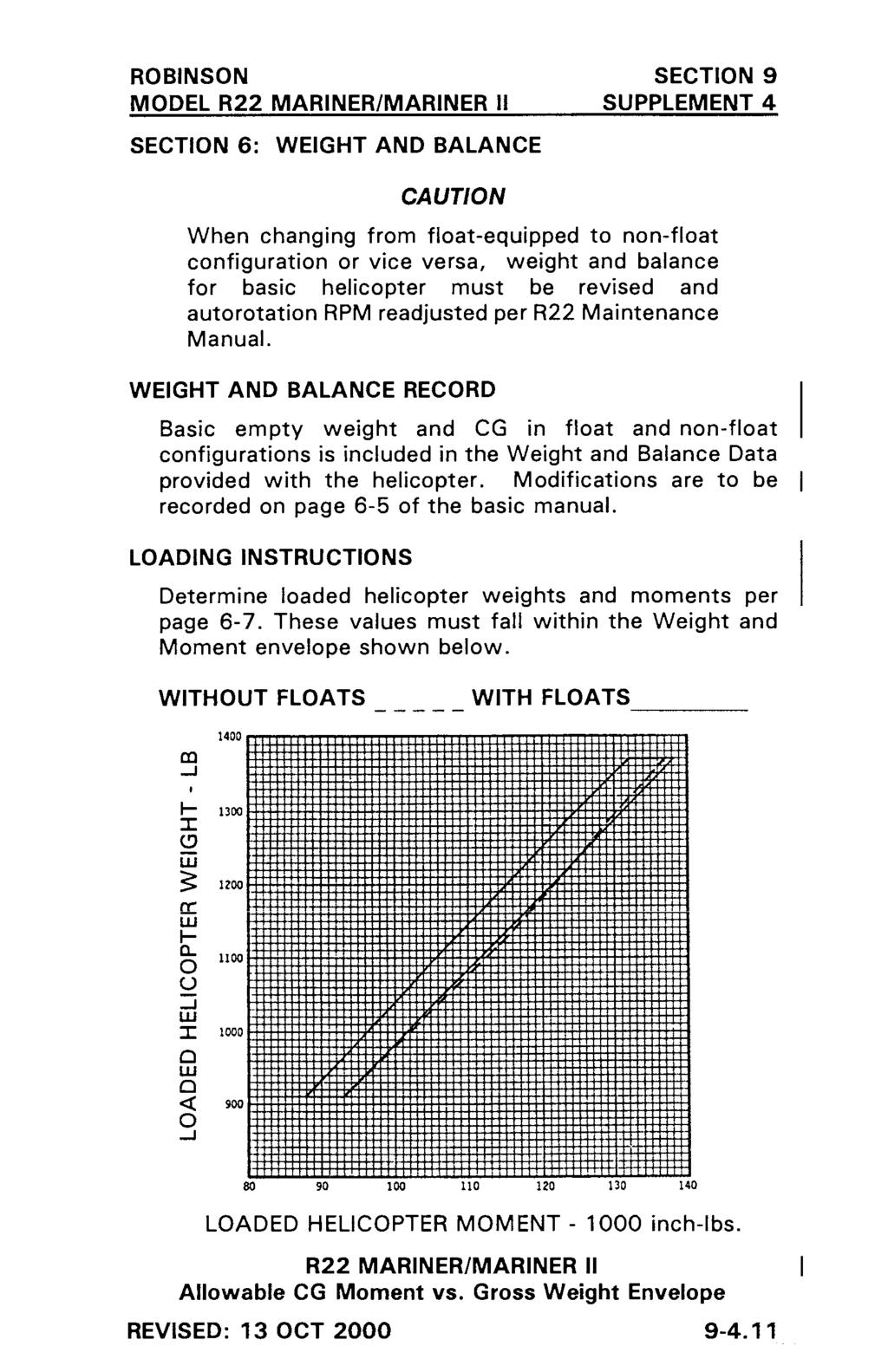
155
156
157
158
159 ROBINSON R22 SERIES SECTION 9 ADS-B EQUIPMENT SUPPLEMENT FAA APPROVED R22 PILOT S OPERATING HANDBOOK ADS-B EQUIPMENT SUPPLEMENT This supplement must be included in the FAA-approved Pilot s Operating Handbook when ADS-B equipment is installed. The information contained herein supplements or supersedes the basic manual only in those areas listed in this supplement. For limitations, procedures, and performance information not contained in this supplement, consult the basic Pilot s Operating Handbook. APPROVED BY: DATE: Manager, Flight Test Branch, ANM-160L Federal Aviation Administration, LAACO Transport Airplane Directorate LOG OF PAGES Page No. Date Page No. Date * 21 Feb Feb * 21 Feb Feb 14 *Manufacturer s data, not FAA approved
160 ROBINSON R22 SERIES SECTION 9 ADS-B EQUIPMENT SUPPLEMENT SECTION 1: GENERAL INTRODUCTION This supplement contains the changes and additional data applicable when Automatic Dependent Surveillance- Broadcast (ADS-B) equipment is installed. ADS-B is divided into two categories ADS-B Out and ADS-B In. ADS-B Out equipment transmits information to air traffic control to supplement radar/transponder information. The supplemental information allows optimization of flight plan routes and aircraft spacing. ADS-B Out equipment may be required for operation in certain airspace. The R22 ADS-B Out installation has been shown to meet the requirements of 14 CFR NOTE The R22 ADS-B Out system operates on frequency 1090 MHz. This frequency is also accepted for ADS-B Out equipment in most countries outside the United States. The ADS-B Out equipment consists of a GPS receiver connected to the transponder. The transponder has ADS-B broadcast capability and broadcasts GPS position as well as additional pre-programmed information such as aircraft identification and size to air traffic control. ADS-B In equipment receives traffic and weather information and displays the information for the pilot to aid situational awareness. ADS-B In equipment is not required for general aviation operations in the United States. Only ADS-B Out is available on the R22. ISSUED: 21 FEB
161 ROBINSON R22 SERIES SECTION 9 ADS-B EQUIPMENT SUPPLEMENT SECTION 2: LIMITATIONS PLACARDS On transponder when ADS-B Out equipment is installed: ADS-B OUT INSTALLED SECTION 3: EMERGENCY PROCEDURES No change. SECTION 4: NORMAL PROCEDURES ADS-B SYSTEM OPERATION ADS-B system operation is mostly automatic and requires little pilot action. The GPS and transponder must be powered and in normal operating modes for proper system function. The R22 ADS-B Out system is a single point of entry system. Mode 3/A codes, IDENT commands, and emergency codes are set on the transponder and are automatically incorporated in ADS-B Out broadcasts. The transponder should transition to ALT mode after takeoff for proper ADS-B Out broadcasts. ADS-B Out broadcasts may be selected off by using menus associated with the transponder FUNC key. NOTE ADS-B Out may be required in certain airspace. Do not turn off ADS-B Out unless directed by air traffic control. Malfunctions in the ADS-B Out system are annunciated by various messages on the GPS screen (refer to GPS manufacturer s documentation) and by a no ADS-B indication on the transponder screen. SECTION 5: PERFORMANCE No change. FAA APPROVED: 21 FEB
162 ROBINSON R22 SERIES SECTION 9 ADS-B EQUIPMENT SUPPLEMENT SECTION 6: WEIGHT AND BALANCE No change. SECTION 7: SYSTEM DESCRIPTION ADS-B SYSTEM The ADS-B Out system consists of a GPS receiver connected to the transponder which broadcasts the aircraft s position, identification, and certain other parameters to air traffic control. ADS-B data is broadcast via the Extended Squitter (ES) feature of the transponder on a frequency of 1090 MHz. Note that change of aircraft registration may require update of pre-programmed parameters by qualified maintenance personnel. Most of the data required for ADS-B broadcast such as aircraft type, ICAO address, and call sign are preprogrammed at installation. Flight-specific data such as Mode 3/A code and IDENT are entered using the transponder controls. The transponder uses these codes simultaneously for standard transponder as well as ADS-B broadcasts. There is no need to make a second code entry or to enter a code more than once. This is known as a single point of entry ADS-B system. SECTION 8: No change. HANDLING, SERVICING AND MAINTENANCE ISSUED: 21 FEB
163
164
165
166
167
168 ROBINSON R22 SERIES SECTION 10 SAFETY TIPS SAFETY NOTICES The following Safety Notices have been issued by Robinson Helicopter Company as a result of various accidents and incidents. Studying the mistakes made by other pilots will help you avoid making the same errors. Safety Notices are available on the RHC website: SAFETY NOTICE TITLE SN-1 Inadvertent Actuation of Mixture Control in Flight SN-9 Many Accidents Involve Dynamic Rollover SN-10 Fatal Accidents Caused by Low RPM Rotor Stall SN-11 Low-G Pushovers - Extremely Dangerous SN-13 Do Not Attach Items to the Skids SN-15 Fuel Exhaustion Can Be Fatal SN-16 Power Lines Are Deadly SN-17 Never Exit Helicopter with Engine Running Hold Controls When Boarding Passengers Never Land in Tall Dry Grass SN-18 Loss of Visibility Can Be Fatal Overconfidence Prevails in Accidents SN-19 Flying Low Over Water is Very Hazardous SN-20 Beware of Demonstration or Initial Training Flights SN-22 Always Reduce Rate-of-Descent Before Reducing Airspeed SN-23 Walking into Tail Rotor Can Be Fatal SN-24 Low RPM Rotor Stall Can Be Fatal SN-25 Carburetor Ice SN-26 Night Flight Plus Bad Weather Can Be Deadly SN-27 Surprise Throttle Chops Can Be Deadly SN-28 Listen for Impending Bearing Failure Clutch Light Warning SN-29 Airplane Pilots High Risk When Flying Helicopters SN-30 Loose Objects Can Be Fatal SN-31 Governor Can Mask Carb Ice SN-32 High Winds or Turbulence SN-33 Drive Belt Slack SN-34 Aerial Survey and Photo Flights - Very High Risk SN-35 Flying Near Broadcast Towers SN-36 Overspeeds During Liftoff SN-37 Exceeding Approved Limitations Can Be Fatal SN-38 Practice Autorotations Cause Many Training Accidents SN-39 Unusual Vibration Can Indicate a Main Rotor Blade Crack SN-40 Post-Crash Fires SN-41 Pilot Distractions SN-42 Unanticipated Yaw SN-43 Use Extra Caution During Post-Maintenance Flights REVISED: 5 MAR
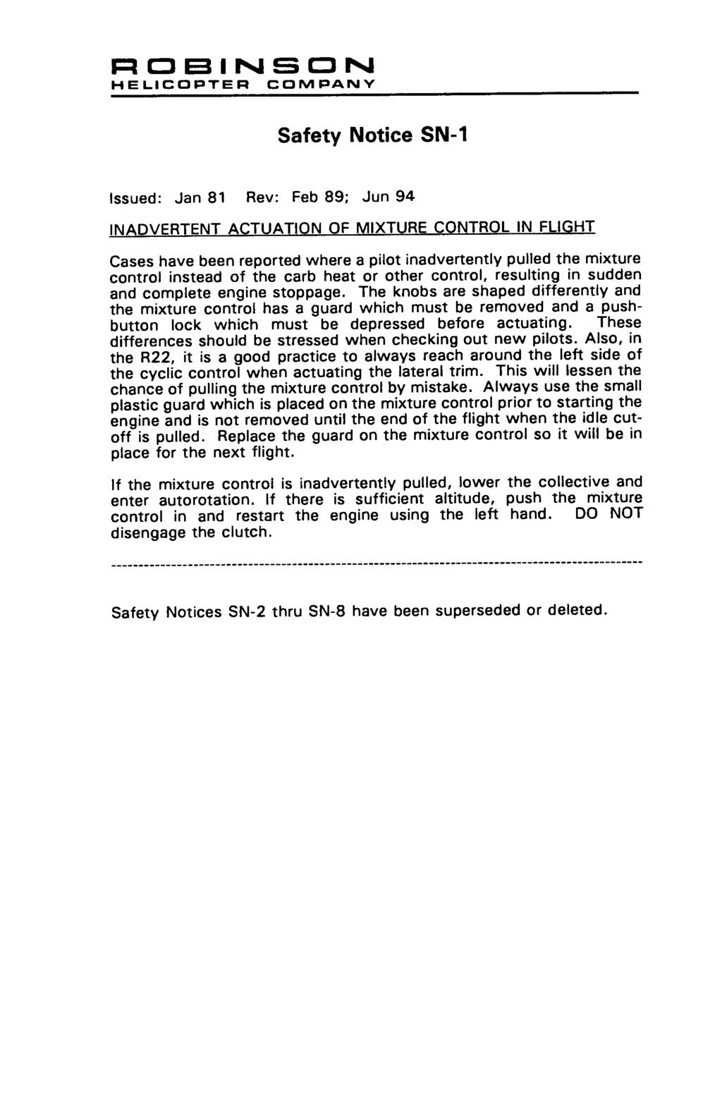
169
170
171
172
173
174
175

176
177
178
179
180
181
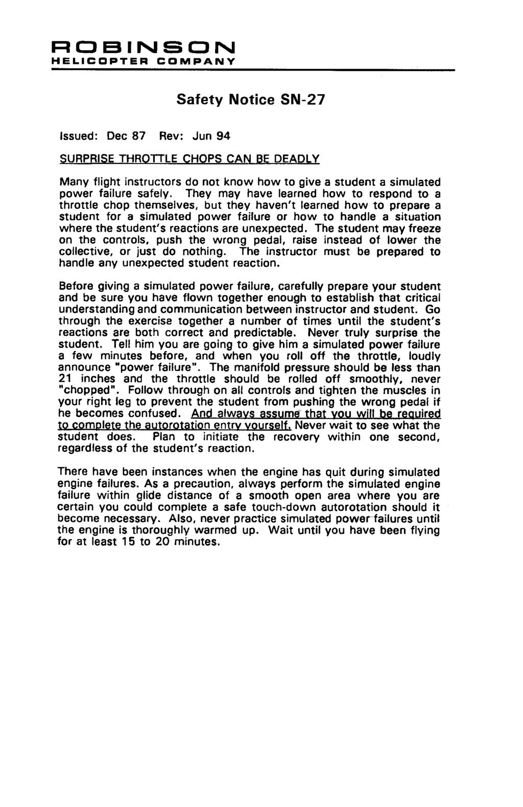
182
183
184
SECTION 4 NORMAL PROCEDURES CONTENTS
 CONTENTS Page Recommended Airspeeds....................... 4-1 Daily or Preflight Checks........................ 4-1 Before Starting Engine.......................... 4-6 Starting Engine and Run-Up......................
SECTION 4 NORMAL PROCEDURES CONTENTS
 CONTENTS Page Recommended Airspeeds....................... 4-1 Daily or Preflight Checks........................ 4-1 Before Starting Engine.......................... 4-6 Starting Engine and Run-Up......................
SECTION 4 NORMAL PROCEDURES CONTENTS
 CONTENTS Page Recommended Airspeeds....................... 4-1 Daily or Preflight Checks........................ 4-1 Before Starting Engine.......................... 4-6 Engine Starting Tips...........................
R22 PILOT'S OPERATING HANDBOOK ROBINSON HELICOPTER CO. AND FAA APPROVED ROTORCRAFT FLIGHT MANUAL RTR 061 TORRANCE, CALIFORNIA
 R22 PILOT'S OPERATING HANDBOOK AND FAA APPROVED ROTORCRAFT FLIGHT MANUAL RTR 061 FAA APPROVED IN NORMAL CATEGORY BASED ON FAR 27 AND FAR 21. THIS HANDBOOK INCLUDES THE MATERIAL REQUIRED TO BE FURNISHED
SECTION 2 LIMITATIONS
 GENERAL This section includes operating limitations, instrument markings, and basic placards required for safe operation of the helicopter, its engine, and other standard systems. This helicopter is approved
R22 PILOT'S OPERATING HANDBOOK ROBINSON HELICOPTER CO. AND FAA APPROVED ROTORCRAFT FLIGHT MANUAL RTR 061 TORRANCE, CALIFORNIA
 R22 PILOT'S OPERATING HANDBOOK AND FAA APPROVED ROTORCRAFT FLIGHT MANUAL RTR 061 FAA APPROVED IN NORMAL CATEGORY BASED ON FAR 27 AND FAR 21. THIS HANDBOOK INCLUDES THE MATERIAL REQUIRED TO BE FURNISHED
SECTION 3 EMERGENCY PROCEDURES CONTENTS
 CONTENTS Page Definitions.................................. 3-1 Power Failure - General......................... 3-1 Power Failure Above 500 feet AGL................ 3-2 Power Failure Between 8 and 500
R44 CADET PILOT S OPERATING HANDBOOK
 PILOT S OPERATING HANDBOOK AND FAA APPROVED ROTORCRAFT FLIGHT MANUAL RTR 463 THE IS FAA APPROVED IN NORMAL CATEGORY BASED ON 14 CFR PARTS 21 and 27. THIS HANDBOOK INCLUDES THE MATERIAL REQUIRED TO BE FURNISHED
SECTION 7 SYSTEMS DESCRIPTION CONTENTS
 CONTENTS Page General..................................... 7-1 Rotor Systems................................ 7-2 Drive System................................. 7-2 Powerplant..................................
SECTION 4 NORMAL PROCEDURES CONTENTS
 CONTENTS Page Recommended Airspeeds....................... 4-1 Daily or Preflight Checks........................ 4-1 Cold Weather Operation........................ 4-5 Before Starting Engine..........................
Briefings & Checks. Robinson RH44 Raven II. Briefings & Checks Robinson RH44 Raven II. Helicopter Data (Meteo / NOTAM / DABS / W&B)
") Briefings & Checks Helicopter Data (Meteo / NOTAM / DABS / W&B) 1. Immatriculation: HB- 2. Empty weight: lbs 3. Main fuel: (USG x 6= lbs) lbs 5. Pilot / Pax / Baggage: lbs 6. actual TOM / HOGE: lbs / HOGE
Briefings & Checks Helicopter Data (Meteo / NOTAM / DABS / W&B) 1. Immatriculation: HB- 2. Empty weight: lbs 3. Main fuel: (USG x 6= lbs) lbs 5. Pilot / Pax / Baggage: lbs 6. actual TOM / HOGE: lbs / HOGE
CLASS J SUBSCRIPTION SERVICE
 INTENTIONALLY BLANK CLASS J SUBSCRIPTION SERVICE If you wish to receive future changes to R66 Pilot s Operating Handbook and copies of future Safety Notices, send a check or money order for $25 USD to:
CHAPTER 3 LIFE-LIMITED COMPONENTS
 Section Title CHAPTER 3 LIFE-LIMITED COMPONENTS 3.000 Life-Limited Components...................................... 3.1 3.001 Introduction............................................. 3.1 3.002 Time-In-Service
Briefings and Checks Robinson R 44 Raven I
 Briefings and Checks Robinson R 44 Raven I Helicopter Data: 1. Call Sign... HB-ZOC 2. S/N... 1388 3. Empty weight... 1440 lbs 4. Fuel... 5. Weight PIC/PAX... 6. Actual TOM... 7. Actual HOGE... 8. MAX TOM...
R44H PILOT'S OPERATING HANDBOOK
 R44H PILOT'S OPERATING HANDBOOK AND FAA APPROVED ROTORCRAFT FLIGHT MANUAL RTR 462 THE R44n IS FAA APPROVED IN NORMAL CATEGORY BASED ON FAR 27 AND FAR 21. THIS HANDBOOK INCLUDES THE MATERIAL REQUIRED TO
CHAPTER 3 LIFE-LIMITED COMPONENTS
 CHAPTER 3 LIFE-LIMITED COMPONENTS Section Title 3.100 Life-Limited Components..................................... 3.1 3.110 Time-in-Service Records................................... 3.1 3.120 Fatigue
CARENADO COPYRIGHTS. Normal & Emergency Checklist
 NORMAL PROCEDURES CHECKLIST PREFLIGHT CHECK Control wheel -- RELEASE BELTS Avionics -- OFF Master Switch -- ON Fuel quantity gauges -- CHECK Master switch -- OFF Ignition -- OFF Exterior -- CHECK FOR DAMAGE
CHAPTER 4 AIRWORTHINESS LIMITATIONS
 Section Title CHAPTER 4 AIRWORTHINESS LIMITATIONS 4-10 Airworthiness Limitations..................................... 4.1 4-20 Additional Limitations....................................... 4.3 4-21 Parts
CHAPTER 6 POWERPLANT
 Section Title CHAPTER 6 POWERPLANT 6.000 Powerplant And Related Systems................................ 6.1 6.001 Introduction............................................ 6.1 6.002 Description.............................................
Van s Aircraft RV-7A. Pilot s Operating Handbook N585RV
 Van s Aircraft RV-7A Pilot s Operating Handbook N585RV PERFORMANCE SPECIFICATIONS SPAN:..25 0 LENGTH...20 4 HEIGHT:.. 7 10 SPEED: Maximum at Sea Level...180 knots Cruise, 75% Power at 8,000 Ft...170 knots
Jump to Table of Contents
 Jump to Table of Contents PIPER AIRCRAFT CORPORATION PA-28R-201, CHEROKEE ARROW III SECTION 3 EMERGENCY PROCEDURES 3.3 EMERGENCY PROCEDURES CHECK LIST ENGINE FIRE DURING
TYPE CERTIFICATE DATA SHEET
 TYPE CERTIFICATE DATA SHEET No. EASA.IM.R.120 for Type Certificate Holder Robinson Helicopter Company 2901 Airport Drive Torrance, CA 90505 U.S.A. For Models:, Alpha, Beta, Mariner TE.CERT.00049-001 European
Robinson R44. Systems
 Robinson R44 Systems The airframe is primarily a metal construction. The primary fuselage is welded steel tubing and riveted aluminium sheet. The tailcone is an aluminium semi-monocoque structure where
a. Lycoming IO-520J 250 HP c. Lycoming O-540-J3C5D 235 HP b. Continental O450T 330 HP d. Lycoming O-360A 180 HP
 Three points each question Page 1 of 6 References: Pilot's Operating Handbook for the 1979 Cessna R182 Model; Flying Magazine Article "Cessna 182 Safety Report;" RAFA SOP; and Refueling Instructions found
CESSNA 182 CHECKLIST. LEFT WING Trailing Edge 1. Aileron CHECK freedom of movement and security
 CESSNA 182 CHECKLIST PRE-FLIGHT INSPECTION CABIN 1. Pilot s Operating Handbook AVAILABLE IN THE AIRPLANE (A.R.R.O.W.E) 2. Landing Gear Lever DOWN 3. Control Wheel Lock REMOVE 4. Ignition Switch OFF 5.
PIPER CUB J3-65 N68952 PRE-FLIGHT CHECKLIST COCKPIT
 PIPER CUB J3-65 N68952 PRE-FLIGHT CHECKLIST COCKPIT Check airworthiness certificate, registration, weight & balance documentation Battery - CONNECTED Plug in headsets or secure as required Fuel ON Magnetos
Robinson R22 Pilot s Technical Quiz
 Robinson R22 Pilot s Technical Quiz Version 1.0a 2002-10-21 Candidate Examiner Name Licence class Licence number Name Licence number Capacity Centre Date Mark (Pass is 80/100= 80%) Instructions: This is
Interior Pre Flight Documents: Check Control Wheel Lock: Remove Flight Controls: Check Instruments: Check for Damage Switches: Verify All Off Master
 Interior Pre Flight Documents: Check Control Wheel Lock: Remove Flight Controls: Check Instruments: Check for Damage Switches: Verify All Off Master Switch ALT/BAT: On Fuel Gauge: Check Quantity Flaps:
Cessna 172P PPL Checklist Page 1
 Cessna 172P PPL Checklist 06-08-2017 Page 1 Cessna 172P PPL Checklist 06-08-2017 Page 2 Checklist Items Informational Items Critical Memory Items PREFLIGHT COCKPIT CHECK (DO-LIST) Pitot Cover -- REMOVE
CHAPTER 18 WEIGHT AND BALANCE
 CHAPTER 18 WEIGHT AND BALANCE Section Title 18-10 Leveling................................................. 18.1 18-11 Leveling at Lower Right Side Frame Tube & Aft Landing Gear Cross Tube.. 18.1 18-12
PIPER CUB J3-65 N68952 PRE-FLIGHT CHECKLIST
 PRE-FLIGHT CHECKLIST COCKPIT Check airworthiness certificate, registration, weight & balance documentation Battery - CONNECTED Plug in headsets or secure as required Fuel ON Primer CLOSED & LOCKED Carb
Vso 61. Vs1 63. Vr 70. Vx 76. Vxse 78. Vy 89. Vyse. 89 (blue line) Vmc. 61 (radial redline) Vsse 76. Va 134) Vno 163
 Vmc. 61 (radial redline) Vsse 76. Va 134) Vno 163") PA34-200T Piper Seneca II Normal procedures V-speeds Knots Vso 6 Vs 63 Vr 70 Vx 76 Vxse 78 Vy 89 Vyse Vmc 89 (blue line) 6 (radial redline) Vsse 76 Va 2-36(@4507lbs 34) Vno 63 Vfe 38 (0*)/2(25*)/07(40*)
PA34-200T Piper Seneca II Normal procedures V-speeds Knots Vso 6 Vs 63 Vr 70 Vx 76 Vxse 78 Vy 89 Vyse Vmc 89 (blue line) 6 (radial redline) Vsse 76 Va 2-36(@4507lbs 34) Vno 63 Vfe 38 (0*)/2(25*)/07(40*)
I. DISPATCH PLANNING & AIRCRAFT EXTERIOR CHECK
 SCHODACK AVIATION Page 1 of 10 I. DISPATCH PLANNING & AIRCRAFT EXTERIOR CHECK 1. Flight Planning 1. Aircraft requirements & preparation: Required aircraft documents: Airworthiness Certificate Registration
INDEX: Normal Procedures Emergency Procedures Pre Flight Inspection NORMAL PROCEDURES BEFORE STARTING ENGINE
 INDEX: Normal Procedures Emergency Procedures Pre Flight Inspection NORMAL PROCEDURES BEFORE STARTING ENGINE 1. Preflight Inspection -- COMPLETE 2. Seats, Belts, Shoulder Harnesses -- ADJUST and LOCK 3.
Van s Aircraft RV-4. Pilot s Operating Handbook
 Van s Aircraft RV-4 Pilot s Operating Handbook PERFORMANCE SPECIFICATIONS SPAN:.. 23 0 LENGTH:. 19 9 HEIGHT:. 6 8 SPEED: Maximum at Sea Level.. Cruise, 75% Power at 8,000 Ft.. 173 Knots 165 Knots RANGE
N1523J CHECKLIST PA Nebraska Flight Center Eppley Airfield 3737 Orville Plaza Omaha, NE Tel. (402)
") CHECKLIST N1523J 1967 Cherokee 140 PA-28-140 F Nebraska Flight Center Eppley Airfield 3737 Orville Plaza Omaha, NE 68110 Tel. (402) 342-4314 www.nebflight.com Piper Cherokee 140 N1523J 1967 GENERAL INFORMATION
CHECKLIST N1523J 1967 Cherokee 140 PA-28-140 F Nebraska Flight Center Eppley Airfield 3737 Orville Plaza Omaha, NE 68110 Tel. (402) 342-4314 www.nebflight.com Piper Cherokee 140 N1523J 1967 GENERAL INFORMATION
Preflight Inspection Cabin EMPENNAGE RIGHT WING Trailing Edge RIGHT WING NOSE
 Preflight Inspection Cabin 1. Control Wheel Lock REMOVED 2. Ignition Switch OFF 3. Avionics Power Switch OFF 4. Master Switch ON 5. Fuel Quantity Indicators CHECK QUANTITY 6. Master Switch OFF 7. Fuel
I. DISPATCH PLANNING & AIRCRAFT EXTERIOR CHECK
 SCHODACK AVIATION Page 1 of 10 I. DISPATCH PLANNING & AIRCRAFT EXTERIOR CHECK 1. Flight Planning 1. Aircraft requirements & preparation: 1. Required aircraft documents: 1. Airworthiness Certificate 2.
Document No. ST-931-RFM-0001
 275 Palos Verdes Dr. North Document No. ST-931-RFM-1 FAA APPROVED Rotorcraft Flight Manual Supplement to the Robinson R44 Pilot s Operating Handbook and FAA Approved Rotorcraft Flight Manual HeliSAS Aircraft
ADVANCED TECHNOLOGY. Automatic Clutch Engagement. Simplifies startup procedure and reduces the possibility of an overspeed.
 ADVANCED TECHNOLOGY Advanced Warning Devices. The instrument panel includes low fuel warning light, main gearbox temperature and chip lights, tail gearbox chip light, low oil pressure light, engine fire
Accident Prevention Program
 Accident Prevention Program Maintenance Aspects of Owning Your Own Airplane Introduction As an owner-pilot, FAR Part 43 allows you to perform certain types of inspections and maintenance on your airplane.
R44 RAVEN CLIPPER SPECIFICATIONS DIMENSIONS ROBINSON HELICOPTER COMPANY
 SPECIFICATIONS Engine Horsepower RAVEN I Lycoming O-540, six cylinder, carbureted Derated to 225 for takeoff and 205 continuous RAVEN II Lycoming IO-540, six cylinder, fuel injected Derated to 245 for
DO NOT WRITE ON THIS TEST FEB 2013 Elmendorf Aero Club Aircraft Test. Cessna - 182
 DO NOT WRITE ON THIS TEST FEB 2013 Elmendorf Aero Club Aircraft Test Cessna - 182 For the following questions, you will need to refer to the Pilots Information Manual for the C-182R. The bonus questions
Elmendorf Aero Club Aircraft Test
 DO NOT WRITE ON THIS TEST FEB 2013 Elmendorf Aero Club Aircraft Test Cessna - 182 For the following questions, you will need to refer to the Pilots Information Manual for the C-182R. The bonus questions
PA32-RT LANCE II CHECKLIST
 PA32-RT LANCE II CHECKLIST 6815.10.1112 1 Normal Procedures PREFLIGHT CHECK Control Wheel... RELEASE BELTS Parking brake... Set Master Switch... ON Fuel Quantity Gauges... check Master Switch... OFF Ignition...
Piper Archer II (PA )
") 1. Oil... 6-8 qts, Cap Secure CABIN 1. POH & Documents.. Check Available 2. Magneto Switch...... OFF 3. Pitot/Static Drains... Push to Drain 4. Avionics/Electrical Switches... OFF 5. Master Switch. ON
1. Oil... 6-8 qts, Cap Secure CABIN 1. POH & Documents.. Check Available 2. Magneto Switch...... OFF 3. Pitot/Static Drains... Push to Drain 4. Avionics/Electrical Switches... OFF 5. Master Switch. ON
UNCONTROLLED COPY WHEN DOWNLOADED OR PRINTED ENSTROM 280FX OPERATOR S MANUAL. Record of Revisions. Date Inserted
 ENSTROM 280FX OPERATOR S MANUAL Record of Revisions Revision Number Issue Date Date Inserted By 1 12/31/80 2/21/12 J. Wingers 2 1/11/85 2/21/12 J. Wingers 3 7/12/85 2/21/12 J. Wingers 4 1/11/91 2/21/12
CHAPTER 13 INSTRUMENTS
 CHAPTER 13 INSTRUMENTS Section Title Page 13.000 Description.............................................. 13.1 13.100 Pitot-Static System......................................... 13.3 13.200 Primary Instruments........................................
TYPE CERTIFICATE DATA SHEET
 TYPE CERTIFICATE DATA SHEET No. EASA.IM.R.121 for Type Certificate Holder Robinson Helicopter Company 2901 Airport Drive Torrance, CA 90505 U.S.A. For Models:, II TE.CERT.00049-001 European Aviation Safety
NORMAL CHECKLIST ATTENTION!
 Avion Training CHECKLIST Normal Checklist CESSNA 172R / TC-STS Cessna 172 R TC-STS NORMAL CHECKLIST ATTENTION! DO NOT STOW THIS CHECKLIST IN DIRECT SUNLIGHT Avion Training - Doc.nr. 212 Revision 1 / 02022018
LANCAIR LEGACY PRE-TEST FLIGHT INSPECTION (8-04)
") LANCAIR LEGACY PRE-TEST FLIGHT INSPECTION (8-04) OWNER PHONE # ADDRESS N SERIAL # AIRCRAFT TYPE DATE / / TACH TIME hrs. TOTAL TIME hrs. EMPTY WEIGHT CG. PAINT & INTERIOR? YES NO ENGINE TYPE PROPELLER ALL
LANCAIR LEGACY PRE-TEST FLIGHT INSPECTION (8-04) OWNER PHONE # ADDRESS N SERIAL # AIRCRAFT TYPE DATE / / TACH TIME hrs. TOTAL TIME hrs. EMPTY WEIGHT CG. PAINT & INTERIOR? YES NO ENGINE TYPE PROPELLER ALL
CHAPTER 11 FLIGHT CONTROLS
 CHAPTER 11 FLIGHT CONTROLS CONTENTS INTRODUCTION -------------------------------------------------------------------------------------------- 3 GENERAL ---------------------------------------------------------------------------------------------------------------------------
CHECKLIST 1969 CESSNA 172-K. NOTE: Verify all information with airplane's POH
 CHECKLIST 1969 CESSNA 172-K NOTE: Verify all information with airplane's POH PRE-FLIGHT INSPECTION 1 CABIN 1 A.R.R.O.W. CHECK Airworthiness Cert. In Clear View Registration In Clear View Radio License
N123AX Piper Saratoga II HP (PA-32R-301) Checklist (v23 - Revision 3 April 2011) AIRSPEEDS FOR SAFE OPERATIONS. Best Rate of Climb (gear up, flaps up)
 Checklist (v23 - Revision 3 April 2011) AIRSPEEDS FOR SAFE OPERATIONS. Best Rate of Climb (gear up, flaps up)") N123AX Piper Saratoga II HP (PA-32R-301) Checklist (v23 - Revision 3 April 2011) AIRSPEEDS FOR SAFE OPERATIS Best Rate of Climb (gear down, flaps up) Best Rate of Climb (gear up, flaps up) Turbulent Air
N123AX Piper Saratoga II HP (PA-32R-301) Checklist (v23 - Revision 3 April 2011) AIRSPEEDS FOR SAFE OPERATIS Best Rate of Climb (gear down, flaps up) Best Rate of Climb (gear up, flaps up) Turbulent Air
SECTION IV NORMAL PROCEDURES TABLE OF CONTENTS
 SECTION IV NORMAL PROCEDURES TABLE OF CONTENTS SUBJECT PAGE Speeds for Safe Operation 4-3 Preflight Inspection 4-4 Before Starting 4-5 External Power 4-6 Starting Engine Using Auxiliary Power Unit. 4-7
JODEL D.112 INFORMATION MANUAL C-FVOF
 JODEL D.112 INFORMATION MANUAL C-FVOF Table of Contents I General Description...4 Dimensions:...4 Powertrain:...4 Landing gear:...4 Control travel:...4 II Limitations...5 Speed limits:...5 Airpeed indicator
OUTLINE. Commercial Requirements Insurance Mins Basic Info Systems Limitations Performance Charts Questions
 T-34B GROUND SCHOOL OUTLINE Commercial Requirements Insurance Mins Basic Info Systems Limitations Performance Charts Questions COMMERCIAL REQUIREMENTS 61.129 Aeronautical experience. (a) For an airplane
RAVEN. ROBINSON s R44 RAVEN SERIES provides excellent reliability, responsive RAVEN II RAVEN I PATENTED T-BAR CYCLIC PISTOL-GRIP CYCLIC
 RAVEN & CLIPPER RAVEN ROBINSON s R44 RAVEN SERIES provides excellent reliability, responsive handling, and altitude performance, making the R44 the ideal helicopter for private, business, and utility applications.
INDEX. Preflight Inspection Pages 2-4. Start Up.. Page 5. Take Off. Page 6. Approach to Landing. Pages 7-8. Emergency Procedures..
 INDEX Preflight Inspection Pages 2-4 Start Up.. Page 5 Take Off. Page 6 Approach to Landing. Pages 7-8 Emergency Procedures.. Page 9 Engine Failure Pages 10-13 Propeller Governor Failure Page 14 Fire.
Cessna 172 Skyhawk. Aircraft Checklist Models: R & S
 Cessna 172 Skyhawk Aircraft Checklist Models: R & S This is an abbreviated checklist. Most explanatory items, notes cautions and warnings have been omitted for brevity. Procedures in red/bold text in this
DEPARTMENT OF TRANSPORTATION FEDERAL AVIATION ADMINISTRATION TYPE CERTIFICATE DATA SHEET NO. A13CE
 DEPARTMENT OF TRANSPORTATION FEDERAL AVIATION ADMINISTRATION A13CE Revision 28 CESSNA 177 177A 177B November 16, 2010 TYPE CERTIFICATE DATA SHEET NO. A13CE WARNING: Use of alcohol-based fuels can cause
Flight Checklist for Normal Operations Massgebend ist das AFM (Parameters, Restrictions, Emergency, etc.)
") Flight Checklist for Normal Operations Massgebend ist das AFM (Parameters, Restrictions, Emergency, etc.) Jan18 1 COCKPIT PREPARATION BEFORE STARTING ENGINE 1 Aircraft + Cockpit Inspection COMPLETED 1
Flight Checklist for Normal Operations Massgebend ist das AFM (Parameters, Restrictions, Emergency, etc.) Jan18 1 COCKPIT PREPARATION BEFORE STARTING ENGINE 1 Aircraft + Cockpit Inspection COMPLETED 1
PA , Model E Normal Checklist (04/15/11)
") PA-23-250, Model E Normal Checklist (04/15/11) Key Airspeeds IAS-MPH V NE 249 V NO 198 V LO/LE 150 V A (At max gross weight.) 149 Speed for single engine cruise. 138 V FE Quarter Flaps 160 Half Flaps 140
PA-23-250, Model E Normal Checklist (04/15/11) Key Airspeeds IAS-MPH V NE 249 V NO 198 V LO/LE 150 V A (At max gross weight.) 149 Speed for single engine cruise. 138 V FE Quarter Flaps 160 Half Flaps 140
SECTION 9 SUPPLEMENTS
 ROBINSON MODEL R44 II SECTION 9 SUPPLEMENTS SECTION 9 SUPPLEMENTS OPTIONAL EQUIPMENT SUPPLEMENTS Information contained in the following supplements applies only when the related equipment is installed.
Elmendorf Aero Club Aircraft Test
 DO NOT WRITE ON THIS TEST FEB 2013 Elmendorf Aero Club Aircraft Test Cessna 172RG For the following questions, you will need to refer to the Pilots Information Manual for the C-172RG and the Auxiliary
CHAPTER 21 ENVIRONMENT CONTROL. Section Title Page
 CHAPTER 21 ENVIRONMENT CONTROL Section Title Page 21-00 Description........................................ 21.1 21-10 Ventilation........................................ 21.3 21-11 Nose Vent................................
PA GURW (December 30, 2000) PRE-START. Langley Flying School. Airspeeds (MPH) for Safe Operation. Cockpit Checks
 PRE-START. Langley Flying School. Airspeeds (MPH) for Safe Operation. Cockpit Checks") Langley Flying School PA-34-200 GURW (December 30, 2000) Airspeeds (MPH) for Safe Operation V y (all weights) 105 V x (all weights) 90 En Route Climb 120 V mc 80 V yse 105 V xse 93 V r 80 V r (25 Flaps)
Langley Flying School PA-34-200 GURW (December 30, 2000) Airspeeds (MPH) for Safe Operation V y (all weights) 105 V x (all weights) 90 En Route Climb 120 V mc 80 V yse 105 V xse 93 V r 80 V r (25 Flaps)
APICAL S-76 BAGGAGE DOOR LIFERAFT KIT
 2608 Temple Heights Dr. FAA APPROVED ROTORCRAFT FLIGHT MANUAL SUPPLEMENT TO THE SIKORSKY MODELS S-76A, S-76B, & S-76C FAA APPROVED ROTORCRAFT FLIGHT MANUAL When Equipped with APICAL S-76 BAGGAGE DOOR LIFERAFT
AIR TRACTOR, INC. OLNEY, TEXAS
 TABLE OF CONTENTS LOG OF REVISIONS... 2 DESCRIPTION... 4 SECTION 1 LIMITATIONS... 5 SECTION 2 NORMAL PROCEDURES... 8 SECTION 3 EMERGENCY PROCEDURES... 8 SECTION 4 MANUFACTURER'S SECTION - PERFORMANCE...
CHAPTER 17 LIMITATIONS TABLE OF CONTENTS
 CHAPTER 17 LIMITATIONS TABLE OF CONTENTS INTRODUCTION... 5 GENERAL... 5 Flight Crew... 6 Configuration... 6 Optional Equipment... 6 Doors Opened / Removed... 6 Passenger Seats... 6 Cargo... 7 Weight and
DEPARTMENT OF TRANSPORTATION FEDERAL AVIATION ADMINISTRATION TYPE CERTIFICATE DATA SHEET NO. A16EA
 DEPARTMENT OF TRANSPORTATION FEDERAL AVIATION ADMINISTRATION A16EA Revision 15 True Flight Holdings LLC AA-5, AA-5A, AA-5B AG-5B September 18, 2009 TYPE CERTIFICATE DATA SHEET NO. A16EA This data sheet,
RAVEN & CLIPPER ROBINSON HELICOPTER COMPANY
 RAVEN & CLIPPER ROBINSON HELICOPTER COMPANY RAVEN The ROBINSON R44 RAVEN SERIES provides excellent reliability, responsive handling, and altitude performance, making the R44 ideal for private, business,
Liberty Aerospace, Inc. Section 1 SECTION 1 GENERAL TABLE OF CONTENTS
 Liberty Aerospace, Inc. Section 1 SECTION 1 TABLE OF CONTENTS Introduction... 1-3 Airplane Three Views... 1-4 Descriptive Data... 1-5 Engine... 1-5 Propeller... 1-5 Fuel... 1-5 Oil... 1-5 Maximum Certificated
Cessna 182S-CHECKLIST PROCEDURES
 Cessna 182S-CHECKLIST PROCEDURES PREFLIGHT INSPECTION 1 CABIN 1. Pitot Tube Cover -- REMOVE (if installed) and check for stoppage 2. Pilot s Operating Handbook AVAILABLE IN THE AIRPLANE 3. Airplane Weight
USAF Aero Club T-41B (Cessna R-172E) Aircraft Exam Updated February 2017
 Aircraft Exam Updated February 2017") USAF Aero Club T-41B (Cessna R-172E) Aircraft Exam Updated February 2017 Instructions Complete the supplement following exam using the answer sheet provided. Do not assume information not specifically
USAF Aero Club T-41B (Cessna R-172E) Aircraft Exam Updated February 2017 Instructions Complete the supplement following exam using the answer sheet provided. Do not assume information not specifically
Checklist Robin DR40
 Flight Checklist for Normal Operations Massgebend ist das AFM (Parameters, Restrictions, Emergency, etc.) Jan 18 1 COCKPIT PREPARATION BEFORE STARTING ENGINE 1 Aircraft + Cockpit Inspection COMPLETED 1
PA28R ARROW CHECKLIST
 PA28R ARROW CHECKLIST 2300.11.0112 1 Normal Procedures Initial PREFLIGHT CHECK General Appearance... CHECKED Position & Taxi Path... CHECKED Tie Downs, Locks, Chocks & Covers... REMOVED Cockpit Controls...UNLOCKED
Wings of Carolina Flying Club PA Aircraft Type Checkout and Currency Quiz
 Wings of Carolina Flying Club PA-28-161 Aircraft Type Checkout and Currency Quiz Pilot Instructor Score Date Instructor: Please note the final score (subtract 2.5 points from 100 for each wrong answer)
V - Speeds. RV-10 V fe Flaps Speeds Trail (0 deg) Half (15 deg) Full (30 deg) 122 kias 96 kias. 80 kias
 Half (15 deg) Full (30 deg) 122 kias 96 kias. 80 kias") RV-10 Check List V - Speeds RV-10 V fe Flaps Speeds Trail (0 deg) Half (15 deg) Full (30 deg) 122 kias 96 kias 87 kias V s1 Stall (Flap Up) 60 kias V s0 Stall (Flap 40 deg) 55 kias Best Glide 80 kias V
RV-10 Check List V - Speeds RV-10 V fe Flaps Speeds Trail (0 deg) Half (15 deg) Full (30 deg) 122 kias 96 kias 87 kias V s1 Stall (Flap Up) 60 kias V s0 Stall (Flap 40 deg) 55 kias Best Glide 80 kias V
Flight checklist for normal operations Massgebend ist das AFM (parameters, restrictions, emergency, etc.)
") JAN13 1 Flight checklist for normal operations Massgebend ist das AFM (parameters, restrictions, emergency, etc.) Cockpit preparation before starting engine 1 Aircraft + Cockpit inspection completed (according
JAN13 1 Flight checklist for normal operations Massgebend ist das AFM (parameters, restrictions, emergency, etc.) Cockpit preparation before starting engine 1 Aircraft + Cockpit inspection completed (according
Elmendorf Aero Club Aircraft Test
 DO NOT WRITE ON THIS TEST FEB 2014 Elmendorf Aero Club Aircraft Test Cessna - 185 For the following questions, you will need to refer to the Pilots Information Manual for the C-185F and Graphic Engine
FAA APPROVED. Dated: January 20, Airplane Serial No:
 INSTALLATION OF SADDLE TANKS FOR BEECHCRAFT KING AIR AIRPLANES 200, 200C, A200, A200C, B200, B200C, B200GT, B200CGT 300, B300, AND B300C SUPPLEMENTAL TYPE CERTIFICATE NUMBER SA11142SC FAA APPROVED Airplane
CHAPTER 13 INSTRUMENT SYSTEM
 CHAPTER 13 INSTRUMENT SYSTEM Section Title 13-00 Description............................................... 13.1 13-10 Pitot-Static System......................................... 13.3 13-20 Primary Instruments.........................................
Elmendorf Aero Club Aircraft Test
 DO NOT WRITE ON THIS TEST JAN 2014 Elmendorf Aero Club Aircraft Test SENECA II For the following questions, you will need to refer to the Pilots Information Manual for the PA-34-200T. USE ANSWER SHEET
AIRPLANE FLIGHT MANUAL
 Thrush Aircraft Inc Model S2R-R1340 MANUAL ORGANIZATION SECTION I -----------------------------------------------------LIMITATIONS SECTION II -------------------------------------- NORMAL PROCEDURES SECTION
Elmendorf Aero Club Aircraft Test
 DO NOT WRITE ON THIS TEST FEB 2013 Elmendorf Aero Club Aircraft Test Cessna - 172 For the following questions, you will need to refer to the Pilots Information Manual for the C-172R (180hp). The bonus
Seabee Annual Inspection Procedures
 Procedures Due to the wide variety of Seabee s flying out there, these procedures should be modified to fit YOUR Seabee. Make sure that all AD s are complied with as well as any required Service Bulletins
CESSNA 172S NAV III VFR CHECKOUT POH EXAMINATION (Based on N1129K, serial no. 172S revised 10/05/06)
") INTRODUCTION, POH CESSNA 172S NAV III VFR CHECKOUT POH EXAMINATION (Based on N1129K, serial no. 172S10315 - revised 10/05/06) 1. Rate of climb at sea level: 2. Service ceiling: 3. Takeoff performance,
INTRODUCTION, POH CESSNA 172S NAV III VFR CHECKOUT POH EXAMINATION (Based on N1129K, serial no. 172S10315 - revised 10/05/06) 1. Rate of climb at sea level: 2. Service ceiling: 3. Takeoff performance,
Gyroplane questions from Rotorcraft Commercial Bank (From Rotorcraft questions that obviously are either gyroplane or not helicopter)
") Page-1 Gyroplane questions from Rotorcraft Commercial Bank (From Rotorcraft questions that obviously are either gyroplane or not helicopter) "X" in front of the answer indicates the likely correct answer.
Page-1 Gyroplane questions from Rotorcraft Commercial Bank (From Rotorcraft questions that obviously are either gyroplane or not helicopter) "X" in front of the answer indicates the likely correct answer.
Registration Number. Serial Number
 Registration Number Serial Number This supplement must be attached to the DMCR Approved Airplane Flight Manual dated October 1, 1954 or later approved revision and must be carried in the airplane when
3. What is the total fuel capacity with normal tanks? Usable? 4. What is the total fuel capacity with long range tanks? Usable?
 Pilot Name: Last, first, mi. Date: (mo/dy/yr) Instructor: Pass/Fail: Instructors Initials: 1. What is the engine Manufacturer: Model: Type: 2. What is the horsepower rating? 3. What is the total fuel capacity
Cessna 172RG WARNING. Maximum Demonstrated Crosswind. Takeoff or landing..15 KTS
 Cessna 172RG INTRODUCTION: This aircraft checklist contains information from the original manufacturer s Pilot Information Manual. Normal procedures associated with optional systems can be found in Section
CHAPTER 8 WEIGHT AND BALANCE. Section Title Page
 CHAPTER 8 WEIGHT AND BALANCE Section Title Page 8-10 Leveling.......................................... 8.1 8-11 Leveling for Weight and Balance................. 8.1 8-12 Leveling for Rigging..........................
CHAPTER 22 SERVICING
 CHAPTER 22 SERVICING Section Title 22-10 Main Rotor Gearbox......................................... 22.1 22-11 Cleaning Chip Detector..................................... 22.3 22-12 Cleaning Sight Gage.......................................
Registration Number. Serial Number
 Registration Number Serial Number This supplement must be attached to the DMCR Approved Airplane Flight Manual listed on page 2 of this supplement or later approved revision and must be carried in the
TECNAM P92 EAGLET N615TA TECNAM P92 EAGLET CHECKLIST [FLIGHT PLAN DESIGNATION IS ECHO ]
![TECNAM P92 EAGLET N615TA TECNAM P92 EAGLET CHECKLIST [FLIGHT PLAN DESIGNATION IS ECHO ]](/thumbs/86/93080937.jpg "TECNAM P92 EAGLET N615TA TECNAM P92 EAGLET CHECKLIST [FLIGHT PLAN DESIGNATION IS ECHO ]") TECNAM P92 EAGLET CHECKLIST [FLIGHT PLAN DESIGNATION IS ECHO ] EMERGENCY CONTACT The following are First Landings' emergency contact telephone numbers. We ask that you call the numbers in the order listed.
TECNAM P92 EAGLET CHECKLIST [FLIGHT PLAN DESIGNATION IS ECHO ] EMERGENCY CONTACT The following are First Landings' emergency contact telephone numbers. We ask that you call the numbers in the order listed.
TYPE CERTIFICATE DATA SHEET
 TYPE CERTIFICATE DATA SHEET No. EASA.R.145 for Type Certificate Holder Hélicoptères Guimbal 1070, rue du Lieutenant Parayre Aérodrome d'aix-en-provence 13290 Les Milles France For Model: TE.CERT.00049-001
QUICK REFERENCE HANDBOOK TECNAM P92 ECHO
 NORMAL LISTS PRE-START S Park brake Left fuel cock Flight Instruments (No broken glass or bent needles) Engine Instruments (No broken glass or bent needles) Right fuel cock Fuses Landing Light Avionics
TECNAM P2004 BRAVO N128LS
 TECNAM P2004 BRAVO N128LS GENERAL INFORMATION NORMAL PROCEDURES TIME SENSITIVE EMERGENCY TECNAM P2004 BRAVO CHECKLIST [FLIGHT PLAN DESIGNATION IS BRAV ] EMERGENCY CONTACT The following are First Landings'
PREFLIGHT CHECK COCKPIT RIGHT WING. NORMAL PROCEDURRES CHECKLIST PA-28RT 201 Arrow IV
 NORMAL PROCEDURRES CHECKLIST PA-28RT 201 Arrow IV PREFLIGHT CHECK COCKPIT Control Wheel -- Release Restraints Avionics -- OFF Parking Brake -- SET All Switches -- OFF Mixture -- IDLE CUT-OFF Master Switch