CLASS J SUBSCRIPTION SERVICE
|
|
|
- Silas Richards
- 6 years ago
- Views:
Transcription
1
2 INTENTIONALLY BLANK
3 CLASS J SUBSCRIPTION SERVICE If you wish to receive future changes to R66 Pilot s Operating Handbook and copies of future Safety Notices, send a check or money order for $25 USD to: ROBINSON HELICOPTER COMPANY 2901 Airport Drive Torrance, CA You will receive all future changes to the Handbook and future Safety Notices for a period of two years. Note: The date stamped below reflects the revision of this handbook at the time it was assembled. Please refer to for date of most recent revision. If outdated, the most recent revision is available for an additional charge of $15 USD. Please print your name, address and telephone number below and return this page together with your U.S. check or money order. Name: Complete Address: Phone: Aircraft Serial Number:
4 INTENTIONALLY BLANK
5 LOG OF PAGES APPROVED BY FAA TYPE CERTIFICATE NO. R00015LA LOG OF PAGES Page No. Approval Date Page No. Approval Date Cover Log of Pages i ii 25 Oct Aug 17 Section 2 Limitations 2-i Oct Oct Nov Nov Oct Aug 17 2 Dec Apr Oct Oct Oct Oct Oct 16 Section 3 Emergency Procedures 3-i Apr Oct Feb Apr Oct Feb Feb Apr Feb Feb Oct 10 Section 4 Normal Procedures 4-i Oct Oct Aug Aug Nov Nov Nov Oct Apr Nov Oct Nov Nov Oct Oct Oct Nov 13 Section 5 Performance 5-i Oct Oct Oct Oct Oct Oct Oct Oct Oct Oct Oct Nov 13 1 Sep 11 Section 9 Supplements 9-i 17 Jan 17 Approved By: Date of Approval: Manager, West Flight Test Section, AIR-716 Federal Aviation Administration Los Angeles, CA ii
6 LOG OF PAGES LOG OF PAGES NOT REQUIRING FAA APPROVAL Page No. Revision Date Page No. Revision Date Section 1 General 1-i Oct Oct Oct Oct Oct Oct Oct Oct Oct Oct Oct 10 Section 6 Weight and Balance 6-i Oct Oct Oct Oct Oct Oct 10 1 Sep 11 1 Sep Oct 10 Section 7 Systems Description 7-i Aug Jan Jan Oct Aug Aug Feb Oct Jan Oct Oct Aug Aug Jan Jan Nov Oct Nov Nov Jan Jan Jan Oct Aug Jan Jan Jan Jan Jan Jan Jan 15 Section 8 Handling and Maintenance 8-i Aug Jan Apr Jan Oct Oct Jan Jan Oct Oct Aug Aug Aug Oct Jan 15 Section 10 Safety Tips 10-i Oct Oct Oct Oct Oct Oct Aug 17 REVISED: 29 AUG 2017 iii
7
8 INTENTIONALLY BLANK
9
10
11
12
13
14
15
16
17
18
19 SECTION 2 LIMITATIONS SECTION 2 LIMITATIONS CONTENTS Page General Color Code for Instrument Markings Airspeed Limits Rotor Speed Limits Powerplant Limitations Weight Limits Center of Gravity Limits Flight and Maneuver Limitations Kinds of Operation Limitations Environmental Limitations Fuel Limitations Instrument Markings Placards FAA APPROVED: 19 OCT i
20 INTENTIONALLY BLANK
21 SECTION 2 LIMITATIONS GENERAL SECTION 2 LIMITATIONS This section includes operating limitations, instrument markings, and basic placards required for safe operation of the helicopter, its engine, and other standard systems. This helicopter is approved as a normal category rotorcraft under FAA Type Certificate No. R00015LA as Model R66. COLOR CODE FOR INSTRUMENT MARKINGS Red Operating limit. Edge of red line indicates limit. Pointer should not enter red during normal operation. Red Cross- Hatch Yellow Green Power-off V ne. Precautionary or special operating procedure range. Normal operating range. AIRSPEED LIMITS NEVER-EXCEED AIRSPEED (V ne ) 2200 lb (998 kg) TOGW or above 130 KIAS Below 2200 lb (998 kg) TOGW 140 KIAS Autorotation 100 KIAS For V ne reductions with altitude and temperature, see placards on page ADDITIONAL AIRSPEED LIMITS 65 KIAS maximum above 83% torque. 100 KIAS maximum with any combination of cabin doors removed. FAA APPROVED: 19 OCT
22 SECTION 2 LIMITATIONS ROTOR SPEED LIMITS TACHOMETER READING ACTUAL RPM Power On Maximum continuous 101% 412 Minimum continuous 99% 404 Power Off Maximum 106% 432 Minimum 88% 359 POWERPLANT LIMITATIONS ENGINE One Rolls-Royce Model 250-C300/A1 OPERATING LIMITS Gas generator speed (N 1 ) Maximum 105 % (53,519 RPM) Output shaft speed (N 2 ) Maximum continuous 101 % (6076 RPM) Minimum continuous power on 99 % (5956 RPM) Maximum transient overspeed* 106 % (6377 RPM) Measured Gas Temperature Maximum during start Maximum operating C (10 second limit above 782 C) C (5 minutes) 706 C (continuous) Torque 5 minute limit 100 % (236 lb-ft) Continuous limit 83 % (196 lb-ft) * Avoid large, rapid power changes. The engine governor reacts slowly and RPM excursions may occur. Intentional operation outside continuous RPM limits is prohibited. Should an inadvertent excursion occur, the transient limit applies. FAA APPROVED: 26 NOV
23 SECTION 2 LIMITATIONS POWERPLANT LIMITATIONS (cont d) OPERATING LIMITS (cont d) Oil Temperature, Maximum 107 C Oil Pressure Maximum during start and warm up 150 psi Maximum operating 130 psi Minimum above 94% N psi Minimum below 78% N 1 50 psi Minimum from 78% to 94% N 1 90 psi Oil Quantity, minimum for takeoff 4 qt (3.8 liters) WEIGHT LIMITS Maximum gross weight Minimum gross weight Maximum per seat including under-seat compartment Maximum in any under-seat compartment 2700 lb (1225 kg) 1400 lb (635 kg) 300 lb (136 kg) 50 lb (23 kg) Baggage Compartment Maximum distributed load 50 lb/ft 2 (244 kg/m 2 ) Maximum total load 300 lb (136 kg) CENTER OF GRAVITY LIMITS See figure on page 2-4. Reference datum is 100 inches forward of main rotor shaft centerline. NOTE With all doors installed and no load in baggage compartment, a solo pilot weight of 160 lb (73 kg) or greater will ensure CG within limits. For lower pilot weight, compute weight and balance; removable ballast may be required to obtain CG at or forward of aft limit. (See Loading Instructions in Section 6.) FAA APPROVED: 26 NOV
24
25 SECTION 2 LIMITATIONS FLIGHT AND MANEUVER LIMITATIONS Aerobatic flight probibited. CAUTION Abrupt control inputs may produce high fatigue stresses and cause catastrophic failure of a critical component. Low-G cyclic pushovers prohibited. CAUTION A pushover (forward cyclic maneuver) performed from level flight or following a pullup causes a low-g (near weightless) condition which can result in catastrophic loss of lateral control. To eliminate a low-g condition, immediately apply gentle aft cyclic. Should a right roll commence during a low-g condition, apply gentle aft cyclic to reload rotor before applying lateral cyclic to stop roll. Maximum operating density altitude 14,000 feet. Maximum operating altitude 9000 feet AGL to allow landing within 5 minutes in case of fire. Closing throttle (twist grip) in flight prohibited above 10,000 feet density altitude to avoid possible engine flameout. Minimum crew is one pilot in the right front seat. A flight instructor may act as pilot in command from the left front seat. Solo flight from right seat only. Forward left seat belt must be buckled. Operation up to 100 KIAS approved with any combination of cabin doors removed. All seat belts must be buckled and loose items in cabin must be properly secured during doorsoff flight. FAA APPROVED: 29 AUG
26 SECTION 2 LIMITATIONS KINDS OF OPERATION LIMITATIONS VFR day and night operations are approved. VFR operation at night is permitted only when landing, navigation, instrument, and anti-collision lights are operational. Orientation during night flight must be maintained by visual reference to ground objects illuminated solely by lights on the ground or adequate celestial illumination. NOTE There may be additional requirements in countries outside the United States. ENVIRONMENTAL LIMITATIONS Maximum ambient temperature for operation is ISA plus 35 C (ISA plus 63 F), limited to 50 C (122 F). Minimum ambient temperature for operation is -40 C (-40 F) at all altitudes. NOTE See fuel limitations for temperature restrictions. Flight in known icing conditions prohibited. Engine anti-ice must be on for operation in visible moisture in ambient temperatures at or below 4 C (40 F). FAA APPROVED: 2 DEC
27 SECTION 2 LIMITATIONS FUEL LIMITATIONS APPROVED FUEL GRADES Grade (Specification) Jet A or Jet A1 (ASTM D 1655) Jet B (ASTM D 6615) JP-4 (MIL-DTL-5624) JP-5 (MIL-DTL-5624 JP-8 (MIL-DTL-83133) No. 3 Jet Fuel (P.R. China GB G ) Operating Limits Anti-icing additive may be required (see below). Not approved for ambient temperatures below 32ºC ( 25ºF). Anti-icing additive may be required (see below). Not approved for ambient temperatures above 32ºC (90ºF) at altitudes above 5000 feet. Not approved for ambient temperatures above 32ºC (90ºF) at altitudes above 5000 feet. Not approved for ambient temperatures below 32ºC ( 25ºF). Not approved for ambient temperatures below 32ºC ( 25ºF). Anti-icing additive may be required (see below). Not approved for ambient temperatures below 32ºC ( 25ºF). Anti-icing additive conforming to MIL-DTL must be added to Jet A, Jet A1, Jet B, or No. 3 Jet Fuel when ambient temperature is below 4ºC (40ºF). Check with fuel supplier to determine if supply includes additive. If not, add per manufacturer s instructions. FUEL CAPACITY Total capacity: 74.6 US gallons (282 liters) Usable capacity: 73.6 US gallons (279 liters) FAA APPROVED: 15 APR
28 SECTION 2 LIMITATIONS INSTRUMENT MARKINGS NOTE Red lines offset so instrument pointer should not enter red. See color code on page 2-1. AIRSPEED INDICATOR Green arc 0 to 110 KIAS Yellow arc* 110 to 140 KIAS Red cross-hatch 100 KIAS Red Line 140 KIAS *Earlier airspeed indicators without yellow arc must have the following placard adjacent: DO NOT EXCEED 110 KIAS EXCEPT IN SMOOTH AIR ROTOR TACHOMETER Lower red line 88% Green arc 88 to 106% Upper red line 106% ENGINE TACHOMETER (N 2 ) Yellow arc 75 to 88%** Power on transient operation only. (No restrictions during autorotation.) Lower red line 99% Green arc 99 to 101% Upper red line 101% **Earlier tachometers with yellow arc from 78 to 88% must have the following placard adjacent: TRANSIENT OPERATION ONLY 75 88% N2 NO RESTRICTIONS DURING AUTOROTATION GAS PRODUCER TACHOMETER (N 1 ) Green arc 60 to 105% Red line 105% White triangle 16% (Later tachometers. Recommended fuel ON during normal start) FAA APPROVED: 19 OCT
29 SECTION 2 LIMITATIONS INSTRUMENT MARKINGS (cont d) MEASURED GAS TEMPERATURE Green arc 150 to 706ºC Yellow arc (5 minute limit) 706 to 782ºC Red line 782ºC Red dot (start limit) 927ºC ENGINE OIL TEMPERATURE Green arc 0 to 107ºC Red Line 107ºC ENGINE OIL PRESSURE Lower red line Yellow arc (below 78% N 1 ) Green arc Yellow arc (start and warm up) Upper red line 50 psi 50 to 90 psi 90 to 130 psi 130 to 150 psi 150 psi TORQUE Green arc 0 to 83% Yellow arc (5 minute limit) 83 to 100% Red line 100% AMMETER Green arc Red line 0 to 160 amps 160 amps FAA APPROVED: 19 OCT
30 SECTION 2 LIMITATIONS PLACARDS Adjacent to pilot s cyclic grip: Near fuel tank filler cap: FUEL GRADE JET A, JET A1, JET B OR AS SPECIFIED IN PILOT S HANDBOOK ANTI-ICE ADDITIVE MAY BE REQUIRED SEE PILOT S HANDBOOK FAA APPROVED: 19 OCT
31 SECTION 2 LIMITATIONS PLACARDS (cont d) Near fuel gage: 73.6 US GAL 279 LITERS In clear view of pilot: SEE PILOT S HANDBOOK FOR SOLO PILOT WEIGHT LESS THAN 160 LB (73 KG) THIS ROTORCRAFT APPROVED FOR DAY AND NIGHT VFR OPERATIONS LOW-G PUSHOVERS PROHIBITED On removable cyclic grip: SOLO FROM RIGHT SEAT ONLY On or near collective controls: NO STOWAGE KEEP AREA CLEAR In clear view of all occupants: NO SMOKING Inside cabin above each cabin door: EXIT Inside each cabin door near door handle: TO CLOSE: SLIDE HANDLE AFT AND DOWN TO OPEN: LIFT HANDLE AND SLIDE FORWARD FAA APPROVED: 19 OCT
32 SECTION 2 LIMITATIONS PLACARDS (cont d) Near lock on rear cabin doors: PUSH TO LOCK DO NOT LOCK IN FLIGHT Inside each under-seat compartment: CAUTION DO NOT EXCEED THE FOLLOWING: COMPARTMENT CAPACITY: 50 LB (23 KG) COMBINED SEAT PLUS COMPARTMENT: 300 LB (136 KG) MAX FILL LINE SEE PILOT S HANDBOOK FOR ADDITIONAL LOADING INSTRUCTIONS. Inside main baggage compartment: CAUTION MAXIMUM DISTRIBUTED FLOOR LOAD: 50 LB/FT 2 (244 KG/M 2 ) MAXIMUM TOTAL COMPARTMENT LOAD: 300 LB (136 KG) FAA APPROVED: 19 OCT
33 SECTION 3 EMERGENCY PROCEDURES SECTION 3 EMERGENCY PROCEDURES CONTENTS Page Definitions Power Failure - General Power Failure Above 500 feet AGL Power Failure Between 8 and 500 feet AGL Power Failure Below 8 feet AGL Maximum Glide Distance Configuration Minimum Rate of Descent Configuration Air Restart Procedure Emergency Water Landing - Power Off Emergency Water Landing - Power On Loss of Tail Rotor Thrust During Forward Flight Loss of Tail Rotor Thrust During Hover Engine Fire During Start or Shutdown Engine Fire During Flight Electrical Fire Tachometer Failure Hydraulic System Failure Power Turbine Governor Failure Red Warning Indicators Amber Caution Indicators FAA APPROVED: 16 APR i
34 INTENTIONALLY BLANK
35 SECTION 3 EMERGENCY PROCEDURES DEFINITIONS SECTION 3 EMERGENCY PROCEDURES Land Immediately Land on the nearest clear area where a safe landing can be performed. Be prepared to enter autorotation during approach, if required. Land as soon as practical Landing site is at pilot s discretion based on nature of problem and available landing areas. Flight beyond nearest airport is not recommended. POWER FAILURE GENERAL A power failure may be caused by either an engine or drive system failure and will usually be indicated by the low RPM horn. An engine failure may be indicated by a change in noise level, nose left yaw, an engine oil pressure light, or decreasing N 1 or N 2 RPM. A drive system failure may be indicated by an unusual noise or vibration, nose right or left yaw, or decreasing rotor RPM while N 2 RPM is increasing. In case of power failure, immediately lower collective to enter autorotation and reduce airspeed to power-off V ne or below. CAUTION Aft cyclic is required when collective is lowered at high airspeed. CAUTION Do not apply aft cyclic during touchdown or ground slide to prevent possible blade strike to tailcone. FAA APPROVED: 19 OCT
36 SECTION 3 EMERGENCY PROCEDURES POWER FAILURE ABOVE 500 FEET AGL 1. Lower collective immediately to maintain rotor RPM. 2. Establish a steady glide at approximately 70 KIAS. (For maximum glide distance or minimum rate of descent, see page 3-3.) 3. Adjust collective to keep RPM between 95 and 106% or apply full down collective if light weight prevents attaining above 95%. 4. Select landing spot and, if altitude permits, maneuver so landing will be into wind. 5. A restart may be attempted at pilot s discretion if sufficient time is available (See Air Restart Procedure, page 3-3). 6. If unable to restart, turn unnecessary switches and fuel valve off. 7. At about 40 feet AGL, begin cyclic flare to reduce rate of descent and forward speed. 8. At about 8 feet AGL, apply forward cyclic to level ship and raise collective just before touchdown to cushion landing. Touch down in level attitude with nose straight ahead. POWER FAILURE BETWEEN 8 FEET AND 500 FEET AGL 1. Lower collective immediately to maintain rotor RPM. 2. Adjust collective to keep RPM between 95 and 106% or apply full down collective if light weight prevents attaining above 95%. 3. Maintain airspeed until ground is approached, then begin cyclic flare to reduce rate of descent and forward speed. 4. At about 8 feet AGL, apply forward cyclic to level ship and raise collective just before touchdown to cushion landing. Touch down in level attitude and nose straight ahead. POWER FAILURE BELOW 8 FEET AGL 1. Apply right pedal as required to prevent yawing. 2. Allow helicopter to settle. 3. Raise collective just before touchdown to cushion landing. FAA APPROVED: 21 FEB
37 SECTION 3 EMERGENCY PROCEDURES MAXIMUM GLIDE DISTANCE CONFIGURATION 1. Airspeed approximately 90 KIAS. 2. Rotor RPM approximately 90%. Best glide ratio is about 5.5:1 or one nautical mile per 1100 feet AGL. MINIMUM RATE OF DESCENT CONFIGURATION 1. Airspeed approximately 60 KIAS. 2. Rotor RPM approximately 90%. Minimum rate of descent is about 1300 feet per minute. Glide ratio is about 4.5:1 or one nautical mile per 1350 feet AGL. CAUTION Increase rotor RPM to 95% minimum or full down collective when autorotating below 500 feet AGL. AIR RESTART PROCEDURE CAUTION Do not attempt restart if engine malfunction is suspected or before safe autorotation is established. An immediate restart may be attempted by pressing the start button if N 1 is above 20% (within approximately 10 seconds of power loss). It is not necessary to close throttle or pull fuel cutoff for immediate restart. If N 1 has decayed to 20% or below, use the following procedure: 1. Fuel cutoff - Pull OFF. 2. Throttle - Closed. 3. Start button - Push and release. 4. N 1 15% or above - push fuel cutoff ON. 5. After peak MGT- throttle full open. FAA APPROVED: 16 APR
38
39 SECTION 3 EMERGENCY PROCEDURES LOSS OF TAIL ROTOR THRUST IN FORWARD FLIGHT Failure is usually indicated by nose right yaw which cannot be corrected by applying left pedal. 1. Immediately close throttle and enter autorotation. 2. Maintain at least 70 KIAS if practical. 3. Select landing site and perform autorotation landing. NOTE When a suitable landing site is not available, the vertical stabilizers may permit limited controlled flight at low power settings and airspeeds above 70 KIAS; however, prior to reducing airspeed, enter full autorotation. LOSS OF TAIL ROTOR THRUST IN HOVER Failure is usually indicated by right yaw which cannot be stopped by applying left pedal. 1. Immediately close throttle to reduce yaw rate and allow aircraft to settle. 2. Raise collective just before touchdown to cushion landing. FAA APPROVED: 21 FEB
40 SECTION 3 EMERGENCY PROCEDURES ENGINE FIRE DURING START OR SHUTDOWN Fire may be indicated by excessive MGT or by engine fire warning light. 1. Fuel cutoff Pull OFF. 2. Start button Push and release. 3. Fuel valve knob Pull OFF. 4. Battery switch OFF when MGT decreases to 150ºC or if fire worsens. 5. If time permits, apply rotor brake to stop rotors. 6. Exit aircraft. ENGINE FIRE IN FLIGHT 1. Immediately enter autorotation. 2. Cabin heat OFF (if time permits). 3. If engine is running, land immediately, then pull fuel cutoff OFF and pull fuel valve knob OFF. If engine stops running, pull fuel cutoff OFF, pull fuel valve knob OFF, and complete autorotation landing. 4. If time permits, apply rotor brake to stop rotors. 5. Exit aircraft. ELECTRICAL FIRE 1. Battery and generator switches OFF. 2. Open cabin vents. 3. Land Immediately. 4. Pull fuel cutoff OFF and pull fuel valve knob OFF. 5. If time permits, apply rotor brake to stop rotors. 6. Exit aircraft. NOTE Low RPM warning system is inoperative with battery and generator switches both OFF. FAA APPROVED: 21 FEB
41 SECTION 3 EMERGENCY PROCEDURES TACHOMETER FAILURE If rotor or N 2 tachometer malfunctions in flight, use remaining tach to monitor RPM. If it is not clear which tach is malfunctioning or if both tachs malfunction allow power turbine governor to control RPM and land as soon as practical. NOTE The rotor tach, N 2 tach, and low RPM warning horn are each on separate circuits. A special circuit allows the battery to supply power to the tachs with the battery and generator switches both OFF. HYDRAULIC SYSTEM FAILURE Hydraulic system failure is indicated by heavy or stiff cyclic and collective controls. Loss of hydraulic fluid may cause intermittent and/or vibrating feedback in the controls. Control will be normal except for the increase in stick forces. 1. HYD Switch - Verify ON. 2. If hydraulics not restored, HYD Switch - OFF. 3. Adjust airspeed and flight condition as desired for comfortable control. 4. Land as soon as practical. A run-on landing is recommended if a suitable landing surface is available. POWER TURBINE GOVERNOR FAILURE Governor failure is indicated by a rise or fall of N 2 RPM. If N 2 overspeeds, attempt to control RPM with throttle. If N 2 underspeeds, verify throttle is full open and reduce collective to control RPM. If governor failure is suspected, land as soon as practical. If manual RPM control is not possible, lower collective, close throttle, and complete autorotation landing per power failure procedures. FAA APPROVED: 16 APR
42 SECTION 3 EMERGENCY PROCEDURES RED WARNING INDICATORS MR TEMP/ PRESS Indicates excessive temperature or low oil pressure in main gearbox. Land immediately. ENGINE FIRE ENGINE OIL Indicates possible fire in engine compartment. See procedures on page 3-6. Indicates loss of engine oil pressure. If oil pressure gage confirms pressure loss, land immediately. Otherwise, land as soon as practical. N 1 below 50% RPM indicates a possible flameout and an air restart may be attempted. AMBER CAUTION INDICATORS MR CHIP Indicates metallic particles in main gearbox. See note below. TR CHIP ENGINE CHIP Indicates metallic particles in tail gearbox. See note below. Indicates metallic particles in engine. See note below. NOTE If chip light is accompanied by any indication of a problem such as noise, vibration, or temperature rise, land immediately. If there is no other indication of a problem, land as soon as practical. Break-in fuzz will occasionally activate chip lights. If no metal chips or slivers are found on detector plug, clean and reinstall (tail gearbox must be refilled with new oil). Hover for at least 30 minutes. If chip light comes on again, have affected gearbox serviced before further flight. FAA APPROVED: 21 FEB
43 SECTION 3 EMERGENCY PROCEDURES AMBER CAUTION INDICATORS (cont d) GEN Indicates generator failure. Turn off nonessential electrical equipment and switch GEN to RESET and back to ON. If light stays on, land as soon as practical. LOW FUEL Indicates approximately five gallons of usable fuel remaining. The engine will run out of fuel after 10 minutes at cruise power. CAUTION Do not use low fuel warning as a working indication of fuel quantity. FUEL FILTER LOW RPM COWL DOOR Indicates fuel filter contamination. If no other indication of a problem exists, land as soon as practical. If light is accompanied by erratic engine operation, land immediately. A horn and caution light indicate that rotor speed is below 95% RPM. To restore RPM, immediately lower collective, verify throttle full open and, in forward flight, apply aft cyclic. Horn is disabled when collective is full down. Indicates fuel filler cowl door, right engine cowl door, or baggage compartment door is not closed. Land as soon as practical. AIR FILTER Indicates air filter contamination or blockage. Engine is operating on unfiltered air via filter bypass doors. Land as soon as practical and inspect filter. EMU ROTOR BRAKE While annunciator panel test button is depressed, indicates Engine Monitoring Unit status. See description in Section 7. Indicates rotor brake is engaged. Release immediately in flight or before starting engine. FAA APPROVED: 21 FEB
44
45 SECTION 4 NORMAL PROCEDURES SECTION 4 NORMAL PROCEDURES CONTENTS Page Recommended Airspeeds Daily or Preflight Checks Cold Weather Operation Before Starting Engine Ground Power Start Starting Engine and Run-Up Takeoff Procedure Cruise Doors-Off Operation Practice Autorotation - Power Recovery Practice Autorotation - With Ground Contact Hydraulics-Off Training Descent, Approach, and Landing Shutdown Procedure N 1 Deceleration Check Noise Abatement FAA APPROVED: 19 OCT i
46 INTENTIONALLY BLANK
47 SECTION 4 NORMAL PROCEDURES RECOMMENDED AIRSPEEDS Takeoff and Climb Maximum Range SECTION 4 NORMAL PROCEDURES 60 KIAS 100 KIAS* Maximum Cruise 110 KIAS* (Do not exceed except in smooth air, and then only with caution) Significant turbulence Landing Approach Autorotation 60 to 70 KIAS 60 KIAS 60 to 70 KIAS * Certain conditions may require lower airspeed. See V ne placard in Section 2. DAILY OR PREFLIGHT CHECKS Remove all covers and tie-downs. Remove even small accumulations of frost, ice, or snow, especially from rotor blades. Check maintenance records to verify aircraft is airworthy. An 8-foot step ladder is recommended for preflight inspection of the main rotor; however, the main rotor hub may be reached by using the steps built into three cowl doors on the left side of the cabin. Check general condition of aircraft and verify no visible damage, fluid leakage, or abnormal wear. Verify no fretting at seams where parts are joined together. Fretting of aluminum parts produces a fine black powder while fretting of steel parts produces a reddish-brown or black residue. Verify tail gearbox Telatemp shows no temperature increase that cannot be attributed to a change in operating conditions (mechanics draw a reference line to the right of the highest temperature square which has darkened in operation). Verify torque stripes on critical fasteners are not broken or missing. FAA APPROVED: 19 OCT
48 SECTION 4 NORMAL PROCEDURES DAILY OR PREFLIGHT CHECKS (cont d) 1. Pilot s Station Battery switch ON Check fuel quantity MR temp/press, engine oil, gen, low RPM lights on Test annunciator panel, all lights on Check strobe, nav, landing lights Battery switch OFF Release rotor brake Adjust tail rotor pedals, pins secure 2. Fuselage Right Side and Engine Compartment Verify no visible damage Verify door hinge cotter rings installed Check landing gear strut fairings, skid, skid shoes Verify static port clear Check baggage compartment loading and security Verify no fuel odor in baggage compartment Verify baggage door latched Verify engine air filter clean Verify no fluid leaks Verify all air ducts secure Check engine oil filter impending bypass indicator Check engine fuel control linkage Verify exhaust secure and no cracks Verify cowl door latched 3. Tailcone, Empennage, and Tail Rotor Verify all antennas and lights secure Verify empennage secure, no cracks Verify tail rotor guard secure, no cracks Verify tail skid secure, no damage Check tail rotor gearbox oil quantity and Telatemp Verify drive system continuity by rotating tail rotor Verify no damage to tail rotor blades Verify no looseness at pitch links, bellcrank Check condition of elastomeric teeter bearing Verify teeter bearing bolt does not rotate FAA APPROVED: 29 AUG
49 SECTION 4 NORMAL PROCEDURES DAILY OR PREFLIGHT CHECKS (cont d) 4. Belly Verify all antennas and panels secure Verify aft crosstube cover properly installed Verify generator cooling air filter clean 5. Main Rotor Verify no damage to blades Verify paint covers bond line Verify no leaks at pitch change boots Verify all fasteners secure Verify no excessive looseness at scissors, rod ends CAUTION Do not pull down on blades to teeter rotor. To lower a blade, push up on opposite blade. 6. Fuselage Left Side and Engine Compartment Verify no visible damage Verify door hinge cotter rings installed Check landing gear strut fairings, skid, skid shoes Verify static port clear Verify fuel quantity and filler cap secure Verify engine air filter clean and secure Check engine, main gearbox, hydraulic oil levels Check gearbox oil filter impending bypass indicator Check engine and gearbox oil coolers Check engine governor control linkage Verify no fluid leaks Sample fuel, drain water and contaminants Verify all cowl doors latched 7. Nose Verify pitot tube clear Verify windshield clean and undamaged Check yaw string FAA APPROVED: 29 AUG
50 SECTION 4 NORMAL PROCEDURES DAILY OR PREFLIGHT CHECKS (cont d) 8. Cabin Area Verify no loose items Verify all items clear of controls Verify left seat controls removed or properly installed Verify seatbelts for unoccupied seats buckled CAUTION Remove left seat controls if person in that seat is not a rated helicopter pilot. CAUTION Ensure compartments under occupied seats are not filled above maximum fill line. CAUTION Ensure all cabin doors are unlocked before flight to allow rescue or exit in an emergency. Aft door locks have a green stripe to indicate door unlocked. CAUTION Shorter pilots may require cushion to obtain full travel of all controls. Verify aft cyclic travel is not restricted. FAA APPROVED: 26 NOV
51 SECTION 4 NORMAL PROCEDURES COLD WEATHER OPERATION Special precautions should be taken if the helicopter is to be started after a cold soak below 4 C (40 F). Since a cold battery has significantly reduced capacity, pre-heating the battery is recommended. Use auxiliary ground power if available. For consistent starts, use fuels optimized for cold weather (Jet B, JP-4). A fuel anti-icing additive may be required (see Section 2). After start, ensure engine oil temperature is 0 C minimum before increasing RPM above idle. If cold soaked below -18 C (0 F), pre-heat the battery and engine fuel control area. The engine fuel control area may be pre-heated using a space heater. When cold soaked to -35 C (-31 F) and heated with a 3000 BTU/hr (900 W) space heater, it will require approximately 20 minutes to pre-heat the fuel control unit. CAUTION Do not use an open flame heater to pre-heat the engine or battery. CAUTION Ice in engine fuel control air circuits following a cold soak may cause uncontrolled engine acceleration during starting. If uncontrolled acceleration occurs, pull fuel cutoff OFF to shut down engine, then restart engine. FAA APPROVED: 26 NOV
52 SECTION 4 NORMAL PROCEDURES BEFORE STARTING ENGINE Seat belts Fastened Fuel valve ON, guard installed Cyclic/collective friction OFF Cyclic, collective, pedals Full travel free Collective Full down, friction ON Cyclic Neutral, friction ON Pedals Neutral Rotor brake Disengaged Circuit breakers In Cabin heat, anti-ice, pitot heat OFF Landing lights OFF Avionics, generator switches OFF Altimeter Set Hydraulic switch ON GROUND POWER START Have ground personnel connect ground power to external receptacle prior to engaging starter and disconnect once idle is stabilized prior to switching generator ON. Ground power is connected to the helicopter s electrical system when battery switch is ON. Starts using ground power assist follow the same procedure as normal starts. NOTE If generator is switched ON prior to disconnecting ground power, high generator loads and reduction in idle speed may occur. FAA APPROVED: 26 NOV
53 SECTION 4 NORMAL PROCEDURES STARTING ENGINE AND RUN-UP Battery, strobe switches ON Igniter (key) Enable Area Clear Fuel cutoff Pull OFF Throttle Closed Start button Push and release, begin timing N %, increasing MGT Below 150 C Fuel cutoff Push ON Successful ignition Within three seconds MGT Monitor, observe limits CAUTION Excessive MGT will cause severe engine damage. Do not push fuel cutoff ON unless N 1 has reached adequate speed and is increasing. N 1 above 15% is recommended; 12% N 1 minimum may be used in cold weather. If MGT reaches limit during start or light-off does not occur within three seconds, immediately pull fuel cutoff OFF, wait ten seconds, then turn igniter switch OFF to stop starter. 25% N Main rotor rotating Oil pressure Increasing N Stable at 65 to 67% Fuel cutoff guard Install, begin timing idle Ground power (if used) Disconnect Generator ON Avionics switch, headsets ON Annunciator panel test All lights on Engine anti-ice check Annunciator light Doors Closed and latched Cyclic/collective friction OFF Hydraulic system Check Lift collective slightly Low RPM horn Warm-up Verify at least one minute idle Throttle Increase slowly to full open N 1 deceleration check as desired N 2 /R Stable at 100% (beep as required) Annunciator lights Out Engine gages Normal operating range FAA APPROVED: 19 OCT
54 SECTION 4 NORMAL PROCEDURES STARTING ENGINE AND RUN-UP (cont d) NOTE Time between starter engagement and idle should normally not exceed 40 seconds. If time exceeds 40 seconds but engine continues to accelerate, start attempt may be extended to one minute. If N 1 is below 58% after one minute (or after 40 seconds if engine is not accelerating), pull fuel cutoff OFF, wait for MGT drop, and turn igniter (key) switch OFF to stop starter. To avoid overheating, allow one minute delay between start attempts. After three attempts, allow 30 minutes before next attempt. NOTE For hydraulic system check, use small cyclic inputs. With hydraulics OFF, there should be approximately one half inch of freeplay before encountering control stiffness and feedback. With hydraulics ON, controls should be free with no feedback or uncommanded motion. NOTE One minute warm-up at idle not required within 15 minutes of last shutdown. NOTE When opening throttle, a target torque of at least 25% is recommended to minimize time transitioning through N 2 yellow arc. CAUTION When opening throttle, avoid exceeding 50% torque. On slippery surfaces, be prepared to counter nose-right rotation with left pedal. NOTE Before takeoff, pilot should uncover one ear and listen for any unusual noise which may indicate impending failure of a bearing or other component. FAA APPROVED: 15 APR
55 SECTION 4 NORMAL PROCEDURES TAKEOFF PROCEDURE 1. Verify doors latched, hydraulics ON, and RPM stabilized at 100%. 2. Engine anti-ice as required per Section Clear area. Slowly raise collective until aircraft is light on skids. Reposition cyclic as required for equilibrium, then gently lift aircraft into hover. Note hover torque. 4. Beep RPM as required to 100%. 5. Check gages in green, lower nose, and accelerate to climb speed following profile shown by height-velocity diagram in Section 5. Takeoff torque should not exceed 10% above hover torque. NOTE Takeoff portion of height-velocity diagram was demonstrated at 10% above hover torque to prevent excessive nose-down attitude. NOTE Periodically performing power assurance check (see Section 5) may provide indication of engine deterioration or air filter blockage. FAA APPROVED: 26 NOV
56 SECTION 4 NORMAL PROCEDURES CRUISE 1. Beep RPM as required to 100%. 2. Set torque as desired with collective. Observe torque, MGT, and airspeed limits. Maximum recommended cruise speed is 110 KIAS. 3. Verify gages in green, no cautions or warnings. 4. Engine anti-ice as required. CAUTION Do not exceed 110 KIAS except in smooth air and then only with caution. In turbulence, use lower airspeed. If turbulence is significant or becomes uncomfortable for the pilot, use 60 to 70 KIAS. NOTE Avoid large, rapid power changes. The engine governor reacts slowly and RPM excursions may occur. NOTE When loaded near aft CG limit, slight yaw oscillation during cruise can be stopped by applying a small amount of left pedal. DOORS-OFF OPERATION Maximum airspeed with any door(s) off is 100 KIAS. Warn passengers to secure loose objects and to keep head and arms inside cabin to avoid high velocity airstream. CAUTION Ensure all seat belts are buckled during door-off flight. Rear outboard seat bottoms may lift if not restrained. CAUTION Flight with left door(s) removed is not recommended. Loose objects exiting left doors may damage tail rotor. FAA APPROVED: 19 OCT
57 SECTION 4 NORMAL PROCEDURES PRACTICE AUTOROTATION - POWER RECOVERY CAUTION Verify a recent N 1 deceleration check was performed prior to conducting autorotations. Do not close throttle above 10,000 feet density altitude or with cabin heat ON (see Section 2). 1. Close throttle and lower collective to down stop. 2. Adjust collective to keep rotor RPM in green arc. 3. Keep airspeed 60 to 70 KIAS. 4. At about 40 feet AGL, begin cyclic flare to reduce rate of descent and forward speed, and smoothly roll throttle full on to recover engine power. 5. At about 8 feet AGL, apply forward cyclic to level aircraft, and raise collective to control descent. CAUTION Simulated engine failures require prompt lowering of collective to avoid dangerously low rotor RPM. Catastrophic rotor stall could occur if rotor RPM drops below 80% plus 1% per 1000 feet of altitude. CAUTION If entering autorotation with a rapid collective input, close throttle before lowering collective to avoid an RPM overspeed. CAUTION Engine may require several seconds to spool up to full power during power recoveries. NOTE For maximum glide distance and minimum rate of descent configurations, see Section 3. FAA APPROVED: 26 NOV
58 SECTION 4 NORMAL PROCEDURES PRACTICE AUTOROTATION - WITH GROUND CONTACT If practice autorotations with ground contact are required for demonstration purposes, perform in same manner as power recovery autorotations except keep throttle closed throughout maneuver. Always contact ground with skids level and nose straight ahead. NOTE Have landing gear skid shoes inspected frequently when practicing autorotations with ground contact. Rapid wear of skid shoes may occur. HYDRAULICS-OFF TRAINING Hydraulic system failure may be simulated using cyclicmounted hydraulic switch. CAUTION With hydraulics switched OFF, controlling helicopter in a hover may be difficult due to control system feedback forces. CAUTION Before switching hydraulics from OFF to ON, relax force on cyclic and collective to avoid overcontrolling. FAA APPROVED: 26 NOV
59 SECTION 4 NORMAL PROCEDURES DESCENT, APPROACH, AND LANDING 1. Reduce power with collective as desired. Observe airspeed limits. Maximum recommended airspeed is 110 KIAS except in smooth air. CAUTION Do not initiate a descent with forward cyclic. This can produce a low-g condition. Always initiate a descent by lowering collective. 2. Make final approach into wind at lowest practical rate of descent with initial airspeed of 60 knots. 3. Reduce airspeed and altitude smoothly to hover. (Be sure rate of descent is less than 300 feet per minute before airspeed is reduced below 30 KIAS.) 4. From hover, lower collective gradually until ground contact. 5. After initial ground contact, lower collective to full down position. CAUTION When landing on a slope, return cyclic control to neutral before closing throttle. CAUTION Never leave helicopter flight controls unattended while engine is running. CAUTION Hold throttle closed if passenger is entering or exiting left front seat with engine running and left seat collective installed. FAA APPROVED: 19 OCT
60 SECTION 4 NORMAL PROCEDURES SHUTDOWN PROCEDURE Collective down Friction ON Throttle closed N 1 deceleration check Cyclic and pedals neutral Friction ON Cool down Two minute idle Fuel cutoff Pull OFF, monitor MGT CAUTION Rapid MGT increase following shutdown indicates residual fire in combustor. Follow Engine Fire During Start or Shutdown procedure per Section 3. Sprag clutch check Verify N 2 /R needles split Wait one minute Apply rotor brake Avionics, generator, battery, igniter switches OFF CAUTION Do not slow rotor by raising collective during shutdown. Blades may flap and strike tailcone. CAUTION Applying rotor brake less than one minute after fuel cutoff may cause heat damage to brake shoes and gearbox oil seal. NOTE During idle and after engine shutdown, pilot should uncover one ear and listen for unusual noise which may indicate impending failure of a bearing or other component. NOTE HYD switch should be left ON for startup and shutdown to reduce possibility of unintentional hydraulics-off liftoff. Switch OFF only for pre-takeoff controls check or hydraulics-off training. FAA APPROVED: 19 OCT
61 SECTION 4 NORMAL PROCEDURES N 1 DECELERATION CHECK The deceleration check is performed on the ground to confirm proper fuel control operation. The check should be performed during the preflight run-up if autorotations are planned during the flight and again during shutdown. A failed check is an indication that the engine may flame out during an autorotation entry. Perform check as follows: 1. Collective full down. 2. Throttle open, N 2 /R at 100%. 3. If N 1 is below 80%, lift collective slightly to set N 1 at 80%. 4. Rapidly close throttle and measure time for N 1 to reach 70% RPM. Minimum allowable time is two seconds. If deceleration time is less than two seconds, switch generator OFF and perform two more checks to confirm time. If confirmed time is less than two seconds, have helicopter serviced. FAA APPROVED: 19 OCT
62 SECTION 4 NORMAL PROCEDURES NOISE ABATEMENT To improve the quality of our environment and to dissuade overly restrictive ordinances against helicopters, it is imperative that every pilot minimize noise irritation to the public. Following are several techniques which should be employed when possible. 1. Avoid flying over outdoor assemblies of people. When this cannot be avoided, fly as high as practical, preferably over 2000 feet AGL. 2. Avoid blade slap. Blade slap generally occurs at airspeeds below 100 KIAS. It can usually be avoided by maintaining 100 KIAS until rate of descent is over 1000 feet per minute, then using a fairly steep approach until airspeed is below 65 KIAS. With the right door vent open, the pilot can easily determine those flight conditions which produce blade slap and develop piloting techniques to eliminate or reduce it. 3. When departing from or approaching a landing site, avoid prolonged flight over noise-sensitive areas. Always fly above 500 feet AGL and preferably above 1000 feet AGL. 4. Repetitive noise is far more irritating than a single occurrence. If you must fly over the same area more than once, vary your flight path to not overfly the same buildings each time. 5. When overflying populated areas, look ahead and select the least noise-sensitive route. NOTE Above procedures do not apply where they would conflict with Air Traffic Control clearances or when, in the pilot s judgement, they would result in an unsafe flight path. FAA APPROVED: 26 NOV
63 RHC recommends inserting this sheet at the end of Section 4 of the R66 Pilot s Operating Handbook. AVOIDING HOT STARTS December 2014 Exceeding temperature limits during a turbine start (a hot start ) can cause severe engine damage requiring expensive repairs. Always follow the Starting Engine checklist and pay close attention to engine instruments during a start. Do not attempt a start when rushed or distracted. During a start, airflow through the engine controls the temperature of the combusting fuel. Spinning the compressor with the starter provides the required airflow. During an aborted start, fuel flow is stopped by pulling the fuel cutoff but the starter must continue providing airflow through the engine to control temperature. The R66 start circuit automatically keeps the starter engaged without the need to keep the starter button depressed. Normal engine starts should have peak measured gas temperature (MGT) below 800 C for cold engines or below 850 C for warm engines. If start temperatures are above these or are trending higher, engine maintenance may be required. Reduced power assurance margins accompanied by high start temperatures may indicate a dirty compressor. Fuel control adjustments can also affect start temperature. Consult a qualified turbine mechanic to diagnose any abnormal start characteristics. Before initiating a start: Verify fuel cutoff is pulled completely off. Verify twist grip is completely closed (rotated toward pilot). Verify battery voltage is normal. If battery voltage is low (less than approximately 24.5 volts), use ground power and/or replace battery. Otherwise, the starter may not spin the compressor fast enough to provide the required airflow. (OVER)
64 During a start: DO NOT push the fuel cutoff on until N 1 is smoothly rising through at least 15% (see flight manual for cold weather starts). If the starter is sluggish or will not achieve 15%, do not introduce fuel. Switch starter off using igniter (key) switch. If the engine is warm from a previous flight, DO NOT push fuel cutoff on until MGT is below 150 C. As the starter accelerates the engine to 15% N 1 the MGT typically falls below 150 C. However, extra time may be required to allow the residual temperature to decrease. After pushing the fuel cutoff on, CONTINUOUSLY MONITOR MGT and KEEP HAND ON FUEL CUTOFF until N 1 is above 60%. PULL FUEL CUTOFF IMMEDIATELY if MGT approaches 900 C. This is the most important action for stopping a hot start and should be an instinctive reaction. Wait at least 10 seconds or until MGT has decreased below 150 C. Then, switch starter off using igniter (key) switch. Never push fuel cutoff back on if it has been pulled off. Finish aborting the start. Then, determine and correct the cause of the high temperature before attempting another start.
65
66 INTENTIONALLY BLANK
67
68
69
70
71
72
73
74
75
76
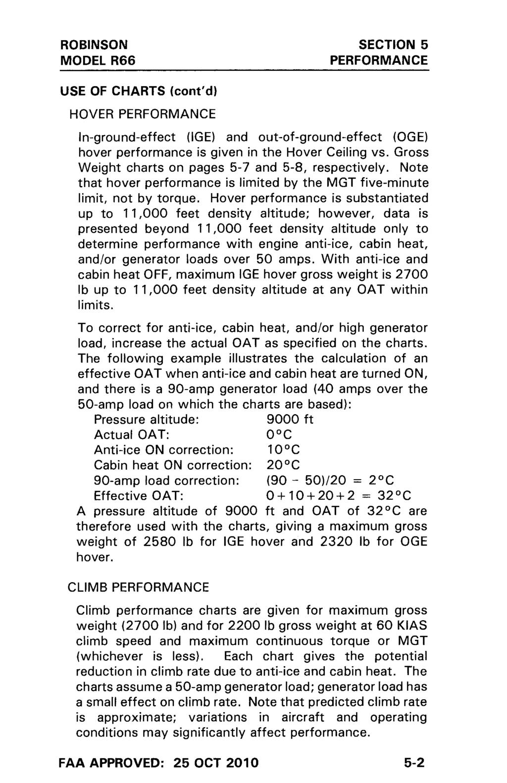
77 SECTION 5 PERFORMANCE FAA APPROVED: 26 NOV
78
79
80 INTENTIONALLY BLANK
81
82
83
84
85
86
87
88
89 SECTION 7 SYSTEMS DESCRIPTION SECTION 7 SYSTEMS DESCRIPTION CONTENTS Page General Rotor Systems Drive System Powerplant Installation Flight Controls Removable Flight Controls Hydraulic System Control Friction Adjustment Engine Controls Engine Anti-Ice Starter and Ignition System Fuel System Electrical System Lighting System External Power Receptacle Instrument Panel Annunciator Panel Dual Tachometer Audio System Optional Avionics Pitot-Static System Engine Monitoring Unit Cabin Heating and Ventilation Seats, Belts, and Baggage Landing Gear Rotor Brake Emergency Locator Transmitter (Optional) Optional Accessory Mounts REVISED: 29 AUG i
90 INTENTIONALLY BLANK
91 SECTION 7 SYSTEMS DESCRIPTION GENERAL SECTION 7 SYSTEMS DESCRIPTION The R66 is a five-place, single main rotor, single engine helicopter constructed primarily of metal and equipped with skid-type landing gear. The primary fuselage structure is welded steel tubing and riveted aluminum sheet. The tailcone is a monocoque structure in which aluminum skins carry most primary loads. Fiberglass and thermoplastics are used in secondary cabin structure and in various ducts and fairings. The cabin doors are also constructed of fiberglass and thermoplastics. Several cowl doors provide access to the drive system, engine, engine oil tank, fuel filler cap, and fuel sump drain. A right-side door provides access to the main baggage compartment. Additional access to controls and other components for maintenance is provided by removable panels and cowlings. The engine is located aft of the main baggage compartment. The engine compartment is isolated from the rest of the airframe by firewalls in front of and above the engine. The four cabin doors are removable. Refer to Section 8 for removal and installation procedures. REVISED: 20 JAN
92 SECTION 7 SYSTEMS DESCRIPTION ROTOR SYSTEMS The main rotor has two all-metal blades mounted to the hub by coning hinges. The hub is mounted to the shaft by a teeter hinge. The coning and teeter hinges use selflubricated bearings. Droop stops for the main rotor blades provide a teeter hinge friction restraint which normally prevents the rotor from teetering while starting or stopping. Pitch change bearings for each blade are enclosed in a housing at the blade root. The housing is filled with oil and sealed with an elastomeric boot. Each blade has a thick stainless steel spar at the leading edge which is resistant to corrosion and erosion. Aluminum skins are bonded to the spar approximately one inch aft of the leading edge. Blades must be refinished if the paint erodes to bare metal at the skin-to-spar bond line. Bond may be damaged if bond line is exposed. The tail rotor has two all-metal blades and a teetering hub with a fixed coning angle. The pitch change bearings have self-lubricated liners. The teeter hinge bearings are elastomeric. The tail rotor blades are constructed with aluminum skins and root fittings. Maintaining the paint finish will reduce corrosion and erosion. REVISED: 20 JAN
93 SECTION 7 SYSTEMS DESCRIPTION DRIVE SYSTEM The engine is mounted in a 37 nose-up attitude. A spragtype overrunning clutch mates directly to the splined engine power take-off (PTO) shaft. The clutch is connected to a shaft with flexible couplings at both ends to transmit power to the main gearbox. A ring and pinion spiral bevel gearset at the main gearbox input reduces speed to tail rotor driveline RPM. A second ring and pinion stage reduces speed from tail rotor driveline RPM to main rotor RPM. The tail rotor drive line consists of an intermediate shaft running aft from the main gearbox and a long tail rotor driveshaft which runs the length of the tailcone. Flexible couplings are located at both ends of the intermediate shaft. The long tail rotor driveshaft has a support bearing at its front end and a damper bearing approximately onethird of the way aft on the shaft. The cooling fan is mounted to the intermediate shaft. The tail gearbox contains a single 90 splash-lubricated spiral-bevel gearset which increases speed to tail rotor RPM. The main gearbox is pressure lubricated. The oil is pumped through an airframe-mounted filter and cooled by an oil cooler which receives its airflow from the cooling fan. The main gearbox also drives the flight control hydraulic pump. ISSUED: 25 OCT
94 SECTION 7 SYSTEMS DESCRIPTION POWERPLANT INSTALLATION One Rolls-Royce model 250-C300/A1 (commercial designation RR300) free-turbine turboshaft engine powers the helicopter. The engine is equipped with an ignition exciter, igniter, starter-generator, two tachometer senders, and additional powerplant instrument senders. See sections 1 and 2 for power plant specifications and limitations. A direct-drive, squirrel-cage style cooling fan is mounted to the intermediate shaft and supplies cooling air to the engine and gearbox oil coolers. Induction air enters through multiple openings in the upper fuselage cowlings and flows into a plenum forward of the firewall. The plenum contains a radial-flow air filter at the engine compressor inlet. The standard filter element is foam. A high-efficiency filter element with pleated media is optional. The high-efficiency filter includes a sight gage inside the upper left cowl door which provides an indication of filter dirt load. NOTE The high-efficiency filter is recommended for operating in dusty conditions. The standard filter may not filter fine sand or dust, resulting in reduced engine life. If the air filter becomes blocked, spring-loaded doors at the front of the filter housing open, allowing unfiltered air to the engine. The AIR FILTER annunciator illuminates when filter bypass is occurring. NOTE Periodically performing power assurance checks may provide indication of engine deterioration or air filter blockage. Maintenance actions such as air filter cleaning and compressor wash should be performed if aircraft fails power assurance check (see Section 5 for power assurance check and Maintenance Manual for maintenance procedures). REVISED: 29 AUG
95 SECTION 7 SYSTEMS DESCRIPTION POWERPLANT INSTALLATION (cont d) A temperature switch is mounted to the firewall above the engine to detect a fire in the engine compartment. Abnormally high temperature causes the ENGINE FIRE annunciator to illuminate. FLIGHT CONTROLS Dual controls are standard equipment and all primary controls are actuated through push-pull tubes and bellcranks. Bearings used throughout the control system are either sealed ball bearings which do not require lubrication or have self-lubricated liners. Flight control operation is conventional. The cyclic is center mounted with the left and right control grips mounted to a cross tube which pivots on the center cyclic post. On later aircraft, the pilot s cyclic grip angle can be adjusted fore and aft relative to the cross tube by a mechanic to achieve the most comfortable hand position. The most forward position provides the most control clearance at aft cyclic for larger pilots. Pilots should always verify the ability to apply full control travel prior to flight. The collective stick has a twist grip to provide input to the engine fuel control. Raising or lowering collective provides power turbine governor inputs via an interconnecting linkage. Right-side tail rotor pedals are adjustable. To adjust, remove quick-release pin on each pedal by depressing button and pulling. Slide pedal fore or aft to most comfortable of three adjustment positions and reinstall quick-release pin. Verify pins are secure before flight. REVISED: 29 AUG
96 SECTION 7 SYSTEMS DESCRIPTION REMOVABLE FLIGHT CONTROLS Left seat pilot controls may be removed and installed by maintenance personnel or pilots as follows: 1. To remove cyclic grip, remove quick-release pin by depressing button and pulling, then pull outward on left grip while supporting cyclic center post. Rotate rightside cyclic cross tube clockwise to stop, depress stop pin under cyclic pivot, and continue clockwise rotation one turn to wind up balance spring. To install removable cyclic grip, use reverse procedure. NOTE Later aircraft have a knurled ring next to the quick-release pin which may be hand tightened to eliminate freeplay. The ring must be loose (rotate counterclockwise looking inboard) to remove pin. CAUTION Overrotating cyclic cross tube in either wound or unwound direction will damage balance spring. CAUTION After removing cyclic grip, place plastic cap on exposed cyclic cross tube to prevent possible injury to left seat passenger. 2. To remove collective, push boot aft to expose locking pins. Depress locking pins and pull forward on stick. To install, use reverse procedure. It may be necessary to rotate stick slightly to allow pins to snap into place. CAUTION When collective is installed, ensure that both locking pins are fully engaged through holes on each side. 3. To remove tail rotor pedals, depress locking pin while twisting pedal counterclockwise, then pull up. To install, use reverse procedure. A cover which is stowed under the floor scuff plate may be rotated up to cover the floor openings when the pedals are removed. REVISED: 21 FEB
97
98 SECTION 7 SYSTEMS DESCRIPTION CONTROL FRICTION ADJUSTMENT Cyclic and collective controls are equipped with adjustable friction devices. The collective friction lever is located near the aft end of the pilot s collective. It is actuated aft to increase friction and forward to release it. The cyclic friction knob is located left of the cyclic stick. Turning the knob clockwise applies friction to both longitudinal and lateral cyclic. CAUTION Control friction must be used with caution in flight. Excessive friction may make the helicopter difficult to control. The pedals actuate push-pull controls connected directly to the tail rotor pitch control and do not incorporate any friction devices. An elastomeric trim spring provides a left pedal force to balance feedback forces in flight. ENGINE CONTROLS A twist grip throttle control is located on each collective stick. The controls are interconnected and actuate the engine fuel control input lever via a push-pull cable. The throttle is normally not used for control but is set either fully closed (idle position) or fully open. The engine incorporates a hydromechanical governor which attempts to maintain 100% engine output shaft RPM when the throttle is in the open position. A linkage provides the power turbine governor with collective inputs to help anticipate changing power demands. Large power changes or varying environmental conditions may cause the governor RPM setting to vary by a few percent. A momentary toggle switch (beep switch) on the collective stick is provided to trim, or beep, the governor setting to the desired RPM. The switch controls an actuator which adjusts the linkage between the collective and power turbine governor. Holding the beep switch up or down will change rotor RPM approximately one percent per two seconds. REVISED: 20 JAN
99
100
101 SECTION 7 SYSTEMS DESCRIPTION FUEL SYSTEM A single bladder-type crash-resistant fuel cell supplies fuel via gravity flow to the engine. The fuel cell incorporates vent fittings, a filler port, a fuel gage sender, a low-fuel sender, a sump drain, and a finger strainer at the fuel outlet. The low-fuel sender activates the LOW FUEL annunciator, indicating approximately five gallons or usable fuel remaining. The fuel cell is secured inside an aluminum structure. The filler cap is located under a cowl door. The left and right vent fittings are interconnected and are vented though two risers within the mast fairing. The vent fittings each have a rollover valve to prevent fuel leakage in any attitude. A fuel valve is located on the forward side of the firewall and is controlled by a push-pull cable control at the base of the pilot s collective stick. The engine incorporates a fuel pump assembly with an inlet filter. A differential pressure switch illuminates the FUEL FILTER annunciator if the filter becomes contaminated. A single drain allows fuel sampling from the low point in the fuel cell. The drain tube is accessible via a left side cowl door. The drain is opened by extending the plastic tube clear of the aircraft and pushing up on the drain. On later helicopters, a glass tube stowed inside the upper left cowl door is provided which may be used to catch fuel samples. ELECTRICAL SYSTEM A 28-volt DC electrical system is standard. Primary system components are a sealed lead-acid battery, a startergenerator, and a generator control unit. The battery is located in a compartment in the left side of the baggage compartment. The circuit breaker panel is on the ledge just forward of the left front seat. Breakers are marked to indicate function and amperage. Inflight reset of circuit breakers is not recommended. REVISED: 29 AUG
102 SECTION 7 SYSTEMS DESCRIPTION ELECTRICAL SYSTEM (cont d) The battery switch controls the battery relay which connects the battery to the electrical system. A wire protected by a fuse near the battery bypasses the battery relay to allow the tachometers and clock to receive battery power with the battery switch OFF. The avionics switch controls power to avionics. This allows avionics to be switched OFF via a single switch. Having sensitive electrical equipment off when the generator is switched ON protects against voltage spikes. An ammeter indicates total generator output. A digital voltmeter which reads main bus voltage at the circuit breaker panel is incorporated as part of the OAT indicator. Normal indication is 27.3 to 28.7 volts with the generator ON. A generator control unit (GCU) controls starter-generator function. Below 58 percent N 1 RPM, the GCU is in start mode regardless of generator switch position. Above 58 percent, the GCU automatically switches to generate mode. The generator switch should normally be off for starting to prevent applying generator load to the engine before reaching idle RPM. If the GEN annunciator illuminates in flight, turn off nonessential electrical equipment and switch generator to reset and then ON. If the GEN annunciator remains illuminated, land as soon as practical. NOTE A GEN light may indicate a broken generator shaft. With a broken shaft, it will not be possible to re-start the helicopter after shutdown. REVISED: 29 AUG
103 SECTION 7 SYSTEMS DESCRIPTION ELECTRICAL SYSTEM (cont d) ELECTRICAL SYSTEM REVISED: 20 JAN
104 SECTION 7 SYSTEMS DESCRIPTION ELECTRICAL SYSTEM (cont d) CIRCUIT BREAKER PANEL TYPICAL REVISED: 20 JAN
105 SECTION 7 SYSTEMS DESCRIPTION LIGHTING SYSTEM A red anti-collision light is installed on the tailcone and is controlled by the strobe switch. Position lights are installed on each side of the cabin and in the tail and are controlled by the nav lights switch. A light at the top of the windshield and post lights illuminate the instrument panel. Panel lighting is active when the nav lights switch is on and lighting is dimmed via the knob above the nav lights switch. An overhead map light mounted on a swivel is controlled by an adjacent switch with high and low settings. The map light may be used for emergency lighting of the instrument panel. An additional cabin light with an adjacent switch is located just aft of the map light. The map and cabin lights are not connected to the dimmer circuit. Two long-life, high intensity discharge (HID) landing lights are installed in the nose. One wide-angle and one narrowbeam light are used to increase lighted area. One landing light switch controls both lights and is located on the cyclic center post. NOTE Continuous operation of landing and position lights in flight is recommended to promote collision avoidance. An optional flashing light may be mounted on the tailcone in addition to the standard anti-collision light. On earlier aircraft, the optional light is controlled by an additional position on the strobe switch. On later aircraft, the optional light is controlled by a separate switch. REVISED: 26 NOV
106 SECTION 7 SYSTEMS DESCRIPTION EXTERNAL POWER RECEPTACLE A 28-volt MS3506-compatible receptacle is provided for external power. On earlier aircraft, the receptacle is located inside the right engine cowl door. On later aircraft, the receptacle is located in the cabin outboard of the pilot s seat. When the battery is switched on, the external power relay and the battery relay both close, connecting external power to the aircraft electrical system and battery. The external power relay will not close if reverse polarity is sensed by the receptacle. Provisions are provided to allow battery charging when the battery switch is off. See Section 8 for charging procedures. INSTRUMENT PANEL Standard primary instruments include an airspeed indicator, engine (N 2 ) and rotor dual tachometer, altimeter, torque meter, and magnetic compass. Engine gages include an N 1 tachometer, measured gas (turbine) temperature, oil pressure, oil temperature, and fuel quantity. Also standard are a clock, an ammeter, a digital outside air temperature gage/voltmeter, and an hourmeter. An additional hourmeter is located outboard of the pilot s seat. Both hourmeters require main gearbox oil pressure to activate. The outboard hourmeter is collective activated and may be used to determine time in service. Views of typical instrument panels are given on the following pages. Pilots should familiarize themselves with panel layout and equipment installations for each specific aircraft that they fly. For instrument panels with electronic flight displays, a P/N D327 light filter may be used to reduce reflections in the windshield at night. The light filter is installed by clipping it to the front of the display. Filter use is at pilot discretion. REVISED: 9 OCT
107 SECTION 7 SYSTEMS DESCRIPTION 1. VERTICAL SPEED INDICATOR 18. PANEL LIGHTS DIMMER 2. OPTIONAL INSTRUMENT 19. NAVIGATION LIGHTS SWITCH 3. AIRSPEED INDICATOR 20. STROBE LIGHT SWITCH 4. N 2 AND ROTOR TACHOMETERS 21. AVIONICS MASTER SWITCH 5. ALTIMETER 22. GENERATOR SWITCH 6. OPTIONAL INSTRUMENT 23. BATTERY SWITCH 7. TORQUEMETER 24. IGNITER SWITCH 8. ANNUNCIATOR PANEL 25. CABIN AIR 9. ANNUNCIATOR TEST BUTTON 26. OUTSIDE AIR TEMP/VOLTMETER 10. CLOCK 27. HOURMETER 11. ENGINE OIL TEMP GAGE 28. FUEL CUTOFF WITH GUARD 12. ENGINE OIL PRESSURE GAGE 29. AUDIO CONTROL PANEL 13. AMMETER 30. CYCLIC FRICTION 14. FUEL GAGE 31. CABIN HEAT 15. MGT GAGE 32. ELT SWITCH (OPTIONAL) 16. N 1 TACHOMETER 33. ANTI-ICE SWITCH 17. ROTOR BRAKE LIGHT 34. HEATED PITOT SWITCH (OPT L) INSTRUMENT PANEL TYPICAL (EARLIER AIRCRAFT) (Exact panel configuration may vary with optional equipment and date of helicopter manufacture.) REVISED: 26 NOV
108 SECTION 7 SYSTEMS DESCRIPTION 1. VERTICAL SPEED INDICATOR 20. IGNITER SWITCH 2. OPTIONAL INSTRUMENT 21. MGT GAGE 3. AIRSPEED INDICATOR 22. N 1 TACHOMETER 4. N 2 AND ROTOR TACHOMETERS 23. CABIN AIR 5. OPTIONAL INSTRUMENT 24. NAVIGATION LIGHTS SWITCH 6. OPTIONAL INSTRUMENT 25. ANTI-COLLISION LIGHT SWITCH 7. ALTIMETER 26. AVIONICS MASTER SWITCH 8. TORQUEMETER 27. GENERATOR SWITCH 9. CLOCK 28. BATTERY SWITCH 10. ANNUNCIATOR PANEL 29. FUEL CUTOFF WITH GUARD 11. ANNUNCIATOR TEST BUTTON 30. AUDIO CONTROL 12. PILOT S SIDE CONSOLE (OPT L) 31. AVIONICS STACK 13. AMMETER 32. HOURMETER 14. ENGINE OIL TEMP GAGE 33. CYCLIC FRICTION 15. OUTSIDE AIR TEMP/VOLTMETER 34. CABIN HEAT 16. ENGINE OIL PRESSURE GAGE 35. ELT SWITCH (OPTIONAL) 17. PANEL LIGHTS DIMMER 36. PITOT HEAT SWITCH (OPT L) 18. FUEL GAGE 37. ENGINE ANTI-ICE SWITCH 19. ROTOR BRAKE LIGHT INSTRUMENT PANEL TYPICAL (LATER AIRCRAFT) (Exact panel configuration may vary with optional equipment and date of helicopter manufacture.) REVISED: 26 NOV
109 SECTION 7 SYSTEMS DESCRIPTION 1. AIRSPEED INDICATOR 19. GPS NAVIGATOR 2. N 2 AND ROTOR TACHOMETERS 20. IGNITER SWITCH 3. ALTIMETER 21. ROTOR BRAKE ANNUNCIATOR 4. TORQUEMETER 22. CABIN AIR 5. MULTI-FUNCTION DISPLAY 23. NAVIGATION LIGHTS SWITCH 6. ANNUNCIATOR PANEL 24. ANTI-COLLISION LIGHT SWITCH 7. ANNUNCIATOR TEST BUTTON 25. AVIONICS MASTER SWITCH 8. PRIMARY FLIGHT DISPLAY 26. GENERATOR SWITCH 9. OPTIONAL INSTRUMENT 27. BATTERY SWITCH 10. CLOCK 28. FUEL CUTOFF WITH GUARD 11. AMMETER 29. AUDIO CONTROL 12. OUTSIDE AIR TEMP/VOLTMETER 30. AVIONICS STACK 13. PANEL LIGHTS DIMMER 31. HOURMETER 14. ENGINE OIL TEMP GAGE 32. CYCLIC FRICTION 15. MGT GAGE 33. CABIN HEAT 16. ENGINE OIL PRESSURE GAGE 34. ELT SWITCH (OPTIONAL) 17. FUEL GAGE 35. PITOT HEAT SWITCH (OPT L) 18. N 1 TACHOMETER 36. ENGINE ANTI-ICE SWITCH OPTIONAL INSTRUMENT PANEL (Exact panel configuration may vary with optional equipment and date of helicopter manufacture.) REVISED: 20 JAN
110 SECTION 7 SYSTEMS DESCRIPTION ANNUNCIATOR PANEL The annunciator panel consists of illuminated segments located at the top of the main instrument panel. If a caution or warning condition occurs, the appropriate segment(s) illuminate indicating the nature of the problem. The CHIP segments are illuminated by magnetic chip detectors in each gearbox which collect metallic particles in order to complete an electric circuit. The engine gearbox has two chip detectors, either of which can illuminate the ENGINE CHIP segment. The MR TEMP/PRESS segment is illuminated by either the temperature switch or oil pressure switch at the main gearbox. The ENGINE FIRE segment is illuminated by a temperature switch in the engine compartment. The ENGINE OIL segment is activated by a pressure switch which is independent of the oil pressure sender. The ANTI ICE segment illuminates via a pressure switch in the engine anti-ice air line. The GEN segment illuminates when the generator is disconnected from the main electrical bus. The LOW FUEL segment is illuminated by a float switch in the tank which is independent of the fuel quantity sender. The FUEL FILTER segment illuminates when a pressure switch detects excessive pressure drop across the fuel filter. The LOW RPM segment is illuminated by a sensor measuring driveline speed at the aft end of the main gearbox. A horn sounds simultaneously with illumination of the LOW RPM segment when rotor speed is below 95% RPM. The horn is disabled when the collective is fully down. The COWL DOOR segment is illuminated when the fuel filler cowl door, the baggage door, or, on earlier aircraft, the right engine cowl door (which accesses the external power receptacle) is not closed. The AIR FILTER segment illuminates when pressure drop across the filter opens bypass doors, allowing unfiltered air to the engine. REVISED: 20 JAN
111 SECTION 7 SYSTEMS DESCRIPTION ANNUNCIATOR PANEL (cont d) The EMU (Engine Monitoring Unit) segment indicates the EMU status with either steady, flashing, or no illumination. The EMU segment will illuminate only when the test button is depressed. A push-to-test button on the instrument panel should cause all segments on the annunciator panel, as well as the ROTOR BRAKE light, to illuminate when depressed. The LOW FUEL segment takes approximately two seconds before it illuminates due to a time delay in the circuit. (The time delay prevents sloshing fuel from giving a false indication.) If the LOW FUEL segment illuminates immediately after the test button is depressed, a fault is indicated and should be investigated by a qualified mechanic. The EMU segment takes approximately ten seconds to perform a self-test after the battery is switched ON before it will illuminate. The test button may be used on the ground or in flight to verify all circuits are functioning. DUAL TACHOMETER An electronic engine (N 2 ) and rotor dual tachometer is standard. Engine tachometer signal is provided by a transducer on the engine gearbox. Rotor tachometer signal is provided by magnetic senders at the main gearbox tail rotor driveline yoke. Each tachometer is on a separate circuit with its own circuit breaker. The tachometer bus receives power from the avionics bus or through the battery relay bypass circuit as long as the main rotor gearbox has oil pressure. Therefore, the tachometers will receive power through the bypass circuit whenever the rotors are turning even if the avionics bus is not powered. The bypass circuit is disconnected from the tachometer bus when the annunciator test button is depressed. Pressing the test button while the helicopter is running will confirm that the tachometers are receiving power from the avionics bus. REVISED: 20 JAN
112 SECTION 7 SYSTEMS DESCRIPTION AUDIO SYSTEM A five-place audio system is standard. An audio control panel allows control of communication radios, intercom, and music (or other external audio) input. Audio control panels from several manufacturers are offered. Pilots should consult the manufacturer s operating instructions for the specific brand of audio panel in the aircraft they fly. Headset jacks are located in the ceiling near each seat. Pilot and copilot intercom and transmit are controlled by trigger switches on the cyclic grips. The trigger has two detents; the first detent activates the intercom and the second detent transmits. Additional intercom buttons are located on the forward side of the rear seats and on the left forward floor or seat support. Intercom may also be set to be voice activated. Music or other external audio may be plugged into a jack on the circuit breaker panel. For most installations and settings, this input is muted during radio communication. OPTIONAL AVIONICS A wide range of optional avionics are available for the R66. It is not practical to provide a description of all equipment in this manual. All aircraft are delivered with the manufacturers operating manuals for each piece of installed equipment. Pilots are referred to the manufacturers manuals for detailed operating instructions. Good practice dictates becoming familiar with installed equipment before operating an aircraft. REVISED: 19 OCT
113 SECTION 7 SYSTEMS DESCRIPTION PITOT-STATIC SYSTEM The pitot-static system supplies air pressure to operate the airspeed indicator, altimeter, and vertical speed indicator. The pitot tube is located on the leading edge of the mast fairing. The static sources are located on each side of the cabin aft of the rear doors. Water can be drained from pitot-static lines by removing the plastic drain plugs which are accessible though the aft inspection panel on the underside of the cabin. Draining lines should be required only if the airspeed indicator or altimeter appear erratic. Pitot and static sources should be inspected frequently to verify no bugs or other obstructions. ENGINE MONITORING UNIT The Engine Monitoring Unit (EMU) is a digital recording device mounted behind the right rear seatback panel. The EMU continuously monitors N 1, N 2, engine torque, and MGT. EMU status is indicated by the EMU segment on the annunciator panel. The EMU segment will only illuminate while the annunciator panel test button is depressed. The EMU requires approximately ten seconds to complete a self-test after the aircraft battery is switched on. Once the self-test is complete, steady illumination of the annunciator means normal EMU operation. A slowly flashing indication (once every two seconds) or no illumination means there is a fault in the EMU s senders or circuitry. A fast flashing indication (four times per second) is given if the EMU has detected an exceedance. A fault or exceedance indication should be investigated and reset by a qualified mechanic prior to the next flight. The EMU records exceedances of Rolls-Royce engine limits. The EMU also records a start cycle when N 1 exceeds 30% and MGT is at least 343 C. EMU data can be downloaded to a computer with the appropriate software. The EMU is intended to be used only as a maintenance aid. It is the pilot s responsibility to report any observed exceedances and the operator s responsibility to maintain a record of engine starts and time in service. REVISED: 29 AUG
114 SECTION 7 SYSTEMS DESCRIPTION CABIN HEATING AND VENTILATION Fresh air vents are located in each door and in the nose. Door vents are opened and closed using the knob near the vent door hinge. A rotating knob is provided to seal and lock vents closed. For maximum ventilation, open door vents wide during hover but only one inch or less during cruise. The rotating knob can be used to hold vents partially open. The fresh air inlet in the nose is opened by pulling the vent handle on the console face. Rotating the vent handle clockwise will lock its position. Air from the nose inlet is directed along the inside surface of the windshield for defogging as well as for ventilation. Bleed air from the engine compressor is used for cabin heat. Tubing routes hot air from the engine to outlets forward of the tail rotor pedals and in the rear footwells. A heater control knob located to the left of the cyclic stick actuates a valve in the aft end of the control tunnel through a pushpull cable to control cabin heat. Because the cabin heat uses engine compressor air, some performance degradation occurs with heat ON (see Section 5). CAUTION In case of engine fire, cabin heat should be turned OFF. REVISED: 20 JAN
115 SECTION 7 SYSTEMS DESCRIPTION SEATS, BELTS, AND BAGGAGE The seats are not adjustable but the pilot-side pedals are adjustable. Each helicopter is supplied with a cushion which can be placed behind the pilot to position him farther forward. This allows shorter pilots to reach the pedals, the cyclic grip in its most forward position, and the controls on the center console. Each seat is equipped with a combined lap belt and inertia reel shoulder strap. The inertia reel is normally free but will lock if there is sudden movement as would occur in an accident. Five-point harnesses are optional for the front seats. The lap belts on these harnesses should be adjusted to eliminate slack. The lower strap should be adjusted as necessary to ensure that the buckle does not interfere with the cyclic grip at aft cyclic. The harness is equipped with a webbing stop located above the inertia reel. The stop limits shoulder strap retraction and should be adjusted so the straps are comfortable without excessive slack. The main baggage compartment is located between the cabin and the engine compartment. It is accessed via a large door on the aircraft right side. The cowl door annunciator illuminates to warn the pilot when the door is not latched. A light illuminates the compartment when the battery switch is ON. Tie down anchors are provided for securing items in the baggage compartment. Observe placarded weight limits. Additional compartments are located under each seat except the center rear seat. Seat cushions hinge forward for access to these compartments. Do not load these compartments above the maximum fill lines. The lines indicate required crush space for the seats in an accident. REVISED: 20 JAN
116 SECTION 7 SYSTEMS DESCRIPTION LANDING GEAR A skid-type landing gear is used. Most hard landings will be absorbed elastically. However, in an extremely hard landing, the struts will hinge up and outward as the crosstube yields (becomes permanently bent) to absorb the impact. Slight crosstube yielding is acceptable. However, yielding which allows the tail skid to be within 38 inches of the ground (30 inches for extended gear) when the helicopter is sitting empty on level pavement requires crosstube replacement. The four landing gear struts are fitted with aerodynamic fairings to reduce air drag. The helicopter is approved to fly with or without the fairings installed. Abrasion-resistant wear shoes are mounted on the bottom of the skids. These shoes should be inspected periodically, particularly if autorotation landings with ground contact have been performed. Have skid shoes replaced whenever the thinnest point in the wear area is less than 0.06 inches (1.5 mm). REVISED: 20 JAN
117 SECTION 7 SYSTEMS DESCRIPTION ROTOR BRAKE The rotor brake is mounted on the aft end of the main gearbox and is actuated by a cable connected to a pull handle located on the cabin ceiling. To stop the rotor, use the following procedure: 1. After pulling fuel cutoff, wait at least one minute. 2. Pull brake handle forward and down using moderate force (approximately 10 lb). 3. After rotor stops, it is recommended to use the rotor brake as a parking brake by hooking bead chain in slot in bracket. An annunciator light near the igniter switch illuminates when the brake is engaged. The brake must be released before starting the engine. When the brake is engaged, the starter is disabled. CAUTION Applying rotor brake without waiting at least one minute after engine shutdown or using a force which stops rotor in less than ten seconds may damage brake shoes. REVISED: 20 JAN
118 SECTION 7 SYSTEMS DESCRIPTION EMERGENCY LOCATOR TRANSMITTER (OPTIONAL) The Emergency Locator Transmitter (ELT) installation consists of a transmitter with internal battery pack, an external antenna, and a remote switch/annunciator. The transmitter is mounted to the upper steel tube frame and is accessible through the spring loaded air intake door in the right-side cowl. The remote switch/annunciator is located left of the cyclic stick. The ELT is operated by a switch on the transmitter and by the remote switch. The transmitter switch has been set in the ARM position at installation and should always be in this position for flight. The remote switch/annunciator is a three position switch with indicator light. This switch should be in the ARMED position for flight. With both switches set to armed, the ELT will begin transmitting when subjected to a high G load. When the unit is transmitting, the red indicator light illuminates. Moving the remote switch to ON activates the transmitter. Use the ON position if an emergency landing is imminent and time permits. If the ELT is inadvertently activated, use the momentary RESET & TEST position of the remote switch to stop transmission and reset the unit. The red indicator will extinguish when unit is reset. For more detailed instructions on ELT operation, maintenance, and required tests, refer to manufacturer s manual supplied with the unit. REVISED: 20 JAN
119 SECTION 7 SYSTEMS DESCRIPTION OPTIONAL ACCESSORY MOUNTS Provisions for mounting small, portable items are an option. The provisions use mounting bars located forward of the pilot s seat, the copilot s seat, or both. The bars are fitted with one or more clamp assemblies which are compatible with a variety of commercially available accessory mounts. There is a 10 lb total weight limit for items attached to each bar. USB and cigarette-lighter-style power outlets are installed near the inboard end of the mounting bars. The power outlets are protected by the Aux Power circuit breaker and in-line fuses and are placarded with voltage/ current ratings. Wire clamps and a pocket for securing excess wire are also provided. The accessory mounts are intended to provide a safe means of mounting small items such as portable electronic devices. The mounting bar, clamp assembly, and power outlets are approved as part of the aircraft type design, but any items attached are the responsibility of the pilot in command under appropriate operating rules. Ensure that any items attached are secure and do not interfere with flight controls or primary field of view. Route any wires through the wire clamps or secure them to the bar with cable ties or tape. ISSUED: 20 JAN
120 SECTION 7 SYSTEMS DESCRIPTION THIS PAGE INTENTIONALLY BLANK ISSUED: 20 JAN
121 SECTION 8 HANDLING AND MAINTENANCE SECTION 8 HANDLING AND MAINTENANCE CONTENTS Page General Required Documents Recording Time in Service Required Inspections Preventive Maintenance by the Pilot Alterations to Aircraft Ground Handling Parking Cabin Doors Engine Oil and Filter Gearbox Oil and Filter Hydraulic Fluid Air Filter Compressor Rinse and Wash Fuel Battery Fire Extinguisher (Optional) Cleaning Helicopter REVISED: 29 AUG i
122 INTENTIONALLY BLANK
123 SECTION 8 HANDLING AND MAINTENANCE GENERAL SECTION 8 HANDLING AND MAINTENANCE This section outlines procedures recommended for handling, servicing, and maintaining the R66 helicopter. Every owner should stay in close contact with a Robinson Service Center to obtain the latest service and maintenance information. Owners should also be registered with the factory to receive service bulletins, changes to this handbook, and other helpful information as it becomes available. Federal Regulations place responsibility for maintenance of a helicopter on the owner and operator. The owner/ operator must insure that all maintenance is performed by qualified mechanics and in accordance with the R66 Maintenance Manual (Instructions for Continued Airworthiness), Service Bulletins/Service Letters, and FAA Airworthiness Directives. All limits, procedures, safety practices, time limits, servicing, and maintenance requirements contained in this handbook are considered mandatory. Authorized Robinson Service Centers will have recommended modification, service, and operating procedures issued by the FAA and by Robinson Helicopter Company. This information will be useful in obtaining maximum utility and safety with the helicopter. REVISED: 20 JAN
124 SECTION 8 HANDLING AND MAINTENANCE REQUIRED DOCUMENTS The Airworthiness Certificate (FAA form ) must be displayed in the aircraft at all times. The following additional documents must be carried in the aircraft: 1. Registration Certificate (FAA Form ) 2. Pilot s Operating Handbook 3. Current Weight and Balance The following documents should not be carried in the aircraft, but must be available for use by any mechanic or pilot servicing the aircraft: 1. Aircraft Logbook 2. Engine Logbook NOTE Required documents may vary in countries other than the United States. RECORDING TIME IN SERVICE It is the operator s responsibility to maintain a record of time in service for the engine, airframe, and all life-limited components, as well as the number of start cycles for the engine. Two hourmeters are provided: the hourmeter on the console records all run time including ground idle and is provided for reference. The hourmeter located outboard of the pilot s seat is collective-activated and records run time only when the collective is raised off the down stop. The collective-activated hourmeter may be used to determine time in service for maintenance purposes, including time in service for all life-limited components. REVISED: 16 APR
125 SECTION 8 HANDLING AND MAINTENANCE REQUIRED INSPECTIONS Federal Regulations require most civil aircraft of U.S. registry to undergo a complete inspection every twelve months. This annual inspection must be signed off by a mechanic with Inspection Authorization (la). In addition to the annual inspection, the R66 Maintenance Manual requires a complete inspection after every 100 hours of operation. The helicopter incorporates a number of fatigue life-limited components which must be retired at specified time intervals. A list of these components is contained in the Airworthiness Limitations section of the R66 Maintenance Manual and Instructions for Continued Airworthiness. The engine also has life limits based on both time in service and start cycles. These limits are found in the RR300 Series Operation and Maintenance Manual (OMM). The R66 helicopter includes many unique features. Without special training, Airframe and Powerplant (A&P) mechanics are not qualified to perform the above inspections. These inspections must be performed only by properly rated personnel who have successfully completed a factoryapproved maintenance course of instruction on the R66 helicopter. The factory occasionally publishes Service Bulletins and the Federal Aviation Administration (FAA) occasionally publishes Airworthiness Directives (ADs) that apply to specific groups of aircraft. They are mandatory changes or inspections which must be complied with within the time limit specified. Owners should periodically check with Robinson Service Centers to be sure that the latest Service Bulletins and ADs issued have been complied with. REVISED: 20 JAN
126
127
128 SECTION 8 HANDLING AND MAINTENANCE GROUND HANDLING For leveling, hoisting, or jacking, see appropriate sections of the maintenance manual. The helicopter may be maneuvered on the ground using ground handling wheels. Ground handling wheels are attached inboard of the landing gear skid tubes forward of the rear struts. Recommended tire pressure is 60 psi (4 bar). Wheels must be removed for flight. To attach wheels: 1. Hold handle and wheel with protruding spindle in its lowest position. 2. Insert spindle into support mounted on skid. Make sure spindle is all the way in. 3. Pull handle over center to raise helicopter and lock wheel in position. CAUTION When lowering helicopter, handle has a tendency to snap over. Ground handling generally requires two people: one to hold the tail down and steer by holding the tail rotor gearbox and a second to push on the fuselage. Keep feet clear of skid tubes. Alternately, a Robinson electric tow cart may be used per the instructions provided. CAUTION Do not move helicopter by gripping tail rotor guard, outboard part of horizontal stabilizer, tail rotor, or tail rotor controls. REVISED: 20 JAN
129 SECTION 8 HANDLING AND MAINTENANCE PARKING 1. Place cyclic control in neutral and apply friction. 2. Put collective full down and apply friction. 3. Align rotor blades approximately fore and aft. Apply rotor brake. Use blade tie-downs in windy conditions. CAUTION If using rotor blade tie-downs, do not overtighten tie-down straps (5 lb max tension). Do not pull down on blades to teeter rotor. To lower a blade, push up on opposite blade. 4. During storm conditions, helicopter should be hangared or moved to a safe area. CABIN DOORS All four cabin doors may be removed and installed by maintenance personnel or pilots. To remove a door, disconnect door strut by lifting inboard end of strut while holding door in full open position, remove cotter rings in upper and lower hinge pins, and then lift door off. To install doors, use reverse procedure. Adjust weight and balance as required when removing or installing doors. REVISED: 20 JAN
130 SECTION 8 HANDLING AND MAINTENANCE ENGINE OIL AND FILTER Full oil quantity is six quarts and minimum quantity for takeoff is four quarts. Quantity is indicated as follows: Six quart indication is top of knurled section of dipstick. Four quart indication is bottom of knurled section of dipstick or center of oil tank sight gage. Engine oil change intervals have been designed to coincide with aircraft inspection intervals. Additional oil changes should not normally be required. Only turbine engine oil per specification AS 5780 HPC is approved. The following products are known to meet the specification and are approved by Rolls-Royce. Product Mobil Jet Oil (MJO) 254 British Petroleum Turbine Oil (BPTO) 2197 Manufacturer Exxon Mobil Lubricants Air BP Lubricants The engine oil filter is located on top of the engine and is accessible via a right side cowl door. A red indicator pin (impending bypass indicator) extends from the end of the filter housing if the filter becomes contaminated. Operation with a contaminated filter may allow oil to bypass the filter element. Oil will still be supplied to the engine but will be unfiltered. If erroneous indication is suspected, the bypass indicator may be reset by pushing it back in. If the indicator extends during next engine run or flight, service the filter. Refer to RR300 Series Operation and Maintenance Manual for servicing instructions. REVISED: 19 OCT
131 SECTION 8 HANDLING AND MAINTENANCE GEARBOX OIL AND FILTER Main and tail gearbox oil quantities are indicated by sight glasses. The main gearbox sight glass is on the left side of the gearbox and can be viewed by opening a left side cowl door. A light activated by a switch at the door illuminates the sight glass. The tail gearbox sight glass is located at the aft end of the tail gearbox. Both gearboxes use Robinson P/N A oil. Both gearboxes should be filled to center of sight glass with helicopter sitting level. A filler plug is provided on top of each gearbox. See R66 Maintenance Manual for oil addition instructions. The main gearbox filter is located in the gearbox compartment and is accessible via a left side cowl door. A red indicator pin (impending bypass indicator) extends from the end of the filter housing if the filter becomes contaminated. Operation with a contaminated filter may allow oil to bypass the filter element. Oil will still be supplied to the gearbox but will be unfiltered. If erroneous indication is suspected, the bypass indicator may be reset by pushing it back in. If indicator extends during next run-up or flight, service filter. Refer to R66 Maintenance Manual for servicing instructions. ISSUED: 25 OCT
132 SECTION 8 HANDLING AND MAINTENANCE HYDRAULIC FLUID Hydraulic fluid level is indicated by a sight gage in the reservoir. The sight gage can be viewed by opening a left side cowl door. A light activated by a switch at the door illuminates the sight gage. A filler/vent cap is located on top of the reservoir. If hydraulic fluid is not visible in the reservoir sight gage with helicopter sitting level, add Robinson part number A fluid (MIL-PRF-5606) per R66 Maintenance Manual. AIR FILTER NOTE Sight gage reading will be higher with system hot. The engine air filter element may be removed for cleaning as required. The standard foam filter element should be cleaned when visibly dirty or when contamination is indicated by the AIR FILTER annunciator. It should be replaced if foam is visibly damaged or deteriorated. The optional high-efficiency pleated-element filter should be cleaned if the sight gage indicator approaches the red line. It should also be cleaned and replaced per the schedule provided in the R66 Maintenance Manual. Servicing procedures for both styles of filter are provided in the Maintenance Manual. NOTE The high-efficiency filter is recommended for operating in dusty conditions. The foam filter may not filter fine sand or dust, resulting in reduced engine life. COMPRESSOR RINSE AND WASH The engine requires periodic compressor rinses when operated in a corrosive atmosphere. Compressor washes must be completed at specified intervals or when engine performance is not satisfactory. Refer to R66 Maintenance Manual for compressor rinse and compressor wash procedures and recommended intervals. REVISED: 29 AUG
133 SECTION 8 HANDLING AND MAINTENANCE FUEL Approved fuel grades and capacity are given in Section 2. The aircraft should be electrically grounded prior to fueling. Grounding provisions are provided inside the fuel filler cowl door for a grounding clip or an M83413/4-1 style plug. Attach the ground cable before removing the filler cap. On later helicopters, a fuel quantity dipstick is stowed inside the fuel filler cowl door. The dipstick is used by fully inserting it into fuel tank until the handle rests on the filler port, then blocking the vent hole on top of the handle and lifting it out of the tank far enough to see the fuel level in the tube. The dipstick indicates usable fuel quantity in U.S. gallons and is accurate only when the helicopter is parked on level ground. The dipstick will read high if the left side of the aircraft is low. A quick drain located at the fuel tank low point is accessible via a cowl door on the left side of the aircraft. A small quantity of fuel should be drained using the quick drain prior to the first flight each day and after refueling. On later helicopters, a glass tube stowed inside the upper aft cowl door is provided which may be used to catch fuel samples. Drain enough fuel to remove any water or contaminants. If fuel contamination is suspected, continue to drain fuel until all contamination is eliminated. The engine is equipped with a fuel filter. A switch at the filter illuminates the FUEL FILTER annunciator if the filter becomes contaminated. Fuel will continue to flow to the engine with a contaminated filter but may bypass the filter element. Refer to RR300 Series Operation and Maintenance Manual for filter servicing instructions. REVISED: 29 AUG
134 SECTION 8 HANDLING AND MAINTENANCE BATTERY The 24-volt battery is located in a compartment in the left side of the baggage compartment. The battery is sealed and does not require fluid level checks. A discharged battery is NOT AIRWORTHY because it will not have the reserve capacity to operate the electrical system should the charging system fail in flight. The battery may be charged using the external power receptacle located inside the right engine cowl door. For charging currents less than 10 amps, power connected to the receptacle will flow directly to the battery without the aircraft battery switch ON. Later aircraft have a special receptacle for the Batteryminder charger (Robinson part number MT990-1 for 120-volt AC power or MT990-2 for 240-volt AC power). Use of this charger will ensure a fully-charged battery and will maximize battery life. For information on battery replacement or capacity checks, see R66 Maintenance Manual. FIRE EXTINGUISHER (OPTIONAL) The optional fire extinguisher (model RT-A400) should be weighed monthly to verify it contains a sufficient charge of extinguishing agent. Results should be recorded on the decal affixed to the extinguisher or in other maintenance records. Weight should not show a decrease of more than 3.2 grams per year or a total weight of less than 500 grams. The extinguisher is rated for a storage and operating temperature of 120 F (49 C). If operating conditions would expose extinguisher to higher temperatures (e.g. parking in the sun in a hot climate), remove extinguisher and store it in a cooler area between flights. REVISED: 29 AUG
135 SECTION 8 HANDLING AND MAINTENANCE CLEANING HELICOPTER CLEANING EXTERIOR INCLUDING ROTOR BLADES The helicopter should be washed with mild soap and water. Harsh abrasives, alkaline soaps, or detergents should not be used because they could scratch painted or plastic surfaces or could cause corrosion of metal. Cover areas where cleaning solution could cause damage. Use the following procedure: 1. Rinse away loose dirt and salt residue with water. 2. Apply cleaning solution with a soft cloth, sponge, or soft bristle brush. 3. To remove stubborn oil and grease, use a cloth dampened with aliphatic naphtha. 4. Rinse all surfaces thoroughly. 5. Apply carnauba wax to rotor blades and renew wax when water no longer beads on blade surface. Any good automotive wax may be used to preserve other painted surfaces. Soft cleaning cloths or a chamois should be used to prevent scratches when cleaning or polishing. CAUTION Never use high-pressure spray to clean helicopter. Never blow compressed air into main or tail rotor blade tip drain holes. CLEANING WINDSHIELD AND WINDOWS 1. Remove dirt, mud, and other loose particles from exterior surfaces with clean water. 2. Wash with mild soap and warm water or with aircraft plastic cleaner. Use a soft cloth or sponge in a straight back and forth motion. Do not rub harshly. 3. Remove oil and grease with a cloth moistened with isopropyl alcohol (rubbing alcohol) or aliphatic naphtha. REVISED: 19 OCT
136 SECTION 8 HANDLING AND MAINTENANCE CLEANING HELICOPTER (cont d) CLEANING WINDSHIELD AND WINDOWS (cont d) CAUTION Do not use gasoline, other alcohols, benzene, carbon tetrachloride, thinner, acetone, or window (glass) cleaning sprays. 4. After cleaning plastic surfaces, apply a thin coat of hard polishing wax. Rub lightly with a soft cloth. Do not use a circular motion. 5. Scratches can be removed by rubbing with jeweler s rouge followed by hand polishing with commercial plastic polish. Use a figure eight motion when polishing. CLEANING UPHOLSTERY AND SEATS 1. Vacuum and brush, then wipe with damp cloth. Dry immediately. 2. Soiled upholstery, except leather, may be cleaned with a good upholstery cleaner suitable for the material. Follow manufacturer s instructions. Avoid soaking or harsh rubbing. 3. Leather should be cleaned with saddle soap or a mild hard soap and water. CLEANING CARPETS Remove loose dirt with a whisk broom or vacuum. For soiled spots and stains, use nonflammable dry cleaning liquid. REVISED: 20 JAN
137 SECTION 9 SUPPLEMENTS SECTION 9 SUPPLEMENTS OPTIONAL EQUIPMENT SUPPLEMENTS Information contained in the following supplements applies only when the related equipment is installed. CONTENTS Page Heated Pitot Air Conditioning Pop-Out Floats Police Version ADS-B Equipment Autopilot Auxiliary Fuel Lithium-Ion Battery ENG Version NON-U.S. SUPPLEMENTS The following supplements contain additional information required by certain countries: Argentine Supplement Brazilian Supplement Canadian Supplement CIS Supplement EASA Supplement Ukrainian Supplement FAA APPROVED: 17 JAN i
138 INTENTIONALLY BLANK
139
140
141
142 INTENTIONALLY BLANK
143 SECTION 9 AIR CONDITIONING SUPPLEMENT FAA APPROVED R66 PILOT S OPERATING HANDBOOK AIR CONDITIONING SUPPLEMENT This supplement must be included in the FAA-approved Pilot s Operating Handbook when cabin air conditioning is installed. Information contained herein supplements or supersedes the basic manual only in those areas listed in this supplement. For limitations, procedures, and performance information not contained in this supplement, consult the basic Pilot s Operating Handbook. APPROVED BY: Manager, Flight Test Branch, ANM-160L Federal Aviation Administration, LAACO Transport Airplane Directorate DATE: LOG OF REVISIONS Page No. Date Page No. Date Oct 15 9 Oct 15 9 Oct * 9-2.5* 9-2.6* 25 Feb 11 9 Oct Feb 11 * Manufacturer s data, not FAA approved. REVISIONS APPROVED BY: Manager, Flight Test Branch ANM-160L Federal Aviation Administration Los Angeles Aircraft Certification Office, Transport Airplane Directorate DATE: 9-2.1
144 SECTION 9 AIR CONDITIONING SUPPLEMENT SECTION 1: GENERAL INTRODUCTION This supplement contains the changes and additional data applicable when cabin air conditioning is installed. SECTION 2: LIMITATIONS No change. SECTION 3: EMERGENCY PROCEDURES POWER FAILURE - GENERAL If time permits, switch air conditioning OFF to maximize glide performance. SECTION 4: NORMAL PROCEDURES BEFORE STARTING ENGINE Add: A/C switch OFF AIR CONDITIONING OPERATION Air conditioning is controlled by the toggle switch at the forward end of the overhead duct. The switch allows selection of OFF, LOW, and HIGH fan settings. The compressor is automatically engaged by switching the fan on. Each of the seven outlets may be directed as desired. NOTE Evaporator condensate drains from a tube through the aircraft belly. Water drainage during ground operation is normal. FAA APPROVED: 9 OCT
145 SECTION 9 AIR CONDITIONING SUPPLEMENT SECTION 5: PERFORMANCE IGE HOVER CEILING VS. GROSS WEIGHT With air conditioning on, add 2 C to OAT. OGE HOVER CEILING VS. GROSS WEIGHT With air conditioning on, add 2 C to OAT. CLIMB PERFORMANCE, 2700 LB (1225 KG) GROSS WEIGHT Air conditioning operation may reduce climb rate up to 50 ft/min. CLIMB PERFORMANCE, 2200 LB (998 KG) GROSS WEIGHT Air conditioning operation may reduce climb rate up to 60 ft/min. FAA APPROVED: 9 OCT
146
147 SECTION 9 AIR CONDITIONING SUPPLEMENT SECTION 8: HANDLING AND MAINTENANCE Standard automotive-style charge ports are located on the compressor. Normal charge is 2.25 lb (1.02 kg) R-134a refrigerant. Refer to R66 Maintenance Manual for complete system service procedures. CAUTION System must only be serviced by qualified personnel following R66 Maintenance Manual procedures. REVISED: 9 OCT
148
149 SECTION 9 POP-OUT FLOATS SUPPLEMENT FAA APPROVED R66 PILOT S OPERATING HANDBOOK POP-OUT FLOATS SUPPLEMENT This supplement must be included in the FAA-approved Pilot s Operating Handbook when pop-out floats are installed. Information contained herein supplements or supersedes the basic manual only in those areas listed in this supplement. For limitations, procedures, and performance information not contained in this supplement, consult the basic Pilot s Operating Handbook. APPROVED BY: Manager, Flight Test Branch ANM-160L Federal Aviation Administration Los Angeles Aircraft Certification Office, Transport Airplane Directorate DATE: LOG OF REVISIONS Page No. Date Page No. Date * Dec Dec Oct Dec Nov Oct Oct Nov Oct * * * * * 9 Oct Dec Nov Oct Oct Oct Dec Dec Oct 2015 * Manufacturer s data, not FAA approved. REVISIONS APPROVED BY: Manager, Flight Test Branch ANM-160L Federal Aviation Administration Los Angeles Aircraft Certification Office, Transport Airplane Directorate DATE: 9-3.1
150 SECTION 9 POP-OUT FLOATS SUPPLEMENT SECTION 1: GENERAL INTRODUCTION This supplement contains the changes and additional data applicable when pop-out floats are installed. Pop-out floats are intended for safety during over-water flights. Intentional (non-emergency) water landings for other than training purposes are not recommended. NOTE The pop-out floats are not certified for ditching. Some countries may prohibit certain over-water operations. REVISED: 19 DEC
151 SECTION 9 POP-OUT FLOATS SUPPLEMENT SECTION 2: LIMITATIONS AIRSPEED LIMITS NEVER-EXCEED AIRSPEED (V NE ) FLOATS STOWED All Weights Autorotation 130 KIAS 100 KIAS For V NE reductions with altitude and temperature, see placards on page ADDITIONAL AIRSPEED LIMITS 65 KIAS maximum above 83% torque. With floats stowed, 100 KIAS maximum with any combination of cabin doors removed. 80 KIAS maximum for float inflation. 80 KIAS maximum with floats inflated. 115 KIAS maximum with float system armed (safety catch in READY position). FAA APPROVED: 9 OCT
152 SECTION 9 POP-OUT FLOATS SUPPLEMENT SECTION 2: LIMITATIONS (cont d) WEIGHT LIMITS Maximum weight for intentional water operations 2200 lb (998 kg) FLIGHT AND MANEUVER LIMITATIONS Maximum altitude decrease with floats inflated is 4000 feet. CAUTION Altitude loss greater than 4000 feet may cause floats to lose shape and rigidity due to atmospheric pressure increase. Do not inflate floats above 4000 feet AGL. Intentional water operations at weights above 2200 lb (998 kg) are prohibited. Intentional water operations in waves greater than 1 foot (0.3 m), trough to crest, are prohibited. Water takeoff after an emergency water landing is prohibited unless waves are less than 1 foot (0.3 m), trough to crest, and there are no indications of damage. Subsequent flight is limited to ferrying to the nearest suitable area for inspection. KINDS OF OPERATION LIMITATIONS Except for an actual emergency, night operation with floats inflated is prohibited. INSTRUMENT MARKINGS AIRSPEED INDICATOR Green arc Yellow arc* Red cross-hatch Red line 0 to 110 KIAS 110 to 130 KIAS 100 KIAS 130 KIAS *Earlier airspeed indicators without yellow arc must have the following placard adjacent: DO NOT EXCEED 110 KIAS EXCEPT IN SMOOTH AIR FAA APPROVED: 19 DEC
153 SECTION 9 POP-OUT FLOATS SUPPLEMENT SECTION 2: LIMITATIONS (cont d) PLACARDS Adjacent to pilot s cyclic grip: Near inflation lever: DO NOT INFLATE FLOATS ABOVE 80 KIAS FAA APPROVED: 14 NOV
154 SECTION 9 POP-OUT FLOATS SUPPLEMENT SECTION 3: EMERGENCY PROCEDURES POWER FAILURE GENERAL CAUTION Lowering collective rapidly or applying excessive forward cyclic while helicopter is moving forward on water can cause floats to submerge and helicopter to nose over. CAUTION Float inflation may take up to three seconds. Squeeze inflation lever early enough to allow full inflation before water contact. POWER FAILURE ABOVE 500 FEET AGL Autorotation to land: Same as in basic manual. Autorotation to water: 1. Lower collective immediately to maintain rotor RPM. 2. Reduce airspeed to below 80 KIAS. 3. Adjust collective to keep RPM between 95 and 106% or apply full down collective if light weight prevents attaining above 95%. 4. If altitude permits, maneuver into wind. 5. Inflate floats. CAUTION Do not inflate floats above 80 KIAS. Do not exceed 80 KIAS with floats inflated. 6. At about 40 feet AGL, begin cyclic flare. 7. At about 8 feet AGL, apply forward cyclic and raise collective just before touchdown. Touch down in slight nose high attitude with nose straight ahead. 8. Maintain cyclic in touchdown position and do not lower collective full down until forward motion has stopped. FAA APPROVED: 9 OCT
155 SECTION 9 POP-OUT FLOATS SUPPLEMENT SECTION 3: EMERGENCY PROCEDURES (cont d) POWER FAILURE BETWEEN 8 FEET AND 500 FEET AGL Autorotation to land: Same as in basic manual. Autorotation to water: 1. Lower collective immediately to maintain rotor RPM. 2. Reduce airspeed to below 80 KIAS. 3. Adjust collective to keep RPM between 95 and 106% or apply full down collective if light weight prevents attaining above 95%. 4. If altitude permits, maneuver into wind. 5. Inflate floats. CAUTION Do not inflate floats above 80 KIAS. Do not exceed 80 KIAS with floats inflated. 6. Maintain airspeed until water is approached, then begin cyclic flare. 7. At about 8 feet AGL, apply forward cyclic and raise collective just before touchdown. Touch down in slight nose high attitude with nose straight ahead. 8. Maintain cyclic in touchdown position and do not lower collective full down until forward motion has stopped. FAA APPROVED: 9 OCT
156 SECTION 9 POP-OUT FLOATS SUPPLEMENT SECTION 3: EMERGENCY PROCEDURES (cont d) POWER FAILURE BELOW 8 FEET AGL Over land: Same as in basic manual. Over water: 1. Apply right pedal as required to prevent yawing. 2. Inflate floats. 3. Allow rotorcraft to settle. 4. Raise collective just before touchdown. MAXIMUM GLIDE DISTANCE CONFIGURATION Same as in basic manual except airspeed 80 KIAS with floats inflated. With floats inflated, best glide ratio is about 5.2:1 or one nautical mile per 1200 feet AGL. EMERGENCY WATER LANDING POWER OFF See procedures for power failures in this supplement. EMERGENCY WATER LANDING POWER ON 1. Reduce airspeed to below 80 KIAS. 2. Inflate floats. CAUTION Do not inflate floats above 80 KIAS. Do not exceed 80 KIAS with floats inflated. 3. Make normal approach and landing to water. FAA APPROVED: 14 NOV
157 SECTION 9 POP-OUT FLOATS SUPPLEMENT SECTION 4: NORMAL PROCEDURES DAILY OR PREFLIGHT CHECKS 9. Pop-Out Floats Check float and cover condition Check hose and fitting condition Check pressure in pressure cylinder Verify safety pin at pressure cylinder removed Set inflation lever safety READY or LOCKED as desired CAUTION Avoid night flight over water beyond autorotation distance to land. Height above water may be difficult to judge during a water landing. COLD WEATHER OPERATION When OAT is below -10 C, there may be insufficient charge in pressure cylinder for full float inflation. FLOAT INFLATION The red inflation lever located under the pilot s collective is equipped with a safety catch to prevent inadvertent float inflation. Prior to overwater flight, place the safety catch in the READY position. With the safety catch in the READY position, floats may be inflated by squeezing inflation lever. Over land, safety catch should be reset to LOCKED position. CAUTION Observe 115 KIAS speed limitation when safety catch is in READY position. FAA APPROVED: 9 OCT
158 SECTION 9 POP-OUT FLOATS SUPPLEMENT SECTION 4: NORMAL PROCEDURES (cont d) FLOAT INFLATION (cont d) CAUTION The pressure cylinder also has provisions for a safety pin at the valve on the cylinder neck. This safety pin is for use during maintenance and cylinder transport only and must be removed at all other times. NOTE Some flapping of float covers during flight with floats inflated is normal. To minimize wear, consider removing covers if an extended flight with inflated floats is required. FAA APPROVED: 9 OCT
159 SECTION 9 POP-OUT FLOATS SUPPLEMENT SECTION 4: NORMAL PROCEDURES (cont d) OPERATION ON WATER Intentional (non-emergency) operation on water is limited to maximum wave heights of 1 foot (0.3 m) (trough to crest). Maximum recommended water taxi speed is 5 knots. Some application of collective is required. Since the helicopter sits very low on water, it is likely that water will leak into the cabin. Intentional water landings should be limited to training. Avoid salt water if possible. There may be limited tail rotor clearance to water, particularly at aft CG. Also, even small waves may cause enough rocking to dip the tail rotor in the water. If tail rotor contact with water is suspected, have tail rotor inspected prior to further flight. (If no noticeable change in vibration occurs after suspected water contact, helicopter may be repositioned to nearest convenient inspection site.) CAUTION Except for actual emergencies, maximum weight for water operation is 2200 lb. CAUTION Engine thrust will cause helicopter to drift forward. Some application of collective with aft cyclic input is required to stop drift. CAUTION If starting or stopping rotor on water, ensure area is clear as helicopter can rotate one or more complete turns while tail rotor RPM is low. FAA APPROVED: 19 DEC
160 SECTION 9 POP-OUT FLOATS SUPPLEMENT SECTION 4: NORMAL PROCEDURES (cont d) PRACTICE AUTOROTATION WITH GROUND CONTACT Same as in basic manual. Autorotations with floats stowed should only be performed to a smooth, hard surface to avoid damage to floats. Touch-down autorotations with floats inflated are not recommended due to the possibility of damage to floats. PRACTICE AUTOROTATION TO WATER Autorotation to water with floats inflated is same as practice autorotation with ground contact in basic manual except touch down in slight nose high attitude with nose straight ahead. Maintain cyclic in touchdown position and do not lower collective full down until forward motion has stopped. CAUTION Lowering collective rapidly or applying excessive forward cyclic while helicopter is moving forward on water can cause floats to submerge and helicopter to nose over. CAUTION There may be limited tail rotor clearance to water, particularly at aft CG. Applying excessive aft cyclic may cause tail rotor to contact water. SHUTDOWN PROCEDURE Add: Inflation lever safety LOCKED FAA APPROVED: 14 NOV
161 SECTION 9 POP-OUT FLOATS SUPPLEMENT SECTION 5: PERFORMANCE CLIMB PERFORMANCE, 2700 LB (1225 KG) GROSS WEIGHT Stowed or inflated floats may reduce climb rate by as much as 250 feet per minute. CLIMB PERFORMANCE, 2200 LB (998 KG) GROSS WEIGHT Stowed or inflated floats may reduce climb rate by as much as 300 feet per minute. FAA APPROVED: 9 OCT
162 SECTION 9 POP-OUT FLOATS SUPPLEMENT SECTION 6: WEIGHT AND BALANCE WEIGHT AND BALANCE RECORD Basic empty weight and CG with pop-out float landing gear and pressure cylinder installed are included in the Weight and Balance Summary provided with the helicopter. If pressure cylinder is removed, update Weight and Balance Record. A charged pressure cylinder weighs 11.4 lb. The longitudinal arm of the cylinder is 79.6 inches from datum and the lateral arm is +8.3 inches from datum. SECTION 7: SYSTEMS DESCRIPTION The pop-out float system consists of inflatable floats stowed in protective covers along the skid tubes, a pressure cylinder located in the compartment under the right rear seat, flexible hoses from the cylinder to the floats, an inflation lever located on the pilot s collective, an enlarged stabilizer installed at the base of the lower vertical stabilizer, and an end plate installed at the tip of the horizontal stabilizer. Sealed inspection panels and drains with check valves are installed on the cabin belly. The pressure cylinder is of aluminum construction reinforced with carbon filament windings and is charged with helium. Proper pressure is indicated on a placard on the cylinder, and pressure can be checked using the gage on the cylinder valve. A safety catch on the inflation lever can be set to prevent inadvertent actuation. With the safety catch in the READY position, floats are inflated by squeezing firmly on the inflation lever. (Approximately 20 lb force is required.) Float inflation time is approximately 2-3 seconds. With the safety catch in the LOCKED position, the inflation lever is locked out. To operate the safety catch, push spring-loaded knob with thumb while rotating U-shaped pin with forefinger as shown in figure. REVISED: 9 OCT
163 SECTION 9 POP-OUT FLOATS SUPPLEMENT SECTION 7: SYSTEMS DESCRIPTION (cont d) REVISED: 9 OCT
164 SECTION 9 POP-OUT FLOATS SUPPLEMENT SECTION 7: SYSTEMS DESCRIPTION (cont d) The pop-out floats are intended for safety during overwater flights. They are not certified for ditching. NOTE Floats maintain full pressure for at least 1 hour after inflation and typically maintain shape for several hours. Monitor float pressure if helicopter remains on water for an extended period. Verify adequate pressure (approximately 0.5 to 2 psi) prior to takeoff after an extended period of inflation. NOTE Flotation stability has been substantiated for emergency water landings up to a significant wave height of 8 feet (2.4m) corresponding to World Meteorological Organization Sea State 4. However, due to random variations in real-world wind and wave conditions, there is always some chance of capsize. Be prepared to evacuate rapidly if necessary. REVISED: 19 DEC
165 SECTION 9 POP-OUT FLOATS SUPPLEMENT SECTION 8: HANDLING AND MAINTENANCE GROUND HANDLING With floats installed, special ground handling wheels (Robinson part number MT980-1 and MT980-2) are required. A safety pin is provided for installation at the pressure cylinder valve. This pin should be installed during maintenance and cylinder transport to prevent inadvertent pressure release. CAUTION With the safety pin installed, it is not possible to inflate the floats using the cockpit inflation lever. The safety pin is for use during maintenance and cylinder transport only and must be removed at all other times. FLOAT TUBES AND COVERS Immediately replace any damaged float tube cover to minimize chance of float damage. Inspect float tube condition after each inflation. Refer to R66 Maintenance Manual for periodic inspection, float repacking, and cylinder recharge instructions. CLEANING HELICOPTER Clean helicopter exterior per section 8 of the basic manual immediately following operation in salt water. Clean under-seat baggage compartments if damp. REVISED: 19 DEC
166 THIS PAGE INTENTIONALLY BLANK ISSUED: 9 OCT
167 SECTION 9 POLICE VERSION SUPPLEMENT FAA APPROVED R66 PILOT S OPERATING HANDBOOK POLICE VERSION SUPPLEMENT This supplement must be included in the FAA-approved Pilot s Operating Handbook when police equipment is installed. Information contained herein supplements or supersedes the basic manual only in those areas listed in this supplement. For limitations, procedures, and performance information not contained in this supplement, consult the basic Pilot s Operating Handbook. APPROVED BY: DATE: Page No * Manager, Flight Test Branch, ANM-160L Federal Aviation Administration, LAACO Transport Airplane Directorate LOG OF REVISIONS Date 19 DEC AUG DEC DEC DEC DEC 16 Page No * 9-4.8* 9-4.9* * * * * Manufacturer s data, not FAA approved. REVISIONS APPROVED BY: DATE: Date 10 AUG DEC DEC DEC DEC AUG 15 Manager, Flight Test Branch, ANM-160L Federal Aviation Administration, LAACO Transport Airplane Directorate 9-4.1
168 SECTION 9 POLICE VERSION SUPPLEMENT SECTION 1: GENERAL INTRODUCTION This supplement contains the changes and additional data applicable to the Police Version. The Police Version is equipped with a nose-mounted gyro-stablized infrared camera, a flat screen monitor for viewing camera images, a video recorder, and a bellymounted searchlight. Optional FM transceivers, a PA/ Siren, Lojack equipment, and a GPS mapping system may also be installed. A dedicated, non-essential electrical bus distributes power to police equipment, and extended landing gear provides additional ground clearance for the camera and searchlight. There are two cockpit configurations: the earlier configuration installed on aircraft prior to S/N 0602 and the later configuration installed on aircraft S/N 0602 and subsequent. See descriptions in Section 7 of this supplement. SECTION 2: LIMITATIONS AIRSPEED LIMITS NEVER-EXCEED AIRSPEED (V ne ) All weights Autorotation 130 KIAS 100 KIAS For V ne reductions with altitude and temperature, see placards on page FLIGHT AND MANEUVER LIMITATIONS For earlier cockpit configuration, pilot in command must occupy right seat (configuration defined in Section 7). FAA APPROVED: 10 AUG
169 SECTION 9 POLICE VERSION SUPPLEMENT SECTION 2: LIMITATIONS (cont d) INSTRUMENT MARKINGS AIRSPEED INDICATOR Green arc Yellow arc* Red cross-hatch Red line 0 to 110 KIAS 110 to 130 KIAS 100 KIAS 130 KIAS *Earlier airspeed indicators without yellow arc must have the following placard adjacent: DO NOT EXCEED 110 KIAS EXCEPT IN SMOOTH AIR PLACARDS Adjacent to pilot s cyclic grip: FAA APPROVED: 19 DEC
170 SECTION 9 POLICE VERSION SUPPLEMENT SECTION 2: LIMITATIONS (cont d) PLACARDS (cont d) Inside right rear under-seat compartment: NO STOWAGE On camera controller: STOW DURING TAXI, TAKEOFF, AND LANDING Inside main baggage compartment: CAUTION MAXIMUM DISTRIBUTED FLOOR LOAD: 50 LB/FT 2 (244 KG/M 2 ) MAXIMUM TOTAL COMPARTMENT LOAD: 250 LB (113 KG) SECTION 3: EMERGENCY PROCEDURES MAXIMUM GLIDE DISTANCE CONFIGURATION With police equipment installed, best glide ratio is about 5.1:1 or one nautical mile per 1200 feet AGL. MINIMUM RATE OF DESCENT CONFIGURATION With police equipment installed, minimum rate of descent is about 1400 feet per minute. Glide ratio is about 4.3:1 or one nautical mile per 1400 feet AGL. FAA APPROVED: 19 DEC
171 SECTION 9 POLICE VERSION SUPPLEMENT SECTION 4: NORMAL PROCEDURES DAILY OR PREFLIGHT CHECKS Add to item 2, Fuselage Right Side: Verify searchlight secure. Add to item 6, Fuselage Left Side: Verify siren secure. Add to item 7, Nose: Verify camera and fairing secure. TAKEOFF PROCEDURE Stow camera controller during taxi and takeoff. APPROACH AND LANDING Stow camera controller. NOTE Stow searchlight horizontally when not in use to minimize chance of damage during a hard landing. SECTION 5: PERFORMANCE CLIMB PERFORMANCE, 2700 LB GROSS WEIGHT Police equipment may reduce climb rate by as much as 160 ft/min. CLIMB PERFORMANCE, 2200 LB GROSS WEIGHT Police equipment may reduce climb rate by as much as 200 ft/min. FAA APPROVED: 19 DEC
172 SECTION 9 POLICE VERSION SUPPLEMENT SECTION 6: WEIGHT AND BALANCE CAUTION Removal of nose-mounted camera causes a large shift in CG of empty helicopter. Calculate weight and balance prior to flight with camera removed to assure aft CG limit is not exceeded. SECTION 7: SYSTEMS DESCRIPTION GENERAL The R66 is a four-place helicopter when police equipment is installed. Basic descriptions of police equipment and systems are given below. More detailed information can be found in manufacturer s documents supplied with individual pieces of equipment. FLIGHT CONTROLS For the earlier cockpit configuration, the cyclic control does not include the left side grip in order to prevent interference with the observers s LCD monitor. (Configurations are defined below.) INSTRUMENT PANEL There are two basic cockpit configurations as shown on the following page. The earlier configuration uses a modified cyclic control without a left-side grip because the flat screen monitor would interfere. The later configuration uses the standard cyclic control with a leftside grip. REVISED: 19 DEC
173 SECTION 9 POLICE VERSION SUPPLEMENT SECTION 7: SYSTEMS DESCRIPTION (cont d) EARLIER CONFIGURATION (some optional equipment shown) LATER CONFIGURATION (some optional equipment shown) REVISED: 10 AUG
174 SECTION 9 POLICE VERSION SUPPLEMENT SECTION 7: SYSTEMS DESCRIPTION (cont d) ELECTRICAL SYSTEM An additional circuit breaker panel on the ledge just forward of the pilot s seat contains all circuit breakers for police equipment. Depending on installed police options, the outboard section of the aft row of circuit breakers may be a 14-volt bus powered by a 28- to 14-volt converter. The police equipment master switch on the left side of the panel controls power to all police equipment. NOTE Police circuit breaker panel will not be powered by police equipment master switch unless avionics switch is also on. Wiring for police equipment is in a separate harness and occupies portions of the main baggage compartment, right side under seat compartments, and right rear footwell. Protective covers isolate the wiring harness as appropriate. AUDIO SYSTEM Audio control panel(s) to accommodate police radios and other equipment are installed. The audio system receives power from the audio breaker on the main (left hand) circuit breaker panel. It is not connected to the police equipment master switch. Intercom and transmit switches for the left front seat are provided on the floor near the observer s right heel. An optional transmit switch for the left rear seat is also available. The optional switch is handheld on a cord which plugs into a jack beneath the left rear seat ICS button. Transmit functionality is tied to the selection on the observer s audio panel. REVISED: 19 DEC
175 SECTION 9 POLICE VERSION SUPPLEMENT SECTION 7: SYSTEMS DESCRIPTION (cont d) SEATS, BELTS, AND BAGGAGE The center rear seat has been replaced with an arm rest and storage console. Baggage is not permitted in the right rear under-seat compartment due to electronic equipment and wiring in that compartment. An interior wall has been added to the main baggage compartment to create an electronic equipment compartment at the aft end. LANDING GEAR Extended forward landing gear struts provide additional ground clearance for the camera and searchlight. The ground clearance at the tail is reduced by approximately 8 inches with the helicopter parked. INFRARED CAMERA SYSTEM The infrared camera system consists of a gyro-stabilized, gimbal-mounted infrared/video camera in the chin and a power junction box in the main baggage compartment behind the interior wall. The camera is operated by the observer in the left front seat via a handheld controller. A tray and strap forward of the circuit breaker panel are provided for controller stowage when not in use. A flat screen LCD monitor is located in front of the left front seat to display camera images. For the earlier cockpit configuration, the monitor is equipped with a visor to minimize glare. The monitor mount is hinged to retract forward and down, out of the observer s way, when not in use. For the later cockpit configuration, the monitor has no visor but is easily dimmed using a knob on its front face. The monitor mount is hinged on its inboard edge, and the monitor folds back against the left side of the instrument console, out of the observer s way, when not in use. REVISED: 19 DEC
176 SECTION 9 POLICE VERSION SUPPLEMENT SECTION 7: SYSTEMS DESCRIPTION (cont d) DIGITAL VIDEO RECORDER The digital video recorder (DVR) is mounted just aft of the space between the front backrests and controlled by a switch at the observer s station. The DVR can record images from the camera and play them back on the LCD monitor. SEARCHLIGHT The searchlight is installed on a motorized gimbal under the belly. The searchlight power junction box is located in the right rear under-seat compartment. The searchlight is steerable in azimuth and elevation and is operated from the left front seat via a remote control. An optional slaving system allows the searchlight to be slaved to follow the camera. The searchlight should be stowed horizontally when not in use to minimize chance of damage during a hard landing. CAUTION The searchlight is very bright and can disorient other pilots or ground personnel at long distances. CAUTION The searchlight beam is hot. Exposure to the beam at close range for more than a few seconds can result in burns. INTERIOR LIGHT An additional observer-side interior light is operated via a momentary foot switch on the left-hand forward floor. Power is supplied to the interior light via the GAGES breaker in the left hand circuit breaker panel and is not disconnected by the police equipment master switch. REVISED: 19 DEC
177 SECTION 9 POLICE VERSION SUPPLEMENT SECTION 7: SYSTEMS DESCRIPTION (cont d) PA/SIREN SYSTEM (OPTIONAL) A 100-watt speaker is located on the aircraft belly near the left rear landing gear strut. The PA system control panel is located in the avionics stack and allows the pilot or observer to select PA, radio, yelp, or siren for broadcast through the speaker. FM TRANSCEIVERS (OPTIONAL) A multi-band FM transceiver may be mounted either next to the LCD monitor or in the main avionics stack. The FM transceiver band(s) are selectable from the audio control panel(s). LOJACK (OPTIONAL) The Lojack installation consists of a receiver installed in the main baggage compartment behind the interior wall, a display and control unit on the right side of the instrument console, and four belly-mounted stub antennas. Lojack is used to track stolen vehicles equipped with Lojack transmitters. GPS MAPPING SYSTEM (OPTIONAL) The GPS mapping computer is installed in the main baggage compartment behind the interior wall and allows an overhead view of the helicopter s area of operation to be displayed on the LCD monitor. The computer contains a database of streets, landmarks, and topography enabling direct navigation to street addresses and other points on the ground. The computer is accessed using a keyboard below the LCD monitor. An optional inertial monitoring unit can interface with the computer to keep the camera and/or searchlight trained on a fixed ground location while the helicopter maneuvers. SECTION 8: HANDLING AND MAINTENANCE No change. REVISED: 19 DEC
178 SECTION 9 POLICE VERSION SUPPLEMENT THIS PAGE INTENTIONALLY BLANK REVISED: 10 AUG

179 SECTION 9 ADS-B EQUIPMENT SUPPLEMENT FAA APPROVED R66 PILOT S OPERATING HANDBOOK ADS-B EQUIPMENT SUPPLEMENT This supplement must be included in the FAA-approved Pilot s Operating Handbook when ADS-B equipment is installed. The information contained herein supplements or supersedes the basic manual only in those areas listed in this supplement. For limitations, procedures, and performance information not contained in this supplement, consult the basic Pilot s Operating Handbook. APPROVED BY: DATE: Manager, Flight Test Branch, ANM-160L Federal Aviation Administration, LAACO Transport Airplane Directorate LOG OF REVISIONS Page No. Date Page No. Date * 9-5.3* 19 Oct Oct Oct * 19 Oct Oct Oct 16 *Manufacturer s data, not FAA approved. REVISIONS APPROVED BY: DATE: Manager, Flight Test Branch, ANM-160L Federal Aviation Administration, LAACO Transport Airplane Directorate 9-5.1
180 SECTION 9 ADS-B EQUIPMENT SUPPLEMENT SECTION 1: GENERAL INTRODUCTION This supplement contains the changes and additional data applicable when Automatic Dependent Surveillance- Broadcast (ADS-B) equipment is installed. ADS-B is divided into two categories ADS-B Out and ADS-B In. ADS-B Out equipment transmits information to air traffic control to supplement radar/transponder information. The supplemental information allows optimization of flight plan routes and aircraft spacing. ADS-B Out equipment may be required for operation in certain airspace. The R66 ADS-B Out installation has been shown to meet the requirements of 14 CFR NOTE The R66 ADS-B Out system operates on frequency 1090 MHz. This frequency is also accepted for ADS-B Out equipment in most countries outside the United States. The ADS-B Out equipment consists of either a GPS receiver connected to the transponder or a transponder with built-in GPS. The transponder has ADS-B broadcast capability and broadcasts GPS position as well as additional preprogrammed information such as aircraft identification and type to air traffic control. ADS-B In equipment receives traffic information from other ADS-B equipped aircraft. ADS-B In equipment may also receive additional traffic information and weather information from ground stations. The additional traffic and weather information from ground stations is only available in the United States. REVISED: 19 OCT
181 SECTION 9 ADS-B EQUIPMENT SUPPLEMENT SECTION 1: GENERAL (cont d) INTRODUCTION (cont d) The ADS-B In equipment consists of a receiver (either installed under the left, front seat or built in to the transponder) and a suitable display. Refer to receiver and display manufactures documentation for operation of ADS-B In equipment. The R66 may be equipped with only ADS-B Out or with both ADS-B Out and ADS-B In. REVISED: 19 OCT
182 SECTION 9 ADS-B EQUIPMENT SUPPLEMENT SECTION 2: LIMITATIONS PLACARDS On transponder when ADS-B Out equipment is installed: ADS-B OUT INSTALLED SECTION 3: EMERGENCY PROCEDURES No change. SECTION 4: NORMAL PROCEDURES ADS-B SYSTEM OPERATION ADS-B system operation is mostly automatic and requires little pilot action. The GPS (if separate from the transponder), transponder, and ADS-B receiver (if installed) must all be powered and in normal operating modes for proper system function. ADS-B OUT The R66 ADS-B Out system is a single point of entry system. Mode 3/A codes, IDENT commands, and emergency codes are set on the transponder and are automatically incorporated in ADS-B Out broadcasts. The transponder should transition to ALT mode after takeoff for proper ADS-B Out broadcasts. ADS-B Out broadcasts may be selected off by using menus associated with the transponder FUNC key. NOTE ADS-B Out may be required in certain airspace. Do not turn off ADS-B Out unless directed by air traffic control. Malfunctions in the ADS-B Out system are annunciated by various messages on the transponder and/or GPS screen (refer to manufacturers documentation). FAA APPROVED: 19 OCT
183 SECTION 4: SECTION 9 ADS-B EQUIPMENT SUPPLEMENT NORMAL PROCEDURES (cont d) ADS-B SYSTEM OPERATION (cont d) ADS-B IN The ADS-B In receiver is either mounted underneath the left, front seat or is built in to the transponder. The receiver is powered by the Transponder/ADS-B circuit breaker. ADS-B In data is sent from the receiver to a suitable display, often the primary GPS screen. The display may have dedicated traffic and weather views or may allow traffic and weather information to be overlaid on other data such as moving maps. Warnings such as traffic conflicts may also appear on the display. Refer to receiver and display manufacturers documentation. SECTION 5: PERFORMANCE No change. FAA APPROVED: 19 OCT
184 SECTION 9 ADS-B EQUIPMENT SUPPLEMENT SECTION 6: WEIGHT AND BALANCE No change. SECTION 7: SYSTEM DESCRIPTION ADS-B SYSTEM The ADS-B Out system consists of either a GPS receiver connected to the transponder or a transponder with built-in GPS. The transponder broadcasts the aircraft s position, identification, and certain other parameters to air traffic control. ADS-B data is broadcast via the Extended Squitter (ES) feature of the transponder on a frequency of 1090 MHz. Note that change of aircraft registration may require update of preprogrammed parameters by qualified maintenance personnel. Most of the data required for ADS-B broadcast such as aircraft type, ICAO address, and call sign are preprogrammed at installation. Flight-specific data such as Mode 3/A code and IDENT are entered using the transponder controls. The transponder uses these codes simultaneously for standard transponder as well as ADS-B broadcasts. There is no need to make a second code entry or to enter a code more than once. This is known as a single point of entry ADS-B system. The ADS-B In system consists of a receiver (either mounted under the left, front seat or built in to the transponder) and a suitable display. The receiver receives both approved US ADS-B frequencies (978 MHz and 1090 MHz). SECTION 8: No change. HANDLING, SERVICING AND MAINTENANCE REVISED: 19 OCT
185 SECTION 9 AUTOPILOT SUPPLEMENT FAA APPROVED R66 PILOT S OPERATING HANDBOOK AUTOPILOT SUPPLEMENT This supplement must be included in the FAA-approved Pilot s Operating Handbook when the autopilot is installed. The information contained herein supplements or supersedes the basic manual only in those areas listed in this supplement. For limitations, procedures, and performance information not contained in this supplement, consult the basic Pilot s Operating Handbook. APPROVED BY: DATE: Manager, Flight Test Branch, ANM-160L Federal Aviation Administration, LAACO Transport Airplane Directorate LOG OF REVISIONS Page No. Date Page No. Date * 9 Oct 15 9 Oct 15 9 Oct 15 9 Oct 15 9 Oct * 9-6.7* 9-6.8* 9-6.9* * 9 Oct 15 9 Oct 15 9 Oct 15 9 Oct 15 9 Oct 15 * Manufacturer s data, not FAA approved. REVISIONS APPROVED BY: DATE: Manager, Flight Test Branch, ANM-160L Federal Aviation Administration, LAACO Transport Airplane Directorate 9-6.1
186 SECTION 9 AUTOPILOT SUPPLEMENT SECTION 1: GENERAL INTRODUCTION This supplement contains the changes and additional data applicable when the autopilot is installed. CAUTION The autopilot is intended to enhance safety by reducing pilot workload. It is not a substitute for adequate pilot skill nor does it relieve the pilot of the responsibility to maintain adequate outside visual reference. The primary autopilot mode is Stability Augmentation System (SAS) mode which maintains a steady helicopter attitude by applying corrective inputs to the cyclic. The autopilot does not provide any collective or pedal inputs. Additional modes providing heading hold, altitude hold, and navigation functionality are also selectable. SECTION 2: LIMITATIONS FLIGHT AND MANEUVER LIMITATIONS Minimum altitude for use of autopilot ALT mode is 200 feet AGL. For practice instrument approaches, minimum altitude for use of autopilot VRT mode is 50 feet AGL. Pilot s hand must be on cyclic grip under the following conditions: During autopilot engagement or intentional disengagement At airspeeds less than 50 KIAS when less than 500 feet AGL FAA APPROVED: 9 OCT
187 SECTION 9 AUTOPILOT SUPPLEMENT SECTION 3: EMERGENCY PROCEDURES AUTOPILOT DISENGAGEMENT OR FAILURE The autopilot is designed to automatically disengage if the system detects a fault. Disengagement is indicated by four beeps in the headset. If the autopilot does not automatically disengage, failure may be recognized by erratic cyclic control motion, abnormal cyclic stick forces, or deviations in pitch or roll. 1. Continue flight using manual control. If autopilot has not disengaged, manually disengage using cyclic AP OFF button or control panel SAS button. 2. If SAS annunciator on control panel is steady white, re-engagement may be attempted at pilot s discretion. NOTE The system automatically switches off all modes except SAS mode at airspeeds below 44 KIAS or above 140 KIAS, accompanied by a single beep. This is by design and not a system failure. SECTION 4: NORMAL PROCEDURES GENERAL Autopilot controls and operating modes are described in Section 7, Systems Description. NOTE Cyclic friction must be fully off for autopilot to work properly. Cyclic friction will degrade autopilot performance. FAA APPROVED: 9 OCT
188 SECTION 9 AUTOPILOT SUPPLEMENT SECTION 4: NORMAL PROCEDURES STARTING ENGINE AND RUN-UP After Hydraulic system, add: Autopilot Check NOTE For autopilot check, wear headset and ensure cyclic friction is off. Engage SAS mode, and verify cyclic exhibits centering tendency and SAS annunciator on control panel turns green. Disengage. Verify 4 beeps in headset, cyclic reverts to normal hydraulic system feel, and SAS annunciator turns white. TAKEOFF PROCEDURE Autopilot SAS mode may be engaged as desired on the ground or at any time during the takeoff procedure. Retrim as necessary to eliminate undesirable cyclic forces. CRUISE Add: Engage autopilot modes as desired. In SAS mode, retrim as necessary to eliminate undesirable cyclic forces. CAUTION It is the pilot s responsibility to monitor flight controls, aircraft flightpath, traffic, and terrain even while the autopilot is engaged. Be prepared to take control if required. SECTION 5: PERFORMANCE No change. FAA APPROVED: 9 OCT
189 SECTION 9 AUTOPILOT SUPPLEMENT SECTION 6: WEIGHT AND BALANCE No change. SECTION 7: SYSTEMS DESCRIPTION AUTOPILOT The autopilot system consists of two electric servomotors, a flight control computer, an autopilot control panel, and control buttons on the cyclic grip. One servomotor controls pitch and is installed in the control tunnel forward of the cyclic stick. The other servomotor controls roll and is installed under the pilot s seat. The servomotors are connected to the cyclic through electromagnetic clutches. The flight control computer is installed on the forward panel under the pilot s seat, and the autopilot control panel is installed in the avionics stack. In addition to the autopilot system components, an onboard attitude source such as an Attitude Heading Reference System (AHRS) is required. The primary autopilot mode is Stability Augmentation System (SAS) mode which maintains a steady helicopter attitude by applying corrective inputs to the cyclic. This is felt as a light cyclic centering force. The autopilot senses aircraft attitude using a combination of sensors in the flight control computer and the onboard attitude source. The computer then sends signals to the servomotors which are connected to the bottom of the cyclic in the control tunnel. Additional modes may be layered on top of SAS mode and are described below. REVISED: 9 OCT
190 SECTION 9 AUTOPILOT SUPPLEMENT SECTION 7: SYSTEMS DESCRIPTION (cont d) AUTOPILOT (cont d) Heading Mode (HDG) maintains the heading selected by the heading bug on the directional gyro or Horizontal Situation Indicator (HSI) display. Aircraft can be steered using the heading bug. NOTE For large heading or course changes, the autopilot will use a maximum of 20 bank. Altitude Mode (ALT) maintains altitude at the time of engagement or of last TRIM button release. The target altitude is reset each time the TRIM button is pressed and released. NOTE The autopilot uses pitch attitude to maintain altitude or follow an approach glidepath. It does not have any control of power setting. The pilot must manage power with the collective to control speed and rate of climb or descent. Make small, smooth power changes to allow the system to adjust to new power settings. Navigation Mode (NAV) tracks the active GPS or VLOC course displayed on the Course Deviation Indicator (CDI). If no CDI is installed, NAV will only track the active GPS course displayed on the GPS. NAV may be armed prior to intercepting the active course. NAV annunciator is white when NAV is armed and turns green at course intercept. If HDG is active when NAV is armed, the autopilot will fly the selected heading until course intercept. If HDG is not active, the autopilot will select a 45 intercept angle. REVISED: 9 OCT
191 SECTION 9 AUTOPILOT SUPPLEMENT SECTION 7: SYSTEMS DESCRIPTION (cont d) AUTOPILOT (cont d) Vertical Navigation Mode (VRT) tracks an ILS glideslope or GPS approach vertical guidance. Arm VRT (annunciator turns white when armed) prior to intercepting the glidepath. VRT annunciator will turn green at glidepath intercept. NOTE Pushing the ALT button while VRT is armed or active will turn off VRT. VRT must be rearmed or re-engaged as desired. NOTE Reducing power to approach setting just prior to glidepath intercept is recommended. Backcourse Mode (BC) reverse CDI sensing for backcourse approaches. Course on HSI should be set so that tail of course pointer points toward runway (set to inbound front course). The control panel has a row of buttons to control autopilot modes and annunciators to indicate mode status. A dark annunciator indicates that a mode is off, a white annunciator indicates that a mode is armed or on standby, and a green annunciator indicates that a mode is active. When the avionics master is switched on, the autopilot performs a self-test and then enters SAS standby mode. All of the control panel indicators flash alternating white and green during the self-test. Four headset beeps occur at the beginning of the self-test as a check of the aural warning function. The SAS annunciator on the control panel turns steady white when the self-test is complete. NOTE Autopilot will not enter standby mode if attitude indicator is not functioning or indicated bank angle is greater than 6 degrees. REVISED: 9 OCT
192 SECTION 9 AUTOPILOT SUPPLEMENT SECTION 7: SYSTEMS DESCRIPTION (cont d) AUTOPILOT (cont d) The autopilot SAS mode is engaged either by pressing the SAS button on the control panel or by pressing the TRIM button on the cyclic for more than 1.25 seconds. Additional modes are engaged by pressing the appropriate button on the control panel. The additional modes are disabled and will not engage at airspeeds below 44 KIAS or above 140 KIAS. To disengage any mode, push the appropriate button on the control panel. NOTE Disengaging SAS mode will also disengage all other modes. Modes may also be disengaged using the AP OFF button on the cyclic. If only SAS mode is engaged, push the AP OFF button once to disengage. If additional modes are engaged, push the AP OFF button once to disengage all modes except SAS and a second time to disengage SAS mode, or push and hold the AP OFF button to disengage all modes including SAS. NOTE SAS disengagement is always accompanied by four beeps in the headset. Safety monitors automatically disengage individual modes or the entire system if a fault is detected. Automatic disengagement of SAS mode (or the entire system) is indicated by four beeps in the headset. Automatic disengagement of any mode other than SAS is indicated by a single beep in the headset. There is no audio indication for intentional disengagement of modes other than SAS. REVISED: 9 OCT
193 SECTION 9 AUTOPILOT SUPPLEMENT SECTION 7: SYSTEMS DESCRIPTION (cont d) AUTOPILOT (cont d) NOTE The system also automatically reverts to SAS mode at airspeeds below 44 KIAS or above 140 KIAS, accompanied by a single beep. The TRIM button is used to re-set the target attitude (to re-trim) while in SAS mode. Use a small amount of force to override the autopilot and then push and release the TRIM button at the new desired condition. If the force to override is objectionable, the TRIM button may be held down during maneuvers. The system will re-trim to the attitude at which the TRIM button is released. NOTE The system will not re-trim to more than 6 nose down, 11 nose up, or 10 of bank. If a re-trim is attempted outside these limits, the system will trim to the limiting value. NOTE When engaging SAS mode from standby, the autopilot uses the helicopter attitude at the time SAS mode is engaged as the target (trim) attitude. For large pitch and roll angles at the time of engagement, a target of 2 nose up pitch and 0 (level) roll is used. The autopilot is protected by a dedicated circuit breaker on the avionics bus (autopilot is not powered with the avionics master switch off). REMOVABLE FLIGHT CONTROLS On later aircraft, disconnect the electrical connector for the left-hand trim button located near the quick release pin before removing the left cyclic grip. Reconnect the connector when installing the left cyclic grip. REVISED: 9 OCT
194 SECTION 9 AUTOPILOT SUPPLEMENT SECTION 8: HANDLING AND MAINTENANCE No change. SECTION 10: SAFETY TIPS The autopilot is intended to reduce pilot workload and enhance safety. It is important that pilots do not misuse this capability and allow their attention to be diverted from monitoring the helicopter attitude and looking for traffic and other obstacles. Autopilot disengagement requires immediate pilot attention. Pilots must always be prepared to take manual control. The autopilot is not certified for flight in Instrument Meteorological Conditions (IMC). Adhering to appropriate VFR weather minimums is essential for safety. If an inadvertent loss of outside visual reference occurs, the pilot must regain visual conditions as quickly as possible while avoiding abrupt, disorienting maneuvers. The following procedure is recommended: 1. If not already engaged, immediately engage autopilot SAS mode and allow autopilot to recover from unusual attitude if one has occurred. 2. Select a heading and altitude to ensure terrain and obstacle clearance. Turns and/or climbs may be required. Engage additional autopilot modes as desired for workload reduction. 3. While maintaining terrain and obstacle clearance, maneuver toward conditions of improved visibility. REVISED: 9 OCT
195 SECTION 9 AUXILIARY FUEL SUPPLEMENT FAA APPROVED R66 PILOT S OPERATING HANDBOOK AUXILIARY FUEL SUPPLEMENT This supplement must be included in the FAA-approved Pilot s Operating Handbook when the auxiliary fuel system is installed. Information contained herein supplements or supersedes the basic manual only in those areas listed in this supplement. For limitations, procedures, and performance information not contained in this supplement, consult the basic Pilot s Operating Handbook. APPROVED BY: Manager, Flight Test Branch ANM-160L Federal Aviation Administration Los Angeles Aircraft Certification Office, Transport Airplane Directorate DATE: LOG OF REVISIONS Page No. Date Page No. Date Oct Oct Feb Feb * 9-7.6* 9-7.7* 9-7.8* * Manufacturer s data, not FAA approved. 19 Oct Feb Feb Feb 2016 REVISIONS APPROVED BY: DATE: Manager, Flight Test Branch ANM-160L Federal Aviation Administration Los Angeles Aircraft Certification Office, Transport Airplane Directorate 9-7.1
196 SECTION 9 AUXILIARY FUEL SUPPLEMENT SECTION 1: GENERAL INTRODUCTION This supplement contains changes and additional data applicable when the auxiliary fuel system is installed. CAUTION When tank is full, auxiliary fuel system weighs over 320 lb (145 kg). Do not exceed helicopter weight limitations. SECTION 2: LIMITATIONS WEIGHT LIMITS Baggage compartment with auxiliary fuel tank installed: Maximum distributed load 50 lb/ft 2 (244 kg/m 2 ) Maximum total load 100 lb (45 kg) FUEL LIMITATIONS AUXILIARY FUEL CAPACITY Transferable to main tank: Non-transferable: 43.5 US gallons (165 liters) 0.14 US gallons (0.5 liters) NOTE Fuel in auxiliary tank is not usable fuel for flight planning purposes until it is transferred to the main tank. FAA APPROVED: 19 OCT
197 SECTION 9 AUXILIARY FUEL SUPPLEMENT SECTION 2: LIMITATIONS (cont d) PLACARDS Near auxiliary fuel tank filler cap: FUEL GRADE JET A, JET A1, JET B OR AS SPECIFIED IN PILOT S HANDBOOK ANTI-ICE ADDITIVE MAY BE REQUIRED SEE PILOT S HANDBOOK Inside main baggage compartment: CAUTION WITH AUX FUEL TANK INSTALLED: MAXIMUM DISTRIBUTED FLOOR LOAD: 50 LB/ FT 2 (244 KG/M 2 ) MAXIMUM TOTAL BAGGAGE LOAD: 100 LB (45 KG) WITHOUT AUX FUEL TANK INSTALLED: MAXIMUM DISTRIBUTED FLOOR LOAD: 50 LB/ FT 2 (244 KG/M 2 ) MAXIMUM TOTAL COMPARTMENT LOAD: 300 LB (136 KG) SECTION 3: EMERGENCY PROCEDURES AMBER CAUTION INDICATORS NO FLOW (on AUX FUEL panel) When transfer pump is switched on, indicates fuel is not transferring from auxiliary tank to main tank. When pump is first switched on, it is normal for light to illuminate for approximately 5 seconds while system is priming. Otherwise, light indicates either auxiliary tank is empty or transfer pump has failed. Switch pump off to extinguish light. NOTE Light also illuminates when quantity button is pressed to verify circuit is functioning. FAA APPROVED: 17 FEB
198 SECTION 9 AUXILIARY FUEL SUPPLEMENT SECTION 4: NORMAL PROCEDURES DAILY OR PREFLIGHT CHECKS Add to item 1, Pilot s Station: Verify aux fuel pump is off. While battery switch is ON, press QUANTITY button to check aux fuel quantity and verify NO FLOW light illuminates. Add to item 2, Fuselage Right Side: Verify aux fuel tank is secure and no leaks Verify aux fuel quantity and filler cap secure Sample aux fuel, drain water and contaminants Stow drain hose and latch baggage door BEFORE STARTING ENGINE Add: Aux fuel pump OFF AUX FUEL PUMP OPERATION After engine start, auxiliary fuel transfer pump may be turned on as desired. The aux fuel pump may be left on even when the main tank is full. Excess fuel is recirculated to the auxiliary tank. Switch aux fuel pump off when the auxiliary fuel tank is empty (indicated by the NO FLOW light). NOTE The fuel transfer system has no redundancy in case of pump failure. Therefore, fuel is not usable for flight planning purposes until it is transferred to the main tank. SHUTDOWN PROCEDURE Add: Aux fuel pump OFF SECTION 5: PERFORMANCE No change. FAA APPROVED: 17 FEB
199 SECTION 9 AUXILIARY FUEL SUPPLEMENT SECTION 6: WEIGHT AND BALANCE WEIGHT AND BALANCE RECORD Basic empty weight and CG with auxiliary fuel system installed is included in the Weight and Balance Summary provided with the helicopter. LOADING INSTRUCTIONS The following table may be used when calculating loaded helicopter weight and CG position. Item Weight (lb) Longitudinal arm (in.) Lateral arm (in.) (+ = right side) Auxiliary fuel Remove auxiliary fuel tank Remove auxiliary tank support tray CAUTION When tank is full, auxiliary fuel system weighs over 320 lb (145 kg). Do not exceed helicopter weight limitations. REVISED: 19 OCT
200 SECTION 9 AUXILIARY FUEL SUPPLEMENT SECTION 7: SYSTEMS DESCRIPTION The auxiliary fuel system consists of a removable fuel tank located in the forward section of the baggage compartment, hoses connecting the auxiliary tank to the main fuel tank, and a small control panel on the instrument console. The auxiliary fuel tank includes a crash-resistant bladder in an aluminum and fiberglass enclosure, an internal fuel transfer pump, a quantity sender, a filler port, and a sump drain. The filler port and sump drain are accessed by opening the baggage door. The tank mounts on a separate fiberglass tray which is also removable. The pump transfers fuel to the main tank at approximately 40 gallons per hour (150 liters per hour). Venting is provided through a second hose connected to the main tank. If the main tank is full, any excess fuel transferred by the pump returns to the auxiliary tank through the vent hose. A fuel flow sensor is located at the fitting where transferred auxiliary fuel enters the main tank (hose connection near the main tank filler port). The sensor illuminates the NO FLOW light on the control panel when the pump switch is on but the fuel transfer rate is less than ten gallons per hour. The AUX FUEL control panel on the console includes a pump switch, a NO FLOW annunciator light, and a QUANTITY button. The pump switch engages the transfer pump. When the pump switch is on, the NO FLOW light indicates fuel is not transferring from auxiliary tank to the main tank, either because the auxiliary tank is empty or the pump has failed. It is normal for the light to illuminate for approximately five seconds when the pump is first switched on while the system is priming. A time-delay circuit automatically switches the pump off if the NO FLOW light is illuminated for more than ten seconds. The light will remain on even after the time delay has removed power from the pump. Turning the pump switch off will extinguish the light. ISSUED: 17 FEB
201 SECTION 9 AUXILIARY FUEL SUPPLEMENT SECTION 7: SYSTEMS DESCRIPTION (cont d) While the QUANTITY button is depressed, the fuel quantity gage indicates fuel quantity in the auxiliary tank instead of the main tank. The NO FLOW light also comes on while the QUANTITY button is depressed to provide a test of the circuit and to confirm that the auxiliary tank quantity is being displayed on the fuel gage. The auxiliary fuel tank has two drains through the belly of the helicopter. Any fuel spilled at the filler port is collected by the surrounding scupper and drains through a hose into the outboard belly drain location. The tank support tray has a drain at the inboard drain location. Fuel leaking from the inboard drain indicates a possible leak in the fuel bladder. A sump drain hose stowed vertically along the right side of the tank allows preflight fuel sampling from the low point of the tank. To sample fuel, extend hose away from the helicopter and push in on the valve. The valve may be locked open to allow draining of the tank. Operationally, the fuel transfer pump may be switched on any time at the pilot s discretion. If the main tank is full, any excess fuel transferred from the auxiliary tank will return through the vent/return hose. Note that fuel in the auxiliary tank is not considered usable for flight planning purposes because the fuel transfer system has no redundancy in case of pump failure. The auxiliary fuel tank may be removed to provide additional baggage space. The separate support tray may also be removed. A small container which may be clipped to the outboard side of the tank is provided for stowing installation hardware. Refer to the R66 Maintenance Manual for removal and installation procedures. SECTION 8: HANDLING AND MAINTENANCE No change. ISSUED: 17 FEB
202 SECTION 9 AUXILIARY FUEL SUPPLEMENT INTENTIONALLY BLANK ISSUED: 17 FEB
203 SECTION 9 LITHIUM-ION BATTERY SUPPLEMENT FAA APPROVED R66 PILOT S OPERATING HANDBOOK LITHIUM-ION BATTERY SUPPLEMENT This supplement must be included in the FAA-approved Pilot s Operating Handbook when the lithium-ion main battery is installed. Information contained herein supplements or supersedes the basic manual only in those areas listed in this supplement. For limitations, procedures, and performance information not contained in this supplement, consult the basic Pilot s Operating Handbook. APPROVED BY: Manager, Flight Test Branch ANM-160L Federal Aviation Administration Los Angeles Aircraft Certification Office, Transport Airplane Directorate DATE: LOG OF REVISIONS Page No. Date Page No. Date Aug Jan Aug * 9-8.5* 9-8.6* * Manufacturer s data, not FAA approved. 29 Aug Aug Jan 2017 REVISIONS APPROVED BY: Manager, West Flight Test Section, AIR-716 Federal Aviation Administration Los Angeles, CA DATE: 9-8.1
204 SECTION 9 LITHIUM-ION BATTERY SUPPLEMENT SECTION 1: GENERAL INTRODUCTION This supplement contains changes and additional data applicable when the lithium-ion main battery is installed. SECTION 2: LIMITATIONS No change. SECTION 3: EMERGENCY PROCEDURES AMBER CAUTION INDICATORS BATT FAULT Indicates abnormal battery operation. Charging, discharging, or both may be disabled. Land as soon as practical. Generator will continue to supply power in flight. NOTE Battery s internal circuitry may disable charge/discharge functions due to overtemperature, over/under voltage, or excessive current draw. A flashing light means the fault may be recoverable (battery will reset itself) either when the condition improves or during a power cycle at the next landing. A steady light means battery maintenance or replacement will likely be necessary. FAA APPROVED: 17 JAN
205 SECTION 9 LITHIUM-ION BATTERY SUPPLEMENT SECTION 4: NORMAL PROCEDURES COLD WEATHER OPERATION The lithium-ion battery has a built-in heater, so battery preheating is not required. When the battery switch is ON, the BATT HEATER light illuminates during the heating cycle and extinguishes when the battery is warm enough to attempt a start. The indicator light is disabled after engine start, but the heater will continue to cycle as required to maintain optimum battery temperature. STARTING ENGINE AND RUN-UP After Battery Switch ON, add: Battery Heater Indicator Light...Extinguished STARTING ENGINE AND RUN-UP NOTE A battery without sufficient charge to start the engine will not have the normal indications of starter sluggishness associated with a lead-acid battery. Instead, the battery s monitoring circuit will suddenly interrupt power to the starter. If this occurs, immediately abort start by pulling fuel cutoff. SECTION 5: PERFORMANCE No change. SECTION 6: WEIGHT AND BALANCE No change. FAA APPROVED: 29 AUG
206 SECTION 9 LITHIUM-ION BATTERY SUPPLEMENT SECTION 7: SYSTEMS DESCRIPTION ELECTRICAL SYSTEM A 17 amp-hour lithium-ion battery replaces the lead-acid main battery. The battery includes built-in circuitry that monitors temperature, voltage, and current draw and manages battery charge and discharge. The circuitry automatically disables charge and/or discharge if any electrical or thermal problems are detected. The battery uses lithium-iron-phosphate chemistry which is less susceptible to thermal runaway than some other lithium battery chemistries. The metal battery case is designed to contain any heat or gases generated within the battery and is vented overboard on the left side of the aircraft. No venting should occur during normal operation. Two indicator lights, BATT FAULT and BATT HEATER, are installed to the left of the annunciator panel to show battery status. The annunciator panel test button should cause these lights to illuminate along with the rest of the annunciator panel. The indicator lights will also illuminate briefly when the battery switch is turned on after several hour of inactivity. The fault light illuminates if the battery has an over- or under-voltage condition, an over-temperature condition, or if current draw exceeds limits. A flashing light indicates a recoverable fault. The light may go out if the fault corrects itself (e.g. temperature decrease) or may go out as a result of a power cycle at the next landing. A steady light indicates battery maintenance or replacement may be required. The emergency procedure for a fault light (flashing or steady) is to land as soon as practical. The generator will continue to supply electrical power during the landing. REVISED: 29 AUG
207 SECTION 9 LITHIUM-ION BATTERY SUPPLEMENT SECTION 7: SYSTEMS DESCRIPTION (cont d) ELECTRICAL SYSTEM (cont d) The battery incorporates an internal heater for cold weather operation. The heater attempts to maintain a battery temperature of at least 50 F (10 C). When the battery is switched ON, the heater light illuminates while the heater is warming the battery and extinguishes when the battery is warm enough to attempt an engine start. On very cold days, the heating cycle may take 10 minutes or more. The heater light is disabled while the engine is running but the heater will continue to function as long as the battery switch is ON. If a start is attempted with insufficient charge, the battery s safety monitors may interrupt power. In the event of a power interruption, a small backup power supply will allow the MGT and N 1 gages as well as the Engine Monitoring Unit to continue functioning. The backup power supply also provides power to the map light. The backup power supply consists of two 9-volt batteries installed in the compartment under the left front seat. The 9-volt batteries are non-rechargeable and should be replaced periodically as indicated in the R66 Maintenance Manual. SECTION 8: HANDLING AND MAINTENANCE Nominal charge voltage for the lithium-ion battery is 28.8 volts. Some lead-acid chargers may not provide enough voltage to fully charge the battery. Ensure charging equipment is compatible with lithium-ion batteries. Refer to the R66 Maintenance Manual for additional handling and maintenance instructions. REVISED: 29 AUG
208 SECTION 9 LITHIUM-ION BATTERY SUPPLEMENT THIS PAGE INTENTIONALLY BLANK ISSUED: 17 JAN
209 SECTION 9 E.N.G. VERSION SUPPLEMENT FAA APPROVED R66 PILOT S OPERATING HANDBOOK ELECTRONIC NEWS GATHERING (E.N.G.) VERSION SUPPLEMENT This supplement must be included in the FAA-approved Pilot s Operating Handbook when Electronic News Gathering (E.N.G.) equipment is installed. Information contained herein supplements or supersedes the basic manual only in those areas listed in this supplement. For limitations, procedures, and performance information not contained in this supplement, consult the basic Pilot s Operating Handbook. APPROVED BY: DATE: Page No * * Manager, Flight Test Branch, ANM-160L Federal Aviation Administration, LAACO Transport Airplane Directorate LOG OF REVISIONS Date 30 Jun Jun Jun Jun Jun Jun Jun Jun 17 Page No * * * * * * * * Manufacturer s data, not FAA approved. Date 30 Jun Jun Jun Jun Jun Jun Jun
210 SECTION 9 E.N.G. VERSION SUPPLEMENT SECTION 1: GENERAL INTRODUCTION This supplement contains the changes and additional data applicable when Electronic News Gathering (E.N.G) equipment is installed. The E.N.G. version is equipped with a nose-mounted, gyro-stabilized video camera, microwave transmitting equipment, and related video and audio components to allow on-scene video and audio recording as well as relay of video and audio to ground stations. A rear center equipment console replaces the center rear seat and houses various audio and video controls. Extended landing gear provides additional ground clearance for the nose camera and belly-mounted microwave antenna. Typical crew configuration includes a camera operator who controls the news equipment from the left rear seat. E.N.G. equipment is described in detail in section 7. ISSUED: 30 JUN
211 SECTION 9 E.N.G. VERSION SUPPLEMENT SECTION 2: LIMITATIONS AIRSPEED LIMITS NEVER-EXCEED AIRSPEED (V ne ) All weights Autorotation 120 KIAS 100 KIAS For V ne reductions with altitude and temperature, see placards on page WEIGHT LIMITS Baggage Compartment: Maximum distributed floor load: 50 lb/ft 2 (244 kg/m 2 ) Maximum total baggage load: 250 lb (113 kg) FLIGHT AND MANEUVER LIMITATIONS Rear seat main monitor must be stowed below 500 feet AGL. Camera laptop controller must be stowed during taxi, takeoff, and landing. INSTRUMENT MARKINGS AIRSPEED INDICATOR Green arc Yellow arc Red cross hatch Red line 0 to 110 KIAS 110 to 120 KIAS 100 KIAS 120 KIAS FAA APPROVED: 30 JUN
212 SECTION 9 E.N.G. VERSION SUPPLEMENT SECTION 2: LIMITATIONS (cont d) PLACARDS Adjacent to pilot s cyclic grip: On rear seat main monitor: MONITOR MUST BE STOWED WHEN BELOW 500 FEET AGL On laptop camera controller: STOW DURING TAXI, TAKEOFF, AND LANDING Inside right rear under-seat compartment: NO STOWAGE Inside main baggage compartment: CAUTION MAXIMUM DISTRIBUTED FLOOR LOAD: 50 LB/FT 2 (244 KG/M 2 ) MAXIMUM TOTAL COMPARTMENT LOAD: 250 LB (113 KG) FAA APPROVED: 30 JUN
213 SECTION 9 E.N.G. VERSION SUPPLEMENT SECTION 3: EMERGENCY PROCEDURES POWER FAILURE ABOVE 500 FEET AGL Add: If time permits, stow main rear seat monitor and laptop controller. MAXIMUM GLIDE DISTANCE CONFIGURATION With E.N.G. equipment installed, best glide ratio is about 4.8:1 or one nautical mile per 1300 feet AGL. MINIMUM RATE OF DESCENT CONFIGURATION With E.N.G. equipment installed, minimum rate of descent is about 1600 feet per minute. Glide ratio is about 3.8:1 or one nautical mile per 1600 feet AGL. FAA APPROVED: 30 JUN
214 SECTION 9 E.N.G. VERSION SUPPLEMENT SECTION 4: NORMAL PROCEDURES DAILY OR PREFLIGHT CHECKS Add to item 3, Tailcone, Empennage, and Tail Rotor: Verify security of camera on horizontal stabilizer Add to item 4, Belly: Verify security of microwave antenna pod Add to item 7, Nose: Verify security of camera and fairing Add to item 8, Cabin area: Verify security or proper stowage of cameras, monitors, and control panels. CAUTION Talent lights and video monitors can be distracting for some pilots during dark, night conditions. Ensure proper crew coordination prior to switching on equipment, and set brightness levels to pilot preference. TAKEOFF PROCEDURE Add: Stow rear seat main monitor and laptop camera controller. DESCENT, APPROACH, AND LANDING Add: Stow rear seat main monitor and laptop camera controller. FAA APPROVED: 30 JUN
215 SECTION 9 E.N.G. VERSION SUPPLEMENT SECTION 5: PERFORMANCE CLIMB PERFORMANCE, 2700 LB GROSS WEIGHT E.N.G. equipment may reduce climb rate by as much as 350 ft/min. CLIMB PERFORMANCE, 2200 LB GROSS WEIGHT E.N.G. equipment may reduce climb rate by as much as 450 ft/min. FAA APPROVED: 30 JUN
216 SECTION 9 E.N.G. VERSION SUPPLEMENT SECTION 6: WEIGHT AND BALANCE CAUTION Removal of nose-mounted camera causes a large shift in CG of empty helicopter. Calculate weight and balance prior to flight with camera removed to assure aft CG limit is not exceeded. SECTION 7: SYSTEMS DESCRIPTION AIRFRAME The R66 is a four-place helicopter when E.N.G. equipment is installed. Basic descriptions of news gathering equipment and systems are given below. More detailed information can be found in manufacturer s documents supplied with individual pieces of equipment. ELECTRICAL SYSTEM An additional circuit breaker panel on the ledge just forward of the pilot s seat contains all circuit breakers for E.N.G. equipment. The forward row of circuit breakers is a 28-volt bus and the aft row is a 14-volt bus. A 28 to 14-volt converter powers the 14-volt bus. The news equipment master switch on the left side of the panel controls power to all E.N.G. equipment. NOTE E.N.G. circuit breaker panel will not be powered by news equipment master switch unless avionics switch is also on. ISSUED: 30 JUN
217 SECTION 9 E.N.G. VERSION SUPPLEMENT SECTION 7: SYSTEMS DESCRIPTION (cont d) NOSE-MOUNTED CAMERA SYSTEM The nose-mounted camera system consists of a gyrostabilized, gimbal-mounted video camera in the chin and a power junction box in the main baggage compartment. A fairing between the camera ball and chin minimizes the aerodynamic effects of the camera. The camera is operated from the left rear seat via a laptop controller. When not in use, the laptop controller may be stowed and secured in the recess at the aft end of the rear equipment console. CAUTION The laptop controller is heavy and can cause injury if not secured during a hard landing. Always secure controller during taxi, takeoff, and landing operations. ISSUED: 30 JUN
218 SECTION 9 E.N.G. VERSION SUPPLEMENT SECTION 7: SYSTEMS DESCRIPTION (cont d) AUDIO AND INTERCOM SYSTEM The audio system consists of four audio control panels and an audio junction box. The audio junction box is located beneath the right rear seat. Power is supplied via a 5-amp circuit breaker in the main circuit breaker panel on the left hand side of the aircraft. Power to the audio system is not disconnected by the news equipment master switch. The pilot s audio panel is located on the accessory bar in front of the pilot s seat. Push buttons are used to select a primary (transmit and monitor) audio component. Green LEDs indicate which audio component is currently selected as primary. Additional components may be monitored by selecting their toggle switches up. Sliders control volume level for each component being monitored. Intercom control is at the far right of the audio panel. Toggle switch down isolates the pilot from the intercom. With the toggle switch up, the ICS slider controls volume, and the VOX slider (adjacent to the left) controls voiceactivation threshold. VOX slider full down is maximum threshold (keyed intercom). Pushing the ICS pushbutton (illuminating the green LED) provides hot mic regardless of VOX slider position. The first detent of the pilot s trigger switch is the intercom key. The second detent transmits on the #1 VHF communications radio regardless of audio panel configuration. The audio panel transmit thumb button transmits on the panel-selected audio component. A toggle switch to the left of the pilot s audio panel may be used to bypass the audio system and connect the pilot directly to Com 1. This mode is automatically engaged in the event of an audio system power failure. (The transmit indicator on the radio display can be used to verify transmission.) ISSUED: 30 JUN
219 SECTION 9 E.N.G. VERSION SUPPLEMENT SECTION 7: SYSTEMS DESCRIPTION (cont d) AUDIO AND INTERCOM SYSTEM (cont d) The left front seat audio panel operates in the same manner as the pilot s audio panel but is not connected to the bypass toggle switch. The first detent of the copilot s trigger switch is the intercom key, and the second detent transmits on the panel-selected audio component. A handheld transmit switch has been added for use when the left cyclic grip is removed. The left front seat audio panel also controls the audio configuration for the right rear seat. The left rear seat audio panel is connected to the left rear seat headset jack. The laptop camera controller contains intercom and transmit switches for the camera operator. The microwave audio panel controls which signals are sent to the microwave transmitter and video recorder. Selecting the toggle switch up for a component sends its signal to the transmitter. Push buttons are not functional on this panel. FORWARD MONITOR INSTALLATION The forward monitor installation consists of two small LCD monitors mounted to the left and right of the instrument console. The right monitor displays nose camera, microcamera, or video tape recorder images as selected by the video switcher. The left monitor displays TV broadcasts as selected by the TV tuner. ISSUED: 30 JUN
220 SECTION 9 E.N.G. VERSION SUPPLEMENT SECTION 7: SYSTEMS DESCRIPTION (cont d) AFT MONITOR INSTALLATION The aft monitor installation consists of one large main LCD monitor mounted to the cross tube between the front seatbacks and either one or two smaller LCD monitors mounted near the longitudinal tube running above the rear center equipment console. The large, main LCD monitor is mounted on a pivoting arm. The pivoting arm allows the monitor to be rotated between the stowed position inboard and operating position directly in front of the camera operator. A spring-loaded pin beneath the pivot locks the monitor in the stowed position. Pulling the pin releases the monitor for use. The Velcro tether attached to the monitor should be wrapped around the seat back cross tube to hold the monitor in the operating position. Detaching the tether will cause the monitor to return to the stowed position. Verify monitor locks in position after detaching tether. NOTE Monitor must be stowed below 500 ft AGL. If not stowed, the monitor is a potential source of head injury in an accident. The main rear LCD monitor may be switched between three input signals. Input A displays nose camera, micro camera, or video recorder images as selected by the video switcher. Input B bypasses the video switcher and displays nose-camera images directly. The accessory input bypasses the video switcher and displays annotated nose-camera images. One or two smaller auxiliary monitors are installed near the longitudinal tube above the rear equipment console and display TV broadcasts as selected by the TV tuner(s). ISSUED: 30 JUN
221 SECTION 9 E.N.G. VERSION SUPPLEMENT SECTION 7: SYSTEMS DESCRIPTION (cont d) VIDEO SWITCHER The video switcher is located in the rear equipment console and is used to select the video signal source (nose camera, video recorder playback, or micro cameras). The signal is then routed to the monitors, microwave transmitter, and video recorder. TV TUNER The TV tuner is mounted in the rear equipment console and is used to select television broadcasts to be displayed on the monitors. A second tuner is optional. MICRO CAMERA SYSTEM The micro camera system consists of three small cameras and their control units. The micro cameras are mounted at the tip of the horizontal stabilizer, on the windshield bow, and in the center of the cabin. The control units are located in the rear equipment console. The horizontal stabilizer camera is enclosed in a weatherproof case. VIDEO RECORDER The video recorder is located on the cross tube between the front seatbacks and has a built-in monitor and controls. ISSUED: 30 JUN
222 SECTION 9 E.N.G. VERSION SUPPLEMENT SECTION 7: SYSTEMS DESCRIPTION (cont d) MICROWAVE SYSTEM The microwave transmitting system consists of a microwave transmitter, power amplifier, control panels, and a directional antenna pod. The microwave transmitter is located in the main baggage compartment. The control panel for the transmitter is located in the rear equipment console. The directional antenna pod is located beneath the aircraft belly at approximately the center of the cabin, and the power amplifier is mounted on top of it. The directional antenna pod contains a GPS tracking system which keeps the antenna aimed at a ground-based receive site. The antenna has its own control panel located in the rear equipment panel. FM TRANSCEIVERS FM transceiver #1 is mounted in the lower instrument panel, and FM transceivers #2 and #3 are mounted in the rear equipment console. All 3 transceivers are selectable from any of the three main audio control panels. AM/FM RECEIVERS An optional AM/FM receiver may be mounted in the rear equipment console. The receiver is selectable from any of the three main audio control panels. SCANNER A multi-band scanner may be installed in place of the AM/FM receiver and is selectable from any of the three main audio control panels. ISSUED: 30 JUN
223 SECTION 9 E.N.G. VERSION SUPPLEMENT SECTION 7: SYSTEMS DESCRIPTION (cont d) TALENT LIGHT The forward talent light is mounted on the left side of the instrument console and is used to illuminate the left front seat occupant (typically a reporter) during broadcasts in low-light conditions. Beam elevation is adjustable via a friction mount. The aft talent light is mounted on top of the center-cabin camera and is used to illuminate rear seat areas as desired. The forward light is controlled by a toggle switch on the rear equipment console, and the aft light is controlled by a switch on the light itself. CAUTION Talent lights may cause glare for pilot at night. Switch lights off if glare is objectionable. SEATS, BELTS, AND BAGGAGE Baggage is not permitted in the compartment under the right rear seat due to electronic equipment and wiring in that area. LANDING GEAR Extended forward landing gear struts provide additional ground clearance for the camera and directional microwave pod. Ground clearance at the tail is reduced by approximately 8 inches with the helicopter parked. SECTION 8: HANDLING AND MAINTENANCE For ground handling, a second set of wheel installation supports is provided forward on the landing gear skids. For ground handling using MT950 towcart, install wheels at forward supports and use cart at aft cross tube as indicated on cart instructions. For ground handling without towcart, wheels may be installed at all four support locations. ISSUED: 30 JUN
224 INTENTIONALLY BLANK
225 SECTION 10 SAFETY TIPS SECTION 10 SAFETY TIPS AND NOTICES CONTENTS Page General Safety Tips Pilot Knowledge and Proficiency Safety Notices REVISED: 19 OCT i
226 INTENTIONALLY BLANK
227 SECTION 10 SAFETY TIPS GENERAL SECTION 10 SAFETY TIPS AND NOTICES This section provides suggestions for the pilot to operate the helicopter more safely. SAFETY TIPS 1. Never push the cyclic forward to descend or to terminate a pull-up (as you would in an airplane). This may produce a low-g (weightless) condition which can result in a main rotor blade striking the cabin. Always use the collective to initiate a descent. 2. Never intentionally allow the fuel quantity to become so low in flight that the low fuel warning light comes on. 3. Never leave the helicopter unprotected where curious onlookers may inadvertently damage critical parts, such as the tail rotor blades. 4. Turn the strobe light on before starting the engine and leave on after shut down until the rotors stop turning. The strobe light is located near the tail rotor and provides a warning to ground personnel. 5. Operation of all external lights even during daylight is recommended to promote collision avoidance. Strobe, position, and landing lights are long-life and suitable for continuous use. 6. Never carry any external load except when using an approved hook, and never attach anything to the outside of the helicopter. Also, be sure no loose articles are in the cabin, particularly when flying with any doors removed. Even a small, lightweight object can damage the tail rotor in flight. 7. Avoid abrupt control inputs or accelerated maneuvers, particularly at high speed. These produce high fatigue loads and, over time, could lead to failure of a critical component. ISSUED: 25 OCT
228 SECTION 10 SAFETY TIPS SAFETY TIPS (cont d) 8. A change in the sound or vibration of the helicopter may indicate an impending failure of a critical component. If unusual sound or vibration begins in flight, make a safe landing and have aircraft thoroughly inspected before flight is resumed. Hover helicopter close to the ground to verify problem is resolved, and then have aircraft reinspected before resuming free flight. 9. Take steps to ensure ground personnel or onlookers remain well clear of tail rotor and exhaust. Main rotor blades can also be dangerous, especially if personnel are upslope from helicopter. 10. Never allow rotor RPM to become dangerously low. Most hard landings will be survivable as long as the rotor is not allowed to stall. 11. Never make takeoffs or landings downwind, especially at high altitude. The resulting loss of translational lift can cause the aircraft to settle into the ground or obstacles. 12. A vertical descent or steep approach, particularly downwind, can cause the rotor to fly into its own downwash, a condition known as vortex ring state. In this condition, even maximum engine power may not be enough to stop the descent, resulting in a hard ground impact. Vortex ring state can be avoided by always reducing rate of descent before reducing airspeed. (See Safety Notice SN-22.) 13. The helicopter is stable on its landing gear as long as ground contact is made vertically or with the aircraft moving forward. Should ground contact be made with the helicopter moving rearward or sideward, damage and possibly a rollover could occur. Low-time pilots and students should practice landings and hovering with the aircraft slowly moving forward. REVISED: 19 OCT
229 SECTION 10 SAFETY TIPS SAFETY TIPS (cont d) 14. Although the engine is equipped with an RPM governor, RPM control will not be exact for large or rapid power changes. If entering autorotation with a rapid collective input, close throttle before lowering collective to avoid an overspeed. 15. Engine may take several seconds to spool up from low to high power. Power should be applied early during power-recovery autorotations and other power-critical maneuvers 16. Do not attempt an engine start while distracted. Hot starts may result from improper positioning of twist grip or fuel cutoff or from low battery power. Continuously monitor MGT and be prepared to pull fuel cutoff OFF at any time juring a start until reaching idle RPM. 17. Do not use collective pitch to slow the rotor during shut-down. Collective pitch produces lift on the blades which can disengage the droop stop friction and allow the blades to strike the tailcone. Also, do not slow or stop the rotors by grabbing the tail rotor. Stopping the tail rotor by hand can damage the tail rotor drive. 18. Do not land in tall dry grass. The exhaust is very hot; a grass fire may be ignited. 19. Always check area for wires or other obstructions before practicing autorotations. ISSUED: 25 OCT
230 SECTION 10 SAFETY TIPS PILOT KNOWLEDGE AND PROFICIENCY Pilot knowledge and proficiency is essential to safe helicopter operation. In addition to being appropriately licensed and complying with regulatory recurrency requirements such as 14 CFR and 61.57, all pilots should seek to keep their knowledge base current and proficiency at a high level. Periodic study and recurrent training is needed to maintain proficiency. Emphasis on the areas below is recommended. These areas should also be covered during transition training for each specific make and model that a pilot flies. All Robinson dealers are staffed with approved instructors, and the factory can provide up-to-date information on instructors in your area. RECOMMENDED REVIEW AND PROFICIENCY TOPICS: NOTE The FAA Helicopter Practical Test Standards, FAA Helicopter Flying Handbook, and commercially available helicopter training syllabi can provide detailed lessons and standards in many of the areas listed. All Safety Tips and Safety Notices (SNs) in the Pilot s Operating Handbook Limitations and Emergency Procedures Precision hovering, hovering turns, hover taxi (Ref SNs 9 and 42) Safe liftoff and set down with no tendency to drift Crosswind and tailwind position and directional (yaw) control Vortex Ring State (Ref SNs 22 and 34) Conditions conducive Recovery procedures (Vuichard and traditional) Loss of outside visual reference (Ref SNs 18, 19, and 26) Seriousness of this condition Traps (night flight with clouds, gradually worsening conditions, etc.) Featureless terrain or glassy water REVISED: 19 OCT
231 SECTION 10 SAFETY TIPS PILOT KNOWLEDGE AND PROFICIENCY (cont d) Flight planning (Ref SNs 15, 26, and 43) Thorough preflight inspection Fuel Weather Performance (hot/high/loading) Distractions (Ref SNs 16, 34, 36, and 41) Failure to keep eyes outside scanning for wires, other obstacles, and traffic High workload missions such as photo flights Passengers Avionics Cell phones Low-G and mast bumping (Ref SNs 11, 29, and 32) Avoidance Reduce airspeed in turbulence Monitor airspeed when lightly loaded Ensure passenger controls are removed Recognition and recovery CAUTION Never practice/demonstrate low-g in flight. Low-G training should be knowledge based only. Low RPM considerations (Ref SNs 10, 24, and 29) Recognition and recovery Power failures (Ref SNs 10, 24, and 29) Instinctive autorotation entry Continuously consider emergency landing sites throughout every flight Practice autorotations (Ref SN 38) Proven, safe methods CAUTION In-flight practice of Low RPM, power failures, and autorotations should only be conducted under the supervision of an instructor. ISSUED: 19 OCT
232 SECTION 10 SAFETY TIPS SAFETY NOTICES The following Safety Notices have been issued by Robinson Helicopter Company as a result of various accidents and incidents. Studying the mistakes made by other pilots will help you avoid making the same errors. Safety Notices are available on the RHC website: SAFETY NOTICE TITLE SN-1 Inadvertent Actuation of Mixture Control in Flight SN-9 Many Accidents Involve Dynamic Rollover SN-10 Fatal Accidents Caused by Low RPM Rotor Stall SN-11 Low-G Pushovers - Extremely Dangerous SN-13 Do Not Attach Items to the Skids SN-15 Fuel Exhaustion Can Be Fatal SN-16 Power Lines Are Deadly SN-17 Never Exit Helicopter with Engine Running Hold Controls When Boarding Passengers Never Land in Tall Dry Grass SN-18 Loss of Visibility Can Be Fatal Overconfidence Prevails in Accidents SN-19 Flying Low Over Water is Very Hazardous SN-20 Beware of Demonstration or Initial Training Flights SN-22 Vortex Ring State Catches Many Pilots By Surprise SN-23 Walking into Tail Rotor Can Be Fatal SN-24 Low RPM Rotor Stall Can Be Fatal SN-25 Carburetor Ice SN-26 Night Flight Plus Bad Weather Can Be Deadly SN-27 Surprise Throttle Chops Can Be Deadly SN-28 Listen for Impending Bearing Failure Clutch Light Warning SN-29 Airplane Pilots High Risk When Flying Helicopters SN-30 Loose Objects Can Be Fatal SN-31 Governor Can Mask Carb Ice SN-32 High Winds or Turbulence SN-33 Drive Belt Slack SN-34 Aerial Survey and Photo Flights - Very High Risk SN-35 Flying Near Broadcast Towers SN-36 Overspeeds During Liftoff SN-37 Exceeding Approved Limitations Can Be Fatal SN-38 Practice Autorotations Cause Many Training Accidents SN-39 Unusual Vibration Can Indicate a Main Rotor Blade Crack SN-40 Post-Crash Fires SN-41 Pilot Distractions SN-42 Unanticipated Yaw SN-43 Use Extra Caution During Post-Maintenance Flights SN-44 Carrying Passengers REVISED: 29 AUG
233
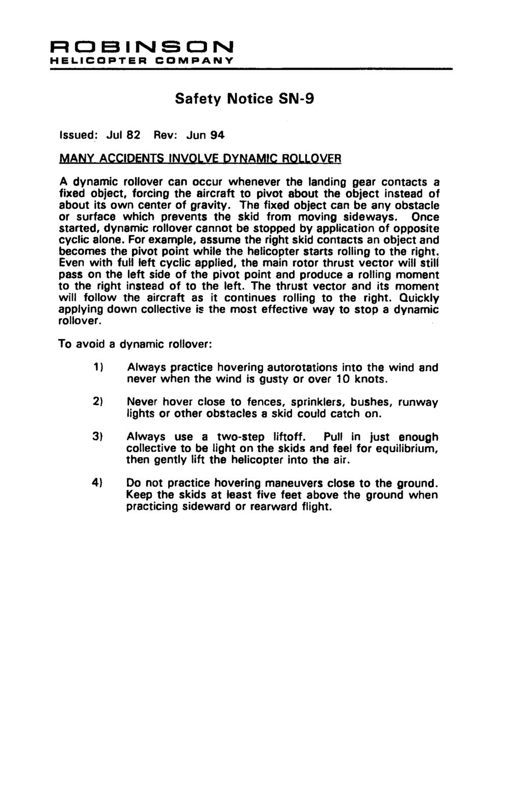
234
235
236
237
238
239
240
241 Safety Notice SN-22 Issued: July 1986 Revised: June 1994; October 2016 VORTEX RING STATE CATCHES MANY PILOTS BY SURPRISE A vertical or steep approach, particularly downwind, can cause the rotor to fly into its own downwash. This condition is known as vortex ring state due to the vortices that develop as the downwash is recirculated through the rotor disk. Once vortex ring state exists, adding power (raising collective) can unexpectedly increase descent rate due to the increase in downwash recirculating through the rotor. Maximum engine power may not be enough to stop the descent before a hard landing occurs. To avoid vortex ring state, reduce rate of descent before reducing airspeed. A good rule to follow is never allow your airspeed to be less than 30 knots until your rate-of-descent is less than 300 feet per minute. Signs that vortex ring state is developing include increased vibration levels, decreased control authority ( mushy controls ), and a rapid increase in sink rate. If vortex ring state is inadvertently encountered, two recovery techniques are available. One technique involves reducing collective pitch (to reduce downwash), lowering the nose to fly forward out of the downwash, and then applying recovery power. This can result in significant altitude loss which may not be acceptable on an approach. A second technique known as the Vuichard recovery involves applying recovery power while moving the helicopter sideways, assisted by tail rotor thrust, out of the downwash. When flown properly, the Vuichard recovery produces minimal altitude loss. Pilots should always be aware of wind conditions and plan descents to avoid vortex ring state. Training should emphasize recognition and avoidance of vortex ring state and include instruction in both recovery techniques.
242 Issued: Jul 86 Rev: Jun 94 Safety Notice SN-23 WALKING INTO TAIL ROTOR CAN BE FATAL Non-pilot passengers have been killed by inadvertently walking into a rotating tail rotor. Every possible precaution must be taken by the pilot to prevent this tragic type of accident. The following rules should always be observed: 1) Never allow anyone to approach the helicopter unless they are escorted or have been properly instructed. If necessary, shut down and stop rotors before boarding passengers. 2) Always have strobe light flashing when rotors are turning. 3) Instruct passengers to establish and maintain eye contact with pilot when approaching helicopter. (This will force them to approach only from the nose or side, never the tail). 4) Instruct passengers to leave the helicopter in full view of the pilot and walk only around the nose, never the tail. 5) Be especially careful when landing off airports as unseen children or adults might approach the helicopter from the rear.
243
244
245
246
247
248
SECTION 4 NORMAL PROCEDURES CONTENTS
 CONTENTS Page Recommended Airspeeds....................... 4-1 Daily or Preflight Checks........................ 4-1 Cold Weather Operation........................ 4-5 Before Starting Engine..........................
SECTION 3 EMERGENCY PROCEDURES CONTENTS
 CONTENTS Page Definitions.................................. 3-1 Power Failure - General......................... 3-1 Power Failure Above 500 feet AGL................ 3-2 Power Failure Between 8 and 500
SECTION 4 NORMAL PROCEDURES CONTENTS
 CONTENTS Page Recommended Airspeeds....................... 4-1 Daily or Preflight Checks........................ 4-1 Before Starting Engine.......................... 4-6 Engine Starting Tips...........................
SECTION 4 NORMAL PROCEDURES CONTENTS
 CONTENTS Page Recommended Airspeeds....................... 4-1 Daily or Preflight Checks........................ 4-1 Before Starting Engine.......................... 4-6 Starting Engine and Run-Up......................
SECTION 2 LIMITATIONS
 GENERAL This section includes operating limitations, instrument markings, and basic placards required for safe operation of the helicopter, its engine, and other standard systems. This helicopter is approved
SECTION 4 NORMAL PROCEDURES CONTENTS
 CONTENTS Page Recommended Airspeeds....................... 4-1 Daily or Preflight Checks........................ 4-1 Before Starting Engine.......................... 4-6 Starting Engine and Run-Up......................
R44 CADET PILOT S OPERATING HANDBOOK
 PILOT S OPERATING HANDBOOK AND FAA APPROVED ROTORCRAFT FLIGHT MANUAL RTR 463 THE IS FAA APPROVED IN NORMAL CATEGORY BASED ON 14 CFR PARTS 21 and 27. THIS HANDBOOK INCLUDES THE MATERIAL REQUIRED TO BE FURNISHED
Briefings & Checks. Robinson RH44 Raven II. Briefings & Checks Robinson RH44 Raven II. Helicopter Data (Meteo / NOTAM / DABS / W&B)
") Briefings & Checks Helicopter Data (Meteo / NOTAM / DABS / W&B) 1. Immatriculation: HB- 2. Empty weight: lbs 3. Main fuel: (USG x 6= lbs) lbs 5. Pilot / Pax / Baggage: lbs 6. actual TOM / HOGE: lbs / HOGE
Briefings & Checks Helicopter Data (Meteo / NOTAM / DABS / W&B) 1. Immatriculation: HB- 2. Empty weight: lbs 3. Main fuel: (USG x 6= lbs) lbs 5. Pilot / Pax / Baggage: lbs 6. actual TOM / HOGE: lbs / HOGE
CHAPTER 4 AIRWORTHINESS LIMITATIONS
 Section Title CHAPTER 4 AIRWORTHINESS LIMITATIONS 4-10 Airworthiness Limitations..................................... 4.1 4-20 Additional Limitations....................................... 4.3 4-21 Parts
R22 PILOT'S OPERATING HANDBOOK ROBINSON HELICOPTER CO. AND FAA APPROVED ROTORCRAFT FLIGHT MANUAL RTR 061 TORRANCE, CALIFORNIA
 R22 PILOT'S OPERATING HANDBOOK AND FAA APPROVED ROTORCRAFT FLIGHT MANUAL RTR 061 FAA APPROVED IN NORMAL CATEGORY BASED ON FAR 27 AND FAR 21. THIS HANDBOOK INCLUDES THE MATERIAL REQUIRED TO BE FURNISHED
Briefings and Checks Robinson R 44 Raven I
 Briefings and Checks Robinson R 44 Raven I Helicopter Data: 1. Call Sign... HB-ZOC 2. S/N... 1388 3. Empty weight... 1440 lbs 4. Fuel... 5. Weight PIC/PAX... 6. Actual TOM... 7. Actual HOGE... 8. MAX TOM...
Vso 61. Vs1 63. Vr 70. Vx 76. Vxse 78. Vy 89. Vyse. 89 (blue line) Vmc. 61 (radial redline) Vsse 76. Va 134) Vno 163
 Vmc. 61 (radial redline) Vsse 76. Va 134) Vno 163") PA34-200T Piper Seneca II Normal procedures V-speeds Knots Vso 6 Vs 63 Vr 70 Vx 76 Vxse 78 Vy 89 Vyse Vmc 89 (blue line) 6 (radial redline) Vsse 76 Va 2-36(@4507lbs 34) Vno 63 Vfe 38 (0*)/2(25*)/07(40*)
PA34-200T Piper Seneca II Normal procedures V-speeds Knots Vso 6 Vs 63 Vr 70 Vx 76 Vxse 78 Vy 89 Vyse Vmc 89 (blue line) 6 (radial redline) Vsse 76 Va 2-36(@4507lbs 34) Vno 63 Vfe 38 (0*)/2(25*)/07(40*)
CARENADO COPYRIGHTS. Normal & Emergency Checklist
 NORMAL PROCEDURES CHECKLIST PREFLIGHT CHECK Control wheel -- RELEASE BELTS Avionics -- OFF Master Switch -- ON Fuel quantity gauges -- CHECK Master switch -- OFF Ignition -- OFF Exterior -- CHECK FOR DAMAGE
R44H PILOT'S OPERATING HANDBOOK
 R44H PILOT'S OPERATING HANDBOOK AND FAA APPROVED ROTORCRAFT FLIGHT MANUAL RTR 462 THE R44n IS FAA APPROVED IN NORMAL CATEGORY BASED ON FAR 27 AND FAR 21. THIS HANDBOOK INCLUDES THE MATERIAL REQUIRED TO
CESSNA 182 CHECKLIST. LEFT WING Trailing Edge 1. Aileron CHECK freedom of movement and security
 CESSNA 182 CHECKLIST PRE-FLIGHT INSPECTION CABIN 1. Pilot s Operating Handbook AVAILABLE IN THE AIRPLANE (A.R.R.O.W.E) 2. Landing Gear Lever DOWN 3. Control Wheel Lock REMOVE 4. Ignition Switch OFF 5.
PA , Model E Normal Checklist (04/15/11)
") PA-23-250, Model E Normal Checklist (04/15/11) Key Airspeeds IAS-MPH V NE 249 V NO 198 V LO/LE 150 V A (At max gross weight.) 149 Speed for single engine cruise. 138 V FE Quarter Flaps 160 Half Flaps 140
PA-23-250, Model E Normal Checklist (04/15/11) Key Airspeeds IAS-MPH V NE 249 V NO 198 V LO/LE 150 V A (At max gross weight.) 149 Speed for single engine cruise. 138 V FE Quarter Flaps 160 Half Flaps 140
Interior Pre Flight Documents: Check Control Wheel Lock: Remove Flight Controls: Check Instruments: Check for Damage Switches: Verify All Off Master
 Interior Pre Flight Documents: Check Control Wheel Lock: Remove Flight Controls: Check Instruments: Check for Damage Switches: Verify All Off Master Switch ALT/BAT: On Fuel Gauge: Check Quantity Flaps:
Jump to Table of Contents
 Jump to Table of Contents PIPER AIRCRAFT CORPORATION PA-28R-201, CHEROKEE ARROW III SECTION 3 EMERGENCY PROCEDURES 3.3 EMERGENCY PROCEDURES CHECK LIST ENGINE FIRE DURING
Owners Manual. Table of Contents 4.1. INTRODUCTION SPEEDS FOR NORMAL OPERATION CHECKLIST & PROCEDURES 4
 NORMAL OPERATIONS Table of Contents 4.1. INTRODUCTION 2 4.2. SPEEDS FOR NORMAL OPERATION 2 4.3. CHECKLIST & PROCEDURES 4 4.3.1. PREFLIGHT INSPECTION 4 4.3.2. BEFORE STARTING ENGINE 8 4.3.3. STARTING ENGINE
SECTION IV NORMAL PROCEDURES TABLE OF CONTENTS
 SECTION IV NORMAL PROCEDURES TABLE OF CONTENTS SUBJECT PAGE Speeds for Safe Operation 4-3 Preflight Inspection 4-4 Before Starting 4-5 External Power 4-6 Starting Engine Using Auxiliary Power Unit. 4-7
Document No. ST-931-RFM-0001
 275 Palos Verdes Dr. North Document No. ST-931-RFM-1 FAA APPROVED Rotorcraft Flight Manual Supplement to the Robinson R44 Pilot s Operating Handbook and FAA Approved Rotorcraft Flight Manual HeliSAS Aircraft
Preflight Inspection Cabin EMPENNAGE RIGHT WING Trailing Edge RIGHT WING NOSE
 Preflight Inspection Cabin 1. Control Wheel Lock REMOVED 2. Ignition Switch OFF 3. Avionics Power Switch OFF 4. Master Switch ON 5. Fuel Quantity Indicators CHECK QUANTITY 6. Master Switch OFF 7. Fuel
SECTION 9 SUPPLEMENTS
 ROBINSON MODEL R44 II SECTION 9 SUPPLEMENTS SECTION 9 SUPPLEMENTS OPTIONAL EQUIPMENT SUPPLEMENTS Information contained in the following supplements applies only when the related equipment is installed.
Owners Manual. Table of Contents 3.1. INTRODUCTION AIRSPEEDS FOR EMERGENCY OPERATION OPERATIONAL CHECKLISTS 3
 EMERGENCY PROCEDURES Table of Contents 3.1. INTRODUCTION 2 3.2. AIRSPEEDS FOR EMERGENCY OPERATION 2 3.3. OPERATIONAL CHECKLISTS 3 3.3.1. ENGINE FAILURES 3. ENGINE FAILURE DURING TAKEOFF RUN 3. ENGINE FAILURE
EMERGENCY PROCEDURES SECTION I. HELICOPTER SYSTEMS
 9-1. HELICOPTER SYSTEMS. EMERGENCY PROCEDURES SECTION I. HELICOPTER SYSTEMS This section describes the helicopter systems emergencies that may reasonably be expected to occur and presents the procedures
CHAPTER 13 INSTRUMENTS
 CHAPTER 13 INSTRUMENTS Section Title Page 13.000 Description.............................................. 13.1 13.100 Pitot-Static System......................................... 13.3 13.200 Primary Instruments........................................
Piper Archer II (PA )
") 1. Oil... 6-8 qts, Cap Secure CABIN 1. POH & Documents.. Check Available 2. Magneto Switch...... OFF 3. Pitot/Static Drains... Push to Drain 4. Avionics/Electrical Switches... OFF 5. Master Switch. ON
1. Oil... 6-8 qts, Cap Secure CABIN 1. POH & Documents.. Check Available 2. Magneto Switch...... OFF 3. Pitot/Static Drains... Push to Drain 4. Avionics/Electrical Switches... OFF 5. Master Switch. ON
N123AX Piper Saratoga II HP (PA-32R-301) Checklist (v23 - Revision 3 April 2011) AIRSPEEDS FOR SAFE OPERATIONS. Best Rate of Climb (gear up, flaps up)
 Checklist (v23 - Revision 3 April 2011) AIRSPEEDS FOR SAFE OPERATIONS. Best Rate of Climb (gear up, flaps up)") N123AX Piper Saratoga II HP (PA-32R-301) Checklist (v23 - Revision 3 April 2011) AIRSPEEDS FOR SAFE OPERATIS Best Rate of Climb (gear down, flaps up) Best Rate of Climb (gear up, flaps up) Turbulent Air
N123AX Piper Saratoga II HP (PA-32R-301) Checklist (v23 - Revision 3 April 2011) AIRSPEEDS FOR SAFE OPERATIS Best Rate of Climb (gear down, flaps up) Best Rate of Climb (gear up, flaps up) Turbulent Air
OUTLINE. Commercial Requirements Insurance Mins Basic Info Systems Limitations Performance Charts Questions
 T-34B GROUND SCHOOL OUTLINE Commercial Requirements Insurance Mins Basic Info Systems Limitations Performance Charts Questions COMMERCIAL REQUIREMENTS 61.129 Aeronautical experience. (a) For an airplane
Cessna 172 Skyhawk. Aircraft Checklist Models: R & S
 Cessna 172 Skyhawk Aircraft Checklist Models: R & S This is an abbreviated checklist. Most explanatory items, notes cautions and warnings have been omitted for brevity. Procedures in red/bold text in this
AIRSPEEDS. Cessna 172R Emergency Checklist
 AIRSPEEDS AIRSPEEDS FOR EMERGENCY OPERATION Cessna 172R Emergency Checklist INTRODUCTION This document provides checklist and amplified procedures for coping with emergencies that may occur. Emergencies
NORMAL CHECKLIST ATTENTION!
 Avion Training CHECKLIST Normal Checklist CESSNA 172R / TC-STS Cessna 172 R TC-STS NORMAL CHECKLIST ATTENTION! DO NOT STOW THIS CHECKLIST IN DIRECT SUNLIGHT Avion Training - Doc.nr. 212 Revision 1 / 02022018
PA-28R 201 Piper Arrow
 Beale Aero Club Aircraft Written Test PA-28R 201 Piper Arrow (Required passing score: 80%) 1. If an engine power loss occurs immediately after take off, the pilot s reaction should be to: a. maintain safe
a. Lycoming IO-520J 250 HP c. Lycoming O-540-J3C5D 235 HP b. Continental O450T 330 HP d. Lycoming O-360A 180 HP
 Three points each question Page 1 of 6 References: Pilot's Operating Handbook for the 1979 Cessna R182 Model; Flying Magazine Article "Cessna 182 Safety Report;" RAFA SOP; and Refueling Instructions found
INDEX. Preflight Inspection Pages 2-4. Start Up.. Page 5. Take Off. Page 6. Approach to Landing. Pages 7-8. Emergency Procedures..
 INDEX Preflight Inspection Pages 2-4 Start Up.. Page 5 Take Off. Page 6 Approach to Landing. Pages 7-8 Emergency Procedures.. Page 9 Engine Failure Pages 10-13 Propeller Governor Failure Page 14 Fire.
INDEX: Normal Procedures Emergency Procedures Pre Flight Inspection NORMAL PROCEDURES BEFORE STARTING ENGINE
 INDEX: Normal Procedures Emergency Procedures Pre Flight Inspection NORMAL PROCEDURES BEFORE STARTING ENGINE 1. Preflight Inspection -- COMPLETE 2. Seats, Belts, Shoulder Harnesses -- ADJUST and LOCK 3.
SECTION 7 SYSTEMS DESCRIPTION CONTENTS
 CONTENTS Page General..................................... 7-1 Rotor Systems................................ 7-2 Drive System................................. 7-2 Powerplant..................................
Cessna 172P PPL Checklist Page 1
 Cessna 172P PPL Checklist 06-08-2017 Page 1 Cessna 172P PPL Checklist 06-08-2017 Page 2 Checklist Items Informational Items Critical Memory Items PREFLIGHT COCKPIT CHECK (DO-LIST) Pitot Cover -- REMOVE
CHAPTER 3 LIFE-LIMITED COMPONENTS
 Section Title CHAPTER 3 LIFE-LIMITED COMPONENTS 3.000 Life-Limited Components...................................... 3.1 3.001 Introduction............................................. 3.1 3.002 Time-In-Service
PA32-RT LANCE II CHECKLIST
 PA32-RT LANCE II CHECKLIST 6815.10.1112 1 Normal Procedures PREFLIGHT CHECK Control Wheel... RELEASE BELTS Parking brake... Set Master Switch... ON Fuel Quantity Gauges... check Master Switch... OFF Ignition...
TECNAM P2004 BRAVO N128LS
 TECNAM P2004 BRAVO N128LS GENERAL INFORMATION NORMAL PROCEDURES TIME SENSITIVE EMERGENCY TECNAM P2004 BRAVO CHECKLIST [FLIGHT PLAN DESIGNATION IS BRAV ] EMERGENCY CONTACT The following are First Landings'
CHAPTER 3 LIFE-LIMITED COMPONENTS
 CHAPTER 3 LIFE-LIMITED COMPONENTS Section Title 3.100 Life-Limited Components..................................... 3.1 3.110 Time-in-Service Records................................... 3.1 3.120 Fatigue
Cessna 182S-CHECKLIST PROCEDURES
 Cessna 182S-CHECKLIST PROCEDURES PREFLIGHT INSPECTION 1 CABIN 1. Pitot Tube Cover -- REMOVE (if installed) and check for stoppage 2. Pilot s Operating Handbook AVAILABLE IN THE AIRPLANE 3. Airplane Weight
CHAPTER 17 LIMITATIONS TABLE OF CONTENTS
 CHAPTER 17 LIMITATIONS TABLE OF CONTENTS INTRODUCTION... 5 GENERAL... 5 Flight Crew... 6 Configuration... 6 Optional Equipment... 6 Doors Opened / Removed... 6 Passenger Seats... 6 Cargo... 7 Weight and
AIRPLANE FLIGHT MANUAL
 Thrush Aircraft Inc Model S2R-T34 MANUAL ORGANIZATION SECTION I -----------------------------------------------------LIMITATIONS SECTION II -------------------------------------- NORMAL PROCEDURES SECTION
N1523J CHECKLIST PA Nebraska Flight Center Eppley Airfield 3737 Orville Plaza Omaha, NE Tel. (402)
") CHECKLIST N1523J 1967 Cherokee 140 PA-28-140 F Nebraska Flight Center Eppley Airfield 3737 Orville Plaza Omaha, NE 68110 Tel. (402) 342-4314 www.nebflight.com Piper Cherokee 140 N1523J 1967 GENERAL INFORMATION
CHECKLIST N1523J 1967 Cherokee 140 PA-28-140 F Nebraska Flight Center Eppley Airfield 3737 Orville Plaza Omaha, NE 68110 Tel. (402) 342-4314 www.nebflight.com Piper Cherokee 140 N1523J 1967 GENERAL INFORMATION
Van s Aircraft RV-7A. Pilot s Operating Handbook N585RV
 Van s Aircraft RV-7A Pilot s Operating Handbook N585RV PERFORMANCE SPECIFICATIONS SPAN:..25 0 LENGTH...20 4 HEIGHT:.. 7 10 SPEED: Maximum at Sea Level...180 knots Cruise, 75% Power at 8,000 Ft...170 knots
TECNAM P92 EAGLET N615TA TECNAM P92 EAGLET CHECKLIST [FLIGHT PLAN DESIGNATION IS ECHO ]
![TECNAM P92 EAGLET N615TA TECNAM P92 EAGLET CHECKLIST [FLIGHT PLAN DESIGNATION IS ECHO ]](/thumbs/86/93080937.jpg "TECNAM P92 EAGLET N615TA TECNAM P92 EAGLET CHECKLIST [FLIGHT PLAN DESIGNATION IS ECHO ]") TECNAM P92 EAGLET CHECKLIST [FLIGHT PLAN DESIGNATION IS ECHO ] EMERGENCY CONTACT The following are First Landings' emergency contact telephone numbers. We ask that you call the numbers in the order listed.
TECNAM P92 EAGLET CHECKLIST [FLIGHT PLAN DESIGNATION IS ECHO ] EMERGENCY CONTACT The following are First Landings' emergency contact telephone numbers. We ask that you call the numbers in the order listed.
FLASHCARDS AIRCRAFT. Courtesy of the Air Safety Institute, a Division of the AOPA Foundation, and made possible by AOPA Services Corporation.
 AIRCRAFT FLASHCARDS Courtesy of the Air Safety Institute, a Division of the AOPA Foundation, and made possible by AOPA Services Corporation. Knowing your aircraft well is essential to safe flying. These
COLUMBIA 350 EMERGENCY PROCEDURES
 COLUMBIA 350 EMERGENCY PROCEDURES TABLE OF CONTENTS EMERGENCY PROCEDURES LANDING AND TAKEOFF Engine Failure During Takeoff...1 Engine Failure Immediately After Takeoff...1 Engine Failure During Climb to
Robinson R22 Pilot s Technical Quiz
 Robinson R22 Pilot s Technical Quiz Version 1.0a 2002-10-21 Candidate Examiner Name Licence class Licence number Name Licence number Capacity Centre Date Mark (Pass is 80/100= 80%) Instructions: This is
CHECKLIST 1969 CESSNA 172-K. NOTE: Verify all information with airplane's POH
 CHECKLIST 1969 CESSNA 172-K NOTE: Verify all information with airplane's POH PRE-FLIGHT INSPECTION 1 CABIN 1 A.R.R.O.W. CHECK Airworthiness Cert. In Clear View Registration In Clear View Radio License
DEPARTMENT OF TRANSPORTATION FEDERAL AVIATION ADMINISTRATION TYPE CERTIFICATE DATA SHEET NO. A13CE
 DEPARTMENT OF TRANSPORTATION FEDERAL AVIATION ADMINISTRATION A13CE Revision 28 CESSNA 177 177A 177B November 16, 2010 TYPE CERTIFICATE DATA SHEET NO. A13CE WARNING: Use of alcohol-based fuels can cause
Accident Prevention Program
 Accident Prevention Program Maintenance Aspects of Owning Your Own Airplane Introduction As an owner-pilot, FAR Part 43 allows you to perform certain types of inspections and maintenance on your airplane.
Aircraft Checklist Cessna 182T
 Aircraft Checklist Cessna 182T This is an abbreviated checklist. Most explanatory items, notes cautions and warnings have been omitted for brevity. Procedures in red/bold in this checklist should be committed
PREFLIGHT CHECK COCKPIT RIGHT WING. NORMAL PROCEDURRES CHECKLIST PA-28RT 201 Arrow IV
 NORMAL PROCEDURRES CHECKLIST PA-28RT 201 Arrow IV PREFLIGHT CHECK COCKPIT Control Wheel -- Release Restraints Avionics -- OFF Parking Brake -- SET All Switches -- OFF Mixture -- IDLE CUT-OFF Master Switch
PA GURW (December 30, 2000) PRE-START. Langley Flying School. Airspeeds (MPH) for Safe Operation. Cockpit Checks
 PRE-START. Langley Flying School. Airspeeds (MPH) for Safe Operation. Cockpit Checks") Langley Flying School PA-34-200 GURW (December 30, 2000) Airspeeds (MPH) for Safe Operation V y (all weights) 105 V x (all weights) 90 En Route Climb 120 V mc 80 V yse 105 V xse 93 V r 80 V r (25 Flaps)
Langley Flying School PA-34-200 GURW (December 30, 2000) Airspeeds (MPH) for Safe Operation V y (all weights) 105 V x (all weights) 90 En Route Climb 120 V mc 80 V yse 105 V xse 93 V r 80 V r (25 Flaps)
CHAPTER 13 INSTRUMENT SYSTEM
 CHAPTER 13 INSTRUMENT SYSTEM Section Title 13-00 Description............................................... 13.1 13-10 Pitot-Static System......................................... 13.3 13-20 Primary Instruments.........................................
DO NOT WRITE ON THIS TEST FEB 2013 Elmendorf Aero Club Aircraft Test. Cessna - 182
 DO NOT WRITE ON THIS TEST FEB 2013 Elmendorf Aero Club Aircraft Test Cessna - 182 For the following questions, you will need to refer to the Pilots Information Manual for the C-182R. The bonus questions
Aircraft Checklist Commander 114
 Aircraft Checklist Commander 114 This is an abbreviated checklist. Most explanatory items, notes cautions and warnings have been omitted for brevity. Procedures in red/bold text in this checklist should
Elmendorf Aero Club Aircraft Test
 DO NOT WRITE ON THIS TEST FEB 2013 Elmendorf Aero Club Aircraft Test Cessna - 182 For the following questions, you will need to refer to the Pilots Information Manual for the C-182R. The bonus questions
Elmendorf Aero Club Aircraft Test
 DO NOT WRITE ON THIS TEST JAN 2014 Elmendorf Aero Club Aircraft Test SENECA II For the following questions, you will need to refer to the Pilots Information Manual for the PA-34-200T. USE ANSWER SHEET
V - Speeds. RV-10 V fe Flaps Speeds Trail (0 deg) Half (15 deg) Full (30 deg) 122 kias 96 kias. 80 kias
 Half (15 deg) Full (30 deg) 122 kias 96 kias. 80 kias") RV-10 Check List V - Speeds RV-10 V fe Flaps Speeds Trail (0 deg) Half (15 deg) Full (30 deg) 122 kias 96 kias 87 kias V s1 Stall (Flap Up) 60 kias V s0 Stall (Flap 40 deg) 55 kias Best Glide 80 kias V
RV-10 Check List V - Speeds RV-10 V fe Flaps Speeds Trail (0 deg) Half (15 deg) Full (30 deg) 122 kias 96 kias 87 kias V s1 Stall (Flap Up) 60 kias V s0 Stall (Flap 40 deg) 55 kias Best Glide 80 kias V
Cessna 172RG WARNING. Maximum Demonstrated Crosswind. Takeoff or landing..15 KTS
 Cessna 172RG INTRODUCTION: This aircraft checklist contains information from the original manufacturer s Pilot Information Manual. Normal procedures associated with optional systems can be found in Section
ADVANCED TECHNOLOGY. Automatic Clutch Engagement. Simplifies startup procedure and reduces the possibility of an overspeed.
 ADVANCED TECHNOLOGY Advanced Warning Devices. The instrument panel includes low fuel warning light, main gearbox temperature and chip lights, tail gearbox chip light, low oil pressure light, engine fire
JODEL D.112 INFORMATION MANUAL C-FVOF
 JODEL D.112 INFORMATION MANUAL C-FVOF Table of Contents I General Description...4 Dimensions:...4 Powertrain:...4 Landing gear:...4 Control travel:...4 II Limitations...5 Speed limits:...5 Airpeed indicator
UNCONTROLLED COPY WHEN DOWNLOADED OR PRINTED ENSTROM 280FX OPERATOR S MANUAL. Record of Revisions. Date Inserted
 ENSTROM 280FX OPERATOR S MANUAL Record of Revisions Revision Number Issue Date Date Inserted By 1 12/31/80 2/21/12 J. Wingers 2 1/11/85 2/21/12 J. Wingers 3 7/12/85 2/21/12 J. Wingers 4 1/11/91 2/21/12
M20J-201 Checklist BEFORE STARTING ENGINE
 M20J-201 Checklist BEFORE STARTING ENGINE Preflight... COMPLETE Baggage door... LATCHED/LOCKED Door... LATCHED/LOCKED Seatbelts... FASTENED Passenger brief....... [seatbelts/exits/smoking/talking/traffic]
PA ARCHER II Quick Reference Handbook
 PA28-180 ARCHER II Quick Reference Handbook ALL GREY SHADED AREAS ARE MEMORY ITEMS 7813.03.0116 1 Table of Contents Normal Procedures... 4 PREFLIGHT CHECK... 4 BEFORE START... 6 FLOODED ENGINE START...
SECTION 2 LIMITATIONS
 SECTION 2 TABLE OF CONTENTS PARAGRAPH PAGE 2.1 INTRODUCTION 2-1 2.2 KINDS OF OPERATIONS LIMITS 2-1 2.3 AIRSPEED 2-3 2.4 AIRSPEED INDICATOR MARKINGS 2-3 2.5 POWER PLANT 2-4 2.6 POWER PLANT INSTRUMENT MARKINGS
CHAPTER 12 SERVICING. Section Title Page
 CHAPTER 12 SERVICING Section Title Page 12-10 Main Rotor Gearbox.................................. 12.1 12-11 Servicing................................. 12.1 12-12 Filter Replacement...........................
SECTION 9 SUPPLEMENTS
 SUPPLEMENTS SUPPLEMENTS OPTIONAL EQUIPMENT SUPPLEMENTS Information contained in the following supplements applies only when the related equipment is installed. CONTENTS Page Heated Pitot.......................
LANCAIR LEGACY PRE-TEST FLIGHT INSPECTION (8-04)
") LANCAIR LEGACY PRE-TEST FLIGHT INSPECTION (8-04) OWNER PHONE # ADDRESS N SERIAL # AIRCRAFT TYPE DATE / / TACH TIME hrs. TOTAL TIME hrs. EMPTY WEIGHT CG. PAINT & INTERIOR? YES NO ENGINE TYPE PROPELLER ALL
LANCAIR LEGACY PRE-TEST FLIGHT INSPECTION (8-04) OWNER PHONE # ADDRESS N SERIAL # AIRCRAFT TYPE DATE / / TACH TIME hrs. TOTAL TIME hrs. EMPTY WEIGHT CG. PAINT & INTERIOR? YES NO ENGINE TYPE PROPELLER ALL
I. DISPATCH PLANNING & AIRCRAFT EXTERIOR CHECK
 SCHODACK AVIATION Page 1 of 10 I. DISPATCH PLANNING & AIRCRAFT EXTERIOR CHECK 1. Flight Planning 1. Aircraft requirements & preparation: Required aircraft documents: Airworthiness Certificate Registration
PA28R ARROW CHECKLIST
 PA28R ARROW CHECKLIST 2300.11.0112 1 Normal Procedures Initial PREFLIGHT CHECK General Appearance... CHECKED Position & Taxi Path... CHECKED Tie Downs, Locks, Chocks & Covers... REMOVED Cockpit Controls...UNLOCKED
CESSNA SECTION 4. Unless otherwise noted, the following speeds are based on a maximum weight of 2550 pounds and may be used for any lesser weight.
 CESSNA SECTION 4 INTRODUCTION Section 4 provides procedures and amplified instructions for normal operations using standard equipment. Normal procedures associated with optional systems can be found in
CHAPTER 18 WEIGHT AND BALANCE
 CHAPTER 18 WEIGHT AND BALANCE Section Title 18-10 Leveling................................................. 18.1 18-11 Leveling at Lower Right Side Frame Tube & Aft Landing Gear Cross Tube.. 18.1 18-12
CESSNA 172I CESSNA 172I PREFLIGHT INSPECTION
 PREFLIGHT INSPECTION Visually check airplane for general condition during walk-around inspection. In cold weather, remove even small accumulations of frost, ice or snow from wing, tail and control surfaces.
I. DISPATCH PLANNING & AIRCRAFT EXTERIOR CHECK
 SCHODACK AVIATION Page 1 of 10 I. DISPATCH PLANNING & AIRCRAFT EXTERIOR CHECK 1. Flight Planning 1. Aircraft requirements & preparation: 1. Required aircraft documents: 1. Airworthiness Certificate 2.
CESSNA 172N 08E/97E CESSNA 172N 08E/97E PREFLIGHT INSPECTION
 PREFLIGHT INSPECTION Visually check airplane for general condition during walk-around inspection. In cold weather, remove even small accumulations of frost, ice or snow from wing, tail and control surfaces.
QUICK REFERENCE HANDBOOK TECNAM P92 ECHO
 NORMAL LISTS PRE-START S Park brake Left fuel cock Flight Instruments (No broken glass or bent needles) Engine Instruments (No broken glass or bent needles) Right fuel cock Fuses Landing Light Avionics
SECTION 10 SAFETY TIPS AND NOTICES. CONTENTS Page General Safety Tips Pilot Knowledge and Proficiency
 ROBINSON MODEL R44 II SECTION 10 SAFETY TIPS SECTION 10 SAFETY TIPS AND NOTICES CONTENTS Page General.................................. 10-1 Safety Tips............................... 10-1 Pilot Knowledge
The engines are designed to use 100/130 octane fuel. If not available use next higher grade. - 1
 PNEUMATIC SYSTEM The aircraft has a dual pneumatic system. In case of failure of either pneumatic pump, the system will automatically select the operative source. (Inoperative source will be indicated
Elmendorf Aero Club Aircraft Test
 DO NOT WRITE ON THIS TEST FEB 2013 Elmendorf Aero Club Aircraft Test Cessna - 172 For the following questions, you will need to refer to the Pilots Information Manual for the C-172R (180hp). The bonus
T-6B EMERGENCY PROCEDURE CRITICAL ACTION MEMORY ITEMS & OPERATING LIMITATIONS EMERGENCY PROCEDURE CRITICAL ACTION MEMORY ITEMS
 T-6B EMERGENCY PROCEDURE CRITICAL ACTION MEMORY ITEMS & OPERATING LIMITATIONS EMERGENCY PROCEDURE CRITICAL ACTION MEMORY ITEMS ABORT START PROCEDURE or STARTER switch AUTO/RESET EMERGENCY ENGINE SHUTDOWN
Elmendorf Aero Club Aircraft Test
 DO NOT WRITE ON THIS TEST FEB 2014 Elmendorf Aero Club Aircraft Test Cessna - 185 For the following questions, you will need to refer to the Pilots Information Manual for the C-185F and Graphic Engine
AIRPLANE FLIGHT MANUAL
 Thrush Aircraft Inc Model S2R-R1340 MANUAL ORGANIZATION SECTION I -----------------------------------------------------LIMITATIONS SECTION II -------------------------------------- NORMAL PROCEDURES SECTION
NORMAL PROCEDURRES CHECKLIST PA T SENECA II PREFLIGHT CHECK INSIDE CABIN OUTSIDE CABIN
 NORMAL PROCEDURRES CHECKLIST PA-34-200T SENECA II PREFLIGHT CHECK INSIDE CABIN Avionics Master Switch -- OFF Landing Gear Control. -- DOWN Mixture Controls -- IDLE/CUTOFF Ignition Switches -- OFF Master
CHAPTER 22 AUTOPILOT
 Section Title CHAPTER 22 AUTOPILOT 22-00 Description............................................... 22.1 22-10 (Pitch) Servo Assembly...................................... 22.3 22-20 (Roll) Servo Assembly.......................................
Gyroplane questions from Rotorcraft Commercial Bank (From Rotorcraft questions that obviously are either gyroplane or not helicopter)
") Page-1 Gyroplane questions from Rotorcraft Commercial Bank (From Rotorcraft questions that obviously are either gyroplane or not helicopter) "X" in front of the answer indicates the likely correct answer.
Page-1 Gyroplane questions from Rotorcraft Commercial Bank (From Rotorcraft questions that obviously are either gyroplane or not helicopter) "X" in front of the answer indicates the likely correct answer.
FLIGHT HANDLING NOTES CHECK LIST & PERFORMANCE DATA GROB G 109B G-KNEK
 FLIGHT HANDLING NOTES CHECK LIST & PERFORMANCE DATA GROB G 109B G-KNEK Before Starting Engine PREFLIGHT CHECK COMPLETED. 1. Adjust pedals and back rests 2. Adjust and secure seat harness 3. Folding doors
Pilot s Checklist PIPER ARROW PA-28R-201
 Pilot s Checklist PIPER ARROW PA-28R-201 Original Issue 10/31/2012 REVISIONS Changes and/or additions in this checklist will be covered by Owner Advisories published by the Piper Aircraft Corporation.
Registration Number. Serial Number
 Registration Number Serial Number This supplement must be attached to the DMCR Approved Airplane Flight Manual dated October 1, 1954 or later approved revision and must be carried in the airplane when
R44 RAVEN CLIPPER SPECIFICATIONS DIMENSIONS ROBINSON HELICOPTER COMPANY
 SPECIFICATIONS Engine Horsepower RAVEN I Lycoming O-540, six cylinder, carbureted Derated to 225 for takeoff and 205 continuous RAVEN II Lycoming IO-540, six cylinder, fuel injected Derated to 245 for
Registration Number. Serial Number
 Registration Number Serial Number This supplement must be attached to the DMCR Approved Airplane Flight Manual listed on page 2 of this supplement or later approved revision and must be carried in the
King Air B90. Speeds (KIAS)
") King Air B90 Speeds (KIAS) V MCA 92 V SSE (101) Derived from C90 V X 101 V Y 114 Down to 103 @ 30 000 V XSE 101 V YSE 110 Down to 101 @ 24 000 V A 169 V R 92 V 1 101 V MO 208 V FE 174 35% 130 100% V LE
King Air B90 Speeds (KIAS) V MCA 92 V SSE (101) Derived from C90 V X 101 V Y 114 Down to 103 @ 30 000 V XSE 101 V YSE 110 Down to 101 @ 24 000 V A 169 V R 92 V 1 101 V MO 208 V FE 174 35% 130 100% V LE
4A.2 AIRSPEEDS FOR NORMAL OPERATING PROCEDURES
 Normal Operating DA 40 AFM 4A.1 INTRODUCTION Chapter 4A contains checklists and describes extended procedures for the normal operation of the airplane. 4A.2 AIRSPEEDS FOR NORMAL OPERATING PROCEDURES Flight
CHAPTER 22 SERVICING
 CHAPTER 22 SERVICING Section Title 22-10 Main Rotor Gearbox......................................... 22.1 22-11 Cleaning Chip Detector..................................... 22.3 22-12 Cleaning Sight Gage.......................................