Rex Healthcare Medium Voltage System Presentation APEC 2015 March 15-19, 2015
|
|
|
- Susanna Ramsey
- 5 years ago
- Views:
Transcription
1 Rex Healthcare Medium Voltage System Presentation APEC 2015 March 15-19, 2015 Maximizing the Efficiency of Hospital Distribution Systems Through the Use of Advancing Technology and Design Creativity MISSION: To demonstrate the critical design requirements that maximize the functionality of a large healthcare facility s electrical support system while ensuring the safety and welfare of patients, doctors and staff, operators, maintenance personnel, and visitors; and, to provide a backup and redundant system that provides manual and automatic alternate paths of service that minimize inconvenience to the hospital s function and operation due to regular or routine maintenance, internal equipment failures, or utility outages. The design objective was to meet the above criteria by providing a new 5 Kv electrical system that met the existing hospital functions and features while increasing reliability and redundancy, and, by utilizing modern state of the art equipment and computer based programmable controls and monitoring. Large hospitals have necessitated the need for designers to use medium voltage systems along with large generators for distribution of the utility and emergency sources. The following is a case study of the new medium voltage system addition at the Rex Healthcare facility in Raleigh, NC

2 Rex Healthcare Rex Healthcare is a 600 bed hospital providing care for patients in Raleigh, North Carolina, Wake County, and the surrounding area. The hospital was constructed in and opened at its present location in In addition to its inpatient capability, it consists of 33 state of the art operating rooms, up-to-date Same Day Surgery Facilities, a fully equipped Emergency Department, a hi-tech Cancer Center, a vibrant Birthing Center, and efficient administrative facilities.

3 Future Heart and Vascular Facility In addition the hospital presently has under construction a 300,000 square foot Heart and Vascular Hospital onsite. This addition is expected to come on line in Future additions both on and offsite will be developed as needed or required.


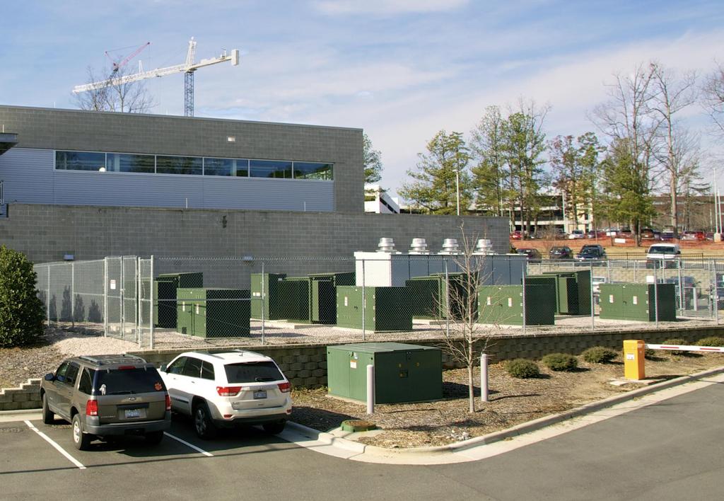
4 Central Energy Plant Facility
5 Construction of a $25 million onsite Central Energy Plant (CEP) began in 2011 and came on line in mid The facility includes an outdoor 5 Kw service switchgear lineup, a large indoor functional emergency generator room, three indoor 5 Kv switchgear rooms, a master control room, and a modern boiler room. A chiller addition is planned for the CEP as hospital cooling loads increase. The recently completed electrical system addition at the CEP consists of a top-of-the-line automated distribution switching system supported by a computer PLC based programmed Supervisory Control and Data Acquisition system (SCADA). The CEP system distributes both the hospital s utility provided voltage source and its onsite emergency generator source via separate paths throughout the hospital 5 Kv distribution system. The SCADA system controls, monitors, indicates, and stores operating data including voltage, current, kilowatts, and frequency. Other load parameters at each feeder and distribution circuit breaker are displayed, as well as totalizing the system loads at the main panel. Operating parameters as well as historical records are stored which maintain printable data as required by healthcare authorities.
6 Out of tolerance conditions alert the control system to automatically isolate the source or failed condition, seek an available alternate path, and, when available, transfer the load to a safe and reliable alternate path. In the case of a total failure of the utility source, the system automatically initiates the generator powered emergency system, disconnects from the utility system, and transfers the emergency source to an alternate distribution system. The system also automatically sheds or adds loads based on the source capacity available.

7 CEP facility layout Generator room The generator room houses two 5 Kv 3.0 Mw generators powered by 4423 HP diesel engines and one 2.25 Mw unit powered by a 3100 HP diesel engine.

8 Control Room The control room consists of a main control panel screen with the system 5 Kv one line diagram, multiple monitoring screens for engines, generators, switchgear, and data. The control panel also displays operating screens for controlling the system in either an automatic or manual mode.
9 Four Separated Switchgear Lineups Outdoor utility service Indoor generator paralleling Indoor utility fed Indoor emergency fed
10 Along with the adjacent outdoor utility fed outdoor 5 Kv switchgear lineup, the CEP houses three separated 5 Kv switchgear rooms. The utility fed outdoor switchgear lineup provides two circuit breaker feeds to the indoor utility switchgear which provides utility voltage to the CEP indoor switchgear. The outdoor switchgear is sized for future utility transformer upgrades. The utility fed indoor switchgear then provides a circuit breaker which feeds the utility source to the hospital service building (SB) switchgear. Both of these lineups at the CEP and service building will also feed future campus loads with the utility source. The indoor generator fed paralleling switchgear lineup allows circuit breakers to close to this bus when the generators parallel with each other, and, then close two outgoing circuit breakers which provide the generator voltage source to the indoor emergency distribution switchgear. This switchgear is sized for future generator upgrades. The indoor emergency switchgear lineup fed by the paralleled generator source then feeds the paralleled emergency source to the hospital s service building switchgear. Both of these lineups at the CEP and service building will also feed future campus loads with the emergency source. Two circuit breakers in each of the two indoor distribution switchgear lineups at the CEP maintain the utility source on both the utility fed switchgear bus as well as on the emergency switchgear bus when the system is not on the generator source. These circuit breakers also allow the generator source to parallel with the utility source. The CEP design allows the addition of a future chiller facility which will house up to eight (8) 1600 ton chillers fed from the CEP utility and emergency switchgear.
11 Trends In Standby Power Systems for Healthcare Facilities by Timothy Coyle, PE, Engineering Systems, July 2014 (Quote) Larger healthcare facilities require more standby power due to size and the impracticality of evacuating a large patient census during an extended utility outage. Sufficient capacity is required to permit normal or near normal operations of the facility. Higher power demands lead to the use of larger generators at higher voltages to allow practical and economical distribution of power throughout the facility. (End quote) The concept connects the utility and the emergency sources for paralleling, and, it can maintain voltage on the emergency distribution system when the generator source is not on line.
12 5 Kv Electrical Distribution

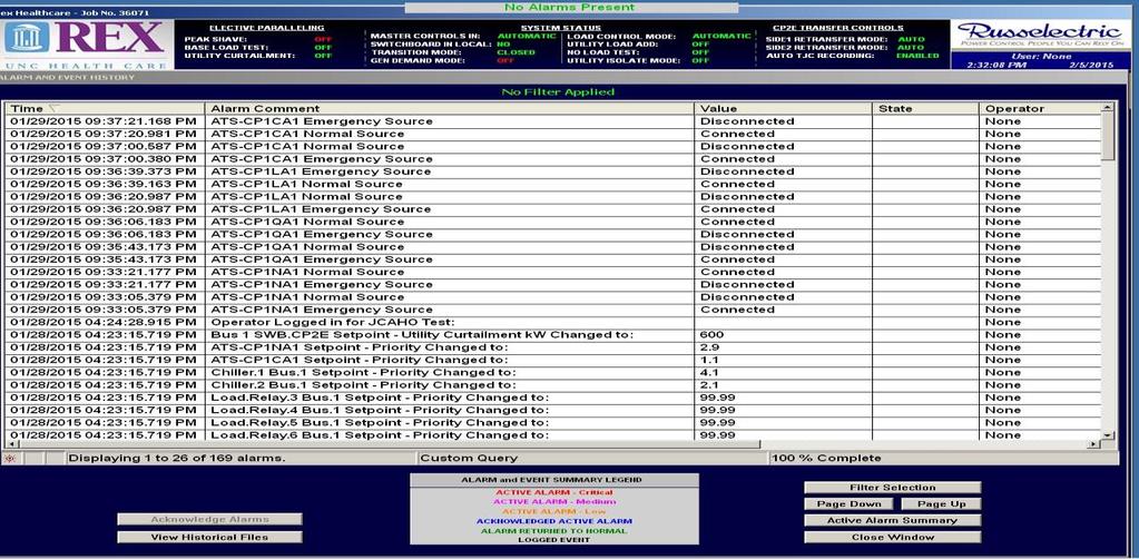
13 SCADA Control and Data
14 Load Data The hospital s total connected load is approximately 20,000 Kw. The hospital s present peak load is approximately 5,200 Kw. Approximately 3600 Kw is on the hospital preferred emergency bus. Approximately 1600 Kw is on the hospital nonpreferred or normal bus. Future 5 year peak demand load is projected to be approximately 7,500 8,000 kw

15 Onsite Utility Owned 25 Kv Primary Source Equipment
16 Separate 25 Kv Utility Sources Two utility owned 25 Kv feeders from separate offsite substations each feed an onsite pad mounted distribution dead front switchgear unit. Two 4-bay enclosed pad mounted 25 Kv switchgear units with two switch bays and two fuse bays each (total 4 switches, 4 fuse)
17 There are three normally closed (NC) switches in the two units, one for the incoming preferred source and two inboard switches wired in series from one unit to the other. And, one normally (NO) switch for the non-preferred incoming utility source. This allows one 25 Kv source or the other to energize both utility switchgear units. The switches are manually operated (see note below) Open transition switching is required for the two incoming switches Note: The hospital is in early negotiations with the serving utility and is seeking to add electric operators to the two incoming switches, one NO and one NC, which would allow the utility to remotely operate the switches and control the 25 Kv utility sources. This would provide a faster response when the preferred source is lost, OR, the hospital could take ownership of the 25 Kv pad mounted units and automatically control the switching arrangement. For instance, on loss of the utility preferred source, the SCADA system would automatically transfer the hospital load to the non-preferred source, if available, via open transition without initiating the engine/generator system. However, the generator engines would start and transfer the hospital load to the emergency source if neither utility source is available.
18 UTILITY 25 KV ONE LINE
19 CEP Substation Yard
20 The switchgear cabinet doors are lockable. External manual switch operators are accessible without opening the cabinet door. Two dead front fuse bays each (total 4) Two fuse bays (125 amps) from one unit feed utility owned pad mounted transformers 1 and 2 Two fuse bays (125 amps) from the second unit feed utility owned pad mounted transformers 3 and 4 The fuse compartments are dead front to allow disconnecting the fuses from the source for fuse inspection or replacement Two incoming switches, one NC in one 4-section unit and one NO in the other unit. This allows either 25 Kv utility source to feed the hospital transformer primaries. The preferred source switch is NC while the non-preferred source switch is NO. The interior switches are NC.
21 The two 25 Kv pad mounted utility units are looped together via two NC switches, one in each unit, for operation from one or the other source. Or, from separate sources with the tie switch open in the outdoor switchgear lineup described below, and the opening of one or both loop connected NC switches and closing the NO non-preferred switch. 25 Kv Utility Service Feeders Rated utility cable is installed underground in direct buried rigid PVC conduit. Maintained by the utility to the transformer primaries Four (4) utility owned pad mounted transformers Grounded wye to wye primary to secondary 14.4/23 Kv to 2.7/4.16 Kv 2500 Kva each, 10 Mva total, 350 amps each, 1400 amps total capacity at 4,160 volts Transformers manufactured to match Voltage and frequency Impedance Same manufactured batch and series (consecutive model numbers)

22 Each transformer has internal primary bayonet fuses (100 amps) rated for the transformer windings. All four transformer primaries are fed from the 25 Kv preferred source but can be manually switched via open transition by the utility to the non-preferred source. The four transformers are individually metered but are totalized for single point billing. The transformers are owned and maintained by the utility.
23 Hospital owned medium voltage cable from each transformer secondary to the hospital outdoor service switchgear, to the CEP indoor switchgear, and to the service building indoor switchgear at the hospital. Medium voltage feeder specifications and testing Service and distribution feeders are installed in rigid PVC conduit and in concrete duct banks. Cable is rated at 8 Kv for added insulation value and long term service Each service feeder is rated for 50% future transformer upgrade, ie, from 2500 Kva to 3750 Kva. The service feeders are matched in run lengths to best ensure balanced loads and voltage drop on the transformer feeders which feed the hospital s outdoor service equipment. Paralleled runs to the CEP, 3000 amp capacity, and, to the service building, 2000 amp capacity, at the hospital are matched in length. Copper tape shield with 25% overlap and a PVC low friction jacket for ease in pulling was used throughout the project.

24 Conduit Rigid PVC conduit in a concrete duct bank Spare conduit for 150% future transformer service feeder upgrade Spare conduit for 100% future distribution feeders from the CEP to the service building, a distance of 800 feet
25 Grounding and Equipment Testing An integrated grounding system was installed and tested to ensure a low impedance path to ground at the service, at all switchgear lineups, controls, cable and cable shield, and miscellaneous equipment. Copper ground mats Driven ground rods Ground loops During installation all equipment sections, bussing, and circuit breakers were installed and subjected to hi pot testing as were the cable and terminations after mechanically but before electrically connecting.

26 Onsite Hospital Owned Generator System
27 Onsite Hospital Owned Generator System Three hospital owned and operated diesel fired engine/generators located at the CEP. Two 3.0 Mw units rated 4.16 Kv, 520 amps each and one 2.25 Mw relocated existing unit rated 4.16 Kv, 390 amps. Each generator control is equipped with a load sharing module. Load sharing allows all three generators to assume a proportional load based on the generator capacity, ie, divides the total load on all three units such that the same percent load of each unit capacity is connected on each unit. This reduces the possibility of unbalanced voltage and circulating currents between generators. Each engine is equipped with an electronic governor for engine speed control which allows the engines to match phasing and parallel the generators with each other.


28 Indoor generator SCADA control panel
29 A synchronizer for each generator is located in the SCADA control panel which monitors the phase angle of the generator output and by controlling the engine speed, the phase angles are matched and the synchronizer closes the paralleling circuit breakers to the bus when the phase angles match within a 12 degree window. The speed and condition which the sources parallel are determined by adjusting the gain and stability in the synchronizer. The gain will determine how fast the units will try to match phasing without over shooting the window, while the stability will determine how smooth the sources close to each other. The programmable primary and backup PLC s allow set point adjustments, timed sequences, delays, system monitoring and analysis, load add and shed functions via the SCADA program. This allows functions to coordinate with each other and to also help meet the needs and requirements of the operating functions of the system while delivering the desired results or outcomes to the hospital.
30 Generator Units Matching and Paralleling Integration Matched voltage and frequency Matching 2/3 pitch Load sharing modules Local generator unit control panels and remote SCADA data monitoring and control. The engines are served by two 40,000 gallon underground diesel fuel tanks located adjacent to the CEP which pump to a 150 gallon day tank located at each engine.
31 Hospital Owned CEP 5 Kv Electrical Switchgear System Outdoor utility service Indoor generator paralleling Indoor utility fed Indoor generator fed
32 Specifications and Description Utility Fed Outdoor Switchgear CEP outdoor utility source service equipment Rated 5 Kv, 3000 amps Split bus arrangement with NC tie circuit breaker Two incoming draw out circuit breakers on each side of the tie, total 4, provide mains for the outdoor utility fed service split bus switchgear from the four transformers. One outgoing draw out circuit breaker on each side of the tie, total 2, feed the CEP indoor utility voltage fed switchgear. (For loss of either bus or the two transformers feeding the bus on one side of the tie circuit breaker, the SCADA system automatically sheds non-essential loads and feeds the hospital s essential or emergency load with the two remaining transformers.) The system can then automatically add non-essential load based on remaining transformer capacity available.
33 Except for peak summer loads, loss of either side of the bus allows the remaining bus and the two transformers to carry the hospital s total demand load. Load shedding occurs should the hospital load exceed capacity of the two remaining transformers. Loss of one transformer or feeder requires no change in the status of the system, only an alert to check, service, or replace the transformer, circuit breaker, or feeder CEP 5 Kv Generator Fed Paralleling Switchgear Rated 5 Kv, 3000 amps Split bus arrangement with NC tie circuit breaker Two incoming draw out 1200 amp circuit breakers on each side of the tie switch feed two generator sources to one side of the bus, while one 1200 amp circuit breaker feeds one generator source to the other side of the tie switch. A spare circuit breaker is provided for a future generator. Each generator circuit breaker closes to the bus when paralleled with the first generator source on the bus.
34 One 3.0 Mw generator One 2.25 Mw generator With NC tie circuit breaker between One 3.0 Mw generator One future generator Loss on one or more units initiates the load shed function, if required, with load add should additional capacity become available One outgoing circuit breaker on each side of the tie circuit breaker, total 2, feed the CEP indoor emergency fed switchgear. For loss of one or two generators, the system analyzes the load condition and sheds loads in lower priority order, or the hospital non-essential load. Any one remaining generator can then carry the hospital emergency or essential load. Except for peak summer load, loss of one generator allows the remaining two generators on line to carry the entire hospital load. In high peak situations, the system automatically sheds lower priority loads as necessary. Recovery of a lost generator source allows the system to automatically add load in priority order.
35 Utility and Emergency Source Indoor Distribution Switchgear The CEP indoor utility source switchgear lineup and the separated emergency source switchgear. Rated 5 Kv, 3000 amps Split bus arrangement with center NO tie circuit breaker Loss of one side of the bus does not affect the other Both of the indoor switchgear distribution lineups consist of one incoming draw out circuit breaker on each side of the tie switch, total 2. The utility fed indoor switchgear is fed from the outdoor service switchgear with utility voltage and the emergency indoor switchgear is fed from the indoor generator paralleling switchgear with the generator source on each side of the NO tie switch. Each indoor lineup also consists of one utility/emergency source paralleling circuit breaker on each side of the tie switches, 4 total. This connects the CEP emergency fed switchgear to the utility fed switchgear. This allows paralleling of the sources at the emergency switchgear circuit breakers. And, allows utility voltage to be present on the emergency bus when the generator source is not on line.

36 One circuit breaker in the utility fed switchgear feeds the hospital owned outdoor non-emergency load pad mounted transformer. This feeds the CEP low voltage secondary 480 vac non-emergency support equipment from the utility fed indoor switchgear.
37 And, one circuit breaker in the emergency fed switchgear feeds the hospital owned outdoor emergency load pad mounted transformer. This feeds the CEP low voltage secondary 480 volt emergency support equipment from the generator fed switchgear. Note that when the utility source is available, both hospital owned transformer primaries are fed by the utility source from the utility fed switchgear and from emergency switchgear. However, the emergency hospital owned transformer primary is fed by the emergency source with the loss of the utility source. The non-emergency transformer primary can also be fed by the generator source when capacity is available based on priority.
38 Each lineup consists of one outgoing circuit breaker which feeds the indoor service building s (SB) utility and emergency fed lineups at the hospital. Rated 5 Kv, 2000 amps. This provides both a utility and emergency source via separate paths to the hospital. A future 5 Kv feeder circuit breaker from the utility and emergency switchgear will feed the proposed chiller facility. Spaces for other future loads are provided


39 Service Building utility fed Service Building generator fed Original distribution
40 The service building (SB) indoor utility fed switchgear lineup and the separated emergency fed switchgear lineups provide hospital internal 5Kv distribution temporarily to the hospital s original switchgear and will eventually feed the hospital s departmental substations. Rated 5 Kv, 2000 amps Two 2000 amp rated concrete encased cable feeder duct banks from the CEP to the hospital s SB, approximately 800 feet, along with 100% spare conduit, one for the utility voltage source and one for the emergency voltage source, provide both sources to the hospital from the CEP. Each switchgear lineup has a split bus but with no tie circuit breaker. Each bus is fed by a 2000 amp main circuit breaker feeding the separated 5 Kv, 2000 amp busses. Loss of one bus allows the hospital to feed the entire hospital load by manually switching the hospital s internal primary substation switches to the alternate bus source and, where required, the automatic transfer of downstream ATS s to the remaining bus source. Or, the hospital can manually transfer the loads on the hospital s original switchgear bus that is fed from the failed upstream bus to the opposite bus fed from the remaining energized upstream bus.
41 Hospital s original switchgear at the service building (SB) Rated 5 Kv, 1200 amps The original switchgear is a three bus arrangement. The original hospital switchgear is fed by a 1200 amp distribution circuit breaker from each bus in the new indoor utility fed switchgear. Each circuit breaker feeds the hospital s original switchgear busses 1 and 2 via a utility only path. The hospital indoor emergency fed switchgear busses feed the original switchgear busses 1 and 2 via an emergency only path. when the utility source is lost. (The SB emergency switchgear also feeds a non-loaded third bus in the original switchgear which backs up busses 1 and 2 via NO switches in which one or the other switch automatically closes to the lost bus.) Busses 1 and 2 feed the hospital in-house double pole, single throw substation transformer primary switches. Or, to each end of double ended substation transformer single pole, single throw primary switches.
42 The original switchgear built in 1978 will be phased out as existing transformer substation loads are selectivity transferred to the new SB switchgear described above. Circuit breaker spaces for feeding the proposed Heart and Vascular facility and future additions are included in the new switchgear.
43
44 CEP Indoor Paralleling Switchgear and Utility Source Failure One incoming draw out circuit breaker on each side of the tie circuit breaker, total 2, in the indoor emergency switchgear and one is on each side of the tie circuit breaker in the indoor utility fed switchgear, total 2. This allows the paralleled generator source to parallel with the utility source. This path also maintains utility voltage on the CEP emergency switchgear busses as long as utility voltage is present and the generator source is not on line. One circuit breaker in the emergency switchgear is connected to a circuit breaker in the utility fed switchgear and another circuit breaker in the emergency switchgear is connected to the utility fed switchgear on the opposite side of the switchgear tie switch Operation of the two circuit breakers in the indoor emergency switchgear allows the generator source to parallel with the utility source; and, the two circuit breakers in the utility fed indoor switchgear allow the generator source to disconnect from the utility source.
45 Failure of Both 25 Kv Primary Utility Sources Initiate emergency source The four transformer utility source outdoor circuit breakers open along with the four interconnecting utility disconnecting and paralleling circuit breakers connecting the CEP indoor utility source and emergency source switchgear. By opening the interconnecting circuit breakers, the two sources are prevented from connecting until they are paralleled. One or the other of the 3.0 Mw units is programmed to start and close to the paralleling switchgear bus first. This unit will then close to the CEP emergency switchgear which will close to the service building emergency fed switchgear and pick up the emergency load only on the hospital s original switchgear emergency preferred bus. Meanwhile, the remaining two engines automatically start, the generators parallel with the first unit on the paralleling bus, then close to the CEP emergency switchgear bus which increases the generator capacity on the service building emergency bus. The generator source then closes to the remaining hospital load.
46 The two circuit breakers in the service building utility source switchgear feeding the original hospital switchgear open, followed by opening the two downstream electric switches in the utility source path to the hospital s original bus 1 (emergency load) and bus 2 (non-emergency load) The emergency path electric switch closes to the hospital original switchgear to the emergency bus 1, followed by the closing of the upstream circuit breaker in the service building emergency switchgear. If sufficient generator capacity is available, the electric switch to bus 2 closes and the upstream circuit breaker in the service building emergency switchgear closes. The entire hospital is now on the generator source.
47 Return to Utility With the return of the utility source, after a time delay to ensure stability in the utility voltage source, the four circuit breakers in the CEP outdoor service switchgear close along with the two paralleling interconnect circuit breakers in the CEP utility fed switchgear. This returns utility voltage to the line side of the two open paralleling circuit breakers in the CEP emergency source switchgear The emergency source then parallels with the utility source and the synchronizer closes the two circuit breakers in the CEP emergency switchgear. The paralleled sources are now feeding the hospital load. The utility source gradually assumes the hospital load and when the load reaches approximately 80% on the utility source, the generators disconnect from the paralleling switchgear, the utility source assumes all of the hospital load, and the generators run without load for a preset cool down period.
48 Loss of the Preferred 25 Kv Utility Source Same as above for loss of both utility sources except once the hospital is on the generator source, a utility operator can manually transfer the service transformer primaries to the non-preferred 25 Kv source and the utility transformers and the hospital load return to the utility alternate 25 Kv source. The utility source then gradually assumes the hospital load as above and the generators shutdown after cool down.
49 System Testing and Revenue Benefit All systems testing is done to minimize inconvenience to all hospital functions and operations, staff, patients, and visitors. Closed transition in and out of tests prevent interruptions or blinks. ATS transfer tests are done without starting the generator system because there is a voltage source on both sides of the ATS s. (Utility voltage is present on both sides of all ATS s when utility voltage is present to the utility fed service building switchgear and to the hospital original switchgear busses 1 and 2.) As a result all ATS s are tested via closed transition and without starting the engines or interrupting the voltage source to any hospital load.
50 Utility Isolation Test This test checks the operation of the complete emergency and utility systems including the engines and generators, distribution system, emergency and utility side circuit breaker operations, and the CEP installed ATS s. (All hospital existing ATS s will soon be interconnected to the new SCADA system for control and monitoring and will be tested along with the newer ATS s.) Initiate by setting the SCADA isolation test switch on the control screen to the on position The generator engines automatically start and parallel with each other, then parallel with the utility source and close to the load. The hospital load is slowly assumed by the generator source. Once the generator source assumes approximately 80% of the hospital load, the system then disconnects from the utility source and remains on the generator source as long as the test switch is in the on position.
51 Once the test switch is returned to the off position and after a preset time delay, the utility source is closed in and the generator source parallels with the utility source as described above. The hospital load gradually returns to the utility source and when the load on the utility source assumes approximately 80% of the load, the generator source disconnects from the paralleled sources and all hospital load returns to the utility source. The generators run without load for a preset cool down period and shutdown. Should conditions dictate, ie, approaching storm, scheduled utility outage, etc, the hospital can initiate the isolation test and remain in the test indefinitely or until safe to return to the utility source. The test is run without any interruption of voltage to the hospital.
52 Curtailment Based on a hospital contracted Kw amount with the serving utility, the curtailment program is initiated by a utility company alert for the hospital to curtail to the contracted set point Kw. The hospital then assumes all load above the set point until notified to return all load to the utility source. The curtailment program is initiated on the SCADA control screen by manually switching the test switch to the on position. The generator engines start, the generators parallel with each other, parallel with the utility source, and assume all of the hospital load above the set point. Upon notification from the utility, the switch is returned to the off position. Once curtailment is removed, the utility source gradually assumes the curtailment set point load, the generator source disconnect from the system, and the engines run without load for a preset cool down period and shutdown. The function runs without interruption of voltage to the hospital. The contract agreement provides a fixed credit to the hospital usage billing each month regardless of any alerts.
53 Peak Shaving Based on the hospital set point demand KW, the peak shaving program will automatically initiate should the hospital load reach the set point, ie, as the peak demand Kw is approached. The engines start automatically and the generators parallel, then parallel with the utility source. The generator source then assumes all load above the demand set point and remains on line with the utility until the load recedes to a set point level below the demand set point, and after a preset delay, returns all load back to the utility source. Once the time delay elapses, the utility will assume the hospital load, the generators disconnect from the system, the engines run for a preset cool down period without load and shutdown. This function runs without a voltage source interruption to the hospital. The peak shave program prevents the hospital load from exceeding its monthly demand set point and avoids higher 12 month demand charges.
54 Base load test A base load test is required by state authorities to be run monthly for a minimum of 30 minutes while carrying a minimum of 30% load of the capacity of each generator. This test is initiated by switching the test switch to the on position on the SCADA system control screen. The engines automatically start and the generators parallel with each other and then parallel with the utility source. The generator source then assumes 30% or greater of the generator capacity depending on the set point, and runs with this load for at least 30 minutes or until the test switch is returned to the off position. Once the test is complete the program gradually returns the hospital load back to the utility source, the generators disconnect from the system, the engines run for a preset cool down period without load and shutdown. The recorded test data is monitored by the regulating authorities. This test is done without any voltage interruption to the hospital.
55 Simulator The hospital has available a simulator to train, troubleshoot, and demonstrate the exact features and operations of the electrical distribution of the utility and emergency sources without affecting the live system. System failures can be simulated and recovery reviewed prior to initiating a correction or adjustment in the live system. The above tests along with other testing can be run on the simulator in order to have an understanding of what occurs in the system prior to initiating any measures in the live system.
56 System Changeover from the Original 5 Kv System to the New System As the CEP project stages were completed and as electrical system phases were put in service, the hospital had the difficult task of transferring the hospital load from the existing substation and switchgear to the new substation and switchgear, and, from the existing generator system to the new generator system. In addition, this had to be done while other switchgear installations were still in progress at the service building, and, without taking the hospital out of service. The hospital load was gradually transferred from the old system to the new as construction and installation materialized. This included transferring from an existing utility substation at the service building to the new utility substation at the CEP, and, transferring from an existing generator system at the service building to a new generator system at the CEP.
57 Using the flexibility in both the new and existing systems, along with a written step by step transfer sequence, existing hospital loads were transferred from one system to the other by utilizing the existing hospital switchgear busses and, as available, the new switchgear busses. Most loads were transferred via closed transition when sources were in phase which avoided hospital interruptions By using the redundancy in the existing system and the added flexibility in the new system, loads were incrementally and gradually over a period of weeks, transferred from the old system to the new system. This involved using the original utility 5.0 Mva substation and the new utility 10 Mva substation to gradually transfer load from one source to the other. This created situations whereas a portion of the hospital load was on the new utility and emergency systems while a portion of the load was on the old utility and emergency systems.
58 By transferring all of the hospital loads to a single bus in the original switchgear, this allowed work to be done on the alternate isolated non-loaded bus. The new service building emergency fed bus was used as both the utility fed bus and the emergency fed bus while the old generators were removed, allowing the utility fed switchgear at the service building to be installed in the vacate room, assembled, and tested which covered a two month period. By using the hospital s existing low voltage split bus load center switchboards, loads were transferred from one side of a 480 Vac tie switch to the other side and then returned when upstream work was complete. When sources were in phase or when fed by the same substation, loads were transferred via closed transition. Momentarily open transition transfers occurred when not in phase or when fed by difference substations.
59 Re-sizing the Emergency Load on the Hospital s Original Preferred Emergency Bus Because of the magnitude of the emergency load on the hospital s original switchgear preferred bus, at least two of the three hospital s new generators had to be on line and paralleled before connecting the emergency load to the source. (The emergency load exceeded the capacity of any one of the CEP generator sources.) This was causing a delay in getting the hospital emergency load on the generator source when a utility outage occurred. The problem was due to the uncontrolled time it took to get two large engine masses started and the generators paralleled. The following solution was initiated: Reduce the load on the hospital preferred emergency bus by transferring non-emergency or lower priority loads from the preferred emergency bus to the non-preferred bus, and, by delaying other lower priority loads from connecting to the emergency source. The chiller load was already delayed in re-starting when a utility outage occurred. The circuit breaker feeding the hospital s non-preferred bus was programmed to delay closing until the second generator was on line.
60 All low voltage chiller support load, ie, pumps, fans, etc. were transferred to the hospital non-preferred emergency bus Since the hospital data center is on a long term uninterruptable source (UPS), the data center automatic transfer switch (ATS) was delayed in transferring until the second generator was on line. All lower priority automatic transfer switches (ATS s), for instance, equipment ATS s serving air handler units, exhaust fans, and other lower priority loads, were delayed in transferring until the second generator was online. By reducing load on the preferred emergency bus and delaying loads from transferring to the emergency source, the load on the hospital s preferred emergency bus was reduced so that the first generator on line could carry that load. As a result the hospital emergency load was back on line when a utility failure occurred much faster, and, all lower priority loads were connected to the emergency source when the second generator was online and paralleled in an acceptable time. These changes allowed the hospital to meet its desire to get its emergency load on line in a timely fashion and its nonpriority load on line without an inconvenience to the hospital.
61 Long Term System Upgrade Create two separate operating 5 Kv systems or plants to meet long term load additions Open tie switch in the outdoor utility fed switchgear to create two utility fed busses Upgrade utility transformers to 3750 Kva This creates two separated utility source plants of 7500 Kva each, one on each side of the now open tie circuit breaker Close the tie circuit breaker in the indoor utility fed switchgear which creates one utility source fed bus Add fourth generator Open tie switch in the indoor paralleling switchgear to create two emergency busses Match two 3.0 Mw units, total 6.0 Mw Match 2.25 Mw unit with a new 4.0 Mw unit, total 6.25 Mw This creates two separate generator source plants, one 6.0 Mw and one 6.25 Mw, one on each side of the now open tie circuit breaker Close the tie circuit breaker in the indoor emergency fed switchgear which creates one emergency source fed bus.
62 4.0Mw (FUTURE) 3.75Mva NO NO NC NC PROPOSED 2017 UPGRADE
63 Redirect one of the feeders from the outdoor utility fed switchgear to the CEP emergency switchgear main circuit breaker, and, one of the feeders from the indoor generator paralleling switchgear to the indoor utility fed switchgear main circuit breaker. Disconnect one main feeder from the indoor CEP generator paralleling switchgear and connect it to the indoor utility fed outdoor switchgear main circuit breaker. Disconnect one main feeder from the outdoor utility fed switchgear and connect it to the indoor emergency switchgear main circuit breaker. This basically crosses one of the utility source feeders with one of the paralleled generator emergency source feeders. Each of the indoor switchgear lineups that feed the hospital and other CEP fed future loads would now be fed by both the utility source, NC, and by the emergency source, NO. (When a utility failure occurs, both utility fed circuit breakers would open and both emergency fed circuit breakers would close.) In this case, one plant would normally feed the emergency load while the other plant would feed the non-emergency load. However, each plant would back up the other should there be a failure in one or the other plant.
64 Changing Technology and Code Compliance Can code authorities keep up with advancing technology? Most codes are revised and issued every three years Technology and new ideas are changing every day Should design creativity using advanced technology challenge code interpretations? Code vagueness Unclear as to the application Exceptions which cause confusion Over-interpretation of codes By its language Even by single words By contradicting cross references Neither Rex Healthcare, Inc. nor its assigned associates are liable for any intent of anyone to use this document or information herein beyond its educational and informative intent.
Mar H: SUPPLEMENTAL PARALLELING GEAR (16315-H)
") 2101 Commonwealth Blvd, Suite B Ann Arbor, MI 48105-5759 www.med.umich.edu/facilities/plan/ 263010-H: SUPPLEMENTAL PARALLELING GEAR (16315-H) Related Sections Basis Guideline: N/A For an explanation of
2101 Commonwealth Blvd, Suite B Ann Arbor, MI 48105-5759 www.med.umich.edu/facilities/plan/ 263010-H: SUPPLEMENTAL PARALLELING GEAR (16315-H) Related Sections Basis Guideline: N/A For an explanation of
A system fault contribution of 750 mva shall be used when determining the required interrupting rating for unit substation equipment.
 General Unit substations shall be 500 kva minimum, 1500 kva maximum unless approved otherwise by the University. For the required configuration of University substations see Standard Electrical Detail
Emergency Back-up Power Generation for Water & Wastewater Facilities
 Emergency Back-up Power Generation for Water & Wastewater Facilities Emergency Back-up power sources Multiple utility feeds On site emergency power sources Diesel powered generator sets Natural Gas generator
Rate Schedules. Effective 1/1/2019
 Rate Schedules 2019 Effective 1/1/2019 SUMMARY OF RATE SCHEDULES REVISIONS FOR RATES EFFECTIVE JANUARY 1, 2019 (1) Rate component changes for Residential and Heating Service rate schedules. (2) General
Mechanical, Electrical, Technology Engineering Firm
 Mechanical, Electrical, Technology Engineering Firm Established 1995 Current staff of forty-five Twenty engineers (12 registered P.E. s) Three Registered Communications Distribution Designers - RCDD s
ISO Rules Part 500 Facilities Division 502 Technical Requirements Section Interconnected Electric System Protection Requirements
 Applicability 1 Section 502.3 applies to: the legal owner of a generating unit directly connected to the transmission system with a maximum authorized real power rating greater than 18 MW; the legal owner
Grounding Of Standby & Emergency Power Systems
 July / August 2007 ELECTRICAL LINE 53 Grounding Of Standby & Emergency Power Systems By Andrew Cochran Power continuity is essential in many industrial and commercial installations where a trip out due
9/16/2010. Chapter , The McGraw-Hill Companies, Inc. TRANSMISSION SYSTEMS. 2010, The McGraw-Hill Companies, Inc.
 Chapter 3 TRANSMISSION SYSTEMS 1 Transmitting large amounts of electric energy over long distances is accomplished most efficiently by using high-voltages. Without transformers the widespread distribution
A comparison of metal-enclosed load interrupter (ME) switchgear and metal-clad (MC) switchgear
 switchgear and metal-clad (MC) switchgear") Robert J. Gustin Eaton Fellow Application Engineer, P. E. Southfield, Michigan Definitions Metal-enclosed load interrupter switchgear type ME Metal-enclosed switchgear is defined in ANSI C37.20.3-1987,
Robert J. Gustin Eaton Fellow Application Engineer, P. E. Southfield, Michigan Definitions Metal-enclosed load interrupter switchgear type ME Metal-enclosed switchgear is defined in ANSI C37.20.3-1987,
Transformer Protection
 Transformer Protection Course No: E01-006 Credit: 1 PDH Andre LeBleu, P.E. Continuing Education and Development, Inc. 9 Greyridge Farm Court Stony Point, NY 10980 P: (877) 322-5800 F: (877) 322-4774 info@cedengineering.com
TRANSMISSION SYSTEMS
 TRANSMISSION SYSTEMS Transmitting large amounts of electric energy over long distances is accomplished most efficiently by using high-voltages. Without transformers the widespread distribution of electric
Michigan State University Construction Standards SECONDARY UNIT SUBSTATIONS PAGE
 PAGE 261116-1 SECTION 261116 PART 1 - GENERAL 1.1 RELATED DOCUMENTS A. Drawings and general provisions of the Contract, including General and Supplementary Conditions and Division 01 Specification Sections,
Standby Power Systems
 Source: Power Quality in Electrical Systems Chapter 13 Standby Power Systems The term standby power systems describes the equipment interposed between the utility power source and the electrical load to
FINAL FACILITY STUDY. 230/69/13.8 kv Transformer Addition(s) at Badwater Substation 2009 T1. September 10, 2010
 at Badwater Substation 2009 T1. September 10, 2010") FINAL FACILITY STUDY 230/69/13.8 kv Transformer Addition(s) at Badwater Substation 2009 T1 September 10, 2010 I. Introduction This is a revised facility study performed for Transmission Queue Request 2009
FINAL FACILITY STUDY 230/69/13.8 kv Transformer Addition(s) at Badwater Substation 2009 T1 September 10, 2010 I. Introduction This is a revised facility study performed for Transmission Queue Request 2009
7. SERVICES OVER 600 VOLTS
 7. SERVICES OVER 600 VOLTS 7.1 GENERAL The Company shall always be consulted to obtain required design criteria where service is contemplated.preliminary plans of the Customer shall be submitted for review
Reliable Power Distribution Design for Water and Wastewater Facilities By Van Wagner, P.E., Schneider Electric Water Wastewater Competency Center
 Schneider Electric February, 2009 Reliable Power Distribution Design for Water and Wastewater Facilities By Van Wagner, P.E., Schneider Electric Water Wastewater Competency Center Introduction Reliable
Design considerations for generator set mounted paralleling breakers
 Our energy working for you. Design considerations for generator set mounted paralleling breakers White Paper Hassan Obeid, Application Group Cummins Power Generation Cummins Power Systems has been delivering
Date Issued: 10 August 2009 Status: ISSUED Review Date: 10 August 2011 Ref: NS5.3 DISTRIBUTED GENERATION TECHNICAL REQUIREMENTS TABLE OF CONTENTS
 Date Issued: 10 August 2009 Status: ISSUED Review Date: 10 August 2011 Ref: NS5.3 DISTRIBUTED GENERATION TECHNICAL REQUIREMENTS TABLE OF CONTENTS 1. PURPOSE AND SCOPE OF THIS DOCUMENT... 3 2. DEFINITIONS...
POWERFUL LINEUP. Paralleling Generator Sets
 POWERFUL LINEUP Paralleling Generator Sets Your operation. Your decision. Cat dealer expertise. Your power requirements are constantly changing. The growing need for clean, reliable power for critical
University of Houston Master Construction Specifications Insert Project Name
 SECTION 26 13 13 MEDIUM VOLTAGE SWITCHGEAR PART 1 - GENERAL 1.1 RELATED DOCUMENTS: A. The Conditions of the Contract and applicable requirements of Divisions 0 and 1 and Section 26 00 01, Electrical General
UNDERSTANDING ELECTRICAL EQUIPMENT AND CONDITIONS OF INCREASED RISK
 UNDERSTANDING ELECTRICAL EQUIPMENT AND CONDITIONS OF INCREASED RISK 5 October 2017 John A. Weber Principal Electrical Engineer, Hartford Steam Boiler Inspection and Insurance Company Electrical Power Transmission
TRI-SERVICE ELECTRICAL WORKING GROUP (TSEWG) 03/05/09 TSEWG TP-11: UFC N BEST PRACTICES
 03/05/09 TSEWG TP-11: UFC N BEST PRACTICES") TSEWG TP-11: UFC 3-500-10N BEST PRACTICES UFC 3-500-10N was developed by NAVFAC and was used as the starting point for the tri-services development of UFC 3-500-10, Design: Electrical Engineering. UFC
TSEWG TP-11: UFC 3-500-10N BEST PRACTICES UFC 3-500-10N was developed by NAVFAC and was used as the starting point for the tri-services development of UFC 3-500-10, Design: Electrical Engineering. UFC
Chapter 6 Generator-Voltage System
 Chapter 6 Generator-Voltage System 6-1. General The generator-voltage system described in this chapter includes the leads and associated equipment between the generator terminals and the low-voltage terminals
Service Entrance Methods
 Service Section Typical switchboards consist of a service section, also referred to as the main section, and one or more distribution sections. The service section can be fed directly from the utility
Generator Fire Safety: Generator assemblies should be located outside the building.
 SECTION 33 70 00 - ELECTRICAL DISTRIBUTION PACKAGED GENERATOR ASSEMBLIES Generator Fire Safety: Generator assemblies should be located outside the building. All fuel piping from the outside of the building
ENTRANCE EQUIPMENT ER D PAGE 1 OF 5
 PAGE 1 OF 5 USE: Requirements for entrance equipment. PREVIOUS REVISION 07-01-98 ORIGINATED 03-94 PREVIOUS NUMBER ER 100 (12-01-81) LATEST REVISION: Updated meter socket labeling specification and instrument
For Conduit Inspections
 Underground Conduit Standards - Table of Content 5/8/2017 Section S22 Underground Conduit Standard Index: Description: 00 Table of Content 01 General Notes 02 Definition of Terms 03 Primary Riser Conduit
2018 Consultant s Handbook Division 26 Electrical 2413 Switchboards
 1 General 1.1 Switchboards shall be U.L. listed and labeled. 1.2 Each switchboard shall have its own main disconnecting means unless it is located in the same room as its source of origin. In most cases
ELECTRIC SERVICE RULES DISTRIBUTED GENERATION Issued Jan 2016
 DISTRIBUTED GENERATION CHAPTER 5 500. SCOPE This chapter includes distributed or customer-owned generation connected in parallel and operating with Alliant Energy s electric distribution system. For all
Customer Substation Manual
 Customer Substation Manual Table of Contents Section Page 2 of 81 Description 0 Preface 010.00 General 010.10 Information Required for the Review of New Customer Substations 010.20 New Customer Substation
INTERCONNECTION STANDARDS FOR CUSTOMER-OWNED GENERATING FACILITIES 25 kw OR LESS PUBLIC UTILITY DISTRICT NO. 1 OF CHELAN COUNTY
 INTERCONNECTION STANDARDS FOR CUSTOMER-OWNED GENERATING FACILITIES 25 kw OR LESS PUBLIC UTILITY DISTRICT NO. 1 OF CHELAN COUNTY Table of Contents Chapter 1. Purpose and scope. Pg 3 Chapter 2. Application
SECTION ENCLOSED SWITCHES AND CIRCUIT BREAKERS
 SECTION 26 28 16 ENCLOSED SWITCHES AND PART 1 - GENERAL 1.1 SUMMARY A. Section includes the following individually mounted, enclosed switches and circuit breakers rated 600V AC and less: 1. Fusible switches.
PARALLELING SWITCHGEAR
 ONBOARD VS TRADITIONAL IEEE Central Tennessee PARALLELING SWITCHGEAR Dustin Sperber Application Engineer Manager Nixon Power Services Objective for todays meeting: To examine the latest technology in paralleling
Tradition. Technology. Innovation.
 Tradition. Technology. Innovation. 2 Tradition. Technology. Innovation. 50433 IEM CorpBror1.indd 2 4/3/15 2:41 PM Today, IEM has expanded beyond Silicon Valley to supply specialized electrical equipment
SECTION 27 - PAD-MOUNTED TRANSFORMERS TABLE OF CONTENTS
 CABLE AND CONDUIT ENTRANCE SINGLE-PHASE PAD-MOUNTED TRANSFORMER INSTALLATION 100 KVA AND LARGER (CONCRETE PADS ONLY) 27.05-01 CABLE AND CONDUIT ENTRANCE SINGLE-PHASE PAD-MOUNTED TRANSFORMER INSTALLATION
Modular integrated transportable substation (MITS)
") Technical Data TD027002EN transportable substation (MITS) Contents Description Page Voltage regulation with bypassing........................................................ 2 Mobile MITS application...............................................................
Technical Data TD027002EN transportable substation (MITS) Contents Description Page Voltage regulation with bypassing........................................................ 2 Mobile MITS application...............................................................
Functional Specification Revision History
 Functional Specification Revision History Revision Description of Revision Author Date B0 For comments Yale Zhou January 26, 2016 B1 Updated as per comments Yale Zhou February 1, 2016 Final issuance Yale
When power interruptions happen.
 When power interruptions happen. We know it s never a good time to have your power go out, so we work all year pruning trees and investing in our system to cut down on problems before they start. Outage
Design Considerations to Enhance Safety and Reliability for Service Entrance Switchboards
 Design Considerations to Enhance Safety and Reliability for Service Entrance Switchboards Robert P. Hansen, P.E., PhD GE Specification Engineer Introduction Switchboards are a widely used type of equipment
ABB POWER SYSTEMS CONSULTING
 ABB POWER SYSTEMS CONSULTING DOMINION VIRGINIA POWER Offshore Wind Interconnection Study 2011-E7406-1 R1 Summary Report Prepared for: DOMINION VIRGINIA POWER Report No.: 2011-E7406-1 R1 Date: 29 February
Unified requirements for systems with voltages above 1 kv up to 15 kv
 (1991) (Rev.1 May 2001) (Rev.2 July 2003) (Rev.3 Feb 2015) (Corr.1 June 2018) Unified requirements for systems with voltages above 1 kv up to 15 kv 1. General 1.1 Field of application The following requirements
PID 274 Feasibility Study Report 13.7 MW Distribution Inter-Connection Buras Substation
 PID 274 Feasibility Study Report 13.7 MW Distribution Inter-Connection Buras Substation Prepared by: Entergy Services, Inc. T & D Planning L-ENT-17A 639 Loyola Avenue New Orleans, LA 70113 Rev Issue Date
Smart Grid Automation and Centralized FISR
 Smart Grid Automation and Centralized FISR March 21, 2016 Mike Colby Senior Engineer Distribution Control Center Smart Grid Automation and Centralized FISR Remote Controlled Devices & Communication Distribution
Low Voltage Switchgear Type WL Low Voltage Metal-Enclosed Switchgear
 13 Low Voltage Switchgear Siemens Type WL low voltage metal-enclosed switchgear is designed, constructed and tested to provide superior power distribution, power monitoring and control. At the heart of
SECTION LOW VOLTAGE DISTRIBUTION EQUIPMENT
 SECTION 16400 LOW VOLTAGE DISTRIBUTION EQUIPMENT A. General 1. The University does not accept Series-Rated equipment for power distribution switchboards, distribution panels and branch circuit panelboards.
3.2. Current Limiting Fuses. Contents
 .2 Contents Description Current Limiting Applications................. Voltage Rating.......................... Interrupting Rating....................... Continuous Current Rating................ Fuse
EDS SUBSTATION LVAC SUPPLIES
 Document Number: EDS 08-1112 Network(s): Summary: EPN, LPN, SPN ENGINEERING DESIGN STANDARD EDS 08-1112 SUBSTATION LVAC SUPPLIES The standard details the requirements and options for the provision of LVAC
Generation Interconnection Facilities Study For
 Generation Interconnection Facilities Study For Prepared for: Prepared by: SCE&G Transmission Planning May 27, 2015 TABLE OF CONTENTS General Discussion... Page 3 Generator Interconnection Specifications...
Schedules 1 to 4, Lot B: Extension of the Lessos Substation
 1.0 LIGHTNING ARRESTORS 1.1 ZNO lightning arrester, 192 kv rated voltage, 10 ka nominal discharge current 2.0 CAPACITIVE VOLTAGE TRANSFORMER ea. 45 2.1 220 kv capacitive voltage transformer 220/ 3 / 0.11/
CHAPER 5 POWER FLOW STUDY IN THE INTEGRATED GRID NETWORK
 91 CHAPER 5 POWER FLOW STUDY IN THE INTEGRATED GRID NETWORK CHAPTER CONTENTS: 5.1 INTRODUCTION 5.2 CONDUCTION OF VARIOUS POWER FLOW STUDIES ON THE MODEL 5.3 EXPERIMENTS CONDUCTED FOR VARIOUS POWER FLOW
Paralleling Equipment
 Paralleling Equipment PowerCommand Model 300 Digital Master Control Description The PowerCommand TM Digital MasterControl is a microprocessor-based paralleling system component, designed to directly interface
TERMS AND CONDITIONS
 XXV. NET METERING A. Applicability and Availability 1. The terms Net Metering Service, Demand Charge-based Time-of- Use Tariff, Net Metering Customer, Customer, Time-of-Use Customer, Time-of-Use Tier,
10 Commercial, Industrial, Agricultural Services
 10 Commercial, Industrial, Agricultural Services This section describes the Power Company requirements for commercial, industrial, and agricultural services. This section covers single phase and three
Outdoor Power Transmission & Distribution
 Description: The purpose of the section is to highlight the current applicable UMCP Design Standards and requirements for Outdoor Power Transmission and Distribution, including but not limited to the following:
9. Non-Residential Services (Commercial, Industrial, and Agricultural)
") Section 9 2016 Electric Service Requirements, 3rd Edition Section 9 Non-Residential Services Directory Page 9.1 General Requirements 68 9.2 Direct-Connect Metering, Single Installations 69 9.3 Direct-Connect
Section 9 2016 Electric Service Requirements, 3rd Edition Section 9 Non-Residential Services Directory Page 9.1 General Requirements 68 9.2 Direct-Connect Metering, Single Installations 69 9.3 Direct-Connect
Data Bulletin. Ground-Censor Ground-Fault Protection System Type GC Class 931
 Data Bulletin 0931DB0101 July 2001 Cedar Rapids, IA, USA Ground-Censor Ground-Fault Protection System Type GC Class 931 09313063 GT Sensor Shunt Trip of Circuit Interrupter Window Area for Conductors GC
Critical Power Switchboards. Selection and Application Guide
 Selection and Application Guide Siemens RCIII (rear connected) switchboards utilizing Siemens Type SB Encased Breakers are a perfect solution for your critical power distribution needs. Whether your installation
ENGINE GOVERNING SYSTEMS LSM672 LOAD SHARING MODULE. GOVERNORS AMERICA CORP. 720 Silver Street Agawam, MA , USA MEMBER
 ENGINE GOVERNING SYSTEMS LSM672 LOAD SHARING MODULE MEMBER GOVERNORS AMERICA CORP. 720 Silver Street Agawam, MA 01001-2907, USA LSM672 LOAD SHARING MODULE PRODUCT TECHNICAL INFORMATION PTI 4000 AUGUST
TABLE OF CONTENTS. Important Notices Underground Plant Protection Information. Commercial/Industrial Information Sheet
 DRAWING NUMBER INTRODUCTORY INFORMATION Important Notices Underground Plant Protection Information Code Clearances Commercial/Industrial Information Sheet Work Management Customer Projects Engineering
Low Voltage Automatic Transfer Switch Systems
 Suitable for Emergency, Peak and Prime Power System Applications Low Voltage Automatic Transfer Switch Systems THE POWER AUTHORITY THE POWER AUTHORITY ASCO s experience and commitment to excellence in
10. METERING General Requirements
 10. METERING 10.1 General Requirements A. The Company will not supply service to a Customer whose wiring is designed for resale of electricity through submetering except for recreational campgrounds, marinas,
INTEGRATED POWER SYSTEMS FOR MANUFACTURING AND INDUSTRIAL FACILITIES
 INTEGRATED POWER SYSTEMS FOR MANUFACTURING AND INDUSTRIAL FACILITIES BRINGING YOU CONFIDENCE WHERE POWER IS UNCERTAIN. Given the competitive nature of our business, we choose the best quality products
MTU Onsite Energy powers critical equipment in Rush University Medical Center expansion
 Contact: Gary Mason MTU America Inc. Phone: +1 248 560 8480 E-mail: gary.mason@mtu-online.com Agency contact: Karah Davenport Stratacomm Phone: +1 248 213 7340 E-mail: kdavenport@stratacomm.net MTU Onsite
A. Submit manufacturer's literature and technical data before starting work.
 SECTION 16425 SWITCHBOARD PART 1 GENERAL 1.01 SUMMARY A. Related Section: 1. 16450 - Grounding. 1.02 SUBMITTALS A. Submit manufacturer's literature and technical data before starting work. B. Submit Shop
Basics of Paralleling
 Basics of Paralleling Revised: February 1, 2017 2017 Cummins All Rights Reserved Course Objectives Participants will be able to: Discuss basic paralleling control functions to gain a better understanding
www. ElectricalPartManuals. com Section 13 Switchgear Low Voltage
 Switchgear Low Voltage Introduction...13-1 AKD-10 Low-Voltage Switchgear...13-3 AKD-20 Low-Voltage Switchgear...13-3 Low Voltage Switchgear GE low-voltage switchgear is heavy-duty equipment built to ANSI
Medium Voltage Standby non-paralleling Control GUIDE FORM SPECIFICATION
 Medium Voltage Standby non-paralleling Control 1. GENERAL GUIDE FORM SPECIFICATION A. The requirements of the contract, Division 1, and part 16 apply to work in this section. 1.01 SECTIONS INCLUDE A. Medium
Optimizing Emergency Power Systems for Health Care Applications
 2018 Annual Conference Optimizing Emergency Power Systems for Health Care Applications aka: Using the latest code changes to improve system reliability and maybe even save some $$$... Overview Michigan
UNIVERSITY OF WASHINGTON Facilities Services Design Guide. Electrical. Switchboards. Basis of Design. Design Evaluation
 Basis of Design This section applies to the design relating to low voltage switchboards. Design Criteria UW Class N1 facilities main switchboards shall be rear accessible. The main, tie and feeder breakers
Umatilla Electric Cooperative Net Metering Rules
 Umatilla Electric Cooperative Net Metering Rules Version: July 2017 Umatilla Electric Cooperative NET METERING RULES Rule 0005 Scope and Applicability of Net Metering Facility Rules (1) Rule 0010 through
Network. ENMAX Power Corporation Network Planning & Design November 4, 2011
 Network ENMAX Power Corporation Network Planning & Design November 4, 2011 ENMAX Fast Facts Service area of 1,044 square kilometers 1,738MVA Peak load (2009) Transmission System 266 km overhead 15km underground
Panola-Harrison Electric Cooperative, Inc. Louisiana Tariff Effective: March 3, 2004
 Rate Schedule: R Page 1 of 1 RESIDENTIAL RATE SCHEDULE R Available in all territory served by the Cooperative, in accordance with the established rules and regulations of the Cooperative. Residential uses
SECTION 9: ELECTRICAL POWER DISTRIBUTION. ESE 470 Energy Distribution Systems
 SECTION 9: ELECTRICAL POWER DISTRIBUTION ESE 470 Energy Distribution Systems 2 Introduction The Electrical Grid 3 Three main components to the electrical grid Generation ESE 450 Transmission Transmission
off-grid Solutions Security of supply Basics: Off-grid energy supply
 RENEWABLE OFF-GRID ENERGY COMPLETE off-grid POWER solutions off-grid Power with AEG Power Solutions Security of supply Getting renewable energy to two billion people living in the world s poorest countries
Three-Phase Pole Mounted Recloser
 Three-Phase Pole Mounted Recloser Page 1 of 8 Table of Contents 1 GENERAL... 3 2 CONSTRUCTION... 3-5 3 BUSHINGS... 5 4 LINE CONNECTOR... 5 5 TOOLS....5 6 NAMEPLATES..6 7 PAINT... 6 8 EXTERNAL HARDWARE
A member-consumer with a QF facility shall not participate in the Cooperative s electric heat rate program.
 Electric Tariff _2nd Revised Sheet No. 72 Filed with Iowa Utilities Board Cancels _1st Sheet No. _72 Cooperative is a member of Central Iowa Power Cooperative (CIPCO), a generation and transmission cooperative
CHAPTER 25. SUBSTANTIVE RULES APPLICABLE TO ELECTRIC SERVICE PROVIDERS.
 25.211. Interconnection of On-Site Distributed Generation (DG). (a) (b) (c) Application. Unless the context indicates otherwise, this section and 25.212 of this title (relating to Technical Requirements
B-03 ELECTRICIAN TRAINING SKILL DEVELOPMENT GUIDE
 B-03 ELECTRICIAN TRAINING SKILL DEVELOPMENT GUIDE Duty B: Power Distribution (600V and below) B-03: Troubleshoot 480V System Issued 06/01/98 Task Preview Troubleshoot 480V System The 480V distribution
www. ElectricalPartManuals. com lncoming-6900 through 69,000 volts Outgoing-2400 through 13,800 volts Ratings:
 PRIMARY UNIT SUBSTATIONS SECTION 2701 PRIMARY UNIT SUBSTATIONS Ratings: lncoming-6900 through 69,000 volts Outgoing-2400 through 13,800 volts PAGE 1 ---JUNE 1, 1959 DESIGNED AND BUILT TO MEET YOUR OWN
SOUTHWEST LOUISIANA ELECTRIC MEMBERSHIP COORPORATION COMMERCIAL SERVICE REQUIREMENTS
 SOUTHWEST LOUISIANA ELECTRIC MEMBERSHIP COORPORATION COMMERCIAL SERVICE REQUIREMENTS November 17, 2016 Engineering Service Specifications Table of Contents Commercial Service Requirements SLEMCO Commercial
Power & High Voltage Joslyn Hi-Voltage Overhead Reclosers & Switches H-220. Series HVI Hi-Velocity Interrupter Attachment
 Use load interrupter attachments to enable loop sectionalizing, line dropping, load breaking and transformer-magnetizing current interruption. Increase the capability of your disconnect switches by adding
Appendix A. Power Management System Test Guidelines
 Appendix A Power Management System Test Guidelines The MTS DP Committee wants to thank Don Wilkes of Minden Engineering Company for his authorship of this appendix to the Test Guidelines Table of Contents
DESIGN GUIDELINES LOW VOLTAGE SWITCHGEAR PAGE 1 of 5
 DESIGN GUIDELINES LOW VOLTAGE SWITCHGEAR PAGE 1 of 5 1.1. APPLICABLE PUBLICATIONS 1.1.1. Publications listed below (including amendments, addenda, revisions, supplements, and errata), form a part of this
n Lower energy costs and carbon footprint n Cooler operation extends internal component life n High input power factor of 0.99
 80-125 kva/kw E Three-Phase Double-Conversion On-Line Full Four Year Warranty www.stacoenergy.com Up to 99% Efficient n Lower energy costs and carbon footprint Compact & Reliable n Requires either front,
COGENERATION PLANT SWITCHGEAR REPLACEMENT IMPROVES SAFETY AND RELIABILITY WHILE MAINTAINING SERVICE TO CRITICAL LOADS
 COGENERATION PLANT SWITCHGEAR REPLACEMENT IMPROVES SAFETY AND RELIABILITY WHILE MAINTAINING SERVICE TO CRITICAL LOADS Rachel Mueller, Mayo Clinic Timothy Coyle, PCT, Inc. Presented to: Minnesota Power
University of California, San Diego Cal (IT) 2 Technical Assignment #2. Brian Smith
 2 Technical Assignment #2. Brian Smith") University of California, San Diego Cal (IT) 2 Technical Assignment #2 Brian Smith Advisor: Dr. Moeck 31 October 2005 Brian Smith Lighting/Electrical Option University of California, San Diego Cal (IT)
University of California, San Diego Cal (IT) 2 Technical Assignment #2 Brian Smith Advisor: Dr. Moeck 31 October 2005 Brian Smith Lighting/Electrical Option University of California, San Diego Cal (IT)
RULE 21 GENERATING FACILITY INTERCONNECTION APPLICATION SMUD s Distribution System - (SMUD FORM 2655)
") - (SMUD FORM 2655) A. Applicability: This Generating Facility Interconnection Application (Application) shall be used to request the interconnection of a Generating Facility to Sacramento Municipal Utility
- (SMUD FORM 2655) A. Applicability: This Generating Facility Interconnection Application (Application) shall be used to request the interconnection of a Generating Facility to Sacramento Municipal Utility
Texas A&M Microgrid and Electrical System Study. Cushing Memorial Library & Archives
 Texas A&M Microgrid and Electrical System Study Cushing Memorial Library & Archives Introduction of Texas A&M Microgrid Study Purpose Why are we studying the TAMU electrical system? Process How do we want
SWITCHGEAR DIVISION PRODUCT PROFILES
 SWITCHGEAR DIVISION PRODUCT PROFILES Metal-Enclosed Load-Interrupter Switchgear Product Profiles Three-Phase, Group-Operated Load-Interrupter Switches with Fuses in Single and Multi-Bay Assemblies Manual,
OCEAN COUNTY ARES EMERGENCY GENERATOR USE By WX2NJ. The following was taken from September and October Ocean County ARES Newsletters in 2012:
 The following was taken from September and October Ocean County ARES Newsletters in 2012: I recently purchased a used 9KW dual-fuel (gasoline/propane) generator from a gentleman in Atlantic County, who
Automatic Transfer System - ATS
 Annex (B) Automatic Transfer System - ATS Generator ATS change over between 11kv generator and 11Kv Distribution lines Auto SW Mode In the event of a voltage loss in distribution line service (SW) after
TEN YEAR PLANNING GUIDE SHASTA LAKE ELECTRIC UTILITY
 TEN YEAR PLANNING GUIDE SHASTA LAKE ELECTRIC UTILITY 2011-2020 P+ PowerPlus Engineering A Department of STAR Energy Services, LLC TEN YEAR PLANNING GUIDE 2011-2020 SHASTA LAKE ELECTRIC UTILITY CITY OF
Application Note RESIDUAL BUS MAIN-TIE-MAIN AUTOMATIC TRANSFER SCHEME USING THREE GE 850 RELAYS
 Application Note GET-8558 RESIDUAL BUS MAIN-TIE-MAIN AUTOMATIC TRANSFER SCHEME USING THREE GE 850 RELAYS REVISION 01 March 17 th, 2016 1 INDEX 1. INTRODUCTION 4 2. RELAY ORDER CODE 5 3. RELAY IO CONNECTIONS
DER Portfolio Optimization and Dispatch, Tertiary Control/Monitoring Strategies
 DER Portfolio Optimization and Dispatch, Tertiary Control/Monitoring Strategies Maggie Clout Siemens Energy Management Digital Grid Siemens AG 2016 Three Pillars of a Microgrid System Mixed Generation
SECONDS CAN COST MILLIONS
 SECONDS CAN COST MILLIONS Cat Switchgear POWERFUL SYSTEMS Cat switchgear offers a variety of systems to meet your specific application. All Cat Switchgear offerings help mitigate potential outages by providing
Small Electrical Systems (Microgrids)
") ELG4126: Microgrids Small Electrical Systems (Microgrids) A microgrid is a localized, scalable, and sustainable power grid consisting of an aggregation of electrical and thermal loads and corresponding
ELG4126: Microgrids Small Electrical Systems (Microgrids) A microgrid is a localized, scalable, and sustainable power grid consisting of an aggregation of electrical and thermal loads and corresponding
Model ESV Uninterruptible Power System 1.5 KVA/KW KVA/KW Single Phase
 Model ESV Uninterruptible Power System 1.5 KVA/KW - 14.0 KVA/KW Single Phase 1.0 General General Specification This specification describes the features and design of an on-line, dual conversion, uninterruptible
Generator Interconnection System Impact Study For
 Generator Interconnection System Impact Study For Prepared for: January 15, 2015 Prepared by: SCE&G Transmission Planning Table of Contents General Discussion... Page 3 I. Generator Interconnection Specifications...
ASCO Low Voltage Automatic Transfer Switch Systems
 ASCO Low Voltage Automatic Transfer Switch Systems Suitable for Emergency, Peak and Prime Power System Applications ASCO s experience and commitment to excellence in designing and building Emergency Power
Northeastern Rural Electric Membership Corporation Columbia City, Indiana
 Page 1 of 5 SCHEDULE ADG - 1 AGGREGATED DISTRIBUTED GENERATION SERVICE I. AVAILABILITY This Aggregated Distributed Generation Schedule is available to any member in good standing of Northeastern REMC (Northeastern),