NEW. Wall controls. SkyStar SkyStar ECM Cassette Fan Coil Units. Air Conditioning. Cert. n 0545
|
|
|
- Brooke Welch
- 6 years ago
- Views:
Transcription


1 NEW Wall controls Cert. n 04 Air Conditioning ECM Cassette Fan Coil Units


 at the following conditions: - Entering water temperature +0 C -")

2 CONTENTS Introduction Page 3 Main components Page 4 EUROVENT Certifications Page s Page 6 side pressure drop Page 9 Working conditions Page 9 Dimensions and weights Page 0 Air throw Page 2 Fresh air supply Page 3 Air distribution Page 3 Accessories Page 4 CRYSTALL electrostatic filter Page 20 Wall electronic controls Page 24 Controls for S MB versions Page 2 Electric heater S E Page 26 ECM Introduction Page 28 Main components Page 29 EUROVENT Certifications Page 30 s Page 3 side pressure drop Page 33 Working conditions Page 33 Dimensions and weights Page 34 Air throw Page 36 Accessories Page 37 S ECM configuration Page 39 Wall electronic controls Page 40 Controls for S ECM MB versions Page 4 Electric heater S ECM E Page 42 MD-600 Version MCT Introduction Page 43 Dimensions and weights Page 44 Assembly diagram Page 4 Components of the casing Page 46 Valve kit Page 46 Sabiana take part to the Eurovent program of fan coil performance certification. The official figures are published in the web site The tested performances are: Cooling total emission at the following conditions: - temperature +7 C E.W.T. +2 C L.W.T. - Entering air temperature +27 C dry bulb +9 C wet bulb Heating emission (2 pipe units) at the following conditions: - Entering water temperature +0 C - Entering air temperature +20 C - rate as for the cooling conditions Cooling sensible emission at the following conditions: - temperature +7 C E.W.T. +2 C L.W.T. - Entering air temperature +27 C dry bulb +9 C wet bulb Heating emission (4 pipe units) at the following conditions: - temperature +70 C E.W.T. +60 C L.W.T. - Entering air temperature +20 C Fan absorption pressure drop Sound power

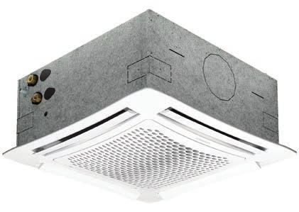
3 Introduction Innovating and beautiful design, seven different sizes, high control flexibility, easy maintenance: the new chilled water cassette is the result of an extended technical and design development aimed at achieving the highest level in terms of performance, silent operation and control possibilities. The air diffuser has an highly attractive aesthetical appearance, very innovative, and is also able to offer the best air distribution performance thanks to long computer studies and laboratory tests. The standard colour is RAL 9003, other colours available on request. The 4 smaller sizes are designed to fit into 600x600 mm false ceiling standard modules. The 3 bigger sizes have a dimension of 800x800 mm which allows the best outcome in terms of quietness and of price/performance ratio for these high capacity models. Every unit can be supplied with battery (2 pipe system) and a possible electric heater or with 2 batteries (4 pipe system). Each model can have fresh air intake and a remote air diffuser can be connected to the unit. The condensate pump is integral with the unit, is very quiet and has a maximum head of 60 mm. In addition to temperature and speed standard controls, automatic speed selection is also available. More than one unit can be connected to a single control, and the unit control panel can be installed in a remote position that facilitates the maintenance operation. All the units can be supplied in MB version. This version allows a wide range of controls, including the infra-red remote control, which can manage one single unit or several units by using the Modbus RTU - RS 48 communication protocol. The units can be connected to the most common automatic building management systems. It is also possible to use a completely wireless electronic control system based on radio communication called Free Sabiana, with great advantages in terms of installation flexibility and maximum precision in measuring room temperature. Finally, each unit can be equipped with a low energy consumption electric motor that is controlled by an inverter card that makes possible continuous air variations. 3
4 Main components INTAE GRID AND DISTRIBUTION OF THE AIR Intake grids, frame and adjustable air distribution louvers on each side, made from ABS. HTA version : white ABS, RAL 9003 HTB version : with intake grid, frame and louvers, choice of one colour only HTC version : with intake grid and louvers, choice of one colour, plus white ABS frame RAL 9003 HTD version : with louvers, choice of one colour, while the grid and frame are made from ABS, RAL 9003 MD-600 version : metal diffuser painted in RAL 9003 white colour with 600x600 dimension to perfectly fit into the false ceiling standard modules without overlapping parts (800x800 model is not available). CASING Is made from galvanized steel with internal thermal insulation with polyolefin (PO) foam (class M) and external anti-condensate lining. CONTROL PANEL Made of an external box with the control electronic board with an easily accessible terminal board. FAN ASSEMBLY The fan assembly, which is mounted on anti-vibrating supports, is extremely silent. The radial fan has been designed to optimise performance, using wing profile blades with a shape that reduces turbulence, increasing efficiency and reducing noise. The single air inlet radial fan is connected to a 6 speed electric motor with single phase 230V/0Hz supply, class B insulation and integrated lixon thermal contact for motor protection. The units are supplied with 3 standard speeds connected and it is possible to change them on site if necessary. COIL Made of copper tubes with bonded aluminium fins for maximum transfer contact. The coil has, 2 or 3 rows for 2 pipe models and 2+ rows for 4 pipe models (the heating row is on the inside part of the coil). For 4 pipe systems two versions are available: S 04, S 4, S 24, S 34, S 44, S 4, S 64 supply an higher heating emission; S 26, S 36, S 6, S 66 supply an higher cooling emission. The heat exchanger is not suitable for use in corrosive atmosphere or in environments where aluminium may be subject to corrosion. CONDENSATE COLLECTION TRAY density ABS polystyrene foam condensate tray, shaped in order to optimize the air diffusion, fire retardant rating B to DIN 402. AIR FILTER Synthetic washable filter, easily removable. CONDENSATE PUMP Float switch centrifugal pump with 60 mm of maximum head, integral to the unit and wired to the control panel on the outside of the casing. VALVE SET Two or three way valves for ON/OFF operation, with pipe mounting kit and thermostatic actuator. 4
5 EUROVENT Certific. Technical features 2 pipe units. The following standard rating conditions are used: COOLING Entering air temperature: + 27 C d.b., + 9 C w.b. HEATING Entering air temperature: + 20 C temperature: + 7/2 C temperature: + 0 C water rate as for the cooling conditions MODEL Speed Air m 3 /h Cooling total emission (E) kw Cooling sensible emission (E) kw Heating (E) kw l/h P Cooling (E) kpa P Heating (E) kpa Sound power Lw (E) db(a) Sound pressure Lp ( * ) db(a) Fan (E) content Dimensions W A l mm S ,27,0, , 4, , 420,63,32 2, ,0 6, , 0,8 60,98,64 2, ,0 9, , ,34,7 20 2,68 2, ,2,7 00 3,34 2,39 4,33 3, ,94 2, ,88 2,8 880,02 3, ,2 3, ,9 3,8 40 6,6 4,9,3 3, ,78 4, , 6,48,3 3, ,4 6,09 2,90 3,3 2,6 3,93,23 3,43 4,63 6,7,2 6,03 7,77,6 7,34 0,7 6,3 0, ,6 6, , 9,7 8, ,20 4,6 3, , 9,4 7, ,20,, ,32 7, 6, , 2,4, ,27 9,7 7, ,4 0,9 6, , 4,3 9, ,23 2,6, ,36 9,4 7, ,8 4,7 2, ,28 26,9 23, ,3 9,4 7, ,8 2,8 8, ,42 30,84,3 2, ,9 4, , S 2 S 22 S 32 S 42 S 2 S 62,4 2, 2, 3,0 4,0 4,0 7 x 7 x x 820 x ,0 8,2 4, ,6 30, ,74 4 pipe units. The following standard rating conditions are used: COOLING Entering air temperature: + 27 C d.b., + 9 C w.b. HEATING Entering air temperature: + 20 C temperature: + 7/2 C temperature: + 70/60 C MODEL S 04 S 4 S 24 S 26 S 34 S 36 Speed Air m 3 /h Cooling total emission (E) kw Cooling sensible emission (E) kw l/h P Cooling (E) kpa Heating (E) kw l/h P Heating (E) kpa Sound power Lw (E) db(a) Sound pressure Lp ( * ) db(a) Fan (E) Cooling water content Heating water content Dimensions W A l l mm ,96, 337 0,0 2,4 29 0, , 60 2,33, , 3, , ,27 30,8, ,6 2,43 209, , 420 2,36, ,9 3, , , 20 2,70, ,8 3, , ,20 320,8, ,6 2,43 209, , 00 2,6, ,8 3, , ,20 3,34 2,6 74 3,4 4, , , ,09, ,0, , , 00 3,06 2, ,0 2, , ,20 3,93 2, , 3, , , ,36, ,2 3, , , 60 3,02 2,29 9,2 3, , , ,8 2,97 6 7,0 4, , , ,72, ,0 2,46 22, , 60 3,3 2, ,0 3, , ,27 30,, 260 6,0, , ,,0 0,6 0,23 3,0,4,4 0,7 0,28 3,0,4,4 0,7 0,28 3,6, 820 x 820 x x 7 x 27 MODEL S 44 S 4 S 6 S 64 S 66 Speed Air m 3 /h Cooling total emission (E) Cooling sensible emission (E) kw kw 4,4 2,96,03 3,6 6,34 4,69 4,2 3,2,66 4, 7,7,83 4,99 3,3 6,33 4, 8,77 6,49 4,2 3,2 6,93,8 8,89 6,84 4,99 3,3 7,84,73 l/h P Cooling (E) kpa 8,8 2, 8,9 0,3,4 26,9 9,0 4,0 2,0 0,3 22, 34,7 9,0 20,0 Heating (E) kw,9 7,9 9,0 6,4 8,0,00,23 6,42 8,6 6,4 9,98 2,70,23 7,74 P Heating (E) Sound power Lw (E) Sound pressure Lp ( * ) l/h kpa db(a) 08 9, , , , , , , , ,3 3 44, , , , , Fan (E) W A 0, 0,36 0,8 0,3 0,8 0,3 0,8 0,74 0,8 Cooling water content Heating water content Dimensions l l mm Condensate pump absorption: 0 W (E) = Eurovent certified performance. (*) = The sound pressure levels are 9 db(a) lower than the sound power levels and apply to the reverberant field of a 00 m 3 room and a reverberation time of 0. sec.,7 0, 0,42 3,0,4,4 0,7 0,42 3,6, 820 0,20 7, ,0 9, , ,74,7 0, 880 4,3 3, ,0 3,79 326, ,4
6 Cooling emission of battery units (2 pipe installation) Entering air temperature: +27 C d.b. +9 C w.b. Model S 02 S 2 S 22 S 32 S 42 S 2 S 62 Speed Air m 3 /h EWT - LWT 0 C EWT 7 - LWT 2 C EWT 9 - LWT 4 C EWT 2 - LWT 7 C Total Sensible Total Sensible Total Sensible Total emission emission emission emission emission emission emission Sensible emission l/h kw kw l/h kw kw l/h kw kw l/h kw kw ,4 2,0,7 3,22 2,80 2,42,38 4, 2,9 6,0 4,8 3,68 7,3,83 4,99,30 7,99 6,22 3,24 0,0 6,22,83,48,4 2,22,9,64 3,64 2,77,94 4,7 3,26 2,44,00 3,92 3,32 7,9,27 4,06 9,0 6,68 4, ,98,63,27 2,68 2,34,84 4,33 3,34 2,2,02 3,88 2,94 6,6 4,9 4,2 9, 6,78,3,0 8,4,3,64,32,0 2,04,7,3 3,8 2,39,7 3,74 2,8 2,08 4,9 3,8 3,03 6,48 4,48 3,46 8,2 6,09 3, ,47,22 0,96 2,0,84,6 3,9 2,8 2,03 4,03 3,2 2,0 4,88 3,92 3,37 7,7,46 4,30 8,78 6,7 4,30,4,6 0,89,7,0,29 2,87 2,8,3 3,29 2,7,92 3,9 3,09 2,62,99 4, 3,20 7,,27 3, ,6 0,93 0,7,47,28,09 2,44,86,3 2,79 2,9,6 3,33 2,63 2,23,2 3,6 2,2 6,07 4, 2,2,6 0,93 0,7,47,28,09 2,44,86,3 2,79 2,9,6 3,33 2,63 2,23,2 3,6 2,2 6,07 4, 2,2 Heating emission of battery units (2 pipe installation) Entering air temperature: +20 C Model S 02 S 2 S 22 S 32 S 42 S 2 S 62 Speed Air EWT 4 - LWT 40 C EWT 0 - LWT 40 C EWT 60 - LWT 0 C EWT 70 - LWT 60 C EWT 80 - LWT 70 C m 3 /h l/h kw l/h kw l/h kw l/h kw l/h kw ,24,80,38 2,80 2,42 2,07 4,7 3,4 2,39,2 4,08 3,02 6,0,03 4,27 9,78 6,67,09,72 8,, ,37,9,46 3,0 2,69 2,3,2 3,89 2,73,86 4,8 3,42 7,26,6 4,82,06 7,62,87 3,7 9,70, ,46 2,78 2,3 4,39 3,80 3,2 7,9,43 3,79 8,2 6,42 4,77 0,2 7,92 6,72,43 0,4 8,07 8,4 3,0 8, ,6 3,66 2,80,68 4,9 4,9 9,2 6,96 4,83 0,63 8,2 6,0 3,4 0,6 8,6 9,76 3,43 0,2 23,68 7,26 0, ,67 4, 3,47 6,97,96,2,30 8,48,87 3,00 0,07 7,43 6,08 2,4 0,0 24,08 6,32 2,42 28,9 2,0 2,42 correction factors for different working conditions. Multiply the factors by the emission figures in the 7-2 C table above. Total emission Sensible emission ( C) Air ( C) ( C) Air ( C) /2 C 0/ C 4/8 C 0,82 0,6 0,3 0,89 0,63 0,4, 0,82 0,2 7/2 C 0/ C 4/8 C 0,9 0,72 0, 0,94 0,78 0,8,06 0,9 0,72 Note: the correction factors are indicative, as they are average values. 6
7 of 4 pipe units with standard cooling battery Cooling emission of 2 battery units (4 pipe installation) Entering air temperature: +27 C d.b. +9 C w.b. Model S 04 S 4 S 24 S 34 S 44 S 4 S 64 Speed Air m 3 /h EWT - LWT 0 C EWT 7 - LWT 2 C EWT 9 - LWT 4 C EWT 2 - LWT 7 C Total Sensible Total Sensible Total Sensible Total emission emission emission emission emission emission emission Sensible emission l/h kw kw l/h kw kw l/h kw kw l/h kw kw ,8 2,38,82 3,3 2,7 2,3 4,8 3,3 2,3 4,60 3,67 2,97 7,,97 4,89 9,23 6,73,3 0,67 8,27,3 2,2,73,29 2,26,83, 2,9 2,26, 3,23 2,3 2,0,2 4,00 3,24 6,3 4,3 3,6 7,43,64 3, ,33,96, 2,70 2,36,8 3,34 2,6,8 3,8 3,02 2,36 6,34,03 4,4 7,7,66 4,2 8,89 6,93 4,2,90,,,98,70,34 2,6,98,34 2,97 2,29,7 4,69 3,6 2,96,83 4, 3,2 6,84,8 3, ,78,,7 2,8,80, 2,72 2,8, 2,98 2,40,96,02 4,02 3,33 6,08 4,0 3,62 6,97,48 3,62,69,37,02,79,44,22 2,30,79,22 2,6 2,00,9 4,04 3, 2,6,02 3,7 2,8,98 4,46 2, , ,39,4 0,86,,22,03,92,,03 2,3,67,3 3,4 2,68 2,7 4,22 3,0 2,39 4,94 3,7 2,39,39,4 0,86,,22,03,92,,03 2,3,67,3 3,4 2,68 2,7 4,22 3,0 2,39 4,94 3,7 2,39 Heating emission of 2 battery units (4 pipe installation) Entering air temperature: +20 C Model S 04 S 4 S 24 S 34 S 44 S 4 S 64 Speed Air EWT 4 - LWT 40 C EWT 0 - LWT 40 C EWT 60 - LWT 0 C EWT 70 - LWT 60 C EWT 80 - LWT 70 C m 3 /h l/h kw l/h kw l/h kw l/h kw l/h kw ,49,2 0,96,6,44,4 2,04,6,4 2,34,84,44 4,48 3,4 2,9,40 3,99 3,8 6,24 4,9 3, ,6,3,0,73,,20 2,4,69,20 2,4,94, 4,76 3,77 3,,73 4,2 3,39 6,6,22 3, ,29,93,49 2,4 2,22,76 3,4 2,48,76 3,60 2,84 2,22 6,93,48 4, 8,34 6,7 4,92 9,64 7,60 4, ,03 2,4,96 3,46 3,02 2,43 4,40 3,46 2,43 4,9 3,97 3,0 9,0 7,9,9,00 8,0 6,4 2,70 9,98 6, ,78 3,7 2,44 4,7 3,63 2,87,7 4,07 2,87,93 4,67 3,63,28 8,90 7,3 3,60 0,04 7,98,74 2,37 7,98 correction factors for different working conditions. Multiply the factors by the emission figures in the 7-2 C table above. Total emission Sensible emission ( C) Air ( C) ( C) Air ( C) /2 C 0/ C 4/8 C 0,82 0,6 0,3 0,89 0,63 0,4, 0,82 0,2 7/2 C 0/ C 4/8 C 0,9 0,72 0, 0,94 0,78 0,8,06 0,9 0,72 Note: the correction factors are indicative, as they are average values. 7
8 of 4 pipe units with enhanced cooling battery Cooling emission of 2 battery units (4 pipe installation) Entering air temperature: +27 C d.b. +9 C w.b. Model S 26 S 36 S 6 S 66 Speed Air m 3 /h EWT - LWT 0 C EWT 7 - LWT 2 C EWT 9 - LWT 4 C EWT 2 - LWT 7 C Total Sensible emission emission Total Sensible emission emission Total Sensible emission emission Total Sensible emission emission l/h kw kw l/h kw kw l/h kw kw l/h kw kw ,72 3,66 2,47,46 4,24 3,24 0,49 7,0,89 2,24 9,34,89 3,29 2,,66 3,86 2,93 2,2 7,2,08 3,94 8,7 6,4 3, ,93 3,06 2,09 4,3 3,3 2,72 8,77 6,33 4,99 0,20 7,84 4,99 2,9 2,24,49 3,46 2,62,97 6,49 4, 3,3 7,68,73 3, ,07 2,4,67 3,2 2,77 2, 6,9,04 4,00 7,99 6,20 4,00 2,60,97,3 3,0 2,3,73,72 4,00 3,0 6,77,0 3, ,20,67,2 2,7,96,49 4,86 3,4 2,67,74 4,30 2,67 2,20,67,2 2,7,96,49 4,86 3,4 2,67,74 4,30 2,67 Heating emission of 2 battery units (4 pipe installation) Entering air temperature: +20 C Model S 26 S 36 S 6 S 66 Speed Air EWT 4 - LWT 40 C EWT 0 - LWT 40 C EWT 60 - LWT 0 C EWT 70 - LWT 60 C EWT 80 - LWT 70 C m 3 /h l/h kw l/h kw l/h kw l/h kw l/h kw ,62,32 0,96,83,48,9 4,8 3,4 2,6 4,79 3,79 2, ,6,32 0,97,82,48,20 4,33 3,27 2,67 6,6,22 3, ,48 2,0,47 2,80 2,27,83 6,44 4,84 3,9 7,36,83 3, ,3 2,7,98 3,79 3,06 2,46 8,6 6,42,23 9,80 7,74, ,22 3,42 2,49 4,78 3,86 3,0 0,69 8,0 6,2 2,24 9,66 6,2 correction factors for different working conditions. Multiply the factors by the emission figures in the 7-2 C table above. Total emission Sensible emission ( C) Air ( C) ( C) Air ( C) /2 C 0/ C 4/8 C 0,82 0,6 0,3 0,89 0,63 0,4, 0,82 0,2 7/2 C 0/ C 4/8 C 0,9 0,72 0, 0,94 0,78 0,8,06 0,9 0,72 Note: the correction factors are indicative, as they are average values. 8
 4 pipe installation Pressure drop for cooling battery Pressure drop for heating battery Pressure drop (kpa) Pressure drop (kpa) Pressure")
 Pressure drop for mean water temperature of 6 C, for different temperatures multiply the pressure drop figure by the correction factors in the table.")
9 side pressure drop 2 pipe installation Pressure drop for mean water temperature of 0 C, for different temperatures multiply the pressure drop figure by the correction factors in the table. C ,94 0,90 0,86 0,82 0,78 0,74 0,70 (l/h) 4 pipe installation Pressure drop for cooling battery Pressure drop for heating battery Pressure drop (kpa) Pressure drop (kpa) Pressure drop (kpa) (l/h) Pressure drop for mean water temperature of 0 C, for different temperatures multiply the pressure drop figure by the correction factors in the table. (l/h) Pressure drop for mean water temperature of 6 C, for different temperatures multiply the pressure drop figure by the correction factors in the table. C C ,94 0,90 0,86 0,82 0,78 0,74 0,70,4,08,02 0,96 0,90 Working conditions MAX. working pressure 8 bars Air Suitable relative humidity - 7% Supply Single phase 230V 0Hz Installation MAX. height: See table on page 2 MIN. entering water temperature: + C MAX. entering water temperature: + 80 C MIN. entering air temperature: 6 C MAX. entering air temperature: 40 C 9
10 Dimensions and weights S / S 2-4 / S / S (Version 600 x 600) 2 pipe units - 3. Flow, heating/cooling /2-4. Return, heating/cooling /2 4 pipe units -. Flow, heating /2-2. Return, heating /2-3. Flow, cooling /2-4. Return, cooling /2 MD-600 / MD-800 METAL DIFFUSER (RS receiver, Code , for metal diffuser for MB units) Size MD-600 MD-800 A B C , 4, Code Model S 02-2 S 04-4 S S UNIT Weights Weights packed unit unpacked unit kg kg DIFFUSER Weights Weights packed unit unpacked unit kg kg 6 3 Packed unit Dimensions A B C D mm
11 Dimensions and weights S / S / S (Version 800 x 800) 2 pipe units - 3. Flow, heating/cooling 3/4-4. Return, heating/cooling 3/4 4 pipe units -. Flow, heating /2-2. Return, heating /2-3. Flow, cooling 3/4-4. Return, cooling 3/4 PACED UNIT UNIT DIFFUSER Model S 42 S 44 S S UNIT Weights Weights packed unit unpacked unit kg kg DIFFUSER Weights Weights packed unit unpacked unit kg kg 0 6 Packed unit Dimensions A B C D mm
12 Air throw The air throw indicated in the tables must only be considered the maximum value, as it may change significantly in relation to the dimensions of the room in which the appliance is installed and the positioning of the furniture in the room. The useful throw L refers to the distance between the unit and the point where the air speed is 0.2 m/sec; if the louver has a gradient of 30 (recommended in cooling mode), the so-called Coanda effect will occur, illustrated in the first figure, while at a gradient of 4 (recommended in heating mode), there will be a downwards throw, as illustrated in the second figure. With adjustable air diffusion louvers at 30 Model S S S S S S Speed Air throw L m ,0 3, 3,8 3,0 3,8 4, 3, 4,2,0 3,2 3,7 4,3 3,4 4,0,0 3,4 4,6, With adjustable air diffusion louvers at 4 Model S S S S S S Speed Air throw L m Height H m Distance B m ,3 2,2 2, 3,9 2,6 2,9 4,2 2,8 3, 3,3 2,2 2, 4,2 2,8 3, 4,8 3,2 3,6 3,9 2,6 2,9 4, 3,0 3,4,2 3,4 3,9 3, 2,2 2,7 4, 2,6 3,2 4,8 3,0 3,8 3,8 2,4 3,0 4,6 2,8 3,6,4 3,4 4,2 3,8 2,4 3,0, 3, 4,0,8 3,6 4,6 NOTE: On heating it must be payed attention to rooms where the floor temperature is particularly low (for example less than C). In this situation the floor can cool the lower layer of air to a level that stop the uniform diffusion of the hot air coming from the unit, decreasing the throw figures shown in the table. 2


13 Fresh air supply - Fresh air connection The cassette is fitted with inlets for fresh air to be mixed with return air inside the unit (Fig. 3). FRESH AIR INLET The fresh air is limited to 20% of the total fan coil air at medium speed and 00 m 3 /h for each treated air inlet. The units feature fresh air inlets on three corners (no inlets on the fourth corner because of the condensate pump inside the unit). AIR INTAE Fresh air connection The fresh air inlets are designed for the insertion of standard 0 x mm rectangular ducts. The air duct is connected quickly and easily. After removing the blank and the insulation inside the unit, the mounting plate is rolled back and the air duct with its V-shaped section must be pushed into the unit (see Figures below). The duct is then fixed to the mounting plate. Note: the fresh air must be filtered MAIN AIR INLET Accessory Fresh air connection - Identification CAP - Code (see page 4) AIR INTAE Air distribution - Air distribution connection Two air outlets are provided on the side of the unit for connection to separate supply air outlets. AIR OUTLET They can be used to supply air from the fan coil unit to distant areas of a room or even to a different room. The total air does not change. The air at high speed depending on the air duct pressure drop is shown in the tables below. Note: all air ducts must be insulated in order to avoid condensation. Pressure drop (Pa) Spigot for air distribution AIR INTAE No. used outlets = No. used outlets = 2 Air (m 3 /h) Air (m 3 /h) Pressure drop (Pa) Pressure drop (Pa) Pressure drop (Pa) Air (m 3 /h) Air (m 3 /h) 3
14 Accessories Fresh air connection See page 3. Identification Code CAP Air distribution connection See page 3. Identification Code CDA CDA The diameter of the fitting is 0 mm for S and 80 mm for S Fresh air kit This is used to introduce fresh air into the environment directly through the diffuser. The kit includes a separator to be fitted inside the cassette, and a circular fitting for connection to the flexible system ducting. The of air is sent directly to just one of the outlet louvers, without passing through the coil. The air of fresh air introduced Model Identification S PRT 600 S 4--6 PRT 800 into the environment depend on the inlet static pressure Code Correlation between -rate / static pressure S S 4--6 m 3 /h Pa m 3 /h Pa The diameter of the fitting is 0 mm for S and 80 mm for S Units with remote electric board On request the Skystar cassettes are available with electric control panel reachable from below and with the electric board that can be placed in a remote position. In this case the units are supplied with an electronic connecting control panel, fitted to the bottom side on the 4 smallest sizes and to the lateral side on the 3 biggest sizes. The electronic control panel is connected to the fan motor, to the condensate pump and to the condensate level control. A 6 m wire is also supplied with integral plug-in connections to connect the unit with the remote electric board that can be installed in a suitable and comfortable position, where the power and system connections can be made easily. This feature is not available for units with electric heater or infrared remote control. 4


15 Accessories ON-OFF valves with thermoelectric actuator 3 ways 2 ways Valve with Micrometric Lockshield Valve Valve with Simplified it 3 ways 2 ways Technical data: Rated pressure: 6 bar Max. ambient temperature: 0 C Max. water temperature: 0 C Power: 230 V - 0/60 Hz Rating: 3 VA Protection: IP 43 Travel time: approx. 3 min. Max. glycol content of water: 0% Valves pressure drop Valves characteristics Battery type Main Auxiliary Model vs m 3 /h 2,8,2 2,8 2 way valves 3 way valves pmax kpa * Valve ** connection vs m 3 /h pmax kpa * * maximum pressure difference for valve to close ** external thread, flat seal Note: 3 way valves with simplified kit and connection have conical seal /4" " 3/4" 2, 4, 2, Valve ** connection 3/4" " 3/4" p - kpa Valve set, 2 or 3 ways, ON-OFF, with thermoelectric actuator. The set includes connection pipes. Note: The main battery lockshield valve connection is /2 female (vs 2) for S0 - S - S2 - S3 sizes and 3/4 female (vs 3,) for S4 - S - S6 sizes, the auxiliary battery valve connection is /2 female (vs 2). (l/h) Note: The maximum pressure drop accross the fully open valve should not exceed 2 kpa for cooling operation and kpa for heating operation.

16 Accessories Balancing valves independent from the system pressure The balancing valve and a combined 2 way valve allow the regulation of the water value autonomously, regardless of the system pressure, and the control of the by using an ON/OFF electro-thermal actuator. The balancing valve allows you to balance the hydraulic system by supplying the required water, for each fan- coil, and to maintain it even under partial load conditions. A graduated ring nut placed under the valve allows you to set the rate value and also allows direct reading of the set value. Valve operation logic p is the valve inlet pressure. p3 is the outlet pressure. p2 is the diaphragm activation pressure, which allows differential pressure p2 p3 to be maintained at a constant value, in order to guarantee the water to at the set value. The minimum differential pressure p p3, required to guarantee the correct value of the set water rate, is indicated in the diagrams on page 7. This is an essential factor to size the system pressure drop and pump pressure head. The rate is kept at a constant value only if the valve pressure drop is higher than the indicated value. Minimum operating differential pressure The minimum differential pressure and the balancing valve pressure drop must be considered to size the system pumps. Flow rate is constant if the pressure drop is higher than that indicated in the diagrams on page 7. The following diagram shows an example of the rate trend according to the pressure drop and calibration required. Example DN Model 6 LEGEND: Qw = rate (l/h) Pd = Min. differential pressure p p3 (bar) Q = Area with inconstant water Q2 = Area with constant water S = Position of the adjustment valve plunger M = Position of the knob
 E.g.")
 for each balancing valve.")

17 Accessories The valve upstream-downstream minimum differential pressure ( p p3 ), which depends on the valve calibration value, must be exceeded to access the constant rate field. DN Model DN 20 Model LEGEND: Pd = Min. differential pressure p p3 (bar) E.g., when sizing the system pump, in which the DN valves will be installed and in which 40 l/h are constantly required for each device, consider a useful pressure of 0.3 bar (to compensate the pressure drop of the valve) for each balancing valve. Therefore, the pressure drop values produced by the system balancing valves must be summed and the pump must be sized to produce a pressure equal to or greater than the value obtained previously. Benefits Reduced dimensions. Easy installation on 2 or 4 pipe devices. Pre-regulation of the nominal value set even with installed actuator. Easy display of the nominal value set. Nominal values are indicated in 0 l/h without any conversion. Guarantee of constant rate set even with partial loads. Pre-regulation can be blocked and leaded with the locking ring. Technical features DN Model Flow Rate Range (l/h) vs DN 0 00,8 DN , Operation limits of the balancing valves Maximum operating temperature 20 C Maximum operating pressure 6 bar Maximum % of water/glycol mixture 0% Minimum operating temperature -0 C Maximum differential pressure 4 bar 7
18 Accessories Balancing valves for main coil 2 way valve for main coil and assembly kit. The valve is supplied equipped with 230 Volt electro-thermal actuator for the ON/OFF control. S /4 (A) 3/4 (B) 3/4 (B) 3 0 3/4 (A) S 4 S /4 (B) (B) 3/4 (A) (A) (B) 3/4 (B) /4 (A) 3/4 (A) LEGEND A = inlet - Female connection B = outlet - Male connection Model DN Ø VALVE Flow Rate Range (l/h) Code FITTED Identification Code 3/ V2OVS6BPM / V2OVS8BPM V2OVS8BPM NOT FITTED Identification V2OVS6BPS 0-00 V2OVS8BPS 0-00 V2OVS8BPS
19 Accessories Balancing valves for main and additional coil 2 way valve for additional coil and assembly kit. The valve is supplied equipped with 230 Volt electro-thermal actuator for the ON/OFF control. S /4 (A) 3/4 (C) 3/4 (D) /4 (C) 3/4 (A) 3/4 (B) S 4 S /4 (C) (C) 3/4 (A) 3/4 (A) 3/4 (B) (B) /4 (D) LEGEND A = inlet (main coil) - Female connection B = outlet (main coil) - Male connection C = inlet (additional coil) - Female connection D = outlet (additional coil) - Male connection 3/4 (D) Coil Main Additional Model DN Ø VALVE Flow Rate Range (l/h) Code FITTED Identification Code 3/ V2OVS6BPM / V2OVS8BPM V2OVS8BPM / V2OVS6BAM / V2OVS8BAM NOT FITTED Identification V2OVS6BPS 0-00 V2OVS8BPS 0-00 V2OVS8BPS V2OVS6BAS 0-00 V2OVS8BAS


20 Crystall Introduction Cassette can be equipped with the innovative plate type electrostatic filter, Crystall, combining air treatment and purifying in a single product. The electronic filter is patented and certified according to Standard UNI 24. Dimensions S 0 / / 2 / 3 (Model 600 x 600) S 4 / / 6 (Model 800 x 800) 20
 are exposed to an intensive ionizing field and are polarized (Phase ).")
. The air which leaves the unit is free from polluting particles.")
21 Crystall Operating principle of the electrostatic filter When the polluted air goes through the mechanical pre-filter the particles 0 µ are eliminated (powder, insects, etc). OUTLET OF CLEAN AIR Collection surface Then the smallest particles (0 0.0 μm) are exposed to an intensive ionizing field and are polarized (Phase ). Air without particles < µm PHASE 2 Inducted anode Polarized electrode The charged particles passing through the second filter section, are pushed back by the anode and attracted to the collection surfaces by a strong, induced magnetic field (Phase 2). The air which leaves the unit is free from polluting particles. Electrostatic filter Air without particles 0 µm Pre-filter PHASE Ionic field Elimination of the biggest particles INLET OF POLLUTED AIR Indoor air quality (IAQ) The expression Indoor Air Quality (IAQ) covers all the procedures and methodologies used to improve the quality of the air we breathe in the places where we live and work, from all points of view, from temperature to cleanliness, to relative humidity, etc. (EN 2 and EN 3779). Thanks to its new patented electronic filter, the Crystall electrostatic filter totally eliminates the pollutants present in the air, including tobacco smoke, dust (PM0, PM2.), fibres, microbiological substances such as bacteria, fungi, etc., which are harmful to human health (source: OMS 2009). Purifying the air means not only greater well-being, but also energy saving, as the fresh air changes that are required to restore ideal climatic conditions and that entail greater consumption, are significantly reduced (it is sufficient to enter the quantity of air required to restore the optimum level of CO 2 - source: EN 379:2008). Moreover, according to the UNI 0339rev, air recirculated by the Crystall appliance can be considered as fresh air, to be added to the minimum requirements (0, ls/m2). Purifying the air with the Sabiana Crystall appliance also entails no reduction of living room space, as the dimensions of the fan convector are practically unchanged (just 3 cm higher). The positioning of the electronic filter allows simple and effective maintenance and, as it is easy to wash, its working life is practically unlimited. The modularity of the filter components and their ease of mounting make the system extremely competitive in terms of cost compared with other types of filters present on the market. In spring and autumn, if air conditioning/heating is not required, the appliance acts simply as an air purifier. Standards and legislation THE AMBIENT CONDITION IS ACCEPTABLE WHEN: Microclimatic parameters are normal 80% of people are satisfied by the quality of air Specific internal contaminants are not in harmful concentrations Guidelines for the protection and promotion of health in confined areas O.G. No. 276 dated 27 Nov 0 ordinary supplement no. 22 The method for obtaining the air quality required in confined areas and thus succeeding in ensuring that the contaminants present are in concentrations less than those considered dangerous to health are: Prescriptive approach: ventilation of the internal area using only properly filtered fresh air, in the quantity and quality needed to dilute the internal contaminants in order to reach the required maximum acceptable concentration values (see WHO limits). Performance approach: ventilation with fresh air and recirculated air from the same area, both properly filtered, in the quantity and quality needed to dilute the internal contaminants in order to reach the required maximum acceptable concentration values (see WHO limits). 2
22 Crystall The quantity and quality of recirculated air and outdoor air to be added is better specified in the prescriptive and performance approach in Standards UNI EN 3779:2008 and soon to be released UNI 0339rev according to the following simplified tables. UNI EN 3779:2008 Prescriptive Method Category IDA IDA 2 IDA 3 IDA 4 Category ium not classified Unit l.s. person l.s. person l.s. person l.s. person UNI EN 0339rev (l.s. per person) + (l.s. per m 2 ) (l.s. per person) + (l.s. per m 2 ) (l.s. per person) + (l.s. per m 2 ) not classified Tipical range > < 6 Rate of fresh air Rate of fresh air Default value 20 2, 8 Total fresh air volume varies based on the intended use of the confined area UNI EN 3779:2008 Identification and quantification of the reference pollutant (PM or gas) Performance Method Concentration Limit WHO publicized values and legislative acts expressed in µg/m 3, PPM, etc. Concentration Limit WHO publicized values and legislative acts expressed in µg/m 3, PPM, etc. Minimum fresh air l.s. person - 6 UNI EN 0339rev Minimum fresh air l.s. person The minimum volume of air input varies based on the intended use of the confined area Quantity of recirculated air provided that it is filtered like fresh air The volume of air to be considered is based on the internal production and the imposed concentration limits in the confined area Identification and quantification of the reference pollutant (PM or gas) Quantity of recirculated air provided that it is filtered like fresh air The volume of air to be considered is based on the internal production and the imposed concentration limits in the confined area Fresh air rates according to the performance approach UNI EN 3779:2008 and UNI 0339rev Standards The example reproduced at the bottom of the page shows how, with adequate air filtering, it is possible to decrease considerably the quantity of fresh air to be brought into the environment (up to 3-4 times less); the thermal energy dissipated due to ventilation is in fact in direct proportion to the number of air changes, as indicated in the following equation: Qv = T R D C Vol Qv = Thermal energy lost for ventilation - Watt T = Indoor-Outdoor difference (T) - C R = A.C.H. D = Air density - g/m 3 C = Specific air heat - J/g- C Vol = Room size - m 3 22

23 Crystall Construction features The Crystall electrostatic filtering system consists of two parts: the first is a plate type electronic active filter and is fitted in the return air section of the cassette, while the second is an electronic control and regulation board, fixed on the structure. All electrical connections are made during production. The installation of the Sabiana cassette fan coil unit incorporating the Crystall electronic filter is therefore similar to that of a normal unit: the only difference is the installation height, for which the filter dimensions must taken into account. Crystall filters are not suitable for ECM and electric heater versions. Active plate type electronic filter The filtering element consists of two sections: the first consists of electrodes and insulating elements, forming a self-supporting ionising frame, while the second consists of special light aluminium fins (collector). The two sections are installed above the return air grille to make the extraction and maintenance of the filter easier. Accessibility to sections to be cleaned is ensured by easy-open plastic closures. The collector can be cleaned by washing with water and ordinary detergents or steam jets (please consult the maintenance manual for further details). Electronic board Controls and regulates all functions of the electrostatic filter. It is appropriately protected against any operating defects of the electrostatic filter. It supplies a constant voltage to the electrodes when the mains supply voltage varies (± %). The supply transformer is constructed with its primary and secondary coils physically separated and wound onto separate cores. The energy consumption of the filter group is 2 W (to which the electrical consumption of the Cassette must be added). Control and regulation commands Units with Crystall electrostatic filter can be controlled and regulated by the series of IAQ controls that are already provided for CRC Carisma fan coils. - Diffuser with return air grid 2 - Active plate type electrostatic filter 3 - Plastic opening 4 - Insulation - Filter containment frame 6 - Electronic board 7 - Cassette 23


24 Wall electronic controls All the units can be supplied with a wide range of controls that allows managing one single unit or several units (by using speed switches or the power unit). The room temperature can be controlled through electronic room thermostats, with different solutions according to every ambient conditions. The options range from the basic 3 speed control WM-3V to the highly sophisticated WM-T and WM-TQR electronic room thermostats that regulate the room temperature and are suitable when the user wants to set the fan speed. The most evolved WM-AU, T-MB, TMO-03-SV2 and FreeSabiana versions allow both the manual and the automatic speed switch. WM-3V WM-T WM-TQR WM-AU T-MB TMO-03-SV2 T2T FreeSabiana wireless control All the controls are described in detail in the Fan Coil Control Range literature. 24
25 Controls for S MB versions All the units can be supplied in MB version. This version includes a wide range of controls, including the infra-red remote control, which allows managing one single unit or several units by using the Modbus RTU - RS 48 communication protocol. Units can be managed according to the Master/Slave logic (up to 20 units) or by supervisory components. The system consists in a MB board (mounted on models S MB and S ECM MB) and a series of controls, such as the T-MB wall control, the RT03 infra-red remote control, the PSM-DI multifunction control and the Sabianet supervisory program. T-MB wall control PSM-DI multifunction control Sabianet screenshot PC RT03 infra-red remote control Sabianet software All the controls are described in detail in the Fan Coil Control Range literature. 2
26 Electric heater S-E The Cassette 2 pipe models are available with electric resistance that is controlled in place of the heating battery valve. The electric resistance is controlled in place of the hot water valve and not as integration to it. The resistance is hermetically sealed and supplied inside the battery pipes and therefore can be only factory mounted. The electric resistances of the units are for single phase 230V supply. The Cassette includes no. 2 safety thermostats which intervene in case of internal over- heating, opening an auxiliary power relay (included in the shunt box) which stops the power supply to the resistances. Model Supply Number and Dia. of connecting wires S 2-E S 22-E / S 32-E S 42-E / S 2-E / S 62-E 00 Watt 230V ~ 3 x, mm Watt 230V ~ 3 x 2, mm Watt 230V ~ 3 x 2, mm 2 Note: the cooling emission of the units is 9% of the emission in the tables of page 6. Electric diagram T POWER SUPPLY 230Vac 0Hz PE Q L N TS TS2 B 2 N L 3 M M7 B B BN OG WH 2 -level ALARM 8 M9 J3 J 9 0 M B BN BU J Thermostat ALARM BU BN J4 SEC WH WH 23 4 M6 C MM L M RD OG M EH M0 M9 M8 B V V2 V3 J2 V M4 V2 V3 2 L3 N L2 N L N L3 M2 L2 L M L N 3 4 R3 R2 R POWER SUPPLY 230Vac 0Hz Q2 L N LEGEND: M = Fan SEC = Fan coil terminal board T C = Autotransformer = Capacitor B = Condensate level sensor M9 = pump motor S = Alarm condensate contact E = Cold water valve B = Black BN = Brown BU = Dark Blue OG = Orange RD = Red WH = White R-R2-R3 = Resistance Q-Q2 = Two poles disconnector Input for electric resistance Input for E speed ium speed E speed TS TS2 Safety thermostat TS TS2 Thermal cut Off = 4 C Thermal cut Off = 80 C Automatic Reset Manual Reset Cassette unit operating limits with electric coil Max. ambient temperature for Cassette unit with electric coil in heating mode: 2 C 26

27 ECM / ECM 27
28 ECM ECM Introduction The ECM series uses an innovative brushless synchronous permanent magnet electric motor controlled by an inverter card that is directly installed on the unit. The air can be varied continuously with a -0 V signal from Sabiana controls or by independent contollers (programmable controllers with a -0 V output). The extreme efficiency, also at a low speed, makes possible a great reduction in electric consumption (more than 7% less in comparison to a traditional motor) with absorption values, under normal operating conditions, that are no greater than 0 Watt in the entire range. The brushless motor is characterised by a constant synchronous speed, independently of the applied load, that depends only on the motor power supply frequency, which is modulated by the inverter. It consumes less because: The motor always works at its point of maximum efficiency. In the brushless motor, the rotor s permanent magnets generate the magnetising power autonomously. The motor always operates at the synchronous speed, as a result there are no induced currents that reduce efficiency. The main advantages are: Large reduction in energy consumption, thanks to an optimal response to the thermal load of the environment during every moment of the day. Operating silence at all rotation speeds. Ability to operate at any rotation speed. Motor Absorption = S = S-ECM 28
29 ECM ECM Main components INTAE GRID AND DISTRIBUTION OF THE AIR Intake grids, frame and adjustable air distribution louvers on each side, made from ABS. HTA version : white ABS, RAL 9003 HTB version : with intake grid, frame and louvers, choice of one colour only HTC version : with intake grid and louvers, choice of one colour, plus white ABS frame RAL 9003 HTD version : with louvers, choice of one colour, while the grid and frame are made from ABS, RAL 9003 MD-600 version : metal diffuser painted in RAL 9003 white colour with 600x600 dimension to perfectly fit into the false ceiling standard modules without overlapping parts (800x800 model is not available). CASING Is made from galvanized steel with internal thermal insulation with polyolefin (PO) foam (class M) and external anti-condensate lining. CONTROL EQUIPMENT S ECM version It consists of the pump control circuit board and the inverter circuit board. S ECM MB version It consists of the MB electronic board (that integrates pump control) and the inverter board. FAN ASSEMBLY The fan assembly, which is mounted on anti-vibrating supports, is extremely silent. The radial fan has been designed to optimise performance, using wing profile blades with a shape that reduces turbulence, increasing efficiency and reducing noise. The fans are connected to a three phase permanent magnet brushless electronic motor that is controlled with reconstructed current according to a BLAC sinusoidal wave. The inverter board that controls the motor operation is powered by 230 Volt, single-phase and, with a switching system, it generates a three-phase frequency modulated, wave form power supply. The electric power supply required for the machine is therefore single-phase with voltage of V and frequency of 0-60 Hz. COIL Made of copper tubes with bonded aluminium fins for maximum transfer contact. The coil has 2 or 3 rows for 2 pipe models and 2+ rows for 4 pipe models (the heating row is on the inside part of the coil). For 4 pipe systems two versions are available: S 4 and S 44 supply an higher heating emission; S 26, S 36, S 6 supply an higher cooling emission. The heat exchanger is not suitable for use in corrosive atmosphere or in environments where aluminium may be subject to corrosion. CONDENSATE COLLECTION TRAY density ABS polystyrene foam condensate tray, shaped in order to optimize the air diffusion, fire retardant rating B to DIN 402. AIR FILTER Synthetic washable filter, easily removable. CONDENSATE PUMP Float switch centrifugal pump with 60 mm of maximum head, integral to the unit and wired to the control panel on the outside of the casing. VALVE SET Two or three way valves for ON/OFF operation, with pipe mounting kit and thermostatic actuator. 29

30 ECM ECM EUROVENT Certification Technical features 2 pipe units. The following standard rating conditions are used: COOLING Entering air temperature: + 27 C d.b., + 9 C w.b. temperature: + 7/2 C HEATING Entering air temperature: + 20 C temperature: + 0 C water rate as for the cooling conditions MODEL S-ECM 2 S-ECM 22 S-ECM 32 S-ECM 42 S-ECM 2 Inverter Power Vdc Speed Air m 3 /h Cooling total emission (E) kw,84 2,7 2,7 2,24 3,0 4,33 2,6 3,87,02 4,2, 6,33,29 7,72 0,7 Cooling sensible emission (E) kw,3,6 2,09,7 2,7 3,8,8 2,8 3,74 3,03 3,77 4,72 3,69,3 7,94 Heating (E) kw 2,22 2,67 3,44 2, 3,8,24 2,96 4,63 6,2, 6,3 8,0,89 8,83 2,73 l/h P Cooling (E) kpa 4,9 6,6 0, 4,6 9,4,,9 2,4 9,7 0,9,6 22,7 9,4 8, 33,6 P Heating (E) kpa 4, 8,7 3,6 6,6 3, 4,7 0, 7,7 8,7 2,8 9, 7,2 4,9 28,8 Sound power Lw (E) db(a) Sound pressure Lp ( * ) db(a) Fan (E) W content l,4 2, 2, 3,0 4,0 Dimensions mm 7 x 7 x x 820 x pipe units. The following standard rating conditions are used: COOLING Entering air temperature: + 27 C d.b., + 9 C w.b. temperature: + 7/2 C HEATING Entering air temperature: + 20 C temperature: + 70/60 C MODEL S-ECM 4 S-ECM 26 S-ECM 36 S-ECM 44 S-ECM 6 Inverter Power Vdc Speed Air m 3 /h Cooling total emission (E) kw,8 2,8 2,77 2,09 2,8 3,93 2,38 3,3 4,3 4,3,28 6, 4,98 7,7 Cooling sensible emission (E) kw,34,6 2,08,49 2,04 2,9,7 2,62 3,46 3,08 3,84 4,83 3,2,2 l/h P Cooling (E) kpa 4,6 6,2 9, 3,,7 0, 4, 8,4 3, 9,4 3,6 9,8 8,8 7 Heating (E) kw 2,43 2,8 3,62,98 2,3 3,3 2,2 3,06 3,79 6,4 7,4 9,36,22 7,6 l/h P Heating (E) kpa,7 7,6,7 3,, 9 4, 7, 0,, 22, 6, Sound power Lw (E) db(a) Sound pressure Lp ( * ) db(a) Fan (E) W Cooling water content l,4,7,7 3,0 3,6 Heating water content l 0,7 0, 0,,4, Dimensions mm 7 x 7 x x 820 x 303 Condensate pump absorption: 0 W (E) = Eurovent certified performance. * = The sound pressure levels are 9 db(a) lower than the sound power levels and apply to the reverberant field of a 00 m 3 room and a reverberation time of 0. sec ,87 7, , 9,
31 ECM ECM Cooling emission of battery units (2 pipe installation) Entering air temperature: +27 C d.b. +9 C w.b. ECM Mod. S 2 S 22 S 32 S 42 S 2 Speed Vdc Air m 3 /h EWT - LWT 0 C EWT 7 - LWT 2 C EWT 9 - LWT 4 C EWT 2 - LWT 7 C Total Sensible emission emission l/h kw kw ,32 2,60 2,2,7 3,6 2,63 6,02 4,6 3,02 7,8 6,3 4,99 2,8 9, 6,2 2,33,80, 3, 2,43,7 4,8 3, 2,02,27 4,2 3,39 8,88 6,8 4,2 Total Sensible emission emission l/h kw kw ,7 2,7,84 4,33 3,0 2,24,02 3,87 2,6 6,33, 4,2 0,7 7,72,29 2,09,6,3 3,8 2,7,7 3,74 2,8,8 4,72 3,77 3,03 7,94,3 3,69 Total Sensible emission emission l/h kw kw ,4,70,4 3,42 2,43,8 3,94 3,07 2,06 4,98 4,07 3,3 8,47 6,6 4,27,84,42,8 2,80,9,38 3,30 2,48,9 4,7 3,32 2,67 7,00 4,86 3,24 Total Sensible emission emission l/h kw kw ,4,2,0 2,38,63,8 2,80 2,,37 3, 2,8 2,28,99 4,8 2,80,4,2,0 2,38,63,8 2,80 2,,37 3, 2,8 2,28,99 4,8 2,80 Heating emission of battery units (2 pipe installation) Entering air temperature: +20 C ECM Mod. S 2 S 22 S 32 S 42 S 2 Speed Vdc Air m 3 /h EWT 4 - LWT 40 C EWT 0 - LWT 40 C EWT - LWT 4 C EWT 60 - LWT 0 C EWT 70 - LWT 60 C l/h kw 2,87 2,22,8 4,36 2,98 2,2, 3,8 2,46 6,70,30 4,27 0,6 7,34 4,90 l/h kw 3,7 2,48 2,07 4,89 3,38 2,43,7 4,34 2,8 7,47,9 4,82,8 8,29,60 l/h kw 3,83 2,99 2,49,87 4,04 2,90 6,92,20 3,3 9,00 7,,78 4,2 9,93 6,67 l/h kw 4,49 3,49 2,9 6,8 4,70 3,36 8,09 6,07 3,89 0, 8,34 6,72 6,60,6 7,74 l/h kw,82 4, 3,7 8,8 6,0 4,28 0,42 7,79 4,96 3,4 0,72 8,6 2,37 4,82 9,87 correction factors for different working conditions. Multiply the factors by the emission figures in the 7-2 C table above. Total emission Sensible emission Note: ( C) Air ( C) ( C) Air ( C) /2 C 0/ C 4/8 C 0,82 0,6 0,3 0,89 0,63 0,4, 0,82 0,2 7/2 C 0/ C 4/8 C 0,9 0,72 0, 0,94 0,78 0,8,06 0,9 0,72 the correction factors are indicative, as they are average values. 3
32 ECM ECM of 4 pipe units with standard and enhanced cooling battery Cooling emission of 2 battery units (4 pipe installation) Entering air temperature: +27 C d.b. +9 C w.b. ECM Mod. S 4 S 26 S 36 S 44 S 6 Speed Vdc Air m 3 /h EWT - LWT 0 C EWT 7 - LWT 2 C EWT 9 - LWT 4 C EWT 2 - LWT 7 C Total Sensible emission emission l/h kw kw ,32 2,6 2,20 4,72 3,3 2,47,46 4,24 2,82 7,79 6,29,0,83 8,3,87 2,32,79,0 3,29 2,28,66 3,86 2,93,9,40 4,30 3,4 8,26,82 3,93 Total Sensible emission emission l/h kw kw ,77 2,8,8 3,93 2,8 2,09 4,3 3,3 2,38 6,,28 4,30 9,87 7,7 4,98 2,08,60,34 2,9 2,04,49 3,46 2,62,7 4,83 3,84 3,08 7,40,20 3,2 Total Sensible emission emission l/h kw kw ,7,72,46 3,07 2,22,67 3,2 2,77,89,3 4,8 3,43 7,74,69 3,99,83,4,8 2,60,79,3 3,0 2,3,0 4,26 3,38 2,7 6,3 4,8 3,09 Total Sensible emission emission l/h kw kw ,4,20,00 2,20,3,2 2,7,96,29 3,6 2,89 2,32,3 3,90 2,66,4,20,00 2,20,3,2 2,7,96,29 3,6 2,89 2,32,3 3,90 2,66 Heating emission of 2 battery units (4 pipe installation) Entering air temperature: +20 C ECM Mod. S 4 S 26 S 36 S 44 S 6 Speed Vdc Air m 3 /h EWT 4 - LWT 40 C EWT 0 - LWT 40 C EWT - LWT 4 C EWT 60 - LWT 0 C EWT 70 - LWT 60 C l/h kw,78,40,9,62,23 0,96,83,48,07 4,6 3,72 3,03 4,6 3,0 2,6 l/h kw,87,48,26,6,23 0,97,82,48,08 4,90 3,96 3,23 4,80 3,63 2,67 l/h kw 2,30,82, 2,04,,22 2,3,87,36 6,0 4,8 3,96,97 4, 3,30 l/h kw 2,74 2,6,84 2,48,87,47 2,80 2,27,64 7,3,7 4,68 7,,39 3,94 l/h kw 3,62 2,8 2,43 3,3 2,3,98 3,79 3,06 2,20 9,36 7,4 6,4 9, 7,6,22 correction factors for different working conditions. Multiply the factors by the emission figures in the 7-2 C table above. Total emission Sensible emission Note: ( C) Air ( C) ( C) Air ( C) /2 C 0/ C 4/8 C 0,82 0,6 0,3 0,89 0,63 0,4, 0,82 0,2 7/2 C 0/ C 4/8 C 0,9 0,72 0, 0,94 0,78 0,8,06 0,9 0,72 the correction factors are indicative, as they are average values.
 4 pipe installation Pressure drop for cooling battery Pressure drop for heating battery Pressure drop (kpa) Pressure drop (kpa) Pressure")
33 ECM ECM side pressure drop 2 pipe installation Pressure drop for mean water temperature of 0 C, for different temperatures multiply the pressure drop figure by the correction factors in the table. C ,94 0,90 0,86 0,82 0,78 0,74 0,70 (l/h) 4 pipe installation Pressure drop for cooling battery Pressure drop for heating battery Pressure drop (kpa) Pressure drop (kpa) Pressure drop (kpa) (l/h) Pressure drop for mean water temperature of 0 C, for different temperatures multiply the pressure drop figure by the correction factors in the table. (l/h) Pressure drop for mean water temperature of 6 C, for different temperatures multiply the pressure drop figure by the correction factors in the table. C C ,94 0,90 0,86 0,82 0,78 0,74 0,70,4,08,02 0,96 0,90 Working conditions MAX. working pressure 8 bars Air Suitable relative humidity - 7% Supply Single phase 230V 0Hz Installation MAX. height: See table on page 2 MIN. entering water temperature: + C MAX. entering water temperature: + 80 C MIN. entering air temperature: 6 C MAX. entering air temperature: 40 C 33
34 ECM ECM Dimensions and weights S 2-4 / S / S (Version 600 x 600) 2 pipe units - 3. Flow, heating/cooling /2-4. Return, heating/cooling /2 4 pipe units -. Flow, heating /2-2. Return, heating /2-3. Flow, cooling /2-4. Return, cooling /2 MD-600 / MD-800 METAL DIFFUSER (RS receiver, Code , for metal diffuser for MB units) Size MD-600 MD-800 A B C , 4, Code ECM Model S 2 S 4 S S UNIT Weights Weights packed unit unpacked unit kg kg DIFFUSER Weights Weights packed unit unpacked unit kg kg 6 3 Packed unit Dimensions A B C D mm
35 ECM ECM Dimensions and weights S / S 2-6 (Version 800 x 800) 2 pipe units - 3. Flow, heating/cooling 3/4-4. Return, heating/cooling 3/4 4 pipe units -. Flow, heating /2-2. Return, heating /2-3. Flow, cooling 3/4-4. Return, cooling 3/4 PACED UNIT UNIT DIFFUSER ECM Model S 42 S 44 S 2-6 UNIT Weights Weights packed unit unpacked unit kg kg DIFFUSER Weights Weights packed unit unpacked unit kg kg 0 6 Packed unit Dimensions A B C D mm
36 ECM ECM Air throw The air throw indicated in the tables must only be considered the maximum value, as it may change significantly in relation to the dimensions of the room in which the appliance is installed and the positioning of the furniture in the room. The useful throw L refers to the distance between the unit and the point where the air speed is 0.2 m/sec; if the louver has a gradient of 30 (recommended in cooling mode), the so-called Coanda effect will occur, illustrated in the first figure, while at a gradient of 4 (recommended in heating mode), there will be a downwards throw, as illustrated in the second figure. With adjustable air diffusion louvers at 30 ECM Model Speed Air throw L m S 2-4 S S S S ,0 3, 3, ,0 3,8 4, 2 3 3, 4,2, ,2 3,7 4, ,4 4,0,0 With adjustable air diffusion louvers at 4 ECM Model Speed Air throw L m Height H m Distance B m S 2-4 S S S S ,3 2,2 2, 3,9 2,6 2,9 4,2 2,8 3, 3,3 2,2 2, 4,2 2,8 3, 4,8 3,2 3,6 3,9 2,6 2,9 4, 3,0 3,4,2 3,4 3,9 3, 2,2 2,7 4, 2,6 3,2 4,8 3,0 3,8 3,8 2,4 3,0 4,6 2,8 3,6,4 3,4 4,2 NOTE: On heating it must be payed attention to rooms where the floor temperature is particularly low (for example less than C). In this situation the floor can cool the lower layer of air to a level that stop the uniform diffusion of the hot air coming from the unit, decreasing the throw figures shown in the table. 36
37 ECM ECM Accessories Fresh air connection See page 3. Identification Code CAP Air distribution connection See page 3. Identification Code CDA CDA The diameter of the fitting is 0 mm for S and 80 mm for S 4 -. Fresh air kit This is used to introduce fresh air into the environment directly through the diffuser. The kit includes a separator to be fitted inside the cassette, and a circular fitting for connection to the flexible system ducting. The of air is sent directly to just one of the outlet louvers, without passing through the coil. The air of fresh air introduced Model Identification S -2-3 PRT 600 S 4- PRT 800 into the environment depend on the inlet static pressure Code Correlation between -rate / static pressure S -2-3 S 4- m 3 /h Pa m 3 /h Pa The diameter of the fitting is 0 mm for S and 80 mm for S


38 ECM ECM ON-OFF valves with thermoelectric actuator Valve with Micrometric Lockshield Valve 3 ways 2 ways Valve with Simplified it 3 ways 2 ways Technical data: Rated pressure: Max. ambient temperature: Max. water temperature: Power: Rating: Protection: Travel time: Max. glycol content of water: p - kpa 6 bar 0 C 0 C 230 V - 0/60 Hz 3 VA IP 43 approx. 3 min. 0% Valves characteristics Battery type Main Auxiliary ECM Model vs m 3 /h 2,8,2 2,8 2 way valves 3 way valves pmax kpa * Valve ** connection 3/4" " 3/4" vs m 3 /h 2, 4, 2, pmax kpa * * maximum pressure difference for valve to close ** external thread, flat seal Note: 3 way valves with simplified kit and connection have conical seal Valve ** connection 3/4" " 3/4" Valves pressure drop (l/h) Valve set, 2 or 3 ways, ON-OFF, with thermoelectric actuator. The set includes connection pipes. Note: The main battery lockshield valve connection is /2 female (vs 2) for S - S2 - S3 sizes and 3/4 female (vs 3,) for S4 - S sizes, the auxiliary battery valve connection is /2 female (vs 2). Note: The maximum pressure drop accross the fully open valve should not exceed 2 kpa for cooling operation and kpa for heating operation. For 2 way balance valve, refer to page 6. 38
39 ECM ECM S ECM configuration For this cassette configuration, the -0 Vdc signal, which controls the inverter, must be supplied by a controller with the following signal specifications: Impedance < 00 Ω; Maximum speed 0Vdc; Fan OFF with V < 0.9Vdc. S ECM electric diagram LEGEND SEP = Pump control board BLAC = Inverter board M = Electronic motor CONTROLLER = Controller 39

40 ECM ECM Wall electronic controls All the units can be supplied with a wide range of controls that allows managing one single unit or several units (by using the power unit). The room temperature can be controlled through electronic room thermostats, with different solutions according to every ambient conditions. The electronic thermostats WM-AU, T-MB and WM-S-ECM rule the room temperature precisely and are suitable for each of those situations, into which it is the user to decide between the manual or the automatic fan speed. WM-AU T-MB WM-S-ECM All the controls are described in detail in the Fan Coil Control Range literature. 40
41 ECM ECM Controls for S ECM MB versions All the ECM units can be supplied in MB version. This version includes a wide range of controls, including the infra-red remote control, which allows managing one single unit or several units by using the Modbus RTU - RS 48 communication protocol. Units can be managed according to the Master/Slave logic (up to 20 units) or by supervisory components. The system consists in a MB board (mounted on models S MB and S ECM MB) and a series of controls, such as the T-MB wall control, the RT03 infra-red remote control, the PSM-DI multifunction control and the Sabianet supervisory program. T-MB wall control PSM-DI multifunction control Sabianet screenshot PC RT03 infra-red remote control Sabianet software All the controls are described in detail in the Fan Coil Control Range literature. 4
42 ECM ECM Electric heater S-ECM-E The Cassette 2 pipe models are available with electric resistance that is controlled in place of the heating battery valve. The electric resistance is controlled in place of the hot water valve and not as integration to it. The resistance is hermetically sealed and supplied inside the battery pipes and therefore can be only factory mounted. The electric resistances of the units are for single phase 230V supply. The Cassette includes no. 2 safety thermostats which intervene in case of internal over- heating, opening an auxiliary power relay (included in the shunt box) which stops the power supply to the resistances. ECM Model Supply Number and Dia. of connecting wires S 2-E S 22-E / S 32-E S 42-E / S 2-E / S 62-E 00 Watt 230V ~ 3 x, mm Watt 230V ~ 3 x 2, mm Watt 230V ~ 3 x 2, mm 2 Note: the cooling emission of the units is 9% of the emission in the tables of page 3. Electric diagram POWER SUPPLY 230Vac 0Hz L N B M9 LEGEND: Q PE GNYE BN BU BU BN TS2 BN TS 2 N L 3 M M7 B B BN OG WH 2 J3 J -level ALARM BLAC J SEC Thermostat ALARM E J M6 M V V2 V3 J2 V M4 V2 V3 M EH 2 L3 M0 N L2 M9 N M8 L N L3 M2 L2 L M L N R3 R2 R GNYE BU BN BN POWER SUPPLY 230Vac 0Hz L N Q2 M = Fan SEC = Fan coil terminal board BLAC = Inverter circuit board B = Condensate level sensor M9 = pump motor E = Cold water valve B = Black BN = Brown BU = Dark Blue OG = Orange RD = Red WH = White GNYE = Yellow/Green 2 3 Input for electric resistance Input for E Signal 0-0Vdc 0-0Vdc Fan Drive signal 3 P- P+ A- 0 A+ 0VDC PV 0-0 Vdc Input signal N L PE ECM board power supply W V U Tp Tp 3 M PE TS TS2 TS TS2 Safety thermostat Thermal cut Off = 4 C Automatic Reset Thermal cut Off = 80 C Manual Reset GNYE Cassette unit operating limits with electric coil Max. ambient temperature for Cassette unit with electric coil in heating mode: 2 C 42

 - there is no possibility of")
43 MCT MCT Introduction The MCT version has been designed for all environments where false ceilings are not featured or cannot be constructed. The cover cabinet fits perfectly to the air intake and outlet diffuser, maintaining the appealing design that defines the series. The water fittings can be turned to point upwards. The MCT series includes 7 models, with an installation height of up to m, thanks to the highly flexible adjustment of the air distribution louvers. All the technical specifications described on the previous pages remain the same, while keeping in mind that: - the MCT series features one coil only (two pipe systems) - there is no possibility of fresh air intake - there is no possibility of additional electric heater The MCT version features a special casing delivered in separate packaging; this must only be fitted after having installed the unit and completed the water and electrical connections. 43
 S 42-MCT / S 2-MCT / S 62-MCT")

44 MCT MCT Dimensions and Weights S 02-MCT / S 2-MCT / S 22-MCT / S 32-MCT Casing code: Casing weight: kg (7, kg with the packaging) S 42-MCT / S 2-MCT / S 62-MCT Casing code: Casing weight: 0, kg (3, kg with the packaging) Warning: the electrical and water connections must enter the unit from above and must not interfere with the casing. 44

45 MCT MCT Assembly diagram 4
 F Instruction sheet Valve kit The valve fittings allow the water pipes to be connected from above.")
46 MCT MCT Components of the casing: The casing includes: A 4 corner covers B 4 bottom brackets C 4 top brackets D Condensate collection tray E Hardware (4 3.9x9.mm TCX screws) F Instruction sheet Valve kit The valve fittings allow the water pipes to be connected from above. S 02-MCT / S 2-MCT S 22-MCT / S 32-MCT Code 9079 S 42-MCT S 2-MCT / S 62-MCT Code For the specifications of the valves, see page. The descriptions and illustrations provided in this publication are not binding: Sabiana reserves the right, whilst maintaining the essential characteristics of the types described and illustrated, to make, at any time, without the requirement to promptly update this piece of literature, any changes that it considers useful for the purpose of improvement or for any other manufacturing or commercial requirements. 46
Carisma CRC. Range includes 9 air rates (from 105 to 1500 m 3 /h) It is the most comprehensive range, perfectly suited to meet
 It is the most comprehensive range, perfectly suited to meet") Carisma CRC Fan Coil Unit with Centrifugal Fan with synchronous Motor Range includes 9 air rates (from to 1500 m /h) and 5 models (for wall and ceiling installation, with casing and concealed), each equipped
Carisma CRC Fan Coil Unit with Centrifugal Fan with synchronous Motor Range includes 9 air rates (from to 1500 m /h) and 5 models (for wall and ceiling installation, with casing and concealed), each equipped
Cert. n 0545 Carisma CRC Fan Coil Unit The Ultra Quiet Fan Coil TECHNICAL GUIDE
 Cert. n 0545 www.euroventcertification.com Carisma Fan Coil Unit The Ultra Quiet Fan Coil TECHNCAL GUDE Carisma CONTENTS Construction Page 4 s Page 5 Dimension, Weight, Water content Page 6 EUROENT certification
Carisma The Ultra Quiet Fan Coil
 Carisma The Ultra Quiet Fan Coil Air Conditioning Carisma / CRR Fan Coil Units Quality management systems SO 900 Cert. n 0545/4 www.euroventcertification.com www.certiflash.com CONTENTS Construction ()
NEW. Wall controls. YFCN Fan Coil Units. Technical Guide - for internal distribution only
 NEW Wall controls Fan Coil Units www.euroventcertification.com www.certiflash.com Technical Guide for internal distribution only CONTENTS Construction Page 4 s Page 5 Dimension, Weight, Water content Page
Technical Catalogue. Cassette Fan Coils Climmy Comfort 3
 Technical Catalogue Cassette Fan Coils Climmy Comfort 3 CONTENTS INTRODUCTION Version Fan Coil Page 3 Page 4 Page 6 Page 7 Page 8 Page 12 Page 13 Page 15 Page 16 Page 18 Page 19 Page 20 Page 22 -ECM Version
Maestro. High Pressure Fan Coil Unit with Asynchronous Motor
 Maestro High Pressure Fan Coil Unit with Asynchronous Motor The Maestro high pressure fan coils are produced in 5 sizes. Designed and built for concealed installations, they have small dimensions, are
CMTE. Tangential Fan Coil Series with Electronic Controlled Motor
 Tangential Fan Coil Series with Electronic Controlled Motor Designed by Very Low Electric Energy Consumption High Efficiency Extremely Low Noise Level Infra Red Remote Control Step-less Fan Speed Control
42GW. Hydronic Cassette Fan Coil Units PRODUCT SELECTION DATA INSTALLATION, OPERATION AND MAINTENANCE INSTRUCTIONS EASY INSTALLATION
 PRODUCT SELECTION DATA EASY INSTALLATION INSTALLATION, OPERATION AND CENTRAL AIR DIFFUSION MAINTENANCE INSTRUCTIONS LOW ENERGY CONSUMPTION IMPROVED COMFORT ELEGANT AIR INLET GRILLE EXTREMELY QUIET OPERATION
ERP 2015 Regulation (EU) Compliant with. No. 327/2011. Cert. n Heating. Meltemi Door Curtains
 Compliant with. No. 327/2011. Cert. n Heating. Meltemi Door Curtains") Compliant with ERP 015 Regulation (EU) No. 7/011 Cert. n 0545 Heating Door Curtains The range of SBIN door curtains offers imum flexibility in the protection of doors and open access compartments. By connecting
Compliant with ERP 015 Regulation (EU) No. 7/011 Cert. n 0545 Heating Door Curtains The range of SBIN door curtains offers imum flexibility in the protection of doors and open access compartments. By connecting
CENTRIFUGAL FAN COIL UNIT VCE
 CENTRIFUGAL FAN COIL UNIT VCE 0,51 kw 11,00 kw 0,85 kw 23,75 kw 129 m 3 /h 2003 m 3 /h VCE DESIGN QUALITY COMFORTRELIABILITY 3VERSION12 SIZE DESIGN VCEx0 vertical with cabinet Air intake: bottom vertical
EURUS / EURUS-I. Conditioning your ambient, maximising your comfort.
 EURUS / EURUS-I Centrifugal fan coils for surface mounting or recessed installation. Cooling capacities from 0,6 to 7,6 and heating capacity from 0,8 to 9. Air folw from 0 to 0 m /h. Conditioning your
CLOSE CONTROL UNITS WITH CHILLED WATER COIL
 CLOSE CONTROL UNITS WITH CHILLED WATER COIL COOLING CAPACITY FROM 5 TO 154 kw 230 D 56 The range of chilled water close control units, series, is particularly indicated for use in technological centres,
Product Catalogue ARMONIA Providing indoor climate comfort
 Product Catalogue ARMONIA Providing indoor climate comfort ARMONIA 1,3-11 kw Water cassette Main applications Light commercial buildings Offi ces Shops General description Why this choice? Silent operation
Chiller Close Control Water terminals SYSCASSETTE. Water cassette units
 Chiller Close Control Water terminals SYSCASSETTE Water cassette units SYSCASSETTE Water cassette Available accessories Available in 8 different sizes and 2 versions. Due to its square design these units
MAJOR 2 NCH. Ductable units. High pressure and high capacity ductable units RANGE NCH Y NCH NCH I COADIS COMBI. Motor optional
 Y + U I COADIS COMBI High pressure and high ductable units Motor optional is a non independent air conditioning terminal unit for heating and cooling offices and hotels. With reduced dimensions and designed
Total cooling capacity kw Total heating capacity kw Features
 Room Fan Coils Idrofan Quality Management Systems 42N Total cooling capacity 0.75-6.35 kw Total heating capacity 0.60-9.50 kw The new generation 42N_S product range combines aesthetic and attractive design
KLIMA Active Chilled Beams
 KLIMA 2 600 Active Chilled Beams 0 Index Subject Page Index 1 Introduction 2 General description 3-4 Product features 5-6 Dimensions 7 Performance data 8-11 Selection example 12 Guide specifications 13
Air-Cooled Liquid Chiller with integrated hydraulic module
 Air-Cooled Liquid Chiller with integrated hydraulic module Cooling only: CGAN 200-250 - 300-400 - 450-490 - 500-600 - 700-800 - 900-925 Reversible: CXAN 200-250 - 300-400 - 450-490 - 500-600 - 700-800
BRIZA 22 HYBRID HEATING & COOLING
 BRIZA 22 HYBRID HEATING & COOLING Built-in Ceiling: BABC/BT BABC/FT Built-in Wall: BABW/BT BABW/BF BABW/FT BABW/FF INFO SHEET BRIZA 22 HYBRID, COMPACT FANCOIL With EC Greentech EBM-PAPST technology Europe
Fan coil unit NBS 100/150
 Fan coil unit /150 Ferdinand Schad KG Steigstraße 25-27 D-78600 Kolbingen Telephone +49 (0) 74 63-980 - 0 Fax +49 (0) 74 63-980 - 200 info@schako.de www.schako.de Contents Description...3 Advantages...3
TECHNICAL MANUAL SOFFIO Ducted units
 TECHNICAL MANUAL SOFFIO Ducted units Page 1 INDEX 1-INTRODUCTION... 4 2-OPERATING LIMITS... 4 3- KEY TO READING CODES... 5 4-TECHNICAL SPECS... 6 5-TECHNICAL DATA (AC motors)... 7 5.1-Unit 2 pipes with
Fans Air Handling Units Air Distribution Products Fire Safety Air Curtains and Heating Products Water terminals SYSCOIL. Centrifugal fan coil units
 Fans Air Handling Units Air Distribution Products Fire Safety Air Curtains and Heating Products Water terminals SYSCOIL Centrifugal fan coil units SYSCOIL Fan coil units Compact, slim fan coil units. Available
Engineering Data Manual. New : available with EC motor. High Static Pressure Ductable Fan Coil Unit. Models 07 to to 4650 m 3 /h
 Engineering Data Manual New : available with EC motor VH High Static Pressure Ductable Fan Coil Unit Models 07 to 27 800 to 4650 m 3 /h General Characteristics Presentation On model VH 07, coils have 4
something new in the air Technical Bulletin
 something new in the air Technical Bulletin 2 Air Leaf 2 Air Leaf 3 Innova is a company operating in the renewable energy sector and develops advanced climatic comfort systems for every season. The technological
Fan coil units MAJOR 2 CV/CH
 CH 41 D CV 1 D MAJOR 2: Design and performance HEE impeller for increased performance Motor optional MAJOR 2 is a non-independant chilled and/or hot water supplied air conditioning Comfort unit for the
The World Leading Air-conditioning Company
 The World Leading Air-conditioning Company Table of Contents DESCRIPTIONS Model Number Nomenclature Features & Benefits Physical Dimension Fan Performance Curve (4 Row) - 40LMA024 with AC Motor - 40LMA040
VLH 504 to Air-to-Water Reverse Cycle Heat Pumps. 126 to 294 kw. 133 to 307 kw
 Air-to-Water Reverse Cycle Heat Pumps VLH 504 to 1204 126 to 294 kw 133 to 307 kw Technical Brochure TM VLH-N.3GB Date : June 2005 Supersedes : TM VLH-N.2GB/07.04 Specifications Advantages Range extension
Chiller, Close control and Water terminals. Air Conditioning. Light Commercial, Commercial and Industrial
 Chiller, Close control and Water terminals Air Conditioning Light Commercial, Commercial and Industrial Water Terminals 133 Water Terminals Fan coils & Cassette Centrifugal fan-coil SYSCOIL Ductable fan-coil
Fan coil units. Why choose Daikin fan coil units? 540 Products overview 542. Options & accessories 560. Round flow cassette 544 FWC-BT/BF 544
 Fan coil units Why choose Daikin fan coil units? 540 Products overview 542 Round flow cassette 544 FWC-BT/BF 544 4-way blow ceiling mounted cassettes 545 FWG-AT/AF 545 FWF-BT/BF 546 FWF-CT 547 Floor standing
42N. Room Fan Coils PRODUCT SELECTION DATA. MAINTENANCE INSTRUCTIONS Simpified installation & large options choice
 PRODUCT SELECTION DATA Extremely quiet operation INSTALLATION, OPERATION AND Low Energy Consumption MAINTENANCE INSTRUCTIONS Simpified installation & large options choice Self regulated PTC electrical
technical catalogue tetris KW Chiller and heat pumps air/water
 technical catalogue tetris 110 930 KW Chiller and heat pumps air/water > TETRIS Water chiller > TETRIS /HP Reversible heat pump > TETRIS /ST Water chiller with storage tank and pumps > TETRIS /DC Unit
TECHNICAL MANUAL ESTRO BLDC ESTRO BLDC FAN COILS - BRUSHLESS TECHNOLOGY. 1.5 kw kw
 GB TECHNICAL MANUAL ESTRO BLDC ESTRO BLDC FAN COILS - BRUSHLESS TECHNOLOGY 1.5 kw - 9.0 kw TABLE OF CONTENTS 1 Generalities... 3 2 Models and constructive components...4-5 3 Accessories available... 6
HPR. Heat recovery units. from 700 to m³/h R410A HIGH EFFICIENCY WITH ENTHALPY EXCHANGER AND BUILT-IN HEAT PUMP SYSTEM
 1 Lmf Clima 216 FERRARO GROUP HPR Heat recovery units HIGH EFFICIENCY WITH ENTHALPY EXCHANGER AND BUILT-IN HEAT PUMP SYSTEM from 7 to 23. m³/h Supporting structure in extruded aluminium profiles and curtain
DOUBLE SKIN MODULAR AIR HANDLING UNIT. Round Edge (ADM-AHU)
") DOUBLE SKIN MODULAR AIR HANDLING UNIT Round Edge (ADM-AHU) AIR HANDLING UNIT Acson Double Skin Modular Air Handling Unit is designed based on a modular concept, making it suitable for breaking down into
DOUBLE SKIN MODULAR AIR HANDLING UNIT Round Edge (ADM-AHU) AIR HANDLING UNIT Acson Double Skin Modular Air Handling Unit is designed based on a modular concept, making it suitable for breaking down into
Water terminals From 360 to 1598 m 3 /h. From 1.3 to 9.6 kw. SysQuare. Chilled water cassettes. From 1.1 to 14.0 kw
 Water terminals From 360 to 1598 m 3 /h SysQuare Chilled water cassettes From 1.3 to 9.6 kw From 1.1 to 14.0 kw SysQuare The best way to combine low noise and energy savings 6 sizes (20, 30, 40, 50, 60
Total comfort control
 Total comfort control YORK ACTIVE CHILLED BEAM WITH PERFORATED RETURN DIFFUSER Table of contents Concept & Technology Air Distribution & Facade Orientation Product Features Dimensions Performance Data
VAV terminal units. Type TVM. For dual duct systems PD TVM 1
 X X testregistrierung VAV terminal units Type Variant -S Rectangular connection on the room end For dual duct systems VAV dual duct terminal units for dual duct systems with variable volume flows in buildings
Homepage > Products > Chilled Beams and Multi Service Chilled Beams > Active Chilled Beams > SMART BEAM > Type SMART BEAM SMART BEAM
 Homepage > Products > Chilled Beams and Multi Service Chilled Beams > Active Chilled Beams > SMART BEAM > Type SMART BEAM SMART BEAM MULTI-SERVICE ACTIVE CHILLED BEAM WITH TWO-WAY AIR DISCHARGE AND HORIZONTAL
42NL & 42NH. Hydronic Ducted Fan Coil Units PRODUCT SELECTION DATA. Modular Horizontal ducted unit. Extremely quiet operation. Low Energy Consumption
 PRODUCT SELECTION DATA Modular Horizontal ducted unit Extremely quiet operation Low Energy Consumption Flexibility for simplified installation Improved comfort Efficient Indoor Air Quality Hydronic Ducted
SLH 1202 to Air-to-Water Reverse Cycle Heat Pumps. With Screw Compressors. 261 to 775 kw. 287 to 853 kw
 Air-to-Water Reverse Cycle Heat Pumps SLH 1202 to 3804 With Screw Compressors 261 to 775 kw 287 to 853 kw Technical Brochure TM SLH-A.2GB Date : November 2004 Supersedes : TM SLH-A.1GB/05.04 Design Features
BASTONE (dual) fancoil Units
 fancoil Units") BASTONE (dual) fancoil Units Technical information manual Western Airconditioning B.V. Tel. +31 (0) 33 247 78 00 www.western.nl 1-INTRODUCTION..3 2- WORKING CONDITION LIMITS...3 3- COANDA EFFECT 3 4- KEY
BASTONE (dual) fancoil Units Technical information manual Western Airconditioning B.V. Tel. +31 (0) 33 247 78 00 www.western.nl 1-INTRODUCTION..3 2- WORKING CONDITION LIMITS...3 3- COANDA EFFECT 3 4- KEY
CHP
 Packaged Unit Heat Pump CHP16-024-030-036-048-060 2-5 Ton Cooling 23,000-57,500 Btuh Heating 12,800-85,300 Btuh (5-25 kw) Optional Electric Heating FEATURES Designed for outdoor rooftop or ground level
FCX TECHNICAL BOOKLET
 FAN COIL FCX US FCX USPO This document is based on AERMEC s FCX US, USP, USPO Technical and Installa on Booklet but reflects only those sizes and configura ons currently offered by Phoenix Energy Supply.
GigaBox centrifugal fans Product specific information
 GigaBox centrifugal fans Product specific information GigaBox and accessories Wall bracket GB-WK (ccessories) Outdoor cover hood GB-WSD (ccessories) Included in delivery: a) Flexible sleeve b) Outlet spigot,
Fan coils with Inverter Brushless motor (EC) Concealed installation
 Concealed installation") FCZI P Fan coils with Inverter Brushless motor (EC) Concealed installation Aermec is participating in the EUROVENT Program : FCH The related products can be found at the website www.eurovent-certification.com
FCZI P Fan coils with Inverter Brushless motor (EC) Concealed installation Aermec is participating in the EUROVENT Program : FCH The related products can be found at the website www.eurovent-certification.com
fåçìëíêá~ä=~áê=åççäéêë=qvo pí~åç~êç=åççäéêë=ïáíü=ëí~áåäéëë=ëíééä=íìäáåö
 fåçìëíêá~ä=~áê=åççäéêë= pí~åç~êç=åççäéêë=ïáíü=ëí~áåäéëë=ëíééä=íìäáåö O `çåíéåíë= page Model indication..................................2 Eurovent.......................................2 Capacities......................................2
Resolair 64 and 68. Comfort air conditioning unit with highly efficient regenerative heat storage packages. AIR VOLUME FLOW: 3,900 23,100 m³/h
 Comfort air conditioning unit with highly efficient regenerative heat storage packages 68 10 01 - simplified illustration Automatically selects the most economical operating mode! 64 and 68 AIR OLUME FLOW:
HEAT-RECOVERY UNITS WITH ENTHALPY/ROTARY HEAT EXCHANGER TECHNICAL MANUAL
 UT REC - R HEAT-RECOVERY UNITS WITH ENTHALPY/ROTARY HEAT EXCHANGER TECHNICAL MANUAL 1 CONTENTS GENERAL FEATURES... 3 Scope of the unit... 3 Available configurations... 3 Description of the components...
42NL & 42NH. Hydronic Ducted Fan Coil Units PRODUCT SELECTION DATA. Modular Horizontal ducted unit. Extremely quiet operation
 PRODUCT SELECTION DATA Modular Horizontal ducted unit Extremely quiet operation Low Energy Consumption Flexibility for simplified installation Improved comfort Effcient Indoor Air Quality Hydronic Ducted
D M S 760 C01 A A 1 1
 CONTENTS Description Features Options Available Selection Method Product Data Cooling Performance Data (85 F Ambient Cooling Performance Data (95 F Ambient) Cooling Performance Data (105 F Ambient)..............................
PACKAGE UNIT PCA340U TECHNICAL SELECTION DATA. -10 o C UNIT FEATURES SPECIFICATION SUMMARY UNIT OPTIONS CONTROL OPTIONS UNIT COMPLIANCE.
 TECHNICAL SELECTION DATA PACKAGE UNIT + o C -10 o C 3 THREE PHASE SCROLL TWO STAGE CENTRIFUGAL LOUVRE LIANT SCROLL RESSOR AXIAL UNIT FEATURES SPECIFICATION SUMMARY Scroll Compressor Multiple Speed Outdoor
SPLIT DUCTED UNIT SCA300C / SCA300E TECHNICAL SELECTION DATA SPECIFICATION SUMMARY UNIT FEATURES CONTROL OPTIONS UNIT COMPLIANCE
 TECHNICAL SELECTION DATA SPLIT DUCTED UNIT 3 THREE PHASE SCROLL TWO STAGE CENTRIFUGAL LOUVRE AXIAL UNIT FEATURES Scroll Compressor Multiple Speed Outdoor Fans Louvred Outdoor Coil Guard Pre-charged with
Ductable Modular Fan Coil Unit VPX. Technical Brochure TM VPX-W.2GB Date : May 2004 Supersedes : TM VPX-W.1GB/08.03
 Ductable Modular Fan Coil Unit VPX Technical Brochure TM VPX-W.2GB Date : May 2004 Supersedes : TM VPX-W.1GB/08.03 Design Features Presentation The VPX fan coil unit has been specially designed to meet
Chilled Water Vertical Fan Coils
 PRODUCT MANUAL Chilled Water Vertical Fan Coils Models: FWMW-C FWMW-H FWCW-C FWCW-H INDEX Vertical Fan Coil page 2 General Characteristics page 3 Technical data page 7 Sound Level page 9 Operating Limits
Air Curtains for Revolving Doors
 Air Curtains for Revolving Doors Air curtains for revolving doors ROTOWIND The design of buildings with revolving doors that integrate with the environment is a common solution when the entrance has adverse
Fan Coil Units. Technical Data ECDEN FWL-DT/DF
 Fan Coil Units Technical Data ECDEN10-400 FWL-DT/DF Fan Coil Units Technical Data ECDEN10-400 FWL-DT/DF TABLE OF CONTENTS FWL-DT/DF 1 Features.............................................................
UTA STANDARD. Ductable units. Range. Air handling unit with high available static pressure. NEW Eco-Design Filter. V3000 control Fresh air management
 Ductable units NEW Eco-Design Filter Air handling unit with high available static pressure V3000 control Fresh air management The range of air handling units is designed for suspended ceiling heating and
42CET/ 42CED Series Chilled Water Fan Coil Unit Furred-in Ceiling Model 300 to 1400 cfm Electric heater option
 42CET/ 42CED Series Chilled Water Fan Coil Unit Furred-in Ceiling Model 0 to 10 cfm Electric heater option 42DC/ 42DCD Series Chilled Water Fan Coil Unit Furred-in Ceiling Model 0 to 00 cfm Electric heater
Midea Air Handling Unit
 Midea Air Handling Unit Floor mounted 3000CFM ---25000CFM Vertical mounted 3000CFM ---25000CFM Ceiling suspended 1000CFM ---9000CFM Midea reserves the right to improve the product and technology without
Prepared By : Checked By : Approved By : Page 1 out of 6
 Software Name Carrier AHU - Version 1.0, Patch R1.1X UNIT MODEL GENERAL SPECIFICATIONS GENERAL LOCATION / WEIGHT UNIT DIMENSION Configuration : Quick Selection Wizard Unit Orientation : Horizontal Box
HIGH INDUCTION DIFFUSERS WITH VARIABLE GEOMETRY
 HIGH INDUCTION DIFFUSERS WITH VARIABLE GEOMETRY OVERVIEW CHARACTERISTICS APPLICATIONS KQ OVERVIEW : KQ high induction diffusers with variable geometry are a new type of air diffusion equipment. Their unique
CONFIGURABLE HIGH-EFFICIENCY HEAT RECOVERY UNITS CADB/T-HE PRO-REG Series
 False-ceiling models CADB/T-HE 4 to 33 Heat Recovery Compact heat recovery unit with high-efficiency (up to 93%) counter-flow heat exchanger, EUROVENT certified. The casing is made from plasticised galvanised
V33B High Efficiency 360 Cassette Indoor Models - 60HZ
 PRODUCT SPECIFICATIONS Low-sound, high efficiency cassette, encased in galvanized steel offers 360 airflow for immediate, equal distribution of wide-range cooling and heating. Cassette has motor-driven
Multi directional heating. Air heaters Model NOZ
 Multi directional heating Air heaters Model NOZ Air heaters The ideal heat source for large buildings Air heaters are used for the heating and ventilation of large industrial buildings. New industrial
R410A TECHNICAL MANUAL. Inverter Single Split Series Air Conditioner. FTK-J, FTXN-J Series. Cooling only & Heatpump [50Hz] TM-5WMY-J-ST-A2
![R410A TECHNICAL MANUAL. Inverter Single Split Series Air Conditioner. FTK-J, FTXN-J Series. Cooling only & Heatpump [50Hz] TM-5WMY-J-ST-A2](/thumbs/87/97223604.jpg "R410A TECHNICAL MANUAL. Inverter Single Split Series Air Conditioner. FTK-J, FTXN-J Series. Cooling only & Heatpump [50Hz] TM-5WMY-J-ST-A2") R410A TECHNICAL MANUAL Inverter Single Split Series Air Conditioner FTK-J, FTXN-J Series Cooling only & Heatpump [50Hz] TM-5WMY-J-ST-A2 Table of Contents Table of Contents Nomenclature...1 Indoor...1 Outdoor...1
R410A TECHNICAL MANUAL Inverter Single Split Series Air Conditioner FTK-J, FTXN-J Series Cooling only & Heatpump [50Hz] TM-5WMY-J-ST-A2 Table of Contents Table of Contents Nomenclature...1 Indoor...1 Outdoor...1
LSE kw. Outdoor packaged unit. Air/water chillers and heat pumps LSE PLUS
 Air/water chillers and heat pumps LSE Outdoor packaged unit LSE 60-00 kw Multi-scroll solutions for reliability and high efficiency at partial loads Scroll compressor PLUS R-0A R-0A refrigerant Cooling
Chiller. AQL/AQH 40 to 75. Air Cooled Water Chillers Cooling Only and Heat Pump Engineering Data Manual to 77.2 kw to 75.
 Chiller AQL/ to 75 Air Cooled Water Chillers Only and Heat Pump Engineering Data Manual.0 to 75.8 kw 39.9 to 77.2 kw Outstanding Strength Points R410A Refrigerant. New simpler refrigerant circuit layout.
TECHNICAL DOCUMENTATION WOLF AIR HEATERS LH-EC / LH. 30m 3 /h
 TECHNICAL DOCUMENTATION WOLF AIR HEATERS LH-EC / LH 30m 3 /h THE EXTENSIVE EQUIPMENT RANGE from system supplier WOLF offers the ideal solution for commercial and industrial buildings, new build and modernisation
PH120. Rooftop Packaged. R410a Refrigerant PERFORMANCE DATA OUTDOOR COIL ENTERING TEMPERATURE 0 C
 PH120 R410a Refrigerant Rooftop Packaged INDOOR COIL ENTERING AIR TEMP 0 c DB WB 21 23 25 27 29 31 PERFORMANCE DATA OUTDOOR COIL ENTERING TEMPERATURE 0 C 30 35 40 45 Cap Cap Cap Cap 17 115.3 70.7 11.5
technical data air conditioning systems Round Flow Cassette FXFQ-P9VEB
 technical data Round Flow Cassette FXFQ-P9VEB air conditioning systems technical data Round Flow Cassette FXFQ-P9VEB air conditioning systems TABLE OF CONTENTS FXFQ-P9VEB 1 Specifications.......................................................
Commercial Blower Coil Air Handlers
 Commercial Blower Coil Air Handlers MODEL : BDH(V)B - 048, 065, 080 7400 CMH - 14300 CMH 30 kw - 125 kw BCXB-PRC001-E4 Contents Model Number Description General Specification Standard Features Unit Configuration
fåçìëíêá~ä=~áê=åççäéêë=qelo pí~åç~êç=åççäéêë=ïáíü=`ì=íìäáåö
 = pí~åç~êç=åççäéêë=ïáíü=`ì=íìäáåö O `çåíéåíë= page Model indication..................................2 Eurovent.......................................2 Capacities......................................2
next dx next dx rcgroupairconditioning NEXT DX: Direct expansion close control air conditioners equipped with scroll compressors and Plug-fans.
 NEXT DX: Direct expansion close control air conditioners equipped with scroll compressors and Plug-fans. Cooling Capacity: 6,4 97,4 next dx C rcgroupairconditioning R410 E C UP FLOW DOWN FLOW MIN FETURES
^áêëçåâ=ìåáí=åççäéêë=qvoj^ pí~åç~êç=åççäéêë=ïáíü=pí~áåäéëë=píééä=íìäáåö
 ^áêëçåâ=ìåáí=åççäéêë= pí~åç~êç=åççäéêë=ïáíü=pí~áåäéëë=píééä=íìäáåö O `çåíéåíë= page Model indication................................ 2 Eurovent...................................... 2 Capacities.....................................
Catalogue of Accessories
 Catalogue of Accessories Room Controller with CO 2 Sensor 3 CO 2 Sensor 4 F7 Filter 400 x 220 x 48 mm 5 Carbon Filter 6 Design valve circle 7 (for pipes Ø 100, 125 and 160) Design valve square 8 (for pipes
HIGH INDUCTION DIFFUSERS WITH VARIABLE GEOMETRY
 VARIABLE GEOMETRY OVERVIEW CHARACTERISTICS APPLICATIONS KQ OVERVIEW : KQ high induction diffusers with variable geometry are a new type of air diffusion equipment. Their unique deflector adjustment system
Air Cooled Water Chillers. CLS 182 to to 150 kw. Technical Brochure TM CLS-W.3GB Date : October 2004 Supersedes : TM CLS-W.2GB/07.
 Air Cooled Water Chillers CLS 182 to 602 41 to 150 kw Technical Brochure TM CLS-W.3GB Date : October 2004 Supersedes : TM CLS-W.2GB/07.04 R Specifications General characteristics The CLS air cooled water
DC INVERTER VRF SYSTEMS C-VRF
 DC INVERTER VRF SYSTEMS C-VRF Index VRF System Overview 4 C-VRF 9 Advantages 10 Benefits For Users 14 Benefits For Installers 18 C-VRF MINI 27 Advantages 28 Indoor Units 33 Indoor Units Line Up 34 Indoor
PVHRU Max Quiet. Engineering Solutions. Packaged Void Heat Reclaim Unit. Acoustic Testing Laboratory College of Science & Technology
 AIR HANDLERS LTD PVHRU Max Quiet Packaged Void Heat Reclaim Unit 1262 Acoustic Testing Laboratory College of Science & Technology Engineering Solutions The Company Air Handlers has been trading since May
HYDROCIAT LW. Use. Range. Water-cooled chillers. Screw compressors CIAT shell and tubes direct expansion evaporator HPS (High Power System) equipment
 equipment") Screw compressors CIAT shell and tubes direct expansion evaporator (High Power System) equipment Cooling capacity: 370 to 1 170 kw Heating capacity: 500 to 1 400 kw Heating Cooling Heat recovery Use The
Screw compressors CIAT shell and tubes direct expansion evaporator (High Power System) equipment Cooling capacity: 370 to 1 170 kw Heating capacity: 500 to 1 400 kw Heating Cooling Heat recovery Use The
HBC SERIES-PSC MOTOR HBCX SERIES-ECM MOTOR
 PRODUCT SPECIFICATIONS *HBC(X) *PHBC(X) *RHBC(X) *CHBC(X) Chilled Water/Hot Water 2-pipe/4-Pipe HBC SERIES- HBCX SERIES-ECM MOTOR Ceiling Concealed Horizontal -1 CFM Ceiling Concealed Ceiling Recessed
BRIZA EC 12 HYBRID. World s slimmest fan coil HEATING AND COOLING
 World s slimmest fan coil wall and ceiling installation 2-or 4-Pipe system heating and / or cooling with or without enclosure easy installation 24VDC EC motor silent, powerful, economical, sustainable
CAV controllers. Type EN-Ex. For the precise control of normal and high constant volume flows in potentially explosive atmospheres (ATEX)
") X X testregistrierung CAV controllers Type Adjustment scale For the precise control of normal and high constant volume flows in potentially explosive atmospheres (ATEX) Rectangular, mechanical self-powered
X X testregistrierung CAV controllers Type Adjustment scale For the precise control of normal and high constant volume flows in potentially explosive atmospheres (ATEX) Rectangular, mechanical self-powered
Technical Support Division GD CHIGO HEATING & VENTILATION EQUIPMENT CO., LTD.
 Technical Support Division 2013.12 1 1. External appearance 2. Nomenclature 3. Specifications 4. Dimensions 5. Service space 6. Piping diagram 7. Wiring diagram 8. Capacity tables 9. Electric characteristics
Use. Installation. Key figures. Worth noting. linx industries chilled beams
 89 Use Lindab's supply air beam can be used for cooling, heating and ventilation. Installation I-60 is installed into a false ceiling, and can be suspended by hangers or threaded rods. As standard is delivered
ACOUSTIC CABINET FANS CVB / CVT Series
 Cabinet fans manufactured from heavy gauge galvanised steel sheet and internally lined with melamine foam flame retardant acoustic insulation (M1). All models incorporate double inlet single phase direct-drive
ED.X Kc DIRECT EXPANSION CLOSE CONTROL UNITS WITH REMOTE CONDENSERS. COOLING CAPACITY FROM 6,7 TO 138 kw. ED.X 331 U Kc
 DIRECT EXPANSION CLOSE CONTROL UNITS WITH REMOTE CONDENSERS COOLING CAPACITY FROM 6,7 TO 138 kw ED.X 331 U Kc 6 The range of close control units with remote condenser, series ED.X, is particularly indicated
MH1WC4W-08-1-B Chilled/Hot Water 1-Way Cassette Fan Coil
 MH1WC4W-08-1-B Chilled/Hot Water 1-Way Cassette Fan Coil 4-Pipe Heat / Cool Fan Coil 24,000 BTUH Rev. 1.11 HVAC Guide Specifications Chilled and Hot Water Cassette Fan Coil 4-Pipe Nominal Size: 24,000
Highline 260i EC Waterside Fan Coil Unit
 Features: Electronically Commutated (EC) fan motor Specific Fan Power of 0.16 to 0.34 at NR Insignificant fan heat gain Designed to operate below NR at External Static Pressures of up to 50Pa Variable
TD-ECOWATT AND DECOR-ECOWATT Series
 S&P presents its new ranges of domestic and commercial fans with DC motors TD-ECOWATT AND DECOR-ECOWATT Series Up to 55% savings in energy consumption Reduced CO 2 emissions Improvement of the environment
BAC / BHC Product Specifications
 COMMERCIAL AIR HANDLERS (3 PHASE) 6 to 20 TON / Product Specifications REFRIGERATION CIRCUIT Standard factory-installed thermostatic expansion valves (TXVs) on units; units include TXVs and check valves
Ceiling diffusers. Type VDR. For large temperature differences in heating mode, high penetration of air, with adjustable air control blades
 X X testregistrierung Type Vertical air discharge Horizontal air discharge For large temperature differences in heating mode, high penetration of air, with adjustable air control blades Circular ceiling
CNVA TECHNICAL DOCUMENTATION. Active floor convector. Contents
 CNVA Active floor convector Contents General description... 2 Advantages/Customer benefits... 2 Operation... 2 Description of the equipment... 3 Construction and Dimensions... 4 Accessories... 7 Connections...
CALEFFI. Pre-assembled distribution manifolds for. heating and air-conditioning systems. 663 series 01065/18 GB. replaces dp 01065/06 GB.
 Pre-assembled distribution manifolds for heating and air-conditioning systems 663 series FM 21654 003 065/18 GB replaces dp 065/06 GB Function The pre-assembled distribution manifolds are designed to optimise
FRESH BREEZE FAN-FILTER UNIT TECHNICAL DATA
 FRESH BREEZE FAN-FILTER UNIT TECHNICAL DATA Fresh Breeze Fan-Filter Unit Range of Application... 3 Sizes... 3 Characteristics... 3 Fresh Breeze product line... 3 Areas of application... 3 Technical Data
Accessories. Series REC
 Accessories Series REC 5-7-9 ACCESSORIES REC Series RBA BAF RBE CV3 PC3 SRE PSD CSA GIU TPA O. REC 5 REC 5-6 - 5BT11 5BT6 1CO71 1CO73 1SE96 5PR 1KR6 5SU137 5TE1 REC 5-12 5BT12 5BT122 5BT121 1CO71 1CO73
CornerAir. CornerAir. Active chilled beam
 Active chilled beam Description The active chilled beam is a one-way induction type air-conditioning unit that is designed for exposed installation, mounted directly under the ceiling against the corner.
YFCN Fan Coil Unit centrifugal fan 2 & 4 pipe system A complete range from 1.0 kw to 7.6 kw
 Fan Coil Unit centrifugal fan 2 & 4 pipe system complete range from 1.0 kw to 7.6 kw Water Systems Wired controls R Remote three speeds controller TR R + Electronic thermostat and Summer/Winter switch
Fan coil units. HFCE, HFXE, VFCE, VFXE series Sizes 03 to to 3400 m3/h UNT-PRC007-E4
 Fan coil units HFCE, HFXE, VFCE, VFXE series Sizes 03 to 20-300 to 3400 m3/h 2012 Trane Contents Features and Benefits 4 Model Nomenclature 5 Performance Data 7 Capacities 9 Dimensional data 19 Typical
HTC. Air cooled Condensers. Capacities kw. Ripple Fin tubing Floating coil block suspension
 Air cooled Condensers New condenser generation with better performance Capacities 9-1060 kw Ripple Fin tubing Floating coil block suspension Eurovent certified Capacities based on ENV 327 voor R404A *DX