CORR/GUARD Special Gas Vent
|
|
|
- Constance Allen
- 5 years ago
- Views:
Transcription


1 DESIGN MNUL ORR/GURD Special Gas Vent
2 ORR/GURD OMMERIL TLE OF ONTENTS GENERL INFORMTION... 2 ODES & STNDRDS... 2 TEHNIL DT... 3 & 4 SMPLE INSTLLTIONS... 4 & DIMETER FETURE/ENEFITS DIMETER OMPONENTS DIMETER FETURE/ENEFITS DIMETER OMPONENTS SMPLE SPEIFITIONS GENERL INFORMTION Pertinent information is consolidated in this publication to assist you with application information, codes and standards, dimensional information, support requirements and other data of special interest. It is our goal to enable you to select the proper product to meet the requirements of your project confidently and efficiently. For additional information you may contact us via: Web Site: Telephone: Toll Free Phone: Fax: info@metal-fabinc.com omplete information for proper and safe installations is found in the Metal-Fab Installation Instructions for each product. This design manual contains data to assist in the proper selection, design, and layout of venting systems using Metal-Fab models: G-Double Wall Low Pressure Vent GSW-Single Wall Low Pressure Vent ODES ND STNDRDS orr/guard is listed to UL 1738, Standard for Venting Systems for Gas-urning ppliances, ategories II, III, and IV. These requirements cover venting systems intended for venting ategory II, III, and IV gas-burning appliances as defined by the Standard for Gas-Fired entral Furnaces (except Direct Vent entral Furnaces), NSI Z21.47 and the National Fuel Gas ode, NFP 54. Venting systems covered by these requirements are intended to be used with ategory II, III, and IV appliances that have been installed in accordance with NFP 54, and with codes such as the O National Mechanical ode, the Standard Mechanical ode, the Uniform Mechanical ode, and local codes. orr/guard vent material is L29-4 or equivalent superferritic stainless steel. This vent is intended for use wherever appliance manufacturers specify superferritic stainless steel as the required vent material and, vent gas temperatures do not exceed those listed in the Metal-Fab Installation Instructions and the pplication section of this manual. New York ity, NY ME pproval No E Venting system design may be limited by appliance performance. onsult appliance installation instructions to determine limitations such as maximum horizontal length, maximum vertical height, elbow and offset limitations, and number of appliances permitted in a common vent
3 ORR/GURD PPLITION INFORMTION PRODUT MODEL Diameters Max. Operating Temperature Max. Operating Pressure 3" (76mm)-5" (127 mm) 6" (153mm)-24" (610mm) learance to ombustibles HORIZONTL-Enclosed 3" (76mm)-5" (127 mm) 6" (153mm)-24" (610mm) learance to ombustibles HORIZONTL-Unenclosed 3" (76mm)-12" (305mm) 14" (356mm)-24" (610mm) learances to ombustibles VERTIL-Enclosed 3" (76mm)- 24" (610mm) learance to ombustibles VERTIL-Unenclosed 3" (76mm)-12" (305mm) 14" (356mm)-24" (610mm) Sealant 3" (76mm)-5" (127 mm) 6" (153mm)-24" (610mm) G-Double Wall 3" (76mm)-24" (610mm) 550 F (288 ) 10" (254 mm) w.g. 6" (153 mm) w.g. 300 F (149 )-3" (76 mm) 480 F (249 )-6" (153 mm) 550 F (288 )-N/ Do Not Enclose 550 F (288 )-1" (25mm) 550 F (288 )-5" (127mm) 480 F (249 )- 1" (25 mm) 550 F (288 )-N/ 550 F (288 )-1" (25mm) 550 F (288 )-5" (127mm) No Sealant Required Metal-Fab P077 PRODUT MODEL Diameters Max. Operating Temperature Max. Operating Pressure 3" (76mm)-5" (127 mm) 6" (153mm)-24" (610mm) learance to ombustibles HORIZONTL-Enclosed 3" (76mm)-4" (102mm) 5" (127 mm)-24" (610 mm) learance to ombustibles HORIZONTL-Unenclosed 3" (76mm)-5" (127 mm) 6" (153mm)-12" (325 mm) 14" (356mm)-24" (610mm) learances to ombustibles VERTIL-Enclosed 3" (76mm)-4" (102mm) 5" (127mm) 6" (153mm)-24" (610mm) learance to ombustibles VERTIL-Unenclosed 3" (76mm)-5" (127 mm) 6" (153mm)-12" (325 mm) 14" (356mm)-24" (610mm) Sealant 3" (76mm)-5" (127 mm) 6" (153mm)-24" (610mm) GSW-Single Wall 3" (76mm)-24" (610mm) 550 F (288 ) 10" (254 mm) w.g. 6" (153 mm) w.g. 480 F (249 )-8" (203mm) 550 F (288)- N/ Do Not Enclose 400 F (204 )-1" (25mm) 550 (288 )-2" (51mm) 550 F (288 )-2" (51mm) 550 F (288 )-6" (153 mm) 480 F (249 )-4" (102 mm) 550 F (288 )-N/ 550 F (288)-6" (152mm) Do Not Enclose 400 F (204 )-1" (25mm) 550 (288 )-2" (51mm) 550 F (288 )-2" (51mm) 550 F (288 )-6" (153 mm) No Sealant Required Metal-Fab P077 MODEL GSW-Single Wall G-Double Wall MTERIL SELETIONS FLUE SING L29-4* N/ L29-4* luminized Steel 430 Stainless Steel 304 Stainless Steel 316 Stainless Steel TO** * L29-4 Superferritic stainless steel or equivalent ** TO: onfigured To Order. The 1st digit identifies the flue material, the 2nd digit identifies the casing material, and the third digit indicates ir insulated. MTERIL THIKNESS orr/guard Double Wall (G) Flue 3" (76mm)-12" (305mm) 14" (356mm)-24" (610mm) asings (ll Materials) 3" (76mm)-12" (305mm) 14" (356mm)-24" (610mm) orr/guard-single Wall (GSW) Flue 3" (76mm)-12" (305mm) 14" (356mm)-24" (610mm) asing 0.015" (0.38mm) 0.024" (0.61mm) 0.018" (0.46mm) 0.024" (0.61mm) 0.015" (0.38mm) 0.024" (0.61mm) Not pplicable DESIGN ONSIDERTIONS When venting gas appliances always consult the appliance installation instructions. Horizontal runs, elbows, offsets, vertical height, etc. may be limited. HORIZONTL RUNS: Slope must be at least 1/4" : 12" (6mm : 305mm). Neutral or negative pressure installations must slope upward, away from the appliance. Positive pressure systems may slope upward or downward. lways provide for condensate drainage where required
 6\" (153mm)-24\" (610mm) DISTNE ETWEEN SUPPORTS 7.0 (2.1m) 6.0 (1.8m) 7.0 (2.1m) 6.0 (1.8m) Plumbers strap may be used for horizontal support when fastened to rigid structures.")
4 ORR/GURD PPLITION INFORMTION SUPPORT LOTIONS Wall Penetrations Horizontal Runs and etween Elbows HORIZONTL SUPPORT LIMITS DIMETERS (G & GSW) 3" (76mm)-5" (127mm) 6" (153mm)-24" (610mm) 3" (76mm)-5" (127mm) 6" (153mm)-24" (610mm) DISTNE ETWEEN SUPPORTS 7.0 (2.1m) 6.0 (1.8m) 7.0 (2.1m) 6.0 (1.8m) Plumbers strap may be used for horizontal support when fastened to rigid structures. Vent shall be supported to maintain positive condensate flow to drain point(s). Support to eliminate pooling of condensate. VERTIL RUNS: Vertical supports are to be used after each transition to vertical and as required by the vertical support limits. Vertical support is required after every offset to prevent vertical loading on elbows. SUPPORT METHOD Plate Support / Firestop Plate Support Wall Support DIMETERS (G & GSW) 3" (76mm)-5" (127mm) 6" (153mm)-12" (305mm) 14" (356mm)-24" (610mm) 3" (76mm)-5" (127mm) Interior Exterior 6" (153mm)-24" (610mm) Interior Exterior DISTNE ETWEEN SUPPORTS 30 (9m) 30 (9m) 20 (6m) 30 (9m) 6 (1.8m) 30 (9m) 8 (2.5m) TERMINTIONS ll terminations must comply with NFP 54 / NSI Z223.1, National Fuel Gas ode. lways consult the uthority Having Jurisdiction for any local requirements. SIDEWLL EXHUST Horizontal: Termination must be at least 12 (305mm) above the ground and above the snow line where applicable. Do not locate in traffic areas such as walkways unless at least 7 (2.1m) above ground level. 6 (1.8m) away from any combustion air inlet. 3 (0.91m) from any building opening, gas utility meter, gas service regulator, or the like. Vertical: ll vents shall terminate at least 3 (.091m) above the roof and 2 (0.61m) above any portion of the structure within 10 (3m). Metal-Fab Installation Instructions may be consulted for detailed information. ORR/GURD PIPE PPLINE DPTER WLL THIMLE HORIZONTL DRIN SETION OR TEE WITH TEE P DRIN TUE MITER UT MLE P


5 ORR/GURD PPLITION DRWINGS VERTIL P STORM OLLR FLSHING PLTE SUPPORT FIRESTOP ROOF EXHUST ORR/GURD PIPE FIRESTOP HORIZONTL DRIN SETION OR TEE WITH TEE P ORR/GURD PIPE PPLINE DPTER DRIN TUE P MULTI-UNIT EXHUST STORM OLLR FLSHING HORIZONTL DRIN SETION OR TEE WITH TEE P PPLINE DPTER ORR/GURD PIPE DRIN TUE PPLINE DPTER OOT TEE WITH DRIN TEE P
6

 5.94\" 3.00 5.00 11.66 3.00 5.00 17.66 3.00 5.00 23.66 3.00 5.00 35.66 3.00 5.00 47.")

 3.00 5.00 4.00 6.00 5.00 7.00 8.")
 3.")
7 3 5 DIMETERS ORR/GURD NOTE: orr/guard pipe overlaps 2.25 when joined together, therefore assembled length is 2.25 less than listed length. G = DOULEWLL STRIGHT LENGTH GSW = SINGLEWLL STRIGHT LENGTH W/SREEN TERMINTION MLE (HTM) 5.94" * FEMLE (HTF) 5.72" * VRILE LENGTH (VL10) (VL22) * *NOT VILLE IN G DOULEWLL MLE TO MLE DPTER - (DM) " VL10 VL TO TO TO TO TO TO FEMLE TO FEMLE DPTER - (DF) "


 45 3.")
 3\" 3.00 5.00 10.00 9.25 4.00 6.00 11.")

8 3 5 DIMETERS ORR/GURD NOTE: orr/guard pipe overlaps 2.25 when joined together, therefore assembled length is 2.25 less than listed length. 90 ELOW - (90L) " " " 13.94" 90 ELOW W/SREEN FEMLE (90LTF) TERMINTION MLE (90LTM) 8.13" " " " 45 ELOW - (45L) " 15.95" " 5.67" 90 TEE - (T) 3" " " TERMINTION TEE W/SREEN MLE (TTM) FEMLE (TTF) " 3.00" 4.00" 4.00"


 3.50\" 3.00 5.00 4.00 6.00 5.00 7.00 3.")

 3.00 8.25 4.")
 + 6.")
9 3 5 DIMETERS ORR/GURD NOTE: orr/guard pipe overlaps 2.25 when joined together, therefore assembled length is 2.25 less than listed length. TEE P W/O DRIN FITTING - (TN) W/ DRIN FITTING - (T) 3.50" " OOT TEE - (T) " 4.00" 5.00" HORIZONTL DRIN SETION - (DS) " VERTIL P - () " TERMINTION MITER UT MLE UT - (MM) " FEMLE UT - (MF) " EENTRI REDUER - (ER) " 0.50"

 TO 6 DI. - (EI6) Note: 3-6 Increaser is tapered with no offset.")
 djusts from 4.5 to 7.")


 GSW G 3.")
10 3 5 DIMETERS ORR/GURD NOTE: orr/guard pipe overlaps 2.25 when joined together, therefore assembled length is 2.25 less than listed length. EENTRI INRESER TO 4 & 5 DI. - (EI) TO 6 DI. - (EI6) Note: 3-6 Increaser is tapered with no offset. 6.00" " 13.06" WLL THIMLE - (WPK) djusts from 4.5 to 7.5 wall thickness GSW D G D D N/ N/ N/ 4.5"- 7.5" WLL SUPPORT - (WS) GSW G WLL HNGER - (WH) GSW G PLTE SUPPORT - (PS) GSW G


 GSW 3.50 20.")


11 3 5 DIMETERS ORR/GURD GUY RING - (GR) GSW G TLL ONE FLSHING - (FT) GSW G 11.75" /12 TO 12/12 PITH FLSHING - (F-12) GSW G 5.50 W20 x L W21 x L W21 x L28 2/12 TO 5/12 PITH FLSHING - (F) GSW G STORM OLLR - (S) GSW G "

12 6-24 DIMETERS ORR/GURD FETURE ENEFITS PREISION ONNETIONS ell & socket design assures easy alignment & connection. Minimal pressure required to assemble components. HEVY DUTY LOSURE NDS Reduces support requirements. Maintains rigidity. L29-4 OR EQUIVLENT STINLESS STEEL FLUE Exceeds corrosion resistance requirement in UL Standard for venting systems for gas-burning appliances, atagories II, III, and IV. EXPNDED SING SELETIONS hoose the most cost effective materials for the environment. luminized Steel 430 Stainless Steel 304 Stainless Steel 316 Stainless Steel 6-24 OMMERIL/INDUSTRIL PRODUTS NOTE: Lengths for all components are actual. Deduct 1 1/2 (38mm) per joint for installed length. NOTE: Part numbers are composed of 6 (Diameter) G (orr/guard Double Wall) OR GSW (orr/guard Single Wall) and 36 (Description). Sample part numbers: 6G36 = 6 diameter orr/guard Double Wall 36 long vent length. NOTE: = 6-24 in 2 Increments = Flue Diameter + 2 STRIGHT LENGTHS 6 (153) 12 (305) 18 (458) 24 (610) 36 (661) L D Flow Resistance K=.4 ( ) L= vent length in feet D= vent diameter in inches L
 L = vent length in feet D = vent diameter in inches (see the chart above) NOTE: Used to fill gaps between standard length components. Does not allow for expansion.")
 D L = vent length in feet D = vent diameter in inches (see the chart above) NOTE: Used to fill gaps between standard length components. Does not allow for expansion.")
 D L= vent length in feet D= vent diameter in inches (see Straight Length chart) NOTE: Use on long horizontal runs to maintain proper slope for condensate drainage.")
13 6-24 OMMERIL/INDUSTRIL PRODUTS VRILE LENGTH 6 - (VL6) Flow Resistance K =.4( ) L = vent length in feet D = vent diameter in inches (see the chart above) NOTE: Used to fill gaps between standard length components. Does not allow for expansion. NOTE: Outer jacket used on double wall only. INSTLLED LENGTH VL6 Minimum: 7 1/2 (191) Maximum: 10 (254) VRILE LENGTH 12 - (VL12) L D L Flow Resistance K =.4( ) D L = vent length in feet D = vent diameter in inches (see the chart above) NOTE: Used to fill gaps between standard length components. Does not allow for expansion. NOTE: Outer jacket used on double wall only. INSTLLED LENGTH VL12 Minimum: 13 1/2 (343) Maximum: 22 (559) OMPRESSION ND OMPRESSION ND OUTER JKET FEMLE TO FEMLE DPTER (DF) L Flow Resistance K =.4( ) D L= vent length in feet D= vent diameter in inches (see Straight Length chart) NOTE: Use on long horizontal runs to maintain proper slope for condensate drainage. 18" MLE TO MLE DPTER (DM) Flow Resistance K = ( L D ) L= vent length in feet D= vent diameter in inches (see Straight Length chart) NOTE: Use on long horizontal runs to maintain proper slope for condensate drainage. 18"
![6-24 OMMERIL/INDUSTRIL PRODUTS TPERED INRESER (TI) [ ] Flow Resistance K =.51 1-( ) 2 2 ( ) 4 NOTE: The number of steps is determined by the number of vent sizes the Tapered Increaser enlarges.](/docs-images/82/84918916/images/14-0.jpg "One step equals one pipe diameter increase. NOTE: When ordering, specify both diameters with small diameter first (ie.")
 of horizontal offset is 29.7 (755). GSW / G GSW / G GSW / G GSW / G 6 (153) 6.60 (168) 4.60 (118) 20.00 (508) 3.")
14 6-24 OMMERIL/INDUSTRIL PRODUTS TPERED INRESER (TI) [ ] Flow Resistance K =.51 1-( ) 2 2 ( ) 4 NOTE: The number of steps is determined by the number of vent sizes the Tapered Increaser enlarges. One step equals one pipe diameter increase. NOTE: When ordering, specify both diameters with small diameter first (ie. 12GTI16 for 12 to 16 ) = vent diameter of small end in inches = vent diameter of large end in inches 1 Step 2 Step 3 Step 4 Step 5 Step 6 Step = ELOW (22L) VENT D Flow Resistance K = 0.12 NOTE: Offsets for GSW and G are the same. NOTE: Vertical rise per 12 (305) of horizontal offset is 29.7 (755). GSW / G GSW / G GSW / G GSW / G 6 (153) 6.60 (168) 4.60 (118) (508) 3.65 (89) 8 (204) 6.80 (173) 4.80 (123) (527) 3.80 (97) 10 (254) 7.00 (178) 5.00 (128) (546) 3.95 (100) 12 (305) 7.20 (183) 5.20 (133) (565) 4.10 (104) 14 (356) 7.40 (188) 5.40 (138) (584) 4.25 (108) 16 (407) 7.60 (193) 5.60 (143) (603) 4.40 (112) 18 (458) 7.80 (198) 5.80 (148) (625) 4.55 (116) 20 (508) 8.00 (203) 6.00 (153) (644) 4.70 (119) 22 (559) 8.20 (208) 6.20 (158) (633) 4.85 (123) 24 (610) 8.40 (213) 6.40 (163) (682) 5.00 (127) Dimensions in inches (mm) "(305) 29.7"(755) D
 8.28 (210) 6.28 (160) 23.73 (603) 9.17 (233) 8 (204) 8.70 (221) 6.70 (170) 25.15 (639) 9.75 (248) 10 (254) 9.11 (231) 7.11 (181) 26.56 (675) 10.")
 32.24 (819) 12.66 (322) 20 (508) 11.18 (284) 9.18 (233) 33.66 (855) 13.24 (366) 22 (559) 11.60 (295) 9.60 (244) 35.08 (891) 13.82 (351) 24 (610) 12.00 (305) 10.00 (254) 36.50 (927) 14.")
15 6-24 OMMERIL/INDUSTRIL PRODUTS 45 ELOW (45L) VENT D Flow Resistance K = 0.15 NOTE: Offsets for GSW and G are the same. NOTE: Vertical rise per 12 (305) of horizontal offset is 12 (305). GSW / G GSW / G GSW / G GSW / G 6 (153) 8.28 (210) 6.28 (160) (603) 9.17 (233) 8 (204) 8.70 (221) 6.70 (170) (639) 9.75 (248) 10 (254) 9.11 (231) 7.11 (181) (675) (263) 12 (305) 9.52 (242) 7.52 (191) (711) (277) 14 (356) 9.94 (252) 7.94 (202) (747) (292) 16 (407) (263) 8.35 (212) (772) (307) 18 (458) (274) 8.77 (223) (819) (322) 20 (508) (284) 9.18 (233) (855) (366) 22 (559) (295) 9.60 (244) (891) (351) 24 (610) (305) (254) (927) (366) Dimensions in inches (mm). 12"(305) "(305) D 68 ELOW (68L) Flow Resistance K: 6-8 = = = 0.46 NOTE: Offsets are the same for GSW and G. NOTE: Vertical rise per 12 (305) of horizontal offset is 4.8 (122). VENT D GSW / G GSW / G GSW / G GSW / G 6 (153) (261) 8.26 (210) (635) (398) 8 (204) (278) 8.93 (227) (682) (429) 10 (254) (295) 9.60 (244) (729) (460) 12 (305) (312) (261) (776) (491) 14 (356) (328) (278) (823) (523) 16 (407) (345) (295) (870) (554) 18 (458) (362) (312) (917) (585) 20 (508) (379) (329) (964) (616) 22 (559) (396) (346) (1011) (648) 24 (610) (414) (363) (1058) (679) Dimensions in inches (mm) "(305) 4.8"(122) D
 10.87 (276) 23.75 (603) 22.25 (565) 8 (204) 13.87 (352) 11.87 (301) 25.75 (654) 24.25 (616) 10 (254) 14.87 (378) 12.87 (326) 27.75 (705) 26.25 (667) 12 (305) 15.87 (403) 13.87 (352) 29.")
 20 (508) 19.87 (505) 17.87 (454) 37.75 (959) 36.25 (921) 22 (559) 20.87 (530) 18.87 (479) 39.75 (1010) 38.25 (972) 24 (610) 21.87 (555) 19.87 (505) 41.75 (1060) 40.")
 vailable through 24 dia. Flow Resistance K = 0.4 = Vent = Tap = + 13 (330) D = + 2 (51) E = + 7.")
16 6-24 OMMERIL/INDUSTRIL PRODUTS 90 ELOW (90L) Flow Resistance K: 6-8 = = = 0.46 NOTE: Offsets for GSW and G are the same. VENT D GSW / G GSW / G GSW / G GSW / G 6 (153) (326) (276) (603) (565) 8 (204) (352) (301) (654) (616) 10 (254) (378) (326) (705) (667) 12 (305) (403) (352) (756) (718) 14 (356) (428) (378) (806) (768) 16 (407) (454) (403) (857) (819) 18 (458) (479) (428) (908) (870) 20 (508) (505) (454) (959) (921) 22 (559) (530) (479) (1010) (972) 24 (610) (555) (505) (1060) (1022) Dimensions in inches (mm) MNIFOLD TEE (T) Flow Resistance K = 1.25 = Vent = Tap = + 12 (305) D = + 2 (51) E = (175) F = + 2 (51) NOTE: Reducing taps are available. Specify Tap Diameter at time of order. D F E D 7" 5" OOT TEE (T) vailable through 24 dia. Flow Resistance K = 0.4 = Vent = Tap = + 13 (330) D = + 2 (51) E = (200) F = + 2 (51) NOTE: Used to lower flow resistance into vertical or horizontal run. Specify Tap Diameter at time of order. E F 8" 6" 7" D
 D = + 2 (51) E = + 7.")
 0.")
. NOTE: asing end closure not included with GSW - single wall ap. TUING 3\"(76) 8.")
 TEE P LESS DRIN W/ SING END LOSURE (TN) NOTE: Used to close and seal unused port of Tee")
17 6-24 OMMERIL/INDUSTRIL PRODUTS OOT TEE DRIN SETION (TD) vailable through 24 dia. Flow Resistance K = 0.4 = Vent = Tap = E + 3 (76) D = + 2 (51) E = (200) F = + 2 (51) NOTE: Used to lower flow resistance into vertical or horizontal run. Specify Tap Diameter at time of order. E TUING F 8" 6" 3"(76) 0.5"(12) D DRIN TEE P W/ SING END LOSURE (T) NOTE: Used to close and seal unused port of Tee Section (T/T). NOTE: asing end closure not included with GSW - single wall ap. TUING 3"(76) 8.25"(210) TUING SING 0.5"(13) TEE P LESS DRIN W/ SING END LOSURE (TN) NOTE: Used to close and seal unused port of Tee Section (T/T). NOTE: asing end closure not included with GSW - single wall ap. 2.72"(69) 8.25"(210) SING DRIN SETION (DS) 12"(305) TUING 0.5"(12) 3"(76) VERTIL DRIN SETION (VDS) =
 or Drain Section (DS) is recommended. MITER UT (M) PIPE 6 (153) 9.50 (241) 11 (280) 8 (204) 11.50 (292) 14 (356) 10 (254) 13.50 (343) 17 (432) 12 (305) 14.")
 41 (1041) Dimensions in inches (mm). NOTE: Used for horizontal termination. Standard with bird screen. NOTE: Double wall vent includes casing end closure.")

 32 (813) 14 (356) 20 (508) 32 (813) 22 (559) 34 (864) 16 (407) 22 (559) 34 (864) 24 (610) 36 (915) 18 (458) 24 (610) 36 (915) 26 (661) 38 (966) 20 (508) 26 (661) 38 (966)")
18 6-24 OMMERIL/INDUSTRIL PRODUTS SING END LOSURE (E) NOTE: Used to close space between vent and casing. 2"(51) STK P () Flow resistance K = 0.5 NOTE: Provides partial rain protection. Use of Drain Tee ap (T) or Drain Section (DS) is recommended. MITER UT (M) PIPE 6 (153) 9.50 (241) 11 (280) 8 (204) (292) 14 (356) 10 (254) (343) 17 (432) 12 (305) (368) 21 (534) 14 (356) (394) 24 (610) 16 (407) (445) 28 (712) 18 (458) (470) 31 (788) 20 (508) (521) 34 (864) 22 (559) (546) 38 (965) 24 (610) (597) 41 (1041) Dimensions in inches (mm). NOTE: Used for horizontal termination. Standard with bird screen. NOTE: Double wall vent includes casing end closure. NOTE: MM (male) (if sloped back to the appliance) MF (female) (used with the DM component, sloped towards termination). + 6" + 6" MM MF TLL ONE FLSHING (F) NOTES: 1. Used for flat roof applications. 2. Order Storm ollar separately. 12" (305) PIPE GSW G 6 (153) 12 (305) 24 (610) 14 (356) 26 (661) 8 (204) 14 (356) 26 (661) 16 (407) 28 (712) 10 (254) 16 (407) 28 (712) 18 (458) 30 (762) 12 (305) 18 (458) 30 (762) 20 (508) 32 (813) 14 (356) 20 (508) 32 (813) 22 (559) 34 (864) 16 (407) 22 (559) 34 (864) 24 (610) 36 (915) 18 (458) 24 (610) 36 (915) 26 (661) 38 (966) 20 (508) 26 (661) 38 (966) 28 (712) 40 (1016) 22 (559) 28 (712) 40 (1016) 30 (762) 42 (1067) 24 (610) 30 (762) 42 (1067) 32 (813) 44 (1118) Dimensions in inches (mm)

 + 12\" (305) X 6\"(153) STORM OLLR (S) = Vent Diameter () 4\"(102) WLL PENETRTOR (WPK) 2\"(51) 2\"(51) NOTE: Used for")
 SING END LOSURE 2\"(51) RDITION SHIELD 18\"(457) Framing dimension + 6 SING ND FIRESTOP (FS) PIPE GSW G 6")
 22 (559) 22 (559) 24 (610) 24 (610) 14 (356) 24 (610) 24 (610) 26 (661) 26 (661) 16 (407) 26 (661) 26 (661) 28 (712) 28")
19 6-24 OMMERIL/INDUSTRIL PRODUTS FIXED PITH FLSHING (FPF) NOTES: 1. X=PITH RTE, vailable Rates 1/12-12/12. Please specify pitch rate with order. 2. Variable pitch flashing is available in sizes from 6 to 24, inclusive. 3. Order storm collar separately. 4. = for GSW = for G 6"(153) + 12" (305) X 6"(153) STORM OLLR (S) = Vent Diameter () 4"(102) WLL PENETRTOR (WPK) 2"(51) 2"(51) NOTE: Used for horizontal penetrations. RDITION SHIELD 18"(457) SING END LOSURE 2"(51) RDITION SHIELD 18"(457) Framing dimension + 6 SING ND FIRESTOP (FS) PIPE GSW G 6 (153) 16 (407) 16 (407) 18 (458) 18 (458) 8 (204) 18 (458) 18 (458) 20 (508) 20 (508) 10 (254) 20 (508) 20 (508) 22 (559) 22 (559) 12 (305) 22 (559) 22 (559) 24 (610) 24 (610) 14 (356) 24 (610) 24 (610) 26 (661) 26 (661) 16 (407) 26 (661) 26 (661) 28 (712) 28 (712) 18 (458) 28 (712) 28 (712) 30 (762) 30 (762) 20 (508) 30 (762) 30 (762) 32 (813) 32 (813) 22 (559) 32 (813) 32 (813) 34 (864) 34 (864) 24 (610) 34 (864) 34 (864) 36 (915) 36 (915) Dimensions in inches (mm). SSEMLED
 5.00 (127) 7.07 (180) 6.00 (153) 9.07 (230) 8 (204) 6.00 (153) 9.07 (230) 7.00 (178) 11.07 (281) 10 (254) 7.00 (178) 11.07 (281) 8.00 (204) 13.07 (332) 12 (305) 8.00 (204) 13.07 (332) 9.")
 Dimensions in inches (mm) 2\"(51) WLL SUPPORT (WS) The wall support is used to secure the vent to interior and exterior walls, maintaining clearance and providing alignment.")
20 6-24 OMMERIL/INDUSTRIL PRODUTS WLL ND (W) The wall band is used to secure the vent to interior walls, maintaining clearance and providing alignment. Do not exceed 8 ft. distance between bands. PIPE GSW G 6 (153) 5.00 (127) 7.07 (180) 6.00 (153) 9.07 (230) 8 (204) 6.00 (153) 9.07 (230) 7.00 (178) (281) 10 (254) 7.00 (178) (281) 8.00 (204) (332) 12 (305) 8.00 (204) (332) 9.00 (229) (383) 14 (356) N/ N/ (254) (434) 16 (407) N/ N/ (279) (484) Dimensions in inches (mm) 2"(51) WLL SUPPORT (WS) The wall support is used to secure the vent to interior and exterior walls, maintaining clearance and providing alignment. Do not exceed 30 ft. distance between supports on interior walls. Do not exceed 8 ft. between supports on exterior walls. PIPE GSW G 6 (153) 6 (153) 5 (127) 8 (204) 8 (204) 5 (127) 8 (204) 8 (204) 8 (204) 6 (153) 10 (254) 10 (254) 6 (153) 10 (254) 10 (254) 10 (254) 7 (178) 12 (305) 12 (305) 7 (178) 12 (305) 12 (305) 12 (305) 8 (204) 14 (356) 14 (356) 8 (204) 14 (356) 14 (356) 14 (356) 13 (330) 16 (407) 16 (407) 13 (330) 16 (407) 16 (407) 16 (407) 14 (356) 18 (457) 18 (457) 14 (356) 18 (457) 18 (457) 18 (457) 15 (381) 20 (508) 20 (508) 15 (381) 20 (508) 20 (508) 20 (508) 16 (407) 22 (559) 22 (559) 16 (407) 22 (559) 22 (559) 22 (559) 17 (432) 24 (610) 24 (610) 17 (432) 24 (610) 24 (610) 24 (610) 18 (457) 26 (660) 26 (660) 18 (457) 26 (660) Dimensions in inches (mm) 2" 6"(152)
 17.00 (432) 13.50 (343) 17.00 (432) 13.50 (343) 8 (204) 17.00 (432) 15.50 (394) 17.00 (432) 15.50 (394) 10 (254) 17.00 (432) 17.50 (445) 17.00 (432) 17.50 (445) 12 (305) 19.")
 31.13 (791) 20 (508) 35.50 (902) 36.54 (928) 27.50 (699) 31.13 (791) 22 (559) 37.50 (953) 38.54 (979) 29.50 (749) 31.13 (791) 24 (610) 39.50 (1003) 40.54 (1030) 31.50 (800) 37.")
 6 (153) 8 (204) 8 (204) 8 (204) 10 (254) 10 (254) 10 (254) 12 (305) 12 (305) 12 (305) 14 (356) 14 (356) 14 (356) 16 (407) 16 (407) 16 (407) 18 (458) 18 (458) 18 (458) 20 (508) 20")
21 6-24 OMMERIL/INDUSTRIL PRODUTS PLTE SUPPORT (PS) Provides either vertical or horizontal rigid support. Vertical Support apacities GSW ft. Max. GSW ft. Max. G ft. Max PIPE GSW G 6 (153) (432) (343) (432) (343) 8 (204) (432) (394) (432) (394) 10 (254) (432) (445) (432) (445) 12 (305) (495) (575) (495) (575) 14 (356) (749) (776) (546) (575) 16 (407) (800) (827) (610) (626) 18 (458) (851) (877) (648) (791) 20 (508) (902) (928) (699) (791) 22 (559) (953) (979) (749) (791) 24 (610) (1003) (1030) (800) (943) Dimensions in inches (mm). GUY RING (GR) NOTE: Used to provide lateral guidance and allow for thermal expansion. PIPE GSW G 6 (153) 6 (153) 8 (204) 8 (204) 8 (204) 10 (254) 10 (254) 10 (254) 12 (305) 12 (305) 12 (305) 14 (356) 14 (356) 14 (356) 16 (407) 16 (407) 16 (407) 18 (458) 18 (458) 18 (458) 20 (508) 20 (508) 20 (508) 22 (559) 22 (559) 22 (559) 24 (610) 24 (610) 24 (610) 26 (660) Dimensions in inches (mm). SINGLE WLL OILER DPTER (S) Flow Resistance K= same as pipe NOTE: Used to attach vent to straight shank outlets. NOTE: asing End losure(e) not required with GSWS. asing End losure(e) included with GS. SING END LOSURE 6.75"(171) * * * *
 not required with GSWR. asing End losure(e) included with GR. SING END LOSURE 6.")
22 6-24 OMMERIL/INDUSTRIL PRODUTS REDUING ONNETOR (R) Flow Resistance K= same as pipe = Diameter to be specified per application. e.g. 6G4R NOTE: Used to attach vent to an outlet source of a smaller diameter. NOTE: asing End losure(e) not required with GSWR. asing End losure(e) included with GR. SING END LOSURE 6.75"(171) * * SELNT P077 - Joint Sealant for sealing vent joints when continuous operating temperatures do not exceed 500 F(260 ), and intermittent temperatures do not exceed 600 F(316 ). PIPE Joints Per Tube 6 (153) 5 8 (204) 5 10 (254) 5 12 (305) 4 14 (356) 4 16 (407) 4 18 (458) 3 20 (508) 3 22 (559) 3 24 (610) 2 Dimensions in inches(mm) DESIGN HEKLIST In order to quickly and accurately design a vent installation, Metal-Fab s Engineering Department needs basic information about the system. Listed below are those items about which information is needed: 1. pplication (oilers, Fume Exhaust, Water Heater, etc.). 2. TU Input and O 2 % of the flue gas. 3. Equipment Outlet Pressure: a. Forced draft with positive, negative or zero inches of water at appliance outlet. b. Induced draft capability and how much. c. arometric damper. 4. Total Vertical Stack Height figured from appliance outlet. 5. onnector rise (piping from the appliance to the centerline of breeching). 6. The total length of breeching for one appliance application, or the system length between the vent outlet center line for multiple boiler appliance installations. 7. Single wall or double wall breeching. 8. Type of roof penetration or chase installation. 9. Type of construction - combustible, noncombustible, or fire-rated. 10. Obstructions or dimensional restrictions that may exist. Receipt of this information will speed the design process. Thank you
23 SMPLE SPEIFITIONS PRT 1 GENERL 1.1 SOPE. The provision of Section, Mechanical General Specifications apply to all work in this section.. This section includes specifications for furnishing and installing Positive Pressure Vent systems. 1.2 SUMITTL Submit the following in accordance with Section :. atalog uts. Sizing alculations. Installation Drawings D. Installation Instructions E. Warranty 1.3 QULITY SSURNE. PPLILE STNDRDS ll products furnished under this section shall conform to the requirements of NFP-54 where applicable and shall comply with and be listed to UL1738; Standard for Venting Systems for Gas-urning ppliances, ategory II, III, and IV. omponents coming in direct contact with products of combustion shall carry the appropriate UL and cul Listing mark or label.. Manufacturer shall provide a limited lifetime warranty against manufacturing defects in material and workmanship provided the installation is in accordance with manufacturer s installation instructions. PRT 2 PRODUTS 2.1 POSITIVE PRESSURE VENT. The vent shall be of the double wall (single wall), factory-built type for use on condensing appliances or pressurized venting systems serving ategory II, III, or IV appliances or as specified by the equipment manufacturer.. Maximum temperature shall not exceed 550 F (288 ).. Vent shall be listed for an internal static pressure of 10 w.g. and tested to 25 w.g. for 3-5 diameters; 6 w.g. and tested to 15 w.g. for 6-24 diameters. D. (G only) Vent shall be constructed of an inner and outer wall with a 1 annular insulating air space. E. The inner wall (flue/vent) shall be constructed of L29-4, superferritic stainless steel,.015 thickness for 3-12 diameters and.024 thickness for diameters. F. The outer wall (G only) shall be constructed of luminized steel,.018 thickness for 6-12 diameters and.024 thickness for diameters. Optional: The outer wall (G only) shall be constructed of type 430, 304, or 316 stainless steel,.018 thickness for 3-12 diameters and.024 thickness for diameters. G. Inner and outer walls shall be connected by means of spacer clips that maintain the concentricity of the annular space and allow unobstructed differential thermal expansion of the inner and outer walls. H. ll parts exposed to the weather shall be protected by one (1) coat of corrosion and heat resistant base primer and one (1) coat of heat resistant paint. Optional: ll vent parts exposed to the weather shall be stainless steel. I. ll supports, roof or wall penetrations, terminations, appliance connectors and drain fittings, required to install the vent system shall be included. J. Roof penetration pieces shall be UL listed and provided by the vent manufacturer. Roof curbs shall be required on roofs greater than 12:12 pitch. K. Where exposed to weather, the casing joints shall be sealed to prevent rainwater from entering the space between inner and outer walls. L. Vent shall terminate in accordance with installation instructions and local codes. PRT 2.2 VILLE MNUFTURERS Vent shall be a orr/guard model G Double Wall and/or GSW Single Wall as manufactured by Metal-Fab, Inc. PRT 3 EXEUTION. Store delivered materials inside, out of the weather. Protect materials from accidental damage or vandalism.. Installation shall conform to the manufacturer s installation instructions, UL listing and state or local codes.. Support chimney from building structure using rigid structural shapes for attachment of fixed-point supports (Plate Support ssembly). nchor supports to structure by welding, bolting, steel expansion anchors, or concrete inserts. Size of structural shapes shall be in accordance with manufacturer s recommendations. D. oordinate installation of dampers or fans. Dampers or fans shall be supported independently from the vent sections. Protect vent from twist or movement due to fan torque or vibration. E. Protect incomplete vent installations by attaching temporary closures over open ends of sections. F. lean all chimney and breechings of dust and debris prior to final connection to appliances. LIMITED LIFETIME WRRNTY
24 Litho in U.S Metal-Fab, Inc. Form No. L1711-6/06
NEW All Biomass Chimney components are available in matte black. Just add "B" to the end of the part numbers you are ordering.
 Type L iomass himney For use with biomass fuels such as pellet, corn, wheat or other grassy and woody plants as specified by appliance manufacturers. Tested and Listed to UL641 Pipe and fittings in 3 and
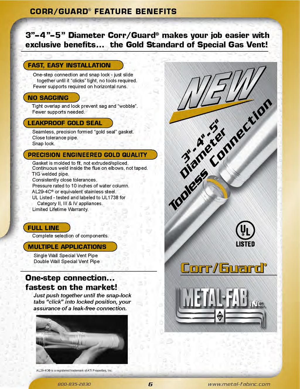
SPECIAL GAS VENT P R E C I S I O N E N G I N E E R E D F O R FA S T I N S TA L L AT I ON E X C L U S I V E S N A P - L O C K D E S I G N
 SPECIL GS VENT P R E C I S I O N E N G I N E E R E D F O R F S T I N S T L L T I ON E X C L U S I V E S N P - L O C K D E S I G N SINGLE WLL DOULE WLL 3, 4 & 5 DIMETER MODEL CGV - VLUE MODEL CG - STNDRD
Saf-T Vent EZ Seal. Technical and Dimensional Data. Single Wall AL 29-4C Stainless Steel Special Gas Vent
 Technical and Dimensional Data Saf-T Vent EZ Seal Single Wall L 29-4 Stainless Steel Special Gas Vent Tested and Listed to UL 1738/UL S636 by Underwriters Laboratories, Inc opyright 2008 Selkirk orp. Saf-T
Saf-T Vent EZ Seal. Technical and Dimensional Data. Single Wall AL 29-4C Stainless Steel Special Gas Vent
 Technical and Dimensional Data Saf-T Vent EZ Seal Single Wall L 29-4 Stainless Steel Special Gas Vent Tested and Listed to UL 1738/UL S636 by Underwriters Laboratories, Inc 5030 orporate Exchange lvd Grand
venting systems for high efficiency appliances series
 venting systems for high efficiency appliances series SUPERIOR SYSTEM DESIGN event DualSeal with RapidLock Connection System is a modular double wall prefabricated vent and exhaust systems used in venting
PRESSURE RATED CHIMNEYS & VENTS
 SELETION GUIDE PRESSURE RTED HIMNEYS & VENTS MODELS PSW PI IPI-1 IPI-2 IPI-4 Single Wall Double Wall Double Wall Double Wall Double Wall 1 ir 1 eramic 2 eramic 4 eramic Insulated Insulation Insulation
Our mission is to become the supplier of choice for gas venting products and solutions.
 Our mission is to become the supplier of choice for gas venting products and solutions. Company Profile Cheminée Lining started out as a sales company that provided customers with quality products and
Saf-T Vent EZ Seal. Technical and Dimensional Data. Single Wall AL 29-4C Stainless Steel Special Gas Vent
 Technical and Dimensional Data Saf-T Vent EZ Seal Single Wall AL 29-4C Stainless Steel Special Gas Vent 130 Industrial Boulevard Turners Falls, MA 01376 Copyright 2001 Heat-fab, Incorporated Saf-T Vent
Technical and Dimensional Data. Double Wall AL 29-4C Stainless Steel Special Gas Vent and Type L Vent
 Technical and Dimensional Data Saf-T Vent I Plus Double Wall L 29-4 Stainless Steel Special Gas Vent and Type L Vent For Venting ommercial & Industrial ppliances ondensing ppliances ategory I,II,III,IV
MODEL PA. Chimney and Exhaust Systems. Underwriters c. Laboratories Inc. LISTED
 MODEL P Chimney and Exhaust Systems UL UL Underwriters c Laboratories Inc. LISTED LISTINGS The Schebler Model P chimney and exhaust system is listed by Underwriters Laboratories Inc. (UL) under file number
MODEL P1. Chimney and Exhaust Systems. Underwriters c. Laboratories Inc. LISTED
 MODEL P1 Chimney and Exhaust Systems UL UL Underwriters c Laboratories Inc. LISTED LISTINGS The Schebler Model P1 chimney and exhaust system is listed by Underwriters Laboratories Inc. (UL) under file
MODEL P4. Chimney and Exhaust Systems. Underwriters c. Laboratories Inc. LISTED
 MODEL P4 Chimney and Exhaust Systems UL UL Underwriters c Laboratories Inc. LISTED LISTINGS The Schebler Model P4 chimney and exhaust system is listed by Underwriters Laboratories Inc. (UL) under file
MODEL P2A. Chimney and Exhaust Systems. Underwriters c. Laboratories Inc. LISTED
 MODEL P2 Chimney and Exhaust Systems UL UL Underwriters c Laboratories Inc. LISTED LISTINGS The Schebler Model P2 chimney and exhaust system is listed by Underwriters Laboratories Inc. (UL) under file
FACTORY-BUILT GREASE DUCT SYSTEMS
 FTORYUILT GRESE DUT SYSTEMS For Kitchen Ventilation Systems DESRIPTION METLF G SERIES Models 3G / 4G Models PI / 1G / 2G Models PSW LTERNTE TO FIRE RESISTIVE SHFT ENLOSURE Factory uilt REDUED LERNE TO
Series. Chimney System for High Efficiency Appliances. Underwriters c. Laboratories Inc. LISTED
 Series Chimney System for High Efficiency ppliances UL UL Underwriters c Laboratories Inc. LISTED LISTINGS The Schebler event and eventplus system are tested and listed by Underwriters Laboratories Inc.
3 through 16 Commercial & Industrial
 3 through 6 ommercial & Industrial Sets the standard yet again as the first L 29-4 Double Wall Vent System with a built-in gasket, a mechanical locking band and featuring a full ½ air space for superior
Technical and Dimensional Data. Double Wall One Inch Air Space AL 29-4C Stainless Steel Special Gas Vent
 Technical and Dimensional Data Saf-T Vent I Plus Double Wall One Inch ir Space L 29-4 Stainless Steel Special Gas Vent For Venting ommercial & Industrial ppliances ondensing ppliances ategory I,II,III,IV
DuraChimney II. Air-cooled chimney system for masonry fireplaces. UL 103.
 DuraChimney II Air-cooled chimney system for masonry fireplaces. UL 103. Specifications Applications DuraChimney II is a double-wall, air-cooled chimney system for use with masonry fireplaces which burn
Technical and Dimensional Data. Double Wall One Inch Air Space 316L Stainless Steel Special Gas Vent
 Technical and Dimensional Data Saf-T Vent I 316 Double Wall One Inch ir Space 316L Stainless Steel Special Gas Vent For Venting ommercial & Industrial ppliances ondensing ppliances ategory I,II,III,IV
Model N. Stainless Steel Double Wall Positive Pressure Venting Systems. Special Gas Vent Applications COMMERCIAL AND INDUSTRIAL VENTING
 COMMERCIL ND INDUSTRIL VENTING Model N Stainless Steel Double Wall Positive Pressure Venting Systems Special Gas Vent pplications Model N is a single wall negative, neutral, or positive pressure pre-fabricated
SELKIRK CORP INSTALLATION INSTRUCTION SUPPLEMENT MODEL G - CHIMNEY LINER
 SELKIRK CORP MODEL G - CHIMNEY LINER These instructions are supplemental to the General Installation Instructions for Selkirk Model G, PS, IPS and ZC Single Wall, Double Wall Air & Fiber Insulated Positive
venting systems for high efficiency appliances series
 venting systems for high efficiency appliances series LISTINGS The Schebler event and event PLUS system are tested and listed by Underwriters Laboratories Inc. (UL) under file number MH10056 for UL 1738
NEW FasNSeal 80/90. FasNSeal & FasNSeal W2. FasNSeal Flex. Exhausts 90+ condensing appliances with Type B atmospheric units within the same vent.
 NEW FasNSeal 80/90 Exhausts 90+ condensing appliances with Type atmospheric units within the same vent. FasNSeal & FasNSeal W2 Single-wall and double-wall special gas vent systems. UL 1738 and UL S636.
Technical and Dimensional Data. Double Wall One Inch Air Space AL 29-4C Stainless Steel Special Gas Vent
 $5 Technical and Dimensional Data Saf-T Vent CI Plus Double Wall One Inch Air Space AL 29-4C Stainless Steel Special Gas Vent For Venting Commercial & Industrial Appliances Condensing Appliances Category
Installation Instructions
 Installation Instructions Models: SLP Venting System These venting system components have been tested for use with approved HHT Direct Vent appliances. Check with your local building code agency before
Modular Double-Wall Positive Pressure Chimney Boiler Breeching & Stack and Engine Exhaust Grease Duct
 Modular Double-Wall Positive Pressure himney oiler reeching & Stack and Engine Exhaust Grease Duct DuraStack Pro Modular Double-Wall Positive Pressure himney oiler reeching & Stack and Engine Exhaust DuraStack
Stovepipe DVL. DuraBlack. Double-wall interior stovepipe for connecting woodstoves to chimney. ULC S641.
 Stovepipe DVL Double-wall interior stovepipe for connecting woodstoves to chimney. UL S641. Duralack Single-wall interior stovepipe for connecting woodstoves to chimney. Specifications DVL pplications
DVL. DuraBlack. Double-wall interior close clearance stovepipe for connecting woodstoves to chimney. ULC S641.
 DVL Double-wall interior close clearance stovepipe for connecting woodstoves to chimney. UL S641. Duralack Single-wall interior stovepipe for connecting woodstoves to chimney. Specifications DVL pplications
MODEL E/V B-VENT CHIMNEY
 MNUFCTURING EXCELLENCE HVC Steel Duct Pipe & Fittings MODEL E/V -VENT CHIMNEY Type Gas Vent 10" 30" ECCO is proud to be a member of: SMCN Sheet Metal and ir Conditioning Contractors National ssociation
INSTALLATION AND MAINTENANCE INSTRUCTIONS
 INSTALLATION AND MAINTENANCE INSTRUCTIONS MODEL IPIC GREASE DUCT AND CHIMNEY IPIC This symbol on the nameplate means this product is listed by Underwriters Laboratories Inc. and by Underwriters Laboratories
INSTALLATION AND MAINTENANCE INSTRUCTIONS
 INSTALLATION AND MAINTENANCE INSTRUCTIONS MODEL PIC/IPIC CHIMNEY AND VENTS PIC IPIC This symbol on the nameplate means this product is listed by Underwriters Laboratories Inc. and by Underwriters Laboratories
Model VSI-I & VSI-II Positive Pressure Venting Systems
 C O M M E R C I A L A N D I N D U S T R I A L V E N T I N G Model VSI-I & VSI-II Positive Pressure Venting Systems Ideal for discharging exhaust gases and fumes from boilers, heaters, ovens, engines, turbines
Specifications. UL 1777 and ULC S641 System. Combustion Air System-DuraTech and DuraPlus HTC
 Combustion ir System Triple-wall stovepipe system designed to provide air for combustion through its components. UL 1777 and ULC S641. DVL Double-wall interior close clearance stovepipe for connecting
Direct or Non-Direct Venting
 Venting Direct or Non-Direct Venting All furnaces are dual certified, and built with a 2 vent/ intake pipe and connectors. Transitioning from 2 to 3 PVC pipe should be done as close to the furnace as possible.
Models PS/IPS. Stainless Steel Double Wall Positive Pressure Piping Systems FEATURES CATALOG
 CATALOG Models PS/IPS Stainless Steel Double Wall Positive Pressure Piping Systems Selkirk Commercial & Industrial Models PS and IPS are modular, prefabricated piping systems which embody flanged joints
Riva Plus HEAT ONLY & COMBI BOILER. Please Read This Guide Carefully and Save for Future Reference
 Condensing Vent Component & Installation Guide Riva Plus HEAT ONLY & COMBI BOILER Please Read This Guide Carefully and Save for Future Reference - This guide is intended to provide detailed information
ELECTRIC SHOCK HAZARD/FIRE AND/OR EXPLOSION HAZARD. ELECTRIC SHOCK HAZARD/FIRE AND/OR EXPLOSION HAZARD.
 INSTALLATION INSTRUCTIONS FOR CONCENTRIC VENT KIT P/N AOPS7483 (for 4 flue roof jack) CONCENTRIC VENT KIT P/N AOPS7544 (for 5 flue roof jack) DUAL PIPE FLASHING KIT P/N AOPS7484 ELECTRIC SHOCK HAZARD/FIRE
Model DW Series Positive Pressure Guidelines for Engine Exhaust Systems
 Model DW Series Positive Pressure Guidelines for Engine Exhaust Systems UL Listed Under: UL 103 / ULC ORD C959 UL 2561 / ULC ORD C959 UL 641 / ULC S609 1 Please note these instructions cover the additional
DVL & DuraBlack. Simpson Dura-Vent Engineered Excellence
 DVL & Duralack Simpson Dura-Vent Engineered Excellence DVL pplications Double-wall interior stovepipe for connecting wood stoves to manufactured chimney. Materials and Construction.016 stainless steel
SIGRAM FLUE SYSTEMS LTD
 SIGRAM FLUE SYSTEMS LTD TEL: 0161 320 1999 FAX: 0161 320 6515 E-MAIL: sales@sigram.co.uk WEB: www.sigram.co.uk FLUE SYSTEMS FOR INDUSTRIAL & COMMERCIAL APPLICATIONS SINCE 1969 PROJECT WORK SITE SURVEY
Gas Venting Systems residential industrial commercial
 Gas Venting Systems residential industrial commercial AirJet Gas Vent AirJet Gas Vent is listed by Underwriters Laboratories, Standard UL-441, and accepted by FHA, VA, BOCA, ICBO and SBCted by Underwriters
Series AIR LINE COMPRESSED AIR DISTRIBUTION SYSTEM
 Series IR LINE COMPRESSED IR DISTRIUTION SYSTEM 26 IR LINE IR DISTRIUTION SYSTEM FETURES ND ENEFITS Installation ease: IR LINE installations can be carried out easily by the end-user, eliminating the need
Model DW Series Positive Pressure Guidelines for Engine Exhaust Systems
 1 Model DW Series Positive Pressure Guidelines for Engine Exhaust Systems UL Listed under Standard 103 for Flue Gas Temperatures up to 1400 F (759 C) Venting System for Factory-Built Chimneys For Building
N2-GEN. TL SERIES Nitrogen Generators. Arc Suppression System. Transmission Line Pressurization. South-Tek
 TL SERIES Nitrogen Generators Transmission Line Pressurization N2-GEN rc Suppression System www.southteksystems.com commercialsales@southteksystems.com 888.526.6284 South-Tek Systems 2 N 2 -GEN rc Suppression
INSTALLATION INSTRUCTIONS FOR BATTERY POWERED SENSOR ACTIVATED HAND WASHING FAUCETS
 ode No. 081633 Rev. (08/10) INSTLLTION INSTRUTIONS FOR TTERY POWERED SENSOR TIVTED HND WSHING FUETS Model EF-550-S-H Wall Mounted, attery Powered, Sensor ctivated, Gooseneck Hand Washing Faucet With Surgical
INSTALLATION INSTRUCTIONS FOR BATTERY POWERED SENSOR ACTIVATED HAND WASHING FAUCETS
 ode No. 081633 Rev. 1 (1/08) INSTLLTION INSTRUTIONS FOR TTERY POWERED SENSOR TIVTED HND WSHING FUETS Model EF-550-S-H Wall Mounted, attery Powered, Sensor ctivated, Gooseneck Hand Washing Faucet With Surgical
All-Fuel Chimney Systems
 U.S. TECHNICAL DOCUMENTS Example: Fireplace Opening 42 W by H Chimney Height 12 Use 14 Diameter 36 42 4 FIREPLACE OPENING HEIGHT, in.,h The Selkirk All-Fuel 24 Chimney system includes a variety of components
SINGLE WALL AL 29-4C SPECIAL GAS VENT
 Straight Lengths: Saf-T Vent EZ Seal SINGLE WLL L 29-4 SPEIL GS VENT 6" Length Install vent with a continuous pitch of 1/4 per foot, sloping upward toward the termination, draining back Part Number DIM
Model RIS ALL FUEL, INSULATED CHIMNEY SYSTEM 10" - 24"
 ALL FUEL, INSULATED CHIMNEY SYSTEM 10" - 24" 42 Technical Information Technical Information Certification is tested and listed by Intertek Testing Services to the following standard: UL 103HT - The standard
Installation Instructions
 Installation Instructions Models: Cinch Pipe & Termination Cap System See the installation instructions included with the appliance for configuration of vent assembly and clearances to pipe. If you need
TYPE B GAS VENT SYSTEMS
 TYPE GS VENT SYSTEMS SIMPSON DUR-VENT For 33 years, the Dura-Vent ompany has been a leading manufacturer of Gas Vent and himney Products. In 1982, Dura-Vent joined the Simpson family of companies... famous
Table of Contents WARRANTY...3 APPLICATION...4 MECHANICAL...5 Joint Sealant...5 Grease Duct Standard Connection...6 Collar and Adjustable Duct
 Non-Welded Grease Duct Systems Installation, Operation, and Maintenance Manual FOR YOUR SAFETY TWO MAJOR CAUSES OF GREASE DUCT RELATED FIRES: () FAILURE TO MAINTAIN REQUIRED CLEARANCE (AIR SPACE) TO COMBUSTIBLE
SITELINE WOOD WINDOW GEOMETRIC / DIRECT SET TABLE OF CONTENTS
 GEOMETRI / DIRET SET TLE OF ONTENTS rchitectural Design Manual Questions? onsult JELD-WEN customer service. 1 GEOMETRI / DIRET SET GENERL INFORMTION Standard Sizes & Designs Wood geometric windows are
Vertical Balanced Flue Kit All Internal Grant Boilers
 GENERAL Flue sections cannot be cut. Part No. DOC30 REV04 October 2008 SUPPLEMENTARY INSTALLATION INSTRUCTIONS Vertical Balanced Flue Kit All Internal Grant Boilers THIS SUPPLEMENT SHOULD BE READ IN CONJUNCTION
Versatility in Applications
 Versatility in Applications For over 60 years, Van-Packer has been supplying the Commercial and Industrial market with venting products. From our Model DW (Double Wall Stainless Steel) to Refractory Lined,
EXHAUST. Accessory Catalog and Specifications. Silex INNOVATIONS NGP032
 EXHUST ccessory atalog and Specifications Silex INNOVTIONS NGP032 PSSIONTE OLLORTIVE INNOVTIVE TRUSTED EMPOWERED ENERGIZED World Headquarters 1560 Williams Drive Stoughton Wisconsin Stoughton, WI 53589
RECEIVING AND INSPECTION EXAMINE ALL COMPONENTS FOR POSSIBLE SHIPPING DAMAGE PRIOR TO INSTALLATION.
 Non-Welded Grease Duct Systems Installation, Operation, and Maintenance Manual FOR YOUR SAFETY TWO MAJOR CAUSES OF GREASE DUCT RELATED FIRES: (1) FAILURE TO MAINTAIN REQUIRED CLEARANCE (AIR SPACE) TO COMBUSTIBLE
MODELS LCE/LCS, L2E/L2S, L3E/L3S
 ELT DRIVE SIDEWLL PROPELLER FNS LINE OVERVIEW Jenco s elt Drive Sidewall Propeller line is designed to exhaust or supply large volumes of air at relatively low static pressures. With 3 levels of construction,
RECTANGULAR, 2-HOUR FIRE RATED, ZERO-CLEARANCE GREASE DUCT CO.
 RECTANGULAR, 2-HOUR FIRE RATED, ZERO-CLEARANCE GREASE DUCT CO. For over 75 years, Van-Packer has supplied venting products to the Commercial and Industrial heating and process markets. For the past 30
ANSUL. Vertical and Horizontal Bladder Tanks
 NSUL SYSTEM OMPONENTS U.S..G. PPROVL NO. 162.033/14/0 REV. 0 UL EX-3933 7-1-94 Page 2-59 Vertical and Horizontal ladder Tanks PPLITION The nsul bladder tank is one component in a balanced pressure proportioning
HIGH CAPACITY POWER VENT KIT
 IMPORTANT: THESE INSTRUCTIONS ARE TO REMAIN WITH THE APPLIANCE INSTRUCTIONS These instructions are supplementary to the Installation and Operating Instructions supplied with the fi replace and should be
FasNSeal & FasNSeal W2. FasNSeal Flex. Single-wall and double-wall special gas vent systems. UL 1738 and ULC S636.
 FasNSeal & FasNSeal W2 Single-wall and double-wall special gas vent systems. UL 1738 and ULC S636. FasNSeal Flex Flexible chimney liner for special gas vent system. UL 1738 and UL 1777. Specifications
RECEIVING AND INSPECTION
 Non-Welded Grease Duct Systems Installation, Operation, and Maintenance Manual FOR YOUR SAFETY TWO MAJOR CAUSES OF GREASE DUCT RELATED FIRES: (1) FAILURE TO MAINTAIN REQUIRED CLEARANCE (AIR SPACE) TO COMBUSTIBLE
Large Diameter Chimney System
 CATALOG Large Diameter Chimney System The Selkirk Large Diameter Chimney is a perfect fit for large custom masonry fireplaces. Selkirk offers the best selection of large diameter chimney pipe in the industry:
Ventinox kits. Ventinox VFT Kit without Tee. Ventinox VFT Kit with Tee. Ventinox VFT Extensions. Flexible Relining Ventinox
 Flexible Relining Ventinox Ventinox kits Ventinox Kit without Tee Includes Ventinox Liner, Top Plate, and Rain Cap with Storm Collar. Choose diameter and length needed. SIZE LENGTH 3 25-3K25 316013 4 25-4K25
VENTING & COMBUSTION AIR GUIDE
 PRE-INSTALLATION APPLICATION GUIDE VENTING & COMBUSTION AIR GUIDE Natural Gas, Propane and Dual Fuel Modulating and Condensing BOILER BODY VENT STARTER SECTION APPLIES TO MODELS: BMK 750 BMK 1000 BMK 1500
Product Catalog and Dimensional Data
 Product atalog and Dimensional Data Spring 2019 FIRST LISTED InnoFlue is the first polymeric vent system tested and listed to UL-S636 and UL-1738 in North merica http://centrotherm.us.com 518.434.3400
High-Flow Stainless Tubes. Standard Tubes BRASS 18 LONG STAINLESS STEEL 18 LONG H11. All stainless construction for high strength and durability
 High-Flow Stainless Tubes H11 ll stainless construction for high strength and durability Use with all PCS cascades J in part number indicates next largest thread TUE TUE L = 12 18 24 36 HF093T-.090.076
Flue installation instructions. Air flue duct for use with ecomax and ecotec boilers. For the installer
 834449_05GB_022005.qd 02.02.2005 17:12 Uhr Seite 1 For the installer Flue installation instructions Air flue duct for use with ecomax and ecotec boilers ecomax 613/2 E ecomax 618/2 E ecomax 622/2 E ecomax
Installation Instructions
 Installation Instructions Models: Cinch Pipe & Termination Cap System See the installation instructions included with the appliance for configuration of vent assembly and clearances to pipe. If you need
InoxSabiana 50 Flues Stainless Steel Double Wall ENVIRONMENTAL COMFORT
 Flues Stainless Steel Double Wall ISO 9001 - Cert. n 0545/4 Unit heaters Radiant panels Fan coils Air handling units Flues ENVIRONMENTAL COMFORT Introduction and main constructional characteristics Double
STAINLESS STEEL FITTINGS
 nvilpress Stainless Steel Fittings provide a complete line of mechanically joined press-fittings in sizes 1 /2 through 2 inches. These fittings are designed to work with Schedule 5 or 10 Stainless Steel
! WARNING: FIRE OR EXPLOSION HAZARD
 Form I-SSL/RPL (Version E.3) Obsoletes I-SSL/RPL (Version E.2) INSTALLATION / OPERATION / MAINTENANE Applies to: Model SSL and Model RPL Packaged Systems USTOMER AGENY PRODUT PROESS QS ONVERGENT QUALITY
SECTION CENTRIFUGAL HVAC FANS
 SECTION 233416 - CENTRIFUGAL HVAC FANS 1. PART 1 GENERAL 1.1. RELATED DOCUMENTS A. Drawings and general provisions of the Contract, including General and Supplementary Conditions and Division 01 Specification
Stovepipe DVL. DuraBlack. Double-wall interior stovepipe for connecting woodstoves to chimney. ULC S641.
 Stovepipe DVL Double-wall interior stovepipe for connecting woodstoves to chimney. ULC S641. Duralack Single-wall interior stovepipe for connecting woodstoves to chimney. Specifications DVL Applications
SECTION AXIAL HVAC FANS
 SECTION 233413 - AXIAL HVAC FANS 1. PART 1 GENERAL 1.1. RELATED DOCUMENTS A. Drawings and general provisions of the Contract, including General and Supplementary Conditions and Division 01 Specification
SINGLE DUCT TERMINAL UNITS 30X/HQX SERIES
 30X/HQX SERIES 30X SERIES EXHUST 30HQX SERIES EXHUST HOSPITL GRDE QUIET TYPE WITH DISSIPTIVE SILENCER PRODUCT OVERVIEW Nailor Single Duct Exhaust Terminal Units are used to modulate exhaust flow from an
MODELS GED/GSD, DFE/DFS, DDE/DDS DIRECT DRIVE SIDEWALL PROPELLER FANS WALL HOUSING MOUNTING OPTIONS WALL HOUSING
 DIRECT DRIVE SIDEWLL PROPELLER FNS WLL HOUSING MOUNTING OPTIONS WLL HOUSING: This heavy-gauge, all galvanized G-90 steel (aluminum optional) housing provides a simple solution to installing a fan and all
Appendix E D791 and T791 Head and Valve Holddown Assembly Details
 Appendix E D nd T Hed nd Vlve Holddown Assemly Detils Hed First Stge Holddown Assemly (") Suction with Unloder Suction (Stndrd) First Stge Holddown Assemly (") Dischrge See figure A 0 CAUTION: Alwys relieve
Ø5/16" HOLES FOR FASTENING TO CURB
 SIDE INTKE SUPPLY UNIT / SIDE INTKE GLVNIZED SUPPLY UNIT OPERTION INSTRUCTIONS ND PRTS MNUL SIS SERIES MODELS: SIS-9, SIS-10, SIS-12, SIS-15, SIS-18, SIS-20 SIG SERIES MODEL: SIG-9, SIG-10, SIG-12, SIG-15
MODELS GED/GSD, eged/egsd, DFE/DFS, DDE/DDS
 LINE OVERVIEW Jenco s Direct Drive Sidewall Propeller line is designed to exhaust or supply large volumes of air at relatively low static pressures. With 3 types of construction, the direct drive models
Thermocouple & RTD Accessories (Thermowells, Connectors & Fittings)
") Thermocouple & RTD ccessories (Thermowells, onnectors & Fittings) TLE OF ONTENTS ESSORIES FOR THERMOOUPLE & RTD s MODEL DESRIPTION PGE P SERIES THERMOWELLS 96 X1 THERMOOUPLE EXTENSION LES 97 X2 RTD EXTENSION
Thermocouple & RTD ccessories (Thermowells, onnectors & Fittings) TLE OF ONTENTS ESSORIES FOR THERMOOUPLE & RTD s MODEL DESRIPTION PGE P SERIES THERMOWELLS 96 X1 THERMOOUPLE EXTENSION LES 97 X2 RTD EXTENSION
SECTION HVAC POWER VENTILATORS
 SECTION 233423 HVAC POWER VENTILATORS 1. PART 1 GENERAL 1.1. RELATED DOCUMENTS A. Drawings and general provisions of the Contract, including General and Supplementary Conditions and Division 01 Specification
Summary 0163EN. Chapter 5 - Couplings A70 Double Jacket Brass Coupling A70 Single Jacket Brass Coupling 37 A71 Forestry Coupling 37
 pril 2008 0163EN Summry Fire protetion produts hpter 1 - Hose, Sprinkler Vlves nd essories 53 Gte Vlve 300 l. Rted 4 53G Single Hydrnt Gte Vlve 4 50 ngle Hose Vlve with Hydroltor 5 51 ngle Hose Vlve with
FE-1000 INSERTION TYPE AIRFLOW SENSING ELEMENT
 Technical Data Sheet FE-1000 INSERTION TYPE IR SENSING ELEMENT DESCRIPTION The FE-1000 is an insertion type airflow sensing element designed for quick, easy installation through a small cutout in the existing
Nor-Cal Products. where technology takes shape. vacuum products catalog
 Nor-al Products where technology takes shape vacuum products catalog s & Fittings Section Two.0 s & Fittings General Information 8. NW s & Fittings 9. ISO s & Fittings 9.3 S s & Fittings 38.4 F s & Fittings
Viking Installation Guide
 iking Installation Guide iking Range orporation Front Street Greenwood, Mississippi 890 US (66) 455-00 For product information, call -888-IKING (845-464) or visit the iking Web site at vikingrange.com
CB29M. Multi Position 60 HZ A I R H A N D L E R S. 3 to 5 Tons Optional Electric Heat 5 to 30 kw CB 29 M 41 1 E N G I N E E R I N G D A T A
 E N G I N E E R I N G D T I R H N D L E R S CB29M Multi Position 60 HZ Bulletin No. 210478 November 2008 Supersedes July 2007 3 to 5 Tons Optional Electric Heat 5 to 30 kw MODEL NUMBER IDENTIFICTION CB
MODEL COMPARISON MOUNTING ARRANGEMENT OPTIONS
 LINE OVERVIEW S&P s Direct Drive Sidewall Propeller Fan line is designed to exhaust or supply large volumes of air at relatively low static pressures. With 3 types of construction, the direct drive models
O-RING SEAL TUBE FITTINGS
 Hose Fittings O-RING SEL TUBE FITTINGS TLOG NO. LORS-16 i Phone: 937/277-9364 FX: 937/277-6516 www.lenzinc.com Hose O-RING Fittings SEL The goal of Lenz is to help our Distributors, OEM s and customers
PRE-INSTALLATION VENTING AND COMBUSTION AIR DESIGN GUIDE
 Benchmark Series GF-2050 PRE-INSTALLATION VENTING AND COMBUSTION AIR DESIGN GUIDE Natural Gas, Propane Gas, or Dual Fuel Fired Modulating, Condensing BENCHMARK & Benchmark Platinum Gas-Fired This document
(Standard) (Heavy Duty) (Heavy Duty w/ (Guillotine) (Flat Strap U-Bolt) Welded Saddle)
 (Heavy Duty) (Heavy Duty w/ (Guillotine) (Flat Strap U-Bolt) Welded Saddle)") ESSORIES LMPS (50) (50) (50) (50) Size Indiv. ulk (50) (50) Indiv. Indiv. Indiv. Indiv. Indiv. Pkg. Pkg. Indiv. Pkg. ulk Pkg. Part Part Part Part Part 1¹/₈ 35322 1¹/₄ 35323 1³/₈ 35324 1¹/₂ 35325 34112
ESSORIES LMPS (50) (50) (50) (50) Size Indiv. ulk (50) (50) Indiv. Indiv. Indiv. Indiv. Indiv. Pkg. Pkg. Indiv. Pkg. ulk Pkg. Part Part Part Part Part 1¹/₈ 35322 1¹/₄ 35323 1³/₈ 35324 1¹/₂ 35325 34112
Model B. Thermostatic Valves FEATURES APPLICATIONS FLOW RATES OF USGPM TAMPER-PROOF TEMPERATURE SETTINGS OF 55 F F
 Model Thermostatic Valves FETURES FLOW RTES OF 68-1200 USGPM TMPER-PROOF TEMPERTURE SETTINGS OF 55 F - 240 F OMPLETELY SELF-ONTINED POSITIVE 3-WY VLVE TION VILLE IN ST IRON, DUTILE IRON, RONZE, STEEL,
Installation, Operation and Maintenance Manual
 Document 481038 Model PVF and PVG Indirect Gas-Fired Heat Modules Indirect Gas-Fired Furnaces Installation, Operation and Maintenance Manual Please read and save these instructions for future reference.
OPTIONAL VERTICAL OR HORIZONTAL POWER VENT KIT
 IMPORTANT: THESE INSTRUCTIONS ARE TO REMAIN WITH THE HOMEOWNER These instructions are supplementary to the Installation and Operating Instructions supplied with the fireplace and should be kept together.
Priming Systems Installation Instructions
 Priming Systems Installation Instructions System Components: Single Priming Pump: Single VAP Valve Systems: Control Panel Activated... 2 Auto Prime (Pressure Switch) Activated... 3 Multiple VAP Valve Systems...
DMC-500 TM. DC Motor Drive Control. Operation / Installation Manual Manual Part Number: S8M5003 Date: August 11, Computer Weld Technology, Inc.
 omputer Weld Technology, Inc. 070 Old ammel N Houston Rd. Houston, TX 77086 Telephone: (7) 46-8 Fax: (7) 46-50 DM-500 TM D Motor Drive ontrol Operation / Installation Manual Manual Part Number: S8M500
Installation, Operation and Maintenance Manual
 Document 481038 Model PVF(-H) and PVG Indirect Gas-Fired Heat Modules Indirect Gas-Fired Furnaces Installation, Operation and Maintenance Manual Please read and save these instructions for future reference.