Versatility in Applications
|
|
|
- Sibyl Nicholson
- 5 years ago
- Views:
Transcription

1


2
3 Versatility in Applications For over 60 years, Van-Packer has been supplying the Commercial and Industrial market with venting products. From our Model DW (Double Wall Stainless Steel) to Refractory Lined, to Free Standing Engineered Chimneys, Van-Packer is the only one-stop shopping company that offers a product to fit your exact requirements. UNDERWRITERS LABORATORIES LISTING Van-Packer Model DW series products are Listed by UL (under file number MH 11435, UL 103) as a 1400 Fahrenheit Chimney for continuous operation at 1400 F (760 C) and intermittent operation at 1800 F (983 C). The Model DW series is also suitable for use as a Building Heating Appliance Chimney for continuous operation at 1000 F (538 C) and intermittent operation at 1400 F (760 C). For Grease Laden Vapors (UL 1978) 500ºF (260ºC) continuous to 2000ºF (1093ºC) intermittent operation. PROFESSIONAL ENGINEERING AND TECHNICAL SUPPORT Van-Packer welcomes the opportunity to assist you with your design or will design a system that provides you maximum performance and longevity. From sizing calculations to a fully designed exhaust system, our staff will provide you with: a Designed System, Chimney Sizing, Thermal Analysis, Corrosion Analysis, complete Bill-of-Materials and Free CAD drawings. Van-Packer is the only company who can meet your exact specifications! MODEL DW AND DWplus The most versatile product offered in the industry, with tees, elbows, supports, guying and transitions, nothing is left for field fabrication. Inside diameters of 6" through 36" come standard with 20-gauge type 304 stainless steel inner liners. Inside diameters of 38" through 48" come standard with 18-gauge type 304 stainless steel inner liners. Outside diameters of 8" through 26" come standard with 24-gauge aluminized steel and sizes 28" through 56", 20-gauge aluminized steel outer shells. Optional materials such as 316 stainless steel for inner liner and outer shell as well as other materials and gauges are available upon request. Model DW is standard with 1" air space between the liner and shell. Optional material insulation of 1", 2", 3" or 4" thickness is available for Model DWplus. Standard sizes of 6"-48" diameters, other diameters available upon request Materials are shipped fully enclosed until needed and palletized for ease of on-site handling 10-year Factory Warranty available Quick Factory Delivery Factory Trained Representatives Toll-Free consultation and assistance VPSTACK ( ) ENCLOSURES The Model DW Series Chimney is intended to be installed unenclosed or within non-combustible enclosures. The Model DW Series Chimney is not for use in one or two-family residences. CAUTION Do not enclose the Model DW Series Chimney in a passageway or chase constructed of combustible material such as wood. When the chimney extends through any zone or story above that on which the connected appliance is located, it is to be provided with an enclosure having a fire resistance rating equal to or greater than that of the floor or roof assemblies through which it passes. (NOTE Always check with local building code authorities having jurisdiction for material with appropriate fire resistance rating.) If a portion of the Model DW series chimney is placed between a dropped ceiling and roof, that portion should be enclosed in an appropriate fire rated enclosure. The Model DW series is NOT intended to pass through a combustible wall, but any wall, which the chimney passes through, must be of non-combustible construction. 1
4 TERMINATION HEIGHT ABOVE ROOF All vents shall terminate above the roof surface through the roof flashing no lower than three feet. The height of a chimney above the roof through which it passes and any surrounding equipment should be determined based on the appliance type. See NFPA 211 for appliance categories and their requirements. Consideration should also be given to local building codes, fire codes, and air pollution regulations. The appliance manufacturer s recommendations for minimum heights for the operating draft needs of that particular appliance must also be taken into account. CLEARANCES Model DW 1400 F (760 C) 1000 F (538 C) Combustible All Sizes 6" (152mm) 4" (102mm) Non-Combustible 18"ID or Less 2" (51mm) 2" (51mm) Non-Combustible Over 18"ID 4" (102mm) 4" (102mm) Model DWplus Series Combustible All Sizes 4" (102mm) 2" (51mm) Non-Combustible 18"ID or Less 2" (51mm) 2" (51mm) Non-Combustible Over 18"ID 4" (102mm) 2" (51mm) NOTE: Clearance in a non-combustible interior chase shall be as necessary for installation or access. GREASE DUCT CLEARANCE CHART Model DW DWplus & plus2 DWplus3 DWplus4 Section ID (Inches) (Inches, mm) (Inches, mm) (Inches, mm) (Inches, mm) 6 7 / / / / / / / / / / / / / / / / / / / / / / / / / / / / / / / / / / / / / / / / / / / / / / / / / / / / / / / / / / / / / / / / / / / / / / / / / / / / / / / / / / / / / / / / 457 2
5 MODEL DW/DWplus PARTS IDENTIFICATION All part numbers have a D prefix for Model DW. All part numbers have a + (+2, +3, +4) prefix for the Model DWplus, followed by the section ID, part description, liner/shell designation and a special qualifier code. The qualifier code is used to denote section length on straight sections, projection ID on tee sections and the larger ID on increasers. The part number for a Model DW 8"ID straight section with type 304 stainless steel liner and aluminized steel shell 18 inches long is: STEEL SHELL / LINER D08STRA18 D = Model DW Code 08 = Section ID STR = Part Code A = Shell/Liner Code 18 = Qualifier Code CODE A B C D E F DESCRIPTION Type 304 SS liner w / aluminized shell Type 316 SS liner w / aluminized shell Type 316 SS liner with type 316SS shell Type 304 SS liner with type 304SS shell Type 316 SS liner with type 304SS shell Type 304 SS liner with type 316SS shell LIMITATIONS Offered as guidelines only. Please refer to installation instruction sheets, or ask your area representative or Van-Packer technical services for further details. MODEL DW SERIES LIMITATIONS Maximum height above top lateral brace/guy: 6"ID 12"ID: 10 feet 14"ID 48"ID: 15 feet Maximum space between lateral brace/guy equals 30 feet. Maximum height above the following named components is based upon the chimney diameters; Straight Sections, Tee Sections, and Plate Support Assemblies (see following page). Maximum spacing between breaching supports: 6"ID - 12"ID: 10 feet 14"ID - 48"ID: 15 feet The Adjustable Expansion Section (ADJ) and the Variable Length Section (VLS) are non-load bearing. Adjustable Expansion Sections and Variable Length Sections may require field cutting for proper fit. APPLICATIONS For venting boilers, kilns, incinerators, grease ducts, emergency generators, caustic air, and fumes. FUEL TYPES LP gas, #2, #4, #5, or #6 fuel oils*, wood*, coal*, grease vapors, caustic fumes, and particles. (*It is recommended that 316 stainless steel liner be specified when using these types of fuels.) EXHAUST PRESSURE Neutral, negative, or positive. INSTALLATION RECOMMENDATION One prime coat and one finish coat of paint is recommended on exterior installations when outer shells are constructed of aluminized steel. Approximate Weight Per Foot (lbs) ID DW DW+ DW+2 DW+3 DW+4 6" " " " " " " " " " " " " " " " " " " " " "
, and the Tee Section (90T).")


6 The following chart shows the allowable lengths supported by the Wall Support Assembly (WSA), Wall Flange Assembly (WFA), Plate Support Assembly (PLS), Straight Section (STR), Ventilated Roof Support (VRS), and the Tee Section (90T). ALLOWABLE HEIGHT (Feet) Model DW Model DWplus Model DWplus2 Inside Diameter WSA WFA PLS VRS STR 90T WSA WFA PLS VRS STR 90T WSA WFA PLS VRS STR 90T WSA 6" " " " " " " " " " " " " " " " " " " " " "


7 Model DWplus3 Model DWplus4 ENGINEERING DATA the 350 and 500 temperatures were calculated with 17 fps flue gas velocity the 1000 and 1400 temperatures were calculated with 25 fps flue gas velocity all were calculated with 70 F ambient and 5 fps air velocity Comparative Surface Temperatures Flue Temperature F ID MODEL WFA PLS VRS STR 90T WSA WFA PLS VRS STR 90T Surface Temperature F 6" DW DW DW DW DW " DW DW DW DW DW " DW DW DW DW DW " DW DW DW DW DW " DW DW DW DW DW " DW DW DW DW DW " DW DW DW DW DW


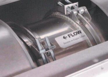
8 Fast, on site assembly, no need for welding or special tools! Components are joined together with a vee band, which is fitted over the flanges of the adjoining inner liner and bolted in place. A draw band is then fitted over the outer shell. Supports and other accessories are just as easy to install. No welding or special tools are ever required. SEALANT illustration 1 1. Apply a continuous bead of the proper sealant to one of the flanges to be joined. illustration 2 2. Join the two flanged ends of the pipe sections together. SEALANT illustration 3 3. Fill the groove of the vee band with the proper sealant for positive pressure applications. 6


9 illustration 4 4. Install vee band around flanges. On large diameters it may be necessary to tap the band while tightening; this will ensure a snug fit. illustration 5 5. Install insulation strips to ensure all air gaps are filled, if installing Model DWplus. illustration 6 6. Secure the outer shell with the draw band. It is recommended that silicone sealant be applied around the top of the draw band to prevent moisture from entering between the chimney walls. This should be done on all components exposed to the atmosphere. A special heat resistant sealant must be used when assembling. Van-Packer s Sealant Part #101087A is used for flue temperatures up to 600 F. Sealant Part #101091F is to be used when temperatures exceed 600 F. 7
10 Adjustable Expansion Section Part ADJ Use the Adjustable Expansion Section for thermal expansion. Part includes: 3/8" hi-temp packing rope, vee band, slip liner, and a cover band. Length adjusts from 1 1/2" to 19 1/2" and may require field trimming. The Model DWplus Series includes a wide strip of insulation. ID 18": K =.40 L/D ID > 18": K =.30 L/D Flow resistance factor for diesel/turbine exhausts and grease ducts: K =.25 L/D L = pipe length in feet D = pipe diameter in inches Variable Length Section Part VLS The VLS used for custom length sections. Length ranges from 4 1/2" to 19 1/2". Part includes: locking collar, vee band, slip liner, and cover band. Model DWplus Series includes a wide strip of insulation. SEALANT ID 18": K =.40 L/D ID > 18": K =.30 L/D Flow resistance factor for diesel/turbine exhausts and grease ducts: K =.25 L/D L = pipe length in feet D = pipe diameter in inches Floor Guide Assembly Part FGA Use the Floor Guide Assembly when penetrating floors. The floor guide rests on the floor and the struts that attach to the lateral support are lagged into the framing around the chimney vent. Fasteners supplied by installer. Part includes: two struts and one split full angle ring, with nuts and bolts. 8
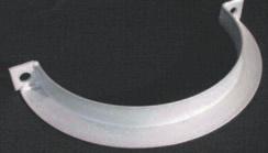
11 Full Angle Ring Part FAR The FAR supports horizontal and lateral lengths of pipe in all diameters, models, and exhaust types. Part includes: one 2-piece angle ring, 1/2 inch nuts and bolts. Half Angle Ring Part HAR The HAR supports horizontal lengths of pipe 24"ID and under. Use on Models DWplus2, 3, and 4. Not for use on engine exhaust systems. Part includes: one half angle ring. Breaching Hanger Band Part BHB The BHB supports horizontal lengths of pipe 24"ID and under. For Models DW and DWplus; not for use on engine exhaust systems. Part includes: one hanger band. Plate Support Assembly Part PLS The PLS consists of one square 2-piece support plate (S/P), one round 2-piece clamp flange (C/F), two half draw bands, 3/8 inch bolts and nuts. The PLS in conjunction with field fabricated support members provides support for the chimney. Wall Support Assembly Part WSA Use the WSA to support vertical lengths of chimney along a wall or chase. The Wall Support Assembly consists of: left and right wall bracket, 2-piece bottom support plate, 2-piece top support plate, 3/8 inch bolts and nuts and two half draw bands. 1/2 inch anchor bolts by installer. 9

12 Wall Guide Assembly Part WGA Used for lateral support, the Wall Guide Assembly attaches to a wall or chase. The Wall Guide Assembly consists of: left and right wall brackets, two half angle rings, 1/2 inch bolts and nuts. 1/2 inch anchor bolts by installer. 6" Wall Flange Assembly Part WFA Use the WFA to support vertical lengths of chimney along a wall or chase. The Wall Flange Assembly consists of: left and right wall brackets, flange assembly, vee band, draw band, bolts and nuts. 1/2 inch anchor bolts by installer. Ventilated Roof Penetration Assembly Part RPA The Ventilated Roof Thimble (part VRT) used in conjunction with the flashing (part FLS) and the counter flashing (part CFL) for passage through a combustible roof structure. These three components are used for a standard flat roof penetration. 10
13 Ventilated Roof Support Assembly Part VRS The Ventilated Thimble (part VRT) used in conjunction with the flange support assembly (FSA), flashing (part FLS), and the counter flashing (part CFL) for passage through a combustible roof structure. Use these four components for a standard flat roof support assembly. Insulated Roof Thimble Part THM Use the Insulated Roof Thimble on Model DW and DWplus Series components. 2-Piece Insulated Roof Thimble Part THM-2PC Use the 2-Piece Insulated Roof Thimble when complications arise, such as the chimney already exists. Thimble is 24" long. Roof opening equals 8 1/2" plus chimney outside diameter. 11
14 Ventilated Roof Thimble Part VRT Use the Ventilated Roof Thimble for Model DW and DWplus Series components. Standard is 20-gauge aluminized. Heat Shield Part HTS Use the Heat Shield on Model DWplus Series components for 1000 F Building Heating Appliance Chimneys only. Roof opening equals chimney OD plus 4-1/2". Counter Flashing Part CFL A counter flashing is installed above the flashing to provide rain protection. Sealant should be applied to prevent leakage. Standard is 24-gauge aluminized, stainless steel optional. Flashing Part FLS Use when the exhaust system is penetrating a roof structure. 24-gauge aluminized steel is standard; stainless steel is optional. 12
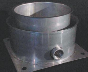
15 Open Top Closure Part OTC The OTC is for vertical terminations. The open top closure closes the gap between the liner and the shell providing a weatherproof seal. Part includes: open top closure, nuts and bolts. Flip Top Cap Part FTCB The FTCB is used to prevent rain from entering generator exhaust pipe. Opens with internal pressure. Part includes: counter balanced flip-top cap, vee band and rain skirt. Rain Skirt Part RSK This component closes off the gap between the liner and shell, protecting the air gap or insulation from the outdoor elements. Part includes: rain skirt, nuts and bolts. 6" Long Base Drain Section Part BDS Use this component on vertical chimney installations when supports are not feasible. The BDS permits drainage of rain and or condensation. Completely closes off base of stack. Supplied with a 1 inch NPT coupling. Allowable height is equal to a straight section (Part: STR). 1/2 inch anchor bolts by installer. In-Line Drain Section Part D/S Used in instances where rain or condensate removal is critical. The In-Line Drain Section should be located below the roofline, preferably as close to the appliance as possible, to prevent freezing. Part includes: in-line drain, vee band and draw band. K =.25 13
16 Velocity Cone Part CON This component is used to increase velocity of exiting flue gases. Part includes: velocity cone, vee band and rain skirt. K = 1.25 Low Loss Rain Cap Part LLR Used for vertical flue terminations. The length of the upper cap is related to rain protection. Rain enters top of cap, runs along inside of jacket and exits at the bottom of the jacket releasing it back into the atmosphere. Part includes: low loss section, vee band and rain skirt. Velocity Cone Chart (Inches) Section ID A B 6 4 1/2 7 1/ /2 7 1/ / / /2 7 1/ / /2 7 1/ / / /2 8 3/ /4 8 7/ /2 10 1/ /2 10 1/ / /2 12 1/ /2 12 1/ / /4 14 1/ / /2 15 7/ /4 16 3/8 Low Loss Rain Cap (Inches) Section ID A B C Engine Exhaust Side Discharge Part ESD Used to horizontally terminate engine/turbine exhaust systems. Part includes: side discharge section, vee band and rain skirt. This component is available with a bird screen upon request. Part number for a bird screen is SDS. Flow resistance factor is same as pipe. 14
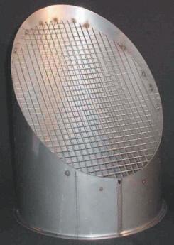
17 Double Cone Rain Cap Part DCR The DCR is for vertical terminations. The Double Cone Rain Cap comes with or without a screen. The part number for a rain cap with screen is RCS. Part includes: double cone rain cap, vee band and rain skirt. Flange Adapter Kit Part FAKB Use the FAKB when the appliance has a 125# drilling (bolt hole pattern). Bolts and nuts supplied by installer. Part includes: 3/8 inch thick van-stone type flange with a starter section. K =.50 Double Cone Rain Cap Chart (Inches) Section ID A B / / / / / / / / / / / / / / / / / / / / / /16 Flange Adapter Chart (Inches) Section Flange Bolt Bolt Holes ID OD Circle Qty Dia /2 8 7/ /2 11 3/4 8 7/ / / / /2 21 1/ / / / / / /2 27 1/ / / / /4 31 3/ / / / / / /4 38 1/ / /4 40 1/ / / / /4 45 1/ / /4 47 1/ / / / /4 51 3/ / /4 53 3/ / / /8 15
18 Boiler Adapter Flange Part BAFA Use the BAFA when the appliance has a blank flanged outlet. Part includes: one 2-piece ring and C clamps. Flangeless Outlet Adapter Part FOAB-1 Use the FOAB-1 on appliance collars without a flange. Part includes: flangeless outlet adapter, vee band and draw band. Transitional Outlet Adapter Part TOA Use as a transition between the appliance outlet and the vent pipe. Part includes: transitional adapter, vee band and draw band. Available in sizes 3" to 6", 4" to 6", 5" to 6", 7" to 8" and 9" to 10". DW Lifting Device Part L/D This device is designed to lift flue in a vertical position only and is not intended to lift flue from a horizontal position (see installation instructions). The following heights are not to be exceeded. Note: this is not a UL listed component. Model DW DW = 67 feet maximum DWplus = 58 feet maximum DWplus2 = 48 feet maximum DWplus3 = 39 feet maximum DWplus4 = 33 feet maximum Model SW SW = 180 feet maximum Model ES ES = 22 feet maximum 16
19 Abrupt Transition Part ATS The ATS is a 3 inch long component designed for changes in diameters. The component consists of a liner, shell, and a small vee band. The ATS does not provide any type of load bearing support. The ATS must always be isolated from loads. Do this by installing a support next to the ATS. Wall Penetration Assembly Part WPA Use on interior walls for added insulation protection. Parts include: Model DWplus2 30" long straight section, two interior plates, vee bands, draw bands, two CVRs, and a wall sleeve. This is a non-ul listed component. Straight Section Part STR Straight section features flanges for ease of installation in both vertical and horizontal runs. Part includes: one 18", 30", or 42" length* section, vee band and draw band. Available in sizes 6" through 48"ID. ID 18": K =.40 L/D ID > 18": K =.30 L/D Flow resistance factor for diesel/turbine exhausts and grease ducts: K =.25 L/D * 42" length only available through 44" O.D. Straight Section Chart Section DW/DW+ DW+2 DW+3 DW+4 ID O.D. O.D. O.D. O.D. 6" 8" 10" 12" 14" 8" 10" 12" 14" 16" 10" 12" 14" 16" 18" 12" 14" 16" 18" 20" 14" 16" 18" 20" 22" 16" 18" 20" 22" 24" 18" 20" 22" 24" 26" 20" 22" 24" 26" 28" 22" 24" 26" 28" 30" 24" 26" 28" 30" 32" 26" 28" 30" 32" 34" 28" 30" 32" 34" 36" 30" 32" 34" 36" 38" 32" 34" 36" 38" 40" 34" 36" 38" 40" 42" 36" 38" 40" 42" 44" 38" 40" 42" 44" 46" 40" 42" 44" 46" 48" 42" 44" 46" 48" 50" 44" 46" 48" 50" 52" 46" 48" 50" 52" 54" 48" 50" 52" 54" 56" 17
20 Cover Plate Part CVR Used as an optional component, the Cover Plate (Part CVR) closes off the space between the liner and the shell. Use the cover plate for a uniform outside appearance or to hide insulation and liners from sight. Lined Bellows Expansion Joint Part LBJ Used as an expansion joint designed to compensate for thermal expansion for high-pressure applications. Maximum compressive travel is 3" for diameter 6"-18" and 3 1/2" for diameter 20"-48". Part includes corrugated bellows with liner and vee band. ID 18": K =.40 L/D ID > 18": K =.30 L/D Flow resistance factor for diesel/turbine exhausts and grease ducts: K =.25 L/D Unlined Bellows Expansion Joint Part BEJ Used as an expansion joint designed to compensate for thermal expansion for high-pressure applications. Maximum compressive travel is 3" for diameter 6"-18" and 3 1/2" for diameter 20"-48". Part includes corrugated bellows without liner and vee band. ID 18": K =.44 L/D ID > 18": K =.33 L/D Bellows Expansion Cover Part BEC The Optional Bellows Expansion Cover is used to shield lined and unlined bellow joints. Part includes: 1-piece cover band, nuts and bolts. 18
21 HT / DW Adapter Part H/D-6 Use the H/D-6 to connect Model DW Series to Model HT components. Part includes: 2-piece donut flange, 2-piece clamp flange, and an optional cover plate. Fan and Hood Transition Part FHT Used to connect grease duct to fans and hoods. Part includes: fan/hood transition and vee band. ID 18": K =.44 L/D 18/D ID > 18": K =.33 L/D 18/D Flow resistance factor for diesel/turbine exhausts: K =.25 L/D Duct Coupling Section Part DCS Used for exhaust sampling. On grease duct applications allows access for automatic wash down, fire detection and fire prevention equipment. Part includes: duct coupling section, vee band and draw band. K =.40 L/D Duct Drain Section Part DDS Use the Drain Section to trap grease or condensation in a horizontal grease duct application. Part includes: duct-drain section, vee band and draw band. K =.40 L/D 19
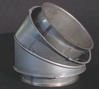
22 45 Elbow Part 45E Part includes: one 45 elbow, one vee band and one draw band. K = Elbow Part 30E Part includes: one 30 elbow, one vee band and one draw band. K = Elbow & Offsets (Inches) ID OD A B C D / / /32 9 3/ /16 6 1/4 15 3/ / / / / / /4 7 7/ / / /16 8 1/ / / /8 8 11/ / / /2 9 3/ / / / / / / / /8 25 3/ / / /2 18 3/ / / / / / / / / /4 30 3/4 21 3/ / / / / / / / / / / / / / / / / / / / / /2 16 1/4 39 1/4 27 3/ / / / / / / / / /4 18 1/ / /4 30 Elbow & Offset (Inches) ID OD A B C / / /32 4 9/ / / / /4 4 29/ / /2 5 7/ / / / / / / / /16 6 5/ / / / / /8 6 3/4 21 7/ /8 7 1/ / /32 7 3/8 23 7/ / / / / / /16 8 5/ / /32 8 5/8 27 7/ /4 8 15/ / /4 29 7/ /4 9 9/ / /32 9 7/8 31 7/ / / / / / /8 B A A C D D 20
23 15 Elbow Part 15E Part includes: one 15 elbow, one vee band and one draw band. End Cap with Drain Part C/D Used as a drain in a vertical tee section. Part includes: end cap with drain, vee band and draw band. K = Elbow and Offset (Inches ID OD A B C /8 1 1/2 11 7/ /16 1 9/ / /16 1 5/8 12 7/ / / / /16 1 3/4 13 1/ /16 1 7/ / / / / / /16 2 1/ / /16 2 1/8 16 1/ /4 2 3/ / /8 2 1/4 17 1/ /2 2 5/ / /8 2 3/8 18 1/ /4 2 7/ / /8 2 1/2 19 3/ / / /8 2 11/ / /4 2 3/8 20 3/ /8 2 13/ / /16 2 7/8 21 3/ / / /4 End Cap Part CAP Used on closed end to provide a clean out and inspection access port. Part includes: end cap, vee band and draw band. Barometric Damper Part BMD Atmospheric type draft regulator used to balance chimney draft requirements. 21
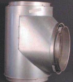
24 90 Centered Tee Part 90T This component is used to make 90 turns. Please specify projection diameter if different than main body diameter. Part includes: 90 tee, two vee bands, and two draw bands. OD ID K = 1.25 A A = Projection ID B = A + 8" for DW and DWplus B = A + 10" for DWplus2 B = A + 12" for DWplus3 B = A + 14" for DWplus4 C = Projection Length from Center Line DW and DWplus = 1/2"ID + 4" DWplus2 = 1/2"ID + 5" DWplus3 = 1/2"ID + 6" DWplus4 = 1/2"ID + 7" 1/2 ID C 4" 4" B 90 Centered Tee Section (Inches) Sect. ID Proj. ID DW/DWplus DWplus2 DWplus3 DWplus4 DW/DWplus DWplus2 DWplus3 DWplus4 A B B B B C C C C Chart is based on tees with full size projections. 22
25 90 Boot Tee Chart (Inches) 90 Boot Tee Part BTT This component is used to make low resistance 90 turns. In some applications this 90 boot tee can replace 45 tees and 45 elbows. Please specify projection diameter if different than main body diameter. Part includes: 90 boot tee, two vee bands and two draw bands. K =.65 A = Proj. I.D. + 12" for DW and DWplus A = Proj. I.D. + 14" for DWplus2 A = Proj. I.D. + 16" for DWplus3 A = Proj. I.D. + 18" for DWplus4 B = 1/2 Proj. I.D. + 4" for DW and DWplus B = 1/2 Proj. I.D. + 5" for DWplus2 B = 1/2 Proj. I.D. + 6" for DWplus3 B = 1/2 Proj. I.D. + 7" for DWplus4 C = B + 4" D = B + 2" Model DW / DWplus DWplus2 DWplus3 DWplus4 ID A B C D A B C D A B C D A B C D Chart is based on tees with full size projections. 23
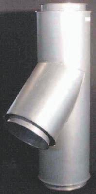
26 45 Tee Section Part 45T Use this component to make 45 turns. Please specify projection diameter if different than main body diameter. Part includes: 45 tee, two vee bands, and two draw bands. K =.40 Note: Projection ID of C determines length of A. 45 Tee Section (Inches) Section DW / DWplus DWplus2 DWplus3 DWplus4 ID A B C A B C A B C A B C / / / / / / / / / / / / / / / / / / / / / / / / / / / / / / / / / / / / / / / / / / / / / / / / / / / / / / / / / / / / / / / / / / / / / / / / / / / / / / / / /8 Chart is based on tees with full size projections. 24
27 45 Double Tee Section Part 45T / Use this component to make two 45 turns from different directions. Please specify projection diameter if different than main body diameter. Part includes: 45 tee, three vee bands and three draw bands. Note: Projection ID required. Projection ID of C determines length of A. K=.40 Double 45 Tee Section (Inches) Section DW / DWplus DWplus2 DWplus3 DWplus4 ID A B C A B C A B C A B C / / / / / / / / / / / / / / / / / / / / / / / / / / / / / / / / / / / / / / / / / / / / / / / / / / / / / / / / / / / / / / / / / / / / / / / / / / / / / /8 Chart is based on tees with one size smaller projections. 25
28 90 Wye Section Part WYE Used for joining two systems together or to provide cleanouts at 90 turns for grease duct and other applications with a minimum resistance to flow. Part includes: 90 wye, two vee bands, and two draw bands. K = 0.6 Increaser Part INC This part is used to provide a low resistance increase when diameter changes are required. * = Smaller diameter ** = Larger diameter A = 7 3/4" for one diameter size increase A = 11 1/2" for two diameter size increase A = 15 3/16" for three diameter size increase A = 19" for four diameter size increase Part includes: increaser, one small vee band, and one small draw band. Wye Chart (Inches) All Legs Equal Section DW & DWplus ID A B 6 5 5/32 7 1/ /32 8 1/ / / / / / / / / / / / / / /8 16 1/ / / / / /8 19 1/ / / / / /8 22 1/ / / / / /8 25 1/ / / / / / /2 12" Long Adapter Part ADT This part is used to provide an increase when insulation thickness changes are required. Part includes: adapter, one small vee band, and one small draw band. Guy Tensioner Part GUY1500 Van-Packer offers a 1500 lb. Guy Tensioner, which is good for up to 3 inches of expansion. Use the Guy Tensioner in conjunction with the Guy Attachment Ring. Installing contractor shall provide wire rope, thimble, clips, and any type of hardware for attachment to roof and or building. Van-Packer suggests using 1/4" minimum galvanized guying cable with the guy-attachment ring and guy-tension devices. 26
29 Guy Attachment Ring Part GAR The Guy Attachment Ring is used for lateral support. Part includes: four half clamp rings, nuts and bolts, and two half draw bands. 18" Long Eccentric Increaser Part ECC This part is used to provide an increase on one side of the pipe while the opposite side remains the same. Part includes: eccentric increaser, one small vee band, and one small draw band. This is a non-ul Listed component. A = 18" length for one through three steps A = Four steps and above (length same as increaser) Square to Round Transition Part STS This part is used to provide a connection from a square to round joint. Part includes: transition, blank flange, vee band and draw band. This is a non-ul Listed component. 18" Long Smoke Opacity Monitor Section Part SOM This part is used to provide a connection for smoke opacity monitoring for Preferred Controls. Vertical format is standard. Horizontal format for the Preferred Controls and Horizontal/Vertical format for Cleveland Controls can be fabricated and is considered custom. Part includes: smoke opacity monitor section, vee band and draw band. This is a non-ul Listed component. 18" Long Butterfly Damper Section Part DPR This part is used to control draft flow. It will not shut 100% and has a manual damper. Part includes: butterfly damper section, vee band and draw band. This is a non-ul Listed component. 27


30 Pressure Relief Valve Part ERV Use the Pressure Relief Valve to relieve pressure spikes. To be used in accordance with NFPA 37. Extreme care must be used when determining the location of this valve. If this valve is activated, hot gas, flames and toxicants will be released into the atmosphere (see General Installation Guidelines). Part includes: pressure relief valve, flange adapter, vee band, bolts and nuts. Conforms to NFPA 37. Vee Band Part VEE This part is used to connect Van-Packer Model DW, DWplus Series, Model SW and Model ES components for a positive pressure seal. When using Van-Packer s high temperature sealant, Part #101091F, this allows for 60" water column. UL Listed per UL Standard 103. Part includes: vee band, screws and square nuts. Draw Band Part DRW This part is used to connect Van-Packer Model DW and DWplus Series outer shells. The draw band seals the flue pipe and gives a uniform look. Part includes: draw band, screws and square nuts. Half Draw Band Part HDB This part is used to seal off Van-Packer Model DW and DWplus Series outer shells. The half draw band gives a uniform look. Part includes: one half draw band, screws and square nuts. 28

31 VAN-PACKER WARRANTS that its Model SW components will perform their intended function of exhausting the combustion products of heating equipment without adverse leakage provided the system has been sized in accordance with good engineering practice and that the material specifications are suitable for the application. This Warranty is given to the owner of the products against defects in workmanship and materials for a period of one year after delivery. This Warranty extends only to installations where the attached equipment is operated in accordance with the manufacturer s instructions. This Warranty is further limited only to those installations with normal effluent from a boiler or if the effluent is approved in writing by VAN-PACKER. Parts, products, or accessories manufactured by others are warranted only to the extent of the original manufacturer s warranty. VAN-PACKER S obligation under this warranty is limited to repair or replacement as it shall be determined by its sole discretion upon examination by qualified personnel, as approved by VAN-PACKER and only to that material produced or fabricated at our factory. The erection, installation, field fabrication or welding by installing contractors or VAN-PACKER distributors are warranted only to the extent of the installing contractor s or distributor s warranty. VAN-PACKER reserves the right to examine the chimney during the warranty period. Operation of the equipment must be maintained in accordance with the manufacturer s instructions. In the event a violation is observed, the problem must be corrected within 30 days to VAN-PACKER S satisfaction. In the event the violation is not corrected within 30 days, the Warranty becomes invalid. ALL IMPLIED WARRANTIES OF MERCHANTABILITY AND FITNESS FOR A PARTICULAR PURPOSE WHICH EXCEED VAN-PACKER S AFORESTATED OBLIGATION ARE HEREBY DISCLAIMED BY VAN-PACKER AND EXCLUDED FROM THE WARRANTY. The Warranties made herein by Van-Packer Company are in lieu of all other warranties, stated or inferred, and VAN-PACKER assumes no liability for loss of use or for any direct, indirect, or consequential damage of any kind in respect to the use or operation of VAN-PACKER products, or any equipment or accessories used in connection therewith. VAN-PACKER neither assumes nor authorizes any person to assume for it any obligation in connection with the sale of the products. This Warranty shall not apply to any products or parts of products which (a) have been repaired or altered in any manner outside of VAN-PACKER S factory unless designated in writing by VAN- PACKER; or (b) have been subjected to misuse, neglect or accident; or (c) have been used in a manner contrary to VAN-PACKER S printed instructions; or (d) damaged due to malfunction of the attached equipment or faulty installation.

32 VAN-PACKER WARRANTS that a chimney system consisting exclusively of components manufactured by it and installed in accordance with drawings and specifications approved in writing by it against functional failure due to defects in materials and workmanship, PROVIDED, that the effluent being and having been vented is and was described in writing agreed to by VAN-PACKER at the time VAN-PACKER approved the drawings and specifications pertaining to such chimney. Flue gas must remain above acid dew points. THIS WARRANTY IS FOR A PERIOD OF 10 YEARS - All rights and limitations pertaining to the warranty may be assigned by the original owner of the chimney to the person or entity purchasing the plant or facility in which the chimney is located. VAN-PACKER S sole obligation under this warranty is to repair or replace, as it shall determine in its sole discretion, any components that fail to comply with this warranty. This warranty does not cover any labor cost for the removal or replacement of any defective product. The Warranties made herein by Van-Packer Company, Inc. are in lieu of any and all other warranties, stated or inferred, and VAN-PACKER assumes no liability for loss of use or for any direct, indirect or consequential damage of any kind in respect to the use of operation of VAN-PACKER products, or any equipment or accessories used in connection therewith. VAN-PACKER does not authorize any person to assume for it any obligation in connection with the sale of the products. This Warranty shall not apply to any products or parts which (a) Have been repaired or altered in any manner outside of VAN-PACKER S factory; (b) Have been subjected to misuse, neglect or accident; (c) Have been used in a manner contrary to VAN-PACKER S printed instructions; or (d) Have been damaged due to malfunction of any attached or connected equipment or faulty installation. Van-Packer Company, Inc. will provide a signed warranty upon approval. Contact Van-Packer for details. Sales, Service and Manufacturing 302 Mill Street, P.O. Box 307, Buda, Illinois Phone Toll Free Fax vpstack@theramp.net Web Site: 01/2005#140
RECTANGULAR, 2-HOUR FIRE RATED, ZERO-CLEARANCE GREASE DUCT CO.
 RECTANGULAR, 2-HOUR FIRE RATED, ZERO-CLEARANCE GREASE DUCT CO. For over 75 years, Van-Packer has supplied venting products to the Commercial and Industrial heating and process markets. For the past 30
Model DW Series Positive Pressure Guidelines for Engine Exhaust Systems
 1 Model DW Series Positive Pressure Guidelines for Engine Exhaust Systems UL Listed under Standard 103 for Flue Gas Temperatures up to 1400 F (759 C) Venting System for Factory-Built Chimneys For Building
Model DW Series Positive Pressure Guidelines for Engine Exhaust Systems
 Model DW Series Positive Pressure Guidelines for Engine Exhaust Systems UL Listed Under: UL 103 / ULC ORD C959 UL 2561 / ULC ORD C959 UL 641 / ULC S609 1 Please note these instructions cover the additional
venting systems for high efficiency appliances series
 venting systems for high efficiency appliances series LISTINGS The Schebler event and event PLUS system are tested and listed by Underwriters Laboratories Inc. (UL) under file number MH10056 for UL 1738
Model VSI-I & VSI-II Positive Pressure Venting Systems
 C O M M E R C I A L A N D I N D U S T R I A L V E N T I N G Model VSI-I & VSI-II Positive Pressure Venting Systems Ideal for discharging exhaust gases and fumes from boilers, heaters, ovens, engines, turbines
RECEIVING AND INSPECTION EXAMINE ALL COMPONENTS FOR POSSIBLE SHIPPING DAMAGE PRIOR TO INSTALLATION.
 Non-Welded Grease Duct Systems Installation, Operation, and Maintenance Manual FOR YOUR SAFETY TWO MAJOR CAUSES OF GREASE DUCT RELATED FIRES: (1) FAILURE TO MAINTAIN REQUIRED CLEARANCE (AIR SPACE) TO COMBUSTIBLE
Saf-T Vent EZ Seal. Technical and Dimensional Data. Single Wall AL 29-4C Stainless Steel Special Gas Vent
 Technical and Dimensional Data Saf-T Vent EZ Seal Single Wall AL 29-4C Stainless Steel Special Gas Vent 130 Industrial Boulevard Turners Falls, MA 01376 Copyright 2001 Heat-fab, Incorporated Saf-T Vent
RECEIVING AND INSPECTION
 Non-Welded Grease Duct Systems Installation, Operation, and Maintenance Manual FOR YOUR SAFETY TWO MAJOR CAUSES OF GREASE DUCT RELATED FIRES: (1) FAILURE TO MAINTAIN REQUIRED CLEARANCE (AIR SPACE) TO COMBUSTIBLE
Models PS/IPS. Stainless Steel Double Wall Positive Pressure Piping Systems FEATURES CATALOG
 CATALOG Models PS/IPS Stainless Steel Double Wall Positive Pressure Piping Systems Selkirk Commercial & Industrial Models PS and IPS are modular, prefabricated piping systems which embody flanged joints
SELKIRK CORP INSTALLATION INSTRUCTION SUPPLEMENT MODEL G - CHIMNEY LINER
 SELKIRK CORP MODEL G - CHIMNEY LINER These instructions are supplemental to the General Installation Instructions for Selkirk Model G, PS, IPS and ZC Single Wall, Double Wall Air & Fiber Insulated Positive
MODEL P4. Chimney and Exhaust Systems. Underwriters c. Laboratories Inc. LISTED
 MODEL P4 Chimney and Exhaust Systems UL UL Underwriters c Laboratories Inc. LISTED LISTINGS The Schebler Model P4 chimney and exhaust system is listed by Underwriters Laboratories Inc. (UL) under file
INSTALLATION AND MAINTENANCE INSTRUCTIONS
 INSTALLATION AND MAINTENANCE INSTRUCTIONS MODEL PIC/IPIC CHIMNEY AND VENTS PIC IPIC This symbol on the nameplate means this product is listed by Underwriters Laboratories Inc. and by Underwriters Laboratories
INSTALLATION AND MAINTENANCE INSTRUCTIONS
 INSTALLATION AND MAINTENANCE INSTRUCTIONS MODEL IPIC GREASE DUCT AND CHIMNEY IPIC This symbol on the nameplate means this product is listed by Underwriters Laboratories Inc. and by Underwriters Laboratories
MODEL PA. Chimney and Exhaust Systems. Underwriters c. Laboratories Inc. LISTED
 MODEL P Chimney and Exhaust Systems UL UL Underwriters c Laboratories Inc. LISTED LISTINGS The Schebler Model P chimney and exhaust system is listed by Underwriters Laboratories Inc. (UL) under file number
MODEL P1. Chimney and Exhaust Systems. Underwriters c. Laboratories Inc. LISTED
 MODEL P1 Chimney and Exhaust Systems UL UL Underwriters c Laboratories Inc. LISTED LISTINGS The Schebler Model P1 chimney and exhaust system is listed by Underwriters Laboratories Inc. (UL) under file
MODEL P2A. Chimney and Exhaust Systems. Underwriters c. Laboratories Inc. LISTED
 MODEL P2 Chimney and Exhaust Systems UL UL Underwriters c Laboratories Inc. LISTED LISTINGS The Schebler Model P2 chimney and exhaust system is listed by Underwriters Laboratories Inc. (UL) under file
Table of Contents WARRANTY...3 APPLICATION...4 MECHANICAL...5 Joint Sealant...5 Grease Duct Standard Connection...6 Collar and Adjustable Duct
 Non-Welded Grease Duct Systems Installation, Operation, and Maintenance Manual FOR YOUR SAFETY TWO MAJOR CAUSES OF GREASE DUCT RELATED FIRES: () FAILURE TO MAINTAIN REQUIRED CLEARANCE (AIR SPACE) TO COMBUSTIBLE
Series. Chimney System for High Efficiency Appliances. Underwriters c. Laboratories Inc. LISTED
 Series Chimney System for High Efficiency ppliances UL UL Underwriters c Laboratories Inc. LISTED LISTINGS The Schebler event and eventplus system are tested and listed by Underwriters Laboratories Inc.
DuraChimney II. Air-cooled chimney system for masonry fireplaces. UL 103.
 DuraChimney II Air-cooled chimney system for masonry fireplaces. UL 103. Specifications Applications DuraChimney II is a double-wall, air-cooled chimney system for use with masonry fireplaces which burn
Saf-T Vent EZ Seal. Technical and Dimensional Data. Single Wall AL 29-4C Stainless Steel Special Gas Vent
 Technical and Dimensional Data Saf-T Vent EZ Seal Single Wall L 29-4 Stainless Steel Special Gas Vent Tested and Listed to UL 1738/UL S636 by Underwriters Laboratories, Inc opyright 2008 Selkirk orp. Saf-T
HP190SL Series Slimline Radon Fans
 Installation and Operation Manual Item #: 412843 Rev Date: 070113 HP190SL Series Slimline Radon Fans United States 10048 Industrial Blvd., Lenexa, KS, 66215 Tel.: 800.747.1762 Fax: 800.487.9915 Canada
Technical and Dimensional Data. Double Wall One Inch Air Space AL 29-4C Stainless Steel Special Gas Vent
 $5 Technical and Dimensional Data Saf-T Vent CI Plus Double Wall One Inch Air Space AL 29-4C Stainless Steel Special Gas Vent For Venting Commercial & Industrial Appliances Condensing Appliances Category
CSA CERTIFIED Conforms to UL 507
 Installation tion Instructions Please read and save these instructions! TURBO/MAXX12 Volt All Weather RV Ventilator Fans P/N 00-965001 Deluxe Model 1200T WITH THERMOSTAT P/N 00-965007 Standard Model 3550
Saf-T Vent EZ Seal. Technical and Dimensional Data. Single Wall AL 29-4C Stainless Steel Special Gas Vent
 Technical and Dimensional Data Saf-T Vent EZ Seal Single Wall L 29-4 Stainless Steel Special Gas Vent Tested and Listed to UL 1738/UL S636 by Underwriters Laboratories, Inc 5030 orporate Exchange lvd Grand
Installation Instructions
 Equipment Required: Installation Instructions Fastener Kit: F Wrenches: 8mm, 13mm, 3/4, 15/16 Drill Bits: 1/4 Other Tools: Drill, Reciprocating Saw, File WARNING: Under no circumstances do we recommend
Single-Position Detent Clutch DC Series. (i) MTY (81) MEX (55) QRO (442)
 MTY (81) MEX (55) QRO (442)") Single-Position Detent Clutch DC Series (i) FORM NO. L-2017-A-001 In accordance with Nexen s established policy of constant product improvement, the specifications contained in this manual are subject
Single-Position Detent Clutch DC Series (i) FORM NO. L-2017-A-001 In accordance with Nexen s established policy of constant product improvement, the specifications contained in this manual are subject
venting systems for high efficiency appliances series
 venting systems for high efficiency appliances series SUPERIOR SYSTEM DESIGN event DualSeal with RapidLock Connection System is a modular double wall prefabricated vent and exhaust systems used in venting
Installation Instructions
 Equipment Required: Installation Instructions Fastener Kit: F Wrenches: 8mm, 13mm, 3/4, 15/16 Drill Bits: 1/4 Other Tools: Drill, Reciprocating Saw, File WARNING: Under no circumstances do we recommend
Saf-T Vent EZ Seal. Technical and Dimensional Data. Single Wall AL 29-4C Stainless Steel Special Gas Vent
 Technical and Dimensional Data Saf-T Vent EZ Seal Single Wall L 29-4 Stainless Steel Special Gas Vent Tested and Listed to UL 1738/UL S636 by Underwriters Laboratories, Inc 5030 orporate Exchange lvd Grand
INSTALLATION INSTRUCTIONS ISLAND LINER INSERT
 Read and Save These Instructions All Hoods Must Be Installed By A Qualified Installer INSTALLATION INSTRUCTIONS ISLAND LINER INSERT Read All Instructions Thoroughly Before Beginning Installation WARNING
Model N. Stainless Steel Double Wall Positive Pressure Venting Systems. Special Gas Vent Applications COMMERCIAL AND INDUSTRIAL VENTING
 COMMERCIL ND INDUSTRIL VENTING Model N Stainless Steel Double Wall Positive Pressure Venting Systems Special Gas Vent pplications Model N is a single wall negative, neutral, or positive pressure pre-fabricated
INSTALLATION INSTRUCTIONS K SERIES LINER INSERT
 Read and Save These Instructions All Hoods Must Be Installed By A Qualified Installer INSTALLATION INSTRUCTIONS K SERIES LINER INSERT Read All Instructions Thoroughly Before Beginning Installation WARNING
INDUSTRIES AMERICAN COOLAIR CORPORATION. Centrifugal Filtered Supply Roof Ventilators TYPE CFS - TYPE SIS
 INDUSTRIES AMERICAN COOLAIR CORPORATION Centrifugal Filtered Supply Roof Ventilators TYPE CFS - TYPE SIS CFS Centrifugal Filtered Supply Fans Applications The CFS Centrifugal Filtered supply fans with
SECTION AXIAL HVAC FANS
 SECTION 233413 - AXIAL HVAC FANS 1. PART 1 GENERAL 1.1. RELATED DOCUMENTS A. Drawings and general provisions of the Contract, including General and Supplementary Conditions and Division 01 Specification
Model ND-2 Specification
 Model ND-2 Specification The model ND-2 is an exhaust only canopy hood rated for all types of cooking equipment. The hood shall have the size, shape and performance specified on drawings. Construction
Modular Double-Wall Positive Pressure Chimney Boiler Breeching & Stack and Engine Exhaust Grease Duct
 Modular Double-Wall Positive Pressure himney oiler reeching & Stack and Engine Exhaust Grease Duct DuraStack Pro Modular Double-Wall Positive Pressure himney oiler reeching & Stack and Engine Exhaust DuraStack
Gas Venting Systems residential industrial commercial
 Gas Venting Systems residential industrial commercial AirJet Gas Vent AirJet Gas Vent is listed by Underwriters Laboratories, Standard UL-441, and accepted by FHA, VA, BOCA, ICBO and SBCted by Underwriters
ELECTRIC SHOCK HAZARD/FIRE AND/OR EXPLOSION HAZARD. ELECTRIC SHOCK HAZARD/FIRE AND/OR EXPLOSION HAZARD.
 INSTALLATION INSTRUCTIONS FOR CONCENTRIC VENT KIT P/N AOPS7483 (for 4 flue roof jack) CONCENTRIC VENT KIT P/N AOPS7544 (for 5 flue roof jack) DUAL PIPE FLASHING KIT P/N AOPS7484 ELECTRIC SHOCK HAZARD/FIRE
NUTONE RANGE HOOD NTM SERIES
 INSTALLATION INSTRUCTIONS READ AND SAVE THESE INSTRUCTIONS HB0043 NUTONE RANGE HOOD NTM SERIES IMPORTANT SAFETY INSTRUCTIONS IMPORTANT SAFETY INSTRUCTIONS! WARNING TO REDUCE THE RISK OF FIRE, ELECTRIC
Grinnell Grooved Fire Protection Products Grooved Fittings
 Technical Services: Tel: (800) 38-932 / Fax: (800) 79-5500 www.tyco-fire.com Grinnell Grooved Fire Protection Products Grooved Fittings General Description LPCB Vd S The grooved fittings provide an economical
CENTRIFUGAL UPBLAST ROOF EXHAUSTERS Model VRBK
 CENTRIFUGAL UPBLAST ROOF EXHAUSTERS Model VRBK CENTRIFUGAL UPBLAST ROOF EXHAUSTERS COMMERCIAL KITCHEN APPLICATIONS Belt Driven Model VRBK DESIGNED AND ENGINEERED TO MEET INDUSTRY NEEDS The Carnes Company
FADE Series Wall Axial Fans
 Installation and Operation Manual Item #: 401442 Rev Date: 070113 FADE Series Wall Axial Fans Fantech Inc. certifies that the FADE Series shown herein is licensed to bear the AMCA Seal. The ratings shown
8" - 12" Hydraulic Steel Squeeze Off Tool
 8" - 12" Hydraulic Steel Squeeze Off Tool ECN 19130 C812S Hydraulic Steel Squeeze Off Tool for Steel Pipe Page 1 of 8 This Footage Tools C812S Steel Squeeze Off Tool is sold with one pump configuration
Model Description Vac. Max rating Pedestal Only: 36 Utility Pedestal W/O Disconnect General Duty Series:
 MAPA Products MPD-XX / Pedestal Disconnect 30, 60, 100 amp February 2014 Pedestal Disconnect Installation Instructions Parts List MAPA Products Fusible Rainproof Pedestal Mounted Safety Switch provides
Installation Instructions
 Equipment Required: Fastener Kit: F Wrenches: 3/4, 15/16, 13mm Drill Bits: 1/4, some older models a 1/2 Other Tools: Drill, Saber Saw 5/8 Fasteners From Hitch Fastener Kit Installation Instructions GOOSENECK
Air Curtain. Installation, Operating and Maintenance Instructions
 Installation, Operating and Maintenance Instructions Save this manual for future reference. Air Curtain Model Numbers: ES026, ES036, ES042, ES048, ES060, ES072 READ THIS OWNER S MANUAL CAREFULLY BEFORE
Operating and Installation Instructions
 Model Number 20902 Fabricator's Power Module Kit - Aluminum Operating and Installation Instructions CAUTION! This product is to be installed only by persons knowledgeable in the repair and modification
ELECTRONIC FIREPLACE DAMPER
 ELECTRONIC FIREPLACE DAMPER Model: FSE Low Profile Series The Flue Sentinel Electronic Fireplace Damper is designed to increase the comfort and energy efficiency of residential homes with gas-fired fireplaces.
Installation Instructions
 Equipment Required: Fastener Kit: F Wrenches: 3/4, 15/16 Drill Bits: 1/4 Other Tools: Drill Short & Long Bed All Megacabs 9464/9474 HIDE-A-GOOSE HITCH INSTALLATION WARNING: Under no circumstances do we
Installation Instructions
 Installation Instructions Models: SLP Venting System These venting system components have been tested for use with approved HHT Direct Vent appliances. Check with your local building code agency before
Operators Manual for JES-HD
 Operators Manual for JES-HD Heavy Duty Jet Extraction System Manual provides Operation, Maintenance and Service Instructions Heavy Duty Jet Extraction System Model: JES-HD Form#: OM038_JES-HD_Jet_Extraction_System
MODEL HD-BTC. Installation, Operation & Repair Parts Information REV041416
 MODEL HD-BTC Installation, Operation & Repair Parts Information REV041416 TABLE OF CONTENTS SAFETY INSTRUCTIONS 1 DEFINITIONS 1 SPECIFICATIONS 2 INSTALLATION INSTRUCTIONS 2 OPERATING INSTRUCTIONS 2 MAINTENANCE
Stovepipe DVL. DuraBlack. Double-wall interior stovepipe for connecting woodstoves to chimney. ULC S641.
 Stovepipe DVL Double-wall interior stovepipe for connecting woodstoves to chimney. ULC S641. Duralack Single-wall interior stovepipe for connecting woodstoves to chimney. Specifications DVL Applications
INSTALLATION INSTRUCTIONS WALL MOUNT RANGE HOOD WITH M600 OR M1200 BLOWER
 WARNING - TO REDUCE THE RISK OF FIRE, USE ONLY METAL DUCTWORK C U L R Read and Save These Instructions All Hoods Must Be Installed By A Qualified Installer INSTALLATION INSTRUCTIONS WALL MOUNT RANGE HOOD
INSTALLATION INSTRUCTIONS WALL MOUNT RANGE HOOD WITH M600 OR M1200 BLOWER
 WARNING - TO REDUCE THE RISK OF FIRE, USE ONLY METAL DUCTWORK C U L R Read and Save These Instructions All Hoods Must Be Installed By A Qualified Installer INSTALLATION INSTRUCTIONS WALL MOUNT RANGE HOOD
INSTALLATION INSTRUCTIONS EUROLINE/EUROLINE PRO WALL MOUNT HOOD
 Read and Save These Instructions All Hoods Must Be Installed By A Qualified Installer INSTALLATION INSTRUCTIONS EUROLINE/EUROLINE PRO WALL MOUNT HOOD Read All Instructions Thoroughly Before Beginning Installation
THE GAYLORD VENTILATOR TECHNICAL MANUAL FOR THE GRAND VH2 AND HH SERIES TYPE II HOODS GAYLORD INDUSTRIES
 EFFECTIVE DATE 5-04 THE GAYLORD VENTILATOR TECHNICAL MANUAL FOR THE GRAND VH2 AND HH SERIES TYPE II HOODS 10900 S.W. AVERY STREET P.O. BOX 1149 TUALATIN, OREGON 97062-1149 U.S.A. 800-547-9696 503-691-2010
INSTALLATION INSTRUCTIONS AH12 WALL MOUNT HOOD
 Read and Save These Instructions All Hoods Must Be Installed By A Qualified Installer INSTALLATION INSTRUCTIONS AH12 WALL MOUNT HOOD Read All Instructions Thoroughly Before Beginning Installation WARNING
INSTALLATION INSTRUCTIONS JDH/C2 DESIGNER SERIES WALL MOUNT HOOD
 WARNING - TO REDUCE THE RISK OF FIRE, USE ONLY METAL DUCTWORK C U L R Read and Save These Instructions All Hoods Must Be Installed By A Qualified Installer INSTALLATION INSTRUCTIONS JDH/C2 DESIGNER SERIES
Installation Instructions
 Equipment Required: Fastener Kit: F Wrenches: 15/16, 15/16 Crowfoot Adaptor Drill Bits: 1/4 Other Tools: Drill, Reciprocating saw Optional, Raise Bed: 18mm socket, 15 extension As an option you can loosen
INSTALLATION INSTRUCTIONS EUROLINE/EUROLINE PRO WALL MOUNT HOOD
 WARNING - TO REDUCE THE RISK OF FIRE, USE ONLY METAL DUCTWORK C U L R Read and Save These Instructions All Hoods Must Be Installed By A Qualified Installer INSTALLATION INSTRUCTIONS EUROLINE/EUROLINE PRO
INSTALLATION INSTRUCTIONS EUROLINE/EUROLINE PRO WALL MOUNT HOOD
 WARNING - TO REDUCE THE RISK OF FIRE, USE ONLY METAL DUCTWORK C U L R Read and Save These Instructions All Hoods Must Be Installed By A Qualified Installer INSTALLATION INSTRUCTIONS EUROLINE/EUROLINE PRO
INSTALLATION INSTRUCTIONS CWUH9 WALL MOUNT HOOD
 Read and Save These Instructions All Hoods Must Be Installed By A Qualified Installer INSTALLATION INSTRUCTIONS CWUH9 WALL MOUNT HOOD Read All Instructions Thoroughly Before Beginning Installation WARNING
SAM-e. Engineering Manual
 Your guide to selecting and specifying Nortec SAM-e Short Absorption Manifolds! SAM-e Engineering Manual Includes technical specifications, guidelines, and options for selection and application of SAM-e
Residential and Light Commercial Products. May Page 1
 Residential and Light Commercial Products May 2007 Page 1 MIDWEST DUCTS May 2007 TABLE OF CONTENTS ALUMINUM PRODUCTS Page 18 ANGLES (ROUND) Page 7 ANGLES (SQUARE) Page 5 BASEMENT HEADS Page 13 BOOTS Page
SECTION CENTRIFUGAL HVAC FANS
 SECTION 233416 - CENTRIFUGAL HVAC FANS 1. PART 1 GENERAL 1.1. RELATED DOCUMENTS A. Drawings and general provisions of the Contract, including General and Supplementary Conditions and Division 01 Specification
Model BP6150. Triplex Ceramic Plunger Pump Operating Instructions/ Manual
 Model BP6150 Triplex Ceramic Plunger Pump Operating Instructions/ Manual Contents: Installation Instructions: page 2 Pump Specs: page 3 Exploded View: page 4 Parts List / Kits Torque Specifications: page
Tube Axial Fan Page Specifications & Dimension Data Performance Data
 Tube Axial Fan Page Introduction........................................... 2 Construction Features................................... 3 Information........................................... 4 Specifications
MODELS TSX AND TSX-S SINGLE DUCT ROUND AIR TERMINALS
 MODELS TSX AND TSX-S SINGLE DUCT ROUND AIR TERMINALS INSTALLATION OPERATION & MAINTENANCE New Release Form 130.13-NOM4 (908) In conjunction with the use of these instructions, obtain and refer to the construction,
Models GP5132, GP5136, GP5142 & GP5145. Triplex Ceramic Plunger Pump Operating Instructions / Manual
 Models GP5132, GP5136, GP5142 & GP5145 Triplex Ceramic Plunger Pump Operating Instructions / Manual Updated 07/14 Contents: Installation Instructions: page 2 Pump Specifications: page 3 Exploded View:
GE Monogram. Installation. Instructions. Professional Vent Hoods. 48" Models ZV881WSS, ZV891YSS ZV880WSS, ZV890YSS. 36" Models ZV671WSS, ZV681YSS
 GE Monogram Installation Instructions Professional Vent Hoods 48" Models ZV881WSS, ZV891YSS ZV880WSS, ZV890YSS 36" Models ZV671WSS, ZV681YSS ZV670WSS, ZV680YSS 30" Models ZV370YSS, ZV371YSS CAUTION WARNING
THE WARRANTY SET FORTH HEREIN IS GIVEN EXPRESSLY AND IS THE ONLY WARRANTY GIVEN BY THE COMPANY WITH RESPECT TO THE PRODUCT.
 Series 909 Reduced Pressure Zone Backflow Preventers Sizes: 3 /4" 2" (20 50mm) Installation Service Repair Kits Maintenance No. 1 1 2" shown Patent Number 4,241,752 IMPORTANT: Inquire with governing authorities
Installation Manual DIAPHRAGM WELL TANK
 Installation Manual DIAPHRAGM WELL TANK IN-LINE SERIES: 2-5 & 7 GALLON VERTICAL SERIES: 14-20-25-32-36-52-65-86-96-119 GALLON HORIZONTAL SERIES: 7-14 & 20 GALLON NO LEAD NO LEAD: The weighted average of
Installation Instructions
 Equipment Required: Fastener Kit: F Wrenches: 3/4, 15/16, 13mm Drill Bits: 1/4, some older models a 1/2 Other Tools: Drill, Saber Saw 5/8 Fasteners From Hitch Fastener Kit Installation Instructions GOOSENECK
Installation Instructions
 Equipment Required: Fastener Kit: F Wrenches: 15/16, 15/16 Crowfoot Adaptor Drill Bits: 1/4 Other Tools: Drill, Reciprocating saw Optional, Raise Bed: 18mm socket, 15 extension As an option you can loosen
Installation, Operation and Maintenance Manual
 Commercial Kitchen Hood Installation, Operation and Maintenance Manual www.fastkitchenhood.com General Information Prior to installing the stainless steel ventilation hood, the installing contractor should
ISIMET/MAPA, LLC, an affiliate of WCM Industries, Inc. 103 CJ Wise Parkway Naples, TX (903) fax (903)
 fax (903)") ISIMET/MAPA, LLC, an affiliate of WCM Industries, Inc. 103 CJ Wise Parkway Naples, TX 75568 (903) 897-0737 fax (903) 897-0740 Pedestal Starter-Disconnect Pedestal Starter Controller Installation Instructions
ISIMET/MAPA, LLC, an affiliate of WCM Industries, Inc. 103 CJ Wise Parkway Naples, TX 75568 (903) 897-0737 fax (903) 897-0740 Pedestal Starter-Disconnect Pedestal Starter Controller Installation Instructions
MODELS SGX AND SSX SINGLE DUCT ROUND AIR TERMINALS
 BY JOHNSON CONTROLS INSTALLATION OPERATION & MAINTENANCE MODELS SGX AND SSX SINGLE DUCT ROUND AIR TERMINALS New Release Form ET130.13-NOM4 (908) In conjunction with the use of these instructions, obtain
Installation Instructions GOOSENECK MOUNTING KIT Chevrolet/GMC 1500/2500/3500 All except 4-door Crew-Cab
 GOOSENECK MOUNTING KIT Equipment Required: Fastener Kit: F Wrenches: 3/4, 7/8, 15/16 Drill Bits: 1/4 Other Tools: Drill WARNING: Under no circumstances do we recommend exceeding the towing vehicle manufacturers
Roof Upblast and Sidewall Exhaust
 XRUB, XRUD, XSEB, XSED, and XRUBS models are listed for electrical (UL/C-UL US 705) File no. E40001 and for grease removal (UL/C-UL US 762) File no. MH11745. Accurex, LLC certifies model XRUB, XRUD, XSEB,
Roof Upblast and Sidewall Exhaust
 XRUB, XRUD, XSEB, XSED, and XRUBS models are listed for electrical (UL/C-UL US 0) File no. E000 and for grease removal (UL/C-UL US ) File no. MH. Accurex, LLC certifies model XRUB, XRUD, XSEB, XSED, and
DAP-625S and DAP-875S
 AIR CHAMP PRODUCTS DAP-625S and DAP-875S (i) FORM NO. L-20078-B-0501 In accordance with Nexen s established policy of constant product improvement, the specifications contained in this manual are subject
Model F822 thru F834 Mulsifyre Directional Spray Nozzles, Open, High Velocity General Description
 Technical Services: Tel: () 31-931 / Fax: () 791-55 Model F thru F3 Mulsifyre Directional Spray Nozzles, Open, High Velocity General Description The Mulsifyre Nozzles are open (nonautomatic) nozzles and
INSTALLATION INSTRUCTIONS K-SERIES UNDER CABINET HOOD
 Read and Save These Instructions All Hoods Must Be Installed By A Qualified Installer INSTALLATION INSTRUCTIONS K-SERIES UNDER CABINET HOOD Read All Instructions Thoroughly Before Beginning Installation
Tubular Centrifugal Fans
 Tubular Centrifugal Fans Model TCB Inline - Horizontal or Vertical Roof Upblast and Roof Supply March 2007 Tubular Centrifugal Fans The TCB series of inline centrifugal fans is designed for ducted inline,
PENBERTHY FROST PROOF EXTENSION INSTALLATION, OPERATION AND MAINTENANCE INSTRUCTIONS
 Before installation these instructions must be read fully and understood PRODUCT WARRANTY Emerson warrants its Penberthy products as designed and manufactured to be free of defects in the material and
INSTALLATION INSTRUCTIONS WALL MOUNT HOOD
 Read and Save These Instructions All Hoods Must Be Installed By A Qualified Installer INSTALLATION INSTRUCTIONS WALL MOUNT HOOD Read All Instructions Thoroughly Before Beginning Installation WARNING -
INSTALLATION INSTRUCTIONS ISLAND RANGE HOOD
 Read and Save These Instructions All Hoods Must Be Installed By A Qualified Installer INSTALLATION INSTRUCTIONS ISLAND RANGE HOOD Read All Instructions Thoroughly Before Beginning Installation WARNING
Colt Series C400, C500
 Colt Series C400, C500 RP/IS-A-C400/C500 C400 OSY Reduced Pressure Zone Assemblies Reduced Pressure Detector Assemblies Sizes: 2 1 2" 10" (65 250mm) Installation Service Repair Kits Maintenance For other
INSTALLATION INSTRUCTIONS EUROLINE/EUROLINE PRO ISLAND RANGE HOOD
 WARNING - TO REDUCE THE RISK OF FIRE, USE ONLY METAL DUCTWORK C U L R Read and Save These Instructions All Hoods Must Be Installed By A Qualified Installer INSTALLATION INSTRUCTIONS EUROLINE/EUROLINE PRO
AEROMOTIVE Part # Ford 5.4L GT500 Shelby Mustang Fuel Rail Kit INSTALLATION INSTRUCTIONS
 AEROMOTIVE Part # 14145 07 Ford 5.4L GT500 Shelby Mustang Fuel Rail Kit INSTALLATION INSTRUCTIONS CAUTION: Installation of this product requires detailed knowledge of automotive systems and repair procedures.
DVL & DuraBlack. Simpson Dura-Vent Engineered Excellence
 DVL & Duralack Simpson Dura-Vent Engineered Excellence DVL pplications Double-wall interior stovepipe for connecting wood stoves to manufactured chimney. Materials and Construction.016 stainless steel
INSTALLATION INSTRUCTIONS CWSH3 WALL MOUNT HOOD
 Read and Save These Instructions All Hoods Must Be Installed By A Qualified Installer INSTALLATION INSTRUCTIONS CWSH3 WALL MOUNT HOOD Read All Instructions Thoroughly Before Beginning Installation WARNING
INSTALLATION INSTRUCTIONS EUROLINE/EUROLINE PRO ISLAND RANGE HOOD
 Read and Save These Instructions All Hoods Must Be Installed By A Qualified Installer INSTALLATION INSTRUCTIONS EUROLINE/EUROLINE PRO ISLAND RANGE HOOD Read All Instructions Thoroughly Before Beginning
INSTALLATION INSTRUCTIONS CWEH6-K WALL MOUNT HOOD
 Read and Save These Instructions All Hoods Must Be Installed By A Qualified Installer INSTALLATION INSTRUCTIONS CWEH6-K WALL MOUNT HOOD Read All Instructions Thoroughly Before Beginning Installation WARNING
Elgin Hydraulic Clutch-Brake ECB-240, Product Number FORM NO. L F FORM NO. L F-0704
 Elgin Hydraulic Clutch-Brake ECB-20, Product Number 96225 FORM NO. L-20283-F-070 1 FORM NO. L-20283-F-070 In accordance with Nexen s established policy of constant product improvement, the specifications
2017 Price List 2018 Price List
 Effective January 1, 2017 2017 Price List 2018 Price List Effective January 31, 2018 Table of Contents Solid Door Refrigerators... 3 Solid Door Pass-Thru Refrigerators... 4 Glass Door Refrigerators...
DISCONTINUED VERSION Parts listed in this catalog may no longer be available. ILLUSTRATED PARTS CATALOG BUNN-O-MATIC CORPORATION
 BUNN TWF-EZ DISCONTINUED VERSION Parts listed in this catalog may no longer be available. ILLUSTRATED PARTS CATALOG Designs, materials, weights, specifications, and dimensions for equipment or replacement
Standard Installation Combination Fire/Smoke Damper Models: FS1(SS), FS2(SS) Fire Damper Models: MD19(SS)
, FS2(SS) Fire Damper Models: MD19(SS)") Standard Installation Combination Fire/Smoke Damper Models: FS1(SS), FS2(SS) Fire Damper Models: MD19(SS) Page 1 of 6 APPLICATION These dynamically rated fire/smoke and fire s are intended to restrict
Standard Installation Combination Fire/Smoke Damper Models: FS1(SS), FS2(SS) Fire Damper Models: MD19(SS) Page 1 of 6 APPLICATION These dynamically rated fire/smoke and fire s are intended to restrict
WhispAire Range Hood Quiet Hood
 INSTALLATION INSTRUCTIONS READ & SAVE THESE INSTRUCTIONS WhispAire Range Hood Quiet Hood IMPORTANT SAFETY INSTRUCTIONS WARNING - TO REDUCE THE RISK OF FIRE, ELEC- TRIC SHOCK, OR INJURY TO PERSONS, OBSERVE