2/2-Way and T Valve Bodies in Stainless Steel
|
|
|
- Lynne Rogers
- 6 years ago
- Views:
Transcription


1 2/2-Way and T Valve Bodies in Stainless Steel


2 Leading the world in pharmaceutical and biotechnology industry sterilisation processes GEMÜ is one of the leading manufacturers of valves, measurement and control systems and is the world market leader for sterile valve applications in the pharmaceutical and biotechnology industries. This position is based on GEMÜ's comprehensive investments in application-oriented research & development, amounting to more than 5% of the company's turnover. Customized solutions for your project business GEMÜ provides the optimal solution from a single source. As a system supplier of isolation, actuator and control technology, we can respond very fl exibly to your individual project-specifi c needs. Our worldwide sales network provides fast reaction times, customer oriented service and a committed project management team.
3 Table of contents 2/2-Way Valve Bodies Description of use 4 Material selection 5 Grades of surface finish 6 Butt weld connections 7 Selection of operators 8-10 Butt weld spigots for EN ISO 1127 pipes, code Butt weld spigots for DIN pipes, code 0 12 Butt weld spigots for DIN pipes, series 1, code Butt weld spigots for DIN pipes, series 2, code 17; DIN 11866, series A, code 1A 14 Butt weld spigots for DIN pipes, series 3, code Butt weld spigots for ASME BPE pipes, code Butt weld spigots for BS 4825 pipes, code Butt weld spigots for JIS-G 3447 pipes, code Butt weld spigots for JIS-G 3459 pipes, code Butt weld spigots for SMS 3008 pipes, code Clamp bodies 21 Clamps ASME BPE for ASME BPE pipes, short design, code Clamps following ASME BPE for EN ISO 1127 pipes, code Clamps ASME BPE for ASME BPE pipes, code Clamps DIN for DIN pipes, code 8A 25 Clamps SMS 3017 for SMS 3008 pipes, code 8E 26 Clamps IDF/ISO for JIS-G 3447 pipes, code 8F 27 Clamps IDF/ISO for JIS-G 3459 pipes, code 8H 28 Clamp ASME BPE (short design), code 80 - butt weld spigot ASME BPE, code Clamp ASME BPE, length EN series 7, code 82 - butt weld spigot EN ISO 1127, code Clamp ASME BPE, length EN series 7, code 88 - butt weld spigot ASME BPE, code Clamp DIN 32676, code 8A - butt weld spigot DIN series 1, code Clamp DIN 32676, code 8A - butt weld spigot DIN series 2, code Clamp DIN 32676, code 8A - butt weld spigot DIN series 3, code Clamp IDF/ISO for JIS-G 3447 pipes, code 8F - butt weld spigot JIS-G 3447, code Clamp IDF/ISO for JIS-G pipes, code 8H - butt weld spigot JIS-G 3459, code Clamp SMS 3017, length EN series 7, code 8E - butt weld spigot SMS 3008, code Aseptic clamps 38 Dairy pipe and aseptic unions 39 Aseptic flanges 40 Kv value 41 Order code 42 Angle of rotation for optimum draining 43 GEMÜ angle gauge 44 T valve bodies Description of use 45 Material selection 46 Grades of surface finish 47 T valve bodies for sampling, body version "A" 48 T valve bodies for EN ISO 1127 pipes, DN 6 - DN T valve bodies for DIN pipes, DN 6 - DN T valve bodies for ASME - BPE pipes, DN 8 - DN T valve bodies for JIS-G3447 pipes, DN 25 - DN T valve bodies for JIS-G3459 pipes, DN 6 - DN T valve bodies for SMS 3008 pipes, DN 25 - DN T valve bodies with clamp connections 64 Order code 65 Materials and certificates 66 GEMÜ manufacturing sites and sales locations worldwide


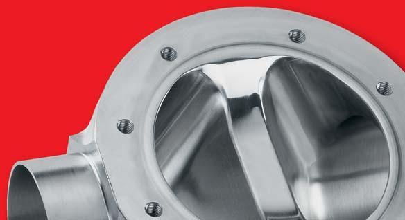
4 Description of use 2/2-way valve bodies 2/2-way straight through valve bodies are the body versions used most often in industrial applications. Butt weld spigots and clamp connections are the most common connections in sensitive sterile areas whereas threaded connections, aseptic flanges and threaded sockets only play a secondary role here. Features Standard valve body material in investment cast, forged or block material design and other materials on request Standard connections are butt weld spigots, clamps and sterile connections, other connections on request Internal surface contour mechanically polished and/or electropolished down to Ra 0.25 μm Compact design, GMP-compliant design Available with manual, pneumatic or motorized operators (modular system) 4

* * Material equivalency")
 42 1.4435 (BN2) Fe<0,5% F4 1.")
 43 1.")

5 Material selection 2/2-way valve bodies Investment casting Material code (BN2) Fe < 0.5% (ASTM A 351 CF3M)* * Material equivalency 316 L Forged body Material code (F316L) (BN2) Fe<0,5% F (F904L) Block material Material code (316L/F316L) (BN2) Fe<0,5% Other valve body materials , block material , titanium A , block material Hastelloy C 22 (NiCr21Mo14W) A3 Special materials on request 5
6 Grades of surface finish 2/2-way valve bodies Valve body surface finish, internal contour Forged body - s 40, 42, F4 Block material - s 41, 43 Investment casting s 32, 34 Ra 0,8 μm (30 μinch) for media wetted surfaces, mechanically polished internal X X 1502 Ra 0,8 μm (30 μinch) for media wetted surfaces, electropolished internal/external X Ra 0,6 μm (25 μinch) for media wetted surfaces, mechanically polished internal X 1 X Ra 0,6 μm (25 μinch) for media wetted surfaces, electropolished internal/external X Ra 0,25 μm (10 μinch) for media wetted surfaces, electropolished internal/external X Ra 0,25 μm (10 μinch) for media wetted surfaces, mechanically polished internal X Ra 0,4 μm (15 μinch) for media wetted surfaces, mechanically polished internal X Ra 0,4 μm (15 μinch) for media wetted surfaces, electropolished internal/external X Ra 0,5 μm (20 μinch) for media wetted surfaces, mechanically polished internal X Ra 0,5 μm (20 μinch) for media wetted surfaces, electropolished internal/external X Ra 0,4 μm (15 μinch) for media wetted surfaces, electropolished internal/external X Ra acc. to DIN 4768; at defined reference points. 1 For pipe inside diameter< 6 mm, the surface inside the spigot is Ra 0.8 μm. Modern, ergonomically shaped workstations and trained polishing staff give us the ability to provide high quality surface finishes. Depending on the required application, surface finishes from Ra 0.8 μm down to 0.25 μm can be achieved by polishing, electro polishing or a special process, we call elysieren. Mechanical hand polishing is carried out at our works to ensure our high quality standard. GEMÜ DE GEMÜ US DIN ASME BPE (2014) Ra μm Ra max μinch Hygiene class Ra μm Designation Ra max μinch Ra μm - converted H3 0.8 SF HE3c SF SF HE4c 0.4 SF H4 0.4 SF H HE5c 0.25 SF
7 Butt weld connections 2/2-way valve bodies Dimensions in mm DIN DIN DIN EN ISO Series 0 / Series 1 / Series 2 / Series 3 / Series A Series B / A 1B 60 JIS-G JIS-G SMS BS ASME BPE 59 ANSI/ ASME B36.19M 10s 63 ANSI/ ASME B36.19M 40s 65 MG DN NPS ød s ød s ød s ød s ød s ød s ød s ød s ød s ød s ød s ød s ød s ød s ¼" ⅜" ½" ⅜" ½" ¾" ½" ¾" " ¼" ½" " ½" " " MG = diaphragm size * only for investment cast body The angles of rotation for installation can be seen from the connection drawings on the following pages. The difference between tube specifications (Example DN 15) JIS 3459 ød = 21.7 s = 2.1 ISO ød = 21.3 s = 1.6 DIN Series 0 ød = 18 s = 1.5 DIN Series 1 ød = 18 s = 1.0 DIN Series 2 ød = 19 s = 1.5 DIN Series 3 ød = 20 s = 2.0 BS-OD Tubing ød = 12.7 s = 1.2 ASME BPE ød = 12.7 s = 1.65 ø d s 7


8 Selection of operators 2/2-way valve bodies Manually operated Type GEMÜ 9601 GEMÜ 9602 GEMÜ 9612 GEMÜ 9673 GEMÜ 9653 GEMÜ 9654 Material Stainless steel, plastic handwheel, with optical position indicator and seal adjuster Stainless steel, with optical position indicator and seal adjuster Stainless steel, plastic handwheel, with optical position indicator and seal adjuster Stainless steel, plastic handwheel, with optical position indicator and seal adjuster Stainless steel, plastic handwheel, with optical position indicator, stroke limiter and seal adjuster, lockable, optional: electrical position indicator Stainless steel, with optical position indicator, stroke limiter and seal adjuster, lockable, optional: electrical position indicator Autoclavable Operating temperature* -10 to 150 C -10 to 150 C -10 to 150 C -10 to 150 C -10 to 150 C -10 to 150 C Operating pressure* 0 to 10 bar 0 to 10 bar 0 to 10 bar 0 to 10 bar 0 to 10 bar 0 to 10 bar DN Diaphragm size Diaphragm size Diaphragm size Diaphragm size Diaphragm size Diaphragm size Diaphragm size * dependent on diaphragm material, see technical datasheet Elastomer diaphragms EPDM PTFE diaphragms PTFE/EPDM, PTFE/FPM 8


9 Pneumatically operated GEMÜ 9605 GEMÜ 9625 GEMÜ 9687 GEMÜ 9650 GEMÜ 9650TL GEMÜ 9651 GEMÜ 9658/9688 GEMÜ 9660 Plastic, with stainless steel distance piece, optical position indicator Plastic, with stainless steel distance piece, optical position indicator Plastic, with stainless steel distance piece, optical position indicator Stainless steel, with optical position indicator, optionally autoclavable Safety valve, stainless steel, mounting facility for proximity switches Stainless steel, with integrated automation module Two stage actuator, stainless steel Filling valve, stainless steel with optical position indicator, stroke limiter and seal adjuster (DN 4-25) to 150 C -10 to 150 C -10 to 150 C -10 to 150 C -10 to 150 C -10 to 150 C -10 to 150 C -10 to 150 C 0 to 8 bar 0 to 6 bar 0 to 10 bar 0 to 10 bar 0 to 8 bar 0 to 10 bar 0 to 10 bar 0 to 5 bar Valve body versions 2/2-way body investment casting 2/2-way version to all international standard butt weld connections 2/2-way body forged version 2/2-way version to all international standard butt weld connections Connections Clamps to all common standards Aseptic clamps to all common standards Aseptic unions to all common standards Aseptic flanges to all common standards Other versions and accessories available. See "Stainless Steel Diaphragm Valves" brochure. 9


10 Selection of operators 2/2-way valve bodies Pneumatically operated Motorized Type GEMÜ 9615 GEMÜ 9695 GEMÜ 9618 GEMÜ 9698 Material Plastic, with optical position indicator, only for 2/2-way valve bodies Plastic, with optical position indicator, only for 2/2-way valve bodies Plastic, with/without stainless steel distance piece, with optical position indicator Autoclavable Plastic, with stainless steel distance piece, with optical position indicator and manual override Operating temperature* -10 to 80 C -10 to 80 C 0 to 130 C (without distance piece -10 to 150 C 15 to 50 C) Operating pressure* 0 to 6 bar 0 to 10 bar 0 to 6 bar 0 to 6 bar DN 10 to to Supply voltage VAC, 120 VAC, 230 VAC, 50/60Hz Diaphragm size Diaphragm size Diaphragm size Diaphragm size Diaphragm size Diaphragm size Diaphragm size * dependent on diaphragm material 24 VAC, 120 VAC, 230 VAC, 50/60Hz 10
11 Butt weld spigots for EN ISO 1127 pipes, code (ASTM A 351 CF3M)* (F316L) forged body (F904L) F4 * Material equivalency 316 L EN ISO 1127, code 60 Angle of rotation α L LS H1* H1** f* øg* ød s A x B MG DN NPS /ø LK 34 40, F4 [mm] [mm] [mm] [mm] [mm] [mm] [mm] [mm] [mm] α α 8 8 ¼" x ⅜" x ½" ½" ¾" x " ¼" x ½" " x ½" x " " ø MG: Diaphragm size f*, øg*: only on investment cast body; H1*: investment cast body, H1** forged body The availability of the valve bodies depends on the valve body material and the nominal size. If a body is available, the angle of rotation α is indicated in the coloured columns. The angle of rotation is necessary for optimum draining of the body. 11
12 Butt weld spigots for DIN pipes, code (ASTM A 351 CF3M)* (F316L) forged body (F904L) F4 * Material equivalency 316 L DIN, code 0 MG DN NPS 4 - Angle of rotation α L LS H1* H1** f* øg* ød s A x B 34 40, F4 [mm] [mm] [mm] [mm] [mm] [mm] [mm] [mm] [mm] α α x ¼" ½" x ½" ¾" x " ¼" x ½" " x MG: Diaphragm size f*, øg*: only on investment cast body; H1*: investment cast body. H1** forged body The availability of the valve bodies depends on the valve body material and the nominal size. If a body is available, the angle of rotation α is indicated in the coloured columns. The angle of rotation is necessary for optimum draining of the body. 12
13 Butt weld spigots for DIN pipes, series 1, code (ASTM A 351 CF3M)* (F316L) forged body (F904L) F4 * Material equivalency 316 L DIN series 1, code 16 Angle of rotation α L LS H1* H1** f* øg* ød s A x B MG DN NPS 34 40, F4 [mm] [mm] [mm] [mm] [mm] [mm] [mm] [mm] [mm] α α 8 10 ⅜" x ⅜" x ½" ½" ¾" x " ¼" x ½" " x MG: Diaphragm size f*, øg*: only on investment cast body; H1*: investment cast body, H1** forged body The availability of the valve bodies depends on the valve body material and the nominal size. If a body is available, the angle of rotation α is indicated in the coloured columns. The angle of rotation is necessary for optimum draining of the body. 13
14 Butt weld spigots for DIN pipes, series 2, code 17; DIN 11866, series A, code 1A (ASTM A 351 CF3M)* (F316L) forged body (F904L) F4 * Material equivalency 316 L DIN series 2, code 17; DIN 11866, series A, code 1A Angle of rotation α L LS H1* H1** f* øg* ød s A x B MG DN NPS /ø LK 34 40, F4 [mm] [mm] [mm] [mm] [mm] [mm] [mm] [mm] [mm] α α 8 10 ⅜" x ⅜" x ½" ½" ¾" x " ¼" x ½" " x ½" x " " ø MG: Diaphragm size f*, øg*: only on investment cast body; H1*: investment cast body, H1** forged body The availability of the valve bodies depends on the valve body material and the nominal size. If a body is available, the angle of rotation α is indicated in the coloured columns. The angle of rotation is necessary for optimum draining of the body. 14
15 Butt weld spigots for DIN pipes, series 3, code (ASTM A 351 CF3M)* (F316L) forged body (F904L) F4 * Material equivalency 316 L DIN series 3, code 18 Angle of rotation α L LS H1* H1** f* øg* ød s A x B MG DN NPS 34 40, F4 [mm] [mm] [mm] [mm] [mm] [mm] [mm] [mm] [mm] α α 8 10 ⅜" x ⅜" x ½" ½" ¾" x " ¼" x ½" " x MG: Diaphragm size f*, øg*: only on investment cast body; H1*: investment cast body, H1** forged body The availability of the valve bodies depends on the valve body material and the nominal size. If a body is available, the angle of rotation α is indicated in the coloured columns. The angle of rotation is necessary for optimum draining of the body. 15
16 Butt weld spigots for ASME BPE pipes, code (ASTM A 351 CF3M)* (F316L) forged body (F904L) F4 * Material equivalency 316 L ASME BPE, code 59 MG DN NPS 8 ¼" Angle of rotation α L LS H1* H1** f* øg* ød s A x B /ø LK 34 40, F4 [mm] [mm] [mm] [mm] [mm] [mm] [mm] [mm] [mm] α α ⅜" x ½" ⅜" ½" x ¾" ¾" x " ½" x " x ½" x " " ø MG: Diaphragm size f*, øg*: only on investment cast body; H1*: investment cast body, H1** forged body The availability of the valve bodies depends on the valve body material and the nominal size. If a body is available, the angle of rotation α is indicated in the coloured columns. The angle of rotation is necessary for optimum draining of the body. 16
17 Butt weld spigots for BS 4825 pipes, code (ASTM A 351 CF3M)* (F316L) forged body (F904L) F4 * Material equivalency 316 L BS 4825, code 55 MG DN NPS 8 ¼" Angle of rotation α L LS H1* H1** f* øg* ød s A x B 34 40, F4 [mm] [mm] [mm] [mm] [mm] [mm] [mm] [mm] [mm] α α ⅜" x ½" ⅜" ½" x ¾" ¾" x MG: Diaphragm size f*, øg*: only on investment cast body; H1*: investment cast body, H1** forged body The availability of the valve bodies depends on the valve body material and the nominal size. If a body is available, the angle of rotation α is indicated in the coloured columns. The angle of rotation is necessary for optimum draining of the body. 17
18 Butt weld spigots for JIS-G 3447 pipes, code (ASTM A 351 CF3M)* (F316L) forged body (F904L) F4 * Material equivalency 316 L JIS-G 3447, code 35 Angle of rotation α L LS H1* H1** f* øg* ød s A x B MG DN NPS /ø LK 34 40, F4 [mm] [mm] [mm] [mm] [mm] [mm] [mm] [mm] [mm] α α " x ¼" x ½" " x ½" x " " ø MG: Diaphragm size f*, øg*: only on investment cast body; H1*: investment cast body, H1** forged body The availability of the valve bodies depends on the valve body material and the nominal size. If a body is available, the angle of rotation α is indicated in the coloured columns. The angle of rotation is necessary for optimum draining of the body. 18
19 Butt weld spigots for JIS-G 3459 pipes, code (ASTM A 351 CF3M)* (F316L) forged body (F904L) F4 * Material equivalency 316 L JIS-G 3459, code 36 MG DN NPS 8 Angle of rotation α L LS H1* H1** f* øg* ød s A x B /ø LK 34 40, F4 [mm] [mm] [mm] [mm] [mm] [mm] [mm] [mm] [mm] α α x 22 8 ¼" ⅜" x ½" ½" ¾" x " ¼" x ½" " x ½" x " " ø MG: Diaphragm size f*, øg*: only on investment cast body; H1*: investment cast body, H1** forged body The availability of the valve bodies depends on the valve body material and the nominal size. If a body is available, the angle of rotation α is indicated in the coloured columns. The angle of rotation is necessary for optimum draining of the body. 19
20 Butt weld spigots for SMS 3008 pipes, code (ASTM A 351 CF3M)* (F316L) forged body (F904L) F4 * Material equivalency 316 L SMS 3008, code 37 Angle of rotation α L LS H1* H1** f* øg* ød s A x B MG DN NPS /ø LK 34 40, F4 [mm] [mm] [mm] [mm] [mm] [mm] [mm] [mm] [mm] α α " x ¼" x ½" " x ½" x " " ø MG: Diaphragm size f*, øg*: only on investment cast body; H1*: investment cast body, H1** forged body The availability of the valve bodies depends on the valve body material and the nominal size. If a body is available, the angle of rotation α is indicated in the coloured columns. The angle of rotation is necessary for optimum draining of the body. 20
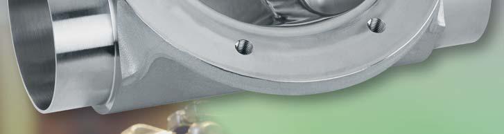
21 Clamp bodies All clamp connections are machined according to the spigot dimensions e.g. to DIN 11850, SMS 3008 or ASME BPE. We ask our customers to state which version or standard the connections shall comply with. Depending on the version, clamps are machined from the solid forged body or welded on. Investment cast bodies have welded on clamps as standard. Welding is carried out by specially qualified and certified welders utilising state-of-the art welding technology. In principle, special connections requested by customers can be provided on GEMÜ butt weld spigot bodies. Thus it is also possible to have different connections on one body. Clamp connections for forged 2/2-way bodies See page Clamps ASME BPE for ASME BPE pipes, short design Clamps following ASME BPE for EN ISO 1127 pipes, length EN 558-1, series Clamps ASME BPE for ASME BPE pipes, length EN 558-1, series Clamps DIN for DIN pipes, length EN 558-1, series 7 8A 25 Clamps SMS 3017 for SMS 3008 pipes, length EN 558-1, series 7 8E 26 Clamps IDF/ISO for JIS-G 3447 pipes, length EN 558-1, series 7 8F 27 Clamps IDF/ISO for JIS-G 3459 pipes, length EN 558-1, series 7 8H 28 Other clamp connections on request 21
22 Clamps ASME BPE for ASME BPE pipes, short design, code (F316L) forged body (F904L) F4 ASME BPE for ASME BPE pipes, short design, code 80 MG DN NPS 8 ¼" L H1 ød1 ød3 A x B /ø LK [mm] [mm] [mm] [mm] [mm] α 4.57 Angle of rotation α 40, F ⅜" x ½" ½" x ¾" ¾" x " ½" x " x ½" x " " ø MG: Diaphragm size 22
23 Clamps following ASME BPE for EN ISO 1127 pipes, code (F316L) forged body (F904L) F4 ASME BPE for EN ISO 1127 pipes, length EN series 7, code 82 L H1 ød1 ød3 A x B /ø LK MG DN NPS [mm] [mm] [mm] [mm] [mm] α 8 8 ¼" x Angle of rotation α 40, F ⅜" x ½" ½" ¾" x " ¼" x ½" " x ½" x " " ø MG: Diaphragm size 23
24 Clamps ASME BPE for ASME BPE pipes, code (F316L) forged body (F904L) F4 ASME BPE for ASME BPE pipes, length EN series 7, code 88 L H1 ød1 ød3 A x B /ø LK MG DN NPS [mm] [mm] [mm] [mm] [mm] α 8 15 ½" x Angle of rotation α 40, F ½" x ¾" ¾" x " ½" x " x ½" x " " ø MG: Diaphragm size 24
25 Clamps DIN for DIN pipes, code 8A (F316L) forged body (F904L) F4 DIN for DIN pipes, length EN series 7, code 8A L H1 ød1 ød3 A x B /ø LK MG DN NPS [mm] [mm] [mm] [mm] [mm] α 8 10 ⅜" x Angle of rotation α 40, F ⅜" x ½" ½" ¾" x " ¼" x ½" " x ½" x " " ø MG: Diaphragm size 25
26 Clamps SMS 3017 for SMS 3008 pipes, code 8E (F316L) forged body (F904L) F4 SMS 3017 for SMS 3008 pipes, length EN series 7, code 8E L H1 ød1 ød3 A x B /ø LK MG DN NPS [mm] [mm] [mm] [mm] [mm] α " x Angle of rotation α 40, F ¼" x ½" " x ½" x " " ø MG: Diaphragm size 26
27 Clamps IDF/ISO for JIS-G 3447 pipes, code 8F (F316L) forged body (F904L) F4 IDF/ISO for JIS-G 3447 pipes, length EN series 7, code 8F L H1 ød1 ød3 A x B /ø LK MG DN NPS [mm] [mm] [mm] [mm] [mm] α " x Angle of rotation α 40, F ¼" x ½" " x ½" x " " ø MG: Diaphragm size 27
28 Clamps IDF/ISO for JIS-G 3459 pipes, code 8H (F316L) forged body (F904L) F4 IDF/ISO for JIS-G 3459 pipes, length EN series 7, code 8H L H1 ød1 ød3 A x B /ø LK MG DN NPS [mm] [mm] [mm] [mm] [mm] α 8 8 ¼" x Angle of rotation α 40, F ⅜" x ½" ½" x MG: Diaphragm size 28
29 Clamp ASME BPE (short design), code 80 - butt weld spigot ASME BPE, code (F316L) forged body (F904L) F4 Clamp ASME BPE (short design), code 80 - butt weld spigot ASME BPE, code 59 MG DN NPS 8 L LS H1 ød1 ød3 ød s A x B /ø LK [mm] [mm] [mm] [mm] [mm] [mm] [mm] [mm] α 8 ¼" ⅜" x ½" Angle of rotation α 40, F ½" x ¾" ¾" x " ½" x " x ½" x " " ø MG: Diaphragm size 29
30 Clamp ASME BPE, length EN series 7, code 82 - butt weld spigot EN ISO 1127, code (F316L) forged body (F904L) F4 Clamp ASME BPE, length EN series 7, code 82 - butt weld spigot EN ISO 1127, code 60 L LS H1 ød1 ød3 ød s A x B /ø LK MG DN NPS [mm] [mm] [mm] [mm] [mm] [mm] [mm] [mm] α 8 8 ¼" x Angle of rotation α 40, F ⅜" x ½" ½" ¾" x " ¼" x ½" " x ½" x " " ø MG: Diaphragm size 30
31 Clamp ASME BPE, length EN series 7, code 88 - butt weld spigot ASME BPE, code (F316L) forged body (F904L) F4 Clamp ASME BPE, length EN series 7, code 88 - butt weld spigot ASME BPE, code 59 L LS H1 ød1 ød3 ød s A x B /ø LK MG DN NPS [mm] [mm] [mm] [mm] [mm] [mm] [mm] [mm] α 8 15 ½" x Angle of rotation α 40, F ½" x ¾" ¾" x " ½" x " x ½" x " " ø MG: Diaphragm size 31
32 Clamp DIN 32676, code 8A - butt weld spigot DIN series 1, code (F316L) forged body (F904L) F4 Clamp DIN 32676, code 8A - butt weld spigot DIN series 1, code 16 L LS H1 ød1 ød3 ød s A x B /ø LK MG DN NPS [mm] [mm] [mm] [mm] [mm] [mm] [mm] [mm] α 8 10 ⅜" x Angle of rotation α 40, F ⅜" x ½" ½" ¾" x " ¼" x ½" " x MG: Diaphragm size 32
33 Clamp DIN 32676, code 8A - butt weld spigot DIN series 2, code (F316L) forged body (F904L) F4 Clamp DIN 32676, code 8A - butt weld spigot DIN series 2, code 17 L LS H1 ød1 ød3 ød s A x B /ø LK MG DN NPS [mm] [mm] [mm] [mm] [mm] [mm] [mm] [mm] α 8 10 ⅜" x Angle of rotation α 40, F ⅜" x ½" ½" ¾" x " ¼" x ½" " x ½" x " " ø MG: Diaphragm size 33
34 Clamp DIN 32676, code 8A - butt weld spigot DIN series 3, code (F316L) forged body (F904L) F4 Clamp DIN 32676, code 8A - butt weld spigot DIN series 3, code 18 L LS H1 ød1 ød3 ød s A x B /ø LK MG DN NPS [mm] [mm] [mm] [mm] [mm] [mm] [mm] [mm] α 8 10 ⅜" x Angle of rotation α 40, F ⅜" x ½" ½" ¾" x " ¼" x ½" " x MG: Diaphragm size 34
35 Clamp IDF/ISO for JIS-G 3447 pipes, code 8F - butt weld spigot JIS-G 3447, code (F316L) forged body (F904L) F4 Clamp IDF/ISO for JIS-G 3447 pipes, code 8F - butt weld spigot JIS-G 3447, code 35 L LS H1 ød1 ød3 ød s A x B /ø LK MG DN NPS [mm] [mm] [mm] [mm] [mm] [mm] [mm] [mm] α " x Angle of rotation α 40, F ¼" x ½" " x ½" x " " ø MG: Diaphragm size 35
36 Clamp IDF/ISO for JIS-G pipes, code 8H - butt weld spigot JIS-G 3459, code (F316L) forged body (F904L) F4 Clamp IDF/ISO for JIS-G pipes, code 8H - butt weld spigot JIS-G 3459, code 36 L LS H1 ød1 ød3 ød s A x B /ø LK MG DN NPS [mm] [mm] [mm] [mm] [mm] [mm] [mm] [mm] α 8 8 ¼" x Angle of rotation α 40, F ⅜" x ½" ½" x MG: Diaphragm size 36
37 Clamp SMS 3017, length EN series 7, code 8E - butt weld spigot SMS 3008, code (F316L) forged body (F904L) F4 Clamp SMS 3017, length EN series 7, code 8E - butt weld spigot SMS 3008, code 37 L LS H1 ød1 ød3 ød s A x B /ø LK MG DN NPS [mm] [mm] [mm] [mm] [mm] [mm] [mm] [mm] α " x Angle of rotation α 40, F ¼" x ½" " x ½" x " " ø MG: Diaphragm size 37


38 Aseptic clamps Aseptic clamping connections to DIN A complement the existing clamping connection options. Either grooved clamps or notched clamps are welded onto the base of the DIN or ISO butt weld spigot body on both sides. If the valve is to have a grooved clamp on one side and a notched clamp on the other side, this is defined by the corresponding code. Other types of connection, such as the combination of an aseptic clamp and butt weld spigot, are possible in principle and are each individually defined depending on requirements. Aseptic clamping connection DIN A Pipe DIN ISO Grooved aseptic clamp on both sides E1 E4 Notched aseptic clamp on both sides E2 E5 One side grooved aseptic clamp, other side notched aseptic clamp E3 E6 38


39 Dairy pipe and aseptic unions The dairy pipe union to DIN and the aseptic pipe union to DIN A are also standard connections. If the valve is to have a threaded spigot at one connection and a conical coupling or liner with union nuts at the other side, this is defined by the corresponding code. Furthermore, other versions customary on the market can also be adapted. Unions to DIN Aseptic pipe union DIN A Threaded spigot on both sides 6 Threaded spigot on one side, cone spigot with union nut on the other side 62 Pipe DIN ISO Aseptic threaded spigot on both sides C1 C4 Aseptic union with union nut on both sides C2 C5 One side aseptic threaded spigot, other side aseptic union with union nut C3 C6 39


40 Aseptic flanges Aseptic flanges to DIN A complement the existing standard connection options. Either grooved flanges or loose flanges are welded onto the base of the DIN or ISO butt weld spigot body on both sides. If the valve is to have a grooved flange at one connection and a loose flange at the other side, this is defined by the corresponding code. Other connections, such as the combination of an aseptic flange and butt weld spigot, are possible in principle and are each individually defined depending on requirements. Aseptic flange connection DIN A Pipe DIN ISO Grooved aseptic flange on both sides A1 A4 Loose aseptic flange on both sides A2 A5 One side grooved aseptic flange, other side loose aseptic flange A3 A6 40
41 Kv value Kv value In order to be able to compare the extremely varied geometries, valve designs and nominal sizes of different equipment and valves, they are always tested and measured under the same conditions. As a result of test conditions such as these, a flow rate that is specific to each valve is obtained and this flow rate can also serve as a calculation basis for planning a plant, for example. The Kvs values stated below are only valid for 2/2-way valves. Kvs value The Kvs value is the Kv value when the valve is fully open (100%). The Kvs value (nominal flow coefficient) corresponds to the Kv100 value with a tolerance of ±10% (to DIN EN 60534). Medium: Water (H 2 O) Temperature: 5 to 30 C Flow rate: The differential pressure Δp between the pressure input and pressure output side is 1 bar. Measurement unit: measured in m 3 /h Cv value: measured in US gallons per minute, at a differential pressure Δp of 1 PSI with water. 1 Cv = 1.17 x Kv 1 Kv = 0.86 x Cv Diaphragm size Diaphragm size 8 Diaphragm size 10 Diaphragm size 25 DN Size Butt weld spigots according to pipe standard DIN DIN Series 1 DIN Series 2 DIN Series 3 SMS3008 ASME BPE EN ISO Kvs [m³/h] Kvs [m³/h] Kvs [m³/h] Kvs [m³/h] Kvs [m³/h] Kvs [m³/h] Kvs [m³/h] 4 ⅛" / 6 " ¼" ⅜" ½" ⅜" ½" ¾" ½" ¾" " Diaphragm 32 1¼" size ½" Diaphragm size " Diaphragm 65 2½" size " Diaphragm size " Notes: For BS 4825 ( 55) the Kvs values are the same or slightly higher than ASME BPE as the pipe internal diameters are almost identical. For JIS-G 3459 ( 36) the Kvs values are the same or slightly lower than EN ISO 1127 as the pipe internal diameters are almost identical. Kvs values for clamp connections always refer to the corresponding pipe standard. Kvs values were determined with water at 20 C, P1 = 6bar, P2 = 5bar, EPDM 13 diaphragm, tolerance ± 10%. Kvs values for PTFE diaphragms may be lower especially at lower operating pressures as the material is stiffer. The operating pressure influences the Kvs value. 41
 with clamp connection and butt weld spigot: Type Nominal")
 with clamp connections: Type Nominal size DN 1 Body configuration Connection DN 1 Nominal size DN 2 Connection DN 2 A B C D E G H K K600 25 D 88 40 1507")
42 Order code - 2/2-way bodies Order example for 2/2-way bodies (diaphragm size 8) with butt weld spigots: Type Nominal size DN 1 Body configuration Connection DN 1 Nominal size DN 2 Connection DN 2 A B C D E G H K K D Additional data Order example for 2/2-way bodies (diaphragm size 10) with clamp connection and butt weld spigot: Type Nominal size DN 1 Body configuration Connection DN 1 Nominal size DN 2 Connection DN 2 A B C D E G H K K D Additional data Order example for 2/2-way bodies (from diaphragm size 25) with clamp connections: Type Nominal size DN 1 Body configuration Connection DN 1 Nominal size DN 2 Connection DN 2 A B C D E G H K K D Additional data 42


43 Angle of rotation for optimum draining In the pharmaceutical and biotechnological industries and other sensitive industrial sectors the drainability and cleanability of plant plays an important role. Very often plants are cleaned and sterilised after every production process. The objective is to keep the residue as low as possible in order to optimise the sterilisation and cleaning processes of plant and piping systems. In specialist literature and documents from plant constructors and valve manufacturers the term self-draining is often used in this context. It is a ficticious term for the independent emptying of a vessel and/or a pipe section through an opened valve. Depending on a variety of factors it is however not normally possible to expect full drainage without leaving residue even with vertical piping. Therefore the term self-draining is often used incorrectly. The term free outlet, unhindered outlet or optimum draining is more realistic. At GEMÜ we use the term optimum draining. Optimum drainability of a valve depends on several factors: Design of the internal geometry of the valve body Different pipe standards (ISO, DIN, SMS, ASME BPE, JIS etc.), as they have different inside diameters at the same nominal size Installation position in the pipeline with regard to horizontal rotation and vertical inclination Viscosity and adhesive qualities of the medium/media Diaphragm valves offer the best structural conditions for an unhindered outlet of the working medium when the valve is open. In an ideal case, the pipe and the valve are vertical. However, if the pipe is horizontal, the valve must be turned axially in the pipe until the outermost point of the sealing weir corresponds to the lowest point of the connecting pipe. Thus the working medium can optimally flow around the weir. The only way to gain the necessary viewing point to set the rotation angle is to remove the operator (manual bonnet or actuator) prior to installing the valve. Optical alignment is often sufficient it must be noted, however, that the eyes of the viewer must be in line with the transition of the weir and the lowest point of the pipe. Dependent on the viscosity of the working medium or the required outlet velocity, the pipe runs should have a corresponding gradient (pipe inclination). GEMÜ has calculated draining angles for the various nominal sizes and pipe standards in order to facilitate installation of valves for optimised draining. The draining angles mentioned are valid for installation in horizontal pipe systems. The GEMÜ angle α is quoted from when the valve is lying on its side with a vertical weirplate and the rotation angle is UPWARDS. Please note the drawing. (Attention: Other manufacturers quote the angle using a horizontal weirplate from the vertical centreline downwards). The draining angles mentioned in this brochure are valid for valve bodies produced in the EU. Please contact your local supplier for further information. The values of the draining angles are only provided as a guide without tolerances. Drainability in a plant is the responsibility of the plant designer, plant constructor and end user due to factors described previously. 43

44 GEMÜ angle gauge Angle scale setting range ± 65 Angle indicator with spirit level Angle indicator locking screw Location spigot with eccentric cam Base plate Indication of valve body fl ow direction Diaphragm size identifi cation 2 rigid location spigots GEMÜ has developed a patented angle gauge to simplify mounting 2/2-way stainless steel diaphragm valve bodies. The angle gauge enables quick and simple determination of the correct mounting position of a diaphragm valve body. The angle gauge is placed on the valve body so that its location spigots engage in the holes intended for actuator fixing. It is then locked by an eccentric cam at one of the location spigots. The flow direction is clearly identified to prevent incorrect positioning. The correct installation angle, dependent on the valve body type, is indicated in this brochure. The given angle is set on the angle gauge. The valve body is rotated until the spirit is level. Then the body can be installed in the piping. The angle gauge is available for diaphragm sizes MG Please use the article numbers listed below when ordering: Angle gauge for diaphragm size 8: Angle gauge for diaphragm size 10: Angle gauge for diaphragm size 25: Angle gauge for diaphragm size 40: Angle gauge for diaphragm size 50: Angle gauge for diaphragm size 80: Angle gauge for diaphragm size 100:


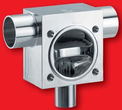
45 Description of use T valve bodies Seal system T valve bodies are preferably welded into ring mains with the outlet in a vertical direction. This allows the working medium to be drawn off or fed almost deadleg free. Features EHEDG-certified GEMÜ seal system Made from block material, no welds in the media wetted area (i. e. reduction of validation times) Compact design, GMP-compliant design Grades of surface finish: Internal contour mechanically polished and/or electropolished down to Ra 0.25 μm Standard valve body material (316L), other materials on request Standard connections are butt weld spigots, clamps and sterile connections, other connections on request Available with manual, pneumatic or motorized operators 45
* * Material equivalency 316 L Block material Material code 41 1.4435 (316L) 43 1.4435 (BN2) Fe < 0.")


46 Material selection T valve bodies Investment casting Material code (BN2) Fe < 0.5% (ASTM A 351 CF3M)* * Material equivalency 316 L Block material Material code (316L) (BN2) Fe < 0.5% Connections Butt weld spigots DIN 0 Butt weld spigots DIN 11850, series 1 16 Butt weld spigots DIN 11850, series 2 17 Butt weld spigots DIN 11866, series A 1A Butt weld spigots DIN 11866, series B 1B Butt weld spigots JIS-G Butt weld spigots JIS-G Butt weld spigots SMS Butt weld spigots ASME BPE 59 Butt weld spigots EN ISO Main pipe* DN 2 Branch* DN Diaphragm size *More combinations main pipe-branch possible on request For valve types Specifications see brochure "Stainless Steel Diaphragm Valves" 46
47 Grades of surface finish T valve bodies Valve body surface finish, internal contour Forged body - s 40, 42, F4 Block material - s 41, 43 Investment casting s 32, 34 Ra 0.8 μm, mechanically polished internal, blasted external X X 1502 Ra 0.8 μm, electropolished internal/external X Ra 0.6 μm, mechanically polished internal, blasted external X 1 X Ra 0.6 μm, electropolished internal/external X Ra 0.4 μm, mechanically polished internal, blasted external X Ra 0.4 μm, electropolished internal/external X Ra 0.25 μm, mechanically polished internal, blasted external X Ra 0.25 μm, electropolished internal/external X Ra acc. to DIN 4768; at defined reference points. Surface finish data refers to media wetted surfaces. 1 Not possible for connections DN 8 codes 55 and 59, DN 4 code 0 as well as all other connections < 6 mm. GEMÜ DE GEMÜ US DIN ASME BPE (2014) Ra μm Ra max μinch Hygiene class Ra μm Designation Ra max μinch Ra μm - converted H3 0.8 SF HE3c SF SF HE4c 0.4 SF H4 0.4 SF H HE5c 0.25 SF


 and is provided")


48 T valve bodies for sampling Body version "A" Dimension example for diaphragm size mm at d<6mm This particular design is used to take samples from large ring mains ( DN 50). A very good deadleg ratio is achieved as a result of the optimized contour. In comparison to the ring main cross section, the outlet branch has a small nominal size ( DN 15) and is provided with a diaphragm valve with a diaphragm size of 8 or 10. Features Cavity fully shaped, deadleg ratio < 1 x D Compact design Optimal draining if installed at an angle 48
49 T valve bodies for EN ISO 1127 pipes, DN 6 - DN (BN2) Fe<0,5% (ASTM A 351 CF3M)* (316L/F316L) (BN2) Fe<0,5% 43 * Material equivalency 316 L Special materials on request The valve body dimensions for your order are clearly defi ned by specifi cation of the codes in the fi elds with a coloured background in the given sequence. Note: Dimensions code 32 = dimensions code 34 Dimensions code 41 = dimensions code 43 Dimensions DN DN MG 2 WKZ 3 D1 S1 D2 S * L L1 L2 L3 H H1 H2 B B1 G 4 (kg) Other combinations on request ¹ see Butt weld spigots table on page 7, ² MG = diaphragm size, ³ WKZ = valve body material code, ⁴ G = valve body weight. * Attention: The external geometry does not correspond to the drawing shown. Note: Dimensions for code 1B (DIN series B) correspond to code 60. Continued on the next page 49
50 T valve bodies for EN ISO 1127 pipes, DN 6 - DN (BN2) Fe<0,5% (ASTM A 351 CF3M)* (316L/F316L) (BN2) Fe<0,5% 43 * Material equivalency 316 L Special materials on request The valve body dimensions for your order are clearly defi ned by specifi cation of the codes in the fi elds with a coloured background in the given sequence. Note: Dimensions code 32 = dimensions code 34 Dimensions code 41 = dimensions code 43 Dimensions DN DN MG 2 WKZ 3 D1 S1 D2 S L L1 L2 L3 H H1 H2 B B1 G 4 (kg) Other combinations on request ¹ see Butt weld spigots table on page 7, ² MG = diaphragm size, ³ WKZ = valve body material code, ⁴ G = valve body weight. * Attention: The external geometry does not correspond to the drawing shown. Note: Dimensions for code 1B (DIN series B) correspond to code 60. Continued on the next page 50
51 Dimensions DN DN MG 2 WKZ 3 D1 S1 D2 S L L1 L2 L3 Other combinations on request ¹ see Butt weld spigots table on page 7, ² MG = diaphragm size, ³ WKZ = valve body material code, ⁴ G = valve body weight. * Attention: The external geometry does not correspond to the drawing shown. Note: Dimensions for code 1B (DIN series B) correspond to code 60. H H1 H2 B B1 G 4 (kg) 51
52 T valve bodies for DIN pipes, DN 6 - DN (BN2) Fe<0,5% (ASTM A 351 CF3M)* (316L/F316L) (BN2) Fe<0,5% 43 * Material equivalency 316 L Special materials on request The valve body dimensions for your order are clearly defi ned by specifi cation of the codes in the fi elds with a coloured background in the given sequence. Note: Dimensions code 32 = dimensions code 34 Dimensions code 41 = dimensions code 43 Dimensions DN DN MG 2 WKZ 3 D1 S1 D2 S * * L L1 L2 L3 H H1 H2 B B1 G 4 (kg) Other combinations on request ¹ see Butt weld spigots table on page 7. ² MG = diaphragm size. ³ WKZ = valve body material code. ⁴ G = valve body weight. * Attention: The external geometry does not correspond to the drawing shown. Continued on the next page 52
53 Dimensions DN DN MG 2 WKZ 3 D1 S1 D2 S L L1 L2 L3 H H1 H2 B B1 G 4 (kg) Other combinations on request ¹ see Butt weld spigots table on page 7. ² MG = diaphragm size. ³ WKZ = valve body material code. ⁴ G = valve body weight. * Attention: The external geometry does not correspond to the drawing shown. Continued on the next page 53
54 T valve bodies for DIN pipes, DN 6 - DN (BN2) Fe<0,5% (ASTM A 351 CF3M)* (316L/F316L) (BN2) Fe<0,5% 43 * Material equivalency 316 L Special materials on request The valve body dimensions for your order are clearly defi ned by specifi cation of the codes in the fi elds with a coloured background in the given sequence. Note: Dimensions code 32 = dimensions code 34 Dimensions code 41 = dimensions code 43 Dimensions DN DN MG 2 WKZ 3 D1 S1 D2 S Other combinations on request ¹ see Butt weld spigots table on page 7. ² MG = diaphragm size. ³ WKZ = valve body material code. ⁴ G = valve body weight. * Attention: The external geometry does not correspond to the drawing shown. Continued on the next page L L1 L2 L3 H H1 H2 B B1 G 4 (kg) 54
55 Dimensions DN DN MG 2 WKZ 3 D1 S1 D2 S L L1 L2 L3 Other combinations on request ¹ see Butt weld spigots table on page 7. ² MG = diaphragm size. ³ WKZ = valve body material code. ⁴ G = valve body weight. * Attention: The external geometry does not correspond to the drawing shown. H H1 H2 B B1 G 4 (kg) 55
56 T valve bodies for ASME - BPE pipes, DN 8 - DN (BN2) Fe<0,5% (ASTM A 351 CF3M)* (316L/F316L) (BN2) Fe<0,5% 43 * Material equivalency 316 L Special materials on request The valve body dimensions for your order are clearly defi ned by specifi cation of the codes in the fi elds with a coloured background in the given sequence. Note: Dimensions code 32 = dimensions code 34 Dimensions code 41 = dimensions code 43 Dimensions DN DN MG 2 WKZ 3 D1 S1 D2 S * Other combinations on request ¹ see Butt weld spigots table on page 7, ² MG = diaphragm size, ³ WKZ = valve body material code, ⁴ G = valve body weight. * Attention: The external geometry does not correspond to the drawing shown. L L1 L2 L3 H H1 H2 B B1 G 4 (kg) 56
57 Dimensions DN DN MG 2 WKZ 3 D1 S1 D2 S L L1 L2 L3 Other combinations on request ¹ see Butt weld spigots table on page 7, ² MG = diaphragm size, ³ WKZ = valve body material code, ⁴ G = valve body weight. * Attention: The external geometry does not correspond to the drawing shown. H H1 H2 B B1 G 4 (kg) 57
58 T valve bodies for JIS-G3447 pipes, DN 25 - DN (316L/F316L) (BN2) Fe<0,5% 43 The valve body dimensions for your order are clearly defi ned by specifi cation of the codes in the fi elds with a coloured background in the given sequence. Note: Dimensions code 41 = dimensions code 43 Dimensions DN DN MG 2 WKZ 3 D1 S1 D2 S Other combinations on request ¹ see Butt weld spigots table on page 7, ² MG = diaphragm size, ³ WKZ = valve body material code, ⁴ G = valve body weight. L L1 L2 L3 H H1 H2 B B1 G 4 (kg) 58
59 T valve bodies for JIS-G3459 pipes, DN 6 - DN (316L/F316L) (BN2) Fe<0,5% 43 The valve body dimensions for your order are clearly defi ned by specifi cation of the codes in the fi elds with a coloured background in the given sequence. Note: Dimensions code 41 = dimensions code 43 Dimensions DN DN 1 11 MG 2 WKZ 3 D1 S1 D2 S L L1 L2 L3 H H1 H2 B B1 G 4 (kg) Other combinations on request ¹ see Butt weld spigots table on page 7, ² MG = diaphragm size, ³ WKZ = valve body material code, ⁴ G = valve body weight. Continued on the next page 59
60 T valve bodies for JIS-G3459 pipes, DN 6 - DN (316L/F316L) (BN2) Fe<0,5% 43 The valve body dimensions for your order are clearly defi ned by specifi cation of the codes in the fi elds with a coloured background in the given sequence. Note: Dimensions code 41 = dimensions code 43 Dimensions DN DN 1 11 MG 2 WKZ 3 D1 S1 D2 S L L1 L2 L3 H H1 H2 B B1 G 4 (kg) Other combinations on request ¹ see Butt weld spigots table on page 7, ² MG = diaphragm size, ³ WKZ = valve body material code, ⁴ G = valve body weight. Continued on the next page 60
61 Dimensions DN DN 1 11 MG 2 WKZ 3 D1 S1 D2 S L L1 L2 L3 Other combinations on request ¹ see Butt weld spigots table on page 7, ² MG = diaphragm size, ³ WKZ = valve body material code, ⁴ G = valve body weight. H H1 H2 B B1 G 4 (kg) 61
62 T valve bodies for SMS 3008 pipes, DN 25 - DN (316L/F316L) (BN2) Fe<0,5% 43 The valve body dimensions for your order are clearly defi ned by specifi cation of the codes in the fi elds with a coloured background in the given sequence. Note: Dimensions code 41 = dimensions code 43 Dimensions DN DN MG 2 WKZ 3 D1 S1 D2 S L L1 L2 L3 H H1 H2 B B1 G 4 (kg) Other combinations on request ¹ see Butt weld spigots table on page 7, ² MG = diaphragm size, ³ WKZ = valve body material code, ⁴ G = valve body weight. Continued on the next page 62
63 Dimensions DN DN MG 2 WKZ 3 D1 S1 D2 S L L1 L2 L3 Other combinations on request ¹ see Butt weld spigots table on page 7, ² MG = diaphragm size, ³ WKZ = valve body material code, ⁴ G = valve body weight. H H1 H2 B B1 G 4 (kg) 63
64 T valve bodies with clamp connections Butt weld spigots Spigots DIN 11850, series 1 16 Spigots DIN 11850, series 2 17 Spigots DIN 11866, series A 1A Spigots SMS Spigots ASME BPE 59 Spigots EN ISO Clamp connections Clamps following ASME BPE for EN ISO 1127 pipes, clamp DN1 fully machined 8K Clamp following ASME BPE for EN ISO 1127 pipes 82 Clamps following DIN for EN ISO 1127 pipes, clamp DN1 fully machined 8L Clamps following DIN for EN ISO 1127 pipes 83 Clamps DIN for DIN pipes, clamp DN1 fully machined 8A Clamps DIN for pipes 86 DN 1 DN 2 Clamps SMS 3017 for SMS 3008 pipes 87 Clamps ASME BPE for ASME BPE pipes, clamp DN1 fully machined 80 Clamps ASME BPE for ASME BPE pipes 88 * see tables on pages Dimensions of clamp connections for T valve bodies For butt weld spigots , Clamp connections K 8L 8A 80 DN ødi1/ Di2 øc1/ C2 LC LK ødi1/ Di2 øc1/ C2 LC LK ødi1/ Di2 øc1/ C2 LC LK ødi1/ Di2 øc1/ C2 LC ødi1/ Di2 øc1/ C2 LC LK 64

 with clamp connection* at the branch: Type")


65 Order code - T bodies Order example for T valve bodies (diaphragm size 8, A version) with butt weld spigots: Type Nominal size DN 1 Body configuration Connection DN 1 Nominal size DN 2 Connection DN 2 A B C D E G H K K A Additional data Order example for T valve bodies (diaphragm size 10) with clamp connection* at the branch: Type Nominal size DN 1 Body configuration Connection DN 1 Nominal size DN 2 Connection DN 2 A B C D E G H K K T Additional data Order example for T valve bodies (from diaphragm size 25) with clamp connections*: Type Nominal size DN 1 Body configuration Connection DN 1 Nominal size DN 2 Connection DN 2 A B C D E G H K K T Additional data DN 1 = branch, DN 2 = main pipe * Unless otherwise indicated, the clamp connections are welded on (main pipe) or fully machined (branch). 65

66 Materials and certificates Type Designation of the test certificate in accordance with EN Content of the certificate Confirmation of the certificate by 2.1 Certificate of compliance with the order Confirmation of compliance with the order the manufacturer 2.2 Test report Confirmation of compliance with the order with specification of results of non-specific testing the manufacturer 3.1 Inspection certificate 3.1 Confirmation of compliance with the order with specification of results of specific testing the manufacturer acceptance officer independent of the production division 3.2 Inspection certificate 3.2 Confirmation of compliance with the order with specification of results of specific testing the manufacturer acceptance officer independent of the production division and the acceptance officer commissioned by the purchaser or the acceptance officer named in the official regulations The table above provides an overview of the possible certificates which are generally available. The type of certificate and its content must be specified exactly before ordering to be able to provide the required documents. Later requests of certificates may not be possible or possible only under certain conditions. Our specialists are happy to answer any questions you might have. 66
2/2-Way and T Valve Bodies in Stainless Steel
 2/2-Way and T Valve Bodies in Stainless Steel Leading the world in pharmaceutical and biotechnology industry sterilisation processes GEMÜ is one of the leading manufacturers of valves, measurement and
611, 671. Diaphragm Valve, Metal
 Distributed by: Tel: 905.677.9000 Toll Free: 1.0.486.7863 www.tricanada.com Diaphragm Valve, Metal Construction The 611 and 671 manually operated 2/2-way metal diaphragm valves have a low maintenance plastic
Diaphragm Valve, Metal
 Diaphragm Valve, Metal Construction The GEMÜ piston actuated 2/2-way diaphragm valve is designed for use in sterile areas of application. All metallic actuator components are made of stainless steel. The
Diaphragm Valve, Metal
 Diaphragm Valve, Metal Construction The GEMÜ pneumatically operated 2/2-way diaphragm valve has a low maintenance actuator. Normally Closed, Normally Open and Double Acting control functions are available.
Diaphragm Valve, Metal
 Diaphragm Valve, Metal Construction The 601, and manually operated diaphragm valves have a temperature resistant plastic handwheel, 602 has a stainless steel handwheel. Bonnet and internals are made all
611, 671. Diaphragm Valve, Metal
 Diaphragm Valve, Metal Construction The 611 and 671 manually operated 2/2-way metal diaphragm valves have a low maintenance plastic bonnet and an integral optical position indicator as standard. Features
Diaphragm Valve, Metal
 Distributed by: Tel: 905.677.9000 Toll Free: 1.800.486.7863 www.tricanada.com Diaphragm Valve, Metal Construction The GEMÜ 2/2-way diaphragm valve has a low maintenance piston actuator which can be controlled
Diaphragm Valve, Metal
 Diaphragm Valve, Metal Construction The GEMÜ 2/2-way diaphragm valve has a low maintenance piston actuator which can be controlled by inert gases. Normally Closed, Normally Open and Double Acting control
Diaphragm Valve, Metal
 Diaphragm Valve, Metal Construction The GEMÜ pneumatically operated 2/2-way diaphragm valve has a low maintenance piston actuator which can be controlled by inert gases. The valve has an integrated optical
653, 654. Diaphragm Valve, Metal
 Diaphragm Valve, Metal Construction The GEMÜ 653 / 654 manually operated 2/2-way metal diaphragm valve has a stainless steel bonnet and is available in two versions - GEMÜ 653 has a handwheel in high temperature
650TL. Diaphragm Valve, Metal. Special version "TL"
 Special version "TL" Diaphragm Valve, Metal Construction GEMÜ is a manual tapping valve with automatic closing function which is designed for use in sterile applications. This piston actuated diaphragm
Diaphragm Valve, Metal
 Diaphragm Valve, Metal Construction The GEMÜ motorized metal diaphragm valve has a low maintenance electric actuator and a reversible synchronous motor. It is operated via a reduction gear and cam. The
Diaphragm Valve, Metal
 Diaphragm Valve, Metal Construction The GEMÜ pneumatically operated 2/2-way diaphragm valve has a low maintenance membrane actuator which can be controlled by inert gaseous media. Normally Closed, Normally
650TL. Diaphragm Valve, Metal. Special version "TL"
 Special version "L" Diaphragm Valve, Metal Construction GEMÜ is a manual tapping valve with automatic closing function which is designed for use in sterile applications. his piston actuated diaphragm valve
Tank Bottom Valve, Metal
 Tank Bottom Valve, Metal Construction The 2/2-way metal tank bottom valve GEMÜ is manually operated with a side mounted gear which has an optical position indicator as standard. The stainless steel valve
Diaphragm Valve, Metal
 Diaphragm Valve, Metal Construction The GEMÜ motorized metal diaphragm valve has a low maintenance electric actuator and a reversible synchronous motor. It is operated via a non-self-locking reduction
GEMÜ sterile sampling systems
 GEMÜ sterile sampling systems safe, reliable, durable www.gemu-group.com Sterile sampling systems On the safe side with GEMÜ Hygienic design GEMÜ valve bodies made out of 1.4435 stainless steel, electropolished,
Angle Seat Globe Valve, Metal
 Angle Seat Globe Valve, Metal Construction The GEMÜ pneumatically operated /-way valve has a plastic pneumatic piston actuator. The valve spindle is sealed by a self-adjusting gland packing or a compact
R677. Diaphragm Valve, Plastic
 Diaphragm Valve, Plastic Construction All medium wetted parts, the bonnet and handwheel of the GEMÜ 2/2-way diaphragm valve are made of plastic. The low maintenance plastic bonnet has an ergonomically
kyalfa Laval Unique DV-ST UltraPure
 kyalfa Laval Unique DV-ST UltraPure Simply Unique Diaphragm Valves Concept The standard Unique DV-ST UltraPure is designed either for manual operation or for Pneumatic operation The valve consist of a
Series 240 Type 3349/3379 Pneumatic Control Valve Type 3349 Aseptic Angle Valve
 Series 240 Type 3349/3379 Pneumatic Control Valve Type 3349 Aseptic Angle Valve With USP-VI diaphragm Application Control valve for aseptic applications in the food and pharmaceutical industries DIN or
M600 Multi-Port Valves for Sterile Applications
 M600 Multi-Port Valves for Sterile Applications Product overview and technical data VALVES, MEASUREMENT AND CONTROL SYSTEMS Innovative technology GEMÜ is a leading world-wide manufacturer of high quality
Angle Seat Globe Valve, Metal
 Angle Seat Globe Valve, Metal Construction The GEMÜ pneumatically operated /-way valve has a robust low maintenance aluminium actuator. The valve spindle is sealed by a self-adjusting gland packing providing
Pneumatic operated 2/2-way Diaphragm Valve
 Pneumatic operated 2/2-way Valve Light tube valve body Flow optimised body in stainless steel Zero dead volume Easy to weld Type can be combined with... Type 8640/8644 Type 6012/6014 P Type 8311 Electrical
Angle Seat Globe Valve, Metal
 Angle Seat Globe Valve, Metal Construction The GEMÜ manually operated 2/2-way angle seat globe valve has an ergonomically designed plastic handwheel. The valve spindle is sealed by a self-adjusting gland
kysimply Unique Diaphragm Valves
 . kysimply Unique Diaphragm Valves Unique DV-ST UltraPure Application Alfa Laval Unique diaphragm valves offer a complete range covering every need, for use in sterile and ultra-hygienic processes. The
Control valve BioStar control
 Control valve BioStar control Construction The GEMÜ 567 BioStar control 2/2-way control valve is designed for use in sterile applications. Flow rates ranging from 80 l/h to 4,100 l/h are possible depending
Series 240 Type and Type Pneumatic Control Valves Type 3347 Hygienic Angle Valve
 Series 240 Type 3347-1 and Type 3347-7 Pneumatic Control Valves Type 3347 Hygienic Angle Valve Application Control valve for hygienic applications in the food and pharmaceutical industries Valve size DN
GEMÜ 649 esydrive Motorized diaphragm valve
 esydrive Motorized diaphragm valve Features Hermetic separation between medium and actuator Installation for an optimised draining is possible Open/close function, positioner and process controller Variable
Stainless Steel Diaphragm Valves for Aseptic and Sterile Applications
 Stainless Steel Diaphragm Valves for Aseptic and Sterile Applications Leading the world in pharmaceutical and biotechnology industry sterilisation processes GEMÜ is one of the leading manufacturers of
In-line diaphragm seal with sterile connection For sanitary applications Model , aseptic connection per DIN 11864
 Diaphragm seals In-line diaphragm seal with sterile connection For sanitary applications Model 981.51, aseptic connection per DIN 11864 WIKA data sheet DS 98.51 Applications For direct, quickly removable
Diaphragm valve, Plastic
 Diaphragm valve, Plastic Construction The GEMÜ manually operated 2/2-way diaphragm valve has a low maintenance plastic bonnet. An optical position indicator is integrated as standard. Features Suitable
555 Connection code 80 / Valve body material code C2. Angle Seat Globe Valve, Metal Aseptic
 Angle Seat Globe Valve, Metal Aseptic Construction The GEMÜ 555 pneumatically operated 2/2-way valve has a piston actuator and is designed for pure steam applications. The valve has a PTFE seat for tight
T EN Type 3347/3379 Pneumatic Control Valve Type 3347 Hygienic Angle Valve
 T 8097-3 EN Type 3347/3379 Pneumatic Control Valve Type 3347 Hygienic Angle Valve Application Control valve for hygienic applications in the food and pharmaceutical industries Valve size DN 6 to NPS ¼
CATALOG. 2/2 - Way Angle Seat Valves SMART IN FLOW CONTROL.
 CATALOG / - Way Angle Seat Valves SMART IN FLOW CONTROL. Description and Features The SED Angle Seat Valve is composed of a /-way angle seat valve body and a pneumatically operated piston actuator, which
Angle Seat Globe Control Valve, Metal
 Angle Seat Globe Control Valve, Metal Construction The GEMÜ 2/2-way angle seat globe control valve is designed for demanding flow control applications. It can be paired with the GEMÜ 1434 µpos, GEMÜ 1435
Diaphragm seal with sterile connection With clamp connection (Tri-clamp) Models , and
 Models , and") Pressure Diaphragm seal with sterile connection With clamp connection (Tri-clamp) Models 990.22, 990.52 and 990.53 WIKA data sheet DS 99.41 for further approvals see page 7 Applications Sanitary applications
Pressure Diaphragm seal with sterile connection With clamp connection (Tri-clamp) Models 990.22, 990.52 and 990.53 WIKA data sheet DS 99.41 for further approvals see page 7 Applications Sanitary applications
R690. Diaphragm Valve, Plastic
 Diaphragm Valve, Plastic Construction The GEMÜ diaphragm valve has a low maintenance membrane actuator which can be controlled by air or inert gases. Normally Closed (NC), Normally Open (NO) and Double
T EN Type 3349 Aseptic Angle Valve With USP-VI diaphragm
 T 8048-2 EN Type 3349 Aseptic Angle Valve With USP-VI diaphragm Application Control valve for aseptic applications in the food and pharmaceutical industries according to DIN or ANSI standards with USP-VI
Diaphragm Valve, Plastic
 Diaphragm Valve, Plastic Construction The GEMÜ pneumatically operated 2/2-way diaphragm valve has a low maintenance plastic piston actuator which can be controlled by inert gaseous media. Normally Closed,
2/2-way Diaphragm Valve with stainless steel design, weld end or clamp connection, DN 8-25
 2/2-way Diaphragm Valve with stainless steel design, weld end or clamp connection, DN 8-25 Type 2103 can be combined with Hermetical separation of fl uids from the operating mechanism by diaphragm Zero
Diaphragm Valve, Plastic
 Diaphragm Valve, Plastic Construction The GEMÜ pneumatically operated 2/2-way valve has a low maintenance piston actuator which can be controlled by inert gaseous media. It has an integral optical position
Diaphragm seal with sterile connection With union nut (milk thread fitting) Models , , and
 Models , , and") Pressure Diaphragm seal with sterile connection With union nut (milk thread fitting) Models 990.18, 990.19, 990.20 and 990.21 WIKA data sheet DS 99.40 for further approvals see page 7 Applications Food
Pressure Diaphragm seal with sterile connection With union nut (milk thread fitting) Models 990.18, 990.19, 990.20 and 990.21 WIKA data sheet DS 99.40 for further approvals see page 7 Applications Food
Pneumatically operated zero dead volume T-Valve CLASSIC
 Pneumatically operated zero dead volume T-Valve CLASSIC Zero dead volume body - no welds Hermetical separation of fluids from the operating mechanism by diaphragm Universal and robust actuators with modular
Pneumatically operated 2/2 way diaphragm valve with stainless steel actuator
 Pneumatically operated 2/2 way diaphragm valve with stainless steel actuator Flow optimized and deadleg free stainless steel cast or forged bodies Media separation with different diaphragm materials Trusted
Angle Seat Globe Control Valve, Metal
 Angle Seat Globe Control Valve, Metal Construction The GEMÜ /-way angle seat globe control valve is designed for demanding flow control applications. It can be paired with the GEMÜ 434 µpos, GEMÜ 435 epos
Tandem valve, welded valve configuration
 Tandem valve, welded valve configuration Fully integrated in Bürkert s Process Control Systems Quality certifications Type 2034 can be combined with... Type 6012 Solenoid banjo valve Stroke limitation
2/2-way Diaphragm Valve, forged valve body, weld end and clamp connection, DN 8-100
 2/2-way Diaphragm Valve, forged valve body, weld end and clamp, DN 8-100 Type 2031 with weld end Type 2031 can be combined with Type 2031 with clamp Hermetical separation of fluids from the operating mechanism
Pneumatically operated zero dead volume T-valve ELEMENT for decentralized automation
 Pneumatically operated zero dead volume T-valve ELEMENT for decentralized automation Zero deadleg monoblock without welds Diaphragm hermetically separates the fluids from the operating mechanism Easy integration
Diaphragm seal with sterile connection For sanitary applications Models , , and , threaded connection
 Diaphragm seals Diaphragm seal with sterile connection For sanitary applications Models 990.18, 990.19, 990.20 and 990.21, threaded connection WIKA data sheet DS 99.40 for further approvals see page 3
Weir-Style Diaphragm Valves
 www.swagelok.com Weir-Style Diaphragm s GSI Series Available in sizes 1/2 to 4 Available with a variety of end connections, including Kwik-Clamp and TS series sanitary clamp and tube butt weld 2 Weir-Style
Angle Seat Globe Control Valve, Metal
 Angle Seat Globe Control Valve, Metal Construction The GEMÜ 2/2-way angle seat globe control valve is designed for demanding flow control applications. It can be paired with the GEMÜ 1434 µpos, GEMÜ 1435
Application Pressure reducing valves for the food and pharmaceutical industries
 Series 2371 Pressure Regulators Pressure Reducing Valves for the food and pharmaceutical industries Type 2371-10 Pneumatic set point adjustment Type 2371-11 Manual set point adjustment Application Pressure
600, 630. Diaphragm Valve, Plastic
 Diaphragm Valve, Plastic Construction The /630 pneumatically operated 2/2-way valves have a low maintenance piston actuator which can be controlled by inert gaseous media. They have an integral optical
550 Connection code 80 / Valve body material code C2. Angle Seat Globe Valve, Metal
 Angle Seat lobe Valve, Metal Construction The EMÜ pneumatically operated / way angle seat globe valve has a low maintenance piston actuator. The valve spindle is sealed by a self-adjusting gland packing
Diaphragm pressure gauge, flush For sanitary applications, NS 100 Model PG43SA-D, with integrated diaphragm element monitoring
 Pressure Diaphragm pressure gauge, flush For sanitary applications, NS 100 Model PG43SA-D, with integrated diaphragm element monitoring WIKA data sheet PM 04.17 for further approvals see page 4 Applications
Diaphragm Valve, Plastic
 Diaphragm Valve, Plastic Construction The GEMÜ motorized plastic diaphragm valve has a low maintenance electric actuator and a reversible synchronous motor. It is operated via a non-self-locking reduction
T-smart Butterfly Valves. Made by GEA Tuchenhagen. GEA Mechanical Equipment / GEA Tuchenhagen
 Liquids to Value T-smart Butterfly Valves Made by GEA Mechanical Equipment / T-smart Butterfly Valves For many years, butterfly valves have proven their worth in process plants with different types of
Diaphragm Valve, Plastic
 Diaphragm Valve, Plastic Construction The GEMÜ motorized plastic diaphragm valve has a low maintenance electric actuator and a reversible synchronous motor. It is operated via a non-self-locking reduction
 Section G Series 77 High Purity Ball Valve Stainless Steel Flow Control Equipment for the Food, Beverage, Dairy, Cosmetics, Biotechnology, Pharmaceutical and Electronics Processing Industries www.toplineonline.com
Diaphragm pressure gauge, flush For sanitary applications Model PG43SA-S, NS 100
 Pressure Diaphragm pressure gauge, flush For sanitary applications Model PG43SA-S, NS 100 WIKA data sheet PM 04.16 Applications for further approvals see page 10 Hygienic pressure measurement in sanitary
Angle Seat Globe Control Valve, Metal
 Angle Seat Globe Control Valve, Metal Construction The GEMÜ /-way angle seat globe control valve is designed for demanding flow control applications. It can be paired with the GEMÜ 434 µpos, GEMÜ 435 epos
GEMÜ R680 Motorized diaphragm valve
 Motorized diaphragm valve Features Standard integral optical position indicator Optional flow direction and installation position Insensitive to particulate media Motorized alternative for applications
DIN Hygienic Union & Fittings
 DIN 11851 Hygienic Union & 11852 Fittings The DIN 11851 union is widely used throughout Europe and the Middle East and incorporates a round slotted nut and D Section seal, as standard. The union is manufactured
Control Valve, Metal. Options Versions according to ATEX for manual and pneumatic operation on request
 Control Valve, Metal Construction The GEMÜ 2/2-way control valve has a body with an integrated control mechanism which can be controlled by various operator types. Features Suitable for inert and corrosive*
Diaphragm Valve, Plastic
 Diaphragm Valve, Plastic Construction The GEMÜ motorized plastic diaphragm valve has a low maintenance electric actuator and a reversible synchronous motor. It is operated via a non-self-locking reduction
PNEUMATICALLY ACTUATED 2-WAY
 482 DN 25-65 The 482 diaphragm valve is particularly suitable for shutting off and regulating abrasive or dirty fluids. The new internal geometry of the body optimises fluid dynamic efficiency by increasing
GEMÜ 549 esydrive Motorized globe valve
 esydrive Motorized globe valve Features Linear or modified equal-percentage control characteristics High flow rates Force and speed are variably adjustable Extensive diagnostic facilities Operable via
Thermowell For sanitary applications Model TW22
 Thermowells Thermowell For sanitary applications Model TW22 WIKA data sheet TW 95.22 Applications Sanitary applications Food and beverage industry Bio and pharmaceutical industry, production of active
Diaphragm Valve SISTO-C. Sterile Process Engineering PN 16 DN Type Series Booklet
 Diaphragm Valve Sterile Process Engineering PN 16 DN 6- Type Series Booklet Legal information/copyright Type Series Booklet All rights reserved. The contents provided herein must neither be distributed,
Clean Service CATALOG. Safety Relief Valves Series 48X. The-Safety-Valve.com
 Clean Service Safety Relief Valves Series 48X CATALOG The-Safety-Valve.com Valve finder Product group High operating to set pressure ratio, high backpressure or low total height? Yes High Efficiency Mediumcontrolled
Diaphragm Valve SISTO-C. Sterile Process Engineering PN 16 DN Type Series Booklet
 Diaphragm Valve SISTO-C Sterile Process Engineering PN 16 DN 6- Type Series Booklet Legal information/copyright Type Series Booklet SISTO-C All rights reserved. The contents provided herein must neither
VALV Diaphragm Valves 2015
 VALV Diaphragm Valves 2015 VALV Diaphragm Valves Benchmark for quality, precision and reliability Flexibility, professionalism, quality - "High Mech" by VALV A special feature of VALV aseptic valve bodies
Multiport Valves. Why Multiport Valves?
 A multiport valve consists of a valve body machined from a solid block material with a minimum of three tube ends. Multiport valves can be produced with up to 20 actuators and 40 tube ends or even more
485 - NC NO/DA DN
 485 - NC 285 - NO/DA DN 25-100 The 485/285 diaphragm valve is particularly suitable for shutting off and regulating abrasive or dirty fluids. The new internal geometry of the body optimises fluid dynamic
Multi-port Diaphragm Valve, Forged stainless steel body
 Fully machined from SS 316L bar-stock no welded components Increased security no internal fabrication welds Reduced dead leg based on orientation Greater structural integrity Fewer fittings, welds and
N086, N186, N786. Pressure retaining valve, Plastic
 Pressure retaining valve, Plastic Construction The GEMÜ N086, N186 and N786 pressure retaining valves are used to provide a constant back pressure in process plant. If the inlet pressure rises above a
TOP-FLO Diaphragm Valves. Engineered Valve Solutions for High Purity Industries.
 TOP-FLO Diaphragm Valves Engineered Valve Solutions for High Purity Industries www.toplineonline.com TOP-FLO Diaphragm Valves Our Name Says It All Table of Contents TOP-FLO BIOPRO Forged...1 TOP-FLO BIOPRO
Mark 9020 Series. Sanitary Valves Mark 9020 Sanitary Ball Valves. Sanitary Ball Valves
 Mark 9020 Series Sanitary Ball Valves The Mark 9020 Series ball valves take ASME BPE guidelines to heart. This valve was designed from the beginning to meet every aspect of ASME BPE 2007. From the materials
Process and control valves
 System Catalog 2 Solenoid valves I Process and control valves I Pneumatics Sensors I MicroFluidics I MFC and proportional valves The smart choice of Fluid Control Systems All technical details were valid
Mark 978 Series STERIFLOW. Sanitary Control Valve. Sanitary Valves Mark 978 Globe-Style Control Valve AVAILABLE FINISHES FEATURES APPLICATIONS
 Mark 978 Series Sanitary Control Valve The Mark 978 Sanitary Control Valve Series is designed to meet the required specifications for sterile process control valves. The MK978 Series is suitable for a
JSBLF Series Compact, High Purity Low Flow Back Pressure Regulating Valve
 JSBLF Series Compact, High Purity Low Flow Back Pressure Regulating Valve The JSBLF is a fully drainable compact back pressure regulator designed and built specifically for hygienic, ASME BPE low flow
Thermowell For sanitary applications Model TW61, for orbital welding
 s For sanitary applications Model TW61, for orbital welding WIKA data sheet TW 95.61 for further approvals see page 5 Applications Sanitary applications Food and beverage industry Bio and pharmaceutical
BIOVENT. Hygienic Valve
 BIOVENT BIOVENT Committed to perfection in every detail Powerful valve actuator BIOVENT control valves are usually combined with pneumatic multi-spring ARCAPAQ actuator type 813. Not only is it cost effective,
Thermowell For sanitary applications Model TW61, for orbital welding
 Temperature For sanitary applications Model TW61, for orbital welding WIKA data sheet TW 95.61 Applications for further approvals see page 5 Sanitary applications Food and beverage industry Bio and pharmaceutical
Order Code for GEA Tuchenhagen VESTA Sampling Valves. Typ H_A/I 2/2 Way Seat Valve
 Order Code for VESTA Sampling Valves Typ H_A/I 2/2 Way Seat Valve engineering for a better world GEA Mechanical Equipment The VESTA sampling valve is used for aseptic product sampling from pipes or tanks.
Aseptic Right Angle Valve 6051 with EHEDG-Certification DN 15 up to DN 50
 Aseptic Right Angle Valve 6051 with EHEG-Certification 15 up to 50 Pneumatic control valve in right angle design with integrated microporcessor positioner type 8049 or as a shut-off valve for applications
W600 Valve Configurations in stainless steel
 W600 Valve Configurations in stainless steel Leading the world in pharmaceutical and biotechnology industry sterilisation processes GEMÜ is one of the leading manufacturers of valves, measurement and control
2/2-way-Globe Valve with stainless steel design for media up to +180ºC, DN 13-50
 2/2-way-Globe Valve with stainless steel design for media up to +180ºC, DN 13-50 High cycle life Flow optimised body in stainless steel 316L Deliverable with fl ow direction below or above seat Clean design
DK Series Dialock Manual Diaphragm Valves Product Data Sheet
 < STANDARDS > ASTM D1784 ASTM D1785 ASTM D4101 ASTM D3222 ASTM D2464 ASTM D2467 ASTM D2466 ASTM F441 ASTM F437 ASTM F439 ASTM F1498 ISO 3609 ISO 10931 IPEX DK Series Dialock Diaphragm Valves are the ideal
EDELSTAHL. Kämmer Series Aseptic and Sanitary Valves
 EDELSTAHL Aseptic and Sanitary Valves 1 51917.p65 1 4/16/0, :29 PM The Kämmer 191000 Series product line provides control valve solutions for sanitary and aseptic process systems. These valves meet the
DK Series Pneumatic Diaphragm Valves Product Data Sheet
 1" through 2-1/2" 1/2" and 3/4" < STANDARDS > ASTM D1784 ASTM D1785 ASTM D4101 ASTM D3222 ASTM D2464 ASTM D2466 ASTM D2467 ASTM F441 ASTM F437 ASTM F439 ASTM F1498 IPEX DK Series are the ideal solution
2/2 way Angle-Seat Valve for medium up to C, DN15-50
 Type 2000 can be combined with 2/2 way Angle-Seat Valve for medium up to + 180 C, DN15-50 High flow rates Very high cycle life Clamp body according to EN ISO 2852, BS 4825 or ASME BPE For process valves
Extra equipment available on request. The diaphragms are available in Silicone and TFM 1600 PTFE comply with FDA nd USP Class VI regulations
 VFA10 TANK BOTTOM VALVES RADIAL SEATED DIAPHRAGM Designed for pharmaceutical and biopharmaceutical applications, the radial seated diaphragm valves combines the best features of a piston valve with the
JSRHF Series. Sanitary Valves JSRHF Series High Flow Pressure Reducing Valves. High Flow Bioprocess Clean Gas Pressure Reducing Valves
 JSRHF Series High Flow Bioprocess Clean Gas Pressure Reducing Valves The JSRHF Series high purity gas pressure regulator was designed and built specifically for Bio-Pharma gas applications. Traditionally,
CATALOG. Actuated Diaphragm Valve DN PVC-U / PVC-C / PP-H / PVDF / ABS SMART IN FLOW CONTROL.
 CATALOG Actuated Diaphragm Valve DN 15-100 PVC-U / PVC-C / PP-H / PVDF / ABS SMART IN FLOW CONTROL. TABLE OF CONTENTS Type 186 - DN 12-15 (MA 10) 04 General information - Technical specification 04 Sectional
Weir-Style Diaphragm Valves
 www.swagelok.com Weir-Style Diaphragm s DW Series Standard valve sizes 1/2 to 4 in. and minivalve sizes 1/4, 3/8, and Manual and pneumatic actuation Kwik-Clamp, TS series sanitary clamp, and tube butt
2/2-way Globe Valve for media up to +180 C, DN
 2/2-way Globe Valve for media up to +180 C, DN 10-100 Compact globe valve version Flange, threaded and welded ports as standard Stainless steel 316L valve body Available with flow direction below and above
Rotary Plug Valve BR 23e
 PTFE-lined Rotary Plug Valve BR 23e Application: PTFE-lined rotary plug valve for aggressive media, especially due to high demands in chemical plants: Nominal diameter: DN 25, DN 50, DN 80 and NPS1, 2,
SilverLine S647, S660, S670. Diaphragm Valves, Plastic/Metal
 Diaphragm Valves, Plastic/Metal Construction GEMÜ SilverLine is a range of simple yet robust plastic and metal diaphragm valves for the control of liquids and gases. Valve bodies are available in PVC-U,