Tuck San s Reefer Workshop. Featuring
|
|
|
- Mariah Dickerson
- 5 years ago
- Views:
Transcription
1 Tuck San s Reefer Workshop Featuring
2

3

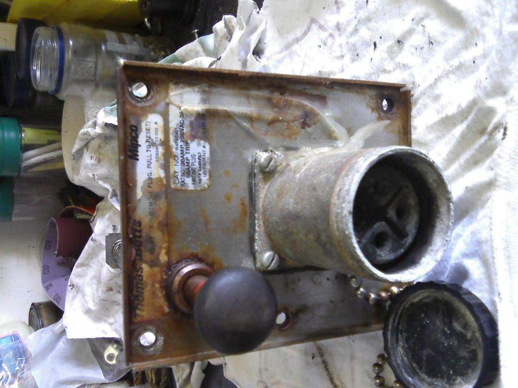
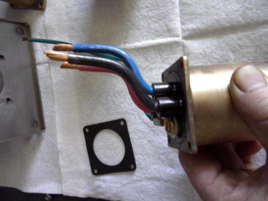
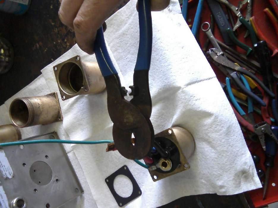
4 I cannot recall the particulars of this case as it occurred over 1 year ago already. Definitely salt water entering gang box either through bad or missing gasket or a warped frame. Break it down The circuit breaker lugs were all frozen

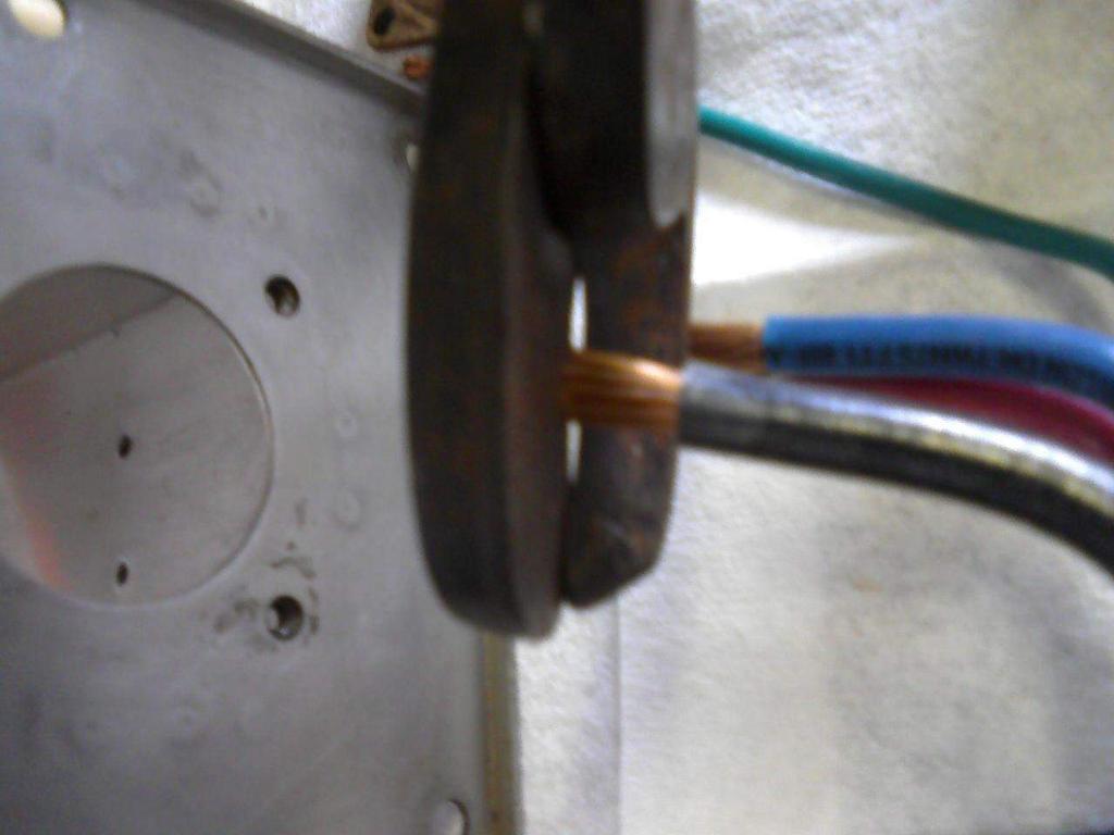
5 So the wires had to be cut


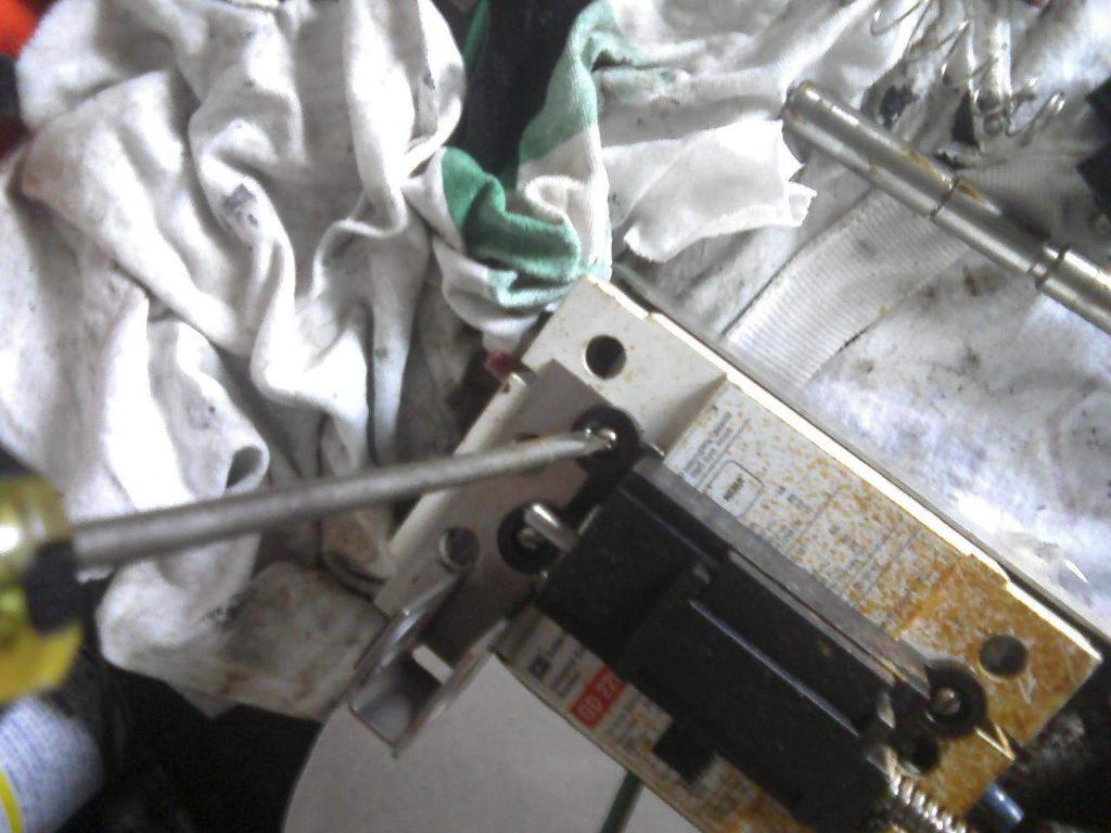
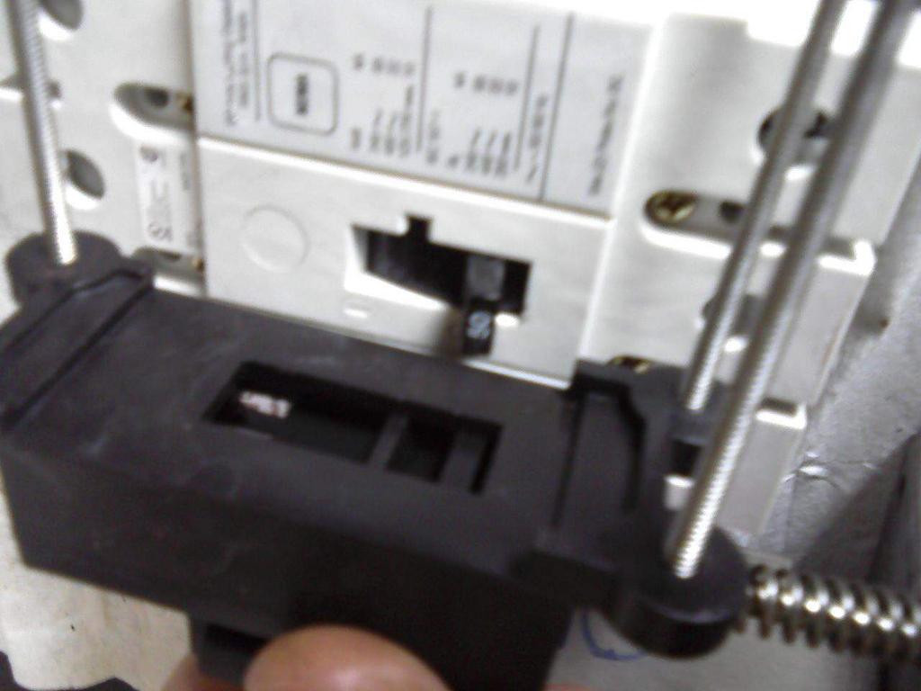
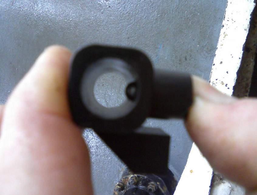
6 Remove retaining ring from its groove with a flat screwdriver

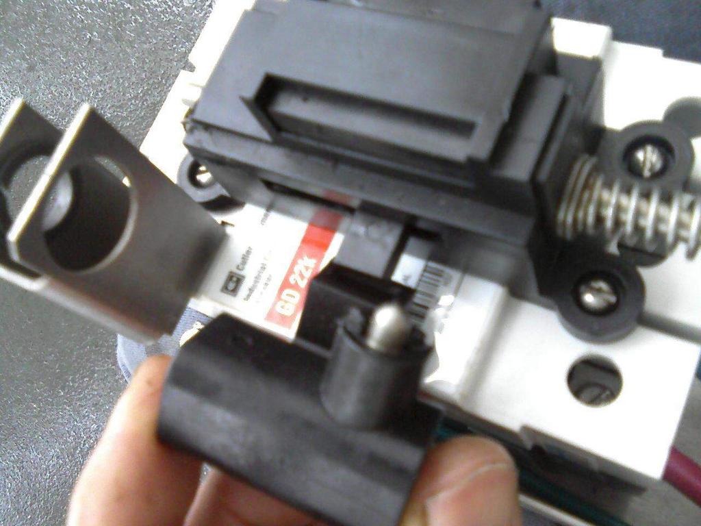
7 Spring compression retaining ring for interlock release

8 Pull down on on/off plunger to remove spring, interlock mechanism and plunger
9

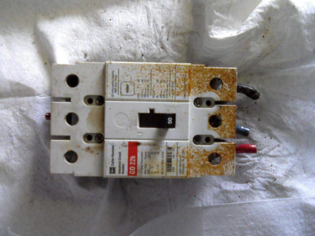
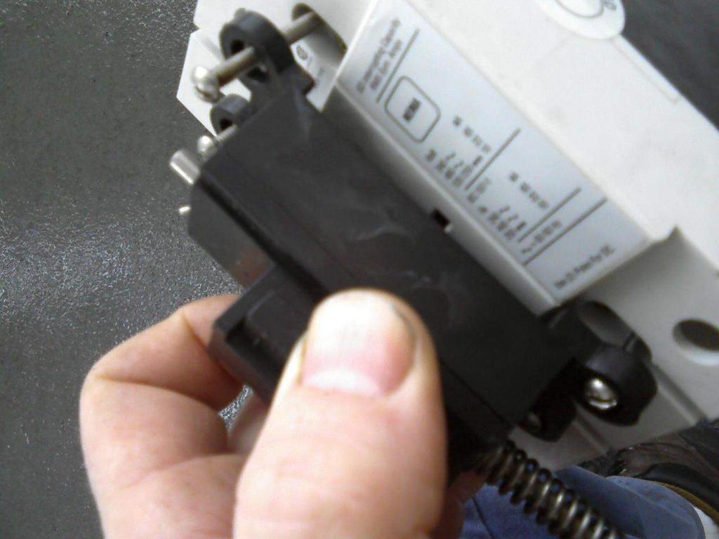
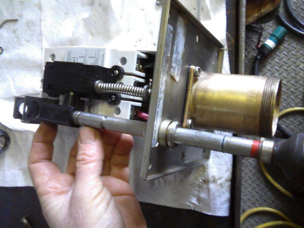
10 Remove the 4 screws securing breaker handle actuator unit, top plate and breaker to frame. Lift off breaker with actuator unit and ground pin.

11 Observe alignment with circuit breaker handle as it is removed. Be careful not to disturb cam positioning inside actuator. The plastic housing can separate.
12
13

14

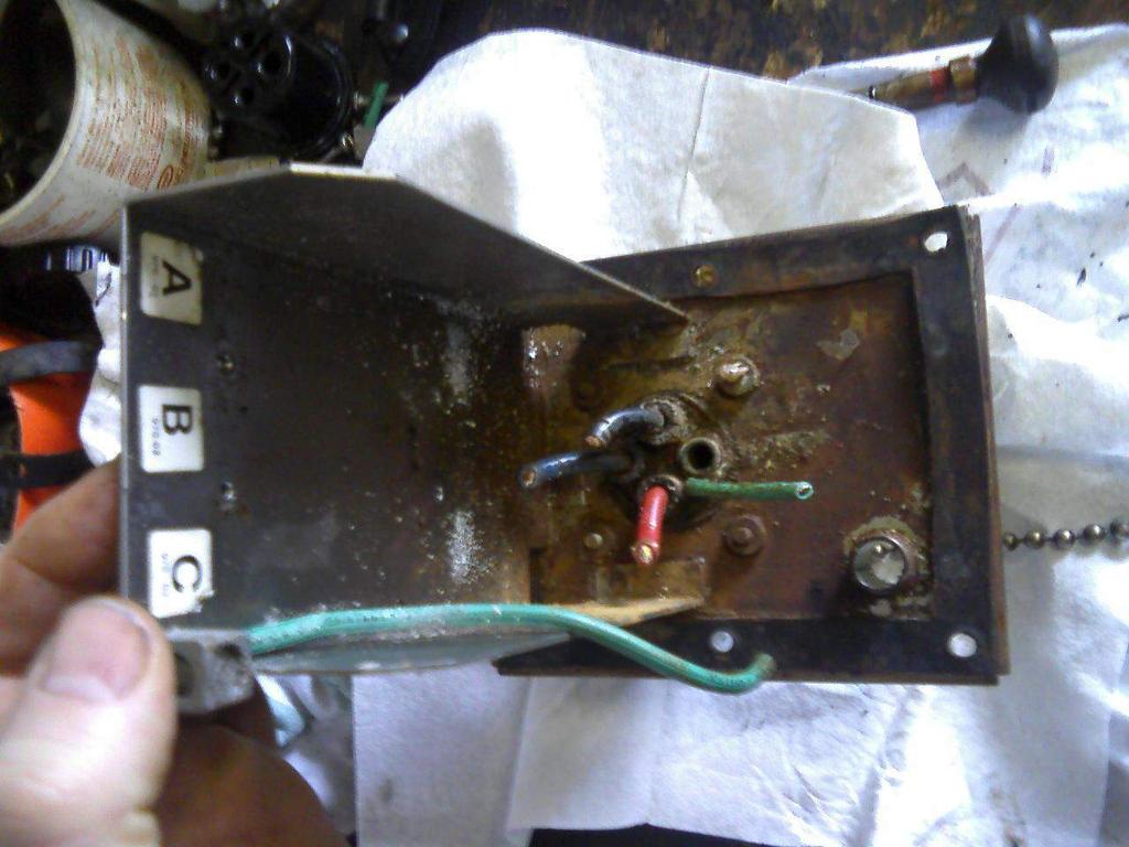
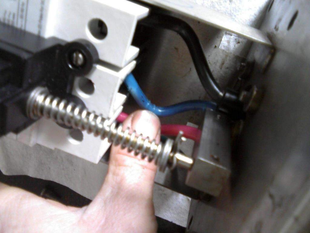
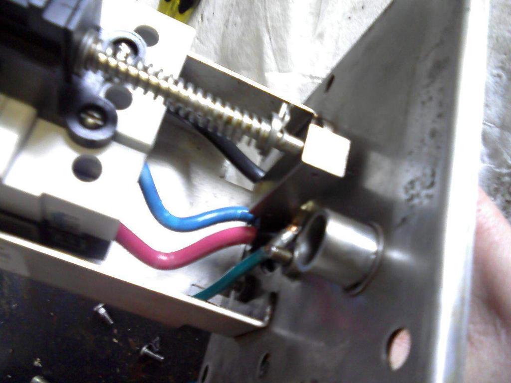
15 Remove brass receptacle housing
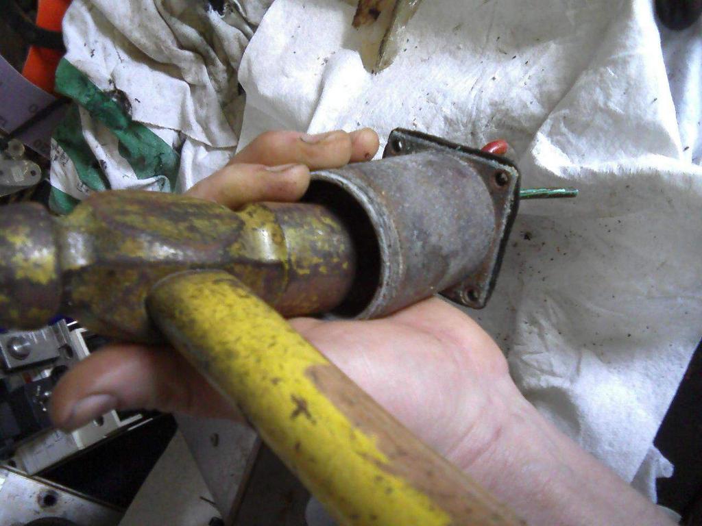
16

17 And remove receptacle from brass housing
18 Stainless steel and brass clean up nicely. The brass is a little more work but is necessary for the new receptacle to slide into the bore. Wire brush and medium grain crocus cloth work well. Some brass housings have a groove at base end for a retaining ring which needs to be scraped and brushed clean. Once brass housings are polished clean a thick coating of LPS 3 left to dry overnight will keep the creeping corrosion at bay.
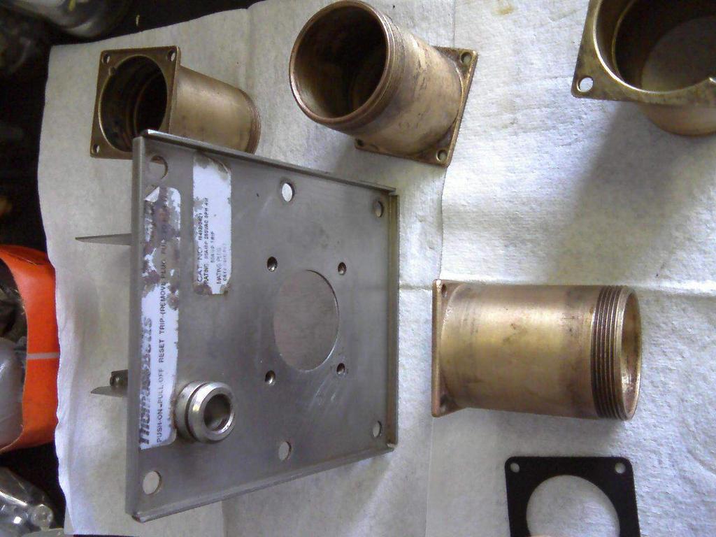
19
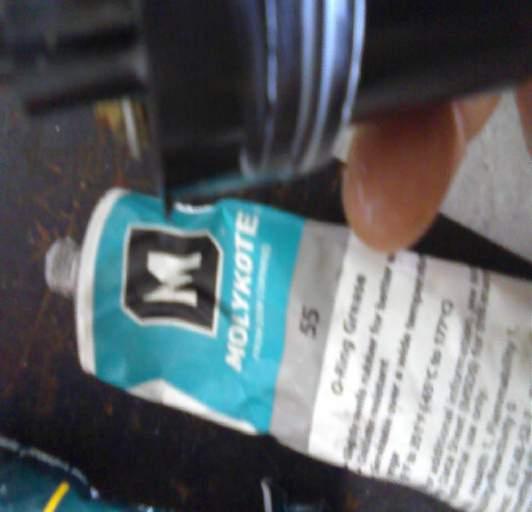
20 Reassemble The top 1/3 at flange end of the brass housing internal bore needs to be super clean for an easy fitting of new receptacle so only apply a light coat of LPS 3 if any here. Below the receptacle resting ledge a thick layer will be good. Dow Corning 111 valve lubricant and sealant works well on internal bore as well as Molykote 55 o-ring grease around receptacle o-ring. This will extend the life of your module and reduce your maintenance load.
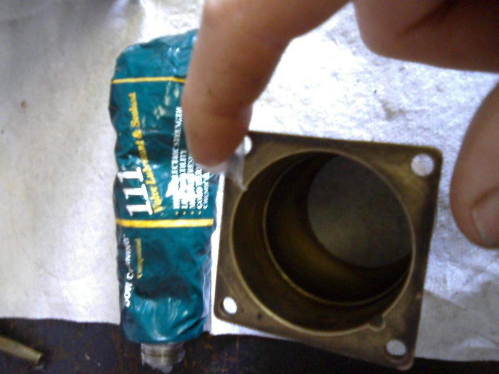
21
22

23 To prepare the receptacle wires for a quick and smooth installation into the circuit breaker lugs they must be shaped for a compressible helical spiral. The wires are thick stranded gauge so a 3/8 closed end wrench can be slipped over for bending leverage.

24 Do not try to cut the wires to length because the circuit breaker lugs are not in direct alignment with receptacle.
25 Install receptacle into brass housing aligning tab at base of receptacle with notch in brass housing flange. This prevents rotation of receptacle within housing. After shaping the wires, the ends will need to be trimmed flat or the contact surface between wire and lug will be reduced. Poor contact area will result in overheating and reduced life of circuit breaker and receptacle.
26
27
28

29

30 Reassemble circuit breaker actuator to circuit breaker.
31 With circuit breaker switch in off position align circuit breaker switch handle with actuator mechanism. Install circuit breaker and secure to frame with the 4 screws. Lightly lubricate receptacle mating gasket with 111 and place over housing flange. While guiding actuator ground plunger into bore of receptacle ground pin insert wires into circuit breaker lugs being careful not to bend any wire strands. Tighten lugs. Bend the B phase wire to the side to allow free movement of ground pin plunger. Tighten the 4 receptacle housing screws evenly until gasket touches frame plus ¼ turn or so being careful not to squeeze out the gasket.
32
33

34

35
36
37

38 With circuit breaker and receptacle secured, bench test for smooth operation.

39
40

41 To reassemble on/off plunger first place interlock release mechanism in position on its actuator.
42 The sliding cam actuated block mounted on circuit breaker is aligned with plunger in interlock release mechanism. With o-ring and shaft greased, insert on/off plunger through faceplate and interlock release. The cam actuated release plunger will interact with deep groove in on/off plunger shaft.
43

44 Place spring into position into guides above interlock release

45 Push on/off plunger up through interlock release, spring and guides until groove for retaining ring is visible above interlock release mechanism.

46 And insert ring between release mechanism and spring
47 The module is now complete and is ready for testing in same manner as shown in 480V version with ohm and meggar meter test equipment before installation for use.
POWER STEERING PUMP REBUILDING SPK101 Read instructions completely before removal & disassembly
 POWER STEERING PUMP REBUILDING SPK101 Read instructions completely before removal & disassembly DISASSEMBLY: 1. Remove pump from car and allow to drain. 2. Remove pulley from front of pump. This requires
METERING VALVE 2" STEM GUIDED
 2" STEM GUIDED All Rights Reserved. All contents of this publication including illustrations are believed to be reliable. And while efforts have been made to ensure their accuracy, they are not to be construed
INSTALLATION INSTRUCTIONS REPAIR SEAL KIT PowerSurvivor 40E
 INSTALLATION INSTRUCTIONS REPAIR SEAL KIT PowerSurvivor 40E PURPOSE OF THE KIT The Repair Seal Kit should be installed after 1000 hours of operation. It should be installed regardless of whether or not
TECHNICAL BULLETIN. Servicing Meritor TM EASY STEER PLUS TM Series Unitized Truck Hub Unit Assembly
 TP-9819 Revised 12-97 TECHNICAL BULLETIN Servicing Meritor TM EASY STEER PLUS TM Series Unitized Truck Hub Unit Assembly Attention Freightliner dealers and direct warranty customers. Please discard this
354 CHAPTER EIGHT WATER PUMP
 354 CHAPTER EIGHT 33 Shift handle F : Forward N : Neutral R : Reverse proper alignment of the water tube to the water pump opening during each installation attempt. Make sure the locating pins enter the
HIGH PERFORMANCE TRANSMISSION PARTS Instructions. Line Pressure Booster Kit. TCC Control Plunger Valve Kit. Line Pressure Modulator Plunger Valve Kit
 Performance Pack Ford 4R100 Part No. HP-4R100-01 Line Pressure Booster Kit Line-to-Lube Pressure Regulator Valve Line Pressure Booster Kit Valve Sleeve O-Rings (2) TCC Control Plunger Valve Kit Front Lube/Drainback
Transmission Overhaul Procedures-Bench Service
 How to Assemble the Lower Reverse Idler Gear Assembly Special Instructions In 1996 Eaton changed the reverse idler system design. In the nut design, the reverse idler bearing was lubricated through a hole
LOW PRESSURE BALANCED VALVE DIAPHRAGM BALANCED
 DIAPHRAGM BALANCED All Rights Reserved. All contents of this publication including illustrations are believed to be reliable. And while efforts have been made to ensure their accuracy, they are not to
HIGH PERFORMANCE TRANSMISSION PARTS Instructions. Line Pressure Booster Kit. TCC Control Plunger Valve Kit. Line Pressure Modulator Plunger Valve Kit
 Performance Pack Ford 4R100 Part No. HP-4R100-01 Line Pressure Booster Kit Line-to-Lube Pressure Regulator Valve Line Pressure Booster Kit Valve Sleeve O-Rings (2) TCC Control Plunger Valve Kit Front Lube/Drainback
HIGH PRESSURE CONTROL VALVE R2L ACTUATOR
 R2L ACTUATOR All Rights Reserved. All contents of this publication including illustrations are believed to be reliable. And while efforts have been made to ensure their accuracy, they are not to be construed
2008 Toyota Tundra 4WD Brake Job: A Quick Job and Even Quicker Write-Up.
 FRONT BRAKES: 2008 Toyota Tundra 4WD Brake Job: A Quick Job and Even Quicker Write-Up. 1. Remove this bolt holding brake line bracket to the suspension. 2. I had to replace all 4 rotors at 60K miles, so
Service Manual Air Plus Second Stage
 Service Manual Air Plus Second Stage Includes XS Series Second Stage Copyright 2002, Cressi-sub Revised 3/2002 2 Air Plus Second Stage Service Manual Contents BEFORE STARTING... 3 DISASSEMBLY... 3 PARTS
Off-Highway Axle Planetary Wheel Ends
 Maintenance Manual MM-1189 Off-Highway Axle Planetary Wheel Ends Revised 06-16 Service Notes About This Manual This manual provides service and repair procedures for planetary wheel ends on off-highway
70001 and Clutch Rebuild Instructions
 70001 and 70010 Clutch Rebuild Instructions Brinn, Incorporated 1615 Tech Drive Bay City, MI 48706 Telephone 989.686.8920 Fax 989.686.6520 www.brinninc.com Notice Use these instructions if you only want
CARBURETION. Tank Mount, Horizontal Crankshaft. Vacu-Jet - All
 Page 1 of 1 Vacu-Jet - All Carburetor Adjustment Initial 1. Turn adjustment needle clockwise until it makes light contact with the seat. Do not force. 2. The initial setting of adjustment needle is made
BETTIS SERVICE INSTRUCTIONS DISASSEMBLY AND REASSEMBLY FOR CB-SR-S SEISMIC SPRING RETURN SERIES PNEUMATIC ACTUATORS
 BETTIS SERVICE INSTRUCTIONS DISASSEMBLY AND REASSEMBLY FOR CB-SR-S SEISMIC SPRING RETURN SERIES PNEUMATIC ACTUATORS PART NUMBER: 102264 REVISION: "C" DATE: November 2000 Page 1 of 11 1.0 INTRODUCTION 1.1
SERVICE PARTS LIST 1-1/8" ROTARY HAMMER MILWAUKEE ELECTRIC TOOL CORPORATION W. LISBON RD., BROOKFIELD, WI Drwg.
 00 0 200 204 276 EXAMPLE: Component Parts (Small #) Are Included When Ordering The Assembly (Large #). SERVICE PARTS LIST SPECIFY CATALOG NO. AND SERIAL NO. WHEN ORDERING PARTS PAGE 1 OF 3 BULLETIN NO.
Ultra Elite Facepiece: AirHawk II Air Mask
 Ultra Elite Facepiece: AirHawk II Air Mask MAINTENANCE AND REPAIR MSA 713 (L) Rev. 1 MSA 2017 Prnt. Spec. 10000005389(I) Mat. 10104249 Doc. 10104249 PARTS LIST Ultra Elite Facepiece (Complete) Item P/N
980 B Wheel Loader S/n 89P1 & Up Volume 1 of 2
 Caterpillar Service Manual 980 B Wheel Loader S/n 89P1 & Up Volume 1 of 2 Service Manual THIS IS A MANUAL PRODUCED BY JENSALES INC. WITHOUT THE AUTHORIZATION OF CATERPILLAR OR IT S SUCCESSORS. CATERPILLAR
SUZUKI SQ 416/420/625 M.Y TRANSMISSION SERVICE MANUAL - MANUAL - AUTOMATIC - TRANSFER - DIFFERENTIALS
 SUZUKI SQ 416/420/625 M.Y 1998-2005 TRANSMISSION SERVICE MANUAL - MANUAL - AUTOMATIC - TRANSFER - DIFFERENTIALS WARNING/CAUTION/NOTE IMPORTANT Please read this manual and follow its instructions carefully.
kit contents trail-safe samurai inner axle seal suzuki samurai (all engines) InstalLation Instructions
 InstalLation Instructions") InstalLation Instructions trail-safe samurai inner axle seal 300748-3-kit 1986-1995 suzuki samurai (all engines) kit contents 5356 PINE AVE FRESNO, CA 93727 USA TOLL FREE: 877.4X4.TOYS WORLDWIDE: 559.252.4950
InstalLation Instructions trail-safe samurai inner axle seal 300748-3-kit 1986-1995 suzuki samurai (all engines) kit contents 5356 PINE AVE FRESNO, CA 93727 USA TOLL FREE: 877.4X4.TOYS WORLDWIDE: 559.252.4950
INSTRUCTION MANUAL INSTALLING NEW GREASE IN UT SERIES PNEUMATIC ACTUATOR
 INSTRUCTION MANUAL INSTALLING NEW GREASE IN UT SERIES PNEUMATIC ACTUATOR This instruction manual explains the steps required to degrease and install new grease into the Max-Air UT series pneumatic actuator.
CARBURETOR - HITACHI 2-BBL
 CARBURETOR - HITACHI 2-BBL 1986 Isuzu Trooper II 1986 Hitachi Carburetors HITACHI DCH340, DCR384, DFP340, DFP384 & DHP340 2-BARREL P UP & Trooper II DESCRIPTION Carburetor is a 2-barrel downdraft type
DISASSEMBLY AND ASSEMBLY (Continued)
") 205-03-23 Front Drive Axle/Differential Ford 8.8-Inch Ring Gear 205-03-23 49. Measure the ring gear backlash at four places to obtain a consistent reading. 1 Mount the special tools on the indicator base.
205-03-23 Front Drive Axle/Differential Ford 8.8-Inch Ring Gear 205-03-23 49. Measure the ring gear backlash at four places to obtain a consistent reading. 1 Mount the special tools on the indicator base.
OPERATION AND MAINTENANCE INSTRUCTIONS
 OPERATION AND MAINTENANCE INSTRUCTIONS 334 SERIES THREE-PIECE BALL VALVES 1/4 to 2-1/2 Installation and Operation Always install your valve according to accepted industry standards and practices and operate
Technical Data TYPE A SERIES AIR ADJUSTED PILOT SPENCE ENGINEERING COMPANY, INC. 150 COLDENHAM ROAD, WALDEN, NY SD 4011 OPERATING PRINCIPLE
 Technical Data SD 4011 SPENCE ENGINEERING COMPANY, INC. 150 COLDENHAM ROAD, WALDEN, NY 12586-2035 TYPE A SERIES AIR ADJUSTED PILOT PRINTED IN U.S.A. SD 4011/9504 Type A or A83 (wt 6 lb) Type A53 or A 85
ASSEMBLY, INSTALLATION, AND REMOVAL OF CONTACTS AND MODULES
 ASSEMBLY, INSTALLATION, AND REMOVAL OF CONTACTS AND MODULES FOR MICRO POWER CONTACTS AND MODULES Table of Contents SECTION 1 RECEIVER CONTACT ASSEMBLY INSTRUCTIONS SECTION 2 ITA CONTACT ASSEMBLY INSTRUCTIONS
INSTALLATION INSTRUCTIONS REPAIR SEAL KIT PowerSurvivor 160E
 INSTALLATION INSTRUCTIONS REPAIR SEAL KIT PowerSurvivor 160E PURPOSE OF THE KIT The Repair Seal Kit should be installed after 500 hours of operation. It should be installed regardless of whether or not
INSTRUCTIONS FOR CONTINUED AIRWORTHINESS
 INSTRUCTIONS FOR CONTINUED AIRWORTHINESS for GROVE MODEL 40-108 & 40-208 MAIN WHEELS DOCUMENT 12012-12 REV IR January 16, 2012 TABLE OF CONTENTS SECTION PAGE Title Page...1 Table of Contents...2 Record
Installation Instructions for. For Use When Converting Model (V)M42(B) Vented Decorative Fireplace. Fold Bi-Fold Door After Releasing
M42(B) Vented Decorative Fireplace. Fold Bi-Fold Door After Releasing") Installation Instructions for PCBM-42 conversion kit Converting from Natural Gas to Propane/LP Gas For Use When Converting Model (V)M42(B) Vented Decorative Fireplace This conversion kit must be installed
Installation Instructions for PCBM-42 conversion kit Converting from Natural Gas to Propane/LP Gas For Use When Converting Model (V)M42(B) Vented Decorative Fireplace This conversion kit must be installed
PILLOWS DECK-MOUNT BATH FAUCET WITH FLUME SPOUT
 PILLOWS DECK-MOUNT BATH FAUCET WITH FLUME SPOUT BEFORE YOU BEGIN NOTES Observe all local plumbing and building codes. Advance planning before installation is crucial. Carefully read the entire instructions
Waukesha Cherry-Burrell Valves
 BUTTERFLY VALVES 1 Waukesha Cherry-Burrell Valves BUTTERFLY VALVES 200 Valves Series Butterfly Valves 250 Series Ball Valves Manual & Automatic Actuators Read and understand this manual prior to operating
ANDCO Eagle Actuator Instruction Manual
 ANDCO Actuators ANDCO Eagle Actuator Instruction Manual The information contained in this manual is essential to safe, successful, long term operation of your Andco Eagle Linear Actuator. Read and follow
Troubleshooting. Pull Type Clutches - Poor Release
 Troubleshooting Pull Type Clutches - Poor Release Complaint Possible Causes Corrective Action Poor Release Intermediate plate sticking on drive lugs due to cocked drive pins (AS and EP 1402 only) (see
26/01/2017 3GR-FSE ENGINE MECHANICAL: ENGINE UNIT: DISASSEMBLY; 2006 MY GS300 [01/ ]
![26/01/2017 3GR-FSE ENGINE MECHANICAL: ENGINE UNIT: DISASSEMBLY; 2006 MY GS300 [01/ ]](/thumbs/85/92233007.jpg "26/01/2017 3GR-FSE ENGINE MECHANICAL: ENGINE UNIT: DISASSEMBLY; 2006 MY GS300 [01/ ]") Last Modified: 8-24-2016 6.6 A Doc ID: RM000000T4X000X Model Year Start: 2006 Model: GS300 Prod Date Range: [01/2005 - ] Title: 3GR-FSE ENGINE MECHANICAL: ENGINE UNIT: DISASSEMBLY; 2006 MY GS300 [01/2005
Last Modified: 8-24-2016 6.6 A Doc ID: RM000000T4X000X Model Year Start: 2006 Model: GS300 Prod Date Range: [01/2005 - ] Title: 3GR-FSE ENGINE MECHANICAL: ENGINE UNIT: DISASSEMBLY; 2006 MY GS300 [01/2005
Service Manual Air Tech Second Stage
 Service Manual Air Tech Second Stage Copyright 2002, Cressi-sub Revised 3/2002 2 Air Tech Second Stage Service Manual Contents BEFORE STARTING... 3 DISASSEMBLY... 3 PARTS CLEANING AND LUBRICATION... 9
NOTE: Visit our website at for video repair procedures, under the Tools section.
 Repair Instructions Hypro Repair Tools: Tool Box No. 3010-0168 1/4" Allen Wrench No. 3020-0008 Support Bars (2) No. 3010-0064 Port Brush No. 3010-0066 1/16" Allen Wrench No. 3020-0009 Brush Holder No.
Tillotson Tc3A Carburator
 Tillotson Tc3A Carburator 176 FUEL SYSTEMS - 5B-11 CENTER BOWL TYPE CARBURETOR Removal 1. Remove front cowl cover and wrap-around cowl. 2. Remove swivel link from lower carburetor. (Figure 2) 3. Loosen
Engine. Special Tool(s) Compressor, Piston Ring 303-D032 (D81L-6002-C) or equivalent. Compressor, Valve Spring (T93P-6565-AR)
 Compressor, Piston Ring 303-D032 (D81L-6002-C) or equivalent. Compressor, Valve Spring (T93P-6565-AR)") SECTION 303-01C: Engine 5.4L (4V) 2009 Mustang Workshop Manual ASSEMBLY Procedure revision date: 12/12/2008 Engine Special Tool(s) Compressor, Piston Ring 303-D032 (D81L-6002-C) or equivalent Compressor,
SECTION 303-01C: Engine 5.4L (4V) 2009 Mustang Workshop Manual ASSEMBLY Procedure revision date: 12/12/2008 Engine Special Tool(s) Compressor, Piston Ring 303-D032 (D81L-6002-C) or equivalent Compressor,
Table of Contents Visual Inspection and Neutralizing... 3 Disassembly
 1 Table of Contents Visual Inspection and Neutralizing... 3 Disassembly... 3... 4... 4 Cleaning... 4 Inspection... 4 Reconditioning of Valve Seats... 5 Lapping Procedures... 5 Lapping Blocks... 5 Lapping
MANUAL TRANSMISSIONS Mitsubishi F4M20, F5M20, F5M30 & KM200 Series TRANSMISSION APPLICATION
 Article Text ARTICLE BEGINNING MANUAL TRANSMISSIONS Mitsubishi F4M20, F5M20, F5M30 & KM200 Series APPLICATION TRANSMISSION APPLICATION Vehicle Application Transmission Model Chrysler Motors (2WD) 4-Speed
Installation Instructions
 Installation Instructions Rear Disc Brake Conversion Kit Item # RC4001, RC4001X Applications: Mopar 7.25, 8.25, 9.25 Axles Thank you for choosing Leed Brakes for your automotive product needs. Before you
This LED flashtube kit covers models 400, 404, 500, 504, 600, 680 & 506.
 L.E.D. INSTRUCTIONS I D T S O T U B I R M O C R Y N A P Kit contains: This LED flashtube kit covers models 400, 404, 500, 504, 600, 680 & 506. For the power supply: 1-LED power supply circuit board, 2
Anderson Greenwood Series 800 POSRV Installation and Maintenance Instructions
 Before installation these instructions must be fully read and understood Table of contents 1. General valve description and start-up... 1 2. Main valve maintenance... 2 3. Pilot maintenance... 6 4. Pilot
Service Bulletin No. 358
 Service Bulletin No. 358 MODEL TYPE SECTION/GROUP DATE J4500 Series Coaches Field Change Program 15--Wheel April 13, 2011 SUBJECT ARVINMERITOR TAG AXLE TORQUE PLATE TO SPINDLE FLANGE FASTENERS CONDITIONS
Maintenance instruction
 Maintenance instruction This maintenance instruction is a step-by-step instruction for service and maintenance on Stafsjö s HG valve. Same procedure also applies for HL, HP and HPT. The instruction shall
Application Note Original Instructions. Gas Fuel Control Valve (GFCV) O-ring Field Replacement Procedure
 O-ring Field Replacement Procedure") Application Note 51299 Original Instructions Gas Fuel Control Valve (GFCV) O-ring Field Replacement Procedure DEFINITIONS This is the safety alert symbol. It is used to alert you to potential personal
Application Note 51299 Original Instructions Gas Fuel Control Valve (GFCV) O-ring Field Replacement Procedure DEFINITIONS This is the safety alert symbol. It is used to alert you to potential personal
2007 Hummer H Driveline/Axle Propeller Shaft - H3. Fastener Tightening Specifications Specification Application
 2007 Driveline/Axle Propeller Shaft - H3 SPECIFICATIONS FASTENER TIGHTENING SPECIFICATIONS Fastener Tightening Specifications Specification Application Metric English Bolt - Front Propeller Shaft CV Joint
Steering Column. Disassembly. 1. Remove instrument panel cover and reinforcement from vehicle as described in this section.
 Page 1 of 14 Section 11-04A: Steering Column, Ranger 1997 Aerostar/Ranger Workshop Manual DISASSEMBLY AND ASSEMBLY Procedure revision date: 05/17/2000 Steering Column Disassembly 1. Remove instrument panel
SD Bendix E-10PR Retarder Control Brake Valve DESCRIPTION. OPERATION - Refer to Figure 2
 SD-03-832 Bendix E-10PR Retarder Control Brake Valve MOUNTING PLATE SUPPLY 4 PORTS ELECTRICAL AUXILIARY DESCRIPTION TREADLE RETARDER CONTROL SECTION EXHAUST DELIVERY 4 PORTS FIGURE 1 - E-10PR RETARDER
Oreck Magnesium Series Service Manual. The Oreck Manufacturing Company
 Oreck Magnesium Series Service Manual The Oreck Manufacturing Company 08/2012 10/2011 The Oreck Manufacturing Company Contents Covering all Magnesium Upright Models Including: LW100, LW125, LW1000, AND
This file is available for free download at
 This file is available for free download at http://www.iluvmyrx7.com This file is fully text-searchable select Edit and Find and type in what you re looking for. This file is intended more for online viewing
TECHNICAL BULLETIN. TP Issued Servicing Rockwell s TB Series Trailer Axles with Unitized Hub Assemblies
 TECHNICAL BULLETIN TP-96175 Issued 12-96 Servicing Rockwell s TB Series Trailer Axles with Unitized Hub Assemblies TB Series Trailer Axles Introduction Rockwell s TB series trailer axle features a permanently
TIMING CHAIN. TIMING CHAIN Removal and Installation EM-35 PFP:13028 EBS00I2X KBIA2511E
 TIMING CHAIN Removal and Installation PFP:13028 EBS00I2X A EM C D E F G H I J K L M KBIA2511E EM-35 1. Camshaft sprocket (left bank EXH) 2. Camshaft sprocket (left bank INT) 3. Camshaft sprocket (right
NAVAL INSTALLATION INSTRUCTIONS PISTON TYPE FLUSHOMETER FOR EXPOSED CLOSET AND URINAL INSTALLATIONS LIMITED WARRANTY
 NAVAL NAVAL I.I. Code No. 0816176 Rev. 1 INSTALLATION INSTRUCTIONS PISTON TYPE FLUSHOMETER FOR EXPOSED CLOSET AND URINAL INSTALLATIONS Certified Made in the U.S.A Exposed Closet Flushometer 1-1/2" Top
REMOVAL & INSTALLATION
 REMOVAL & INSTALLATION CENTER BEARING SUPPORT ASSEMBLY Removal 1. With transmission in neutral and parking brake off, raise vehicle. Scribe alignment marks on all flange/yokes and slip joints to be disassembled
TABLE OF CONTENTS. Ram Assembly
 TABLE OF CONTENTS DUC Cover------------------------------------------------------------------------------------ 00 Table of Contents----------------------------------------------------------------------------
2-12 Grooved End Dual Disc Check Valve. Operation, Maintenance and Installation Manual
 Manual No. DDCV-OM4-1 2-12 Grooved End Dual Disc Check Valve Operation, Maintenance and Installation Manual INTRODUCTION... 1 RECEIVING AND STORAGE... 1 DESCRIPTION OF OPERATION... 1 INSTALLATION... 2
Model 4360 Teardown and Reassembly Instructions
 Clean the outside surface of the transaxle. Place the shifter in neutral position. Remove detent cover screw (item 3), detent cover (item 4), detent springs (item 5), and detent balls (item 6). Use a magnet
Ford Racing Hot Rod Performance Camshafts (05-10 GT)
") Time Necessary: 8 hours Tools Required: Ford Racing Hot Rod Performance Camshafts (05-10 GT) 10mm deep socket 11mm socket 8 mm deep socket 15 mm deep socket 18 mm deep socket Universal Joint socket (articulated
Time Necessary: 8 hours Tools Required: Ford Racing Hot Rod Performance Camshafts (05-10 GT) 10mm deep socket 11mm socket 8 mm deep socket 15 mm deep socket 18 mm deep socket Universal Joint socket (articulated
Cryogenic Wafer-Sphere Butterfly Valves
 Cryogenic Wafer-Sphere Butterfly Valves 3"-12" Installation, Maintenance and Operating Instructions IMO-16 4/2015 2 IMO-13 Table of Contents DESCRIPTION..................................... 3 Eccentric
DRIVE AXLE Nissan 240SX DESCRIPTION & OPERATION AXLE RATIO & IDENTIFICATION AXLE SHAFT & BEARING R & I DRIVE SHAFT R & I
 DRIVE AXLE 1990 Nissan 240SX 1990 DRIVE AXLES Rear Axle - R200 240SX, 300ZX DESCRIPTION & OPERATION The axle assembly is a hypoid type gear with integral carrier housing. The pinion bearing preload adjustment
Installation Instructions Street Bandit Shifter
 Installation Instructions Street Bandit Shifter Part Number 80797 (see www.bmracing.com for the latest technical product information) 2006, 2000 by B&M Racing and Performance Products The B&M Street Bandit
1994 Mitsubishi Eclipse GS
 APPLICATIONS CHRYSLER MOTORS MANUAL TRANS OVERHAUL - MITSUBISHI W5M & W6M SERIES MANUAL TRANSMISSIONS Mitsubishi W5M31, TRANSMISSION APPLICATIONS (CHRYSLER MOTORS) Vehicle Application Transmission Model
DESCRIPTION & OPERATION
 2004 BRAKES Disc - TSX DESCRIPTION & OPERATION WARNING: DO NOT use air pressure or a dry brush to clean brake assemblies. Avoid breathing brake dust. Use OSHA-approved vacuum cleaner for cleaning and collecting
G5 Stainless Steel Brakes Owners Manual
 G5 Stainless Steel Brakes Owners Manual Important: Read all of this Stainless Steel Disc Brake Manual before starting installation or removal of any part on the disc brakes. TIE DOWN ENGINEERING 255 Villanova
All-American Hose 4 and 5 Storz Coupling Service Manual
 All-American Hose 4 and 5 Storz Coupling Service Manual 1. Storz Coupling Components a. Storz Head The Storz head is the swivel connection on the Storz coupling. Its primary features are the lugs and ramps
Electric motor testing
 Electric motor testing MOTOR (MODELS EJ4-4001 AND EJ8-4001A) 23 GENERAL INFORMATION The vehicle is equipped with a 48-volt DC, shunt-wound, reversible traction motor. The shunt-wound motor is designed
B Series 1/2" to 2" 2-Way and 3-Way Bronze Control Valves
 INSTALLATION AND MAINTENANCE INSTRUCTIONS IM-1-620-US November 2015 B Series 1/2" to 2" 2-Way and 3-Way Bronze Control Valves 1. Safety 2. Technical details 3. Installation and Commissioning 4. Maintenance
CARTER DOWNDRAFT CARBURETOR Terraplane All Models. Technical Information
 CARTER DOWNDRAFT CARBURETOR 1934 Terraplane All Models Technical Information . Carter W-1 Downdraft Carburetors 1934 Terraplane Challenger, Model KS NOTE: Terraplane Models. Carburetor fitted with Anti-
~ :H:OlVD.A. CB1000C CLUTCH Date of Issue: Sept., 1982 HONDA MOTOR CO., LTD.
 ~ :H:OlVD.A. CB1000C 8-0 118 ~ :H:OlVD.A. CB1000C 8. SERVICE INFORMATION TROUBLESHOOTING COVER REMOVAL REMOVAL 8-1 8-2 8-3 8-3 INSTAllATION COVER INSTAllATION STARTER DISASSEMBLY STARTER ASSEMBLY 8-6 8-9
Evo X Walbro 450 Pump System
 Evo X Walbro 450 Pump System Installation Guide Please contact us at sales@wtftuned.com with any additional questions Tools required: 8 mm socket and wrench, needle-nose pliers, razor, drill w/ 5/64 bit,
GrilleGuy.com, LLC. Installation Instructions and Care Guide : Toyota Tacoma Grille UPPER GRILLE
 Installation Instructions and Care Guide : 2001 2004 Toyota Tacoma Grille Thanks again for purchasing your custom grille insert from GrilleGuy.com. The following are some general guidelines that will simplify
Valtek Auxiliary Handwheels and Limit Stops
 Valtek Auxiliary s and Limit Stops Table of Contents Page 1 General information 2 Installation 2 Side-mounted handwheels, size 25 and 50 (linear actuators) 3 Side-mounted handwheels, size 100 and 200 (linear
3" & 4" Cast Iron Self-Priming Centrifugal Pump Instruction Manual
 12 3" & 4" Cast Iron Self-Priming Centrifugal Pump Instruction Manual 333 & 444 Series Read these instructions and the instructions covering operation of the pump drive unit. Do not operate the gas engine
5-3. ENGINE BOTTOM END
 BOTTOM END ENGINE DRIVE SHAFT 5-3-1 CRANKCASE Remover: 560012 Installer: 560011 Remover: 560014 Installer: 560013 CRANKSHAFT 5-3-2 WATER PUMP, OIL PUMP Installer: 560025 Remover: 560024 Installer: 560003
CS Fiber Optic Splice Case. Instruction
 3 2179-CS Fiber Optic Splice Case Instruction 2179-CS Fiber Optic Splice Case Description 1.0 General 1.1 The 3M 2179-CS Fiber Optic Splice Cases are closures that can be used in buried, underground, aerial,
HOW TO INSTALL FORD RACING HOT ROD PERFORMANCE CAMSHAFTS MUSTANG GT
 HOW TO INSTALL FORD RACING HOT ROD PERFORMANCE CAMSHAFTS 2005-2010 MUSTANG GT INSTALLATION TIME: 8 HOURS Introduction: This instruction set is intended to be a step by step guide for installing Ford Racing
Installation Instructions
 Installation Instructions Rear Disc Brake Conversion Kit Item # RC2001, RC2001X Applications: Mopar 8-3/4 & 9-3/4 Rear Axles Thank you for choosing Leed Brakes for your automotive product needs. Before
INSTALLATION INSTRUCTIONS REPAIR SEAL KIT Survivor 35
 INSTALLATION INSTRUCTIONS REPAIR SEAL KIT Survivor 35 PURPOSES OF THE KIT Over time, the dynamic seals and O-rings in the PowerSurvivor-35 and Survivor-35 will wear. The Repair Seal Kit contains the major
CP-1, CP-2, CP-2L & CPD-2 Series Overhaul
 Replacement of Mechanical Seals for CM, CMU, CS and CSU Series Pumps Installation Instructions Form No. F-1031 Section 5013 Issue Date 03/01/85 Rev. Date 02/08/11 CP-1, CP-2, CP-2L & CPD-2 Series Overhaul
Front Bucket Seat Upholstery
 Specter Off-Road, Inc. 21600 Nordhoff St. Chatsworth, CA 91311 USA www.sor.com, (818)882-1238, Fax: (818) 882-7144 sor@sor.com Luxury Seat Upholstery Installation Instructions Front Bucket Seat Upholstery
POWER STEERING TO INDEX POWER STEERING SYSTEM PRECAUTIONS... OPERATION CHECK... PROBLEM SYMPTOMS TABLE... VANE PUMP ASSEMBLY COMPONENTS...
 TO INDEX STEERING POWER STEERING POWER STEERING SYSTEM PRECAUTIONS.............................................. OPERATION CHECK......................................... PROBLEM SYMPTOMS TABLE.................................
FE 35, 40, 55, EC Every time you open the housing, clean the motor with a soft brush.
 FE 35, 40, 55, EC 70 1 Service Manual FE 35, FE 40, FE 55 Electric Trimmers, EC 70 Electric Edger As the design concept of the FE 35 and FE 40 trimmers is almost identical, the descriptions and servicing
ENGINE MEASUREMENTS ENGINE MEASUREMENTS AND SPECIFICATIONS CYLINDER HEAD. Measure Cylinder Compression. Using Telescoping Gauges and Hole Gauges
 ENGINE MEASUREMENTS AND SPECIFICATIONS Tool List Qty. Required Compression Gauge, 20 kgf/cm²: E-Z-GO Part No. N/A... 1 Compression Gauge Adapter, M14 1.25: E-Z-GO Part No. N/A... 1 Valve Seat Cutter, 45-35
CONTROL VALVES. Installation, Maintenance & Operating Instructions. Read these instructions carefully before installation or servicing.
 KOSO HAMMEL DAHL CONTROL VALVES KOSO HAMMEL DAHL 253 Pleasant Street West Bridgewater, MA 02379 tel: 774.517.5300 fax: 774.517.5230 www.hammeldahl.com Installation, Maintenance & Operating Instructions
MANUAL TRANSAXLE Return to Main Table of Contents
 MANUAL TRANSAXLE Return to Main Table of Contents GENERAL... 2 MANUAL TRANSAXLE CONTROL... 12 SHIFT LEVER ASSEMBLY... 14 MANUAL TRANSAXLE... 15 MANUAL TRANSAXLE ASSEMBLY... 17 FIFTH SPEED SYNCHRONIZER
Maintenance Information
 80234313 Edition 1 June 2006 Air Grinder, Die Grinder, Sander and Belt Sander Series G1 (Angle) Maintenance Information Save These Instructions WARNING Always wear eye protection when operating or performing
1988 Jeep Truck Wrangler L L VIN H TBI Copyright 2013, ALLDATA 10.52SS Page 1 Technical Service Bulletin # Date:
 1988 Jeep Truck Wrangler L4-150 2.5L VIN H TBI Copyright 2013, ALLDATA 10.52SS Page 1 Technical Service Bulletin # 025288 Date: 880711 Right Front Axle Shaft Seal - Installation Models 1986-88 Jeep Comanche,
BIDET KEEP THIS INSTRUCTION BOOKLET FOR FUTURE REFERENCE
 BIDET KEEP THIS INSTRUCTION BOOKLET FOR FUTURE REFERENCE Vacuum Br eaker supply lines. Hole size for the spout and handle trim is 1-1/4 Vacuum Breaker Installation NOTE: See diagram on next page for removing
Maintenance Information
 45530136 Edition 1 July 2008 Electric Screwdrivers EL 24V DC Series Maintenance Information Save These Instructions WARNING Always wear eye protection when operating or performing maintenance on this tool.
Tidland Raptor Series Torque Chuck
 TIDLAND WINDING SOLUTIONS Tidland Raptor Series Torque Chuck User Manual EN MI 660289 1 H Includes 3", 4" 6" chucks and adapters TABLE OF CONTENTS Caution... 3 Tidland Customer Service... 3 Recommended
INSTALLATION INSTRUCTIONS
 INSTALLATION INSTRUCTIONS FRONT DISC BRAKE CONVERSION KITS A148-9 & A148-15 1949-54 Chevy Trucks Thank you for choosing STAINLESS STEEL BRAKES CORPORATION for your braking needs. Please take the time to
Char-Lynn Hydraulic Motor. Repair Information Series. April, 1997
 Char-Lynn Hydraulic Motor April, 1997 Repair Information Geroler Motors 002 00 004 Parts Drawing 1 See Note 2 Page 1 22 1 9 1-1/4 Split Flange Ports 8 7 6 5 B 1 See Note 2 Page 2 24 4 14 19 20 15 1 18
Fluid-O-Tech ROTOFLOW ROTARY VANE PUMP REBUILD MANUAL
 Fluid-O-Tech PUMP TECHNOLOGY AT ITS BEST WWW.FLUID-O-TECH.COM Office: 161 Atwater St., Plantsville, CT 06479 Phone: (860) 276-9270 Fax: (860) 620-0193 ROTOFLOW ROTARY VANE PUMP REBUILD MANUAL 08/09 Ed.,
HIRTH MOTOREN 1--<Ei. Model 54 R. Instructions for the Assembly and Disassembly of Engine
 HIRTH MOTOREN 1--
Installation Instructions COMPETITION/PLUS SHIFTER Ford Mustang MT82 6-Speed Manual Transmission Catalog#
 Installation Instructions COMPETITION/PLUS SHIFTER 2015-2017 Ford Mustang MT82 6-Speed Manual Transmission Catalog# 3916037 Rev. 00 WORK SAFELY! For maximum safety, perform this installation on a clean,
INSTALLATION INSTRUCTIONS
 INSTALLATION INSTRUCTIONS DISC BRAKE CONVERSION KITS A121-1, A121-2, A121-3, A121-4 1967-69 Ford & Mercury Thank you for choosing STAINLESS STEEL BRAKES CORPORATION for your braking needs. Pleases take
Maintenance Information
 80234313 Edition 2 May 2014 Air Grinder, Die Grinder, Sander and Belt Sander Series G1 (Angle) Maintenance Information Save These Instructions Product Safety Information WARNING Failure to observe the
nissan patrol birfield kit
 nissan patrol birfield kit 300795-kit 1987-1997 nissan patrol gr(y60) 1988-1994 ford maverick 1987-1997 nissan patrol gq 1987-1997 nissan patrol safari 1987-1997 nissan safari kit contents 5356 PINE AVE