HOW TO INSTALL FORD RACING HOT ROD PERFORMANCE CAMSHAFTS MUSTANG GT
|
|
|
- Joy Pearson
- 6 years ago
- Views:
Transcription
1 HOW TO INSTALL FORD RACING HOT ROD PERFORMANCE CAMSHAFTS MUSTANG GT INSTALLATION TIME: 8 HOURS Introduction: This instruction set is intended to be a step by step guide for installing Ford Racing Hotrod Performance Camshafts, specifically in a Mustang GT. While it is not a necessity that you have done engine work before, you may find it beneficial to have someone around who has engine modification experience incase questions or problems arise. Contained on the pages fallowing you will find detailed step by step instructions walking you through all
2 of the major aspects this swap. Prepping the car and engine, removing old hardware, installing new components, checking torque specs, reassembly and more are covered in detail. Parts Required: - Ford Racing Hotrod Cams (americanmuscle.com) - 2 new cam phaser bolts (Ford Item #53672) o Bolts are Torque to Yield thus they are not reusable upon removal. - Engine Tune (common tune or something from bama is sufficient) Note: - While some manuals say that the roller followers (rockers) must be removed this install can be completed without a valve spring compressor and without removing any other additional parts. - Completion time listed on cover is for a novice (times will vary greatly biased on experience) - Be sure to read and understand all parts of this instruction set before beginning. If you have questions or something is unclear to you, consult a professional. - A glossary of terms and acronyms is located at the end of this document. TOOLS REQUIRED Ratchet 11mm Socket 8mm Deep Socket 10mm Deep Socket 15mm Deep Socket 18mm Deep Socket Universal Joint Socket (articulated joint) Socket Extension Breaker Bar Torque Wrenches capable of 89 in-lbs and 30 ft-lbs Flathead Screwdriver Gasket Sealant Cam Install Oil Shop Towels/Rags Timing Chain Wedge (Garden Hose works just as well) Vacuum or Compressed Air (optional, for dirty engine bays) Preparing to Install the Cams
 3. Remove the long bolt holding in the battery. (8mm) 4.")


.")
3 1. Put the car in neutral and set the handbrake 2. Disconnect the negative then positive battery terminals. (Negative first will avoid sparking) 3. Remove the long bolt holding in the battery. (8mm) 4. Remove the battery and set it aside. 5. Remove the 3 bolts that hold the battery tray. (8mm) 6. Remove the battery tray and set it aside. 7. Disconnect the 2 PCV hoses by sliding the green tab. Disconnect both ends and set aside. 8. Unplug the MAF sensor plug attached to the intake. 9. Using a flat head screwdriver and a 10mm socket, loosen and unbolt the factory air intake or CAI. Step 7: Removal of one side of PCV hose from valve cover 10. Using a 7mm socket remove the 8 bolts that hold down the 8 Coil On Plug (Coil packs). Disconnect and pull out, then set aside. Retaining original order is not necessary. 11. Disconnect the Variable Camshaft Timing Oil Control (VCTOC) Solenoid. 12. Pull the wire supports off the valve cover studs.


4 13. Pull the wire support clips up off of the valve cover. They are located on the top and bottom. 14. (Optional) Place a rag over the exhaust manifold/headers to lessen the chance of oil spilling onto them. 15. Using an 8 mm socket, an extension, and a universal joint socket loosen the 15 bolts on the driver s side and the 14 on the passenger s.

5 Reference for bolt locations:


6 16. Remove each valve cover and set aside. When removing, be careful to pull straight up as to not damage the VCTOC plug and not tear the valve cover gasket. The gasket should come off with the valve cover. 17. Using a non-metallic scraper remove the excess gasket sealant making sure to leave a square in the center. Take care not to have any existing sealant fall into the engine.


7 18. Clean and wipe the area where the gasket was. Vacuum, if necessary, any large amounts of dirt or grime. 19. Using the breaker bar and an 18mm deep socket rotate the balancer so that the mark is at the 1 o clock position and the spoke at the 12 o clock. The small mark is located closest to where the block and balancer meet. The engine is now TDC in cylinder #1.


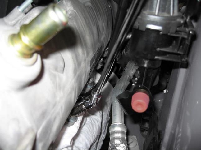
8 20. Unplug then unbolt both the left and right hand camshaft position sensor using an 8 mm socket. 21. Using the breaker bar and 15mm deep socket loosen both cam phaser bolts but don t remove it completely. Try to loosen the bolts without the engine turning. Use the breaker bar with a socket on the balancer to hold the engine in place if necessary. 22. After both cam phaser bolts have been broken loose the timing chain wedge/ hose can be inserted down in between the timing chain and engine block. Note: If using the timing wedge the curved part will face down for the passenger s side and up for the driver s side.


9 23. We will begin the process on the passenger s side camshaft first. Insert the wedge or folded in half hose as shown. Push hard to wedge the piece into place. The goal is to prevent any movement of the chain. You should be able to tug gently on the wedge or hose without it coming loose. Do not remove this wedge until after this side of the cam install has been completed. Removing the stock camshafts

10 1. After you are sure that the chain will not move, mark both the chain and cam phaser sprocket with a sharpie or marker. This will ensure that the chain can be relocated in the correct tooth if the sprocket and chain separate. 2. Using an 8mm socket, loosen the Camshaft bearing caps slowly in this order. Note: Since we have not removed the followers the cam needs to be evenly and slowly release pressure off of the valve springs. To do this multiple passes of the loosing order will be completed. Only a couple turns per bolt until all the bolts can be removed at the same time. 3. While the bolts are loose but still in place, remove the bolts for the front bearing cap first and pull off the cap and set aside. Now continue to remove the rest of the bolts and caps. Set the caps in correct order and direction. All caps have an arrow which points forward and an accompany number.


11 4. With all the camshaft bearing caps removed we can now unbolt the cam phaser bolt from the sprocket. Make sure not to allow the sprocket to fall out of place. 5. Once the old bolt has been removed discard the bolt as it is a one-time use bolt. Tip the end of the cam closet to the firewall upwards. At the same time lift the cam phaser sprocket. This will allow you to easily slide out the cam from the sprocket. 6. With the cam removed check to see that all of the roller followers are still aligned and in place. These are just resting and are easy to become misaligned or fall out of place. If they happen to fall off they can be placed back to their original position by sliding the open end over the pin of the spring and resting the concave area over the lash post.

12 7. Once all the followers are aligned take some cam install oil and apply to the followers and the lower cam bearings. 8. After oil has been applied you are ready to install the new camshaft. First you must make sure the new camshaft is free of debris. Wipe with a rag and new motor oil. The cams have been pre-oiled to prevent rust but this layer can hold in dirt and small metal pieces from the machining process. Installing the new Camshafts 1. Now that the new cam is clean we can set it into place. The install process will be similar to the removal process. Each side has a different length cam match the length of the new cam to the old one to know which side is which. When placing them next to each other match the ends, one cam will be longer than the other. 2. First hold the sprocket at an angle and take note of where the hole is. Looking at the cam locate the pin. When installing the cam, make sure the pin locks into the hole of the sprocket. Slide the cam into the sprocket; twist the cam until you are confident the pin is in the hole. 3. Obtain a new cam phaser bolt and loosely install it to hold the cam and sprocket together. 4. Take the bearing caps and loosely tighten them, slowly bringing the cam into place. Make sure the lobs of the cam are centered on their respective followers. 5. Take the first cam bearing cap and check to make sure the oil grove is clear and clean. Place the bearing cap on the cam and make sure the disk on the cam fits into the slot of the bearing cap. Make sure that the cap will seat properly. If necessary loosen the other bearing caps and slide the cam until the first bearing cap fits into place. Note when sliding cam the followers may tend to fall off. Refer to Step 6 of Removing the Stock Camshaft to reinstall them correctly.

13 6. Add more cam install oil to the entire length of the cam and adding more to the sections without lobes where the bearing caps will be placed. 7. Once you are sure the first cap will fit tighten the other bearing caps in order to evenly bring the cam to the followers. Only tighten until the bearing caps are resting on the lower bearings. Be sure the bearing caps are even when being pulled down. 8. Go back and check that all bearing cap bolts are sung. Then set the torque wrench to 89in-lbs. This is a low torque setting so make sure not to miss the click of the wrench and over tighten the bolts. 9. Once all the bolts have been tightened take the larger torque wrench and tighten the phaser bolt to 30ftlbs. Be careful not to turn the engine or pull the timing chain wedge further into the engine. After the bolt has been torqued to 30ftlbs you will have to turn the bolt an additional 90 degrees. To ensure you do not overtorque the bolt, mark the socket and the sprocket with a line, then mark the sprocket an additional 90 degrees. Turn the socket until the mark on the socket meets the 2nd mark at 90 degrees. If needed use a breaker bar to turn the 90 degrees.

14 10. We can now remove the timing chain wedge. 11. Once the wedge is removed you can repeat the stock cam removal and install on the other side following the same steps and procedures. Remember to install the wedge on the other side as well. Reinstalling the Valve Covers 1. After both cams have been installed you can place the valve covers back on and retighten. 2. First we will apply gasket paste to reinsure a good seal and that no oil will leak. Just a little dab around this black square is all that is needed.


15 3. Clean the original gasket with a rag and new motor oil. Place the gasket firmly into the valve covers. 4. Place the covers back over the cams and onto the block. Tighten all bolts in the following order. Note the #14 bolt on the driver s side is a threaded stud. Torque all valve cover bolts to 89in-lbs.
16 5. Bolt in the cam sprocket position senor. Re-attach the wire connection. Push in the coilpacks and bolt in and torque to 89in-lbs. Re-attach all wire supports. Reconnect MAF and all PCV connections. 6. Double check that all connections are complete. Then reinstall battery tray and then place in battery. Connect battery; positive first then negative. 7. Turn on car but don t start motor. At this time your custom tune can be loaded. 8. Once tune upload is complete, start the engine and check for leaks. There may be some smoke from oil dripped on to the manifolds/headers from when the valve covers were removed. Check the engines oil pressure. Turn off engine if there are any grinding noises. Cam Break-in Cycle 1. After the cams have been installed they need to be properly broken in to wear properly and be durable. 2. After the engine is started and you are confident there are no instant problems, drive the car for at least a half hour keeping the revs between 2500 and 3000rpm. Every so often bring the rpms up to 3500 to spread oil over the new cams. After the first 10 minutes, with the engine still running, pull over and check again for any leaks or problems. I found the best way to do this is to drive around staying only in 1st and 2nd gear. After your test drive you can turn off the car and again check that there are no problems. It is better to catch a small problem now to prevent it becoming a larger problem later. Now you can enjoy the great lopey sound and the power increase of your new FRPP Hot Rod cams. This guide applies to Vehicle years: 2005, 2006, 2007, 2008, 2009, 2010 and Submodels: Bullitt, GT
Ford Racing Hot Rod Performance Camshafts (05-10 GT)
") Time Necessary: 8 hours Tools Required: Ford Racing Hot Rod Performance Camshafts (05-10 GT) 10mm deep socket 11mm socket 8 mm deep socket 15 mm deep socket 18 mm deep socket Universal Joint socket (articulated
Time Necessary: 8 hours Tools Required: Ford Racing Hot Rod Performance Camshafts (05-10 GT) 10mm deep socket 11mm socket 8 mm deep socket 15 mm deep socket 18 mm deep socket Universal Joint socket (articulated
Ford Racing Performance Improvement Intake Manifold (96-04 GT) Time Necessary: Approximately 4 hours
 Time Necessary: Approximately 4 hours") Ford Racing Performance Improvement Intake Manifold (96-04 GT) Time Necessary: Approximately 4 hours Tools Required: Ratchet and socket set Torque wrench Large adjustable wrench Needle nose pliers A dozen
Ford Racing Performance Improvement Intake Manifold (96-04 GT) Time Necessary: Approximately 4 hours Tools Required: Ratchet and socket set Torque wrench Large adjustable wrench Needle nose pliers A dozen
DrVanos.com Stage II Installation Instructions. Tool rental is available with the purchase of a vanos kit *See website for more info*
 DrVanos.com Stage II Installation Instructions Special Tools Needed: Camshaft locking tool TDC Crank pin Sprocket turning tool Tool rental is available with the purchase of a vanos kit *See website for
INSTALLATION INSTRUCTIONS
 N-MT13-1 & N-MT13-2 COLD AIR INTAKE KIT INSTALLATION INSTRUCTIONS MUSTANG GT 2015-up PARTS INCLUDED Part Number Descrip on Qty 9-SA-INTAKE-100 Intake Assembly 1 9-SA-HEATSHIELD-100 Heatshield Assembly
 Special Tools Needed: DrVanos.com Stage I Installation Instructions Camshaft locking tool TDC Crank pin Sprocket turning tool Tool rental is available with the purchase of a vanos kit *See website for
Ford Racing Laser Etched Valve Covers (05-10 GT, GT500)
") Applicable Part Numbers: M-6582-FR3VBL (Blue) M-6582-FR3VBLK (Black) M-6582-C543V (Chrome) List of Tools: 1/4 ratchet 3/8 ratchet 8mm socket 10mm socket 7mm socket 1/4 & 3/8 extensions Plastic gasket scraper
Applicable Part Numbers: M-6582-FR3VBL (Blue) M-6582-FR3VBLK (Black) M-6582-C543V (Chrome) List of Tools: 1/4 ratchet 3/8 ratchet 8mm socket 10mm socket 7mm socket 1/4 & 3/8 extensions Plastic gasket scraper
JBA Cat4ward Shorty Header Install (05-10 Mustang GT and Bullitt)
") JBA Cat4ward Shorty Header Install (05-10 Mustang GT and 08-09 Bullitt) Installation Time: 6-8 Hours (Depending on Tools and Help) Tools Required: 8mm Socket 10 mm Socket 13mm Socket 15mm Deep Socket Ratchet
JBA Cat4ward Shorty Header Install (05-10 Mustang GT and 08-09 Bullitt) Installation Time: 6-8 Hours (Depending on Tools and Help) Tools Required: 8mm Socket 10 mm Socket 13mm Socket 15mm Deep Socket Ratchet
 Page 1 of 21 303-01C Engine 5.4L (3V) 2009 F-150 REMOVAL Procedure revision date: 03/26/2009 Cylinder Head Special Tool(s) 3 Jaw Puller 303-D121 or equivalent Compressor, Valve Spring 303-1039 Holding
2017 Current Ford Raptor Stealth Fighter Rear Bumper Installation Instructions
 2017 Current Ford Raptor Stealth Fighter Rear Bumper Installation Instructions PREPARATION 1. Disconnect the negative terminal on the battery. Park the vehicle on level ground and set the emergency brake.
2015+ HELLCAT 6.2L HEMI System vehicle specific plate system xx
 These installation instructions will guide you through installing the Nitrous Outlet 2015+ Hellcat 6.2L Hemi Vehicle Specific Plate System on your vehicle. Before you get started, remember to never use
Ford Focus Zetec SVT Timing Belt
 2000-2004 Ford Focus Zetec SVT Timing Belt Replacement This guide will show you how to replace the timing belt on the 2.0L DOHC Zetec with VCT on a 2002 Ford Focus SVT. This is an interference motor. Written
Steeda Billet Charge Motion Control Plates (05-08 GT) - Installation Instructions
 - Installation Instructions") Steeda Billet Charge Motion Control Plates (05-08 GT) - Installation Instructions The below installation instructions work for the following products: Steeda Billet Charge Motion Control Plates (05-08
Steeda Billet Charge Motion Control Plates (05-08 GT) - Installation Instructions The below installation instructions work for the following products: Steeda Billet Charge Motion Control Plates (05-08
Weistec M156/M159 ENGINE
 Weistec M156/M159 ENGINE Oil / Air Separator System Installation Guide 2007-2011 S63 AMG 2007-2011 ML63 AMG 2007 R63 AMG 2007-2008 CLK63 AMG 2008 CLK63 Black Series 2007-2011 CLS63 AMG 2008-Present C63
L Intake Manifold Part #
 86-93 5.0L Intake Manifold Part #5001-5002 I N S T A L L A T I O N I N S T R U C T I O N S Supplied Materials Bottom cover, Upper manifold, Lower manifold, Plenum cover plate, 1501 Throttle body (comes
Pypes Polished Shorty Headers (05-10 V6):
:") Pypes Polished Shorty Headers (05-10 V6): Introduction: The kit comes complete with replacement hardware and gaskets and can be easily done in your driveway. The hardware supplied for install includes
Pypes Polished Shorty Headers (05-10 V6): Introduction: The kit comes complete with replacement hardware and gaskets and can be easily done in your driveway. The hardware supplied for install includes
Cylinder Head. Special Tool(s) 3-Jaw Puller 303-D121 or equivalent. Compressor, Valve Spring
 3-Jaw Puller 303-D121 or equivalent. Compressor, Valve Spring") SECTION 303-01B: Engine 4.6L (3V) 2009 Mustang Workshop Manual REMOVAL Procedure revision date: 03/15/2009 Cylinder Head Special Tool(s) 3-Jaw Puller 303-D121 or equivalent Compressor, Valve Spring 303-1039
SECTION 303-01B: Engine 4.6L (3V) 2009 Mustang Workshop Manual REMOVAL Procedure revision date: 03/15/2009 Cylinder Head Special Tool(s) 3-Jaw Puller 303-D121 or equivalent Compressor, Valve Spring 303-1039
BBK Intake Manifold Kit ( L) - Installation Instructions
 - Installation Instructions") BBK Intake Manifold Kit (86-93 5.0L) - Installation Instructions The below installation instructions work for the following products: BBK Intake Manifold Kit (86-93 5.0L) Please read through the instructions
BBK Intake Manifold Kit (86-93 5.0L) - Installation Instructions The below installation instructions work for the following products: BBK Intake Manifold Kit (86-93 5.0L) Please read through the instructions
2017 Current Ford Raptor HoneyBadger Rear Bumper Installation Instructions
 2017 Current Ford Raptor HoneyBadger Rear Bumper Installation Instructions PREPARATION 1. Disconnect the negative terminal on the battery. Park the vehicle on level ground and set the emergency brake.
REMOVAL. Cylinder Head. All cylinder heads. 1. Remove the engine. For additional information, refer to Engine in this section.
 303-01B-1 303-01B-1 REMOVAL Cylinder Head Material Item Specification Special Tool(s) Motorcraft Metal Surface Prep Modular Engine Lift Bracket ZC-31 303-F047 (014-00073) or equivalent Silicone Gasket
COBB CAMSHAFTS INSTALLATION Impreza RS/TS
 4673 South Cherry St. Salt Lake City, UT 84213 USA +1 801-713-0035 COBB CAMSHAFTS INSTALLATION 99-01 Impreza RS/TS Congratulations on your purchase of Cobb Camshafts. The following instructions should
M7 R52S & R53 Cold Air Intake Installation Guide 53-3M7301
 M7 R52S & R53 Cold Air Intake Installation Guide 53-3M7301 M7 Speed engineers and manufactures the highest quality MINI COOPER accessories and performance parts available anywhere on Planet Earth! Please
Installation Instructions
 Installation Instructions Transverse K04 Tools Required Jack and jack stands Drain pan for coolant and oil 3" and 6" extensions Channel locks 7mm, 8mm, 10mm, 11mm, 12mm, 13mm, and 16mm sockets Oxygen sensor
Remove Air Cleaner Cover and. Filter
 Remove Air Cleaner Cover and Inspect paper filter for tears Foam pre-cleaner is washable if equipped Replace if necessary Filter Remove Trim Panel Pull throttle lever knob off Remove 3, 8mm screws Remove
REMOVAL & INSTALLATION
 REMOVAL & INSTALLATION NOTE: For reassembly reference, label all electrical connectors, vacuum hoses and fuel lines before removal. Also place mating marks on engine hood and other major assemblies before
Procharger Stage II Intercooled Supercharger System (11-14 GT)
") Procharger Stage II Intercooled Supercharger System (11-14 GT) Installation Time: Approximately one day. Installed on 2012 Mustang GT 5.0/Manual Required Tools 3/8 Socket Set (Standard and Metric) 1/2
Procharger Stage II Intercooled Supercharger System (11-14 GT) Installation Time: Approximately one day. Installed on 2012 Mustang GT 5.0/Manual Required Tools 3/8 Socket Set (Standard and Metric) 1/2
C&L Upper Intake Plenum (96-04 GT):
:") C&L Upper Intake Plenum (96-04 GT): Tools Needed: Flat-Head Screwdriver 10mm Socket 5/16 Socket 1/4 or 3/8 Ratchet 2 Ratchet Extension Time Required: Approximately 1 hour Installation Instructions: 1.
C&L Upper Intake Plenum (96-04 GT): Tools Needed: Flat-Head Screwdriver 10mm Socket 5/16 Socket 1/4 or 3/8 Ratchet 2 Ratchet Extension Time Required: Approximately 1 hour Installation Instructions: 1.
Technical Service BULLETIN
 Technical Service BULLETIN May 19, 2003 Title: Models: 00 02 Celica GTS EG010-03 ENGINE Introduction In some cases, owners of 2000 2002 model year Celica GTS vehicles equipped with the 2ZZ GE engine may
Exhaust Heat Shield Instructions ND
 Exhaust Heat Shield Instructions ND 2016 + Thank you for purchasing the Track Dog Racing Exhaust Heat Shield for the 2016 to Present Mazda MX-5. Our TDR Heat Shield is designed to help maintain lower temperatures
Ford Racing GT500 Style Strut Mount Upgrade (05-12 All):
:") Ford Racing GT500 Style Strut Mount Upgrade (05-12 All): Required tools: (2) Jack stands Floor jack (1 is required but 2 is preferred) Torque wrench Spring compressor tool (can be rented at your local
Ford Racing GT500 Style Strut Mount Upgrade (05-12 All): Required tools: (2) Jack stands Floor jack (1 is required but 2 is preferred) Torque wrench Spring compressor tool (can be rented at your local
These instructions were written for reference only and the use of a factory service manual is recommended.
 Introducing the CorkSport High Pressure Fuel Line designed for the MZR DISI. This fuel line is designed to replace the OEM fuel line which are prone to failure at the brazed connection at the rail. The
Engine. Special Tool(s) Adapter for (T97T-6256-A) Adapter for (T97T-6256-D)
 Adapter for (T97T-6256-A) Adapter for (T97T-6256-D)") SECTION 303-01A: Engine 4.0L SOHC 2009 Mustang Workshop Manual ASSEMBLY Procedure revision date: 05/10/2010 Engine Special Tool(s) Adapter for 303-564 303-578 (T97T-6256-A) Adapter for 303-577 303-576
SECTION 303-01A: Engine 4.0L SOHC 2009 Mustang Workshop Manual ASSEMBLY Procedure revision date: 05/10/2010 Engine Special Tool(s) Adapter for 303-564 303-578 (T97T-6256-A) Adapter for 303-577 303-576
DISASSEMBLY. Engine. Special Tool(s) Locking Tool, Camshaft Phaser Sprocket Special Tool(s)
 Locking Tool, Camshaft Phaser Sprocket Special Tool(s)") 303-01B-1 DISASSEMBLY Engine Special Tool(s) Remover, Crankshaft Rear Slinger 303-514 (T95P-6701-AH) Special Tool(s) 303-01B-1 Locking Tool, Camshaft Phaser Sprocket 303-1046 Remover, Crankshaft Rear Seal
303-01B-1 DISASSEMBLY Engine Special Tool(s) Remover, Crankshaft Rear Slinger 303-514 (T95P-6701-AH) Special Tool(s) 303-01B-1 Locking Tool, Camshaft Phaser Sprocket 303-1046 Remover, Crankshaft Rear Seal
SR Performance Twin 62mm Throttle Body for GT
 Required Tools: SR Performance Twin 62mm Throttle Body for 2005-2010 GT Flat-head screwdriver Ratchet Small extension 10mm socket 8mm socket T20 Torx bit Needle nose pliers 5mm allen wrench Recommended
INSTALLATION INSTRUCTIONS
 PERFORMER RPM CAMSHAFT / LIFTERS / LUBE KIT For 343-401 c.i.d. AMC V8 Engines CATALOG # 7132 INSTALLATION INSTRUCTIONS PLEASE study these instructions carefully before beginning this installation. Most
M52tu-M54 VANOS Assembly & Timing Using G.A.S. Professional Cam Tool Kit
 Home BMW Solutions Porsche Solutions DIY Tech Engine Services Dyno Services Machining About Contact Store Tool Rental M52tu-M54 VANOS Assembly & Timing Using G.A.S. Professional Cam Tool Kit This procedure
These instructions were written for reference only and the use of a factory service manual is recommended.
 Introducing the CorkSport High Pressure Fuel Line designed for the MZR DISI. This fuel line is designed to replace the OEM fuel line which are prone to failure at the brazed connection at the rail. The
Ford Racing SVT Performance Cooling Fan (05-14 GT, GT500)
") Ford Racing SVT Performance Cooling Fan (05-14 GT, GT500) Time Necessary: Approximately 60-90 minutes Tools Required: 8mm wrench 8mm socket (3/8 drive, optional) 10mm socket (3/8 drive) 10mm deep socket
Ford Racing SVT Performance Cooling Fan (05-14 GT, GT500) Time Necessary: Approximately 60-90 minutes Tools Required: 8mm wrench 8mm socket (3/8 drive, optional) 10mm socket (3/8 drive) 10mm deep socket
Included parts: 1 - New Bosch CP3 Pump 1 - HSM Pulley 1 - Serpentine Belt 1 - Pump Bracket/ Hardware STEP 1
 TROUBLESHOOTING: Please read and understand all installation instructions before proceeding with the installation. If you have questions during the installation of this product, please contact H&S Motorsports
Performance Air Intake, 2015+
 PARTS LIST AND PARTS LIST 1PC ALUMINUM INTAKE PIPE 1PC HIGH-FLOW, OILED AIR FILTER 1PC SILICONE INDUCTION HOSE 1PC AIRBOX 1PC 1/16 RUBBER STRIPPING, 9 LENGTH 1PC 1/16 RUBBER STRIPPING, 8.5 LENGTH 1PC WORM-GEAR
RFI COLD AIR INTAKE INSTALLATION MANUAL. Ford 6.2L F250-F Not legal for sale or use in California on pollution-controlled vehicles.
 INSTALLATION MANUAL Applications RFI Part Number Ford 6.2L F250-F350 2011+ 51204-99 Not legal for sale or use in California on pollution-controlled vehicles. Introduction This manual provides step-by-step
Installation Instructions Camaro ZL1 ( Z) ( ZB)
 ( ZB)") Installation Instructions Camaro ZL1 (501-1099-10-Z) (501-1099-10-ZB) Parts List 1 Insulated Air Box \ Lid 1 Thermal Coated Intake Tube / MAF Housing with (2) M4 x.7 thread 8mm long Stainless Screws; 1
Installation Instructions Camaro ZL1 (501-1099-10-Z) (501-1099-10-ZB) Parts List 1 Insulated Air Box \ Lid 1 Thermal Coated Intake Tube / MAF Housing with (2) M4 x.7 thread 8mm long Stainless Screws; 1
Thank you for purchasing the Dezod Motorsports Return Fuel System for your Scion tc.
 Thank you for purchasing the Dezod Motorsports Return Fuel System for your Scion tc. We took much pride in putting together a fuel system that would deliver a maximum amount of fuel as simply as possible
SLP Camaro ZL1 STAGE 3 (650 HP)
") SLP - 2012 Camaro ZL1 STAGE 3 (650 HP) PART #26002 PACKING LIST Before installation, use this check list to make sure all necessary parts have been included. ITEM QTY CHECK PART NUMBER DESCRIPTION 1. 1
SLP - 2012 Camaro ZL1 STAGE 3 (650 HP) PART #26002 PACKING LIST Before installation, use this check list to make sure all necessary parts have been included. ITEM QTY CHECK PART NUMBER DESCRIPTION 1. 1
CBEA/CJAA Timing belt procedure. Written by: greengeeker Photos by: DanG144, Kriesel, coalminer16. Required tools:
 CBEA/CJAA Timing belt procedure Written by: greengeeker Photos by: DanG144, Kriesel, coalminer16 Required tools: Securing pin 3359 (need two of them!) Crankshaft stop T10050 Counter-hold tool T10172 Special
Integrated Engineering MK7 & MQB Catch Can Kit Install
 Integrated Engineering MK7 & MQB Catch Can Kit Install Thank you for purchasing another high quality Integrated Engineering product! This instruction guide is used for installation of Integrated Engineerings
Long Tube Header Installation For Ford Mustang GT
 Long Tube Header Installation For 2005-2008 Ford Mustang GT Precision manufactured using aircraft quality T-304 stainless steel; this system is designed to endure years of heavy use. Installing a Borla
Stack Racing 70mm Throttle Body for Ford Mustang 5.0 (GT, Cobra)
") Stack Racing 70mm Throttle Body for 1994-1995 Ford Mustang 5.0 (GT, Cobra) Installation Time: Approximately 1 hour Tools Required: Flat head screwdriver Phillips head screwdriver ¼ or 3/8 ratchet 6-9 extension
Stack Racing 70mm Throttle Body for 1994-1995 Ford Mustang 5.0 (GT, Cobra) Installation Time: Approximately 1 hour Tools Required: Flat head screwdriver Phillips head screwdriver ¼ or 3/8 ratchet 6-9 extension
Depress each tab as you pull the bezel off. The bezels are tight. L.H. shown.
 2013-2014 Ford Mustang V6 & Boss 302 Lower Valance Fog Light Kit Parts List: Quantity: Tool List: Fog light & bulb with bracket 2 Flat head & Phillips screwdriver Black bezels 2 Ratchet & Socket set OR
Included parts: 1 - BorgWarner SX-E Turbocharger 1 - SX-E 90-Degree Compressor Outlet Elbow 1 - HSM Cast Exhaust Manifold 1 - HSM Downpipe
 TROUBLESHOOTING: Please read and understand all installation instructions before proceeding with the installation. If you have questions during the installation of this product, please email H&S Motorsports
PERFORMER RPM Camshaft/Lifters/Lube Kit CATALOG #7102 MODEL: c.i.d. Chevrolet V8, 1957 & later
 PERFORMER RPM Camshaft/Lifters/Lube Kit CATALOG #7102 MODEL: 262-400 c.i.d. Chevrolet V8, 1957 & later PLEASE study these instructions carefully before installing your new camshaft. If you have any questions
APR, LLC 1027-B Opelika Road Auburn Alabama 36830
 B6 A4 INJECTOR INSTALLATION L A T I N Tool Needed: - Flathead Screwdriver (large) - Flathead Screwdriver (small) - Ratchet - 5mm Allen Socket If you are using the APR Injectors, you will also need the
Long Tube Header Installation PNs , 17276
 Long Tube Header Installation PNs - 17260, 17276 ***** Please compare the parts in the box with the bill of materials provided ***** to assure that you have all the parts necessary for this installation.
C&L Cold Air Intake (05-09 V6) - Installation Instructions
 - Installation Instructions") C&L Cold Air Intake (05-09 V6) - Installation Instructions The below installation instructions work for the following products: C&L Cold Air Intake (05-09 V6) Please read through the instructions carefully
C&L Cold Air Intake (05-09 V6) - Installation Instructions The below installation instructions work for the following products: C&L Cold Air Intake (05-09 V6) Please read through the instructions carefully
ASSEMBLY. Engine. Special Tool(s) Installer, Crankshaft Vibration Damper (T74P-6316-B) Special Tool(s)
 Installer, Crankshaft Vibration Damper (T74P-6316-B) Special Tool(s)") 303-01A-1 ASSEMBLY Engine Special Tool(s) Tensioner, Timing Chain 303-571 (T97T-6K254-A) Special Tool(s) 303-01A-1 Installer, Crankshaft Vibration Damper 303-102 (T74P-6316-B) Holding Tool, Camshaft Sprocket
303-01A-1 ASSEMBLY Engine Special Tool(s) Tensioner, Timing Chain 303-571 (T97T-6K254-A) Special Tool(s) 303-01A-1 Installer, Crankshaft Vibration Damper 303-102 (T74P-6316-B) Holding Tool, Camshaft Sprocket
Procedure: Installation of the ATP Eliminator Series turbo hardware kit for the 1.8T B5/B6 Audi A4/VW Passat Years 1996 through 2005.
 ADVANCED TUNING PRODUCTS, INC Page 1 of 13 Procedure: Installation of the ATP Eliminator Series turbo hardware kit for the 1.8T B5/B6 Audi A4/VW Passat Years 1996 through 2005. Parts Checklist (Bill Of
2002 Mustang Workshop Manual
 Page 1 of 13 SECTION 303-01B: Engine 4.6L (2V) 2002 Mustang Workshop Manual REMOVAL Procedure revision date: 01/02/2003 Cylinder Heads Special Tool(s) Remover, Crankshaft Vibration Damper 303-009 (T58P-6316-D)
Installation Instructions and Warranty Information
 Corporate Office: PerTronix Inc. 440 E. Arrow Highway, San Dimas, California 91773 * Phone 909.599.5955 FAX 909.599.6424 Installation Instructions and Warranty Information 6695S 2007-14 5.4/5.8 Ford Mustang
7 th Gen. Celica GTS Turbo Kit Installation Guide This kit has not been CARB approved and is intended for racing / offroad purposes only.
 7 th Gen. Celica GTS Turbo Kit Installation Guide This kit has not been CARB approved and is intended for racing / offroad purposes only. The purpose of this guide is to serve as a reference for use when
COBB SF SHORT RAM INTAKE SYSTEM MazdaSpeed3
 COBB SF SHORT RAM INTAKE SYSTEM MazdaSpeed3 Congratulations on your purchase of the COBB Tuning SF Intake System. The following instructions should assist you through your installation process. Please
Ford Mustang GT Long Tube Header Installation
 2005-2006 Ford Mustang GT Long Tube Header Installation Precision manufactured using aircraft quality T-304 stainless steel; this system is designed to endure years of heavy use. Installing a Borla Performance
Engine. Special Tool(s) Compressor, Piston Ring 303-D032 (D81L-6002-C) or equivalent. Compressor, Valve Spring (T93P-6565-AR)
 Compressor, Piston Ring 303-D032 (D81L-6002-C) or equivalent. Compressor, Valve Spring (T93P-6565-AR)") SECTION 303-01C: Engine 5.4L (4V) 2009 Mustang Workshop Manual ASSEMBLY Procedure revision date: 12/12/2008 Engine Special Tool(s) Compressor, Piston Ring 303-D032 (D81L-6002-C) or equivalent Compressor,
SECTION 303-01C: Engine 5.4L (4V) 2009 Mustang Workshop Manual ASSEMBLY Procedure revision date: 12/12/2008 Engine Special Tool(s) Compressor, Piston Ring 303-D032 (D81L-6002-C) or equivalent Compressor,
GenX Street/Strip Cylinder Heads for the GM LT1
 GenX Street/Strip Cylinder Heads for the GM LT1 Thank you for purchasing Trick Flow GenX Street/Strip aluminum cylinder heads for the GM LT1. Please follow the steps outlined in this instruction manual
PERFORMER RPM Camshaft/Lifters/Lube Kit CATALOG #7102 MODEL: c.i.d. Chevrolet V8, 1957 & later
 PERFORMER RPM Camshaft/Lifters/Lube Kit CATALOG #7102 MODEL: 262-400 c.i.d. Chevrolet V8, 1957 & later CAMSHAFT: Edelbrock Performer RPM camshafts are ground specifically for use with the corresponding
Turner M50 Manifold Adapter Install. April 26, 2012
 April 26, 2012 Models: 1996-99 E36 328i/M3; 1997-98 E39 528i, 1997-98 Z3 2.8, 1998-2000 MZ3 S52 Product(s): Turner M50 Manifold Adapter Kit Subject: Installation Guidelines and Tips This guide will aid
Cylinder Head. Special Tool(s) Compressor, Valve Spring (T93P-6565-AR) Heavy Duty Floor Crane or equivalent
 Compressor, Valve Spring (T93P-6565-AR) Heavy Duty Floor Crane or equivalent") SECTION 303-01C: Engine 5.4L (4V) 2009 Mustang Workshop Manual INSTALLATION Procedure revision date: 04/03/2009 Cylinder Head Special Tool(s) Compressor, Valve Spring 303-452 (T93P-6565-AR) Heavy Duty
SECTION 303-01C: Engine 5.4L (4V) 2009 Mustang Workshop Manual INSTALLATION Procedure revision date: 04/03/2009 Cylinder Head Special Tool(s) Compressor, Valve Spring 303-452 (T93P-6565-AR) Heavy Duty
Instant Chat off the main page of Or simply call our tech team at
 Adjustable Fuel Pressure Regulator Kit for 2008+STI 2018-10-03 PSP-FUL-301 Thank you for purchasing this PERRIN product for your car! Installation of this product should only be performed by persons experienced
Equipped with AEM Dryflow Filter No Oil Required! INSTALLATION INSTRUCTIONS PART NUMBER C (GUN METAL GRAY FINISH) NISSAN SENTRA 1.
 NISSAN SENTRA 1.") Equipped with AEM Dryflow Filter No Oil Required! INSTALLATION INSTRUCTIONS PART NUMBER 21-799C (GUN METAL GRAY FINISH) 2014-16 NISSAN SENTRA 1.8L 1 ITEM NO. PART NUMBER DESCRIPTION QTY. 1 21-2157D AIR
Equipped with AEM Dryflow Filter No Oil Required! INSTALLATION INSTRUCTIONS PART NUMBER 21-799C (GUN METAL GRAY FINISH) 2014-16 NISSAN SENTRA 1.8L 1 ITEM NO. PART NUMBER DESCRIPTION QTY. 1 21-2157D AIR
Valve gear, servicing
 Page 1 of 62 15-1 Valve gear, servicing WARNING! Do not re-use any fasteners that are worn or deformed in normal use. Some fasteners are designed to be used only once, and are unreliable and may fail if
GENERAL INSTRUCTIONS. PERFORMER-PLUS CAMSHAFT / LIFTERS / LUBE KIT MODEL: c.i.d. Chevrolet V8 Engines CATALOG #2117
 Page 1 PERFORMER-PLUS CAMSHAFT / LIFTERS / LUBE KIT MODEL: 283-400 c.i.d. Chevrolet V8 Engines GENERAL INSTRUCTIONS PLEASE study these instructions carefully before beginning this installation. Most installations
Slingshot Rotrex Supercharger Kit
 Slingshot Rotrex Supercharger Kit This supercharger kit improves on the Slingshot by forcing more dense air into the engine and creating more power. Installation time of the supercharger depends on you
FREE $15 Gift Card for every $100 spent on Ship To Home orders. Find Out How
 1 of 29 10/12/2011 5:05 PM FREE $15 Gift Card for every $100 spent on Ship To Home orders. Find Out How Ford Ranger/Explorer/Mountaineer 1991-1999 Intake Manifold REMOVAL & INSTALLATION Print The engines
Edelbrock E-Force Supercharger Part #1538: Dodge 1500 Truck 5.7L V8 HEMI
 Edelbrock E-Force Supercharger Part #1538: 2009-2014 Dodge 1500 Truck 5.7L V8 HEMI 2009-14 Dodge 5.7L Hemi 1500 Truck INTRODUCTION Thank you for purchasing the Edelbrock Supercharger System for the 2009-15
Performer-Plus 5.0L Hydraulic Roller Lifter Camshaft only CATALOG #3722 MODEL: 5.0 Litre Ford V8, 1985 & later INSTRUCTIONS
 Performer-Plus 5.0L Hydraulic Roller Lifter Camshaft only CATALOG #3722 MODEL: 5.0 Litre Ford V8, 1985 & later INSTRUCTIONS PLEASE study these instructions carefully before installing your new camshaft.
IMPORTANT WARRANTY & INSTALLATION INSTRUCTIONS ATTACHED TO ACTIVATE YOUR WARRANTY GO TO: CORSAPERFORMANCE.COM/WARRANTY STOP
 IMPORTANT WARRANTY & INSTALLATION INSTRUCTIONS ATTACHED Please Forward All Attached Information to Consumer Warranty Not Valid Unless Returned to CORSA Performance We ask that you take a few moments to
Engine. Special Tool(s) Compressor, Valve Spring (T97P-6565-AH) Compressor Spacer, Valve Spring (T91P-6565-AH)
 Compressor, Valve Spring (T97P-6565-AH) Compressor Spacer, Valve Spring (T91P-6565-AH)") Page 1 of 41 SECTION 303-01A: Engine 5.4L (2V) 2000 F-Super Duty 250-550/Excursion/F-53 Motorhome Chassis Workshop Manual ASSEMBLY Procedure revision date: 04/04/2003 Engine Special Tool(s) Compressor,
Page 1 of 41 SECTION 303-01A: Engine 5.4L (2V) 2000 F-Super Duty 250-550/Excursion/F-53 Motorhome Chassis Workshop Manual ASSEMBLY Procedure revision date: 04/04/2003 Engine Special Tool(s) Compressor,
Do not have any open flame or heat sources close to the installation
 March 6, 2017 IS# 791 Page 1 of 16 Thank you for purchasing a Transfer Flow, Inc. 50-gallon replacement fuel system for your 2011-16 Ford diesel short bed pickup. This system will fit any 2x4 or 4x4 crew
Equipped with AEM Dryflow Filter No Oil Required! INSTALLATION INSTRUCTIONS PART NUMBER C (Gun Metal Grey Finish) 2015 Ford Mustang 5.
 2015 Ford Mustang 5.") Equipped with AEM Dryflow Filter No Oil Required! INSTALLATION INSTRUCTIONS PART NUMBER 21-745C (Gun Metal Grey Finish) 2015 Ford Mustang 5.0L 1 2 Read and understand these instructions BEFORE attempting
Equipped with AEM Dryflow Filter No Oil Required! INSTALLATION INSTRUCTIONS PART NUMBER 21-745C (Gun Metal Grey Finish) 2015 Ford Mustang 5.0L 1 2 Read and understand these instructions BEFORE attempting
Always wear safety glasses when working on your vehicle.
 90-93 MAZDA MIATA SUPERCHARGER KIT The KraftWerks 90-93 Mazda Miata Supercharger Kit was designed for easy installation. Competent mechanics with the appropriate tools will find the process to be relatively
MAX FLOW FUEL KIT KIA FORTE SX HYUNDAI VELOSTER TURBO INSTALLATION INSTRUCTIONS
 MAX FLOW FUEL KIT KIA FORTE SX 2014+ HYUNDAI VELOSTER TURBO INSTALLATION INSTRUCTIONS Installation: Tools needed: 1/4 or 3/8 drive ratchet Different length extensions 8mm socket / 10mm socket / 12mm socket
Edelbrock Victor II Intake Manifold. For Chrysler 5.7L (Eagle) and 6.1L Gen III HEMI Engines Part #7179
 and 6.1L Gen III HEMI Engines Part #7179") For Chrysler 5.7L (Eagle) and 6.1L Gen III HEMI Engines PLEASE study these instructions carefully before beginning this installation. You should be familiar with and comfortable working on your vehicle.
For Chrysler 5.7L (Eagle) and 6.1L Gen III HEMI Engines PLEASE study these instructions carefully before beginning this installation. You should be familiar with and comfortable working on your vehicle.
PRO RATCHET UNIVERSAL SHIFTER
 Installation Instructions PRO RATCHET UNIVERSAL SHIFTER Fits: GM, Ford and Chryslers w/automatic Transmission See Application Guide for Specific Vehicles Catalog # 80842 WORK SAFELY! For maximum safety,
2017+ L5P Duramax 3 ½ Down Pipe & EGR Fix Kit
 2017+ L5P Duramax 3 ½ Down Pipe & EGR Fix Kit Covers installation of PN s: WCF100630, WCF100829 Note: This Kit is for off road competition use only! Off Road Competition Use Tuning & Exhaust System is
Zoom and Print Options
 Vehicle» Engine, Cooling and Exhaust» Engine» Cylinder Head Assembly» Service and Repair» Procedures» Removal Cylinder Heads http://repair.alldata.com/alldata/article/display.action?componentid=65&itypeid=376&nonstandardid=682956&vehicleid=45317&windowname=maina
TOP FEED FUEL RAIL KIT for WRX
 TOP FEED FUEL RAIL KIT for 2002-14 WRX Thank you for purchasing this PERRIN product for your car! Installation of this product should only be performed by persons experienced with installation of aftermarket
INSTALLATION INSTRUCTIONS BILLET FUEL RAIL KIT
 INSTALLATION INSTRUCTIONS BILLET FUEL RAIL KIT MITSUBISHI LANCER EVOLUTION X Document# 19-0067 Support: info@radiumauto.com WARNING: DON'T SMOKE OR WORK WITH OPEN SPARKS WHILE WORKING ON THE FUEL SYSTEM
Ford 6.7 EGR Delete Kit
 Fits: 2011 12 Powerstroke 6.7L Read instructions thoroughly before proceeding! ***This kit may void factory warranty please check with manufacturer.*** ***This kit is intended for off road use only.***
CBEA/CJAA Timing belt procedure. Written by: greengeeker Photos by: DanG144, Kriesel, coalminer16. Required tools:
 CBEA/CJAA Timing belt procedure Written by: greengeeker Photos by: DanG144, Kriesel, coalminer16 Required tools: 1. Securing pin 3359 (you need two of them!) 2. Crankshaft stop T10050 3. Counter-hold tool
Installation Instructions
 CHEVROLET ENGINE SYSTEM, NON-EMISSION 1967-1987 SMALL BLOCK CHEVROLET Part Number 300-502 CHEVROLET ENGINE SYSTEM, NON-EMISSION 1962-1987 CHEVROLET 302, 327, 350 C.I.D. ENGINES Part Number 300-503-1 Installation
WEIAND STREET WARRIOR INTAKE MANIFOLD P/N s 8125, 8125P, 8126, & 8126P SMALL BLOCK CHEVROLET
 APPLICATIONS: WEIAND STREET WARRIOR INTAKE MANIFOLD P/N s 8125, 8125P, 8126, & 8126P 262-400 SMALL BLOCK CHEVROLET INSTALLATION INSTRUCTIONS The P/N 8125 & 8126 WEIAND STREET WARRIOR series intake manifolds
INSTALLATION MANUAL
 315000 INSTALLATION MANUAL EGR & Cooler Race Kit for 2015+ 6.7L Ford Powerstroke WARNING ONLY install this kit if you are using a tuner that disables the EGR sensors & circuit system. Any product that
RFI COLD AIR INTAKE RAPID FLOW COLD AIR INTAKE INSTALLATION MANUAL WORKS ON: GMC Sierra/Chevrolet Silverado 6.
 RAPID FLOW COLD AIR INTAKE INSTALLATION MANUAL 53207 WORKS ON: GMC Sierra/Chevrolet Silverado 6.0L YEARS: 2016+ i INTRODUCTION This manual provides step-by-step installation instructions for the Bully
Focus ST Carbon Fiber Intake
 791400 - Focus ST Carbon Fiber Intake 791400 COBB Focus ST Carbon Fiber Intake Congratulations on your purchase of the COBB Tuning Carbon Fiber Intake System! The following instructions will assist you
RFI COLD AIR INTAKE INSTALLATION MANUAL. GM Duramax 6.6L LMM Stage 2 RFI
 INSTALLATION MANUAL Applications GM Duramax 6.6L LMM Stage 2 RFI 07.5-10 RFI Part Number 53152 Not legal for sale or use in California on pollution-controlled vehicles. i Introduction This manual provides
R-1125 C HARNESS MOUNT BAR INSTALLATION INSTRUCTIONS Fits C7 Corvette Coupes, including Z06
 R-1125 C HARNESS MOUNT BAR INSTALLATION INSTRUCTIONS Fits C7 Corvette Coupes, including Z06 The R-1125 Harness Mount Bar has been designed and tested to provide a mounting point for the shoulder harness
Kit Part Number:
 Equipped with AEM DRYFLOW Filter No Oil Required! Kit Part Number: 21-682 2008 Chevrolet Cobalt SS CARB EO - D-392-32 2009, Advanced Engine Management, Inc. AEM is a registered trademark of Advanced Engine
PERFORMER-PLUS CAMSHAFT / LIFTERS / LUBE KIT CATALOG # 2103 MODEL: 400 c.i.d. Chevrolet V8 engines GENERAL INSTRUCTIONS
 PERFORMER-PLUS CAMSHAFT / LIFTERS / LUBE KIT CATALOG # 2103 MODEL: 400 c.i.d. Chevrolet V8 engines GENERAL INSTRUCTIONS Please study these instructions carefully before you remove your stock camshaft.
2012 Kia Soul L4 2.0L
 2012 Kia Soul L4 2.0L Vehicle» Engine, Cooling and Exhaust» Engine» Timing Chain» Service and Repair» Repair Procedures» Part 1 Removal Engine removal is not required for this procedure. CAUTION: Use fender
BMW N54 Baffled Oil Catch Can, CCV Side, PARTS LIST AND INSTALLATION GUIDE
 PARTS LIST AND PARTS LIST 1PC APPLICATION-SPECIFIC MOUNTING BRACKET 1PC BLACK, ANODIZED 6061 ALUMINUM CATCH CAN 2PC DIRECT-FIT HOSES, BLACK 2PC PLASTIC BARBED FITTINGS PREPARING FOR INSTALLATION 1. Pull
RFI COLD AIR INTAKE INSTALLATION MANUAL GM 6.6L Duramax LBZ Not legal for sale or use in California on pollution-controlled vehicles.
 INSTALLATION MANUAL Applications RFI Part Number 06-07 GM 6.6L Duramax LBZ 53107 Not legal for sale or use in California on pollution-controlled vehicles. Introduction This manual provides step-by-step
Cylinder head, removing and
 Page 1 of 35 15-2 Cylinder head, removing and installing Note: Replace cylinder head bolts. Always replace self-locking nuts, bolts as well as gaskets and O-rings. After installing a replacement cylinder