B Series 1/2" to 2" 2-Way and 3-Way Bronze Control Valves
|
|
|
- Pearl Wright
- 5 years ago
- Views:
Transcription


1 INSTALLATION AND MAINTENANCE INSTRUCTIONS IM US November 2015 B Series 1/2" to 2" 2-Way and 3-Way Bronze Control Valves 1. Safety 2. Technical details 3. Installation and Commissioning 4. Maintenance 5. Spares
2 1. Safety 1.1 PTFE Within its working temperature range PTFE is a completely inert material, but when heated to its sintering temperature it gives rise to gaseous decomposition products or fumes which can produce unpleasant effects if inhaled. The inhalation of these fumes is easily prevented by applying local exhaust ventilation to atmosphere as near to their source as possible. Smoking should be prohibited in workshops where PTFE is handled because tobacco contaminated with PTFE will during burning give rise to polymer fumes. It is therefore important to avoid contamination of clothing, especially the pockets, with PTFE and to maintain a reasonable standard or personal cleanliness by washing hands and removing any PTFE particles lodged under the fingernails. 1.2 Limiting Conditions Temperature ( F) Saturated steam curve ANSI 250 & NPT Pressure (psig) Do not use product in this area. 2
3 2. Technical details 2.1 Description The B Series is a light industrial bronze valve range for pressure, flow and temperature control of stem, gases and liquids. Available in 2-Way and 3-Way body configuration for modulating control with PM Series pneumatic actuators (electric actuation available on request). For enhanced control, any of the extensive range of Spirax Sarco positioners may be fitted. 2.2 Valve Specifications Body sizes 1/2", 3/4", 1", 1-1/4", 1-1/2", 2" Body material ASTM B62 Connection Screwed NPT Body rating F/ F (ASME B Class 250) Characteristic 2-Way Equal Percentage or Linear 3-Way Linear Rangeability 50:1 Temperature Range -20 to 400 F Metal Seating (standard) ANSI/FCI70-2 Class IV 2-Way Valves Seat Leakage PTFE Soft Seating (optional) ANSI/FCI70-2 Class VI 3-Way Valves Metal Seating ANSI/FCI70-2 Class III 2.3 Actuator Specifications Type Multi-Spring Diaphragm (Single Acting) Air Failure PM200R, PM300R, PM700R: Stem Retract PM200E, PM300E, PM700E: Stem Extend Travel 3/4" Ambient Temperature Range -4 to 212 F Maximum Air Pressure 60 psig Diaphragm Material Nitrile, Fabric Reinforced Spring Cases Steel, Powder Epoxy-Coated with Stainless Steel Fasteners Yoke Cast Iron, Epoxy-Coated Positioner Mounting Namur / IEC PM Air Capacity (scf) PM PM
4 2.4 Spring Identification (inches) Actuator Spring Quantity Inside Diameter Length ID Stripe Color PM Green PM Blue PM Blue with Yellow stripe 2.5 Dimensions and Weights (inches and pounds) Size A B C D Actuator End to Bottom to Centerline Actuator Weight Type End Centerline to Top Diameter 1/2" PM /4" PM " 1-1/4" 1-1/2" 2" PM PM PM PM PM PM PM PM PM PM D C B A 4
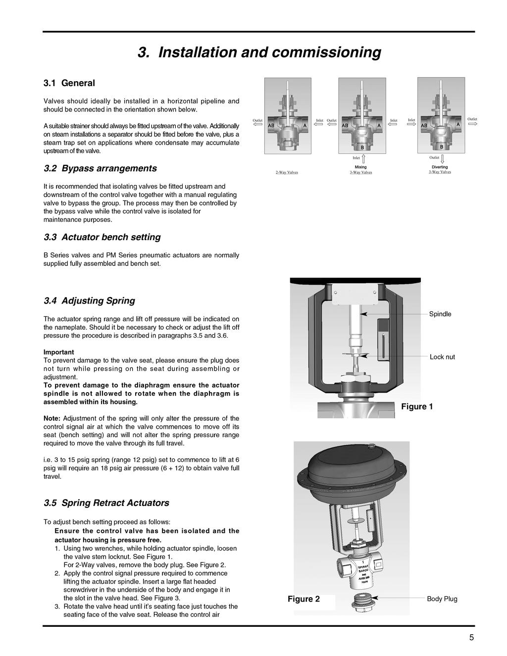
5

6 signal. Using two wrenches, while holding the actuator spindle, tighten the valve stem locknut. Check again that the valve just commences to move off its seat at the right spring range minimum pressure and is fully open at the spring range maximum pressure. 4. If the body plug was removed, apply Loctite 567 to the thread, screw into the body and tighten to a torque of ft/lb. If necessary, adjust the travel indicator plate to align with the travel indicator disc as appropriate. 3.6 Spring Extend Actuators To adjust bench setting proceed as follows: Ensure the control valve has been isolated and the actuator housing is pressure free. 1. Loosen the valve stem locknut and remove the body plug (if applicable) as described in 3.5 above. 2. Apply the control signal that will be used to just close the valve. Insert a large flat head screwdriver in the underside of the body and engage it in the slot in the valve head. See Figure 3. Rotate the valve head until its seating face just touches the seating face on the valve seat. 3. Release the control air signal. Using two wrenches, while holding the actuator spindle, tighten the valve stem locknut. Check again the the valve head moves off its seat at the correct control pressure and that full travel is achieved. 4. If the body plug was removed, apply Loctite 567 to the thread, screw into the body and tighten to a torque of ft/lb. If necessary, adjust the travel indicator plate as appropriate. 3.7 Positioners and Accessories Please refer to the Installation and Commissioning Instructions supplied with the positioner or accessory, if applicable. Valve head adjustment slot. Figure 3 In addition, spindle adaptor # will be required. 4. Maintenance 4.1 Routine maintenance procedures 4.2 Removing actuator from valve 24 hour operation After 24 hours service check pipework connections and flange bolts for tightness. 3 Month operating intervals After every three months of normal service, check gland seals for signs of leakage and replace if necessary. (Refer to Section 4.3, page 7) Annually The valve should be inspected for wear and tear replacing any worn or damaged parts such as valve plug and stem or gland seals. Refer to Section 5 for details of available spares. 1. Isolate the valve on both sides. 2. Using two wrenches, while holding the actuator spindle, loosen the valve stem lock nut (Figure 1). 3. For 2-way valves, remove the body plug (Figure 2). 4. Apply air to the actuator to move the valve head into the mid-travel position approximately. 5. Insert a large, flat headed screwdriver in the underside of the body and engage it in the slot in the valve head (Figure 3). Unscrew the valve head and stem from the actuator spindle until it is fully disengaged. 6. Remove the indicator disc and lock nut from the valve stem and withdraw the valve head and stem from the valve body. 7. Using a 41 mm A/F crows foot type wrench, remove the actuator clamping nut (Figure 4). 8. Remove the actuator from the valve body (Figure 5). 6


.")
7 4.3 Procedure for renewing gland seals and valve head and stem. 1. Remove the actuator from the valve as described in Using a 1" A/F wrench, remove the gland nut from the valve body. Actuator clamping nut 3. Remove and discard the gland seal. 4. Examine parts for signs of damage or deterioration and renew as necessary. Note that score marks or scaly deposits on the valve stem will lead to early failure of the gland seals. 5. Clean parts taking care to avoid scratching the stem or the gland seal housing bore. 6. Remove the grey seal ring and two EPDM o-rings from the gland seal spares pack. Lightly coat the EPDM o-rings with silicon grease and roll them into the two grooves on the seal ring (Figure 6). 7. Insert the seal guide into the valve body, install the gland seal set onto the plunger and liberallly apply silicon grease around the o rings. Insert into the valve body (Figures 7 and 8). Withdraw the plunger and seal guide from the valve body and discard. Figure 4 Figure 5 Figure 6 Plunger Gland seal Seal guide 8. Thread the gland nut into the body and tighten to a torque of 40 ft.lb (Figures 9 and 10). Figure 7 9. Liberally apply silicon grease to the valve stem. Insert the valve head and stem into the bottom of the body and push the stem up through the gland seal taking care not to damage the gland seal with the threads on the stem. 10. Re-mount the actuator onto the valve and screw the clamping nut onto the valve body but do not tighten it. 11. Engage a flat-headed screwdriver in the valve head slot and rotate it until the valve stem threads engage with the actuator spindle threads. The actuator may be moved a very small amount from side to side to ease alignment. Tighten the clamping nut to a torque of 80 ft.lb (Figure 11). The actuator bench setting should now be adjusted in accordance with Section 3.3. Figure 9 Figure 8 Figure 10 Actuator clamping nut 4.4 Replacing spring extend actuator diaphragm, springs and spindle seal. Figure Isolate the valve on both sides. 2. If replacing the spindle seal the actuator should be removed from the valve as described in Remove the diaphragm case screws and upper diaphragm case (Figure 12). Note: take care as the diaphragm case and screws are loaded by the internal springs. 4. Remove springs. Figure 12 7
.")


.")
8 5. Using two wrenches, hold the actuator spindle on the wrench flats and remove the diaphragm clamping nut (Figure 13). Remove diaphragm clamping washers, o-ring and diaphragm. 6. Withdraw the actuator spindle and remove the V ring spindle seal and wiper seal taking care not to damage the spindle bearing (Figure 14). Smear the new V ring and wiper seal with silicon grease and replace. 7. Fit a new diaphragm and reassemble in reverse order. Using two wrenches, hold the actuator spindle on the wrench flats and tighten the diaphragm clamping nut to the torques specified in Table 1. Diaphram clamping nut Figure 13 Spindle Flats 8. While supporting the actuator spindle so that the diaphragm sits evenly in the lower diaphragm case, replace the springs and upper diaphragm case. Replace the diaphragm case screws and nuts and evenly tighten to the torque specified in Table Re-fit the actuator, if necessary, and bench set in accordance with section Replacing spring retract actuator diaphragm, springs and spindle seal. V ring seal Wiper seal Figure Isolate the valve on both sides. 2. If replacing the spindle seal the actuator should be removed from the valve as described in Remove the diaphragm case screws and upper diaphragm case (Figure 15). Note: take care as the diaphragm case and screws are loaded by the internal springs. 4. Using two wrenches, hold the actuator spindle on the wrench flats and remove the diaphragm clamping nut (Figure 16). Remove diaphragm clamping washers, o-ring and diaphragm. 5. Remove springs. 6. Withdraw the actuator spindle and remove the V ring spindle seal and wiper seal taking care not to damage the spindle bearing (Figure 14). Smear the new V ring and wiper seal with silicon grease and replace. 7. Replace springs. 8. Fit a new diaphragm and reassemble in reverse order. Using two wrenches, hold the actuator spindle on the wrench flats and tighten the diaphragm clamping nut to the torques specified in Table While supporting the actuator spindle so that the diaphragm sits evenly in the lower diaphragm case, replace the upper diaphragm case. Replace the diaphragm case screws and nuts and evenly tighten to the torque specified in Table 1. Diaphram clamping nut Figure 15 Figure 16 Spindle Flats Table 1 Recommended tightening torques (ft/lb) Actuator Diaphragm Case Screws Diaphragm clamping nut Series Size Torque Size Torque PM200/300 5/16-18 UNC /2-20 UNC 30 2 PM700 3/8-16 UNC M14 x
9
½" to 4" (DN15 to DN100) LEA31 and LEA33 ANSI Control Valves Installation and Maintenance Instructions
 LEA31 and LEA33 ANSI Control Valves Installation and Maintenance Instructions") 00050/1 IM-P0-02 CH Issue 1 ½" to " (DN15 to DN100) LEA1 and LEA ANSI Control Valves Installation and Maintenance Instructions 1. Safety 2. Technical details. Installation and commissioning. Maintenance
00050/1 IM-P0-02 CH Issue 1 ½" to " (DN15 to DN100) LEA1 and LEA ANSI Control Valves Installation and Maintenance Instructions 1. Safety 2. Technical details. Installation and commissioning. Maintenance
3. Installation and Commissioning 4. Maintenance 5. Spares
 INSTLLTION ND MINTENNCE INSTRUCTIONS IM-P305-06 US November 2003 1/2" to 4" (DN15 to DN100) KE41, 43, 61, 63, 71 and 73 NSI Control Valves 1. Safety 2. Technical details 3. Installation and Commissioning
Types PN5000 and PN6000 Series Pneumatic Actuators Installation and Maintenance Instructions
 3570050/6 IM-P357-04 CH Issue 6 Types PN5000 and PN6000 Series Pneumatic Actuators Installation and Maintenance Instructions 1. General 2. Installation 3. Commissioning 4. Reversal of Actuator Action PN5000
QLM and QLD Series DN125 to DN200 Three Port Control Valves
 3.63.27.22 3900/1 IM-P39-1 CH Issue 1 QLM and QLD Series DN12 to DN200 Three Port Control Valves Installation and Maintenance Instructions 1. Safety information 2. General product information 3. Installation
QLM and QLD Series DN15 to DN100 Three Port Control Valves
 3.563.575.01 3590050/3 IM-P359-01 CH Issue 3 QLM and QLD Series DN15 to DN100 Three Port Control Valves Installation and Maintenance Instructions 1. Safety information. General product information 3. Installation
SPIRA-TROL Two-port Control Valves EN Standard JE, JF and JL DN15 to DN200 and ASME Standard JEA, JFA and JLA ½" to 8"
 3750100/1 IM-S24-61 CH Issue 1 SPIRA-TROL Two-port Control Valves EN Standard JE, JF and JL DN15 to DN200 and ASME Standard JEA, JFA and JLA ½" to 8" Installation and Maintenance Instructions 1. Safety
BBV Automatic or Manually Actuated Boiler Blowdown Valves Installation and Maintenance Instructions DN15 - DN65
 4057050 / 1 IM-P405-54 AB Issue 1 BBV Automatic or Manually Actuated Boiler Blowdown Valves Installation and Maintenance Instructions DN15 - DN65 PN / M automatically actuated 1. Safety information 2.
Control Valves Series "Q" DN15 - DN100 Installation and Maintenace Instructions
 3.563.5275.201 IM-P359-01 CH Issue - 2015 Control Valves Series "Q" DN15 - DN100 Installation and Maintenace Instructions The PED Directive 97/23/EC is repealed and replaced by the new PED Directive 201/68/EU
PN9000 Series Pneumatic Actuators Installation and Maintenance Instructions
 3579049/14 IM-P357-29 CTLS Issue 14 PN9000 Series Pneumatic Actuators Installation and Maintenance Instructions PN9100 PN9200 1. Safety information 2. General product information PN9300 3. Installation
'C' Series Control Valves
 3060050/3 IM-F12-31 CH Issue 3 'C' Series Control Valves Installation and Maintenance Instructions 1. Safety information 2. General product information 3. Installation and Commissioning 4. Maintenance
PN9000 Series Pneumatic Actuators for SPIRA-TROL K and L Series Control Valves
 Description The PN9000 series actuators are a compact range of linear actuators that are available in 3 diaphragm sizes for matching the requirements of valves at various differential pressures. Each actuator
STERI-TROL Clean Service 'S' series Two-port and Three-port Control Valves - DN15 (½") to DN100 (4")
 to DN100 (4)") Page 1 of 17 Cert. No. LRQ 09608 ISO 9001 STERI-TROL Clean Service 'S' series Two-port and Three-port Control Valves - DN15 (½") to DN100 (4") TI-P183-02 CH Issue 3 Description STERI-TROL 'S' series are
Page 1 of 17 Cert. No. LRQ 09608 ISO 9001 STERI-TROL Clean Service 'S' series Two-port and Three-port Control Valves - DN15 (½") to DN100 (4") TI-P183-02 CH Issue 3 Description STERI-TROL 'S' series are
SPIRA-TROL 1/2" to 4" ANSI Two-port KEA, KFA and KLA Control Valves
 1/2" to 4" ANSI Two-port KEA, KFA and KLA Description SPIRA-TROL is a range of two-port single seat globe valves with cage retained seats conforming to ASME/ANSI standards. These valves are available in
SPIRA-TROL 1/2" to 4" ANSI Two-port LEA, LFA and LLA Control Valves
 1/2" to 4" ANSI Two-port LEA, LFA and LLA Description SPIRA-TROL is a range of two-port single seat globe valves with cage retained seats conforming to ASME/ANSI standards. These valves are available in
Fisher 657 Diaphragm Actuator Sizes and 87
 Instruction Manual 657 Actuator (30-70 and 87) Fisher 657 Diaphragm Actuator Sizes 30 70 and 87 Contents Introduction... 1 Scope of Manual... 1 Description... 2 Specifications... 2 Installation... 3 Mounting
Two port valves. pneumatically actuated
 Two port valves pneumatically actuated One valve - The Spirax Sarco range of KE valves and PN5000 and PN6000 pneumatic actuators are designed to give a comprehensive selection of control valves for use
KOMBAT K1 Pneumatic Control Valve
 Applications Bottle Washing Induction Furnaces Machinery Industrial Compressors Steam Tables Cold Storage Boxes Plating Tanks Cooling Ducts Heating Ducts Engine Jacket Cooling Fuel Oil Heaters Liquid Chillers
INSTALLATION, OPERATION, MAINTENANCE MANUAL FOR MANUALLY OPERATED STOP CHECK VALVE
 INSTALLATION, OPERATION, MAINTENANCE MANUAL FOR MANUALLY OPERATED STOP CHECK VALVE Page 1 of 13 1.1 General CHAPTER 1 - GENERAL INFORMATION This manual contains maintenance instructions with pertinent
CONTROL VALVES. Installation, Maintenance & Operating Instructions. Read these instructions carefully before installation or servicing.
 KOSO HAMMEL DAHL CONTROL VALVES KOSO HAMMEL DAHL 253 Pleasant Street West Bridgewater, MA 02379 tel: 774.517.5300 fax: 774.517.5230 www.hammeldahl.com Installation, Maintenance & Operating Instructions
SV615 Safety Valve Replacement Parts
 3160052/7 IM-P316-04 CH Issue 7 SV615 Safety Valve Replacement Parts Fitting Instructions Warning Resetting or refurbishment of Spirax Sarco safety valves must only be carried out by authorised, competent
Sub Section Title Page No.
 Sub Section Title Page No. 1 Introduction 3 2 Routine Maintenance 3 3 Disassembly 4 3.1 Disassembly of Double Crank Design 4 3.2 Disassembly of Scotch Yoke Design 5 3.3 Disassembly of Actuator Cylinder
I & M Mark 78 Series. Ideal Installation. Start-Up. Installation & Maintenance Instructions for Mark 78 Control Valves (1-1/2-2 )
") I & M Mark 8 Series 0 Wasson Road Cincinnati, OH 4509 USA Phone 5-5-5600 Fax 5-8-005 info@richardsind.com www.jordanvalve.com Installation & Maintenance Instructions for Mark 8 Control Valves (-/ - ) Warning:
I & M Mark 8 Series 0 Wasson Road Cincinnati, OH 4509 USA Phone 5-5-5600 Fax 5-8-005 info@richardsind.com www.jordanvalve.com Installation & Maintenance Instructions for Mark 8 Control Valves (-/ - ) Warning:
I & M Mark 78 Series. Ideal Installation. Start-Up. Installation & Maintenance Instructions for Mark 78 Control Valves (1/2-1 )
") I & M Mark 8 Series 30 Wasson Road Cincinnati, OH 4509 USA Phone 53-533-5600 Fax 53-8-005 info@richardsind.com www.jordanvalve.com Installation & Maintenance Instructions for Mark 8 Control Valves (/ -
I & M Mark 8 Series 30 Wasson Road Cincinnati, OH 4509 USA Phone 53-533-5600 Fax 53-8-005 info@richardsind.com www.jordanvalve.com Installation & Maintenance Instructions for Mark 8 Control Valves (/ -
PRESSURE REDUCING VALVES
 14.01 Part No. 536 536 WRAS APPROVED BRASS BODY WITH BSP THREADED CONNECTIONS SUITABLE FOR WATER & AIR The 536 pressure reducing valve is a economical and reliable solution for water and air applications.
APT14 Automatic Pump Trap Installation and Maintenance Instructions
 6120250/7 IM-P612-04 ST Issue 7 APT14 Automatic Pump Trap Installation and Maintenance Instructions 1 Product information 2 Operation 3 Installation Closed loop steam systems only 4 Commissioning 5 Maintenance
CE43 1" (DN25) to 4" (DN100) Carbon Steel Cage Design, Two Port Control Valves
 to 4 (DN100) Carbon Steel Cage Design, Two Port Control Valves") Globe 13 CE43 1" (DN25) to 4" (DN) Carbon Steel Cage Design, Two Port Description The CE43 series is a range of carbon steel two port, cage trim, control valves conforming to ANSI B16.34, ASME VIII standards
Globe 13 CE43 1" (DN25) to 4" (DN) Carbon Steel Cage Design, Two Port Description The CE43 series is a range of carbon steel two port, cage trim, control valves conforming to ANSI B16.34, ASME VIII standards
Series 240 Types PSA, -7 PSA, -9 PSA Pneumatic Control Valves Type 3241 PSA Globe Valve
 Series 240 Types 3241-1 PSA, -7 PSA, -9 PSA Pneumatic Control Valves Type 3241 PSA Globe Valve ANSI version Application Control valves for PSA plants (Pressure Swing Adsorption) s NPS ½ to 6 Pressure rating
Fig.01 Fig.02 Fig.03. Disassembly & Reassembly Instructions SBV-HP - Page 3
 M12A14 WITH FLOATING BACKSEAT 3 Fig.01 Fig.02 Fig.03 Disassembly & Reassembly Instructions SBV-HP - Page 3 M12A14 WITH FLOATING BACKSEAT 3 1. Caution, before any attempt is made to disassemble, verify
Operating & Maintenance Manual For Steam Conditioning Valve
 For Steam Conditioning Valve 1 Table of Contents 1.0 Introduction 3 2.0 Product description 3 3.0 Safety Instruction 4 4.0 Installation and Commissioning 5 5.0 Valve Disassembly 6 6.0 Maintenance 6 7.0
Baumann 24000C Carbon Steel Little Scotty Control Valve Instructions
 Instruction Manual D103356X012 24000C Control Valve Baumann 24000C Carbon Steel Little Scotty Control Valve Instructions CONTENTS Introduction...1 Scope...1 Safety Precautions...1 Maintenance...2 Flow
OPERATION AND MAINTENANCE MANUAL 2-66 SERIES 2500 RESILIENT WEDGE GATE VALVE
 OPERATION AND MAINTENANCE MANUAL 2-66 SERIES 2500 RESILIENT WEDGE GATE VALVE INDEX SERIES 2500 DUCTILE IRON RESILIENT WEDGE GATE VALVE OPERATION and MAINTENANCE MANUAL. OPERATION AND MAINTENANCE Operation,
Design GX Control Valve and Actuator System
 Instruction Manual GX Valve and Actuator Design GX Control Valve and Actuator System Contents Introduction............................... 1 Scope of Manual......................... 1 Description..............................
Series 240 Type 3351 Pneumatic On/off Valve
 Series 240 Type 3351 Pneumatic On/off Valve Application Shut-off valve with tight shut-off for liquids, gases and vapors according to DIN or ANSI standards Valve size DN 15 to 100 NPS ½ to 4 Pressure rating
MP and MP Diaphragm and Seal Kits for MP8000 Series Actuators
 MP8000-6325 and MP8000-6350 Diaphragm and Seal Kits for MP8000 Series Actuators Contents of the MP8000-6325 Diaphragm and Seal Kit for MP82 and MP83 Actuators One seal, 5/8 in. Internal Diameter (I.D.)
T 8053 EN Type and Type Pneumatic Control Valves Type 3252 High-pressure Valve
 T 8053 EN Type 3252-1 and Type 3252-7 Pneumatic Control Valves Type 3252 High-pressure Valve Application Control valve especially designed for controlling low flow rates in process engineering Valve sizes
MSC Manifolds - DIN for Steam Distribution and Condensate Collection Installation and Maintenance Instructions
 1170650/3 IM-P117-17 ST Issue 3 MSC Manifolds - DIN for Steam Distribution and Condensate Collection Installation and Maintenance Instructions 1 General safety information 2 General product information
Type 657 Diaphragm Actuator Sizes and 87
 Instruction Manual Form 1900 January 2000 Type 657-70 & 87 Type 657 Diaphragm Actuator Sizes 30-70 and 87 Contents Introduction............................... 1 Scope of Manual.............................
SPIRA-TROL. DN15 to DN50. LE, LF and LL Two-port Control Valves
 Page 1 of 10 Cert. No. LRQ 0963008 ISO 9001 SPIR-TROL DN15 to DN100 LE, LF and LL Two-port Control Valves TI-P303-11 CH Issue 2 Description SPIR-TROL is a range of two-port single seat globe valves with
Spring Return and Double Acting Pneumatic Quarter-turn Actuators Operations Manual
 Spring Return and Double Acting Pneumatic Quarter-turn Actuators Operations Manual Table of Contents General..................... 1 Pneumatic Recommendations... 1 Construction................. 2 Disassembly
Series 240 Pneumatic Control Valve Type DWA, -7 DWA, -9 DWA Globe Valve Type 3241 DWA
 Series 240 Pneumatic Control Valve Type 3241-1 DWA, -7 DWA, -9 DWA Globe Valve Type 3241 DWA ANSI version Application Control valve for PSA plants (Pressure Swing Adsorption) (German: DWA) NPS ½ to 6 Pressure
Fisher 1051 and 1052 Style H and J Sizes 40, 60 and 70 Rotary Actuators
 Instruction Manual 1051 and 1052 H & J Actuators Fisher 1051 and 1052 Style H and J Sizes 40, 60 and 70 Rotary Actuators Contents Introduction... 1 Scope of Manual... 1 Description... 2 Specifications...
MUELLER ECCENTRIC PLUG VALVE
 MUELLER INSTALLATION, OPERATING and MAINTENANCE INSTRUCTIONS 1 MUELLER System Design The life of the valve is dependent on its application, frequency of use and freedom from misuse. The properties of the
Model DF233 Control Valve
 Figure 1 DF233 Control Valve TABLE OF CONTENTS Introduction 2 Body and Packing Reassembly 7 Specifications 3 Fail Closed Actuator Reassembly 8 Valve Sizes 3 Fail Open Actuator Reassembly 9 Unpacking 4
3-port valves. pneumatically actuated
 3-port valves pneumatically actuated Pneumatically actuated valves for quality and accuracy in fluid control The Spirax Sarco range of QL valves and pneumatic actuators are designed to give a comprehensive
Cylinder and Valve: AirHawk II Air Mask
 Cylinder and Valve: AirHawk II Air Mask MAINTENANCE AND REPAIR MSA 011 (L) Rev. 0 MSA 2010 Prnt. Spec. 10000005389(I) Mat. 10104218 Doc. 10104218 Parts List Cylinder Replacement Kits Item P/N Description
Model DF269 Control Valve
 Figure 1 DF269 Control Valve TABLE OF CONTENTS Introduction 2 Fail Open Actuator Disassembly 6 General 2 Body and Packing Reassembly 7 Scope 2 Fail Closed Actuator Resassembly 8 Specifications 3 Fail Open
GMR-S and GMR40-S Disc Brake Caliper - Spring Applied, Air Released
 (GMR) 9 (GMR) ø GMR-S and GMR-S Disc Brake Caliper - Spring Applied, Air Released DB Nominal dimensions given. For specific dimensions please contact Twiflex Limited. For GMR Mk caliper details see DB
Angle Seat Globe Control Valve, Metal
 Angle Seat Globe Control Valve, Metal Construction The GEMÜ /-way angle seat globe control valve is designed for demanding flow control applications. It can be paired with the GEMÜ 434 µpos, GEMÜ 435 epos
PN9400 Series. Pneumatic Actuators for SPIRA-TROL K and L Series Control Valves
 Page 1 of 5 TI-P328-01 CH Issue 1 PN9400 Series ISO 9001 Pneumatic Actuators for SPIRA-TROL K and L Series Control Valves Cert. No. LRQ 0963008 Description The PN9400 series actuators are a compact range
KNIFE GATE VALVES -- MODEL D
 PRODUCT DESCRIPTION Flanged unidirectional knife gate valve for high pressure applications One piece integral cast body with seating wedges and bolted bonnet. High flow rates with low pressure drops. Several
SPIRA-TROL Two-port Control Valves ASME Standard KEA, KFA and KLA ½" to 8"
 SPIRA-TROL Two-port Description SPIRA-TROL is a range of two-port single seat globe valves with cage retained seats conforming to ASME standard. These valves are available in three body materials in sizes
Baumann 24000F Wafer Control Valve
 Instruction Manual 24000F Valves Baumann 24000F Wafer Control Valve Contents Introduction... 1 Scope of Manual... 1 Safety Precautions... 2 Maintenance... 2 Installation... 3 Air Piping... 3 Disassembly...
INSPECTION & MAINTENANCE BULLETIN ARI 1301/1302 1" Plug Type Angle Valves
 INSPECTION & MAINTENANCE BULLETIN ARI 1301/1302 1" Plug Type Angle Valves Item # Description Item # Description 1 Body 12 Washer 2 Packing Retainer 13 Bushing 3 Packet Set 14 Bolt 4 Jam Nut 15 Yoke 5 Stud
KNIFE GATE VALVES -- MODEL A
 PRODUCT DESCRIPTION Wafer style, uni-directional knife gate valve. One piece integral cast body with guides to support the gate and seating wedges. High flow rates with low pressure drops. Several seat
Series 240 Type and Type Pneumatic Control Valves Type 3248 Cryogenic Valve
 Series 240 Type 3248-1 and Type 3248-7 Pneumatic Control Valves Type 3248 Cryogenic Valve ANSI version Application Globe or angle valve for cryogenic applications Easy to service due to top-entry design
Crispin Valves Operating Guide. Crispin
 Crispin Valves Operating Guide Crispin Since 1905 Crispin Multiplex Manufacturing Co. 600 Fowler Avenue Berwick, PA 18603 1-800-AIR-VALV T: (570) 752-4524 F: (570) 752-4962 www.crispinvalve.com sales@crispinvalve.com
Series Single seated top guided control valve. Preventive maintenance. Overhauling procedure. Wörth am Main SERVICE NOTE. Control Valve Division
 Series 2000 Single seated top guided control valve Subject to change without notice Fig. 1: Series 2000 valve assembly Preventive maintenance Preventive maintenance consists of making a periodic visual
Fisher GX Control Valve and Actuator System
 Instruction Manual D103175X012 GX Valve and Actuator Fisher GX Control Valve and Actuator System Contents Introduction............................... 1 Scope of Manual.......................... 1 Description...............................
I & M 8000 Series. Ideal Installation Schematic. Preferred Installation. Trouble Shooting
 I & M 8000 Series 3170 Wasson Road Cincinnati, OH 45209 USA Phone 513-533-5600 Fax 513-871-0105 lowflow@richardsind.com www.lowflowvalve.com Installation & Maintenance Instructions for 8000 Series Low
Series 240 Type and Type Pneumatic Control Valves Type 3347 Hygienic Angle Valve
 Series 240 Type 3347-1 and Type 3347-7 Pneumatic Control Valves Type 3347 Hygienic Angle Valve Application Control valve for hygienic applications in the food and pharmaceutical industries Valve size DN
CVS Type 667 Diaphragm Actuator Sizes 30-70
 Instruction Manual CVS Type 667 Diaphragm Actuator Sizes 30-70 All CVS Controls actuators are to be installed and maintained in accordance with instructions supplied by CVS Controls. This manual includes
Angle Seat Globe Control Valve, Metal
 Angle Seat Globe Control Valve, Metal Construction The GEMÜ 2/2-way angle seat globe control valve is designed for demanding flow control applications. It can be paired with the GEMÜ 1434 µpos, GEMÜ 1435
THD-SERIES S11DA280 THRU S27DA1020 & S11SR280 THRU S27SR1020 DOUBLE ACTING & SPRING RETURN SCOTCH YOKE ACTUATORS
 THD-SERIES S11DA280 THRU S27DA1020 & S11SR280 THRU S27SR1020 DOUBLE ACTING & SPRING RETURN SCOTCH YOKE ACTUATORS INTRODUCTION A-T Controls THD scotch yoke actuators have been designed and engineered to
TN2000 Series Pneumatic Piston Actuators for 6" and 8" SPIRA-TROL Series Control Valves
 Description The TN2000 series pneumatic piston actuators are designed for use with 6" and 8" SPIRA-TROL control valves. There are three versions available: Single-acting (with spring), Double-acting (with
Installation, Operation and Maintenance Guide II NIBCO High Performance Butterfly Valves Series 6822 and 7822
 Installation, Operation and Maintenance Guide II NIBCO High Performance Butterfly Valves Series 6822 and 7822 Statements: NIBCO High Performance Butterfly Valves, Series 6822 and 7822, have been designed
EL5600 Series Electric Linear Actuators Installation and Maintenance Instructions
 3581050/5 IM-P358-05 CH Issue 5 EL5600 Series Electric Linear Actuators Installation and Maintenance Instructions 1 Safety information 2 General 3 Installation 4 Commissioning 5 Maintenance IM-P358-05
Flowrite VF 599 Series Two-Way Valves 2-1/2 to 6-inch Flanged Iron Body
 Flowrite VF 599 Series Two-Way Valves 2-1/2 to 6-inch Flanged Iron Body VF 599-1 Description Features Application The Flowrite VF 599 series two-way valves are designed to work with either a pneumatic
Series 240 Pneumatic On-off Valve Type 3351
 Series 240 Pneumatic On-off Valve Type 3351 Application Control valve with a tight shutoff of liquids, gases and steam in accordance with DIN or ANSI standards Nominal sizes DN 15 to 100 NPS ½ to 4 Nominal
Mounting and Operating Instructions EB 8111/8112 EN. Valve Series V2001 Globe Valve Type 3321
 Valve Series V2001 Globe Valve Type 3321 Fig. 1 Type 3321 Valve with mounted rod-type yoke for pneumatic or electric actuators (partial view) Mounting and Operating Instructions EB 8111/8112 EN Edition
TECHNICAL INSTRUCTIONS Heavy Duty Bronze Series
 HEAVY DUTY BRONZE CONTROL S TECHNICAL INSTRUCTIONS Heavy Duty Bronze Series Form TI593UBS HEAVY DUTY BRONZE SERIES DESCRIPTION The Flowrite II Heavy Duty Bronze Series are designed for low cost modulating
Flow Line Controls. Installation & Operations Manual SERIES 20/21 Pneumatic Actuators
 Flow Line Controls Installation & Operations Manual SERIES 20/21 Pneumatic Actuators Flow Line Controls, Inc. P.O. Box 677 Schriever, LA 70395 Phone: 985-414-6003 Toll Free 1-800-815-9226 Fax 985-414-6072
310 Wafer high performance butterfly valve 312 Lugged high performance butterfly valve
 310 Wafer high performance butterfly valve 312 Lugged high performance butterfly valve Features and Benefits Uninterrupted gasket surfaces help eliminate problems associated with seat retaining screws
Flowrite VF 599 Series Two-Way Valves 2-1/2 to 6-inch Flanged Iron Body
 Flowrite VF 599 Series Two-Way Valves 2-1/2 to 6-inch Flanged Iron Body VF 599-1 VF114R1 VF115R1 Description Features Application The Flowrite VF 599 series two-way valves are designed to work with either
CASH VALVES TYPE G-4 PRESSURE REGULATORS
 A self-actuating pilot operated pressure reducing valve handling air, gas and steam and accurate to within ½% up to 3" and 1% for sizes to 6 FEATURES Extremely compact design enables use of a smaller regulator.
D1 Series Top Guided Single Seated Control Valves
 D1 Series Top Guided Single Seated Control Valves Model D1S Overview Model D1S globe control valves are with bolted bonnet and top guided contoured trims. The design facilitates easy access to internal
Before installation these instructions must be fully read and understood
 Before installation these instructions must be fully read and understood Yoke bushing Split gland bushing One-piece body with accessible internals Gland Swing bolts Fully retractable stellite disc Figure
Fisher RSS Lined Globe Valve
 Instruction Manual D0990 November 009 RSS Valve Fisher RSS Lined Globe Valve Contents Introduction............................... Scope of Manual.......................... Description...............................
HIGH PRESSURE CONTROL VALVE PISTON BALANCED
 PISTON BALANCED All Rights Reserved. All contents of this publication including illustrations are believed to be reliable. And while efforts have been made to ensure their accuracy, they are not to be
Fisher GX Control Valve and Actuator System
 Instruction Manual GX Valve and Actuator Fisher GX Control Valve and Actuator System Contents Introduction... 1 Scope of Manual... 1 Description... 1 Specifications... 2 Educational Services... 2 Valve
Pressure reducing valves
 Pressure reducing valves Pilot Operated 25 Series The Spirax Sarco 25-Series regulators are a versatile family of self-acting pressure regulators with control pilots and interchangeable main valves for
CVS Type 657 Diaphragm Actuator Sizes 30-70
 Instruction Manual CVS Type 657 Diaphragm Actuator Sizes 30-70 All CVS Controls equipment, including actuators, are to be installed and maintained in accordance with instructions supplied by CVS Controls.
ONYX VALVE CO MODEL DAO-PFO Installation & Maintenance
 ONYX VALVE CO MODEL DAO-PFO Installation & Maintenance OPERATION: (4-2010) The Onyx DAO-PFO pinch valve is an open frame valve without housing enclosure and fails open on loss of air. The actuator drives
Globe Valve, Metal. Sectional view
 Globe Valve, Metal Construction The GEMÜ pneumatically operated 2/2-way globe valve has a low maintenance membrane actuator which can be controlled by inert gaseous media. The valve plug is fixed to the
DB4604 GMR-SD and GMR40-SD Disc Brake Caliper - Spring Applied, Air Released
 DB464 GMR-SD and GMR4-SD Disc Brake Caliper - Spring Applied, Air Released Nominal dimensions given. For specific dimensions please contact Twiflex Limited. For GMR Mk 2 caliper details see DB 364 Air
Flowrite VF 599 Series Two-Way Valves 2-1/2 to 6-inch Flanged Iron Body
 Flowrite VF 599 Series Two-Way Valves 2-1/2 to 6-inch Flanged Iron Body VF 599-1 Description Features Application The Flowrite VF 599 series two-way valves are designed to work with either a pneumatic
KEYSTONE FIGURES 310/312 K-LOK BUTTERFLY VALVES
 310 - Wafer high performance butterfly valve 312 - Lugged high performance butterfly valve FEATURES GENERAL APPLICATION High performance applications such as steam, chill water, water, utility lines, gasoline,
Mounting and Operating Instructions EB 8222 EN. Type 3310/AT and Type 3310/3278 Pneumatic Control Valves. Type 3310 Segmented Ball Valve
 Type 3310/AT and Type 3310/3278 Pneumatic Control Valves Type 3310 Segmented Ball Valve Fig. 1 Type 3310/3278 with positioner Fig. 2 Type 3310/AT Mounting and Operating Instructions EB 8222 EN Edition
ONYX VALVE CO MODEL CAR, CAP-PFO Installation & Maintenance
 ONYX VALVE CO MODEL CAR, CAP-PFO Installation & Maintenance OPERATION: (4-2010) The Onyx series CAR-PFO and CAP-PFO pinch valves fail open on loss of air. The simple spring and air bag arrangement drives
SERVICE MANUAL 200 SERIES MOTORIZED 20352, 20452, 20551, 20552, AND MODELS
 Section: MOYNO 500 PUMPS Page:1 of 4 Date: March 1, 1998 SERVICE MANUAL MOYNO 500 PUMPS 200 SERIES MOTORIZED 20352, 20452, 20551, 20552, 22051 AND 22052 MODELS DESIGN FEATURES Housing: AISI 316 stainless
INSTALLATION, OPERATION AND MAINTENANCE MANUAL FOR T40 Mk. 2 DISC BRAKE CALIPER M1492
 INSTALLATION, OPERATION AND MAINTENANCE MANUAL FOR T40 Mk. 2 DISC BRAKE CALIPER AMENDMENT AND ISSUE RECORD Amendment Number Issue Date Issued by - 01 A.D. (i) INDEX PAGE 1 Installation 1 1.1 General description
Series 240 Type and Type Pneumatic Control Valves Type 3248 Cryogenic Valve
 Series 240 Type 3248-1 and Type 3248-7 Pneumatic Control Valves Type 3248 Cryogenic Valve ANSI version Application Globe or angle valve for cryogenic applications Easy to service due to top-entry design
Baumann Corrosion Resistant Control Valve
 Product Bulletin D103337X012 Baumann 26000 Corrosion Resistant Control Valve The Baumann 26000 (figures 1 and 2) is a unique corrosion resistant control valve featuring a flangeless wafer valve body and
Control valves with pneumatic actuators up to 350 C PN
 300 540 1080 2 Features Suitable in building and process engineering for various mediums 0...+200 C Suitable with stuffing box extension or stem seal with stainless steel bellow to 10...+350 C and for
BCV30 DN20 - Blowdown Control Valve Installation and Maintenance Instructions
 4034450/9 IM-P403-15 AB Issue 9 BCV30 DN20 - Blowdown Control Valve Installation and Maintenance Instructions 1. Safety information 2. Application 3. Technical data 4. Operation 5. Installation 6. Rotating
UNIDIRECTIONAL Round Guillotine Damper
 28/02/2012 UNIDIRECTIONAL Round Guillotine Damper Gas valve, with round damper design. Unidirectional guillotine damper. Various seat and packing materials available. Face to face distance in accordance
Series 240 Type and Type Pneumatic Control Valves Type 3244 Three-way Valve
 Series 240 Type 3244-1 and Type 3244-7 Pneumatic Control Valves Type 3244 Three-way Valve DIN and ANSI versions Application Mixing or diverting valve for process engineering and industrial applications
Baumann Little Scotty Bronze Control Valve
 Instruction Manual 24000 Valve Baumann 24000 Little Scotty Bronze Control Valve Contents Introduction... 1 Scope of Manual... 1 Safety Precautions... 2 Maintenance... 2 Installation... 3 Air Piping...
Valve Series V2001 Globe Valve Type 3321 with Pneumatic or Electric Actuator
 Valve Series V2001 Globe Valve Type 3321 with Pneumatic or Electric Actuator Application Control valves designed for mechanical and plant engineering. Suitable for liquids, gases and steam Nominal size
EC4 SERIES CRYOGENIC VALVES 1/4 2 Sizes
 12501 Telecom Drive, Tampa, FL 33637 Ph: (813) 978-1000 Fax: (813) 977-3329 www.cpc-cryolab.com INSTALLATION, OPERATING, AND MAINTENANCE INSTRUCTIONS 17/2.5.6 Rev. 0 EC4 SERIES CRYOGENIC VALVES 1/4 2 Sizes
ONYX VALVE CO MODEL DAO-PFC Installation & Maintenance
 ONYX VALVE CO MODEL DAO-PFC Installation & Maintenance OPERATION: (4-2010) The Onyx DAO-PFC pinch valve is an open frame valve without housing enclosure and fails closed on loss of air. The actuator drives