Eurorack 1A Power Supply
|
|
|
- Alaina Farmer
- 5 years ago
- Views:
Transcription
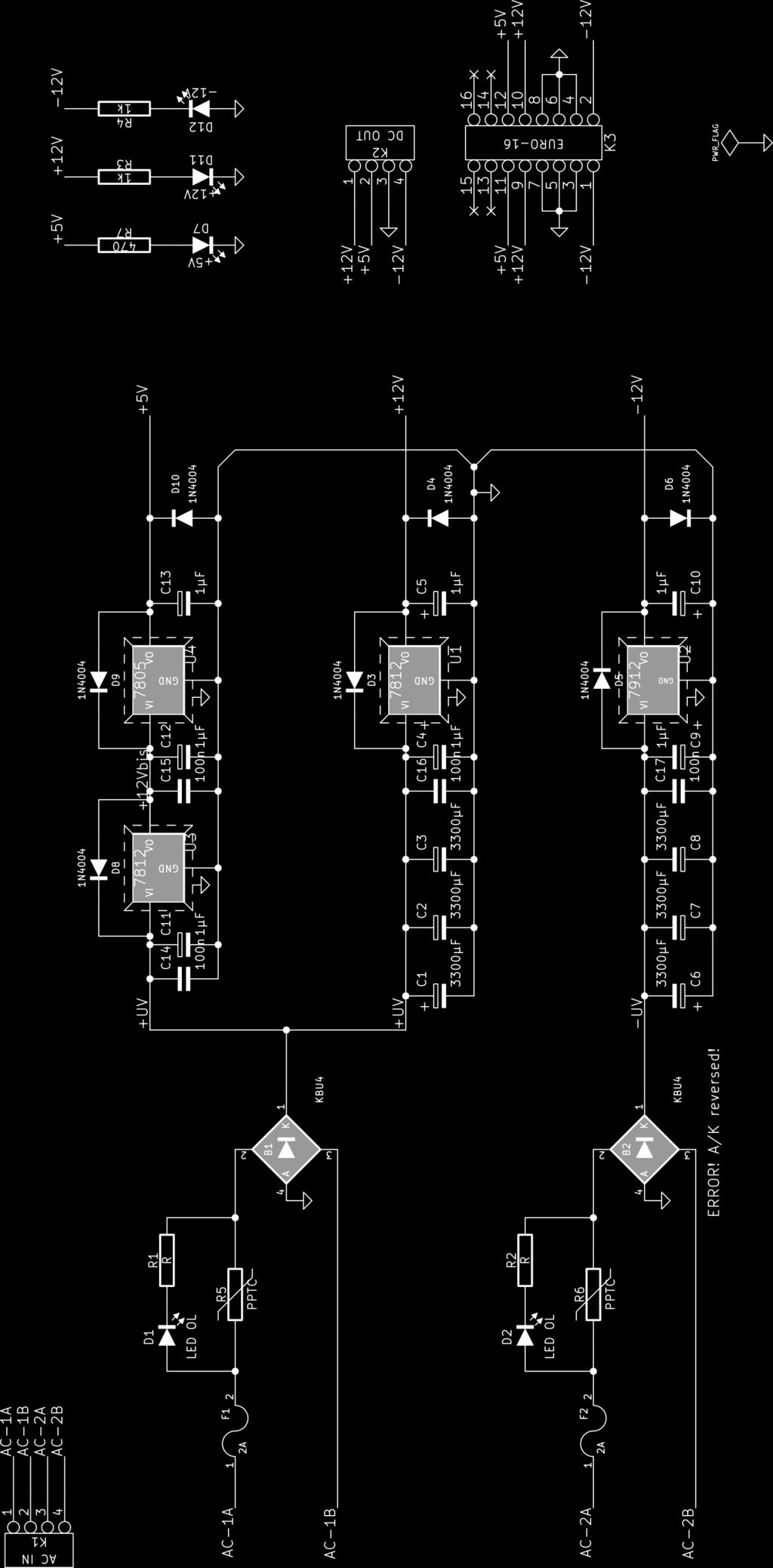
1 Eurorack 1A Power Supply Thank you for building the classic linear Eurorack 1A Power Supply. Linear power supplies are a bit old school but they still offer a very good solution for high end synthesizers. Ultra low noise (no internal oscillator involved), 100 % serviceable (no exotic component) and simple. Input: 4 wires, separate windings, screw terminal on K1. Outputs: +1V / -1V /+5V, screw terminal and Eurorack 16 pin connector. Attention Building a power supply is a serious job. High energy levels are involved. Please, refrain from building and/or using a power supply if you don't have a minimum level of knowledge in electronics. This is not a project for beginners. Risks are : high temperatures (possible burns), capacitor explosions if incorrectly positioned, and a lot of magic smoke. Not to mention, of course, dangers with mains power supply voltages when dealing with the transformer primary side. Be careful! Mains power supply voltage is highly dangerous and potentialy lethal! 1/8
2 BOM Ref Value Footprint Qty B1,B KBU4 DIOB-KBU4 C..C3, C7..C8 3300µF CAP-PRD-7.5-D18 4 C4, C5, C9..C13 1µF CAP-PRD--D5 7 C14..C17 100n CAP-RR-.54-L7-T 4 D3..D6, D8..D10 1N4004 DO-41_LP 7 D7, D11, D1 Yellow LED LED-3MM 3 F1,F A FUSE-.6-5x0-PTF78 Fuse T1,5 H1 REGUL_HEATSINK_ Special heat sinks, 94x45x30mm, X4 K / W, M3 K1, K AC IN/DC OUT SCREW-TERM K3 EURO-16 HE10_16D 1 R3,R4 1k R4_ROUND R7 470 R4_ROUND 1 U1, U3 781 LM78XXV U 791 LM79XXV 1 U LM78XXV 1 clips for heat sink 4 Heat sink mounting screws 3mmx1mm Washers 3x9mm Flat Heat sink mounting screws 3mmx10mm 3 Washers 3mm spring You will need a 1V 1A per rail, dual winding, toroidal or regular transformer. 3 /8
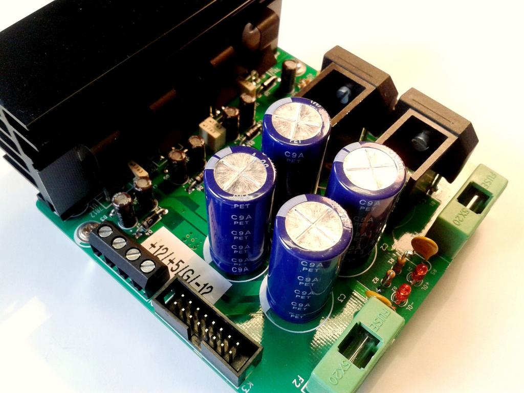
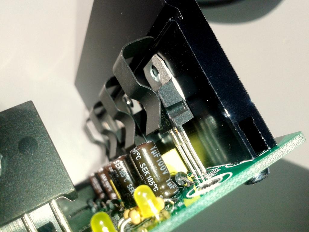
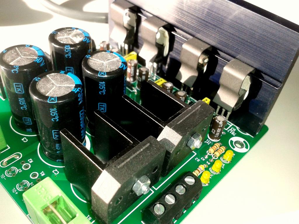
3 Errata C1, C6, R1, R, D1, D are not used and will be left unconnected. R5, R6 are not used and replaced by a strap. Use for example one cut leg from a diode. B needs to be reversed (follows the same mounting position as B1). + and marks have been reversed. Build instructions Solder small components first : resistors, diodes, leds, small capacitors. Then solder Fuse holders, medium caps, and screw terminal. Solder bigger components : mount small heatsinks on each diode bridge B1 and B. Use M3x1 screws and M3 nuts. Heatsinks need to be vertical. Place screw on heatsink side, nut on diode bridge side. Tighten well. Use thermal paste if you have some. Solder diode bridges and finally the last 4 big capacitors. Bolt the heatsink. Then place the regulators in their respective positions. DO NOT SHORT U regulator's metal part with heatsink, USE mica insulator for U. U's metal body is not connected to ground and MUST not be. Use thermal paste, if you have some, between regulator's TO0 cases, mica insulators and heatsink. Install mounting clips in order to fasten the regulators to the heatsink. Then you can solder the regulators. Do not solder regulators before they are fasten by mounting clips. Be careful, clips are hard to remove. You don't need to cut regulator's legs. If they are protuding too much from the PCB's bottom side, then regulators are incorrectly positionned. Mounting clips are in contact with the regulator's plastic cases, not the metal part. Mount the board with 4 «hex standoffs» (spacers) 10 mm length minimum, 3 mm diameter. 3/8


4 Tests Before you power on your board, double check every component. Visually inspect for incorrect values, reversed components, bad solder joints (gray, dry, cold ). Check for any possible short. Use a multimeter : check for shorts, especially between big capacitors pins, input and output connectors. Check for a possible short circuit between U case and ground. Use of a lab power bench is strongly recommended : power one side of your board with your lab power supply, current limited around 100 ma and check for voltages and over current consumption. At 14 V input, you should get correct output voltages. LED from the corresponding powered side should illuminate. If not, check output voltage and LED position. If no output voltage, check regulators position, values, and check for defective fuse. Once first side is tested ok, check the other side, use lab power supply on the second side and check second rail. Use a dual winding transformer only. Connect each winding on K1 terminals, one per rail. 4/8
5 5/8

6 6/8
7 7/8

8 Revision notes : in errata section, incorrect reference C, C6 is correct. 8/8
PSL2 Assembly guide. PSL2 Assembly guide. Resistors. Test pins. Document revision 1.1 Last modification : 30/05/08
 Safety warning THIS KIT IS NOT FOR BEGINNERS! This kit is main powered and use potentially lethal voltages. Under no circumstance should someone undertake the realisation of this kit unless he has full
FiveFish Studios PSU-2448Plus+ Assembly Guide
 FiveFish Studios PSU-2448Plus+ Assembly Guide Copyright 2015-2017 FiveFish Audio Revision 1.02-20171105 No part of this document may be reproduced, either mechanically or electronically, posted online
POWER SUPPLY MODEL XP-800. TWO AC VARIABLE VOLTAGES; 0-120V and 7A, PLUS UP TO 10A. Instruction Manual. Elenco Electronics, Inc.
 POWER SUPPLY MODEL XP-800 TWO AC VARIABLE VOLTAGES; 0-120V and 0-40V @ 7A, PLUS 0-28VDC @ UP TO 10A Instruction Manual Elenco Electronics, Inc. Copyright 1991 Elenco Electronics, Inc. Revised 2002 REV-I
Assembly and User Guide
 Assembly and User Guide 2 Amp Adjustable Electronic Load 30V and 20 Watts Max Powered by: 9V Battery Pico Load is a convenient constant current load for testing batteries and power supplies. The digital
PITNEY BOWES FLEXIBLE INK JET TRANSPORT 36 FIT BASE: FIT-36. Parts Manual. (BOM: FIT36rev1.0) FIT-36parts_rev0 1
 FIT-36parts_rev0 1") FLEXIBLE INK JET TRANSPORT 36 FIT BASE: FIT-36 Parts Manual (BOM: FIT36rev1.0) FIT-36parts_rev0 1 VERSION HISTORY The table below summarizes the history of this document as it is published onto the company
FLEXIBLE INK JET TRANSPORT 36 FIT BASE: FIT-36 Parts Manual (BOM: FIT36rev1.0) FIT-36parts_rev0 1 VERSION HISTORY The table below summarizes the history of this document as it is published onto the company
LED PICTURE FRAME KIT
 ESSENTIAL INFORMATION BUILD INSTRUCTIONS CHECKING YOUR PCB & FAULT-FINDING MECHANICAL DETAILS HOW THE KIT WORKS MAKE A DISPLAY OF YOUR MOST TREASURED PHOTOGRAPH WITH THIS LED PICTURE FRAME KIT Version
Maintenance Manual 13 AMPERE POWER SUPPLY 19A704647P1-P3. Mobile Communications LBI-31801C
 C Mobile Communications 13 AMPERE POWER SUPPLY 19A704647P1-P3 CAUTION THESE SERVICING INSTRUCTIONS ARE FOR USE BY QUALI- FIED PERSONNEL ONLY. TO AVOID ELECTRIC SHOCK DO NOT PERFORM ANY SERVICING OTHER
Introduction. Exploded View. Conveyor System - Troubleshooting Guide LAST UPDATED: 09/19/2018
 LAST UPDATED: 09/19/2018 Introduction 1. 2. 3. 4. Conveyor Drive Motor Power Cord Conveyor Drive Shaft /Sprockets 5. Belt 6. Belt Tensioning Screws Exploded View 1. 2. 3. 4. 5. 6. 7. 8. 9. 10. 11. 12.
PowerAmp Design. PowerAmp Design EVAL135 EVALUATION KIT FOR MODELS PAD135/ PAD183. Rev D
 PowerAmp Design EVALUATION KIT FOR MODELS PAD35/ PAD83 EVAL35 Rev D INTRODUCTION The EVAL35 evaluation kit provides a convenient method to become familiar with the operation of the PAD35 or PAD83 Compact
WIRING THE HEATER POWER SUPPLY
 WIRING THE HEATER POWER SUPPLY Fig. 14 13/14 Take the longer PS board (with the 47R resistors and the fuse) and, using M3x6 screws, fix it to the chassis to the left of the mains transformer. The diodes
TIMER PROJECT KIT ESSENTIAL INFORMATION. Version 2.0 TIME SOMETHING WITH THIS
 ESSENTIAL INFORMATION BUILD INSTRUCTIONS CHECKING YOUR PCB & FAULT-FINDING MECHANICAL DETAILS HOW THE KIT WORKS TIME SOMETHING WITH THIS TIMER PROJECT KIT Version 2.0 Build Instructions Before you start,
Yaskawa Electric America Unit Troubleshooting Manual Section One: Introduction & Checks Without Power GPD 506/P5 and GPD 515/G5 (0.
 Yaskawa Electric America Unit Troubleshooting Manual Section One: Introduction & Checks Without Power GPD 506/P5 and GPD 515/G5 (0.4 ~ 160kW) Page 1 Introduction This manual is divided into three sections:
PARTS LIST FOR VIPER VIPER
 P-336 P-336 PARTS LIST FOR P-336-A P-336-A ILLUSTRATION OF SUB-ASSEMBLIES 6 3 1 5 2 4 P-336-A.1 P-336-A.1 For Codes: 10597 to 10635 Do Not use this Parts List for a machine if its code number is not listed.
Linear Stepper Driver v0.9.2 Assembly Instructions
 Linear Stepper Driver v0.9.2 Assembly Instructions Here's what's included in the kit: 1x Printed Circuit board 1x Heatsink bracket 5x 0.1uF capacitors 1x 6-pin ISP header 1x 10-pin configuration header
Powercut Spare parts list. Edition Valid for serial no. 001-xxx-xxxx, 034-xxx-xxxx
 Spare parts list Edition 20111010 Valid for serial no. 001-xxx-xxxx, 034-xxx-xxxx Ordering no. Product 0558 007 636 Powercut 1600, 400V 0558 007 637 Powercut 1600, 400V 25ft 0558 007 237 Powercut 1600,
Total solder points: 93 Difficulty level: beginner advanced 10 LED MONO VU METER K4304 ILLUSTRATED ASSEMBLY MANUAL
 Total solder points: 93 Difficulty level: beginner 1 2 3 4 5 advanced 10 LED MONO VU METER K4304 Add a visual readout to your existing or new equipment. ILLUSTRATED ASSEMBLY MANUAL H4304IP-1 Features &
Doubloon Two Bus Power Supply
 Doubloon Two Bus Power Supply Augustica w w w. a u g u s t i c a. c o m DANGER This power supply kit uses high-voltage and therefore may produce a lethal shock. Only persons who are competent at electronics
SCA-80(Q) C11 REPLACEMENT ASSEMBLY MANUAL
 C11 REPLACEMENT ASSEMBLY MANUAL") SCA-80(Q) C11 REPLACEMENT ASSEMBLY MANUAL 2014-2016 AkitikA, LLC All rights reserved Revision 1p05 July 3, 2016 Page 1 of 15 Table of Contents Table of Contents... 2 Table of Figures... 2 Section 1: About
SCA-80(Q) C11 REPLACEMENT ASSEMBLY MANUAL 2014-2016 AkitikA, LLC All rights reserved Revision 1p05 July 3, 2016 Page 1 of 15 Table of Contents Table of Contents... 2 Table of Figures... 2 Section 1: About
22K (red red orange gold) 1pcs. 33K (orange orange orange gold) 5pc. 2.7 M (green violet red gold) 2pc.
 1pcs. 33K (orange orange orange gold) 5pc. 2.7 M (green violet red gold) 2pc.") TURNING FROG Long pliers, soldering, soldering iron stand with sponge, 2 AA batteries, one 9V battery, Tin, diagonal cutting pliers Turning Frog is a robot that uses a microphone as a detector. When microphone
TURNING FROG Long pliers, soldering, soldering iron stand with sponge, 2 AA batteries, one 9V battery, Tin, diagonal cutting pliers Turning Frog is a robot that uses a microphone as a detector. When microphone
QUASAR ELECTRONICS KIT No ELECTRONIC CAR IGNITION
 QUASAR ELECTRONICS KIT No. 1058 ELECTRONIC CAR IGNITION General Description The advantages of having an electronic ignition in your car are well known. Let us mention them again: 1. Perfect burning of
TIMED NIGHT LIGHT KIT
 ESSENTIAL INFORMATION BUILD INSTRUCTIONS CHECKING YOUR PCB & FAULT-FINDING MECHANICAL DETAILS HOW THE KIT WORKS RELAX YOUR WAY TO SLEEP WITH THIS TIMED NIGHT LIGHT KIT Version 2.0 Build Instructions Before
PITNEY BOWES FLEXIBLE INK JET TRANSPORT 56 FIT BASE: FIT-56. Parts Manual. (BOM: FIT-56revA) FIT-56parts_rev0 1
 FIT-56parts_rev0 1") FLEXIBLE INK JET TRANSPORT 56 FIT BASE: FIT-56 Parts Manual (BOM: FIT-56revA) FIT-56parts_rev0 1 VERSION HISTORY The table below summarizes the history of this document as it is published onto the company
FLEXIBLE INK JET TRANSPORT 56 FIT BASE: FIT-56 Parts Manual (BOM: FIT-56revA) FIT-56parts_rev0 1 VERSION HISTORY The table below summarizes the history of this document as it is published onto the company
IV-3 VFD Shield for Arduino. Assembly Manual
 June 2014 Table of Contents 1 Overview Features Applications 3 3 3 2 Assembly Hints 4 3 PCB Overview 5 4 Circuit Diagram 6 5 Assembly Diodes and IC socket Electrolytic capacitors Ceramic capacitors 10K
Simple Eurorack Row. Kit Builder's Guide. 4mspedals.com
 Simple Eurorack Row Kit Builder's Guide 4mspedals.com ' Simple Eurorack Row This guide is for building a single-row eurorack case with a power supply. When completed, the case is ready to accept eurorack
ARDUINO WORK BENCH - PART LIST
 Nº Commercial Name ARDUINO WORK BENCH - PART LIST Qty. Price [ ] /unit 1 Storage plastic box (15L) 1 4.50 4.50 all Supplier The box (closed volume, insulated, transparent, thick wall but easy to pierce
LV2000. revision 1.5. Low Voltage Power Supply Retrofit Kit for Wells-Gardner Color XY Monitor, model 19K6100. Installation Instructions ! WARNING!
 LV2000 revision 1.5 Low Voltage Power Supply Retrofit Kit for Wells-Gardner Color XY Monitor, model 19K6100 Installation Instructions! WARNING! To successfully install this kit requires that you have good
ALARM KIT ESSENTIAL INFORMATION. Version 2.0 WHAT CAN YOU PROTECT WITH THIS
 ESSENTIAL INFORMATION BUILD INSTRUCTIONS CHECKING YOUR PCB & FAULT-FINDING MECHANICAL DETAILS HOW THE KIT WORKS WHAT CAN YOU PROTECT WITH THIS ALARM KIT Version 2.0 Build Instructions Before you start,
User s Manual Rev 1.3 GME
 User s Manual Rev 1.3 GME TEST INSTRUMENT SAFETY GUIDELINES WARNING An electrical shock of over 10 milliamps of current to pass through the heart will stop most human heartbeats. Voltage as low as 35 volts
Parts. WindyNation s 40 to 120 AMP Diversion Charge Controller Wiring Diagram (copyright 2009) 40 AMP Relay. Enclosure Charge Controller
 40 AMP Relay. Enclosure Charge Controller") WindyNation s 40 to 120 AMP Diversion Charge Controller Wiring Diagram (copyright 2009) Parts 1 AMP fuse fuse holder Enclosure Charge Controller fuse fuse holder Female spade connectors Terminal connectors
WindyNation s 40 to 120 AMP Diversion Charge Controller Wiring Diagram (copyright 2009) Parts 1 AMP fuse fuse holder Enclosure Charge Controller fuse fuse holder Female spade connectors Terminal connectors
INTRODUCTION... 2 ABOUT THE VALHALLA... 2 ABOUT THIS MANUAL... 2 RETAILER & DISTRIBUTOR OBLIGATIONS... 2 HOW TO USE THIS MANUAL...
 Valhalla Service Manual Valhalla power supply for LP12 Turntable IMPORTANT DO NOT FAULT FIND ON THE VALHALLA WHILE IT IS POWERED UP unless you have read the Important Safety Information section below.
Arlo Power Distribution Board Kit Rev B (#28996)
") Web Site: www.parallax.com Forums: forums.parallax.com Sales: sales@parallax.com Technical: support@parallax.com Office: (916) 624-8333 Fax: (916) 624-8003 Sales: (888) 512-1024 Tech Support: (888) 997-8267
Web Site: www.parallax.com Forums: forums.parallax.com Sales: sales@parallax.com Technical: support@parallax.com Office: (916) 624-8333 Fax: (916) 624-8003 Sales: (888) 512-1024 Tech Support: (888) 997-8267
Maxi and Mini DC-DC Converter Evaluation Board
 BRICK FAMILY USER GUIDE Maxi and Mini DC-DC Converter Evaluation Board Features...1 Introduction...2 Set Up + OUT, OUT...3 + S, S...3 Secondary Control (SC)...3 Primary Control (PC)...4 Parallel (PR)...4
Plasma Generator Kit. Images Scientific Instruments Inc.
 Images Scientific Instruments Inc. PG13 Plasma Generator Kit This kit generates high voltage using a fly back transformer. The Plasma generator kit can be used for many high voltage experiments. Images
Bill of Materials: Car Battery/charging system diagnostics PART NO
 Car Battery/charging system diagnostics PART NO. 2192106 You can hook up the kit's test leads directly to the car battery (with engine off) and see whether battery voltage is ok (green LED on) or low (yellow
Mig 4004i, 5004i, Origo Mig 4004i. Spare parts list. Edition Valid for serial no. 145-xxx-xxxx, 211-xxx-xxxx
 Spare parts list Edition 20120828 par-01 Valid for serial no. 145-xxx-xxxx, 211-xxx-xxxx Ordering no. Product 0465 154 880 Mig 4004i 0465 155 880 Mig 5004i 0465 152 880 Origo TM Mig 4004i, with A44 control
Arlo Power Distribution Board Kit Rev B (#28996)
") Web Site: www.parallax.com Forums: forums.parallax.com Sales: sales@parallax.com Technical: support@parallax.com Office: (916) 624-8333 Fax: (916) 624-8003 Sales: (888) 512-1024 Tech Support: (888) 997-8267
Web Site: www.parallax.com Forums: forums.parallax.com Sales: sales@parallax.com Technical: support@parallax.com Office: (916) 624-8333 Fax: (916) 624-8003 Sales: (888) 512-1024 Tech Support: (888) 997-8267
Professional Wireless Products
 Page 1 of 6 093115 Communications Power Supply and Battery Management Controller Page 2 of 6 1.0 Introduction The 093115 is a 13.8 volt 15amp transformer isolated switch mode down converter designed to
Chapter 2. Battery Charger and Base Assembly
 Chapter 2 Battery Charger and Base Assembly 11 CHAPTER 2. BATTERY CHARGER AND BASE ASSEMBLY 2.1 Section Overview This Lab teaches students how to assemble a Tekbot, in the following steps: Describe the
BLUE LIGHT FOR DYNACO STEREO 120, SCA-80, OR PAT-4 ROCKER SWITCHES
 BLUE LIGHT FOR DYNACO STEREO 120, SCA-80, OR PAT-4 ROCKER SWITCHES 2014 AkitikA, LLC All rights reserved Revision 1p5 April 8, 2014 Page 1 of 16 Table of Contents Table of Contents... 2 Table of Figures...
Application Note: Assembling the DHT Coleman Regulator for Transmitting DHTs: 2.5A to 3.6A. Please Read this Note together with Andht01 [PDF Manual]
![Application Note: Assembling the DHT Coleman Regulator for Transmitting DHTs: 2.5A to 3.6A. Please Read this Note together with Andht01 [PDF Manual]](/thumbs/94/120539265.jpg "Application Note: Assembling the DHT Coleman Regulator for Transmitting DHTs: 2.5A to 3.6A. Please Read this Note together with Andht01 [PDF Manual]") Application Note: Assembling the DHT Coleman Regulator for Transmitting DHTs: 2.5A to 3.6A. Please Read this Note together with Andht01 [PDF Manual] 1. Parts you will need (NOT supplied in the kit): Lyrima,
Application Note: Assembling the DHT Coleman Regulator for Transmitting DHTs: 2.5A to 3.6A. Please Read this Note together with Andht01 [PDF Manual] 1. Parts you will need (NOT supplied in the kit): Lyrima,
THERMOMETER PROJECT KIT
 ESSENTIAL INFORMATION BUILD INSTRUCTIONS CHECKING YOUR PCB & FAULT-FINDING MECHANICAL DETAILS HOW THE KIT WORKS MEASURE INDOOR AND OUTDOOR TEMPERATURES WITH THIS THERMOMETER PROJECT KIT Version 2.0 Build
mb808 FAB manual
 mb808 FAB manual http://www.eight-oh-eight.org Step one: Power Supply: ATTENTION: You will be dealing with AC mains voltages in this part of the build, if you are not careful you can injure yourself, or
P/N: , Rev-E, 14/07/2016 Modified on 07/ V/60Hz
 P/N: 557360023-00, Rev-E, 14/07/2016 Modified on 07/16 1 110V/60Hz 2 21 22 53 35 19 12 52 31 15 51 45 18 60 57 5 46 26 11 48 7 66 36 14 28 29 30 65 41 46 58 47 40 37 33 32 8 23 3 SL.NO PART NO DESCRIPTION
PAT-4 TOROIDAL TRANSFORMER ASSEMBLY MANUAL
 PAT-4 TOROIDAL TRANSFORMER ASSEMBLY MANUAL 2015 AkitikA, LLC All rights reserved Revision 1p3 August 22, 2015 Page 1 of 13 Table of Contents Table of Contents... 2 Table of Figures... 2 Section 1: About
Build Instructions and User Guide
 Build Instructions and User Guide Getting Started To build the Rock Drill 4069 you will need: Solder Wire Cutters Soldering Iron Small pliers The kit is suitable for beginners or more experienced builders
Mfg. No: ProMax 3500 Continental
 Parts Manual Mfg. No: 030280-0 ProMax 3500 Continental Copyright Briggs and Stratton. All Rights reserved 18-Aug-2017 Model Components Table Of Contents Page Alternator & Outlet Panel..............................................................................
Silvertel. Ag Features. 2. Description. IEEE802.3bt PD Module
 Silvertel V1.1 August 2018 Datasheet 1. Features Type 4 PD Compliant with IEEE802.3bt (Draft V3.2) 85 Watt Output Power Compact DIL package - 70mm(L) x 35mm(W) x 17mm(H) High efficiency DC/DC converter
455 khz ( ) Connect the lead from the banded end of the
 Connect the lead from the banded end of the") 455 khz ( ) Connect the lead from the banded end of the Varicap diode (#56-49) to lug 1 (NS) and the other lead to lug 2 (NS) of oscillator coil L3. Refer to Pictorial 10 for the following steps. ( ) Connect
455 khz ( ) Connect the lead from the banded end of the Varicap diode (#56-49) to lug 1 (NS) and the other lead to lug 2 (NS) of oscillator coil L3. Refer to Pictorial 10 for the following steps. ( ) Connect
PARTS LIST FOR GX271. (Gasoline & LPG) GX271
 GX271") P-325 P-325 PARTS LIST FOR (Gasoline & LPG) P-325-A P-325-A ILLUSTRATION OF SUB-ASSEMBLIES 7 6 2 4 6 5 7 1 3 1 P-325-A.1 P-325-A.1 Gasoline & LPG For Codes: 10527 to 10579 Do Not use this Parts List for
P-325 P-325 PARTS LIST FOR (Gasoline & LPG) P-325-A P-325-A ILLUSTRATION OF SUB-ASSEMBLIES 7 6 2 4 6 5 7 1 3 1 P-325-A.1 P-325-A.1 Gasoline & LPG For Codes: 10527 to 10579 Do Not use this Parts List for
RE-PR3-E-86&105 3-Phase Panel Mount 86 and 105kW
 Page 1 of 6 3-Phase Panel Mount 86 and 105kW Features: Benefits: 0-10Vdc, 0-5Vdc, 4-20mA or manual via potentiometer control input Over temperature protection with auto reset Enclosed panel mounting Efficient
SMART LAB PUTTING TOGETHER THE
 PUTTING TOGETHER THE SMART LAB INSTALLING THE SPRINGS The cardboard workbench with all the holes punched in it will form the base to the many cool circuits that you will build. The first step in transforming
Total solder points: 126 Difficulty level: beginner advanced POWER DIMMER 230V) K8038 ILLUSTRATED ASSEMBLY MANUAL
 K8038 ILLUSTRATED ASSEMBLY MANUAL") Total solder points: 126 Difficulty level: beginner 1 2 3 4 5 advanced POWER DIMMER (1KW @ 230V) K8038 NOISE SUPPRESSED ACCORDING TO EN55015 Class microcontroller high power dimmer with non volatile memory
Total solder points: 126 Difficulty level: beginner 1 2 3 4 5 advanced POWER DIMMER (1KW @ 230V) K8038 NOISE SUPPRESSED ACCORDING TO EN55015 Class microcontroller high power dimmer with non volatile memory
BRIVIS DUCTED INVERTER SERVICE MANUAL DRCi
 BRIVIS DUCTED INVERTER SERVICE MANUAL DRCi 1 TABLE OF CONTENTS TABLE OF CONTENTS... 2 IMPORTANT NOTE... 3 FAULT FINDING AND DIAGNOSTICS... 3 ABBREVIATIONS... 3 PCB S... 4 OUTDOOR MAIN PCB... 4 INDOOR PCB...
Specification. Li-polymer Rechargeable Battery
 Specification of Li-polymer Rechargeable Battery Model No.: LP-573442-1S-3 Reported by: 陈声宇 Date: Dec,13,2010 Checked by: 侯刚琪 Date: Dec,13,2010 Approved by: 陈军 Date: Dec,14,2010 1. Scope This specification
The DIY Smart Saw Desktop Version - Troubleshooting and Appendices
 1 Page Contents Troubleshooting:... 3 Appendices:... 13 DIY Desktop CNC Machine Master Bill of Materials:... 13 DIY Desktop CNC Machine Stepper Driver Module Bill of Materials:... 17 DIY Desktop CNC Machine
How to Convert the IBM VAC Power Supply to 230 VAC
 How to Convert the IBM 5150 120 VAC Power Supply to 230 VAC Discussion The 120VAC version of the 5150's power supply, as-designed, is not switch or jumper-configurable for 230VAC operation. However, there
All inclusive. #MAGICPOWERMODULES
 All inclusive. #MAGICPOWERMODULES MagI³C Power s are easy to use DC/DC converters with integrated regulator IC, power inductor and capacitors. Design and layout reviews as well as support with EMI fi lter
DCX2496 Linear Power Supply mod by
 DCX2496 Linear Power Supply mod by Construction Guide Linear Power Supply for the DCX2496 Introduction. One of my more rewarding modifications to the DCX2496 was the replacement of the stock I/O board
Ljunggren Audio Roll Your Own Penta
 Ljunggren Audio Roll Your Own Penta Version: Penta 1.0 Bills Of Material Bold = PCB1, The rest = PCB2 Type Parts Des cription Pow er header Qty Value 1 2x5pin POWER Euro pow er connector Jack 1 3.5mm J1,
Installation Instructions. PowerFlex 700 Drive - Frame 8 Components Replacement
 Installation Instructions PowerFlex 700 Drive - Frame 8 Components Replacement Important User Information Solid-state equipment has operational characteristics differing from those of electromechanical
100W SUBWOOFER KIT. Total solder points: 383 Difficulty level: beginner advanced K8077 ILLUSTRATED ASSEMBLY MANUAL
 100W SUBWOOFER KIT Powerful bass from a small cabinet thanks to the dual speaker principle Total solder points: 383 Difficulty level: beginner 1 2 3 4 5 advanced K8077 ILLUSTRATED ASSEMBLY MANUAL H8077IP-1
Norcal Power/SWR Meter Assembly & Operating Manual. Revision 1D 10/15/2008
 Norcal Power/SWR Meter Assembly & Operating Manual Revision 1D 10/15/2008 Copyright 2008 NorCal QRP Club Page 1 of 21 Contents CONTENTS...2 INTRODUCTION...3 SPECIFICATIONS...3 ASSEMBLY...4 OPERATING GUIDE...15
General Overview Assembly Notes Page 1 Tech Note 1
 Page 1 Introduction It is most important for both the success and enjoyment of your building experience that you take the time to make a few preparations. Workspace You will need a clean well lighted workspace.
BLUE LIGHT FOR DYNACO STEREO 120 OR PAT-4 ROCKER SWITCHES
 BLUE LIGHT FOR DYNACO STEREO 120 OR PAT-4 ROCKER SWITCHES 2012 AkitikA, LLC All rights reserved Revision 1p3 April 18, 2012 Page 1 of 15 Table of Contents Table of Contents... 2 Table of Figures... 2 Section
Trouble Shooting 1 The power light doesn't illuminate and the scooter doesn't run The power light is on and the scooter doesn't run.
 Trouble Shooting 1.The power light doesn't illuminate and the scooter doesn't run 1) The output voltage is less than 35 V ± 1.0 V Use the multimeter to test the batteries for the voltage, if the voltage
Small Type High-Speed Response POL DC-DC Converter BSV-nano Series
 is a small (xxmm), light, 4A output step-down DC-DC converter with low output voltage from 08V and an accuracy of ±% typ It can support the latest DSP, ASIC applications High efficiency and high-speed
99 Washington Street Melrose, MA Fax TestEquipmentDepot.com. Instruction Manual. Model 1672 Triple Output Power Supply
 99 Washington Street Melrose, MA 02176 Fax 781-665-0780 TestEquipmentDepot.com Instruction Manual Model 1672 Triple Output Power Supply Contents Section Description Page No. CONTENTS 1 1 TEST INSTRUMENT
SHORT-STOP. Electronic Motor Brake Type G. Instructions and Setup Manual
 Electronic Motor Brake Type G Instructions and Setup Manual Table of Contents Table of Contents Electronic Motor Brake Type G... 1 1. INTRODUCTION... 2 2. DESCRIPTION AND APPLICATIONS... 2 3. SAFETY NOTES...
Energysaver 559FT. Rinnai New Zealand Limited Page 1 of 6 Rinnai Energysaver 559FT Spare Parts: 01-11
 039 017 028 012 019 037 020 018 038 026 701 013 038 027 804 012 Top panel 1 5485 013 Control panel assembly 1 5486 016 Side panel RH 1 5488 017 Side panel LH 1 5489 018 Air filter assembly 1 3026 019 Front
INSTRUCTION MANUAL FOR THE THERMOCOUPLE ATTACHMENT UNIT (TAU)
") INSTRUCTION MANUAL FOR THE THERMOCOUPLE ATTACHMENT UNIT (TAU) Model Number: 41756 (100 125Vac) 41757 (220 240Vac) Manufactured in the United Kingdom CONTENTS Chapter Page Specification 3 What the TAU does
INSTRUCTION MANUAL FOR THE THERMOCOUPLE ATTACHMENT UNIT (TAU) Model Number: 41756 (100 125Vac) 41757 (220 240Vac) Manufactured in the United Kingdom CONTENTS Chapter Page Specification 3 What the TAU does
3.5 Amp Bi-polar stepper motor drive MSE570 Evo 2
 3.5 Amp Bi-polar stepper motor drive MSE57 Evo 2 Features Bi-polar drive with pre-set drive currents up to 3.5 Amps per phase Increased operating voltage up to 48 V ½ step drive option for improved damping
PPS20 COMMUNICATIONS POWER SUPPLY AND BATTERY MANAGEMENT SYSTEM
 PPS20 COMMUNICATIONS POWER SUPPLY AND BATTERY MANAGEMENT SYSTEM 2 Table of Contents Introduction:... 3 1.0: Operation Principles:... 3 1.1: Stand alone supply... 3 1.2: Backed up supply:... 3 1.3: Battery
Maglev Plus System. 1. Description
 1. Description Maglev Plus System The Maglev Plus System is specifically designed to levitate various objects attached to a very strong disc magnet. It can levitate up to 25 g additional mass. The vertical
ALTERNATOR - HITACHI
 ALTERNATOR - HITACHI 1986 Isuzu Trooper II 1986 Alternators & Regulators HITACHI ALTERNATORS Isuzu DESCRIPTION Hitachi alternators are conventional 3-phase, self-rectifying alternators. Three positive
Modifications to the TS-930 Power Supply. Ken Grant, VE3FIT
 Modifications to the TS-930 Power Supply Ken Grant, VE3FIT My TS-930 has a serial number in the 5 million and uses a +21.7 Volt low-current regulator as well as the normal +28.5 V high current supply.
MAX16840L Evaluation Kit Evaluates: MAX16840
 19-5978; Rev 0; 7/11 MAX16840L Evaluation Kit General Description The MAX16840L low-power (5W input) evaluation kit (EV kit) demonstrates the MAX16840 HBLED driver IC used for Solid State Lighting (SSL)
TN1250 Technical note
 Technical note Press-fit ACEPACK power modules mounting instructions Introduction ST introduces the ACEPACK Power Module family, designed for easy mounting and reliable performance in rugged applications.
Euro Power Supply Unit (Euro PSU) Project Builder's Guide
 Project Builder's Guide") Oakley Sound Systems Euro Power Supply Unit (Euro PSU) PCB Issue 1 Project Builder's Guide V1.2 Tony Allgood Oakley Sound Systems CARLISLE United Kingdom 1 Introduction This is the Project Builder's Guide
Oakley Sound Systems Euro Power Supply Unit (Euro PSU) PCB Issue 1 Project Builder's Guide V1.2 Tony Allgood Oakley Sound Systems CARLISLE United Kingdom 1 Introduction This is the Project Builder's Guide
D6, D7, D8, D9, D12, D13, D14, D15, D16, D17, D18, D19. Schottky rectifier diode. 1N5817-1N5819 or SB130
 Roll Your Own ljunggrenaudio.com Altered States version 1.0 Bills Of Material Qty Value 12 1N4148 2 1N5818 4 1N750 4.7V 4 220p Device Diode Diode Zener diode Capacitor 30 100n 4 15p 8 560p 1 5x2 pin Capacitor
INSTRUCTION MANUAL Model 1743B
 Test Equipment Depot - 800.517.8431-99 Washington Street Melrose, MA 02176 TestEquipmentDepot.com INSTRUCTION MANUAL Model 1743B 0-35 V, 0-6 A DC POWER SUPPLY With Dual 4-Digit LED Displays TEST INSTRUMENT
Electronic Service Manuals
 Electronic Service Manuals This electronic document is provided as a service to our customers. We do not create the contents of the information contained in this document. Should you have detailed questions
SERGE Dual Universal Slope Generator (DSG) mk2 for Eurorack
 mk2 for Eurorack") SERGE Dual Universal Slope Generator (DSG) mk2 for Eurorack The Serge Dual Universal Slope Generator DSG is one of the most versatile modules in the Serge system. The DSG mk2 by Random*Source is a licensed
SERGE Dual Universal Slope Generator (DSG) mk2 for Eurorack The Serge Dual Universal Slope Generator DSG is one of the most versatile modules in the Serge system. The DSG mk2 by Random*Source is a licensed
www MK-Electronic de EPSON LQ2170 Spares Guide Version 3 Page 1
 REF PART NO DESCRIPTION REMARKS QTY 100 1025018 HOUSING ASSY., LOWER 1 101 1025039 COVER, FRONT 1 102 1025041 HOUSING, UPPER 1 103 1025027 COVER, PRINTER, REAR 1 104 1025024 COVER ASSY., PRINTER 1 105
ROBOT SOUND REVERSING CAR KIT C-9802
 ROBOT SOUND REVERSING CAR KIT TOOLS you'll need Alimentation 2 batteries 1,5 V AA (not included) You will find fun to learn electronics and mechanics assembling robot by reversing sound. This is a simple
Trouble Shooting. 1 The power light doesn't illuminate and the scooter doesn't run. 1 The output voltage is less than 35 V ± 1.0 V
 Trouble Shooting 1 The power light doesn't illuminate and the scooter doesn't run 1 The output voltage is less than 35 V ± 1.0 V Use the multimeter to test the batteries for the voltage, if the voltage
elabtronics Voltage Switch
 elabtronics Voltage Switch Want to trigger a device when a monitored voltage, temperature or light intensity reaches a certain value? The elabtronics Voltage Switch is an incredibly easy way of doing it.
LINK: See the original work on the SB-200 conversion - in complete detail - HERE
 http://ac0c.com/main/page_homebrew_sb200_tank_mods.html SB-200 Sleeper Tank Mods SB 200 mods rebuild AC0C_com A Quick Overhaul to the SB-200 Tank Circuit LINK: See the original work on the SB-200 conversion
PARTS CATALOG PROHEAT X30
 PARTS CATALOG PROHEAT X0 Rev. A TABLE OF CONTENTS A. SAFETY... A- B. SELECTION GUIDE... B- BURNERHEAD ASSEMBLY... COMPRESSOR... FUEL PUMP... FAN END AND BLOWER... FAN END ELECTRICAL... 5 HEAT EXCHANGER
IM /2017 REV01 POWER WAVE S700 CE
 POWER WAVE S700 CE IM2061 09/2017 REV01 Spare Parts... 1 POWER WAVE S700 CE... 1 Miscellaneous Items... 1 POWER WAVE S700 CE Assemblies overview... 2 Figure 1: Case Front Assembly... 3 Figure 2: Lower
PowerFlex 700 Drive - Frame 9 Components Replacement
 Installation Instructions PowerFlex 700 Drive - Frame 9 Components Replacement Catalog Numbers XXX XXX XXXX XXX XXX XXX Important User Information Solid-state equipment has operational characteristics
PM-200 POWER SUPPLY MODULE v3.2 ASSEMBLY & INSTALLATION INSTRUCTIONS
 PM-200 POWER SUPPLY MODULE v3.2 ASSEMBLY & INSTALLATION INSTRUCTIONS WARNING: Voltages inside the amplifier CAN & WILL KILL YOU! You MUST know how to work around HIGH VOLTAGE safely. If you do not, get
Training & Didactic Systems. Fundamentals of Electrical Engineering
 Training & Didactic Systems Fundamentals of Electrical Engineering Catalog WA1E/01 Table of Contents Page Our Service, Our Customers and fields of technology 2 Introduction 4 Instruction modules measuring
How to bias: Vintage 16 Rev C 6/27/2012 carvinservice.com
 How to bias: Vintage 16 Rev C 6/27/2012 carvinservice.com - 1 - Only a certified technician should bias Carvin amps, this is very dangerous, you can get hurt, please be very careful when working with any
Z TECHNICAL INSTRUCTIONS
 ÍNDICE: Z40 2.0 TECHNICAL INSTRUCTIONS 1.- Error list 2.- Replace the control board 3.- Opening the machine 4.- Replace the power board 5.- Dismantling motor and gear box 6.- Assembly of gear box 7.- Pushing
BREADBOARD PLUGIN POWER SUPPLY # REV3 +5VDC
 BREADBOARD PLUGIN POWER SUPPLY # 400039 REV3 +5VDC INDEX A. Learn Power Supply Design with a hands on approach B. General Information and Features C. Assembled Picture of the Breadboard plug-in power supply
0-28 vdc stabilized power supply with current control Amp
 0-28 vdc stabilized power supply with current control 0.002-10 Amp General Description This is a high quality power supply with a continuously variable stabilised output adjustable at any value between
PROTECTGLOBAL.COM TROUBLE SHOOTER
 PROTECTGLOBAL.COM TROUBLE SHOOTER ERROR EXPLANATION POSSIBLE SOLUTION E 1 Main supply 230 V off Check power supply and fuses, transformer connections. E 2 E 3 E 4 E 5 E 6 E 7 E 8 Low fluidmessage Fire
Parts Manual. Transfer Switch. OTPCB (Spec A) 150/225/260 Amps. English Original Instructions (Issue 4)
 150/225/260 Amps. English Original Instructions (Issue 4)") Parts Manual Transfer Switch 50/225/260 Amps OTPCB (Spec A) English Original Instructions -203 962 0228 (Issue ) This catalog covers models produced under the Cummins /Onan and Cummins Power Generation
Parts Manual Transfer Switch 50/225/260 Amps OTPCB (Spec A) English Original Instructions -203 962 0228 (Issue ) This catalog covers models produced under the Cummins /Onan and Cummins Power Generation
MOD 102 GUITAR AMP KIT (K-MOD102)
") MOD 0 GUITAR AMP KIT (K-MOD0) ON BASS TREBLE VOLUME MOD 0 TUBE AMP KIT 0 0 0 0 0 0 OFF Use these instructions to learn: How to build a tube amp. This tube guitar amplifier circuit is based on a classic
MOD 0 GUITAR AMP KIT (K-MOD0) ON BASS TREBLE VOLUME MOD 0 TUBE AMP KIT 0 0 0 0 0 0 OFF Use these instructions to learn: How to build a tube amp. This tube guitar amplifier circuit is based on a classic
White Light CLASSIC PEDAL KIT. Assembly Instructions WHEN YOU CAN T BUY IT BUILD IT. StewMac RARE / VINTAGE / HARD TO GET
 Sheet #i-2206 Updated 5/18 StewMac White Light CLASSIC PEDAL KIT Kit case is unpainted IN COLLABORATION WITH EarthQuakerDevices Assembly Instructions The White Light Overdrive is based on vintage overdrives