THE T IN DETAIL
|
|
|
- Cuthbert Watson
- 5 years ago
- Views:
Transcription


1 STEP 57 THE T IN DETAIL The tank s transmission ensured that the right amount of power was transmitted to the tank s wheels to drive at a given speed. This was achieved through the use of gear ratios. The on-board transmission took the form of a singlestage lower reduction gearbox with a transmission ratio of 5.7:1, which reduced the speed of the driving wheel relative to the main shaft. It served to constantly increase the torque on the drive wheel, due to the reduction in the speed of movement on all gears. The on-board transmission comprised a pair cylindrical gearwheels, mounted in the crankcase, welded and riveted to stern and on-board sheets of the hull, and covered by a lid attached to the crankcase by bolts. Part of the crankcase that protruded from the hull was closed by an armoured hood. The on-board transmission was divided into two nodes: the driving shaft node and the driven shaft node. There were two inal drives: right and left, located symmetrically along the sides in the stern section of the tank. The left inal drive difered from the right by the presence of a drive to the speedometer; in all other respects both inal drives were identical. 1


 and push")
.")


.")

 and a screw.")
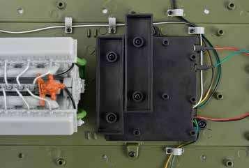
2 ASSEMBLY GUIDE 057A CODE NUMBER COMPONENT NAME QUANTITY 057A 4 LED lights with wires 1 Cable clip 7 + 1* 1.7 4mm screw 7 + 2* 2.3 4mm screw 2 + 1* VM mm screw 1 + 1* * includes spares 3Secure the whiteand-black wires with three more wire clips () in the positions shown and ix with a screw through each clip. VM 1Feed the 8-wire plug attached to the LED lights (057A) through the hole in the side of the battery box () and push it irmly on to the 8-pin connector on the printed circuit board (054A). 057A 054A 057A 2Spread out the wires so that one pair of LEDs with yellow-and-black wires and green-and-black wires go to the left side and one pair go to the right side. The white-and-black wires with the switch should go to the rear. Secure the wires with three wire clips () in the positions shown below, and ix each clip with a screw. 056A 054B 4Fit the on of switch (054B) into the rectangular hole in the rear of the lower hull (056A). Ensure that the white wire is closest to the ON marking on the underside of the hull. Fix the switch with two screws. Finally, secure the whiteand-black wires with one more wire clip () and a screw. 5Take the battery box lid (053B) supplied with issue 53 and it it over the battery box (053B), ensuring that the two support tabs engage in their corresponding slots. Fix with a VM screw. 053B VM 2 3


3 STEP 58 THE T IN DETAIL Two belt brakes were fitted in order to stop and turn the tank on the driven drums of the on-board clutches. To get the tank to turn, the belt on the corresponding on-board clutch was tightened, resulting in the caterpillar track on one side of the tank ceasing to move. But as the track on the other side of the tank continued to move, the tank turned in the direction of the braked track. The brake belt on the external drum of the on-board clutch was tightened by moving the driving levers in the direction of the stern of the tank, or by depressing the foot brake pedal. Disengagement of the on-board clutches, and tightening of the brake belts, was actuated by a drive unit that was common to the clutch and the brake. When moving the control levers in the direction of the stern of the tank, the on-board clutches were irst disengaged, after which, braking began. When the foot brake pedal was depressed, the on-board clutches were not disengaged and both external drums were braked simultaneously. The brake belt was made of sheet steel with a thickness of 2-3 mm. Thirteen cast-iron pads were riveted to the belt from the inside. 1

 on the left side of the lower hull.")
 over the lug")


.")
.")


 into one end of a brake band ().")
 into the other end of the brake band ().")
 over the rear")

 to the outside lat face of the crew")
4 ASSEMBLY GUIDE 058A 058G 058F CODE NUMBER COMPONENT NAME QUANTITY 058A Lower chassis lock 1 Brake band 2 Connector bar A 2 Connector bar B 2 058E Crew escape hatch 1 058F Hatch lock 1 3Fit the axles of one connector bar A () into the jaws of the gearbox frame (049C) on the left side of the lower hull. Then wrap the brake band () around the diferential left outer (051A). Stretch the brake band gently and it the connector bar B () over the lug projecting from the diferential left outer. EM IM UM IP 058G Hatch hinge 2 EM 2.3 5mm screw 3 + 1* IM 1.7 3mm screw 2 + 1* 049C 051A 058E UM mm screw 2 + 1* IP 1.7 3mm screw 2 + 1* * includes spares 1Fit the engine and gearbox assembly from stage 52 on to the two screw posts on the lower hull panel (055A) and on to the screw post at the rear of the lower hull (056A). Fix with three EM screws from beneath the hull. 4Repeat to it the right side brake band (). Fit the axles of the connector bar A () into the jaws of the gearbox frame (049C) on the right side of the lower hull. Then wrap the brake band around the diferential right outer (051D). Stretch the brake band gently and it the connector bar B () over the lug projecting from the diferential right outer. 051D 049C EM EM EM 056A 055A 2Carefully fit the longest axle of a connector bar A () into one end of a brake band (). You will need to bend the brake band on to the ends of the axle. Fit a connector bar B (58D) into the other end of the brake band (). Repeat for the second brake band, connector bar A and connector bar B. 058E IP IP 058G 058G 056A 058E 6Fit the lower chassis lock (058A) over the rear underside edge of the lower hull (056A) and ix with a UM screw. Do not tighten the screw fully, so that the lock can be rotated. The lock will secure the hinged transmission cover (033A) in a later stage. IM IM 058F UM 5Fit the hatch hinges (058G) to the outside lat face of the crew escape hatch (058E), ensuring that the barrel of each hinge is outermost. Fix with an IP screw through each hinge. Then it the hatch over the oval hole in the lower hull (056A) and ix with two IM screws through the hinges. Finally, it the hatch lock (058F) over the front edge of the crew escape hatch and ix with a UM screw. The hatch can now be opened by irst twisting the hatch lock. 058A UM 056A 2 3


5 STEP 59 THE T IN DETAIL The ammunition supply of the T tank consisted of 55 artillery shots for the 85-mm cannon, most of which were kept in boxes in the fighting compartment. The tank carried 55 artillery shots, 36 of which were high explosive, 14 were armour-piercing tracer projectiles, and ive sub-calibre projectiles. These were stored in the hull and turret using three diferent types of stowage: racks, clamps, and crates. The artillery shots for the gun were delivered to the crew packed in boxes. Before ammunition was placed in the tank, the condition of the packing was checked. After the shots were inspected, any grease, sand and mud on them was removed. They were sorted by their markings and weight and placed in the designated stowage area in the tank. Markings refers to conventional signs and inscriptions that were painted on the shells, shell cases and ammunition containers. 1


 to both ammunition box A (059A)")
 to ammunition box")
 to the next")

6 ASSEMBLY GUIDE 059A 059B 059C CODE NUMBER COMPONENT NAME QUANTITY 059A Ammunition box A 1 059B Ammunition box B 1 059C Small lid 2 059D Ammunition box F 1 3Fit ammunition box F (059D) to the two screw posts on the right edge of the battery box (), orientated as shown. Fix with two screws. 059E Large lid 1 059D 059E 2.3 4mm screw 6 + 2* * includes spares 1Fit ammunition box B (059B) to the two screw posts on the rear edge of the battery box (), orientated as shown. See also step 3 to ensure you it all the boxes in the correct pattern. Fix with two screws. 059D 059D 059B 059B 4Fit a small lid (059C) to both ammunition box A (059A) and ammunition box B (059B). Fix a large lid (059E) to ammunition box F (059D). No screws are required. 2Fit ammunition box A (059A) to the next pair of screw posts on the battery box (), orientated as shown. See also step 3 to ensure you it all the boxes in the correct pattern. Fix with two screws. 059C 059A 059C 059A 059E 2 3


7 STEP 60 THE T IN DETAIL In accordance with the Manual on materials and operation of the T tank the crew had to perform a number of actions when stacking artillery shots. When stacking artillery shots in a tank, it was essential to replace any KTM-1 and KTMZ-1 fuses that had a torn, punctured or broken membrane and check whether the fuse housing was damaged; if necessary it was permitted to turn it (at a distance of metres from the tank) under the direction of the artillery technician. Any kind of work with ammunition was prohibited within the tanks; it was permitted only to take of caps and remove dust and grease from artillery shots and shell cases with rags. It was ordered that: Rust was to be removed with a brass scraper and cloth impregnated with diesel fuel or kerosene; artillery shots with nicks and dents were to be replaced; The projectile was irmly attached to the shell case to the sleeve; if the projectile was loose in the case, then such a shot could not be placed into a tank or used for shooting; A cap chamber protruding from the bottom of the shell case was to be screwed in with a special key parts, and recessed more than 0.5 mm. Artillery shots that had cracks at the bottom of the shell case or on the lange, or large dents on the body, were replaced. 1


, See")

, ammunition")
. No screws are required.")
 to the front pair of")

8 ASSEMBLY GUIDE CODE NUMBER COMPONENT NAME QUANTITY 060A Ammunition box C 1 060B Ammunition box D 1 060C Ammunition box E 1 3Fit the deeper ammunition box E (060C) to the two screw posts on the lower hull panel (055A) in front of the battery box (), orientated as shown. Tuck the wires beneath the box. Fix with two screws. 060D Small lid 3 060A 060B 060C 060D 2.3 4mm screw 2 + 1* 2.3 4mm screw 4 + 1* 060C * includes spares 060C 1Fit ammunition box C (060A) to the two screw posts at the centre of the battery box (), orientated as shown. See also step 3 to ensure you it all the boxes in the correct pattern. Fix with two screws. 060A 060A 4Fit a small lid (060D) to ammunition box C (060A), ammunition box D (060B) and ammunition box E (060C). No screws are required. 060D 060D 060D 060B 2Fit ammunition box D (060B) to the front pair of screw posts on the battery box (), orientated as shown. See also step 3 to ensure you it all the boxes in the correct pattern. Fix with two screws. 060B 2 3
THE T IN DETAIL
 STEP 9 THE T-34-85 IN DETAIL The ammunition for the ZIS-S-53 gun comprises 55 artillery rounds (unitary cartridges), placed in the hull and turret of the tank in three types of storage: a rack, cable ties
THE T IN DETAIL
 STEP 17 THE T-34-85 IN DETAIL The T-34 tank, can, without exaggeration, be regarded as the world s first universal tank, and yet its creators did not have the slightest inkling that this was the case.
THE T IN DETAIL
 STEP 25 THE T-34-85 IN DETAIL T-34 tanks produced between 1940-1941 were fitted with a heavy, hinged driver s hatch which had two bases for prismatic observation devices, or triplexes, in which a glass
THE T IN DETAIL
 STEP 97 THE T-34-85 IN DETAIL One of the most important endeavours of the NII-48 s lay in the development of moulding solutions for the armour parts. The process itself of moulding armoured steel wasn
THE T IN DETAIL
 STEP 21 THE T-34-85 IN DETAIL In 1944, the T-34-856 tank was introduced as a replacement for the T-34 tank. This fighting machine was produced until 1946 at three Tank Ministry plants: No 183 in Nizhny
THE T IN DETAIL
 STEP 29 THE T-34-85 IN DETAIL One of the most important elements of the T-34 s superiority was its operational range the distance the tank could cover from one refuelling to the next. The operational range
LA County Fire Department Pre -Trip Inspection Class B Vehicles
 LA County Fire Department Pre -Trip Inspection Class B Vehicles Pre Trip Inspection This slide program was designed to assist firefighter s s with their pre trip inspection This slide program comes with
DRIVE SHAFT LOCATION INDEX
 DRIVE SHAFT LOCATION INDEX 2005 DRIVELINE/AXLE Drive Shaft - MX-5 Miata Fig. 1: Identifying Drive Shaft Location DRIVE SHAFT PRE-INSPECTION 1. Inspect the dust boot on the drive shaft for cracks, damage,
Pre-Trip Inspection Tractor Trailer
 Pre-Trip Inspection Tractor Trailer CHECK OUTSIDE IN FRONT OF YOUR VEHICLE (Front of Vehicle, Lights/Reflectors, Engine Compartment & Steering Components) 1. Clearance lights, head lights, four-way flasher
Installation Instructions
 Preparing your vehicle to install your brake system upgrade 1. Rack the vehicle. 2. If you don t have a rack, then you must take extra safety precautions. 3. Choose a firmly packed and level ground to
1992 Clutch. Eclipse, Expo/Expo LRV, Galant, Mirage, Precis, 3000GT
 Article Text ARTICLE BEGINNING 1992 Clutch Eclipse, Expo/Expo LRV, Galant, Mirage, Precis, 3000GT DESCRIPTION All clutches are single disc type. Pressure plate assembly uses a diaphragm spring to engage
THE T IN DETAIL
 STEP 37 THE T-34-85 IN DETAIL The B-2 [Kharkiv model V-2] engine consisted of a crankcase; two cylinder blocks; a crank rod mechanism; transmission; power system; lubricating, cooling and starting mechanisms.
SD Bendix ET-2 Electronic Treadle DESCRIPTION OPERATION
 SD-15-4106 Bendix ET-2 Electronic Treadle PIVOT SPRING MOUNTING BASE DESCRIPTION CONNECTOR FIGURE 1 - ET-2 ELECTRONIC TREADLE ROLLER TREADLE COVER DOUBLE RETURN SPRING CABLE ASSEMBLY The ET-2 is an electronic
PART A. INSTRUCTION SHEET FOR LOCK SERVICE PACK XW4Z CB, 5W4Z BB AND 4R3Z AA
 KIT, 5W4Z-5421991-BB AND 4R3Z-6321990-AB Item # Part Number Description Used In Package Quantity A SK 5W4A-5421991-BB Instruction Sheet (48387) All 1 B1 324341 Tumbler # 1 All 4 B2 324342 Tumbler # 2 All
Rostra Electronic Cruise Control Install On a Stratoliner or Roadliner
 Rostra Electronic Cruise Control Install On a Stratoliner or Roadliner MATERIALS LIST: 1 - Rostra Part # 250-1223 (www.brandondist.com/products/cruise1223.htm) 1 - Signal Splitter part # 250-4369 1 - Engagement
SECTION H STEERING. Section Description Page No. H.1 GENERAL DESCRIPTION 3 H.2 STEERING WHEEL 3 H.3 INNER COLUMN 5 H.
 SECTION H STEERING Section Description Page No. H.1 GENERAL DESCRIPTION 3 H.2 STEERING WHEEL 3 H.3 INNER COLUMN 5 H.4 OUTER COLUMN 5 H.5 STEERING UNIT LOCK STOPS 6 H.6 STEERING UNIT 6 H.7 STEERING ARMS
CRUISE CONTROL SYSTEM
 CRUISE CONTROL SYSTEM 1994 Volvo 960 1994 ACCESSORIES/SAFETY EQUIPMENT Cruise Control System 960 DESCRIPTION & OPERATION MAIN SWITCH Cruise control main switch is located at end of directional signal lever.
INSTALLATION INSTRUCTIONS
 INSTALLATION INSTRUCTIONS REAR DISC BRAKE CONVERSION KIT A126-1 1973-87 CHEVROLET 1/2 TON 2WD Thank you for choosing STAINLESS STEEL BRAKES CORPORATION for your braking needs. Pleases take the time to
Steeda Lower Control Arms ( )
") Steeda Lower Control Arms (2005-2012) NOTE: The following installation was performed on a 2007 Mustang GT/California Special. The control arms were previously sold in a blue color, but now they are sold
Steeda Lower Control Arms (2005-2012) NOTE: The following installation was performed on a 2007 Mustang GT/California Special. The control arms were previously sold in a blue color, but now they are sold
INSTALLATION INSTRUCTIONS 97 FORD EXPEDITION
 INSTALLATION INSTRUCTIONS 97 FORD EXPEDITION 1. Read the instructions completely and carefully before you begin. Check the kit for proper contents (refer to the part s list and the picture diagrams). Before
END WHEEL NO- TILL 706NT & 1006NT
 END WHEEL NO- TILL 706NT & 1006NT DRILL MAINTENANCE Proper servicing and adjustment is the key to the long life of any farm implement. With careful and systematic inspection of your grain drill, you can
REMOVAL & INSTALLATION
 REMOVAL & INSTALLATION FRONT DISC BRAKE PADS 1. Raise and support front of vehicle. Remove wheels. Remove caliper bolt and brakeline bracket bolts. Pivot caliper aside. Remove pads and pad shim. Remove
3 Axles and brakes. 3.1 Function and construction of the axles Construction Function
 3 Axles and brakes 3.1 Function and construction of the axles 3.1.1 Function Each wheel has an independent suspension system in the axle body (1), so that individual wheel suspension is provided. The swinging
DISC BRAKES. Section 4. Components and Operation of Disc Brakes. Disc Brake Assembly
 DISC BRAKES Components and Operation of Disc Brakes A disc brake assembly consists of a: cast iron disc (disc rotor) that rotates with the wheel. caliper assembly attached to the steering knuckle. friction
Your G3 buggy is fitted with three switches on the front part of the body:
 CONTENTS Buggy operation... 3 General Maintenance... 5 Technical Maintenance... 6 Front wheel bearing replacement... 6 Rear wheel bearing replacement... 7 Chain replacement... 8 Chain Adjustment... 9 Brake
FPU SYSTEMS OPERATION MANUAL BOH PORTABLE DRAWER MODULE (PDM) (INCLUDING REPAIR PARTS & SPECIAL TOOL LIST) BOH FPU Field Pack-up Units CHAPTER 5
 (INCLUDING REPAIR PARTS & SPECIAL TOOL LIST) BOH FPU Field Pack-up Units CHAPTER 5") FPU SYSTEMS OPERATION MANUAL BOH PORTABLE DRAWER MODULE (PDM) (INCLUDING REPAIR PARTS & SPECIAL TOOL LIST) BOH FPU Field Pack-up Units CHAPTER 5 UNIT MAINTENANCE INSTRUCTIONS 06 BOH Environmental LLC This
FPU SYSTEMS OPERATION MANUAL BOH PORTABLE DRAWER MODULE (PDM) (INCLUDING REPAIR PARTS & SPECIAL TOOL LIST) BOH FPU Field Pack-up Units CHAPTER 5 UNIT MAINTENANCE INSTRUCTIONS 06 BOH Environmental LLC This
The parking brake is an electrically actuated system that operates drum brakes integrated into the rear brake discs. The
 Page 1 of 15 Published: Oct 22, 2004 Parking Brake COMPONENT LOCATIONS Item Part Number Description 1 Clutch pedal position sensor (manual transmission models only) 2 Parking brake indicators (all except
Splicing Procedures 4. 2 Insert the new wire between the parted strands. If more than one wire is being spliced, wrap them in opposite directions. Use
 Splicing Procedures 1 Splicing Procedures Refer to applicable wiring diagrams for circuit information. This procedure contains multiple splicing techniques. Review splicing procedures prior to performing
I. Before starting installation
 5. Park the vehicle on a clean, dry, flat, level surface and block the tires so the vehicle cannot roll in either direction. A. Disconnect battery cables 1. Disconnect the negative cable first, then the
Vehicle Inspection Study Guide TRUCK/TRAILER (PINTLE HOOK)
") Department of Motor Vehicles Vehicle Inspection Study Guide TRUCK/TRAILER (PINTLE HOOK) During the actual tests, you will be expected to point to or touch each of the parts of your vehicle listed below.
Department of Motor Vehicles Vehicle Inspection Study Guide TRUCK/TRAILER (PINTLE HOOK) During the actual tests, you will be expected to point to or touch each of the parts of your vehicle listed below.
INSTALLATION INSTRUCTIONS
 INSTALLATION INSTRUCTIONS REAR DISC CONVERSION KIT A126-2 1988-98 C1500 2WD 10" REAR DRUM Thank you for choosing STAINLESS STEEL BRAKES CORPORATION for your braking needs. Pleases take the time to read
Sachs 48mm Closed Cartridge fork Service Manual
 Sachs 48mm Closed Cartridge fork Service Manual 1 Fork seal driver 2 Special soft jaws 3 Fork cap wrench 4 Rebound rod holding tool 5 Compression assembly holding tool 6 Retaining clip tool Special Tools
SM64155 Maintenance & Repair Manual
 SM64155 September 2011 Applicable addition manuals: Aerospace Group Conveyance Systems Division Carter Brand SM61429 Nozzle SM64349 Nozzle SM64201 Nozzle Maintenance & Repair Manual Continuity Dry Break
Mamod SL1K Locomotive Assembly Instructions
 Mamod SL1K Locomotive Assembly Instructions LOCOMOTIVE ASSEMBLY INSTRUCTIONS To ensure ease of construction reference to these instructions are essential. All the major parts are in the front of the box
Hawk Brake Pads ( Mustang GT/V6 Rear Pair)
") Hawk Brake Pads (1994-2004 Mustang GT/V6 Rear Pair) The below installation instructions work for the following products: Hawk HPS Brake Pads (1994-2004 Mustang GT/V6 Rear Pair) Hawk Performance Ceramic
Hawk Brake Pads (1994-2004 Mustang GT/V6 Rear Pair) The below installation instructions work for the following products: Hawk HPS Brake Pads (1994-2004 Mustang GT/V6 Rear Pair) Hawk Performance Ceramic
The EFL 2000/1 & 2 User Guide Test Sieve Shaker. Contents
 The EFL 2000/1 & 2 User Guide Test Sieve Shaker ISSUE 04-02 Contents Description Page 1 Setting Up: 2-8 Unpacking 2 Assembly 3 Clamping Assembly 4 Electrical Connections 5 Sieve Stacking 6 8 Operating
UNPACK AND IDENTIFY THE FOLLOWING PARTS.
 SUT-350-AIT ASSEMBLY REQUIREMENTS *Torque all T-bolt nuts to 35-40 foot pounds. *Check all lights before towing. *Tire pressure not to exceed recommendation on serial tag. *Re-torque wheel nuts after first
SE 'LF-PRO PELLED LOWER BELT DRIVE SERVICING
 SE 'LF-PRO PELLED LOWER NOTE Whenever wheel height or handle height is changed, clutch control rod and lever must be readjusted. Loosen clamp, lock drive unit in outof-drive position. Pull up clutch controlever
This file is available for free download at
 This file is available for free download at http://www.iluvmyrx7.com This file is fully text-searchable select Edit and Find and type in what you re looking for. This file is intended more for online viewing
INSTALLATION INSTRUCTIONS DODGE DAKOTA 2 KIT # 682 (2WD), 692 (4WD) 3 KIT # 683 (2WD), 693 (4WD)
, 692 (4WD) 3 KIT # 683 (2WD), 693 (4WD)") INSTALLATION INSTRUCTIONS 1997-1999 DODGE DAKOTA 2 KIT # 682 (2WD), 692 (4WD) 3 KIT # 683 (2WD), 693 (4WD) Installation of a Performance Accessories body lift kit will change the vehicle s center of gravity
INSTALLATION INSTRUCTIONS 1997-1999 DODGE DAKOTA 2 KIT # 682 (2WD), 692 (4WD) 3 KIT # 683 (2WD), 693 (4WD) Installation of a Performance Accessories body lift kit will change the vehicle s center of gravity
INSTALLATION & OWNER S MANUAL
 p. 1 of 15 INSTALLATION & OWNER S MANUAL Polaris Ranger 500-800 PathPro SS Cab (fits 2010 - current) (p/n: 1POLRFS1) The contents of this envelope are the property of the owner. Be sure to leave with the
A SUCCESSFUL EUROPEAN COOPERATION POWERFUL & COMPACT 40 CTAS CASED TELESCOPED ARMAMENT SYSTEM
 A SUCCESSFUL EUROPEAN COOPERATION POWERFUL & COMPACT 40 CTAS CASED TELESCOPED ARMAMENT SYSTEM A SUCCESSFUL EUROPEAN COOPERATION COMPANY CTA International is a 50/50 Joint Venture Company founded in 1994
SUT-450-I ASSEMBLY REQUIREMENTS
 SUT-450-I Torque wrench, carpenters square, wire cutters, Phillips screwdriver, 7/16, 9/16, and 3/4 combination wrenches, ratchet, 9/16,3/4,13/16, and 7/8 sockets. ASSEMBLY REQUIREMENTS *Torque all T-bolt
INSTALLATION INSTRUCTIONS
 INSTALLATION INSTRUCTIONS FRONT DISC BRAKE CONVERSION KITS A148-9 & A148-15 1949-54 Chevy Trucks Thank you for choosing STAINLESS STEEL BRAKES CORPORATION for your braking needs. Please take the time to
Depress each tab as you pull the bezel off. The bezels are tight. L.H. shown.
 2013-2014 Ford Mustang V6 & Boss 302 Lower Valance Fog Light Kit Parts List: Quantity: Tool List: Fog light & bulb with bracket 2 Flat head & Phillips screwdriver Black bezels 2 Ratchet & Socket set OR
The 6-Speed Manual Gearbox 08D
 Service. Self-Study Programme 299 The 6-Speed Manual Gearbox 08D Design and Function The Touareg is an exclusive cross country vehicle with the driving properties and driving comfort of a sporty luxury
INSTALLATION & OWNER S MANUAL
 Rev. C p. 1 of 21 INSTALLATION & OWNER S MANUAL F5205 HARD SIDED CAB KIT INSTALLATION & OWNER S MANUAL The contents of this envelope are the property of the owner. Be sure to leave with the owner when
Build your own THUNDERBIRD 2
 PACK 11 PAGE 67 Pod 4 ramp tracks and Jet Air Transporter 224 68 Left rear booster and Alan s Racing Car 227 69 Right rear booster and Alan s Racing Car 230 70 Left booster speaker 233 71 Right rear booster
Changes in direction.! Using pulleys with belts
 Mechanisms Changes in direction! Using pulleys with belts Changes in direction! Using friction wheels Changes in direction! Using gears Worm drive! Reduces the speed! It is non-reversible Worm drive! Multiple
GftOUP 4 PARKING BHAKE
 PARKING BRAKE 4-1 GftOUP 4 PARKING BHAKE CONTENTS Page Data and Specifications... 1 External Contracting Type Parking Brake...... 2 Parking Brake Band Lining 3 Parking Brake Internal Expanding Type 5 Parking
INSTALLATION INSTRUCTIONS
 INSTALLATION INSTRUCTIONS REAR DISC BRAKE CONVERSION KIT A158 1994-97 Dodge Ram 1500 (2WD & 4WD) and REAR DISC BRAKE CONVERSION KIT A158-1 1998-01 Dodge Ram 1500 (2WD & 4WD) Thank you for choosing STAINLESS
Module 6: Air Foundation Brakes
 Air Brakes Terms and Definitions Basic Components That Make Up Air Foundation Brakes Types of Air Foundation Brakes Parts of a Cam Foundation Brake Parts of a Wedge Foundation Brake Parts of a Disc Foundation
Edition Manual Chapter Page Workshop Manual, Stiga Park 4 Hydraulic system 8
 2008-05-19 Workshop Manual, Stiga Park 4 Hydraulic system 8 The charge pump (1) and the main pump (2) are integrated into one unit, the hydraulic pump (C) which is located separat in front of the engine.
#TL T EA888 GEN 3 FUELING SYSTEM/ INSTALLATION INSTRUCTIONS
 #TL100069 2.0T EA888 GEN 3 FUELING SYSTEM/ INSTALLATION INSTRUCTIONS Notes: These instructions were written for a North American specification MkVII GTI. Other models, like the Golf R, are similar. When
Trinity Low Profile Vehicle Restraint System
 Trinity Low Profile Vehicle Restraint System Through Track Mandrel (TTM) Pre-Trip, Installation, Removal, and Field Repair Manual Revision 1 July 15, 2015 Trinity Parts & Components, LLC 2525 N. Stemmons
USER S MANUAL CAUTION. Visit our website at. new products, prizes, fitness tips, and much more!
 Patent Pending Model No. 831.159730 Serial No. The serial number is found in the location shown below. Write the serial number in the space above. USER S MANUAL Serial Number Decal SEARS, ROEBUCK AND CO.
SD Bendix E-10PR Retarder Control Brake Valve DESCRIPTION. OPERATION - Refer to Figure 2
 SD-03-832 Bendix E-10PR Retarder Control Brake Valve MOUNTING PLATE SUPPLY 4 PORTS ELECTRICAL AUXILIARY DESCRIPTION TREADLE RETARDER CONTROL SECTION EXHAUST DELIVERY 4 PORTS FIGURE 1 - E-10PR RETARDER
CLUTCH SECTION CL CONTENTS C TRANSMISSION/TRANSAXLE CL-1
 CLUTCH C TRANSMISSION/TRANSAXLE SECTION CL A B CLUTCH CL D CONTENTS E PRECAUTIONS... 2 Caution... 2 PREPARATION... 3 Special Service Tools... 3 Commercial Service Tools... 3 NOISE, VIBRATION AND HARSHNESS
SECTION ZF FRONT AXLE
 04-101.01/ 1 2011JA14 SECTION 04-101.01 6 3 5 1 2 9 1. Upper radius rod 2. Lower radius rod 3. Caliper 4. BRAKE Disk 5. Pneumatic connector 6. Hub 7. steering knuckle 8. Grease Fitting 9. Pneumatic connector
TRUCKINGTRUTH.COM T T. Daniel B s Pre-Trip Inspection Checklist
 TRUCKINGTRUTH.COM T T Daniel B s Pre-Trip Inspection Checklist 1 My pre-trip begins as I approach the vehicle. I am looking for leaks, leaning one way or the other (which may indicate a low tire or bad
Installation Manual TWM Performance Short Shifter 2008 Mitsubishi Lancer
 Page 1 Installation Manual TWM Performance Short Shifter 2008 Mitsubishi Lancer Please Note: It is preferable to park on a flat surface, as you will have to engage and disengage the hand brake and shift
Group 4 CONTENTS DATA AND SPECIFICATIONS
 PARKING BRAKE 1 Group 4 PARKING BRAKE CONTENTS Paragraph Page Parking Brake 5 4 Disassembly Assembly Adjustment Parking Brake Cable 6 5 Removal Installation Service Diagnosis 1 2 DATA AND SPECIFICATIONS
Clutch Kit Install Guide
 Jack up and support the car on jack stands Remove the exhaust system (some models) Remove the driveshaft (rear wheel drive) Remove CV axle (front wheel drive) Manual transmission removal Clutch Kit Install
HEATED HAND GRIP KIT
 -J0596 REV. 00-- HEATED HAND GRIP KIT GENERAL Kit Number 56000 Models For model fitment information, see the P&A Retail Catalog or the Parts and Accessories section of www.harley-davidson.com (English
1989 Jeep Cherokee. STEERING COLUMN' '1989 STEERING Jeep Steering Columns STEERING COLUMN STEERING Jeep Steering Columns
 STEERING COLUMN 1989 STEERING Jeep Steering Columns DESCRIPTION All models use collapsible steering columns. All columns have integral ignition switch and locking device. Optional tilt wheel is available
STEERING SYSTEM - MANUAL RACK & PINION
 STEERING SYSTEM - MANUAL RACK & PINION 1993 Nissan Sentra 1993 STEERING Nissan Manual Rack & Pinion NX, Sentra DESCRIPTION & OPERATION Steering gear assembly is a manual rack and pinion type. Unit is mounted
CIRRUS AIRPLANE MAINTENANCE MANUAL
 MODEL SR PASSENGER AND CREW DOORS. DESCRIPTION AND OPERATION Serials 000 thru 00: The two crew/passenger doors incorporate a flush-mount outside door handle, key-operated door lock, and a conventional
GPS AutoSteer System Installation Manual
 GPS AutoSteer System Installation Manual John Deere MFWD AutoTrac Ready Supported Models 8225R 8245R 8270R 8295R 8320R 8345R PN: 602-0254-01-A LEGAL DISCLAIMER Note: Read and follow ALL instructions in
Brake Upgrade Kit Fitting Instructions Bonneville America
 WARNING: Always have Triumph approved parts, accessories and conversions fitted by a trained technician of an authorised Triumph Dealer. The fitment of parts, accessories and conversions by a technician
BORG WARNER TRANSFER BOX
 BORG WARNER TRANSFER BOX Overhaul Manual BORG WARNER 44-62 TRANSFER BOX OVERHAUL MANUAL This transfer box is used on the following models: New Range Rover Published by Rover Technical Communication 1996
Key Installation Points. Table of Contents
 Installation Guide Key Installation Points Table of Contents All pipe sizes in this guide are internal diameter (DN) We recommend PE-X pipe NOT copper pipe Check pipes sizes For domestic installations
INSTRUCTION MANUAL INSTALLING NEW GREASE IN UT SERIES PNEUMATIC ACTUATOR
 INSTRUCTION MANUAL INSTALLING NEW GREASE IN UT SERIES PNEUMATIC ACTUATOR This instruction manual explains the steps required to degrease and install new grease into the Max-Air UT series pneumatic actuator.
Safety, Operation and Maintenance Instructions For Long & Short Nose Upholstery Air Stapler (NS10 & NS11)
") Safety, Operation and Maintenance Instructions For Long & Short Nose Upholstery Air Stapler (NS10 & NS11) Important: Drop 3 drops of oil into the stapler air inlet BEFORE first use. See page 2. Please
Safety, Operation and Maintenance Instructions For Long & Short Nose Upholstery Air Stapler (NS10 & NS11) Important: Drop 3 drops of oil into the stapler air inlet BEFORE first use. See page 2. Please
Fitting Instructions: Rocket III / Classic / Roadster A and A Heated Grips Kit
 A96804 and A96805 - Heated Grips Kit Always have Triumph approved parts, accessories and conversions fitted by a trained technician of an authorised Triumph Dealer. The fitment of parts, accessories and
w w w. h d o n l i n e s h o p. d e CHROME SWITCH HOUSING KIT GENERAL HANDLEBAR SWITCH REMOVAL/INSTALLATION FXDWGI AND FXDBI MODEL TURN SIGNAL REMOVAL
 -J00 REV. 00-07-9 GENERAL Kit Number 70-9B, 70-9B, 708-9C Models For the most up-to-date model fitment information, please see the product label or www.harley-davidson.com. See Table for items contained
Single-Sided Storage Rack Assembly Instructions
 Single-Sided Storage Rack Assembly Instructions H D I G J K M L F I D B C A E PART NAME QTY A. BASE BAR (50 ) 2 B. BASE BAR HULL GUARD (34 ) 2 C. BASE BAR END CAP 2 D. SAFETY END CAP 4 E. FOOT 4 F. UPRIGHT
SIDEWALK PLAY CAR 174 POPULAR MECHANICS
 SIDEWALK PLAY CAR L By Elmer V. Clark IVELY youngsters and craftsman fathers alike will get a thrill out of this tiny play car, which looks and drives like a real automobile except that it's scaled down
Pre-Trip Inspection Bus, School Bus.
 Pre-Trip Inspection Bus, School Bus. CHECK OUTSIDE IN FRONT OF YOUR VEHICLE (Front of Vehicle, Lights/Reflectors, Engine Compartment & Steering Components) 1. Clearance lights, alternately flashing amber
Dodge Cummins Positive Air Shutoff
 1 INSTALL MANUAL 2010-2012 6.7 Dodge Cummins Positive Air Shutoff P/N# 1036722 P/N# 1036722-M UPLEASE READ ALL INSTRUCTIONS BEFORE INSTALLATION An Information decal has been provided in this kit. This
Hypertech Inline Speedometer Calibrator Module Installation Instructions PN Chevrolet Silverado
 Hypertech Inline Speedometer Calibrator Module Installation Instructions PN 730124-2017 Chevrolet Silverado This installation manual shows an example installation on a 2017 Chevrolet 1500. The installation
Transmission Overhaul Procedures-Bench Service
 How to Assemble the Lower Reverse Idler Gear Assembly Special Instructions In 1996 Eaton changed the reverse idler system design. In the nut design, the reverse idler bearing was lubricated through a hole
INSTALLATION INSTRUCTIONS
 INSTALLATION INSTRUCTIONS REAR DISC CONVERSION KIT A136-1 1976-86 AMC 20 AXLES WITH WARN FULL FLOATING AXLE CONVERSION Thank you for choosing STAINLESS STEEL BRAKES CORPORATION for your braking needs.
By AM Customer: Dean Smith, Aug. 8, 2014.
 Ford Racing Bullitt Axle-Back Exhaust (05-09 GT, GT500) By AM Customer: Dean Smith, Aug. 8, 2014. Tools for the Job: 13mm Wrench 13mm Socket 15mm Socket 15mm Deep Socket Ratchet(s) [I used a bigger one
XK8 / XKR Navigation to Triple Gauge Cluster Conversion Harness Kit. Instructions
 XK8 / XKR Navigation to Triple Gauge Cluster Conversion Harness Kit Instructions Kit Contents: 1 - Gauge Cluster Wiring Harness 1 - Posi-Tap connector 4-4" Tie-Wraps 1- Cable pulling tool (shipped pre-applied
HEAVY DUTY TROLLEY JACK. Operation Manual
 HEAVY DUTY TROLLEY JACK 4T Operation Manual Make sure to read and fully understand the instruction manual before using this product and keep the manual properly 1 General Description Product Description
INSTALLATION INSTRUCTIONS
 INSTALLATION INSTRUCTIONS INSTALLATION INSTRUCTIONS FOR A136 REAR DRUM TO DISC BRAKE CONVERSION KIT for 1970-75 Jeep, CJ SERIES with Dana 44 flanged axle Thank you for choosing STAINLESS STEEL BRAKES CORPORATION
Quick Start Guide Compact 24 LET ( s/n & up)
") Quick Start Guide Compact 24 LET (920022 s/n 000101 & up) Step 1: Assemble Handlebar Step 2: Install Trigger Cable Assembly Step 3: Install Discharge Chute Step 4: Install Discharge Chute Crank Step 5:
Quick Start Guide Compact 24 LET (920022 s/n 000101 & up) Step 1: Assemble Handlebar Step 2: Install Trigger Cable Assembly Step 3: Install Discharge Chute Step 4: Install Discharge Chute Crank Step 5:
DEFENDER SERIES. 5 Gallon, Double Walled, Field Replaceable Spill Container Model Series INSTALLATION, OPERATION, & MAINTENANCE
 DEFENDER SERIES 5 Gallon, Double Walled, Field Replaceable Spill Container Model 705-550 Series INSTALLATION, OPERATION, & MAINTENANCE Franklin Fueling Systems 3760 Marsh Rd. Madison, WI 53718 USA Tel:
INSTALLATION INSTRUCTIONS
 INSTALLATION INSTRUCTIONS REAR DRUM TO DISC BRAKE CONVERSION KIT A118 pre-1985 Ford F150 (except 1983-1984 w/super H/D axle) Thank you for choosing STAINLESS STEEL BRAKES CORPORATION for your braking needs.
Armor How-To KITBASHING DRAGON S T-34/85M
 Armor How-To KITBASHING DRAGON S T-34/85M 58 FineScale Modeler December 2002 1/35 Scale Story and photos by Peter Rasmussen A scratchbuilt turret turns a T-34 into a modern-era tank killer Combining ICM
Installation Operation Maintenance. LSSN Butterfly Valve AGA Approved 50MM - 150MM. QAD#IM6055.REVA
 LSSN Butterfly Valve Installation Operation Maintenance Licence Number: 5326 www.challengervalves.com.au 1 Index 1. INTRODUCTION 1.1 Design Features 3 1.2 Flange and Pipe Compatibility 4 1.3 Operating
REPAIR AND MAINTENANCE MANUAL
 REPAIR AND MAINTENANCE MANUAL Index Section I Suggested Tool Kit Page 2 Section II List of Commonly Replaced Parts Page 3 Section III Cables Page 4-7 Section IV Cable Handles Page 8 10 Section V Casters
ILLUSTRATION ILLUSTRATION
 ILLUSTRATION ILLUSTRATION REMOVAL 1. DISABLE BRAKE CONTROL (a) Wait at least 2 minutes after the power switch off. When the brake pedal is depressed or the door courtesy switch is turned on even if the
CLUTCH - HIGH EFFORT - DASH CRACKED IN CLUTCH MASTER CYLINDER AREA-VEHICLES BUILT BEFORE 6/15/90
 Page 1 of 17 HIGH CLUTCH EFFORT/CLUTCH FLUID LEAK - CRACKED MOUNT TECHNICAL SERVICE BULLETIN Reference Number(s): 90-16-7, Date of Issue: August 1, 1990 Related Ref Number(s): 90-16-7 ARTICLE BEGINNING
Gentex by VOXX Corporation Installation Instructions
 KIT CONTENTS: Item Qty Part Number Description 1 1: ADVGEN20A 7 Pin Auto-Dimming Mirror with Compass and Temperature 2 1 Gentex by VOXX Corporation Installation Instructions Contact VOXX Customer Service
Supplement to Spare Parts Catalogue. Model : FT Dual Transmission - F
 Supplement to Spare Parts Catalogue Model : FT - 60 Dual Transmission - F10001760 CONTENTS Tab. No. Sheet No. DESCRIPTION Page No. 1 101764-8 HEAD LIGHT, REAR LIGHT AND PLOUGH 1 LAMP 2 101766A-7 SHEET
Steering Column. Steering Column Component Layout.
 Page 1 of 9 Published : May 5, 2004 Steering Column Steering Column Component Layout Item Part Number Description 1 - Screw (3 off) 2 - Steering angle sensor 3 - Upper steering column assembly 4 - Cowl
INSTRUCTION MANUAL ELECTRIC DIESEL PUMP KIT
 AFP12-im -issue2-2017 INSTRUCTION MANUAL ELECTRIC DIESEL PUMP KIT INSTRUCTION MANUAL ELECTRIC DIESEL PUMP KIT INTRODUCTION Thank you for purchasing a Macnaught 12 or 24 volt Electric Diesel Fuel Pump.
Re-Energy.ca - Solar Electricity - Build Your Own Solar Car
 Backgrounder Build Your Own Solar Car Back to Page 1 Build It! These step-by-step instructions provide you with a plan for making a basic solar car. If you can think of ways to improve the design of your
uaz work price-list Mortar Investments a.s. UAZ-469 repair price-list Page 1
 Mortar Investments a.s. UAZ-469 repair price-list Item pcs work/unit tot.work per hour work price parts all spares total vehicle as it is 1 0 0 0 0 A. Drive train. 1. engine engine take out if body taken