THE T IN DETAIL
|
|
|
- Jeffry Mathews
- 5 years ago
- Views:
Transcription


1 STEP 25 THE T IN DETAIL T-34 tanks produced between were fitted with a heavy, hinged driver s hatch which had two bases for prismatic observation devices, or triplexes, in which a glass prism was fitted in the periscope. The base for the devices was itted in the upper section of the hatch. Seals itted into grooves welded to the inside rim, plus plates welded to the external cover, were supposed to prevent gun shot entering the tank. From 1942, a hatch of a simpliied shape with two prismatic observation devices was introduced, while the hatch s thickness was increased from 45 to 75 mm. The cover was locked by means of two latches attached inner side. A self-locking handle was itted to the central section of the cover, whose housing was welded to the inner side. The cover had two vertical windows for the prismatic observation devices for the driver. The prisms were protected on the outside from bullets and shrapnel by two folding armoured covers that resembled eyelids. The hatch had two windows for the prismatic observation devices, protected from the outside by hinged armoured covers (seen here closed). 1


 2 4Clip")
 firmly into the hinge bases on the")


 in the")


 with the")


 so that it covers the")
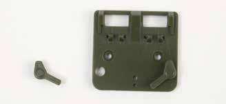
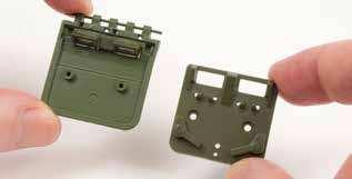
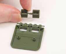
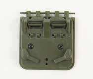
2 ASSEMBLY GUIDE Driver s hatch 1 025B Driver s hatch hinge 1 025C Left periscope cover 1 025D Right periscope cover 1 025H Driver s hatch left lock handle 1 025I Driver s hatch right lock handle 1 025J Driver s hatch closing handle 1 025K Spacer (washer) 2 4Clip the hinge pins of the two persicope inner covers () firmly into the hinge bases on the driver s hatch inner face (). 025E Driver s periscopes mm screw 2+1* Driver s hatch inner face mm screw 4+1* Persicope inner cover 2 * includes spares 025B 025C 025D 025J 025H 025I 025J 025J 5Push the driver s hatch closing handle (025J) into the two holes in the driver s hatch inner face () in the position shown. 1Fit the driver s hatch left hook handle (025H) and right hook handle (025I) to the driver s hatch inner face () in the positions shown. Fix each handle from behind with an screw. 025E 025E 025H 025E 025K 025I 2Push the driver s periscopes (025E) into the two rectangular apertures in the driver s hatch (). Ensure that the two ridges between the periscopes fit over the single off-set ridge between the two holes the persicopes will therefore only fit correctly one way round. 025C 025D 7Fit the driver s hatch assembly over the central aperture in the front of the upper hull () and engage the two screw posts in the underside of the hinge (025B) with the holes above the aperture. Turn the upper hull upside-down and place the two spacers (washers) (025K) over the protruding screw posts, then fix with two screws. 025B 025B 6Clip the hinge pins of the left periscope cover (025C) into the hinge base on the driver s hatch () so that it covers the left periscope. Repeat for the right periscope cover (025D). Then clip the driver s hatch hinge (025B) over the other side of the hinge base. 025K 3Fit the driver s hatch inner face () over the driver s hatch (), ensuring that the screw posts engage with each other inside and that the persicopes protrude through the two rectangular apertures. Fix with two screws. 8This is how the driver s hatch looks when it is fitted. NOTE: With the lock handles (025H and 025I) unfastened on the inside, the hatch can be lifted up and down. 2 3

3 STEP 26 THE T IN DETAIL It was in enhancing the means of attack, not defense, that improved the performance of the T It was not the thickening of the turret s armour plating that made the T more formidable, but the installation in it of a powerful new gun. With a 76-mm gun, the iring distance could be increased, with a corresponding decrease in the probability of the tank being struck by enemy shells. Of major importance was the provision in the turret of space for a third crew member, which relieved the commander of the need to function as the gunner, enabling him to concentrate fully on observing the battleield, searching for targets and most importantly, leading the his crew members with maximum efectiveness. As a result, eicient pre-emptive and retaliatory ire and the efectiveness of anti-artillery manoeuvres were considerably enhanced. Improved sights and a radio set also helped. The presence, in particular, of a radio allowed not only quick responses to command orders, but also enabled the commander to be notiied of changes in the situation on the battleield. The T tank was equipped with three MK-4 periscopic rotating sights. The gunner s sight and the loader s sight were located in the turret roof, while the commander s sight was placed in the hatch cover of the commander s cupola. 1


 on the right front of the")


 into the two small holes in")


4 ASSEMBLY GUIDE 026C Hull side reinforcement 2 026B Hull front reinforcement 1 026C Hull U-fork 2 026D Hull opening hook 2 3Fit the hull front reinforcement (026B) into the two recessed holes on the front of the upper hull () beside the turret ring base. Fix from beneath the upper hull with two screws. 026B 1.7 4mm screw 6 + 2* 026B 026D * includes spares 026B 1Fit one of the hull side reinforcements () into the two recessed holes on the left side of the upper hull () beside the turret ring base. Fix from beneath the upper hull with two screws. 026C 026C 4Push one of the hull U-forks (026C) firmly into the small hole in the left front of the upper hull (). There is a lug on the lower side of the engaging pin to ensure the U-fork fits the correct way up. Repeat for the second hull U-fork (026C) on the right front of the upper hull. 2Fit the second hull side reinforcement () into the two recessed holes on the right side of the upper hull () beside the turret ring base. Fix from beneath the upper hull with two screws. 5Push the two hull opening forks (026D) into the two small holes in the left side of the upper hull (), centrally beneath the left radiator air intake grille (017C). Orientate the hooks as shown. 017C 026C 026D 026D 026D 2 3


5 STEP 27 THE T IN DETAIL The poor quality and location of the T-34 s sight devices was considered a major shortcoming as early as 1940; by 1941 improvements were under way. In 1940, the 360 sight device was installed to the rear of the tank commander s position in the turret hatch cover on the right. Looking through the device was diicult, while viewing was possible in a limited sector: it ofered a view along the horizon to the right, up to 120, with a blind spot of 15m. The restricted ield of view, as well as the extremely awkward position one needed to adopt when viewing, made this sight device completely unit for its purpose. By the autumn of 1941 it had been removed, and only the PT-4-7 sight could be used for 360 viewing (which allowed viewing only within a very narrow sector of 26 ). The sight devices at the sides of the turrets were inconveniently located, too, and in the cramped turret one would have needed to be able to twist oneself around in order to make use of them. Moreover, up to 1942 these devices, and also those for the driver, were itted with mirrors of polished steel, which gave a very low image quality. In 1942 SLR sight devices in the T-34 were replaced by prismatic ones, while in the «improved» turret there were already vision slits with triplex glass blocks. 1


, ensuring that the")

 to the lower half of the")


 over the lower")


6 ASSEMBLY GUIDE 027A 027A External fuel tank 1 upper half 1 027B External fuel tank 1 lower half 1 027C Cradle mm screw 6 + 2* 3Fit the assembled fuel tank to the two sockets at the rear left of the upper hull (), ensuring that the filler cap and handle are at the top. Fix with two screws from inside the upper hull. * includes spares 027B 027C 1Fit the cradle (027C) to the lower half of the external fuel tank 1 (027B), ensuring that the two screw posts fit into the recesses in the lower horizontal channel. Fix from inside with two screws. 027B 027C 2Fit the upper half of the external fuel tank 1 (027A) over the lower half (027B), ensuring that the filler cap is at the top, closest to the cradle handle. Fix with two screws through the back. 027B 027A 4This is how the upper hull looks when the external fuel tank 1 has been fitted. 2 3


7 STEP 28 THE T IN DETAIL Until mid-1943, the quantity and quality of sight devices on the T-34 was poor, which created serious difficulties for all crew members. Two mirrored sight devices were located on the T-34 s front hull plate, while a central mirrored periscope was itted in the upper section of the hatch cover. Since the beginning of 1942 the T-34 was itted with a driver s hatch of a simpler shape with two prismatic vision devices. For protection against bullets and shrapnel, the prisms were closed on the outside with folding armoured covers. The quality of the prisms, made of yellow-green organic glass, was dreadful. Trying to see anything through them especially in a moving, shaking tank was virtually impossible. For this reason, the driver often opened his hatch slightly, which enabled him to ind his bearings by the terrain. In addition, the driver s sight devices quickly became clogged with dirt and dust. Armoured covers, or eyelids, slowed the process: while the tank was moving, one eyelid was closed and the driver was able to observe through the other ; when that became clogged with dirt, the irst one was opened. Insufficient sight devices, their poor location and low quality lead to the loss of visual contact among the tanks and premature detection by the enemy. 1


,")

")


8 ASSEMBLY GUIDE 028B 028C 028D 028A HM IP 028A Hull nose piece 1 028B Towing hook 2 028C Peg 1 028D Opening hook 2 HM 2.0 4mm screw 2 + 1* IP 1.7 3mm screw 3 + 1* * includes spares 3Fit the peg (028C) through the loops of both towing hooks (028B). Then fit the base of the peg into the socket behind the front left mudguard in the upper hull (), ensuring that the notch engages. Fix with an IP screw from beneath the hull. IP 1Fit the hull nose piece (028A) to the front of the upper hull () and fix with two HM screws through the two tabs into the posts on the underside of the hull. 028B 028C HM 028A HM 028A 2Fit the opening hooks (028D) to the raised fixing holes at the front of the upper hull (), ensuring that the notch engages and that the larger part of the hook it uppermost. Fix each hook with an IP screw from beneath the hull. 4This is how the front of the upper hull looks when this stage is complete. 028D IP IP 028D 2 3
THE T IN DETAIL
 STEP 29 THE T-34-85 IN DETAIL One of the most important elements of the T-34 s superiority was its operational range the distance the tank could cover from one refuelling to the next. The operational range
THE T IN DETAIL
 STEP 17 THE T-34-85 IN DETAIL The T-34 tank, can, without exaggeration, be regarded as the world s first universal tank, and yet its creators did not have the slightest inkling that this was the case.
THE T IN DETAIL
 STEP 9 THE T-34-85 IN DETAIL The ammunition for the ZIS-S-53 gun comprises 55 artillery rounds (unitary cartridges), placed in the hull and turret of the tank in three types of storage: a rack, cable ties
THE T IN DETAIL
 STEP 21 THE T-34-85 IN DETAIL In 1944, the T-34-856 tank was introduced as a replacement for the T-34 tank. This fighting machine was produced until 1946 at three Tank Ministry plants: No 183 in Nizhny
THE T IN DETAIL
 STEP 57 THE T-34-85 IN DETAIL The tank s transmission ensured that the right amount of power was transmitted to the tank s wheels to drive at a given speed. This was achieved through the use of gear ratios.
mit Simmering Sla.16 Pz.Kpfw. VI Ausf. B (H) Deutschland, 1945 Henschel-Werke German Heavy Tank * «Steel Generals» - series of paper
 Deutschland, 1945 Henschel-Werke German Heavy Tank * «Steel Generals» - series of paper") models of armored vehicles War Thunder «Steel Generals» - series of paper German Heavy Tank Pz.Kpfw. VI Ausf. B (H) mit Simmering Sla.6 Henschel-Werke Deutschland, 945 0 German Heavy Tank King Tiger In
models of armored vehicles War Thunder «Steel Generals» - series of paper German Heavy Tank Pz.Kpfw. VI Ausf. B (H) mit Simmering Sla.6 Henschel-Werke Deutschland, 945 0 German Heavy Tank King Tiger In
THE T IN DETAIL
 STEP 97 THE T-34-85 IN DETAIL One of the most important endeavours of the NII-48 s lay in the development of moulding solutions for the armour parts. The process itself of moulding armoured steel wasn
Premium Dry Freight (Plywood) Door Installation REFERENCE FIGURE 1
 Door Installation REFERENCE FIGURE 1") Premium Dry Freight (Plywood) Door Installation A Premium door can be identified as usually having a two-spring balancer, 2 diameter (nominal) rollers, and end hinges with removable covers. If your Whiting
Premium Dry Freight (Plywood) Door Installation A Premium door can be identified as usually having a two-spring balancer, 2 diameter (nominal) rollers, and end hinges with removable covers. If your Whiting
Nissan Titan / / Front Bumper Installation Instructions. Removal. Hardware. 12mm/1.
 2004-2014 Nissan Titan 20-915-04 / 22-915-04 / 24-915-04 Front Bumper Installation Instructions Hardware 6 ½ Hex Bolts 10 ½ Lock Washers 16 ½ Flat washers 6 ½ Hex Nuts 4 12mm/1.25 x 35mm Removal 1. First,
INSTALLATION INSTRUCTIONS 97 FORD EXPEDITION
 INSTALLATION INSTRUCTIONS 97 FORD EXPEDITION 1. Read the instructions completely and carefully before you begin. Check the kit for proper contents (refer to the part s list and the picture diagrams). Before
Landships of Mogdonazia by John Bell
 Landships of Mogdonazia by John Bell These rules are made to interact with Larry Brom s The Sword and The Flame rules set. Anything not explained here might be found in TSATF. It should be noted that the
Loose Parts Note: Determine the left and right sides of the machine from the normal operating position.
 Brake Kit Dingo TX 0 & Compact Utility Loader Part No. 0 0 & 0 Loose Parts Note: Determine the left and right sides of the machine from the normal operating position. Description Qty. Use Drive wheel Brake
Armor How-To KITBASHING DRAGON S T-34/85M
 Armor How-To KITBASHING DRAGON S T-34/85M 58 FineScale Modeler December 2002 1/35 Scale Story and photos by Peter Rasmussen A scratchbuilt turret turns a T-34 into a modern-era tank killer Combining ICM
One- Touch Installation Instructions
 One- Touch Installation Instructions 1 1 Height Adjustable Pivot w/ screws 9 Upper Work Surface 2 Rail Mount Knobs 10 Back Cover 3 Transformer 11 Center Pivot w/ screws 4 Support Legs 12 Left Monitor Arm
Build your own THUNDERBIRD 2
 PACK 03 PAGE 12 Pod 3 front hatch and Elevator Car 2 43 13 Pod 3 rear hatch and Elevator Car 2 46 14 Pod 3 floor and Elevator Car 2 49 15 Pod 3 frames and FAB 1 52 16 Pod 3 frames and FAB 1 55 17 Pod 3
SECTION H STEERING. Section Description Page No. H.1 GENERAL DESCRIPTION 3 H.2 STEERING WHEEL 3 H.3 INNER COLUMN 5 H.
 SECTION H STEERING Section Description Page No. H.1 GENERAL DESCRIPTION 3 H.2 STEERING WHEEL 3 H.3 INNER COLUMN 5 H.4 OUTER COLUMN 5 H.5 STEERING UNIT LOCK STOPS 6 H.6 STEERING UNIT 6 H.7 STEERING ARMS
Image 1. Wirbelwind based on Pz IV chassis.
 During the later years of World War II, the German air force had lost control of the air. This was particularly true on the western front. British and American planes roamed almost at will seeking ground
INSTALLATION INSTRUCTIONS
 AUTOMOTIVE PRODUCTS, INSTALLATION INSTRUCTIONS HDX DROP STEP APPLICATION: 2007-2017 Chevy Silverado / GM Sierra / 1500-2500-3500 Ext. / Double / Crew Cab PART NUMBER: 56-13715, 56-13725 ITEM QUANTITY DESCRIPTION
Installation instructions, accessories - Rear Seat Entertainment
 XC90 Section Group Weight(Kg/Pounds) Year Month 3 39 2004 10 XC90 2003, XC90 2004, XC90 2005, XC90 2006, XC90 2007, XC90 2008 Replaces issue: 2003 12 J3904620 Page 1 of 18 Required tools A0000162 A0000163
INSTALLATION INSTRUCTIONS DODGE DAKOTA 2 KIT # 682 (2WD), 692 (4WD) 3 KIT # 683 (2WD), 693 (4WD)
, 692 (4WD) 3 KIT # 683 (2WD), 693 (4WD)") INSTALLATION INSTRUCTIONS 1997-1999 DODGE DAKOTA 2 KIT # 682 (2WD), 692 (4WD) 3 KIT # 683 (2WD), 693 (4WD) Installation of a Performance Accessories body lift kit will change the vehicle s center of gravity
INSTALLATION INSTRUCTIONS 1997-1999 DODGE DAKOTA 2 KIT # 682 (2WD), 692 (4WD) 3 KIT # 683 (2WD), 693 (4WD) Installation of a Performance Accessories body lift kit will change the vehicle s center of gravity
Desktop 5.5 Z Axis Retrofit
 Page 1 Kit parts Desktop 5.5 Z Axis Retrofit Carriage plate with stop bolt and Z proximity switch installed Zip ties Spare bolts Spindle mounting plate with stop bolt, spring mount, and rail Z proximity
Polaris 9300 Series Robotic Cleaner
 Polaris 9300 Series Robotic Cleaner 9300 Sport 9300xi Sport Zodiac Pool Systems, Inc. 1-800-822-7933 www.zodiacpoolsystems.com Regional Extension Instructor ext. Sales Representatives ext. ext. Service
COMPANY COMMANDER SUPPORT WEAPONS TACTICAL BRIEFING ON SUPPORT WEAPONS
 COMPANY COMMANDER SUPPORT WEAPONS TACTICAL BRIEFING ON SUPPORT WEAPONS Although towed artillery weapons are by nature cumbersome and hard to handle, their destructive power is substantial. The quantity
C15C C15C. Page 1 of 20
 2 x Lid Front Hinge 1135 8 x M8 Bolt 8 x M8 Washer (3mm Thick) 4 x M6 Large washers 4 x M6 Spring washers 4 x M6 x 40mm Bolts 6 x M6 20mm Bolts 6 x M6 Washers 20 x Screws 2 x Lid mount gas strut bracket
Up-Armored HMMWV CASEVAC Conversion Kit (UAH-CCK)
") M1114 Up-Armored HMMWV CASEVAC Conversion Kit (UAH-CCK) Operation Performance Measures Place CCK Into Operation Task: Conditions & Standard (1) Given one UAH with CCK installed and stored. (2) Two trained
M1114 Up-Armored HMMWV CASEVAC Conversion Kit (UAH-CCK) Operation Performance Measures Place CCK Into Operation Task: Conditions & Standard (1) Given one UAH with CCK installed and stored. (2) Two trained
INSTRUCTION MANUAL ALL TERRAIN PALLET TRUCK HAND PALLET TRUCK
 INSTRUCTION MANUAL ALL TERRAIN PALLET TRUCK HAND PALLET TRUCK WARNING! 1. Read and understand instruction manual before using the pallet truck. 2. Do not place hands or feet under the pallet truck at any
Parts List DAKAR PRO Brackets Part # Chevrolet Silverado /4WD
 Installation Instructions BR5 Front Bumper Replacement Part Number 24128T Ram 1500 2/4WD (Not compatible with ParkSense, Sport, Express and Rebel Models) Parts List DAKAR PRO Brackets Part # 524765 2014
Light Source Replacement
 Lighting Electrics Electronics Thermal Management Sales Support Technical Service Our Ideas, Your Success. Light Source Replacement Ideas today for the cars of tomorrow Table of contents Audi A2 1.4 TDI.............4
The Sidewinder Wheeled Armoured Personnel Carrier.
 The Sidewinder Wheeled Armoured Personnel Carrier. The sidewinder APC is a simple wheeled vehicle I scratch built. This document will provide you with the information to duplicate it for yourself. This
TOYOTA HIGHLANDER RUNNING BOARD HIGHLANDER HV Preparation
 Preparation Part Number: PT738-48080 Kit Contents Item # Quantity Reqd. Description 1 1 Driver Side Running Board 2 1 Passenger Side Running Board 3 4 /Middle Mount Bracket 4 2 Rear Mount Bracket 5 2 Rear
and excellence Effectiviness XA-series Armoured Wheeled Vehicle Family
 XA-series Armoured Wheeled Vehicle Family Patria Vehicles Oy P.O. Box 186 FIN-13101 Hämeenlinna Finland Tel. +358 3 6451 Fax +358 3 619 6710 vehicles@patria.fi www.patria.fi From 1st January 2003: Tel.
INSTALLATION INSTRUCTIONS Dodge Ram Crew / Mega 2500/3500 2/4WD NOTE: (tow hooks will not be re-attached) PART # P5056
 PART # P5056") INSTALLATION INSTRUCTIONS 2010-14 Dodge Ram Crew / Mega 2500/3500 2/4WD NOTE: (tow hooks will not be re-attached) PART # P5056 PARTS LIST: Qty Description Qty Description 1 Grill Guard Bar 6 12mm x 30mm
INSTALLATION INSTRUCTIONS 2010-14 Dodge Ram Crew / Mega 2500/3500 2/4WD NOTE: (tow hooks will not be re-attached) PART # P5056 PARTS LIST: Qty Description Qty Description 1 Grill Guard Bar 6 12mm x 30mm
Maintenance Information
 04581245 Edition 2 May 2014 Air Grinder, Die Grinder and Sander Series G2 (Angle) Maintenance Information Save These Instructions Product Safety Information WARNING Failure to observe the following warnings,
How to remove and replace the Foonf/Fllo fabric
 How to remove and replace the Foonf/Fllo fabric Remove Headrest Locate the Troubleshooting Tool behind the manual on the back of the car seat, as shown in Figure 1. Raise Headrest to highest position by
INSTALLATION INSTRUCTIONS FORD F-150 2WD & 4WD RETAINS FACTORY TOW HOOKS PART #P3063
 INSTALLATION INSTRUCTIONS FORD F-150 2WD & 4WD RETAINS FACTORY TOW HOOKS PART #P3063 PARTS LIST: 1 Grille Guard 2 10-1.5mm Nylon Lock Nuts 1 Driver/Left Frame Mounting Bracket 4 12mm Plastic Washers 1
»Product» Safety Warning
 #J9210 Installation Instructions 2007-13 Jeep Wrangler JK 2" Body Lift Kit Read and understand all instructions and warnings prior to installation of product and operation of vehicle. Zone Offroad Products
+ + Unit is polarised indicated by the red (+VE) and black (-VE) wires.
 and black (-VE) wires.") INSTALLATION INSTRUCTIONS BRITON 996 FIG.66 ELECTRO MAGNETIC HOLD OPEN/FREE SWING DOOR CLOSER 24VDC SURFACE FIXED TO PUSH SIDE OF DOOR. 0996/093/00 Issue 01 SIZE 3 SIZE 4 SIZE 5 closer suitable for doors
INSTALLATION INSTRUCTIONS BRITON 996 FIG.66 ELECTRO MAGNETIC HOLD OPEN/FREE SWING DOOR CLOSER 24VDC SURFACE FIXED TO PUSH SIDE OF DOOR. 0996/093/00 Issue 01 SIZE 3 SIZE 4 SIZE 5 closer suitable for doors
EZ LITE CRUISER. Service & Maintenance Manual
 EZ LITE CRUISER Service & Maintenance Manual Table Of Contents Introduction to the EZ Lite Cruiser 3 Identification of Components 4 Controller System Component Diagram 6 Controller System I/O Ports Detail
Auto-Lift Operating System
 Installation Instructions Parasol Cellular Shades Auto-Lift Operating System CONTENTS Getting Started: Product View... 1 Tools and Fasteners Needed... 2 Installation: Installation Overview... 3 STEP 1
FREEDOM4. Portable Restroom Assembly Instructions
 FREEDOM4 Portable Restroom Assembly Instructions 2530 Xenium Lane North, Minneapolis, MN 55441 Telephone: 763-553-1900 Fax: 763-553-1905 800-328-3332 / www.satelliteindustries.com 9/18 REVD 22541 INSTRUCTION,
I. Before starting installation
 5. Park the vehicle on a clean, dry, flat, level surface and block the tires so the vehicle cannot roll in either direction. A. Disconnect battery cables 1. Disconnect the negative cable first, then the
Sachs 48mm Closed Cartridge fork Service Manual
 Sachs 48mm Closed Cartridge fork Service Manual 1 Fork seal driver 2 Special soft jaws 3 Fork cap wrench 4 Rebound rod holding tool 5 Compression assembly holding tool 6 Retaining clip tool Special Tools
GLACIER PRO RANGER MID SIZE MOUNT KIT
 GLACIER PRO RANGER MID SIZE MOUNT KIT P/N 2880261 APPLICATION FOR USE WITH THE GLACIER PRO MID SIZE PLOW SYSTEM (P/N 2880260) ON 2010 AND NEWER RANGER MID SIZE MODELS BEFORE YOU BEGIN Read these instructions
WARGAME RULES 20mm Scale Russo-German War c. 1943
 WARGAME RULES 20mm Scale Russo-German War c. 1943 Mike Adams December 2001 Ver 3 Based on Battle! by Charles Grant Setup The setup is determined by the scenario being played. Troops in cover may begin
INSTALLATION INSTRUCTIONS
 INSTALLATION INSTRUCTIONS WARNING: NEVER EXCEED YOUR VEHICLE MANUFACTURER'S RECOMMENDED TOWING CAPACITY PIN-STYLE TRUNNION BAR WEIGHT DISTRIBUTION KIT MAINTENANCE Keep the socket-mounted ends of the spring
USE THE PARTS LIST BELOW TO MAKE SURE YOUR KIT IS COMPLETE BEFORE INSTALLATION. IF ANY PIECES ARE MISSING, PLEASE CONTACT:
 60-65 Ford Falcon Triangulated 4-Link Suspension Installation Instructions Tech Line: 1-855-693-1259 www.totalcostinvolved.com Read and understand these instructions before starting any work! USE THE PARTS
Build your own THUNDERBIRD 2
 PACK 11 PAGE 67 Pod 4 ramp tracks and Jet Air Transporter 224 68 Left rear booster and Alan s Racing Car 227 69 Right rear booster and Alan s Racing Car 230 70 Left booster speaker 233 71 Right rear booster
INSTALLATION MANUAL Model
 VAN SOLUTIONS FOR THE WAY YOU WORK INSTALLATION MANUAL Model 2291-3-01 ATTENTION: PLEASE READ AND UNDERSTAND ALL INSTRUCTIONS AND WARNINGS BEFORE ASSEMBLING, INSTALLING OR USING THIS PRODUCT. CAUTION Be
(1) License Plate Light (2) License Plate Plugs
 License Plate Light (2) License Plate Plugs") PARTS LIST: 1 HD Replacement Bumper 4 12mm x 40mm Hex Bolts 1 Driver/Left Bracket 4 12mm Nylon Lock Nuts 1 Passenger/Right Bracket 8 12mm x 37mm x 3mm Oversize Flat Washers 2 Thin Side Spacers 4 Rubber
PARTS LIST: 1 HD Replacement Bumper 4 12mm x 40mm Hex Bolts 1 Driver/Left Bracket 4 12mm Nylon Lock Nuts 1 Passenger/Right Bracket 8 12mm x 37mm x 3mm Oversize Flat Washers 2 Thin Side Spacers 4 Rubber
INSTALLATION INSTRUCTIONS
 AUTOMOTIVE PRODUCTS, INSTALLATION INSTRUCTIONS Thrasher Board APPLICATION: 007-017 Chevy Silverado / GM Sierra / 1500-500-3500 Extended / Double / Crew Cab PART NUMBER: 8-8105, 8-81035 ITEM QUANTITY DESCRIPTION
Part C: World War I Trench Warfare
 Part C: World War I Trench Warfare Trench Warfare is a type of fighting where both sides build deep trenches as a defense against the enemy. These trenches can stretch for many miles and make it nearly
INSTALLATION GUIDE Front Bumper. KL Cherokee (Trailhawk)
") INSTALLATION GUIDE Front Bumper KL Cherokee (Trailhawk) Included Hardware: Sample Sample Sample Skill Level: 5/5 stars (Professional install recommended) Disclaimer Expedition One is not responsible for
INSTALLATION GUIDE Front Bumper KL Cherokee (Trailhawk) Included Hardware: Sample Sample Sample Skill Level: 5/5 stars (Professional install recommended) Disclaimer Expedition One is not responsible for
CORKSPORT Short Ram Intake
 I N S T A L L A T I O N I N S T R U C T I O N S CORKSPORT Short Ram Intake 2018+ Mazda 6 2.5T & 2016+ CX-9 PART #: ATK-6-117-xxxxx Need Help With Your Installation? Call (360) 260-CORK PAGE 1 CORKSPORT
Figure 3-1. MK 67 MOD 7 gun cradle.
 CHAPTER 3 GROUND AND VEHICLE MOUNTS The MK 19 is used in either the ground- or vehicle-mount mode. The most often used ground mount is the M3 tripod. The M3 serves as a stable platform when the weapon
INSTALLATION INSTRUCTIONS
 AUTOMOTIVE PRODUCTS, INSTALLATION INSTRUCTIONS R7 Step Board APPLICATION: 007-017 Chevy Silverado / GM Sierra / 1500-500-3500 Ext. / Double / Crew Cab PART NUMBER: 8-7100, 8-7105, 8-71030, 8-71035 ITEM
INSTALLATION INSTRUCTIONS
 INSTALLATION INSTRUCTIONS OUTLAW FRONT BUMPER APPLICATION: 2013-2018 Dodge Ram 1500 PART NUMBER: 58-61025 ITEM QUANTITY DESCRIPTION TOOLS NEEDED 1 1 OUTLAW FRONT BUMPER 18MM WRENCH 2 1 UPPER SKID PLATE
Armoured Vehicle Situational Awareness Building ISR Capability
 Armoured Vehicle Situational Awareness Building ISR Capability FMV Sensorsymposium 13 September 2012 Anders GM Dahlberg Business Development Manager Land Systems Yesterday s battlefield Spy the enemy from
Parking, Speed Ramps and Safety Mirrors
 Parking, Speed Ramps and Safety Mirrors Speed Ramps and Cable Protection...204 Parking Posts and Chains...206 Safety and Security Mirrors...208 Anti Vandal Mirrors...209 Industrial Black & Yellow Framed
Installation Instructions
 DODGE 24K Industry Standard Rail Heavy Duty Custom Mounting Kit #2230 Gross Trailer Weight (Maximum)...24,000 lbs. Vertical Load Weight (Max. Pin Weight)...6,000 lbs. SYSTEM TOW CAPACITY Please note, in
PT 709 firing pin and extractor removal. Disclaimer: My Taurus manual says not to take this apart (just flush it with cleaner).
.") PT 709 firing pin and extractor removal. Disclaimer: My Taurus manual says not to take this apart (just flush it with cleaner). But several list members have done this without ill effect. So here goes:
PT 709 firing pin and extractor removal. Disclaimer: My Taurus manual says not to take this apart (just flush it with cleaner). But several list members have done this without ill effect. So here goes:
INSTALLATION INSTRUCTIONS RATTLER STEEL RUNNING BOARDS FORD TRANSIT VAN (FULL SIZE)
") INSTALLATION INSTRUCTIONS PARTS LIST: 1 32-inch Steel Running Board 1 8-1.25mm x 35mm Hex Bolt 1 96-inch Steel Running Board 13 8-1.25mm x 25mm Hex Bolt 5 Passenger Side/Driver Side Mounting Brackets 20
INSTALLATION INSTRUCTIONS PARTS LIST: 1 32-inch Steel Running Board 1 8-1.25mm x 35mm Hex Bolt 1 96-inch Steel Running Board 13 8-1.25mm x 25mm Hex Bolt 5 Passenger Side/Driver Side Mounting Brackets 20
Maintenance Information
 80234313 Edition 1 June 2006 Air Grinder, Die Grinder, Sander and Belt Sander Series G1 (Angle) Maintenance Information Save These Instructions WARNING Always wear eye protection when operating or performing
INSTALLATION INSTRUCTIONS AND OWNER S MANUAL
 INSTALLATION INSTRUCTIONS AND OWNER S MANUAL Thank you for purchasing the AlloyCover from WeatherTech. Manufactured with pride using superior quality materials and workmanship. With proper care, your cover
Ford F-150 Billet Grilles Upper Replacement
 2015-16 Ford F-150 Billet Grilles Upper Replacement Upper Black Billet Part #1045-019U-15B Upper Polished Billet Part #1045-019U-15 TOOLS REQUIRED Automotive grade masking tape, plastic clip removal tool,
SUT-450-I ASSEMBLY REQUIREMENTS
 SUT-450-I Torque wrench, carpenters square, wire cutters, Phillips screwdriver, 7/16, 9/16, and 3/4 combination wrenches, ratchet, 9/16,3/4,13/16, and 7/8 sockets. ASSEMBLY REQUIREMENTS *Torque all T-bolt
INSTALLATION INSTRUCTIONS FORD F-150 2WD & 4WD RETAINS FACTORY TOW HOOKS PART #P3063
 INSTALLATION INSTRUCTIONS FORD F-150 2WD & 4WD RETAINS FACTORY TOW HOOKS PART #P3063 PARTS LIST: 1 Grille Guard 2 10-1.5mm Nylon Lock Nuts 1 Driver/Left Frame Mounting Bracket 4 12mm Plastic Washers 1
Tools Required. Saw. Knife. Side cutters. Pin vice. Plastic glue. Superglue.
 Page 1 of 6 Guide to Converting an Ork War Buggy From a Trukk Kit. Introduction. At this time (April 2013) the war buggy kit available from Games Workshop is the same kit that was available during the
Removing and installing trim panel
 Removing and installing trim panel vw-wi://rl/a.en-gb.a03.5106.29.wi::31914802.xml?xsl=3 1. oldal, összesen: 1 oldal Removing and installing trim panel Removing Carefully prise out trim panel -1- in direction
2004 Technical Update
 2004 Technical Update Cub Cadet Big Country IMPORTANT: READ SAFETY RULES AND INSTRUCTIONS CAREFULLY This Service Manual is not a substitute for the Operator s Manual. You must read, understand and follow
Driver/left Corner Fill Panel. Passenger/Right Corner Fill Panel Left and Right Bar Light L Brackets. (2) Plastic Plugs. License Plate Bracket
 Plastic Plugs. License Plate Bracket") LD1 FRONT BUMPER PART#R102615 R102618 PARTS LIST: 1 LD1 Bumper Assembly 8 10mm Lock Washers 1 Driver/left Frame Mounting Bracket 8 10mm Hex Nuts 1 Passenger/right Frame Mounting Bracket 2 8-1.25mm x 25mm
LD1 FRONT BUMPER PART#R102615 R102618 PARTS LIST: 1 LD1 Bumper Assembly 8 10mm Lock Washers 1 Driver/left Frame Mounting Bracket 8 10mm Hex Nuts 1 Passenger/right Frame Mounting Bracket 2 8-1.25mm x 25mm
Pressure Transducer Field Installation Instructions for the LI-6252 CO 2 and LI-6262 CO 2 /H 2 O Analyzers
 6262-05 6262-03 Pressure Transducer Field Installation Instructions for the LI-6252 CO 2 and LI-6262 CO 2 /H 2 O Analyzers Please read these instructions before beginning installation. Please note that
M GT 2005 up Mustang ENGINE START Push-Button INSTRUCTION SHEET
 Please contact the Ford Racing Techline for the most current instruction information @ (800) FORD-788!!! PLEASE READ THE FOLLOWING INSTRUCTIONS CAREFULLY PRIOR TO INSTALLATION!!! OVERVIEW: The following
***Be sure that the loaded trailer weight does not exceed 24,000 lbs. or the vertical load rating does not exceed 6000 lbs.
 April 2006 INSTALLATION INSTRUCTIONS MODEL NO. 70680 07068 24K 5th Wheel with Heavy Duty EZ-ROLLER For use on shortbed P/U applications US Pat. No. 6247720 PARTS INCLUDE: 1. 1675-07 Head Assembly (1) 15.
INSTALLATION INSTRUCTIONS
 AUTOMOTIVE PRODUCTS, INSTALLATION INSTRUCTIONS HDX DROP STEP WTW APPLICATION: 2007-2017 Chevy Silverado / GM Sierra / 1500-2500-3500 Ext. / Double / Crew Cab - 6.5 Ft Bed PART NUMBER: 56-534575, 56-534595,
Target Hit Indicator. With Miss Detection. Instruction Manual
 Target Hit Indicator With Miss Detection Instruction Manual The T1000 is a rugged target hit indictor with a weatherproof enclosure and long battery life. It was designed to be left on the back side of
2. Remove the four bolts and lift the panel off. The white cap of filter module is underneath. It looks like this (seen removed from the tank).
.") This kit will fix the common non-start condition due to filter module separation. Both fuel pump and fuel filter are located in the fuel tank. The filter module is under the LHS (nearside) rear seat. The
This kit will fix the common non-start condition due to filter module separation. Both fuel pump and fuel filter are located in the fuel tank. The filter module is under the LHS (nearside) rear seat. The
INSTALLATION INSTRUCTIONS
 AUTOMOTIVE PRODUCTS, INSTALLATION INSTRUCTIONS HDX DROP STEP APPLICATION: 2007-2016 Chevy Silverado / GM Sierra / 1500-2500-3500 PART NUMBER: 56-13715, 56-13725 CONTENT ITEM QUANTITY DESCRIPTION TOOLS
SAFETY SAFETY CABLE INSTALLATION /00 1 of 6
 SAFETY DO NOT INSTALL, OPERATE OR USE THIS EQUIPMENT UNTIL THE FOLLOWING OPERATING AND SAFETY INSTRUCTIONS HAVE BEEN READ AND UNDERSTOOD. This symbol is used to bring attention to safety precautions and
HANDLEBAR BAG WITH PHONE CHARGER KIT
 HANDLEBAR BAG WITH PHONE CHARGER KIT P/N 2883687; 2883786 APPLICATION Verify accessory fitment at Polaris.com. BEFORE YOU BEGIN Read these instructions and check to be sure all parts and tools are accounted
INSTALLATION INSTRUCTIONS
 INSTALLATION INSTRUCTIONS Accessory Application Publications No. AII 40454 XM SATELLITE RADIO 2009 S2000 Issue Date AUG 2008 PARTS LIST Template XM Radio Unit Kit (sold separately): P/N 08A53-S2A-101 XM
Signal Mirror Installation Instructions
 Signal Mirror Installation Instructions Ford F-250 to F-750 Pick-Up, Super-Duty 1998-2007 Trailer Tow Mirror Ford Excursion XLT/Limited 2000-2002 Trailer Tow Mirror Ford Excursion (all models) 2003-2005
INSTALLATION & OWNER S MANUAL
 Rev. C p. 1 of 21 INSTALLATION & OWNER S MANUAL F5205 HARD SIDED CAB KIT INSTALLATION & OWNER S MANUAL The contents of this envelope are the property of the owner. Be sure to leave with the owner when
Saab 9-3 CV M04-, 4D/5D M06-
 SCdefault 900 Installation instructions SITdefault MONTERINGSANVISNING INSTALLATION INSTRUCTIONS MONTAGEANLEITUNG INSTRUCTIONS DE MONTAGE Sports chassis Accessories Part No. Group Date Instruction Part
INSTALLATION INSTRUCTIONS FORD SUPER DUTY NOTE: (Vehicle Retains Tow Hook) PART # P3064
 PART # P3064") INSTALLATION INSTRUCTIONS 2011-14 FORD SUPER DUTY 250-550 NOTE: (Vehicle Retains Tow Hook) PART # P3064 PARTS LIST: Qty Description Qty Description 1 Grill Guard 2 10mm x mm Hex Bolts 1 Driver/Left Lower
INSTALLATION INSTRUCTIONS 2011-14 FORD SUPER DUTY 250-550 NOTE: (Vehicle Retains Tow Hook) PART # P3064 PARTS LIST: Qty Description Qty Description 1 Grill Guard 2 10mm x mm Hex Bolts 1 Driver/Left Lower
Build the legendary PORSCHE RS 2.7. Pack 3
 Build the legendary PORSCHE RS 2.7 Pack 3 Build the legendary P O R S C H E RS 2.7 Contents PAGE STAGE 13 The rear engine cover 55 14 The left intake manifolds and throttle bodies 59 15 The right intake
A /F/X Body Instruction Packet Rear Disc Conversion
 A /F/X Body Instruction Packet Rear Disc Conversion 64-72 A Body / 67-81 F Body / 62-74 X Body This kit is for axles with a 3 1/8 spread center to center on the top two bolt holes (pictured left). Rotor
Multistrada (MTS) Tank Installation Notes. Tools Required. Phase 1: Remove Fairings. Phase 2: Remove Fuel Tank
 Tank Installation Notes. Tools Required. Phase 1: Remove Fairings. Phase 2: Remove Fuel Tank") The California Cycleworks MTS tank provides an aftermarket alternative to the OEM nylon fuel tanks as used on aircooled Desmodue Ducati Multistrada 1100, 1000, and 620 models. This fuel tank is NOT for
The California Cycleworks MTS tank provides an aftermarket alternative to the OEM nylon fuel tanks as used on aircooled Desmodue Ducati Multistrada 1100, 1000, and 620 models. This fuel tank is NOT for
FireHawk M7XT Ultra Elite XT Facepiece
 FireHawk M7XT Ultra Elite XT Facepiece MAINTENANCE AND REPAIR MSA 411 (L) Rev. 0 MSA 2014 Prnt. Spec. 10000005389(I) Mat. 10147457 Doc. 10147457 Replacement Kits Push-to-Connect Slide-to-Connect FireHawk
<THESE INSTRUCTIONS MUST BE GIVEN TO THE END USER> B&W
 B&W Trailer Hitches 6 Hawaii Rd / PO Box 86 Humboldt, KS 66748 P:60.473664 F:60.869.903 Turnoverball Gooseneck Hitch Installation Instructions MODEL 08
Firehawk Responder Second Stage Regulator
 Firehawk Responder Second Stage Regulator MAINTENANCE AND REPAIR MSA 511 (L) Rev. 4 MSA 2015 Prnt. Spec. 10000005389(I) Mat. 10096394 Doc. 10096394 Replacement Kits and Overhaul Kit P/N Description Firehawk
QUADBOSS UTV STRAIGHT PUSH TUBE OWNER S MANUAL
 PAGE of 6 PART #938 QUADBOSS UTV STRAIGHT PUSH TUBE OWNER S MANUAL This owner s manual covers all aspects of your new push tube including assembly, replacement parts, installation, warranty, and troubleshooting.
INSTALLATION INSTRUCTIONS
 INSTALLATION INSTRUCTIONS WARNING: NEVER EXCEED YOUR VEHICLE MANUFACTURER'S RECOMMENDED TOWING CAPACITY TRUTRACK TRUNNION BAR WEIGHT DISTRIBUTION SYSTEM MAINTENANCE Keep the socket-mounted ends of the
20964/B 20964/B 2014 TOYOTA TUNDRA TUNDRA. Billet Grille. Fig 1. Fig 2
 Billet Grille TOOLS REQUIRED: PARTS LIST: Socket Set (6) U-Nuts Flat/Phillips Screw Drivers (8) #10 Screws Pliers (2) #8 Screws ¾ (2) 2 Flange Bracket (1) Top Plate Overlay Bracket - driver (1) Top Plate
RoR Step-by-Step Review * M47 Patton Tank 1:35 Scale Italeri Kit #6447 Review
 RoR Step-by-Step Review 20130603* M47 Patton Tank 1:35 Scale Italeri Kit #6447 Review The M47 started production in 1951 but wasn t fielded until 1952 due to technical issues. This was the first new tank
EXPANSION TANK MUSTANG GT FORD FIESTA ST PARTS LIST AND INSTALLATION GUIDE PARTS LIST AND INSTALLATION GUIDE
 PARTS LIST MMHOSE-MUS8-15L: 4 PC SILICONE HOSES 8 PC CLAMPS 1 PC STAINLESS STEEL ADAPTER MMHOSE-MUS8-15U: 1 PC SILICONE HOSE 1 PC QUICK-DISCONNECT FITTING 1 PC CLAMP MMHOSE-MUS8-15ANC: INSTALLATION INSTRUCTIONS
HEAVY DUTY TROLLEY JACK. Operation Manual
 HEAVY DUTY TROLLEY JACK 4T Operation Manual Make sure to read and fully understand the instruction manual before using this product and keep the manual properly 1 General Description Product Description
INSTALLATION INSTRUCTIONS South Highway 11 Westminster, SC Toll Free (888) (864) FAX (864)
 (864) FAX (864)") 1.0 Purpose: To identify requirements for the replacement of ISS seals, o-ring and installation of gland nut to rod. 2.0 Scope: This instruction applies to the ISS units manufactured at Lift Technologies
1.0 Purpose: To identify requirements for the replacement of ISS seals, o-ring and installation of gland nut to rod. 2.0 Scope: This instruction applies to the ISS units manufactured at Lift Technologies
Trim (general) Lower A-pillar trim, removing and installing
 Lower A-pillar trim, removing and installing") Page 1 of 16 70-72 Trim (general) Lower A-pillar trim, removing and installing - To remove, remove A-pillar bolts 4 (2x). Tightening torque: 1.5 Nm (13 in. lb) - Remove door seal -2- in area of A-pillar
Page 1 of 16 70-72 Trim (general) Lower A-pillar trim, removing and installing - To remove, remove A-pillar bolts 4 (2x). Tightening torque: 1.5 Nm (13 in. lb) - Remove door seal -2- in area of A-pillar
Service Manual. Bolens 683 Series Box Frame Tractor IMPORTANT: READ SAFETY RULES AND INSTRUCTIONS CAREFULLY
 Service Manual Bolens 683 Series Box Frame Tractor IMPORTANT: READ SAFETY RULES AND INSTRUCTIONS CAREFULLY This Service Manual is not a substitute for the Operator s Manual. You must read, understand and
READ AND UNDERSTAND ALL INSTRUCTIONS AND WARNINGS PRIOR TO INSTALLATION OF SYSTEM AND OPERATION OF VEHICLE.
 #9378 Installation Instructions 3 Body Lift Kit 1998-2000 Ranger READ AND UNDERSTAND ALL INSTRUCTIONS AND WARNINGS PRIOR TO INSTALLATION OF SYSTEM AND OPERATION OF VEHICLE. SAFETY WARNING BDS Suspension