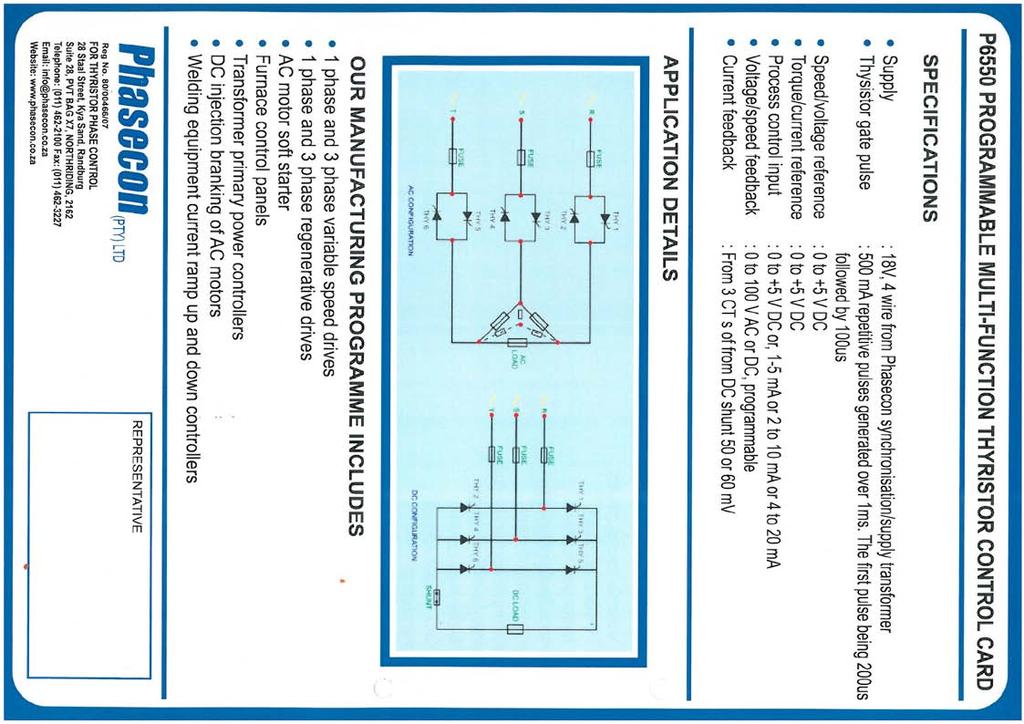
P6550 PROGRAMMABLE MULTI-FUNCTION THYRISTOR CONTROL CARD
|
|
|
- Collin Walsh
- 5 years ago
- Views:
Transcription

1 P6550 PROGRAMMABLE MULTI-FUNCTION THYRISTOR CONTROL CARD
2
3 T F info@phasecon.co.za 28 Staal Street, Kya Sand PO Box 28, Kya Sand 2163 We would like to introduce ourselves to your company with our manufacturing program. We manufacture single phase and three phase controllers for all kinds of applications. Listed below are a few applications that are the most common. We can supply these items in a chassis mount format or in boxes/panels; or with switch gear per your requirement. Primary / Secondary control of transformers Controlling of DC motors in single and bi-directional control Field controllers Controlled high voltage DC supplies Controlled low voltage supplies (with low ripple) Induction heaters (high frequency) i.e. hardening / melting Soft starters Slipring motor starters Furnaces controllers Battery charges Flying saw / shear croppers Controlling of tube mills Rectifiers Traction rectifiers Anodizing plants Vibrators Magnetizers
4 T / F / E /info@phasecon.co.za A /28 Staal Street, Kya Sand P /Suite 28, Private Bag X7, Northriding Basic description of P SWTITCH DESCRIPTION: SW1-1 Voltage feedback (20VDC) SW1-2 Voltage feedback (20VDC) SW1-3 Voltage feedback (20VDC) SW1-4 Voltage feedback (20VDC) SW1-5 Voltage amplifier loop (up = 1:1, down = 10:1) SW1-6 Thyristors enable (up firing engine) Switches 1,2,3,4 when in the OFF position will have a voltage drop of 20 Volts per switch. The voltage (DC) feedback is determined by the input of A4. Switch 5 in the ON position has a gain/reaction of 1:1 and in the OFF position has a gain/reaction of 10:1. Normal mode is for switch 6 to be on the ON position which will enable firing of the thyristors. SW2-1 Start boost SW2-2 Stall trip SW2-3 Current stability SW2-4 Current amplifier loop (up = 1:1, down = 10:1) SW3-5 Auxillary process loop SW2-6 Main control loop Switch 4 in the ON position has a gain/reaction of 1:1 and in the OFF position has a gain/reaction of 10:1. SW3-1 SW3-2 SW3-3 Input signal loading resistor of 1k Input signal loading resistor of 1k Input signal loading resistor of 1k 2. USER POT DESCRIPTION: N-MIN ACCEL N-STAB N-MAX I-STAB MINIMUM SPAN I-MAX Level above zero volts (A11) Ramp up and down time Voltage stability Maximum voltage Current stability Signal processing minimum adjustment Signal processing maximum adjustment Maximum current
5 3. FACTORY POT: MTA OFFSET Maximum trigger angle (factory set) Minimum trigger angle (factory set) 4. C.T. CURRENT CALACULATION: It should be noted the SHUNT feedback and CT feedback may not be used together. The resistor for the maximum demand current R124 (named BURDEN_RESISTOR) which is a 5 Watt resistor on the bottom right hand side of the control card is fitted by the factory for current that has been requested if you wish to change the burden resistor you must follow the following procedure: CURRDEM = CURRENT REQUIRED CT_RATIO EXAMPLE: CURRDEM = 45A 200/1 = BURDEN_RESISTOR = 3.0V CURRDEM = = 3V R The BURDEN-RESISTOR needed to run is 10ohms or a resistor as close as possible. If the voltage of the burden is higher than 5.23 volts the electronic trip will trip the card off. If you need to fit CT s always choose a CT value above maximum demand value. Note: if you are having any problems, please do not hesitate to contact us. Tel: Fax: info@phasecon.co.za T F info@phasecon.co.za 28 Staal Street, Kya Sand PO Box 28, Kya Sand 2163
6 DETAILED APPLICATION PROCEDURES Three phase DC controller using PHASECON complete units SET UP PROCEDURE Using P6555MB POWER card Switch settings ARMATURE FEEDBACK SW1 SW1:1 SW1:2 SW1:3 SW1:4 SW1:5 SW1:6 ON-UP ON-UP ON-UP ON-UP OFF-DWN ON-UP SW2 SW2:1 SW2:2 SW2:3 SW2:4 SW2:5 SW2:6 OFF-DWN OFF-DWN ON-UP OFF-DWN OFF-DWN ON-UP Using P6555MB connection card or PH1083. Witch setting (TACHO feedback (terminal 17 and 18)) SW1 SW1:1 SW1:2 SW1:3 SW1:4 SW1:5 SW1:6 OFF-DWN OFF-DWN OFF-DWN OFF-DWN OFF-DWN ON-UP SW2 SW2:1 SW2:2 SW2:3 SW2:4 SW2:5 SW2:6 OFF-DWN OFF-DWN ON-UP OFF-DWN OFF-DWN ON-UP Note that PHASECON light indication is: ON equals healthy state Connect incoming supply 1. Check that the PHASELOCK lamp comes ON (lamp on bottom right hand side of the control card) if the lamp is off, switch power off, swap incoming phases r and t and switch on 2. Check that the TRIP lamp is ON 3. Check the +12VOLTS, -12VOLTS lamp is ON 4. Set I-MAX pot anti-clockwise 5. Control pot REFERENCE VOLTAGE in the zero position 6. Start the card by enabling the start RUN light comes on 7. Turn control pot up slowly 8. With control pot at maximum position input adjust N-MAX for maximum voltage required if voltage remains the same you are running in current limit adjust N-MAX back to original position and adjust I-MAX 9. With control pot at maximum position input adjust I-MAX for maximum current required 10. If trip lamp goes off, reduce the size of the BURDEN-RESISTOR on the unit (the unit has tripped on over current) 11. Do not exceed the maximum current rating of the thyristors unit check rating plate for maximum rating 12. If you have a oscillation effect adjust N-STAB to optimise stability 13. System is now set for working condition
7 FURNACE SETUP PROCEDURE AC DRIVE SETUP: With current feedback only. Note: if the control card is connected via the ribbon cable then all control signals and connecgtions to be made on connection cards otherwise you will bypass built in protection. Connections to the connection card as per relevant drawings. Switch settings: SW1 SW1:1 SW1:2 SW1:3 SW1:4 SW1:5 SW1:6 ON-UP ON-UP ON-UP ON-UP ON-UP ON-UP SW2 SW2:1 SW2:2 SW2:3 SW2:4 SW2:5 SW2:6 OFF-DWN OFF-DWN ON-UP OFF-DWN OFF-DWN ON-UP Check that the connections have been done as per drawings depending on which interface card has been used as listed: PH1083 P6851 Note that PHASECON light indication is ON equals healthy state. 1. Check switch settings for correct setup 2. Power up 3. Check that the PHASELOCK lamp comes on (lamp on bottom right hand side of control card) if the lamp is off switch power off swap incoming phases R and T and switch on 4. Check that the following lights are on after powering up: TRIP, +12V, -12V and PHASELOCK 5. Set I-MAX pot anti-clockwise 6. All measurements to be made on P6550 control card 7. The 4-20mA is set correctly when the cards leaves the factory but if it needs to be set follow these procedures. You do not need to be in run mode to setup 4-20mA input range measure with a DC volt meter at terminals A3 (0 volts) and terminal A2 (+ signal) abd adjust MINIMUM and SPAN to halfway mark between max and min position 8. Set controller to 4mA output adjust MINIMUM pot )measure Set controller to 20mA outpur adjust SAPN pot (measure positive 5.11V) 10. Start the card by enabling the run/start sicrcuit 11. RUN light is now on 12. At 20mA input adfjust I-MAX pot to maximum demanded current 13. Aty maximum demand measure DC volts on terminal 4 (+) and 7 (-) that the voltage is between +2 volts and 3.5 volts (ideal). If you exceed 5.23 VDC the card will trip due to over current. 11. Do not exceed the maximum current rating of the thyristors unit check rating plate for maximum rating 12. If you have a oscillation effect adjust N-STAB to optimise stability 13. System is now set for working condition
8 RECTIFIER SETUP: Switch settings: SW1 SW1:1 SW1:2 SW1:3 SW1:4 SW1:5 SW1:6 ON-UP ON-UP ON-UP ON-UP OFF-DWN ON-UP SW2 SW2:1 SW2:2 SW2:3 SW2:4 SW2:5 SW2:6 OFF-DWN OFF-DWN ON-UP OFF-DWN OFF-DWN ON-UP * note Note 1: ON for testing, normal operation = OFF 1. Connect control card as per drawing of a typical plating type rectifier 2. Before you power up make sure that K2 and R on the SYNC transformer is zero ohms and K4 and s, K6 and T respectively 3. Disconnect the wire from the shunt to A10 and check that you have positive mv on the wire going to terminal A10 (if the shunt feedback used) and put SW2:4 in the ON position and I-MAX clockwise 4. Lamps that must be ON, on power up -12V, +12V, PHASELOCK, TRIP lamps in the ON state are healthy 5. Set switches as indicated above 6. Switch power ON 7. Voltage control pot at zero 8. Current control pot at zero 9. No load must be connected 10. Start card 11. RUN lamp must be on 12. Turn current control pot up slowly to maximum 13. Turn voltage control pot up slowly to maximum 14. Adjust N-MAX pot to required maximum voltage read with multimeter on the bussbars to check meter on rectifier 15. Turn voltage control pot down slowly to minimum 16. Stop card 17. Connect the macximum load 18. Start card 19. Turn voltage control pot up slowly, until amo meter indicates a small load, measure to ensure you get positive mv from wire that goes to A10 (shunt) 20. Power off 21. If positive feedback from the shunt connect to A10. Turn I-MAX pot anti clockwise and switch SW2:4 OFF current feedback ON 22. Start card 23. Turn voltage and current pots to maximum 24. Adjust I-MAX to maximum allowed current of rectifier 25. Turn current control pot down and up and check that current follows pot 26. System is now ready for use 27. If oscillation occurs adjust N-STAB
9

10 FAULT FINDING: It is advisable to connect lamps/bulbs in star configuration with the star point connected to neutral (when testing AC config). If available and the other side of the globe to the output of the thyristors. No lights on control card of PHASELOCK light OFF: 1. Ribbon cable not plugged in 2. Check incoming power 3. Check all three phases for voltage 4. Check fuses 5. Check synchronising transformer for 18 volts AC at terminal U, V, W to terminal A9 on control card PHASELOCK light off: 1. Incoming fuses blown 2. Phase rotation wrong 3. Check synchronising transformer for 18 Volts AC at terminal U, V, W to terminal A9 on control card Not operating: 1. Is PHASELOCK not on 2. Is TRIP light on 3. Is RUN light on 4. Is instrument giving output 5. Has the thermal cut-out opened due to heatsink overheating or fan stopping Power faults: Still drawing power (current) when the run light is off 1. Thyristor blown 2. To check that the thyristor is blown measure with the power off, measure with an ohm meter and if it measures almost zero ohms the thyristor is blown (the measurement must be on the incoming of the thyristor and the output or measure K1 to K2, K3 to K4 and K5 to K6). Not drawing current on a phase while under normal running operation: 1. Load faulty 2. Thyristor faulty 3. Control card faulty If you are still having problems please phone us as we can fix most faults over the phone with the following information: What lights are on or how bright they are shining DC volts on A2 and A3; note that A3 = 0V 0-5V) DC volts on A8 and A3 0-5V) DC volts on 4 and A3 current pot maximum) AC volts K1 to K2 (reference pot input (current pot input (with reference, and (with reference, and
11
12
13
14
P4500 PROGRAMMABLE MULTI-FUNCTION THYRISTOR CONTROL CARD
 P4500 PROGRAMMABLE MULTI-FUNCTION THYRISTOR CONTROL CARD T 011 462 2100 F 011 462 3227 info@phasecon.co.za www.phasecon.co.za 28 Staal Street, Kya Sand PO Box 28, Kya Sand 2163 We would like to introduce
User Guide 4Q kW D.C.Motor Regenerative Speed Controller. Part Number: Issue Number: 3
 User Guide 4Q2 0.55-7.5kW D.C.Motor Regenerative Speed Controller Part Number: 0400-0042-03 Issue Number: 3 General Information The manufacturer accepts no liability for any consequences resulting from
Burden Fuse Rating Resistor SAF / SAK6 1NM 10mm M8 12NM SAF / SAK10 2NM 16mm M8 12NM
 Contents Section Page 1.0 Introduction 1 2.0 Specification 1-4 3.0 Installation 5-8 4.0 Programming 9-10 5.0 Menus 10-12 6.0 Fault Finding/Diagnostics 12-13 7.0 Communication 13 8.0 Setting Up 13-16 1.0
Model ER-340XRi / ER-680XRi / ER-1220XRi DC drive product manual HG iss 9 1
 Model ER-340XRi / ER-680XRi / ER-1220XRi DC drive product manual HG102909 iss 9 1 This drive is an isolated 4 Quadrant speed controller for shunt wound or permanent magnet motors. It utilises speed feedback
Model 340i / 680i / 1220i DC drive product manual HG iss 8 1
 Model 340i / 680i / 1220i DC drive product manual HG102938 iss 8 1 Sprint Electric Limited, Arundel, UK Tel. +44 (0)1903 730000 Fax. +44 (0)1903 730893 Email. info@sprint-electric.com www.sprint-electric.com
DC3N Non-Regenerative DC Drives
 PRICING 1/8-1.0 HP @ 115 VAC, 1-Ph, 50/60 Hz: 90 VDC Armature 1/4-2.0 HP @ 230 VAC, 1-Ph, 50/60 Hz: 180 VDC Armature For the Operation of Permanent Magnet DC Motors Only Product Features: DC3N Plate Model
NEMA 1, NEMA 4X and Chassis Mount Adjustable Speed Controls for DC Motors
 Made in the U.S.A. NEMA 1, NEMA 4X and Chassis Mount Adjustable Speed Controls for DC Motors Nema Enclosed DC Control Specifications Catalog Number BC140 or Features BC138 BC139 BC140-FBR BC154 BC160 BCWD140
amp ramp Operators Manual Page 1 Saftronics 2S Ltd Turnbridge Mills Quay Street Huddersfield West Yorkshire HD1 6QT
 amp ramp Operators Manual Saftronics S Ltd Turnbridge Mills Quay Street Huddersfield West Yorkshire HD 6QT Tel: 0484 530893 Fax: 0484 550500 Website:www.saftronics.co.uk E-Mail: sales@saftronics.co.uk
1/4HP - 7.5HP 120/240/277 VOLTS 50/60HZ
 Installation & Operating Procedures DG2 Series SINGLE PHASE CONVERTERS 1/4HP - 7.5HP 120/240/277 VOLTS 50/60HZ TABLE OF CONTENTS 1.0 DESCRIPTION... Pg. 1 2.0 INSTALLATION AND START-UP... Pg. 3 3.0 DRAWING
Fincor Series 2230 MKII/2240
 Fincor Series 2230 MKII/ Fincor Series 2200 regenerative drives are ideal for your more demanding applications. They feature flexibility with ratings up to 5 horsepower. The Series 2230 MKII offers new
WDC CONTROL SERIES. Instruction Manual. Variable Speed DC Control
 WDC CONTROL SERIES Instruction Manual Variable Speed DC Control P.O. Box 307 1 Grove Street - Suite 201B Pittsford, NY 14534 Phone: (800) 808-2131 Fax: (800) 711-1616 www.worldwideelectric.net TABLE OF
Thyristor Power Controllers for Resistive and Inductive loads (Product Code 21.3)
") Thyristor Power Controllers for Resistive and Inductive loads (Product Code 21.3) 1 Model Wise Descriptions: Sr. No Model Product Description 21.3.1 POW-1 Single Phase SCR Power Controller for single phase
Thyristor Power Controllers for Resistive and Inductive loads (Product Code 21.3) 1 Model Wise Descriptions: Sr. No Model Product Description 21.3.1 POW-1 Single Phase SCR Power Controller for single phase
Observe all necessary safety precautions when controlling the soft starter remotely. Alert personnel that machinery may start without warning.
 Introduction OPERATING INSTRUCTIONS: MCD REMOTE OPERATOR Order Codes: 175G94 (for MCD 2) 175G361 + 175G9 (for MCD 5) 175G361 (for MCD 3) 1. Introduction 1.1. Important User Information Observe all necessary
5001TCP SPEED CONTROLLER
 VARIABLE SPEED DRIVE CONTROLLER INSTALLATION AND SETTING UP MANUAL 5001TCP SPEED CONTROLLER With PC101 Torque Limit Control WARNING Disconnect all incoming power before working on this equipment. Follow
MaxPak Plus Analog DC V S Drive
 Three-Phase 3-600 HP non-regenerative and 5-150 HP regenerative drives Designed to accommodate a wide range of industrial requirements, the DC V S Drive has been widely applied worldwide. Selected ratings
User Guide. Mini Maestro. Variable Speed Drive for Permanent-magnet DC Servo-motors. Part Number: Issue: 5.
 User Guide Mini Maestro Variable Speed Drive for Permanent-magnet DC Servo-motors Part Number: 0470-0009-05 Issue: 5 www.controltechniques.com Safety Information Persons supervising and performing the
Motor Controllers AC Semiconductor Motor Controller Type RSHP Flexy
 otor Controllers AC Semiconductor otor Controller Type RSHP Flexy Soft starting and stopping of 3-phase squirrel cage motors Low surge and vibration-free starting User-selected ramping profiles Integral
CN0055 & CN0055B DC to DC NEGATIVE RESISTANCE SPEED CONTROL
 CN0055 & CN0055B DC to DC NEGATIVE RESISTANCE SPEED CONTROL 0 M P A N Y 3879 SOUTH MAIN STREET 714-979-6491 SANTA ANA, CALIFORNIA 92707-5710 U.S.A. This manual contains information for installing and operating
James Hamilton Electrical Pty Ltd (Inc in Qld) A.C.N trading as. Power Drive Systems. Generator Control Specialists
 A.C.N trading as. Power Drive Systems. Generator Control Specialists") James Hamilton Electrical Pty Ltd (Inc in Qld) A.C.N. 010 848 389 trading as Power Drive Systems Generator Control Specialists 48A Ainsdale Street Telephone: 0500 800 225 P.O. Box 30 West Chermside, Qld
James Hamilton Electrical Pty Ltd (Inc in Qld) A.C.N. 010 848 389 trading as Power Drive Systems Generator Control Specialists 48A Ainsdale Street Telephone: 0500 800 225 P.O. Box 30 West Chermside, Qld
Mini Maestro Drive. User Guide. Variable Speed Drive for Permanentmagnet DC Servo-motors. Part Number: Issue Number: 4
 EF User Guide Mini Maestro Drive Variable Speed Drive for Permanentmagnet DC Servo-motors Part Number: 0470-0009 Safety Information Persons supervising and performing the electrical installation or maintenance
MAXIMUM OUTPUT AC SUPPLY INPUT SPEED RANGE USER ADJUSTMENT EXTERNAL CONTROL CONTROL ACTION INSTALLATION
 1 DRM050IR / DRM100I / DRM200IR DC Motor Controller Product Manual This drive is an isolated single direction speed controller for shunt wound or permanent magnet motors. It utilizes speed feedback from
G203V / G213V MANUAL STEP MOTOR DRIVE
 G203V / G213V MANUAL STEP MOTOR DRIVE PRODUCT DIMENSIONS PHYSICAL AND ELECTRICAL RATINGS Minimum Maximum Units Supply Voltage 18 80 VDC Motor Current 0 7 A Power Dissipation 1 13 W Short Circuit Trip 10
2.0 CONSTRUCTION 3.0 OPERATION. SA-1 Generator Differential Relay - Class 1E 2.5 TRIP CIRCUIT
 41-348.11C SA-1 Generator Differential Relay - Class 1E 2.0 CONSTRUCTION The type SA-1 relay consists of: Restraint Circuit Sensing Circuit Trip Circuit Surge Protection Circuit Operating Circuit Amplifier
User Guide. Mini Maestro Drive. Variable Speed Drive for Permanent-magnet DC Servo-motors. Part Number: Issue Number: 2
 User Guide Mini Maestro Drive Variable Speed Drive for Permanent-magnet DC Servo-motors Part Number: 0470-0005 Issue Number: 2 Safety Information Persons supervising and performing the electrical installation
SE-3SCR-LM MANUAL MOTOR LOAD MANAGER
 3714 Kinnear Place Saskatoon, SK Canada S7P 0A6 Ph: (306) 373-5505 Fx: (306) 374-2245 www.littelfuse.com/relayscontrols SE-3SCR-LM MANUAL MOTOR LOAD MANAGER MARCH 5, 2013 REVISION 4 MOTOR LOAD MANAGER
Applications: Conveyors, machine tools and other applications requiring adjustable speed. Mult. Sym.
 HVAC Farm Duty Fractional Horsepower DC Speed Controls for PMDC DC & Controls 1/15 thru 1/4 115 VAC Single Phase 50/60 Hz. Applications: Conveyors, machine tools and other applications requiring adjustable
Series 2330MKII. Single-Phase. Adjustable-Speed. DC Motor Controllers (1/6 3 HP) BOOK 0958-B
 BOOK 0958-B") Series 2330MKII Single-Phase Adjustable-Speed DC Motor Controllers (1/6 3 HP) Control Techniques 3750 East Market Street York, PA 17402-2798 717-751-4200, FAX 717-751-4263 www.fincor.net BOOK 0958-B SERIES
Series 2330MKII Single-Phase Adjustable-Speed DC Motor Controllers (1/6 3 HP) Control Techniques 3750 East Market Street York, PA 17402-2798 717-751-4200, FAX 717-751-4263 www.fincor.net BOOK 0958-B SERIES
Thyristor Power Regulators
 READY TO USE SCR-BASED HIGH PERFORMANCE & ENERGY EFFICIENT 1-PHASE, 2-PHASE AND 3-PHASE POWER REGULATORS SCR POWER REGULATORS FROM 15 AMPS TO 750 AMPS AND HIGHER Description RADIX brings you a full range
TABLE OF CONTENTS WARRANTY. 1 INTRODUCTION. 2 CONTROL FEATURES. 2 HEATSINK DIMENSIONS. 2 SPEEDPOT KIT ASSEMBLY. 3 MOUNTING PROCEDURE.
 250G CONTROL SERIES CONTROLS Instruction Manual Variable Speed DC Control P.O. Box 10 5000 W. 106th Street Zionsville, Indiana 46077 Phone (317) 873-5211 Fax (317) 873-1105 www.dartcontrols.com TABLE OF
G213V STEP MOTOR DRIVE REV 7: March 25, 2011
 Thank you for purchasing the G213V drive. The G213V is part of Geckodrive s new generation of CPLD-based microstep drives. It has short-circuit protection for the motor outputs, over-voltage and under-voltage
EUROTHERM ONTROLS. Two phase thyristor power switches. Product data
 TC2000 TC2001 EUROTHERM ONTROLS Two phase thyristor power switches Product data TC2000 TC2001 Thyristor power switches Compact, two phase thyristor power switches for electrical heating applications from
300% Motor full load amps at 80 seconds, 400% Motor full load amps at 35 seconds
 Digital Soft Start Controls Soft Starters & 9 thru 900 s 208-460V 50/60 Hz. 9 thru 900 s 208-575V 50/60 Hz. Farm Duty Applications: Controlled ramp start and stop, minimize spillage in material handling,
USERS MANUAL MCD REMOTE OPERATOR
 USERS MANUAL MCD REMOTE OPERATOR Order Code: 175G9004, 175G3061 Contents Contents Introduction...2 Important User Information...2 General Description...2 Symbols Used in this Manual...2 Installation...3
3.5 Amp Bi-polar stepper motor drive MSE570 Evo 2
 3.5 Amp Bi-polar stepper motor drive MSE57 Evo 2 Features Bi-polar drive with pre-set drive currents up to 3.5 Amps per phase Increased operating voltage up to 48 V ½ step drive option for improved damping
2122H. Arm Field Arm Field 1/8-1/ / /8-1/ / / /
 Non-Regen Drives Non-regenerative drives are typically used on applications which primarily motor in one direction and stopping is achieved through friction or infrequent use of a dynamic braking resistor.
BLDC SPEED CONTROL INSTRUCTION MANUAL Low voltage Brushless DC control
 BLDC SPEED CONTROL INSTRUCTION MANUAL Low voltage Brushless DC control Phone 712.722.4135 groschopp.com 420 15th St NE, Sioux Center, IA 51250 Toll-Free 800.829.4135 Email sales@groschopp.com FAX 712.722.1445
CURTIS TRANSISTOR MOTOR CONTROLLER
 CURTIS TRANSISTOR MOTOR CONTROLLER W40-60XL, B40-60XL [D135]; N30FR [A217]; R30ES [B174]; R30XMS [C174]; R30XMS2 [D174]; W60-80XT [E135]; B60-80XT [B199]; C60-80XT [B199]; W40XT [A218]; W45XT [A215, B215];
to allow a current in one circuit to operate a switch in another circuit to protect a circuit by melting if the current becomes too large
 1 What is the function of a relay? to allow a current in one circuit to operate a switch in another circuit to prevent an electric shock by earthing a metal case to protect a circuit by melting if the
AF-17 Electronic Positioner Installation, Operation and Maintenance Instructions
 WCAIM2031 AF-17 Electronic Positioner Installation, Operation and Maintenance Instructions MODELS 20 For AF-17 Boards Mounted Inside 10-23 75 Actuator. 30 For AF-17 Boards Mounted Inside 25-30 75 Actuator.
TRIPS AND FAULT FINDING
 WWW.SDS.LTD.UK 0117 9381800 Trips and Fault Finding Chapter 6 6-1 TRIPS AND FAULT FINDING Trips What Happens when a Trip Occurs When a trip occurs, the drive s power stage is immediately disabled causing
ARM V FDBK ENSURE MOTOR IS NOT ROTATING DURING POWER UP STILL FAULTS? YES ENSURE ARMATURE WIRING IS ISOLATED FROM ANY OTHER POWER LEADS STILL FAULTS?
 ARM V FDBK ENSURE MOTOR IS T ROTATING DURING POWER UP This fault can only happen in the first 3 seconds after power up. The processor looks at the armature voltage. The voltage needs to be near 0. Possible
SCR POWER REGULATORS & HEATING CONTROL PANELS. 1/2/3-Phase 15 ~ 750+ Amps 220 ~ 480 V AC.
 SCR POWER REGLATORS & 1/2/3-Phase 15 ~ 750+ Amps 220 ~ 480 V AC SCR POWER REGLATORS & Radix SCR Power Regulators Radix offers a full range of SCR Power Regulators as well as SCR Heating Control Panels.
SURE TRIP RETRO KITS
 RMS CURRENT MEASUREMENT with SURE TRIP RETRO KITS Circuit Breaker Solid State Controls with SURE TRIP LOGIC The Sure Trip Solid State Tripping Systems Have Been Designed, Tested And Produced To all Applicable
2.1 Warnings & Agency Approvals Electrical Connections - Specifications Standard Wiring Configurations...2 4
 CHAPTER ELECTRICAL 2 INSTALLATION Contents of this Chapter... 2.1 Warnings & Agency Approvals..................2 2 2.1.1 Isolation..............................................2 2 2.1.2 Electrical Power
Powerframes - Power Electronics
 Powerframes - Power Electronics 70 series The study of power electronic devices, motor drives and circuits is an essential part of any course on power electrical systems. The Series 70 Power Electronics
BLDC SPEED CONTROL INSTRUCTION MANUAL Line voltage Brushless DC control
 BLDC SPEED CONTROL INSTRUCTION MANUAL Line voltage Brushless DC control Phone 712.722.4135 groschopp.com 420 15th St NE, Sioux Center, IA 51250 Toll-Free 800.829.4135 Email sales@groschopp.com FAX 712.722.1445
DENISON HYDRAULICS Jupiter 500 Driver Card Series S
 Back to Content DENISON HYDRAULICS Jupiter 500 Driver Card Series S20-11712-0 Publ. 9-AM681 E-Mail: denison@denisonhydraulics.com Internet: http://www.denisonhydraulics.com SYSTEM FEATURES SYSTEM FEATURES
XENON POWER SUPPLY 4000 Watt Gladiator IV
 XENON POWER SUPPLY 4000 Watt Gladiator IV 220 Volt Equipment Type 62-00049 Rev. February 2003 STRONG INTERNATIONAL a division of Ballantyne of Omaha, Inc. 4350 McKinley Street Omaha, Nebraska 68112 USA
5001TCP SPEED CONTROLLER
 INSTALLATION AND SETTING UP MANUAL 5001TCP SPEED CONTROLLER WARNING Disconnect all incoming power before working on this equipment. Follow power lockout procedures. Use extreme caution around electrical
Features and Benefits. Control Features
 Features and Benefits AC induction motors have become increasingly dominant in industrial facilities worldwide. Manufacturers faced with increasing pressure to control costs have recognized that motor
SCR Power Controllers
 SCR Power Controllers Instruction Manual SCR POWER CONTROLLERS TABLE OF CONTENTS General Description and Specifications...1 Firing Modes....2 Installation and Wiring...4 Operation...9 Troubleshooting...15
INSTALLATION AND SET-UP MANUAL FOR THE NEW: AVR-07. A CONTROLPAK AVR Automatic Voltage Regulator for three-phase and single-phase alternators
 INSTALLATION AND SET-UP MANUAL FOR THE NEW: AVR-07 A CONTROLPAK AVR Automatic Voltage Regulator for three-phase and single-phase alternators This is a premium quality product at a reasonable price, and
TRAC-3 TENSION READOUT AND CONTROL
 Magnetic Power Systems, Inc. 1626 Manufacturers Drive. Fenton, MO 63026 Tel: 636.343.5550 Fax: 636.326.0608 magpowr@magpowr.com INSTRUCTION MANUAL TRAC-3 READOUT AND CONTROL For Control of Magnetic Particle
SURE-TRIP OEM RELACEMENT TRIP UNIT
 RMS CURRENT MEASUREMENT with SURE-TRIP OEM RELACEMENT TRIP UNIT Update Circuit Breaker Solid State Controls with SURE-TRIP LOGIC The SURE-TRIP Solid State Tripping Systems Have Been Designed, Tested And
Powerframes - Power Electronics
 Powerframes - Power Electronics 70 series The study of power electronic devices, motor drives and circuits is an essential part of any course on power electrical systems. The Series 70 Power Electronics
INSTRUCTION MANUAL FOR. VOLTAGE REGULATOR Model: APR Part Number:
 INSTRUCTION MANUAL FOR VOLTAGE REGULATOR Model: APR 125-5 Part Number: 9 1688 00 100 Publication Number: 9 1688 00 990 Revision H: 07/2001 CONTENTS SECTION 1 GENERAL INFORMATION...1-1 DESCRIPTION... 1-1
PART NO CP-DOOR FRONT PANEL WINDOW PART NO CP-DOOR FRONT PANEL SECOND WINDOW PART NO CP-DOOR LOCK PART NO. 5026
 5010 CP-DOOR FRONT PANEL WINDOW 5015 CP-DOOR FRONT PANEL SECOND WINDOW 5025 CP-DOOR LOCK 5026 CP-DOOR LOCKING CYLINDER 5027 CP MOUNTING BRACKET (PACKET OF 4) 5030 OBSOLETE CP-DOOR PUSH-BUTTON GREEN (HEAD
OPERATION AND INSTALLATION MANUAL. Solid State Reduced Voltage Starters. Cutler-Hammer
 OPERATION AND INSTALLATION MANUAL Solid State Reduced Voltage Starters Cutler-Hammer FOR YOUR SAFETY Only qualified personnel should install this equipment, after first reading and understanding all the
3. OPERATION 2.1. RESTRAINT CIRCUIT 2.6. INDICATING CIRCUIT 2.2. OPERATING CIRCUIT 2.7. SURGE PROTECTION CIRCUIT 2.3.
 41-348.1H Type SA-1 2.1. RESTRAINT CIRCUIT The restraint circuit of each phase consists of a center-tapped transformer, a resistor, and a full wave rectifier bridge. The outputs of all the rectifiers are
Graham. Vari Speed S1000 Instruction Manual. TRANSMISSIONS, Inc. Installation, Operation and Maintenance Manual
 Graham TRANSMISSIONS, Inc. Installation, Operation and Maintenance Manual Vari Speed S1000 Instruction Manual TABLE OF CONTENTS Introduction 4 Unit Features 5 Operating Conditions 6 Specifications 7 Ratings
XENON POWER SUPPLY Watt
 XENON POWER SUPPLY 3000-5000 Watt 220 Volt Equipment Type 62-00016 62-00017 62-00004 (Export) Rev. February 2006 STRONG INTERNATIONAL a division of Ballantyne of Omaha, Inc. 4350 McKinley Street Omaha,
A1P OPERATING MANUAL
 A1P OPERATING MANUAL TABLE OF CONTENTS Introduction... p. 2 Features... p. 2 Description... p. 3 Theory of Operation... p. 3 Installation... p. 4 Electrical Connections... p. 5 Options... p. 6 Warranty...
ABB Softstarter Benefits Charnchanok Thongprad
 ABB Softstarter Benefits Charnchanok Thongprad tomation Technology Products AB Control - 1 - - Why Softstarters? Benefits for the Electrical network Reduces voltage drops on networks Minimizes starting
ADVR-12. Hybrid Universal Analog Digital Voltage Regulator Operation Manual
 ADVR-12 Hybrid Universal Analog Digital Voltage Regulator Operation Manual Adapter plugs for Digital Regulator Self Excited Automatic Voltage Regulator For use in Brushless PMG and Auxiliary Winding 4501
POWER SUPPLY MODEL XP-800. TWO AC VARIABLE VOLTAGES; 0-120V and 7A, PLUS UP TO 10A. Instruction Manual. Elenco Electronics, Inc.
 POWER SUPPLY MODEL XP-800 TWO AC VARIABLE VOLTAGES; 0-120V and 0-40V @ 7A, PLUS 0-28VDC @ UP TO 10A Instruction Manual Elenco Electronics, Inc. Copyright 1991 Elenco Electronics, Inc. Revised 2002 REV-I
Boston Gear Ratiotrol
 Boston Gear Ratiotrol DC Motor Speed Control Installation and Operation Doc. No. 3721 RG1 and RG2 Models 1/6-1 HP GENERAL INFORMATION DESCRIPTION Series RG Controllers statically convert single-phase AC
DC Variable Speed Drive Panel
 DC Variable Speed Drive Panel Installation, Operation & Maintenance Instruction Manual Bulletin #: CC-IOM-0103-D Manufacturers of Quality Pumps, Controls and Systems ENGINEERED PUMP OPERATIONS 2883 Brighton
715B CONTROL SERIES. Instruction Manual Line Voltage DC Brushless Motor Control CONTROLS. Phone (317) Fax (317)
 Fax (317)") 715B CONTROL SERIES CONTROLS Instruction Manual Line Voltage DC Brushless Motor Control LT715B (IM-715B-0100) P.O. Box 10 5000 W. 106th Street Zionsville, Indiana 46077 Phone (317) 873-5211 Fax (317) 873-1105
715B CONTROL SERIES CONTROLS Instruction Manual Line Voltage DC Brushless Motor Control LT715B (IM-715B-0100) P.O. Box 10 5000 W. 106th Street Zionsville, Indiana 46077 Phone (317) 873-5211 Fax (317) 873-1105
Softstarters. Softstarters Type SSM Medium voltage ,800V 1
 Medium voltage 2300 13,800V 1 Description Fused disconnect switch with blown fuse indicators and door safety interlocks rated for load break/fault make with automatic grounding arm Inline isolation vacuum
AGELKOM CAP04 Plasma and Oxy Fuel Torch height control for sheet metal cutting machines Height Sensor & Controller
 6 PIN INTERFACE BNC HEIGHT CONTROL KNOB CAP 04 CAPACITIVE HEIGHT CONTROLLER DOWN IN POSITION UP TOUCH CABLE FAULT AGELKOM CAP04 Plasma and Oxy Fuel Torch height control for sheet metal cutting machines
CENTROIDTM. AC Brushless Drive. Product Spec Sheet
 4 Axis, up to 2 KW motors Brake Output for each axis Overtemp and Overcurrent Protection All-software Configuration Self-cooled Fiber Optic Control CENTROIDTM AC Brushless Drive Product Spec Sheet AC Brushless
12 Series Linear Electric Actuator Installation, Operation & Maintenance Manual
 12 Series Linear Electric Actuator Installation, Operation & Maintenance Manual TELEPHONE: +1-859-727-7890 TOLL FREE: +1-800-662-9424 FAX: +1-859-727-4070 E-MAIL: DVOGES@INDELAC.COM MROBINSON@INDELAC.COM
AVR Hybrid Universal Analog Digital Voltage Regulator Operation Manual
 AVR 63-12 Hybrid Universal Analog Digital Voltage Regulator Operation Manual Self Excited Automatic Voltage Regulator For use in Brushless PMG and Auxiliary Winding 1. SUMMARY The AVR 63-12 is a totally
Applications: General purpose industrial use with permanent magnet or shunt wound DC motors. Description
 NEMA 1 Enclosed DC Controls for PMDC and Shunt Wound DC & Controls 1/100 thru 2 Hp 115/230 VAC Single Phase 50/60 Hz. Applications: General purpose industrial use with permanent magnet or shunt wound DC
CABINET REEL OPERATING INSTRUCTIONS
 CABINET REEL OPERATING INSTRUCTIONS (Rev. 1) RAPID-AIR CORPORATION 4601 KISHWAUKEE ST. ROCKFORD, IL 61109-2925 Phone: (815) 397-2578 Fax: (815) 398-3887 Web Site: www.rapidair.com OPERATING INSTRUCTIONS
RBD Series. Installation and Maintenance Manual. An Altra Industrial Motion Company
 RBD Series Installation and Maintenance Manual An Altra Industrial Motion Company TABLE OF CONTENTS INTRODUCTION... 3 CONTROL FEATURES... 3 HEATSINK DIMENSIONS... 3 SPEEDPOT KIT ASSEMBLY... 4 MOUNTING
RATE CONTROLLED TORQUE WRENCH TESTER
 RATE CONTROLLED TORQUE WRENCH TESTER OPERATOR S HANDBOOK (PART NO. 34078) ISSUE 8 NORBAR TORQUE TOOLS LTD, Beaumont Road, Banbury, Oxfordshire, OX16 1XJ, UNITED KINGDOM Tel : + 44 (0) 1295 270333, Fax
The Safari Portable Flash Generator
 The Safari Portable Flash Generator The Lencarta Safari is a battery powered portable flash generator and dedicated flash heads. The Safari generator is specifically designed to be used where mains power
TEL: G&C Electronics CC E. T.
 TEL: +27 21 448 6774 G&C Electronics CC FAX: +27 21 447 7794 E. T. CK 89/31531/23 E-mail : etsystems@icon.co.za Internet: www.et.co.za 15 Nelson Road P.O. Box 34524 Observatory Groote Schuur Cape Town
DUAL SWIVEL REEL OPERATING INSTRUCTIONS
 DUAL SWIVEL REEL OPERATING INSTRUCTIONS MODELS 100 & 1000 SERIES RAPID-AIR CORPORATION 4601 KISHWAUKEE ST. ROCKFORD, IL 61109-2925 Phone: (815) 397-2578 Fax: (815) 398-3887 Web Site: www.rapidair.com OPERATING
DC3E Non-Regenerative DC Drive User Guide 1/4 to 2 HP, 115/230 VAC M/N DC3N-12D AI M/N DC3N-12D-4X-010-AI
 250-0287-rev2.qxd 3/12/01 10:27 AM Page a DC3E Non-Regenerative DC Drive User Guide 1/4 to 2 HP, 115/230 VAC M/N DC3N-12D-00-010-AI M/N DC3N-12D-4X-010-AI Instruction Manual D2-3452-1 250-0287-rev2.qxd
RCP200 Series Motor Controls. Instruction Manual Model RCP Model RCP Model RCP202-BC1 Model RCP202-BC2 Model RCP205-BC2
 RCP200 Series Motor Controls Instruction Manual Model RCP202-000 Model RCP205-000 Model RCP202-BC1 Model RCP202-BC2 Model RCP205-BC2 You ve just purchased the best! Congratulations! You ve just purchased
Maintenance Manual 13 AMPERE POWER SUPPLY 19A704647P1-P3. Mobile Communications LBI-31801C
 C Mobile Communications 13 AMPERE POWER SUPPLY 19A704647P1-P3 CAUTION THESE SERVICING INSTRUCTIONS ARE FOR USE BY QUALI- FIED PERSONNEL ONLY. TO AVOID ELECTRIC SHOCK DO NOT PERFORM ANY SERVICING OTHER
Installation and Maintenance Instructions. World Leader in Modular Torque Limiters. PTM-4 Load Monitor
 World Leader in Modular Torque Limiters Installation and Maintenance Instructions PTM-4 Load Monitor 1304 Twin Oaks Street Wichita Falls, Texas 76302 (940) 723-7800 Fax: (940) 723-7888 E-mail: sales@brunelcorp.com
ENGINE GOVERNING SYSTEMS LSM672 LOAD SHARING MODULE. GOVERNORS AMERICA CORP. 720 Silver Street Agawam, MA , USA MEMBER
 ENGINE GOVERNING SYSTEMS LSM672 LOAD SHARING MODULE MEMBER GOVERNORS AMERICA CORP. 720 Silver Street Agawam, MA 01001-2907, USA LSM672 LOAD SHARING MODULE PRODUCT TECHNICAL INFORMATION PTI 4000 AUGUST
Troubleshooting Bosch Proportional Valves
 Troubleshooting Bosch Proportional Valves An Informative Webinar Developed by GPM Hydraulic Consulting, Inc. Instructed By Copyright, 2009 GPM Hydraulic Consulting, Inc. TABLE OF CONTENTS Bosch Valves
SOLID STATE POWER CONTROLLERS ACL-series AC1-series AC3-series ACF3-series DAC3- series
 H & C SOLID STATE POWER CONTROLLERS ACL-series AC1-series AC3-series ACF3-series DAC3- series OPERATION This power controller is designed to regulate a resistive load by switching the load on and off in
SERIES 2600/2610 SINGLE-PHASE ADJUSTABLE-SPEED DC MOTOR CONTROLLERS (1/6-5 HP)
") Rev. 11/01 SERIES 2600/2610 SINGLE-PHASE ADJUSTABLE-SPEED DC MOTOR CONTROLLERS (1/6-5 HP) TABLE OF CONTENTS SECTION TITLE PAGE I GENERAL INFORMATION 1 Introduction 1 General Description 1 Model Types 1
Rev. 11/01 SERIES 2600/2610 SINGLE-PHASE ADJUSTABLE-SPEED DC MOTOR CONTROLLERS (1/6-5 HP) TABLE OF CONTENTS SECTION TITLE PAGE I GENERAL INFORMATION 1 Introduction 1 General Description 1 Model Types 1
MD10. Engine Controller. Installation and User Manual for the MD10 Engine Controller. Full Version
 MD10 Engine Controller Installation and User Manual for the MD10 Engine Controller. Full Version File: MartinMD10rev1.4.doc May 16, 2002 2 READ MANUAL BEFORE INSTALLING UNIT Receipt of shipment and warranty
Gate & Door Controller with LCD and Intelligent Technology
 2nd Edition Gate & Door Controller with LCD and Intelligent Technology 24Sv1 and 12Sv1 Motor Controllers Setup and Technical information for single motor controller for gates & doors Includes latest Intelligent
CV - 6SL INSTRUCTION MANUAL 6000W POWER SUPPLY
 CV - 6SL INSTRUCTION MANUAL 6000W POWER SUPPLY 1 TABLE OF CONTENTS 1.0 Specification 5 2.0 Installation 7 2.1 Rack Mounted 7 2.2 Cooling 7 2.3 Filament Module 8 2.4 Electrical Power Input 8 2.5 Grounds
Film-Tech. The information contained in this Adobe Acrobat pdf file is provided at your own risk and good judgment.
 Film-Tech The information contained in this Adobe Acrobat pdf file is provided at your own risk and good judgment. These manuals are designed to facilitate the exchange of information related to cinema
LG Air Conditioning Universal & Multi Split Fault Codes Sheet. Universal and Multi Split Units
 Universal and Multi Split Units If there is a fault on any LG Universal or Multi unit, a two digit number will appear on the remote controllers led display. If the unit does not have a remote controller
User s Manual: SMARTSTART Series. Models: 6R15 6R830 6V400 6V630
 User s Manual: SMARTSTART 6000 Series Models: 6R15 6R830 6V400 6V630 Contents.. Introduction 2 Receiving 2 Handling & Storage 2 Handling on Installation 2 Software 2 (General Warning) Read & familiarise
Power Switching Principles
 Power Switching Principles What Is An SCR Power Controller? An SCR, or thyristor, is a semiconductor device which switches AC power ON and OFF. It is used to control the electrical power delivered to heating
CABINET REEL OPERATING INSTRUCTIONS
 CABINET REEL OPERATING INSTRUCTIONS MODELS R50, R60 & R70 SERIES RAPID-AIR CORPORATION 4601 KISHWAUKEE ST. ROCKFORD, IL 61109-2925 Phone: (815) 397-2578 Fax: (815) 398-3887 Web Site: www.rapidair.com OPERATING
RVS-DN Digital Reduced Voltage Motor Starter
 RVS-DN Digital Reduced Voltage Motor Starter Specification Guide Specification Guide Contents 1.0 Introduction 2.0 Specifications 2.1 Standard Performance Features 2.2 Standard Protection Features 2.3
WarninG TraDeMarkS Copyright 2013, 2018 Automationdirect.com Incorporated All Rights Reserved
 GSD5 Series DC Drives User Manual User Manual Number: GSD5_UMP IronHorse GSD5 DC Drives User Manual 1st Ed, Rev C 02/22/2018 Page 1 ~ WARNING ~ Thank you for purchasing automation equipment from Automationdirect.com,
WORKSHOP MANUAL ELECTRICITY
 WORKSHOP MANUAL ELECTRICITY GB reference : 754282 DC/ATR 04/2000 1. Electric units:...2 2. Key formulae to remember:...2 3. Definitions:...3 4. Elements:...4 Resistances:...4 Lights:...5 Condensers:...5
SERIES 2335 SINGLE-PHASE ADJUSTABLE-SPEED DC MOTOR CONTROLLERS (1/6-2 HP)
") Rev. 02/97 SERIES 2335 SINGLE-PHASE ADJUSTABLE-SPEED DC MOTOR CONTROLLERS (1/6-2 HP) TABLE OF CONTENTS SECTION TITLE PAGE I GENERAL INFORMATION 1 Introduction 1 General Description 1 Model Types 1 Motor
Rev. 02/97 SERIES 2335 SINGLE-PHASE ADJUSTABLE-SPEED DC MOTOR CONTROLLERS (1/6-2 HP) TABLE OF CONTENTS SECTION TITLE PAGE I GENERAL INFORMATION 1 Introduction 1 General Description 1 Model Types 1 Motor