TEL: G&C Electronics CC E. T.
|
|
|
- Augusta Richardson
- 5 years ago
- Views:
Transcription

1 TEL: G&C Electronics CC FAX: E. T. CK 89/31531/23 etsystems@icon.co.za Internet: 15 Nelson Road P.O. Box Observatory Groote Schuur Cape Town Cape Town 7925 T a k e C o n t r o l O f Y o u r W o r l d! 7937 DC2-L CONTROL CARD FEATURES Adjustable load sensing for obstruction. Infra red beam obstruction input Onboard multitask learning receiver: - gate opening control from transmitter - pedestrian opening control from upgradeable button transmitter - courtesy light control from upgradeable button transmitter Onboard buttons for all input controls for convenient setup. Onboard indication LED s for: - Gate status - Charger - Receiver - All programming inputs Onboard 800mA battery charger Audible BATTERY LOW indication Selectable and programmable AUTO CLOSE TIME. Selectable and programmable DELAY OPENING on second gate. Pedestrian gate control with programmable gate opening distance and auto close time. Lock or Courtesy light relay output and programmable ON/OFF time. FET control for NON RELAY contact burn out. Operation from a power pack (PSU2) and TRUE BATTERY BACKUP for high usage or for domestic with a battery and a plug in charge transformer (PSU1). Electrical spike protection.
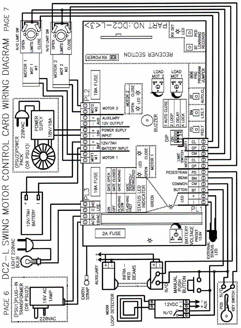
2 CONTROL CARD INSTALLATION PROCEDURE (Refer to DC2-L SWING MOTOR CONTROL CARD WIRING DIAGRAM pages 6 & 7) -2- A. LIMIT SWITCH CONNECTION normal open limit (N/O) MASTER MOTOR (M1) : OPENING limit to PL1 Pin OP (M1) COMMON to Pin CM, CLOSING limit to Pin CL (M1). SLAVE MOTOR (M2): OPENING limit to PL1 Pin OP (M2), COMMON to Pin CM, CLOSING limit to Pin CL (M2). B. 12V DC MOTOR CONNECTION MASTER MOTOR 1: to PL2, 2 Pins M1 (MOT) SLAVE MOTOR 2: to PL2, 2 Pins M2 (MOT) C. PEDESTRIAN OPENING CONNECTION Normal open SPRING RELEASE KEY SWITCH, KEYPAD OR INTERCOM button connected to PL1 Pin PD and common to Pin CM. D. INFRA RED BEAM CONNECTION The infra red beam prevents the gate hitting an object in its path. When the gate is closing, breaking the beam will make the gate stop, then open. The beam (N/O) contacts: to PL1 Pin BM and Pin CM 12V DC supply for beams from PL2 Pin + (AUX) and Pin (AUX) E. MAGNETIC FREE EXIT LOOP DETECTOR CONNECTION- The loop detector can be used by vehicles to trigger the gate to open for complexes. The control card must be set on condominium mode. The loop (N/O) contacts: to PL1 Pin BT and Pin CM 12V DC supply for loop from PL2 Pin + (AUX) and Pin (AUX). F. GATE STATUS INDICATION There is an on board (STAT) GREEN STATUS LED and a connection for an external LED to the house. LED anode to PL1 Pin + (LED) and Pin (LED) GREEN LED INDICATOR ON OFF FLASHING SLOW FLASHING FAST GATE OPEN GATE CLOSED GATE MOVING GATE STOPPED/OBSTRUCTED
3 -3- G.1 COURTESY LIGHT CONNECTION The courtesy light relay will switch on automatically, timed from when the gate is opened and for a period after the gate is closed. The relay (N/O) contacts are used to switch the neutral for the 220V AC mains to the light bulb. Relay (N/O) contacts from PL3 Pin NO (LITE) and PL3 Pin C (LITE) CAUTION LIVE MAINS!! Make sure mains are off before connections are made to control card G.2 LOCK RELAY CONNECTION (DIP 4 ON) Instead of the relay operating a light, with dip switch 4 on it will control a electric lock which will release momentary before and after the motors turn. The relay (N/O) contacts are used to switch power to the lock H. BATTERY CONNECTION 12V/7 AHR BATTERY +POS to PL2 Pin + (BAT) and NEG to Pin (BAT) NB!! When card is powered up for the first time, buzzer will beep a few times. Thereafter, if it beeps while opening both gates, the battery is flat. I. PLUG IN TRANSFORMER CONNECTION Used in DOMESTIC APPLICATIONS, then DO NOT USE POWER PACK. The transformer (PSU1) is plugged into nearest powerpoint and 16VAC is run in conduit to the gate motor. 16VAC/1AMP supply connected to PL3 Pin (16VAC) and Pin (16VAC) J. CHANGING RADIO RECEIVER If another make of radio receiver needs to be installed, the built-in receiver can be deactivated by removing the RX power jumper. The new receiver pulse N/O contact must be connected to PL1 Pin BT and Pin CM Power for the receiver from PL2 Pin+ (AUX) and Pin (AUX) K. POWER PACK CONNECTIONS Used in high usage gates such as complexes. Mains need to be supplied to the gate motor Mains 220V AC must be connected to the 220V AC POWERPACK INPUT (PSU2). The POWER PACK OUTPUT 18VDC/18AMP is connected to positive PL2 Pin + (18V) and negative Pin (18V). CAUTION! High DC current and mains voltage. Be sure connections are correct BEFORE switching on.
4 -4- CONTROL CARD PROGRAMMING AND SET-UP NB! Both gates must be set up on limits and CLOSED before programming can be done DIP SWITCH SETTING (DP) 1 ON = AUTOCLOSE 2 ON = FREE EXIT/CONDOMINIUM MODE 3 ON = ONE GATE DELAYED ON OPENING 4 ON = LIGHT RELAY BECOMES LOCK RELAY 1. AUTOCLOSE Both gates must be on CLOSED LIMITS. Switch dipswitch (DP) (AUTO CL) ON. Place (PRG) jumper across two pins: buzzer will beep twice. Press and hold (BT-AUT.CL) button for required AUTO CLOSE TIME, buzzer will beep every second. When time reached release (BT-AUT.CL) button, buzzer will give one long beep plus one short beep. Remove (PRG) jumper. (To remove AUTOCLOSE: switch dipswitch 1 OFF) NB! Autoclose should only be used with an infra-red beam for safety, so the gate does not autoclose onto an object unsupervised. 2. CURRENT LOAD ADJUSTMENT FOR MASTER & SLAVE MOTORS The current adjustment is for setting the sensitivity of the obstruction sensing. When a gate senses an obstruction on closing, both gates will stop and automatically open. When a gate senses an obstruction on opening, both gates will stop and stay triggered by button or remote. Turn the LOAD POT (LOAD MOT1) master and (LOAD MOT2) slave clockwise, to increase the force of gate before sensing obstruction. NB! It is not recommended to set the sensitivity too fine.
5 -5-3. CONDOMINIUM/FREE EXIT LOOP MODE Switch DIPSWITCH 2 (DP) (LOOP) ON. This mode is used for multiple user dwellings and its function is to prevent another user operating the gate while one user is in the process of driving through the gate. The gate can only be triggered to open by remote, button or free exit loop. NB! An infra-red beam must be used in this mode as autoclose is active. 4. RUN TIME Run time is fixed at 25 seconds. 5. PEDESTRIAN OPENING Both gates must be closed on CLOSED LIMITS. Place (PRG) jumper across two pins: buzzer will beep twice. Press and hold (PD-PED.T) button: Gate (MOT1) MASTER will OPEN, release (PD-PED.T) button at required opening distance, buzzer starts to beep for autoclose time, each beep = one second. When required autoclose time reached, press (PD-PED.T) button: gate will CLOSE onto close limit and buzzer will give one long beep. Remove (PRG) jumper. 6. DELAY TIME Both gates must be on CLOSED LIMITS Used for gates with overlap flap or where one gate opens wider than the other. Gates must be closed on limits. Switch DIPSWITCH 1 (DP) OFF (if autoclose is learnt) Switch DIPSWITCH 3 (DP) ON (Delay dipswitch) Press and hold (BT-AUT.CL) button for required DELAY TIME, buzzer will beep every second. When time reached, release (BT- AUT.CL) button: buzzer will give one long beep. Remove (PRG) jumper. (To remove delay time: switch dipswitch 3 OFF) 7. LIGHT RELAY ON/OFF TIME Both gates must be on CLOSED LIMITS Place (PRG) jumper across two pins: buzzer will beep twice. Press & hold (BM LITE.T) button for required ON time, buzzer will beep every second. When time reached, release (BM-LITE.T) button: buzzer will give one long beep. Remove (PRG) jumper.
6
7 -8-8. RECEIVER SETUP The on board learning receiver has 3 functions built in:gate OPENING, PEDESTRIAN OPENING AND LIGHT RELAY CONTROL A TX1 can control GATE OPENING, or TX2 can control GATE and PEDESTRIAN OPENING, or TX3 can control GATE, PEDESTRIAN and the THIRD RED BUTTON can control the LIGHT RELAY. Code a transmitter with a personal code 1 to 7, leave 8, 9 on 0. To learn the transmitter codes into the receiver: FOR BOTH GATE OPENING: Press and hold TX1 RED or TX2, TX3 BLUE OR GREEN BUTTON, then press control card (BT-RECEIVER LEARN) button (RX DET) LED will come on. FOR SINGLE PEDESTRIAN GATE OPENING: Press and hold anyone of the other buttons not used, then press control card (PED-RECEIVER LEARN) button (RX DET) LED will come on. THE LIGHT RELAY CONTROL :Press & hold any one of the other buttons not used, then press control card (BT & PED RECEIVER LEARN) button (RX DET) LED will come on.
8 -9- FAULT FINDING THE DC2L CONTROL CARD SYMPTOM CAUSE ACTION Gate does not operate when the button or transmitter is pressed, Control board battery flat. AC power light off. Reconnect transformer and allow battery to charge for 6 8 hours. For powerpack version reconnect mains. Gate does not operate when the button or transmitter is pressed even though the battery is fully charged. Gate does not operate when transmitter is pressed even though the coded detect LED on the control lights up. Gate motor control board beeps when button or transmitter is pressed. Gate swings a short distance then stops and beeps. Gate opens a short distance then stops. Gate opens but does not close after button or transmitter has been pressed. Gate opens but does not autoclose. Transmitter & control board receiver codes are not the same. Motor wires not connected to control card. Motor fuse blown. Control card faulty. Control board battery has gone completely flat +/-2 volts and then allowed to charge again. Control board locked up. Button input on control card is shorted out. Battery is going flat. (Battery versions only) Battery is going flat (Battery versions only) Gate motor load current control set is too sensitive. Pedestrian key permanently activated. Gate jammed open. Close limit jammed. Control card set to condominium. Autoclose not set. Gate motor beam input activated. Correct the code on either the receiver or transmitter. Connect motor wires. Replace fuse. Contact Supplier Press button on board to reset microprocessor or remove both 12V DC and 16V AC power for +/- 10 sec and reconnect. Remove short from button input, either from external button or intercom button. Allow battery to charge 2-3 hours. Allow battery to charge 2-3 hours. Disengage gate from motor and test that gate is running smoothly then adjust load control. Check pedestrian key and make sure the contact is open. Unjam or replace limit switch. Switch dipswitch 2 off. Switch dipswitch 1 on and maybe learn autoclose. Remove obstruction in front of the beam, or beam is incorrectly installed or faulty. Gate stopped on obstruction or open limit faulty. Gate will only autoclose from open limit. Remove obstruction or replace open limit. Gate opens then autocloses. Gate motor set up for autoclose. Switch dip sw 1 + sw 2 off
9 -10- Gate will not respond to the button or transmitter while opening. While closing, gate will stop and open after button or transmitter is pressed. Gate travels in the wrong direction when opening or closing but does not stop on limit switches. Gate travels in the right direction when opening or closing but does not stop on limit switches. Not enough range from remote control. Gate motor 12V, 6.5 amp hour battery seems to go flat quickly. (Battery versions only) One gate leaf opens before the other. Gate opens with the transmitter or button pressed. Gate motor set on free exit loop mode. Gate motor set on free exit loop mode. Motor & limit switch wires incorrect. Limit switch wired incorrectly or broken. Limit switch broken. Transmitter battery flat. Built in receiver interference from surrounding installation. Radio interference. Receiver on gate motor control card, low sensitivity. Excessive traffic through gate. Battery under or over charged. Frequent mains power failures. Over extended battery life. Too much other electrical equipment connected to motor s auxiliary supply. Delay opening has been setup. A neighbour has the same transmitter code. The button is picking up inductive interference. Switch dip sw 2 off. Switch dip sw 2 off. Change motor and limit switch wires around. Correct wiring or replace. Replace limit switch Replace transmitter battery. Mount ET-RX1L external receiver as high as possible on post. Remove card RX power jumper. Return transmitters and control card to change frequency. Make sure aerial is not bent down on control board. Consult supplier. Consult supplier. Consult electricity supplier. Replace battery. Connect separate power supply to other electrical equipment Switch dip sw 3 off. Change the code. Connect an ET-RELAY board interface to isolate the interference.
DTS 412/512/624 SLIDING GATE MOTOR INSTALLATION MANUAL
 DTS 412/512/624 SLIDING GATE MOTOR INSTALLATION MANUAL DTS SECURITY P.O.BOX 3399 EDENVALE 1610 TELEPHONE 086 1000 387 Base plate-mounting instructions Alberton 011 907 8846 Centurion 012 653 4434 Edenvale
DTS SLIDING GATE MOTOR INSTALLATION MANUAL. DTS 600 Elite with SL150 PCB DTS SECURITY P.O.BOX 3399 EDENVALE 1610 TELEPHONE
 DTS SLIDING GATE MOTOR INSTALLATION MANUAL DTS 600 Elite with SL150 PCB DTS SECURITY P.O.BOX 3399 Base plate-mounting EDENVALE instructions 1610 TELEPHONE 086 1000 387 Spartan +2711 392 5540 (H/O) Pretoria
Installer Instructions
 (400mm stroke length) Plus For dimensions of the 300mm model please contact us directly Installer Instructions 1 Page Table of contents Category Introduction 3 Safety obligations and general warnings 4
R3R5 quick setup guide ROTARY SWING GATE OPERATOR
 R3R5 quick setup guide TM TM ROTARY SWING GATE OPERATOR 1 REQUIRED TOOLS & EQUIPMENT Check that you have all the tools required. (IM page 1) 3 SITE CONSIDERATIONS Check for the safety and suitability of
UMPETHA U / Domestic sliding gate operator by ET SYSTEMS. USER GUIDE
 Domestic sliding gate operator by ET SYSTEMS. USER GUIDE 1 Table of contents Page Description 3 Safety obligations and general warnings M anual ov erride 3 How to mov e the gate by hand. Manual override
DTS SECURITY P.O.BOX 3399 EDENVALE 1610 Base plate-mounting instructions TELEPHONE
 DTS ECO 500 SLIDING GATE MOTOR INSTALLATION MANUAL DTS SECURITY P.O.BOX 3399 EDENVALE 1610 Base plate-mounting instructions TELEPHONE 086 1000 387 Spartan +2711 392 5540 (H/O) Pretoria +2712 361 5528 Alberton
Gate & Door Controller with LCD and Intelligent Technology
 2nd Edition Gate & Door Controller with LCD and Intelligent Technology 24Sv1 and 12Sv1 Motor Controllers Setup and Technical information for single motor controller for gates & doors Includes latest Intelligent
ET BLUE-ROLL Domestic type roll-up garage door operator. Installation manual Revision Oct
 ET BLUE-ROLL Domestic type roll-up garage door operator Installation manual Revision Oct.08.002 support@et.co.za Technical specifications may change without prior notice. All goods are subject to the standard
PAGE. 20. Connecting an intercom.
 PAGE C0NTENTS 2. Introduction. 2. Warnings. 2. Specifications. 3. General information. 3. Terms and definitions. 4. Installation. 5. Pedestal mount. 6. Pedestal mount inward swing. 7. Pedestal mount outward
INSTALLATION AND OWNERS MANUAL
 SLIDE GATE OPERATORS: COMPACT 300 COMPACT 500 SOLO CONDO CONDO AC/DC SWING GATE OPERATORS: DURASWING GARAGE DOOR OPERATORS: LAZER SECTIONAL LAZER ROLL UP LAZER VERTICAL ROLL UP LAZER TIP UP PROUD MANUFACTURERS
CB-9 CONTROL BOARD INSTRUCTION MANUAL
 CB-9 CONTROL BOARD INSTRUCTION MANUAL AUGUST 95 The CB-9 control board is designed to automate 1 or 2 A.T.A swing gate or sliding gate drive units. This instruction manual gives detailed instructions on
CB CONTROL BOARD INSTRUCTION MANUAL VERSION 1.03 DATE 30/10/2000
 CB-9 3.02 CONTROL BOARD INSTRUCTION MANUAL VERSION 1.03 DATE 30/10/2000 FIRMWARE VERSION 1.09 Thank you for choosing the CB-9 control system. We encourage you to read and understand this manual prior to
APOLLO Gate Operators, Inc.
 APOLLO Gate Operators, Inc. Model 3500ETL/3600ETL Commercial Swing Gate Operator INSTALLATION MANUAL 01/08 CONTENTS IMPORTANT SAFETY INSTRUCTIONS. 3 Applications... 4 Pre-Installation Checklist... 5 Parts
ET-500 AUTOMATIC SLIDE GATE MOTOR INSTALLER S MANUAL FOR ACDC500 & DC500 MODELS
 ET-500 AUTOMATIC SLIDE GATE MOTOR INSTALLER S MANUAL FOR ACDC500 & DC500 MODELS take control of your world REVISED DATE: May 2004 INDEX 1. WHAT S IN THE BOX A list of contents you will receive with this
The House of Gate Automation
 OPTIONAL EXTRA'S SOFT START / SOFT START This is provided as an optional extra and must be requested to fit to a new or old system. It provides an adjustable slow start and slow stop to prevent slambing
Single or Double 240VAC motor control for domestic and industrial gates and doors.
 COBO30 Double 240V Motor Drive Controller Features For 240Volt Motors Auto Closing Open Only Security Closing and Extended Lock Pulse (user selectable) Travel Timer Push Button Input Photo Cell Input Option
SKC400U SLIDING GATE OPENER OWNER S MANUAL
 SKC400U SLIDING GATE OPENER OWNER S MANUAL IMPORTANT SAFTEY INFORMATION Installing the SKC400U Gate Opener requires wiring of standard 110V electrical lines. This should only be performed by a trained
Roll Up Door Operator
 INSTRUCTIONS & OWNERS MANUAL Roll Up Door Operator 2 INDEX Preparation before installation 4. Terms and definitions 5. Pictures & names of parts 6. Mounting the weight bar 7. Installing the operator 7.
Instruction Manual for the. E-SL 450 Series
 Instruction Manual for the E-SL 450 Series Estate Slide Summary of Functions The Estate Slide is only to be used for vehicular Slide gates in a Class I setting. Class I: A vehicular gate opener (or system)
Index. COMPACT domestic gate operator
 COMPACT domestic gate operator Index Introduction. 3. General motor layout 4. General site layout 5. Terms and definitions. 6.. Site evaluation. 6. Gate evaluation 7. Removing the lid 8. Placing the gate
12V DC MOTORISED OPENER FOR SWING GATES Section Table of Contents Page
 12V DC MOTORISED OPENER FOR SWING GATES Section Table of Contents Page 1 Introduction 2 2 Warnings 4 3 Technical Specifications 5 4 Positioning 6 5 Wiring Diagram 7 6 Standard Installation Kit 8 7 Installation
HYPPOETL HYPPO DUALETL 12 VOLT DC Swing Gate Operator
 HYPPOETL HYPPO DUALETL 12 VOLT DC Swing Gate Operator Manufactured by NICE SpA INSTALLATION MANUAL 08/10 CONTENTS IMPORTANT SAFETY INSTRUCTIONS... 3 Applications...... 4 Pre-Installation Checklist... 5
 Access Blue Boom support@et.co.za 0860 109 238 G&C Electronics cc. T/A ET Systems 15 Nelson Rd, Observatory, Cape Town, South Africa www.et.co.za Technical specifications may change without prior notice.
GLM SERIES CONTROL Users Manual Rev:
 GLM SERIES CONTROL Users Manual Rev: 808062 Connecting Power Page 2 Motor Terminal Wiring Diagrams Page 3 Getting Started / Setup Page 4 1. Obstruction Detection Devices Page 4 2. Checking Power and Direction
CONTENTS INTRODUCTION
 CONTENTS INTRODUCTION 2 Lubrication 3 Physical dimensions 4 Technical specifications 5 STANDARD INSTALLATION KIT 6 WARNINGS 7 INSTALLATION OF THE UNIT 8 Initial preparations and mounting the base plate
Domestic sliding gate operator by ET SYSTEMS. Installer instructions
 Domestic sliding gate operator by ET SYSTEMS. Installer instructions 1 Table of contents Page Category Introduction 3 Safety obligations and general warnings 4 Identification of components 5 Technical
R3 and R5 user guide ROTARY SWING GATE OPERATOR
 R3 and R5 user guide TM TM ROTARY SWING GATE OPERATOR Table of Contents Company Profile................................................................... 3 Introduction.......................................................................
Sliding Gate Operator User's Manual
 Sliding Gate Operator User's Manual PY800AC/PY00AC. Products introduction Please read the instructions carefully before proceeding. MCU is supplied to control the gate operator. Keypad / single button
Sliding Gate Operator User's Manual
 Sliding Gate Operator User's Manual SL600AC. Products introduction Please read the instructions carefully before proceeding. MCU is supplied to control the gate operator. Keypad / single button interface.
Operators, Inc. Model 1550ETL Single Swing Gate Operator Model 1650ETL Dual Swing Gate Operator INSTALLATION MANUAL 04/07
 APOLLO Gate Operators, Inc. Model 1550ETL Single Swing Gate Operator Model 1650ETL Dual Swing Gate Operator INSTALLATION MANUAL 04/07 CONTENTS IMPORTANT SAFETY INSTRUCTIONS... 3 Applications... 4 Pre-Installation
ASSA ABLOY Series Power Operator Installation and Instruction ASSA Manual ABLOY ASSA ABLOY
 00 Series Power Operator Installation and Instruction ASSA Manual ABLOY Item No. Description Motor (00M) Cover (00COV) Control Inverter (00IN) Power Supply VDC (00PS) Track Assembly (0-) / Replacement
DKC400Y AC Sliding Gate Installation Manual. Sliding Gate Opener. Model: DKC400Y. Installation Manual WARNING
 Sliding Gate Opener Model: DKC400Y Installation Manual WARNING Read and thoroughly understand all instructions before installing or operating this automatic gate opener. Failure to do so may cause serious
ACSI MODEL 1406BB-04-AO POWER SUPPLY INSTALLATION INSTRUCTIONS
 II 1400-10 ACSI MODEL 1406BB-04-AO POWER SUPPLY INSTALLATION INSTRUCTIONS Features: Up to 1.95 Amps Load Capacity Class 2 Rated Outputs Overload, Over Voltage, and Short Circuit Protection Standby Battery
HIGH SPEED SLIDING GATE OPENER
 HIGH SPEED SLIDING GATE OPENER Model: is1200 + Elsema s Eclipse Control Card with GDS Operator USER MANUAL CONTENTS Section No: Page No: 1 Safety Precautions 3 2 Wiring Requirements 4 3 Installation details
Swing Gate Kits AUTOMATIC GATE KITS & ACCESSORIES SECURING GATES SINCE Control Cards. Accessories 2017 / Gate & Door Controls Catalogue
 Sliding Gate Kits 3G Gate Opener Swing Gate Kits AUTOMATIC GATE KITS & ACCESSORIES SECURING GATES SINCE 1978 Control Cards Accessories 2017 / 2018 Gate & Door Controls Catalogue Gate and Door Technology
E-SL 450BD Series INSTRUCTION MANUAL WARNING USER DRIVEN MANUAL*
 USER DRIVEN MANUAL* Any feedback, changes, or advice we are glad to hear it. Please contact us at support@estateswing.com WARNING Read all instructions before beginning installation or use of this gate
Sectional And Tilting Door Opener
 Sectional And Tilting Door Opener Installation Instructions and User Guide FS 600 FS 1000 FS 1200 600N 1000N 1200N FS 600-Speed FS 1000-Speed 600N 1000N S/N WARNING Please read the manual carefully before
DOMESTIC SLIDING GATE OPERATOR
 D Turbo Pocket mechanical installation guide TM DOMESTIC SLIDING GATE OPERATOR This guide is designed specifically for installers who are familiar with the installation of standard sliding gate motors,
INSTALLATION & OWNERS MANUAL
 PROUD MANUFACTURERS & SUPPLIERS OF: SLIDE GATE OPERATORS: COMPACT 500 SPRINT CONDO CONDO AC/DC SWING GATE OPERATORS: DURASWING GARAGE DOOR OPERATORS: LAZER SECTIONAL LAZER ROLL UP LAZER VERTICAL ROLL UP
INSTALLATION M ANUAL
 INSTALLATION MANUAL Table of Contents UL Listings Installing the Warning Sign / Precautions Methods of Installation / Compact Installation Mounting the Secondary Entrapment / Welding Gate Arn Mounting
DENISON HYDRAULICS Jupiter 500 Driver Card Series S
 Back to Content DENISON HYDRAULICS Jupiter 500 Driver Card Series S20-11712-0 Publ. 9-AM681 E-Mail: denison@denisonhydraulics.com Internet: http://www.denisonhydraulics.com SYSTEM FEATURES SYSTEM FEATURES
ASSA ABLOY Series Power Operator Installation and Instruction ASSA Manual ABLOY ASSA ABLOY
 0 Series Power Operator Installation and Instruction ASSA Manual ABLOY Item No. Description Motor (00M) Cover (00COV) Control Inverter (00IN) Power Supply VDC (00PS) / Replacement Motor Key (00KEY) Rod
RAMSET RAM
 www.ramsetinc.com TABLE OF CONTENTS Important Safety Requirements & Instructions...1 Responsibilities of Installers and Technicians...2 Important Safety Requirements by UL Standards...3 Classes of Vehicular
SB SWITCH CONTROL BOX
 Carson Manufacturing Co., Inc. 5451 North Rural Street Indianapolis, IN 462 Phone: (888) 577-6877 Fax: (317) 254-2667 www.carsonsirens.com SB-008-25 SWITCH CONTROL BOX INSTALLATION AND OPERATING INSTRUCTIONS
B100S - Super Swing. Instruction Manual. Document number: B100S-C Release: V4.0 Date: May 08,2009
 B00S - Super Swing Instruction Manual Document number: B00S-C Release: V4.0 Date: May 08,009 ! WARNING This control must be adjusted/serviced by a qualified person. The service technician must be familiar
APOLLO Gate Operators, Inc.
 APOLLO Gate Operators, Inc. Model BA12 12 VOLT DC BARRIER ARM OPERATOR INSTALLATION MANUAL 0707 CONTENTS IMPORTANT SAFETY INSTRUCTIONS... 3 Applications... 4 Pre-Installation Checklist... 5 Operator Installation...
AUTOMATIC CONTROL ROLLING DOOR OPENER
 AUTOMATIC CONTROL ROLLING DOOR OPENER INSTALLATION INSTRUCTION AUTOMATIC OBSTRUCT PHOTOELECTRIC BEAM ROLLING CODE SYSTEM AUTO CLOSE DOOR ANTI-THEFT SYSTEM INSTALLATION INSTRUCTION AND RDO OWNERS MANUAL
Model 1550 Single Swing Gate Model 1650 Dual Swing Gate
 Gate Operators, Inc. Model 1550 Single Swing Gate Model 1650 Dual Swing Gate Swing Gate Operator CONTENTS Safety Precautions... 2 Applications... 3 Pre-Installation Checklist... 4 Parts Identification...
TECHNICAL MANUAL AND ELECTRONICAL MODULE REGULATION VVVF-4 +
 TECHNICAL MANUAL AND ELECTRONICAL MODULE REGULATION VVVF-4 + 8 CABIN DOORS DESCRIPTION OF SWITCHES The unit may be programmed using the DIL switches on the front of the unit. If any change is made to any
RAMSET
 RAMSET TABLE OF CONTENTS Important Safety Requirements & Instructions...1 Responsibilities of Installers and Technicians...2 Important Safety Requirements by UL Standards...3 Classes of Vehicular Gate
FROG KIT. Installation Instructions for a Pair of gates... TECHNICAL HELPLINE THE FROG-P KIT CONSISTS OF:
 CAME UNITED KINGDOM LTD UNIT 3 ORCHARD PARK INDUSTRIAL ESTATE, TOWN STREET, SANDIACRE, NOTTINGHAM NG10 5BP TEL: 0115 921 0430 FAX: 0115 921 0431 TECHNICAL HELPLINE 0115 921 0430 INTERNET - www.cameuk.com
SWING GATE OPENERS 24V DC GEAR MOTOR
 SWING GATE OPENERS 24V DC GEAR MOTOR FOR RESIDENTIAL USER MANUAL Flashing Light Push Button Control box Gate 2 Gate 1 Index Warnings 2 5. Technical Characteristics 21 1. Product Description and Applications
CONTROL UNIT BIOS2. Manual for installation. Programmable Control board for wings gates.
 Programmable Control board for wings gates www.remotecontrolgates.co.uk Manual for installation Compatible from firmware version BIOS2BT02 CONTROL UNIT BIOS2 1. Introduzione The control unit BIOS2 is particularly
VC-4820 Programmable DC-DC Converter with Battery Charger function USER'S MANUAL
 1. INTRODUCTION VC-4820 Programmable DC-DC Converter with Battery Charger function USER'S MANUAL This MCU controlled Step Down DC-DC Converter has a digitally adjustable output in 0.2V increments. This
Installation and Maintenancee Manual
 Installation and Maintenancee Manual Commercial Boom Gate Operator Model: GDS BOOM 4 and 6 A.B.N. 62 059 806 405 Nov 2013 Section No: CONTENTS Page Number: 1 Safety Precautions 3 2 Specifications 4 3 Mechanical
LI-2B Installation Manual
 ARCO Pty. Ltd. LI-2B Intelligent Gate Controller Installation/Owners Manual Please do not commence installation until you have read this instruction book. Contents: Introduction Installation Options: Standard
CS-865RKE Series II REMOTE KEYLESS ENTRY SYSTEM
 INTRODUCTION: CS-865RKE Series II REMOTE KEYLESS ENTRY SYSTEM INSTALLATION & OPERATING INSTRUCTIONS CONGRATULATIONS on your choice of a Remote Keyless Entry System by Crimestopper Security Products Inc.
F ERNI K I T THE FERNI-S KIT CONSISTS OF:
 CAME UNITED KINGDOM LTD ORCHARD PARK INDUSTRIAL ESTATE TOWN STREET, SANDIACRE, NOTTINGHAM, NG10 5BP TEL: 0115 921 0430 FAX: 0115 921 0431 INTERNET - www.cameuk.com E-MAIL - enquiries@cameuk.com TECHNICAL
Sliding Gate Operator. User's Manual WARNING THIS PRODUCT MUST BE INSTALLED BY A QUALIFIED ELECTRICIAN
 Sliding Gate Operator User's Manual WARNING THIS PRODUCT MUST BE INSTALLED BY A QUALIFIED ELECTRICIAN BMG Imports Sliding Gate Opener MODEL No. LW550 Power rating: 220-240v AC 50Hz 550w Duty Close: 0-120
ELSEMA Single / Double Gate Controller, with Battery Charger, for 12V / 24V Motor, Enclosed, GATCOxxxCH
 GATCO12SCH, GATCO24SCH, GATCO12DCH, GATCO24DCH Single / Double Gate Controller, with Battery Charger, for 12V / 24V Motor Features 4 Versions: GATCO12SCH 12V Single motor GATCO24SCH 24V Single motor GATCO12DCH
APOLLO Gate Operators, Inc.
 APOLLO Gate Operators, Inc. Model 7200ETL Post Mounted Residential & Heavy Duty Commercial Slide Gate Operator INSTALLATION MANUAL 04/11 CONTENTS IMPORTANT SAFETY INSTRUCTIONS... 3 Applications... 4 Pre-Installation
Automatic Garage Door Operator
 Automatic Garage Door Operator support@et.co.za ET Systems (PTY) Ltd 15 Nelson Rd, Observatory, Cape Town, South Africa www.et.co.za Technical specifications may change without prior notice. All goods
RAM TABLE OF CONTENTS
 TABLE OF CONTENTS Important Safety Requirements & Instructions...1 Responsibilities of Installers and Technicians...2 Important Safety Requirements by UL Standards...3 Classes of Vehicular Gate Operators...4
Advanced Remote Vehicle Starting System
 INSTALLATION GUIDE 1600 Advanced Remote Vehicle Starting System 1600M AUTOMATIC AND MANUAL TRANSMISSION MODELS WWW.ULTRASTARTERS.COM See website for a full size printable version of this manual. WARNING!!
Installation and Maintenance Manual
 Installation and Maintenance Manual Swing Gate Operator Model HL410-21 & HL410L-21 2 Contents Contents Parts & Components 3 Specifications & Capacities 4 Safety Information 6 Installer 6 End User 7 General
ELSEMA 240VAC Slider Control Board, SLD
 SLD Slider Control Board ELSEMA Features For Single 240VAC Motor Built-in transformer, auto close, open only, security close & special security close Application Control an automatic door or gate with
Linear Actuator Swing Gate Operator Installation Manual Model # LA405-24
 Linear Actuator Swing Gate Operator Installation Manual Model # LA405-24 2 Contents Contents Product Information and Specs. 3 Mechanical 3 Electrical, Line Connections 3 Electrical, Control Connections
ARCHITECTURAL CONTROL SYSTEMS, INCORPORATED ST. LOUIS, MISSOURI
 II 1400-6 ARCHITECTURAL CONTROL SYSTEMS, INCORPORATED ST. LOUIS, MISSOURI ACSI 1426-04-AO ELECTRIC LATCH RETRACTION CONTROLLER INSTALLATION INSTRUCTIONS I.D. 1092, REV. C INSTALLATION For C-UL Listed applications,
INSTALLATION INSTRUCTIONS FOR Owner's Copy FILTERED AND REGULATED POWER SUPPLY VOLTS DC INPUT: Hz.
 103158 March 9, 2011 FOR INDOOR USE ONLY Detex Corporation, 302 Detex Drive, New Braunfels, Texas 78130-3045 (830)629-2900 / 1-800-729-3839 / Fax (830)620-6711 E-MAIL: detex@detex.com INTERNET: www.detex.com
SKC-500DC SLIDING GATE OPENER OWNER S MANUAL
 SKC-500DC SLIDING GATE OPENER OWNER S MANUAL OUTLINE 1. Safety Precautions 2. Features 3. Specifications 4. Necessary Tools 5. Site Preparation 6. Mechanical Installation 7. Electrical Installation 8.
5600 Series Power Operator Installation and Instruction Manual
 5600 Series Power Operator Installation and Instruction Manual 80-956-000-00 (08-) 5 ASSA ABLOY 6 Item No. Description Motor (5600M) Cover (5600COV) Control Inverter (5600IN) Power Supply VDC (5600PS)
Typical applications are the control of barriers/booms in the parking and access control environments.
 Barrier Logic Model - BL110B The BL110B is a barrier logic unit which has been developed to control barriers using magnetic motors with ease of installation. The BL110B accepts inputs from card readers
REVISED ATM72 Auto Transfer Module
 Capricorn Controls DA01ATM1-1 Data & Application Note Page 1 of 8 REVISED - - - ATM72 Auto Transfer Module Genset Controls - Timers - Monitors - Trips - Battery Charging - Spares & Accessories - Custom
AgriWheel Single Gate Kit Low Voltage & Solar. Installation & Operating Instructions
 AgriWheel Single Gate Kit Low Voltage & Solar Installation & Operating Instructions Thank you for purchasing you AgriWheel system. Please remove the lids from both the machine and control box and remove
PY600AC Sliding Gate Opener User Manual
 PY600AC Sliding Gate Opener User Manual 2017 Dear users, Thank you for choosing this product. Please read the manual carefully before assembling and using it. Please do not leave out the manual if you
Installation and a Maintenancee Manual
 Installation and a Maintenancee Manual Commercial Sliding Gate Operator MODEL: GDS 450 LV (WITH ELSEMA ECLIPSE OPERATING SYSTEM) MADE IN AUSTRALIA FROM AUSTRALIAN & QUALITY IMPORTED COMPONENTS A B N July
535T Window Automation System
 535T Window Automation System Installation Guide NOTE: This product is intended for installation by a professional installer only! Any attempt to install this product by any person other than a trained
EDR G /03
 1 Important safety instructions for operation It is vital for the safety of persons to follow all instructions. Save these instructions. WARNING Do not allow children to play with door controls. Keep remote
CONTROL BOX. Wiring the control box into the vehicle. +12V
 CONTROL BOX Once the display panel is in place, mount the control box within the connecting cable's distance (approximately 3 feet) and secure to the underside of the dashboard. This case does not have
Installing the gate post bracket with the cardboard arm template
 ......... Installing the gate post bracket with the cardboard arm template... Installing gate posts brackets and arms for Push-to-Open or Pull-to-Open gates... Connection of Power Source 240Vac or Solar...
Table of Contents. General Safety Preparation for Installation Parts List Optional Accessories Part List... 5
 REV 12a Table of Contents General Safety....... 2 Preparation for Installation....... 3 Parts List....... 4 Optional Accessories Part List...... 5 Technical Specifications & Feature...... 5 Installation
INSTALLER S MANUAL AUTOMATIC GARAGE DOOR OPENER
 take control of your world INSTALLER S MANUAL AUTOMATIC GARAGE DOOR OPENER REVISED DATE: March 2004 INDEX 1. WHAT S IN THE BOX A list of contents you will receive with this product and technical specifications
Setup and Programming Manual
 Microprocessor and Handy Terminal Setup and Programming Manual Versions U04 to U19 for Sliding Door Systems P/N 159000 Rev 7-2-07 The manufacturer, NABCO Entrances, Inc. suggests that this manual be given
USERS GUIDE LO-21U LOCKOUT RELAY
 USERS GUIDE LO-21U LOCKOUT RELAY PRODUCT DESCRIPTION The LO-21U (PN: 10LO21U) is a micro-processed lock out module designed to operate on swing door applications with BEA s Bodyguard or DK-12 overhead
MM1 Installation Instructions
 MM1 Installation Instructions PROFESSIONAL INSTALLATION STRONGLY RECOMMENDED Installation Precautions: Roll down window to avoid locking keys in vehicle during installation Avoid mounting components or
INSTRUCTION INVERTER COMPACT FOR SLIDING GATES /R0 10/11/2017
 INSTRUCTI INVERTER COMPACT FOR SLIDING GATES 6-1622616 /R0 10/11/2017 2 / 20 3 / 20 1. INTRO The control unit INVERTER COMPACT is integrated in the motor KALOS XL. It is a device suitable for operating
DLKEK3HN INSTALLATION INSTRUCTIONS
 DLKEK3HN INDEX: INSTALLATION INSTRUCTIONS WIRING INSTRUCTIONS... PG 2-5 LED STATUS INDICATOR... PG 6 VALET/OVERRIDE BUTTON... PG 6 SHOCK SENSOR... PG 7 PROGRAMMABLE JUMPER-PINS... PG 7 PROGRAMMING REMOTE
MD10. Engine Controller. Installation and User Manual for the MD10 Engine Controller. Full Version
 MD10 Engine Controller Installation and User Manual for the MD10 Engine Controller. Full Version File: MartinMD10rev1.4.doc May 16, 2002 2 READ MANUAL BEFORE INSTALLING UNIT Receipt of shipment and warranty
Owner s Manual. Series 6300 Vehicular Swing Gate Operators
 Owner s Manual Series 6300 Vehicular Swing Gate Operators DoorKing, Inc. 120 Glasgow Avenue Inglewood, California 90301 U.S.A. Phone: 310-645-0023 Fax: 310-641-1586 www.doorking.com P/N 6300-065 REV E,
Instruction Manual for the. E-SC 1600 / E-SC 1602 Series
 Instruction Manual for the E-SC 1600 / E-SC 1602 Series WARNING - Read all instructions before beginning installation or use of this gate opener. This operator exerts a high level of force. Exercise caution
SECEUROGLIDE ROLLER GARAGE DOORS, SECEUROSHIELD, SECEUROSCREEN & SECEUROVISION ROLLER SHUTTERS CONTENTS
 Operating & Maintenance Instructions SECEUROGLIDE ROLLER GARAGE DOORS, July 2007 Issue 4 SECEUROSHIELD, SECEUROSCREEN & SECEUROVISION ROLLER SHUTTERS CONTENTS Page 1. General Instructions 2 2. Operating
WARRANTY WILL BE VOID If These Steps are Not Performed Before Installing The Control STEPS TO PERFORM BEFORE CONTROL INSTALLATION
 Curtis 1268-5411 This sheet is provided to aid in the installation of your remanufactured CURTIS controller. Upon installation, you may encounter problems that may, or may not, be due to a faulty controller.
Uninterruptible Power System
 USER'S MANUAL Emergency Backup Power Supply For Use With Computer Loads Only Power Surge/Noise Protection Intelligent Auto-Shutdown Software Internet Line Protection Cost Efficiency UPS 1 st Edition Uninterruptible
User s Manual. Automatic Switch-Mode Battery Charger
 User s Manual Automatic Switch-Mode Battery Charger IMPORTANT Read, understand, and follow these safety rules and operating instructions before using this battery charger. Only authorized and trained service
MEGA 462 REMOTE CONTROL AUTO ALARM SYSTEM INSTALLATION & OPERATION INSTRUCTIONS WIRING DIAGRAM. White. H1 5 Pin White. H6 2 Pin White.
 MEGA 462 REMOTE CONTROL AUTO ALARM SYSTEM INSTALLATION & OPERATION INSTRUCTIONS WIRING DIAGRAM H7/1 Green : (-) 200mA Pulse H7 3 Pin H7/3 Blue : (-) 200mA Unlock White LED Indicator Valet Switch H6 2 Pin
INSTALLATION MANUAL. This unit is designed for professional installation only and must be installed by an authorized Silencer dealer.
 INSTALLATION MANUAL SL- 3 3-Channel Security with Keyless Entry System This unit is designed for professional installation only and must be installed by an authorized Silencer dealer. For Warranty information:
Installing the gate post bracket with the cardboard arm template
 ......... Installing the gate post bracket with the cardboard arm template... Installing gate posts brackets and arms for Push-to-Open or Pull-to-Open gates... Connection of Power Source 240Vac or Solar...
Owner s Manual. Models 6050 and 6100 Vehicular Swing Gate Operators
 Owner s Manual Models 6050 and 6100 Vehicular Swing Gate Operators DoorKing, Inc. 120 Glasgow Avenue Inglewood, California 90301 U.S.A. Phone: 310-645-0023 Fax: 310-641-1586 www.doorking.com P/N 6050-065
DESIGNED FOR RESIDENTIAL APPLICATION KIT PL600/PL1000 SLIDING GATE OPENERS
 SLIDING GATE OPENER DESIGNED FOR RESIDENTIAL APPLICATION KIT PL600/PL1000 SLIDING GATE OPENERS The strongest solution for sliding gates PL600/PL1000 electro-mechanical sliding gate openers are designed
C802/C802D/C802TD/C820 Alternators Troubleshooting Guide
 C802/C802D/C802TD/C820 Alternators Troubleshooting Guide Hazard Definitions These terms are used to bring attention to presence of hazards of various risk levels or to important information concerning