Commutation Assembly and Adjustment Details Make the Difference Gary Lozowski Morgan Advanced Materials June 13, MEMSA Technical Symposium
|
|
|
- Evan Sullivan
- 5 years ago
- Views:
Transcription


1 Commutation Assembly and Adjustment Details Make the Difference Gary Lozowski Morgan Advanced Materials June 13, MEMSA Technical Symposium
2 COMMUTATION Commutation is the Reversal of Armature Current in the Armature Coils The following slides and comments will assume that the electrical design of the motor or generator is sound and a proven design.
3 COMMUTATION Commutation is the Reversal of Armature Current in the Armature Coils Good Commutation or SPARKLESS operation occurs when the parts are machined, assembled and adjusted correctly Sparking at the brushes occurs when parts are machined, assembled or adjusted incorrectly. Rough comms., weak springs, sandblasted BH or excessive vibration can also cause sparking
4 Main Purpose of a Brush To conduct electrical current from it, to a rotating Commutator or Slip Ring In the case of a DC Motor with a Commutator, it needs to conduct current to each and every commutator segment It needs to have intimate contact with the comm. segments to conduct current without arcing ( Arcing or sparking is current going through air )
5 Good Commutation is a team effort of the brush, commutator, brush holder and springs. It takes proper mechanical adjustment of these parts. Uniform air gap settings of the poles is also very important. Electrical settings like neutral and interpole strength also need to be correct for good operation of DC Motors & Generators.

 Rotational")
6 Commutation / Brush Demands Since The Beginning (e.g KW) Rotational Speed 1200 RPM - 20 Rev per Second!
7 Commutation / Brush Demands Since The Beginning (e.g KW) Bars Pass each brush at a rate of 3000 commutator bars per second! And the brushes need to contact every one of them to prevent arcing

8 Commutation / Brush Demands Since The Beginning (e.g KW) Sliding Speed 70 Miles per Hour 6,123 ft / minute Equivalent to 14,000 RPM of a typical car engine piston

9 Commutation / Brush Demands Since The Beginning (e.g KW) Revolutions per day - 1,728,000 ( 630,720,000 / year )

10 Commutation / Brush Demands Since The Beginning (e.g KW) Distance a brush slides in 6 months- 305,000 miles ( only 274,000 miles at 90% running time )
11 Commutation / Brush Demands Since The Beginning (e.g KW) Commutation Cycles (current reversals) 120 per second (6 per revolution)

12 Commutation / Brush Demands Since The Beginning (e.g KW) Current Switched Per Commutation Cycle 733 Amperes at Rated Current 1466 Amperes at Stall Current
13 Commutation / Brush Demands Since The Beginning (e.g KW) Time to Switch the Current seconds 0.84 milli seconds
14 Most Draglines in The USA Have Been Doing This For More Than 25 Years No Small Accomplishment!!
15 What Has Been Done Since The Machines Were New? Larger Buckets Added - Higher RMS Loads - More Heat - Switching Higher Currents Greater % of the Time
16 What Has Been Done Since The Machines Were New? Static Motor Field Exciters Higher Rope Speeds Increased RMS Current Faster Average Motor Speeds

17 What Has Been Done Since The Machines Were New? New Controls - Faster Response - Higher Rate Of Current Change (di / dt)
18 What Has Been Done Since The Machines Were New? - Many Draglines Have Greatly Increased Productivity Since New - Often With Less Maintenance People - And More Pressure for Less Down Time for Maintenance
19 A1 A2 F1 F2 S S N NZ Approx 30% CZ NZ CZ = Commutating Zone N - N NZ = Neutral Zone N S S
20 A1 A2 F1 F2 S S N - N N N S S
21 Straightened-out Connection View Frame Stator Armature Coils S N S N Main Pole Main Pole Main Pole S Commutator Segments A1 Brush Rotation Brush A2
22 Straightened-out Connection View Frame Stator Armature Coils S N S N Main Pole Main Pole Main Pole S Commutator Segments Brush Rotation Brush A2 A1
23 Linear Commutation of a Coil That is Correctly Compensated Graph of Current A I Time - 200A t Armature Coils 200A 200A 200A 200A 200A 200A 200A 200A Rotation Commutator Segments Brush 400A V = - K d I d t This is the Voltage generated as one armature coil is commutated.
24 Machine Adjustments 1. Brush Position ( neutral ) 2. Commutating Field Strength
25 Factory Method vs Field Method
26 Excavator MG Set


27 Methods to Set Electrical Neutral DC Kick AC Null Reversability (Speed & Voltage) Black Band Brush Potential Pencil Volt Neutral AC Curve Method

28 Black Band Set Up B.B. Gen Comm Field Field ARM Load
29 Buck Amps Boost Amps Buck Boost Curve Load Amps (%)
30 Buck Boost Curve Buck Amps Boost Amps 0 X X Band Center on Boost Side (Weak) x No sparking in black area, sparking outside black area x x Band Center x Corrective Action Remove nonmagnetic shims, add magnetic shims x x Load Amps (%)
31 Buck Boost Curve Buck Amps Boost Amps 0 X X x Corrective Action Remove magnetic shims, add non magnetic shims x 150 Band Center x Band Center on Buck Side (Strong) Sparking with no buck or boost x x Load Amps (%) x

32 Buck Amps Boost Amps Buck Boost Curve Near perfect black band centered at all loads X x x x X x x x Load Amps (%)
33 Adjustable.015 Commutating Pole Shim Fixed.125 Thick Commutating Pole Shim GE uses non- Magnetic comm Pole bolts


34 Commutating Pole & Shims Magnet Frame Commutating Pole Thin Steel Thin Aluminum 1/8 Inch Aluminum 1/8 Inch Steel Order of shims is very important!

35 Brush Spacing F A B A = B = C = D = E = F = Max. Spacing Diff. = E D C Target is.030 On Westinghouse Equipment Max. Spacing diff =.050 on GE equip.
36 Brush Arm Spacing Example A F B A = 8.90 B = 8.96 C = 9.02 D = 8.94 E = 9.01 F = 8.85 E D This will take some work to get all 6 measurements within.050 C Max. Spacing Diff. =.170 Target is.050 On GE
37 Brush Arm
38 Brush Spacing Clearance hole Commutator
39 Brush Holder Height
40
41 BRUSH Brush Holder Spacing BRUSH BRUSH HOLDER This gap between brush holder and commutator is usually between.070 and.093 for most industrial motors. Only on rather small or very large motors is the recommended gap beyond this range. This gap is not always adjustable on newer motor designs. Readjusting this gap should only be necessary after turning or stoning a substantial amount off the commutator or slip ring diameter. Slip ring motors typically have a.125 maximum gap. Too large of a brush holder setting is unstable and can promote a friction chatter condition.
42 Brush Holder Alignment Brush Holder alignment OK, exactly perpendicular to the slip ring surface or commutator surface Commutator or slip ring Rotation
43 Brush Holder alignment, not the best, but 1 or 2 degrees trailing is OK Commutator or slip ring Rotation
44 Brush Holder alignment needs adjustment. This is called leading or stubbing and can cause fast wear or friction chatter. Just 1 or 2 degrees makes a big difference. Commutator or slip ring Rotation
45 Pole Tip Spacing Frame A B Difference Between A and B is 1/8 Maximum
46 Uneven And Tapered Airgaps Pole Frame Armature Airgap Pole Frame Airgaps should be equal within.015
47 Airgap Taper Gauge
48 Airgap Measurement ( Equal within.015 )

49 All This Mechanical & Electrical Symmetry Was Important When The Machines Were New With The Upgrades and Productivity Improvements, it is Even MORE SO!!

50 Circulating currents within single wafer Brush I A Load Amps V R = i c x R A + V CD + i c x R B + V CD R B V CD V CD i c = V R - 2 V CD R A + R B R A V R i c i c Becomes less as R B increases Use high resistivity grade brush for difficult to commutate machines.

51 Reducing circulating currents with more wafers I A Load Amps V R = i c x R A + V CD + i c x R B +V CD + i c x R w R B V CD V CD R A V R i c R W i c = V R - 2 V CD R A + R B + R W i c Becomes less as R B increases Use a 2 or 3 wafer brush construction for difficult to commutate machines.

52 Commutator Repair Indicators Situation Runout ( TIR ) Bar to Bar Variance Undercut Depth NEW Less than.0015 Less than or more IN SERVICE Less than.003 Less than or more NEEDS REPAIR More than.003 More than or less
53 Radial Scale ( +/- 2.0 Mils) 2.0 Profiler MAS - Commutator - Radial Plot Brush Path Brushes Commutator Recording Plot Rec# Recording start (Actual) Size TIR Max BTB Mean BTB Std dev Suspect Hi Mica Remark Brush Path Mar 2003 ( 8:48:43 am) (209) 209 Bars 1.18 mil : : These brushes have an easy job of conducting current to each Commutator segment with 1.18 mils TIR.
54 Radial Scale ( +/- 2.0 Mils) Profiler MAS - Commutator - Radial Plot Track Recording Plot Rec# Recording start (Actual) Size TIR Max BTB Mean BTB Std dev Suspect Hi Mica Remark Track Mar 2002 ( 4:06:18 pm) (211) 211 Bars 3.39 mil : : These brushes will have a harder job trying to contact each Commutator segment with 3.39 mils TIR &.44 Max. BTB
55 Radial Scale ( +/- 2.0 Mils) Profiler MAS - Commutator - Radial Plot Brush Path Recording Plot Rec# Recording start (Actual) Size TIR Max BTB Mean BTB Std dev Suspect Hi Mica Remark Brush Path Jun 2003 ( 7:47:42 am) (213) 213 Bars 3.94 mil : : These brushes have an impossible task of trying to contact each commutator segment with 3.94 mils TIR & 2.32 MBTB
56 Radial Scale ( +/- 2.0 Mils) Profiler MAS - Commutator - Radial Plot 1 * 200 * 20 Brush Path * * * * 140 * * Recording Plot Rec# Recording start (Actual) Size TIR Max BTB Mean BTB Std dev Suspect Hi Mica Remark Brush Path Jun 2003 ( 7:47:42 am) (213) 213 Bars 3.94 mil : : You can hear brush clatter and see sparking when comm. TIR is excessive. Poor brush life is also realized.
57
58 Advanced Pitch Bar Burning

59 Off Center Commutator Re-surfacing

60 These brushes are from a motor with a very rough comm. Brush wear is different since TIR of each brush path is different.
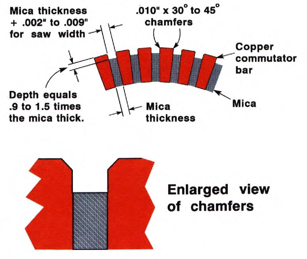
61 Commutator Undercutting
62 How Much Brush Pressure? The proper amount of brush pressure against the commutator or slip ring depends on the application and/or the brush grade. To calculate the brush pressure; you need to know or measure the spring force and the brush thickness and width. Brush T x W = the cross sectional area. Brushes that contact the commutator at an angle do have more contact area that the product of their T x W, but it is usually not a significant difference so the easier to calculate cross sectional area is used. Recommended Brush PSI Range Application 3.5 to 6 General Industrial Motors 3 to 8 Fractional HP Motors 5 to 10 Traction Motors 3 to 4 Slip Rings Low Speed, Graphite Grade 2 to 2.75 Slip Rings High Speed, Graphite Grade 3 to 5 Metal Graphite Grades
63 Wear Rate Total Brush Wear Optimum Range Brush Pressure ( PSI )
64 Do not sandblast springs or brush holders! Solvent clean

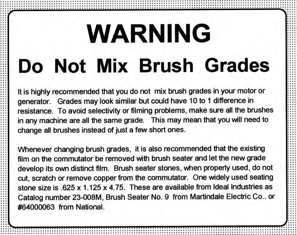
65 Do Not mix brush grades or brush springs
66
67 Airborne Contaminants 5% Carbon Graphite from the brush 15-20% Carbon Brush Grains of Moisture Copper Oxide 75% Copper Commutator Commutator Film Makeup
68 Electrographitic Brush Materials and treatments Treatment can lubricate ( reduce friction ) Treatment increases Mechanical Strength Some Treatments Improve Commutation which Lowers Temperature And Increases Life Treatment help brushes survive harsh environments
69 Contaminants Gear Lubricants Vapors or mist can contribute to copper drag, insulation degradation and brush wear

70 Blower Inlet Grease splash drawn into Motor and on commutator

71 Copper Drag

72 Thank you for your attention Questions?
Carbon Brush Performance on Slip Rings
 Carbon Brush Performance on Slip Rings Richard D. Hall Morgan AM&T Roland P. Roberge Morgan AM&T Gary Lozowski Morgan AM&T Mining Electrical Maintenance and Safety Association September 9, 2010 Clearwater,
The Effect of DC Machine Adjustment on Loop Unbalance
 The Effect of DC Machine Adjustment on Loop Unbalance WMEA, Edmonton, Alberta, Canada June 11-13, 13, 2008 Rich Hall Morgan AM&T Jim Shackelford Peabody Energy Technical Contributor Jason Conrad GE Canada
ECEg439:-Electrical Machine II
 ECEg439:-Electrical Machine II 2.2 Main Structural Elements of DC Machine Construction of DC Machines A DC machine consists of two main parts 1. Stationary Part (Stator):-It is designed mainly for producing
Technical Developments in the Measurement of Commutator Profiles. Carbone of America. WMEA Tucson AZ. Roy Douglas Technical Manager
 Carbone of America Technical Developments in the Measurement of Commutator Profiles WMEA Tucson AZ. Roy Douglas Technical Manager Content 2 1. Tools and Methods of Measuring Commutator Profiles (9) 2.
UNIT 2. INTRODUCTION TO DC GENERATOR (Part 1) OBJECTIVES. General Objective
 OBJECTIVES. General Objective") DC GENERATOR (Part 1) E2063/ Unit 2/ 1 UNIT 2 INTRODUCTION TO DC GENERATOR (Part 1) OBJECTIVES General Objective : To apply the basic principle of DC generator, construction principle and types of DC generator.
DC GENERATOR (Part 1) E2063/ Unit 2/ 1 UNIT 2 INTRODUCTION TO DC GENERATOR (Part 1) OBJECTIVES General Objective : To apply the basic principle of DC generator, construction principle and types of DC generator.
INTRODUCTION Principle
 DC Generators INTRODUCTION A generator is a machine that converts mechanical energy into electrical energy by using the principle of magnetic induction. Principle Whenever a conductor is moved within a
Historical Development
 TOPIC 3 DC MACHINES DC Machines 2 Historical Development Direct current (DC) motor is one of the first machines devised to convert electrical power into mechanical power. Its origin can be traced to the
Carbon Brushes A Comprehensive Guide, for Industrial and Railway Technology
 8900 West Tower Avenue Milwaukee, WI 53224 800.962.4851 Fax 800.365.3113 www.helwigcp.com Carbon Brushes A Comprehensive Guide, for Industrial and Railway Technology Specifications Installation Troubleshooting
TOOLS & DEVICES FOR MAINTENANCE OF ELECTRICAL MACHINES
 PREVENTION TOOLS & DEVICES FOR MAINTENANCE OF ELECTRICAL MACHINES Preventive maintenance of slip rings and commutators MAINTENANCE TOOLS & MEASURING DEVICES ECONOMY SECURITY Regular controls reduce the
DC MOTOR MAINTENANCE ALL ELECTRIC LIFT TRUCKS PART NO SRM 294
 DC MOTOR MAINTENANCE ALL ELECTRIC LIFT TRUCKS PART NO. 897076 620 SRM 294 SAFETY PRECAUTIONS MAINTENANCE AND REPAIR When lifting parts or assemblies, make sure all slings, chains, or cables are correctly
Application Information
 Moog Components Group manufactures a comprehensive line of brush-type and brushless motors, as well as brushless controllers. The purpose of this document is to provide a guide for the selection and application
STARTER - HITACHI Isuzu Trooper II DESCRIPTION TESTING STARTER PERFORMANCE TESTS Starters HITACHI. Isuzu
 STARTER - HITACHI 1986 Trooper II 1984 Starters HITACHI DESCRIPTION Starter is a conventional 12-volt, 4-pole brush-type motor, with direct or reduction gear drive. The starter-mounted solenoid shifts
TRADE ENGINEERING. Solutions for Success. Products for the Mining Industry. Slip Ring Units
 TRADE ENGINEERING We are dedicated to successfully applying our skills and knowledge to some of the mining industry's most daunting challenges. We have the ability to engineer components under very diverse
STARTING SYSTEM LOCATION INDEX [LF]
![STARTING SYSTEM LOCATION INDEX [LF]](/thumbs/75/72592935.jpg "STARTING SYSTEM LOCATION INDEX [LF]") 1. Remove the battery cover. 2. Disconnect the negative battery cable. (See BATTERY REMOVAL/INSTALLATION [LF].) 3. Remove the side cover. (LH) 2007 Mazda MX-5 Miata Sport 2007 ENGINE Starting System -
1. Remove the battery cover. 2. Disconnect the negative battery cable. (See BATTERY REMOVAL/INSTALLATION [LF].) 3. Remove the side cover. (LH) 2007 Mazda MX-5 Miata Sport 2007 ENGINE Starting System -
 1 of 16 1/10/2015 7:25 AM STARTER MOTOR 2009 Hyundai Accent 1.6L Eng GS REQUESTED INFORMATION DISASSEMBLY 1. Disconnect the M-terminal (A) on the magnet switch assembly (B). Fig 1: Identifying M-Terminal
STARTER Mitsubishi Montero DESCRIPTION BENCH TESTING STARTER NO-LOAD TEST ELECTRICAL Mitsubishi Starters. Montero
 STARTER 1993 Mitsubishi Montero 1993 ELECTRICAL Mitsubishi Starters Montero DESCRIPTION The starter is a conventional 12-volt, 4-pole brush-type motor, with gear reduction drive. The starter-mounted solenoid
Basic Motor Theory. Introduction
 Basic Motor Theory Introduction It has been said that if the Ancient Romans, with their advanced civilization and knowledge of the sciences, had been able to develop a steam motor, the course of history
1991 Mazda MX-5 Miata. STARTER - DIRECT DRIVE ELECTRICAL Mazda Starters - Direct Drive ELECTRICAL Mazda Starters - Direct Drive
 DESCRIPTION STARTER - DIRECT DRIVE 1990-92 ELECTRICAL Mazda Starters - Direct Drive Nippondenso direct drive starter is a conventional 12-volt, 4-pole, brush-type starter. The integral solenoid is attached
DESCRIPTION & OPERATION
 STARTER - REDUCTION GEAR 1997 STARTING & CHARGING SYSTEMS Mazda - Starters - Reduction Gear DESCRIPTION & OPERATION Reduction gear starter is a conventional 12-volt, 4-pole, brush-type starter. The integral
Renown Electric s Guide to Carbon Brushes for Motors & Generators
 Renown Electric s Guide to Carbon Brushes for Motors & Generators Table Of Contents Introduction: Carbon Brush Definition and Operating Parameters...3 The 5 Main Carbon Brush Grades...6 Installing and
INFORMATION. covering use of Ammeter and Voltmeter ON and 1915 Model Six-54 Electrical System
 INFORMATION covering use of Ammeter and Voltmeter ON- 1914 and 1915 Model Six-54 Electrical System Hudson Motor Car Company Detroit, Michigan, IX S. A USE OF AMMETER ON 1914 AND 1915 MODEL SIX-54 With
STARTING/CHARGING SYSTEMS Brought to you by Eris Studios NOT FOR RESALE
 STARTING/CHARGING SYSTEMS General Description 1. General Description A: SPECIFICATION Vehicle model Starter Generator Item Specification Type Reduction type Model 428000-5760 Manufacturer DENSO Voltage
Seals Stretch Running Friction Friction Break-Out Friction. Build With The Best!
 squeeze, min. = 0.0035 with adverse tolerance build-up. If the O-ring is made in a compound that will shrink in the fluid, the minimum possible squeeze under adverse conditions then must be at least.076
SERVICING SPECIFICATIONS (1) ENGINE BODY
 ENGINE BODY") SERVICING SPECIFICATIONS (1) ENGINE BODY (1/14) Lubricating oil capacity Oil pan depth 124 mm (4.88 in.) 7.0 L 1.85 U.S.gals. 1.54 lmp.gals. 9.5 L 2.51 U.S.gals. 2.09 lmp.gals. Oil pan depth 90 mm (3.54
SERVICING SPECIFICATIONS (1) ENGINE BODY (1/14) Lubricating oil capacity Oil pan depth 124 mm (4.88 in.) 7.0 L 1.85 U.S.gals. 1.54 lmp.gals. 9.5 L 2.51 U.S.gals. 2.09 lmp.gals. Oil pan depth 90 mm (3.54
Carbon Brush & Holder Technical Handbook
 Carbon Brush & Holder Technical Handbook ENGINEERING Contents 2. What is a Carbon Brush? 4. Bedding In 5. Types of Brush Holders 5. Fitting Brushes & Holders 6. Checking spring pressure 7. Springs 9. Commutators
CHAPTER 6 INTRODUCTION TO MOTORS AND GENERATORS
 CHAPTER 6 INTRODUCTION TO MOTORS AND GENERATORS Objective Describe the necessary conditions for motor and generator operation. Calculate the force on a conductor carrying current in the presence of the
1997 Mazda MX-5 Miata. STARTER - DIRECT DRIVE 1997 STARTING & CHARGING SYSTEMS Mazda - Starters - Direct Drive
 STARTER - DIRECT DRIVE 1997 STARTING & CHARGING SYSTEMS Mazda - Starters - Direct Drive DESCRIPTION & OPERATION Direct drive starter is a conventional 12-volt, 4-pole, brush-type starter. The integral
Therefore, it is the general practice to test the tooth contact and backlash with a tester. Figure 19-5 shows the ideal contact for a worm gear mesh.
 19. Surface Contact Of Worm And Worm Gear There is no specific Japanese standard concerning worm gearing, except for some specifications regarding surface contact in JIS B 1741. Therefore, it is the general
Figure 1: Forces Are Equal When Both Their Magnitudes and Directions Are the Same
 Moving and Maneuvering 1 Cornerstone Electronics Technology and Robotics III (Notes primarily from Underwater Robotics Science Design and Fabrication, an excellent book for the design, fabrication, and
1994 Mazda MX-5 Miata. STARTER - DIRECT DRIVE 1994 ELECTRICAL Mazda Starter - Direct Drive
 DESCRIPTION STARTER - DIRECT DRIVE 1994 ELECTRICAL Mazda Starter - Direct Drive Nippondenso direct drive starter is a conventional 12-volt, 4-pole, brush-type starter. The integral solenoid is attached
SECTION 9 CRANKING SYSTEM CONTENTS
 SECTION 9 CRANKING SYSTEM CONTENTS 9-1. 9-2. 9-3. 9-4. 9-5. 9-6. 9-7. 9-8. GENERAL DESCRIPTION.,...,..., 9-2 SPECIFICATIONS.......................................... 9-4 LUBRICATION 9-5 REMOVAL AND INSTALLATION...
SERVICING SPECIFICATIONS (1) ENGINE BODY
 ENGINE BODY") SERVICING SPECIFICATIONS (1) ENGINE BODY Lubricating oil capacity Oil pan depth 110 mm (4.33 in.) 5.7 L 1.5 U.S.gals (1/14) Oil pan depth 125 mm (4.92 in.) 5.1 L 1.3 U.S.gals Oil pan depth 130 mm (5.12
SERVICING SPECIFICATIONS (1) ENGINE BODY Lubricating oil capacity Oil pan depth 110 mm (4.33 in.) 5.7 L 1.5 U.S.gals (1/14) Oil pan depth 125 mm (4.92 in.) 5.1 L 1.3 U.S.gals Oil pan depth 130 mm (5.12
DC Series Motors by Thomas E. Kissell Industrial Electronics, Second Edition, Prentice Hall PTR
 Site Help Search NI Developer Zone DC Series Motors by Thomas E. Kissell Industrial Electronics, Second Edition, Prentice Hall PTR Back to Document Table of Contents: Series Motor Diagram Series Motor
Institute of Technology, Nirma University B. Tech. Sem. V: Electrical Engineering 2EE305: ELECTRICAL MACHINES II. Handout: AC Commutator Motors
 Institute of Technology, Nirma University B. Tech. Sem. V: Electrical Engineering 2EE305: ELECTRICAL MACHINES II Handout: AC Commutator Motors Prepared by: Prof. T. H. Panchal Learning Objective: Introduction
INTRODUCTION GENERAL GUIDELINES ATTACHING THE DRIVE PARTS
 INTRODUCTION Kretzschmar DC motors are of substantialy designed and manufactured to high standards. These motors will work satisfactorily for many years as long as they are maintained following the instructions.
AGN Unbalanced Loads
 Application Guidance Notes: Technical Information from Cummins Generator Technologies AGN 017 - Unbalanced Loads There will inevitably be some applications where a Generating Set is supplying power to
Introduction: Electromagnetism:
 This model of both an AC and DC electric motor is easy to assemble and disassemble. The model can also be used to demonstrate both permanent and electromagnetic motors. Everything comes packed in its own
DC Motor Instruction Manual
 DC Motor Instruction Manual Contents Receiving Environment Wire Gauge Size DC Motor Electrical Connections Thermostat Connections Blower Motor Electrical Connections Air Filter Running the motor Commutator
1994 Mazda MX-5 Miata. STARTER - REDUCTION GEAR 1994 ELECTRICAL Mazda Starter - Reduction Gear
 DESCRIPTION STARTER - REDUCTION GEAR 1994 ELECTRICAL Mazda Starter - Reduction Gear The Nippondenso reduction gear starter is a conventional 12-volt, 4-pole, brush-type starter. The integral solenoid is
Just what is an alternator?
 Just what is an alternator? An alternator is the device used to produce the electricity the car needs to run and to keep the battery charged. The battery is the heart of your electrical system. But you
GEN 5.0 Generator Service Manual
 GEN 5.0 Generator Service Manual IMPORTANT: Read all safety precautions and instructions carefully before operating equipment. Refer to operating instruction of equipment that this engine powers. Ensure
FIBER BRUSHES: The Maintenance-Free Wind Turbine Slip Ring Contact Material
 FIBER BRUSHES: The Maintenance-Free Wind Turbine Slip Ring Contact Material By: Glenn Dorsey, PE Document Number 203 Slip Ring Product Line Manager SUMMARY Fiber brush technology allows the design of slip
ECEg439:-Electrical Machine II
 ECEg439:-Electrical Machine II 2.1.General Arrangement of DC Machine Objecties To instill an understanding of the underlying electromagnetic effects permitting electric machine operation and introduce
1950 Pacemaker. Specifications & Adjustments
 Specifications & Adjustments Specifications & Adjustments ENGINE: Valve Arrangement Bore and Stroke Piston Displacement Maximum Torque Horsepower Actual Taxable Compression Ratio: Cast Iron Head (Std.)
VALIADIS S.A. HELLENIC MOTORS
 HELLENIC MOTORS Instruction for Operation and Maintenance of KDC Series Medium DC Motors ATHENS : 18, Gr. Labraki Str., 141 23 Likovrisi Tel : +30210-2817217, Fax : +30210-2814277 THESSALONIKI : INDUSTRIAL
Chapter 22: Electric motors and electromagnetic induction
 Chapter 22: Electric motors and electromagnetic induction The motor effect movement from electricity When a current is passed through a wire placed in a magnetic field a force is produced which acts on
ELEN 236 DC Motors 1 DC Motors
 ELEN 236 DC Motors 1 DC Motors Pictures source: http://hyperphysics.phy-astr.gsu.edu/hbase/magnetic/mothow.html#c1 1 2 3 Some DC Motor Terms: 1. rotor: The movable part of the DC motor 2. armature: The
Synchronous Generators I. EE 340 Spring 2011
 Synchronous Generators I EE 340 Spring 2011 Construction of synchronous machines In a synchronous generator, a DC current is applied to the rotor winding producing a rotor magnetic field. The rotor is
LECTURE 27 SERVO VALVES FREQUENTLY ASKED QUESTIONS
 LECTURE 27 SERVO VALVES FREQUENTLY ASKED QUESTIONS 1. Define a servo valve Servo valve is a programmable orifice. Servo valve is an automatic device for controlling large amount of power by means of very
Service Bulletin Brake Disc Refinishing Guidelines (Supersedes , dated June 2, 2003) October 28, 2003
 October 28, 2003") Service Bulletin 00-037 Applies To: ALL Models October 28, 2003 Brake Disc Refinishing Guidelines (Supersedes 00-037, dated June 2, 2003) American Honda does not allow replacement of brake discs under
Service Bulletin 00-037 Applies To: ALL Models October 28, 2003 Brake Disc Refinishing Guidelines (Supersedes 00-037, dated June 2, 2003) American Honda does not allow replacement of brake discs under
Question 2: Around the bar magnet draw its magnetic fields. Answer:
 Chapter 13: Magnetic Effects of Electric Current Question 1: What is the reason behind the compass needle is deflected when it is brought close to the bar magnet? Compass needles work as a small bar magnet;
SSC-JE STAFF SELECTION COMMISSION ELECTRICAL ENGINEERING STUDY MATERIAL ELECTRICAL MACHINES
 1 SSC-JE STAFF SELECTION COMMISSION ELECTRICAL ENGINEERING STUDY MATERIAL 28-B/7, Jia Sarai, Near IIT, Hauz Khas, New Delhi-110016. Ph. 011-26514888. www.engineersinstitute.com 2 CONTENT 1. : DC MACHINE,
Mechatronics Chapter 10 Actuators 10-3
 MEMS1049 Mechatronics Chapter 10 Actuators 10-3 Electric Motor DC Motor DC Motor DC Motor DC Motor DC Motor Motor terminology Motor field current interaction Motor commutator It consists of a ring of
CHAPTER THREE DC MOTOR OVERVIEW AND MATHEMATICAL MODEL
 CHAPTER THREE DC MOTOR OVERVIEW AND MATHEMATICAL MODEL 3.1 Introduction Almost every mechanical movement that we see around us is accomplished by an electric motor. Electric machines are a means of converting
1GR-FE STARTING STARTER (for 4WD) DISASSEMBLY
 DISASSEMBLY") 14 1GR-FE ARTING ARTER (for 4WD) DISASSEMBLY 1. REMOVE ARTER YOKE ASSEMBLY (a) Remove the nut, then disconnect the lead wire from terminal C. Remove the 2 through bolts. (c) Pull the starter yoke and the
14 1GR-FE ARTING ARTER (for 4WD) DISASSEMBLY 1. REMOVE ARTER YOKE ASSEMBLY (a) Remove the nut, then disconnect the lead wire from terminal C. Remove the 2 through bolts. (c) Pull the starter yoke and the
COMPARING SLOTTED vs. SLOTLESS BRUSHLESS DC MOTORS
 COMPARING SLOTTED vs. SLOTLESS Authored By: Engineering Team Members Pittman Motors Slotless brushless DC motors represent a unique and compelling subset of motors within the larger category of brushless
Hydraulic Pump and Track Motor for Hydrostatic Transmission
 KYB TECHNICAL REVIEW No. 55 OCT. 2017 Product Introduction Hydraulic Pump and Track Motor for Hydrostatic Transmission INADA Takanori, MIURA Takuya, MATSUZAKA Keita 1 Introduction 2 Hydraulic Pumps There
Synchronous Generators I. Spring 2013
 Synchronous Generators I Spring 2013 Construction of synchronous machines In a synchronous generator, a DC current is applied to the rotor winding producing a rotor magnetic field. The rotor is then turned
DESIGN OF DC MACHINE
 DESIGN OF DC MACHINE 1 OUTPUT EQUATION P a = power developed by armature in kw P = rating of machine in kw E = generated emf, volts; V = terminal voltage, volts p = number of poles; I a = armaure current,
Application Note : Comparative Motor Technologies
 Application Note : Comparative Motor Technologies Air Motor and Cylinders Air Actuators use compressed air to move a piston for linear motion or turn a turbine for rotary motion. Responsiveness, speed
FARADAY S LAW ELECTROMAGNETIC INDUCTION
 FARADAY S LAW ELECTROMAGNETIC INDUCTION magnetic flux density, magnetic field strength, -field, magnetic induction [tesla T] magnetic flux [weber Wb or T.m 2 ] A area [m 2 ] battery back t T f angle between
The Effect of Spring Pressure on Carbon Brush Wear Rate
 The Effect of Spring Pressure on Carbon Brush Wear Rate By Jeff D. Koenitzer, P.E. Milwaukee, Wisconsin, USA Preface 2008 For decades there was extensive testing of countless different carbon brush contact
ENGINE ELECTRICAL Click on the applicable bookmark to selected the required model year
 ENGINE ELECTRICAL 16-1 ENGINE ELECTRICAL CONTENTS CHARGING SYSTEM................ 2 GENERAL INFORMATION................ 2 SERVICE SPECIFICATIONS.............. 3 SPECIAL TOOL......................... 3
2006 MINI Cooper S GENINFO Starting - Overview - MINI
 MINI STARTING SYSTEM * PLEASE READ THIS FIRST * 2002-07 GENINFO Starting - Overview - MINI For information on starter removal and installation, see the following articles. For Cooper, see STARTER WITH
Starting Systems & Traction Motor Systems. ATASA 5 th. ATASA 5 TH Study Guide Chapter 18 Pages Starting & Traction Motor Systems 62 Points
 ATASA 5 TH Study Guide Chapter 18 Pages 537 570 Starting & Traction Motor Systems 62 Points Please Read The Summary 1. Electric are used to start the engine & in hybrids are used to move the vehicle. Motors
PERFORMANCE THROUGH REVOLUTION
 PERFORMANCE THROUGH REVOLUTION Dynamatic has a complete range of gear pumps for both mobile and industrial market segments. Dynamatic developed these pumps in technical collaboration with DOWTY Hydraulic
Service Bulletin. Brake Disc Refinishing Guidelines (Supersedes , dated October 28, 2003, to update the information marked by the black bars)
") Service Bulletin 00-037 Applies To: ALL Models October 5, 2006 Brake Disc Refinishing Guidelines (Supersedes 00-037, dated October 28, 2003, to update the information marked by the black bars) American
Service Bulletin 00-037 Applies To: ALL Models October 5, 2006 Brake Disc Refinishing Guidelines (Supersedes 00-037, dated October 28, 2003, to update the information marked by the black bars) American
Universal APU2 Pumps AUTOMOTIVE PAINT SERIES
 Universal APU2 Pumps AUTOMOTIVE PAINT SERIES For more than half a century, Waukesha Cherry-Burrell has been a leader in the design, manufacturing and application of external circumferential, piston (ECP)
Chapter 7: DC Motors and Transmissions. 7.1: Basic Definitions and Concepts
 Chapter 7: DC Motors and Transmissions Electric motors are one of the most common types of actuators found in robotics. Using them effectively will allow your robot to take action based on the direction
Exercise 2-1. The Separately-Excited DC Motor N S EXERCISE OBJECTIVE DISCUSSION OUTLINE DISCUSSION. Simplified equivalent circuit of a dc motor
 Exercise 2-1 The Separately-Excited DC Motor EXERCISE OBJECTIVE When you have completed this exercise, you will be able to demonstrate the main operating characteristics of a separately-excited dc motor
Engine Electrical System
 Engine Electrical System 3 Foreword This manual has been prepared by experts and specialists of,engineering Department of Saipa Yadak Company to be used as a guide by the repairers of electrical systems.we
Chapter 3.2: Electric Motors
 Part I: Objective type questions and answers Chapter 3.2: Electric Motors 1. The synchronous speed of a motor with 6 poles and operating at 50 Hz frequency is. a) 1500 b) 1000 c) 3000 d) 750 2. The efficiency
Types of Adjustable Speed Drives
 Introduction Speed adjustment techniques have been used in transmitting mechanical power to machinery since the earliest use of powered machinery. Before electric motors were invented, mechanical speed
INSTRUCTIONS. Delco Systems
 INSTRUCTIONS FOR THE CARE OF 6-24 Delco Systems The Dayton Engineering Laboratories Co. Dayton, Ohio This is a description of the 6-24 volt system as applied to the following cars: 1912 Cadillac 1913 Cole
INSPECTION ST 13 2UZ-FE STARTING STARTER. Terminal 50. Terminal C. Battery. Disconnect Battery. Terminal C. Disconnect. Battery.
 2UZ-FE ARTING ARTER 13 INSPECTION 1. INSPECT ARTER ASSEMBLY NOTICE: These tests must be done within 3 to 5 seconds to avoid burning out the coil. (a) Do pull-in test. (1) Disconnect the field coil lead
INSTRUCTION MANUAL 272-5X5 ANALOG TRANSMITTER (210 SERIES FLOW METERS) 272-5X7 ANALOG TRANSMITTER (220/240 SERIES FLOW METERS)
 272-5X7 ANALOG TRANSMITTER (220/240 SERIES FLOW METERS)") INSTRUCTION MANUAL 272-5X5 ANALOG TRANSMITTER (210 SERIES FLOW METERS) 272-5X7 ANALOG TRANSMITTER (220/240 SERIES FLOW METERS) 272-5X8 BIDIRECTIONAL TRANSMITTER (210/240 SERIES FLOW METERS) TABLE OF CONTENTS
INSTRUCTION MANUAL 272-5X5 ANALOG TRANSMITTER (210 SERIES FLOW METERS) 272-5X7 ANALOG TRANSMITTER (220/240 SERIES FLOW METERS) 272-5X8 BIDIRECTIONAL TRANSMITTER (210/240 SERIES FLOW METERS) TABLE OF CONTENTS
CSDA Best Practice. Hi-Cycle Concrete Cutting Equipment. Effective Date: Oct 1, 2010 Revised Date:
 CSDA Best Practice Title: Hi-Cycle Concrete Cutting Equipment Issue No: CSDA-BP-010 : Oct 1, 2010 Revised : Introduction Hi-cycle/high frequency concrete cutting equipment has become more prevalent in
STARTER SYSTEM TESTING 5.6
 STARTER SYSTEM TESTING 5.6 ON-MOTORCYCLE TESTS b088x5x Starter Relay Test NOTE Starter relay test also applies to ignition and key switch relays.. See Figure 5-5. Locate starter relay. The relay is attached
20. Install and tighten the cap screws that hold the end frame and field frame together
 4006-30 19. Fill the oil reservoir in the bearing bore of the end frame with SAE 10 engine oil. Then put the the end frame on the armature shaft. Align the marks on the end frame and field frame and push
Focus on Sci. & Tech. Grasp Details
 Focus on Sci. & Tech. Grasp Details B Series Safety brake, adopts modular design and has multiple functions, which can facilitate super rapid response with its professionally designed for low power electromagnetic
STARTER SYSTEM TESTING 5.6
 STARTER SYSTEM TESTING 5.6 ON-MOTORCYCLE TESTS Starter Relay Test NOTE Starter relay test also applies to ignition and key switch relays.. See Figure 5-5. Locate starter relay. The relay is attached to
ATASA 5 th. ATASA 5 TH Study Guide Chapter 27 Pages Ignition Systems 68 Points. Please Read the Summary
 ATASA 5 TH Study Guide Chapter 27 Pages 810 835 68 Points Please Read the Summary Before We Begin Keeping in mind the Career Cluster of Transportation, Distribution & Logistics Ask yourself: What careers
CHAPTER 3 DESIGN OF THE LIMITED ANGLE BRUSHLESS TORQUE MOTOR
 33 CHAPTER 3 DESIGN OF THE LIMITED ANGLE BRUSHLESS TORQUE MOTOR 3.1 INTRODUCTION This chapter presents the design of frameless Limited Angle Brushless Torque motor. The armature is wound with toroidal
STARTING SYSTEM STARTING SYSTEM ST 1
 ST1 ST2 Troubleshooting TROUBLESHOOTING Problem Possible cause Remedy Page Engine will not crank Battery charge low Battery cables loose, corroded or worn Clutch start switch faulty (M/T) Neutral start
PARTS MANUAL EY35 / EY40 ENGINES. Models. PUB-EP5716A Rev. 04/00
 PARTS MANUAL Models EY35 / EY40 ENGINES PUB-EP5716A Rev. 04/00 940 Lively Blvd. Wood Dale, IL 60191 Phone: 630-350-8200 Fax: 630-350-8212 e-mail: sales@robinamerica.com www.robinamerica.com Copyright 2000
./#0#. 1"&." 1994 ELECTRICAL Suzuki of America Corp. - Starters. Swift
 !"" #$%!& '()!)((*(+,*)- 1994 ELECTRICAL Suzuki of America Corp. - Starters Swift Two types of starter motors are used, conventional and reduction gear. Both types of starters consist of yoke assembly,
2 Principles of d.c. machines
 2 Principles of d.c. machines D.C. machines are the electro mechanical energy converters which work from a d.c. source and generate mechanical power or convert mechanical power into a d.c. power. These
Lesson 5: Directional Control Valves
 : Directional Control Valves Basic Hydraulic Systems Hydraulic Fluids Hydraulic Tank Hydraulic Pumps and Motors Pressure Control Valves Directional Control Valves Flow Control Valves Cylinders : Directional
Electric motor testing
 Electric motor testing MOTOR (MODELS EJ4-4001 AND EJ8-4001A) 23 GENERAL INFORMATION The vehicle is equipped with a 48-volt DC, shunt-wound, reversible traction motor. The shunt-wound motor is designed
Motor Basics AGSM 325 Motors vs Engines
 Motor Basics AGSM 325 Motors vs Engines Motors convert electrical energy to mechanical energy. Engines convert chemical energy to mechanical energy. 1 Motors Advantages Low Initial Cost - $/Hp Simple &
Electrical Machines I Week 1: Overview, Construction and EMF equation
 Electrical Machines I Week 1: Overview, Construction and EMF equation Course Contents Definition of the magnetic terms, magnetic materials and the B-H curve. Magnetic circuits principles. Electromechanical
TEST ON DC MOTORS. EE 2092 Laboratory Practice III
 TEST ON DC MOTORS EE 2092 Laboratory Practice III CALCULATIONS Absorption Dynamometer Considering radius of pulley as r ; 2 r=11.618cm=0.11618m Armatur4e resistance (R a ) =4.1Ω, series field resistance
Universal computer aided design for electrical machines
 Neonode Inc From the SelectedWorks of Dr. Rozita Teymourzadeh, CEng. 2012 Universal computer aided design for electrical machines Aravind CV Grace I Rozita Teymourzadeh Rajkumar R Raj R, et al. Available
Air Cooled Engine Technology. Roth 9 th Ch 14 Elect. System Service Pages
 Roth 9 th Ch 14 Elect. System Service Pages 245 276 1. is the term used to describe periodic, preventative maintenance done to the ignition system of any engine. It may often times also include fuel system,
Technical Section. Thrust & Horsepower. Tool Assembly T-A & GEN2 T-A GEN3SYS
 Tool Assembly 1. Place the Drill Insert in the precision ground locating pocket on the Holder. 2. The drill insert should not be turned, rotated or twisted for locking purposes. The holder pocket and locating
SECTION 8 2 DO IT YOURSELF MAINTENANCE. Chassis
 DO IT YOURSELF MAINTENANCE Chassis SECTION 8 2 Checking the coolant level of the traction motor................ 184 Checking the radiator....................................... 185 Checking brake fluid........................................
SPH3U UNIVERSITY PHYSICS
 SPH3U UNIVERSITY PHYSICS ELECTRICITY & MAGNETISM L (P.599-604) The large-scale production of electrical energy that we have today is possible because of electromagnetic induction. The electric generator,
YDRAULIC ISC BRAKES VERVIEW
 YDRAULIC ISC BRAKES VERVIEW 02 03 03 04 05 07 11 14 16 Introduction The Lever The Brake Hose The Caliper Closed and Open Systems Braking Power Four-Piston Calipers Heat and Fade Care INTRODUCTION FACTORS
Electrical Machines -II
 Objective Type Questions: 1. Basically induction machine was invented by (a) Thomas Alva Edison (b) Fleming (c) Nikola Tesla (d) Michel Faraday Electrical Machines -II 2. What will be the amplitude and
ST- 1 STARTING SYSTEM. Page TROUBLESHOOTING... ST-2 STARTER... ST-3 STARTER RELAY... ST- 12 CLUTCH START SWITCH... ST-1 2
 ST- 1 STARTING SYSTEM Page TROUBLESHOOTING... ST-2 STARTER... ST-3 STARTER RELAY... ST- 12 CLUTCH START SWITCH... ST-1 2 ST-2 STARTING SYSTEM - Troubleshooting TROUBLESHOOTING Problem Possible cause Remedy