The Effect of DC Machine Adjustment on Loop Unbalance
|
|
|
- Maximillian Fisher
- 6 years ago
- Views:
Transcription


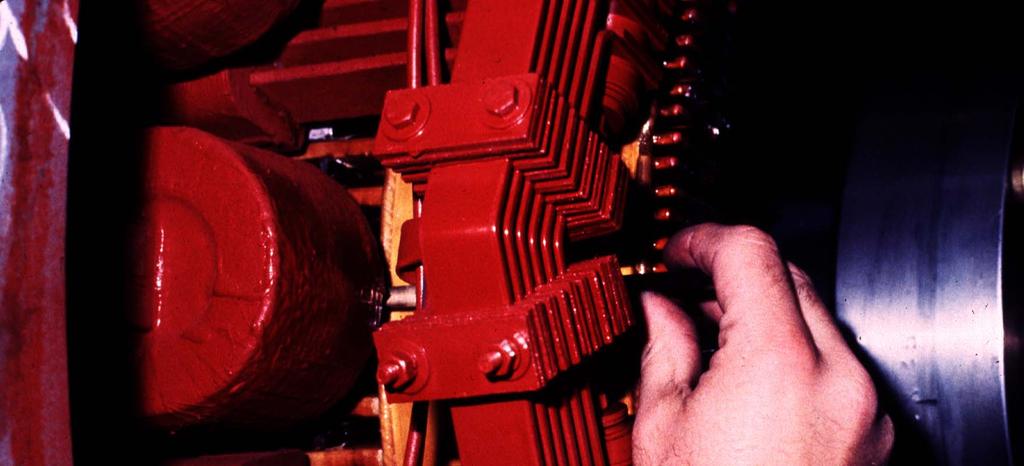
1 The Effect of DC Machine Adjustment on Loop Unbalance WMEA, Edmonton, Alberta, Canada June 11-13, 13, 2008 Rich Hall Morgan AM&T Jim Shackelford Peabody Energy

2 Technical Contributor Jason Conrad GE Canada Peterborough, Ontario, Canada
3 Dragline Generator Loops HG1 HG2 HM3 HM1 HM4 HM2 HG3 HG4 Loop 1 Loop 2
4 Dragline Loops Contain Direct Current Generators Direct Current Motors Ammeter Shunts Cables Connections
5 Dragline Generator Loops Design Benefits Multiple units in each loop average out some of the variation in individual generators and motors, cabling, etc. Multiple motors and generators average out the effect of temperature variations around the house Multiple loops give some degree of control of the machine if one loop is lost
6 Loop Balance Ideally, the loops behave exactly the same as each other under all conditions Visually, they would look like a well-choreographed synchronized swim team
7 Loop Balance cont. This means each generator behaves like every other generator Each motor behaves like every other motor Each loop s s cables and connections have the same resistance as each other loop
8 These loops act electrically in parallel If the generators in one loop produce more Voltage than the generators in other loops, that loop will draw more current If the motors in one loop try to run faster than the motors in other loops, they cannot because they are geared together, but that loop will draw more current
9 These loops act electrically in parallel If the resistances of the cables and connections are lower in one loop than the other loops, that loop will draw more current
10 So what?? Unbalanced loop currents may cause excessive torque in some loops, cause increased mechanical wear and take life out of couplings, gears, and structural parts of the machine Unbalanced loop currents may result in too little torque in some loops and reduce the productivity of the dragline
11 Other Problems Unbalanced loop currents may result in increased brush and commutator wear Unbalanced loop currents may result in flashovers Unbalanced loop currents may trip the loop overcurrent Unbalanced loop currents may cause the generator field overcurrent to trip
12 Bigger Problems!!! Unbalanced loop currents may result in overheating some generators or motors Badly unbalanced loop currents may cause the sync motors to pull out of synchronization, especially on weak power systems
13 Results This may cause damage to equipment, loss of productivity, increased downtime and increased repair costs Rule of thumb in the business loss insurance industry: the cost of the repair is 10% of the business loss
14 How much voltage does it take to drive rated current? The rating of a GE 1045 KW generator is 475 Volts and 2200 Amperes. It does not take 475 Volts to drive rated current in the loop, however.
15 How much voltage does it take to drive rated current? The answer about 20 Volts per generator!!!
16 How much voltage does it take to drive rated current? When the machines are in a motoring quadrant, the generators are generating an electro motive force (EMF), but the motors are also generating an electromotive force that opposes the generator EMF and it is called a counter EMF (CEMF).
17 How much voltage does it take to drive rated current? It is the sum of the generator Voltages minus the sum of the motor Voltages in the loop that drives loop current. This Voltage divided by the loop resistance gives the loop current.
18 Dragline Generator Loop _ + _ HG1 + Loop Current HM3 + HM1 _ + HG3 _ Loop 1
19 How much voltage does it take to drive rated current? The loop resistance is most easily determined at stall when the motors are not rotating or generating any CEMF. For a 1045 KW generator, about 40 Volts per generator drives stall current (2X rated current or 4400 Amperes). Loop Resistance = (40V + 40V 0V - 0V) = Ohm 4400 Amperes
20 How much voltage does it take to drive rated current? It does not take a large Voltage imbalance to drive a lot of current when you divide it by !!!
21 Standards for Loop Balance 5% of stall current at stall conditions 5% of stall current while running steady (even at peak power) 10% of stall current during transient load changes
22 How much voltage difference does it take to be at the recommended limits? 5% of 4400 Amperes = 220 Amperes V = IR = 220 Amperes x Ohms V = 3.9 Volts So a 4 Volt difference between loops is all it takes to be at 5% of stall current!
23 Four Quadrant Operation 2 + Volts 1 - Amps + Amps - Volts 3 4
24 First Quadrant Commutation Limits Loop 1 Armature Volts Unbalanced Loop Current Loop 2 Armature Amps
25 Loop Balance Loop 1 is the control loop and is inside the commutation limits, so it is OK. Loop 2 is the slave loop and is inside the commutation limits, so the equipment is OK. It is loafing, however, so the dragline is working at less than capacity.
26 First Quadrant Commutation Limits Loop 1 Armature Volts Unbalanced Loop Current Loop 2 Armature Amps
27 Loop Balance Loop 1 is the control loop and is inside the commutation limits, so it is OK. Loop 2 is the slave loop and is outside the commutation limits. This may lead to commutation distress, flashovers, excessive wear of couplings and gears, tripping of the machine, etc.
28 Assembling DC Machines To work properly together and to commutate well, machines must be built or rebuilt properly. Following are GE factory tolerances provided by GE Canada, Peterborough, Ontario.
29 Generators Pole centerline to pole centerline chord measured at both ends of machine minimum to maximum values must not differ by more than (3.2 mm)
30 Pole Tip Spacing Frame A B Difference Between A and B is 1/8 (3.2 mm) Maximum
31 Generators Brush Holder Assembly holders to be set to from commutator surface (1.8 to 2.0 mm) axial skew must not exceed one mica thickness over the length of the commutator
 Brush Box")
32 ( mm) Brush Box Height


33
34 Generators Circumferential brush spacing (paper tape on commutator) arcs measured from one brush toe to the next must be within 3/64 (0.047 or 1.2 mm) (MAXIMUM)
35
36 Brush Spacing F A B A = B = C = D = E = F = E Commutator Commutator D C Max. Spacing Diff. = Target is.030 On Westinghouse Equipment Max. Spacing diff =.050 on GE equip.
37 Generators Air Gaps all air gaps to be within +/ (0.18 mm) commutating pole air gaps may be different than main pole air gaps
38 Uneven And Tapered Air Gaps Pole Frame Armature Pole Frame


39 Air Gap Taper Gauge

40 Air Gap Measurement
41 Motors Pole centerline to pole centerline chord measured at both ends of machine minimum to maximum values must not differ by more than (3.2 mm)
42 Motors Brush Holder Assembly holders to be set to from commutator surface (1.8 to 2.0 mm) axial skew must not exceed one mica thickness over the length of the commutator
43 Motors Circumferential brush spacing (paper tape on commutator) arcs measured from one brush toe to the next must be within 3/64 (0.047 or 1.2 mm)
44 Motors Air Gaps all air gaps to be within +/ (0.18 mm) commutating pole air gaps may be different than main pole air gaps
45 g N N = Number of Turns g = Air Gap
46 e N i φ Flux φ α N x i
47 SATURATION CURVE Flux in φ Air Gap Air Air Gap Gap Region Region Iron Saturation Region N x I (Ampere F Turns)
48 Generated Volts Volts = E. M. F. = B x L xv where B = Flux Density ( φ / area) L= Length of the conductor V = Velocity of the conductor N V L I F e
49 Generator V α B x L x V V (EMF) α B α I Field
50 Speed V = B x L x V V α B x RPM Motor L RPM α Volts α Volts B Torque F α B x I A x L I Field Torque = Force x Radius Torque α B x I A r B ( Flux Density )
51 Motor V α B x L x V V α B x L x RPM V (CEMF) α B x RPM α I Field x RPM
52 Generator Data Sheet
53 No Load Saturation Curve Armature Volts MCF866B, 836 KW, 475 Volt, 1760 Ampere, 1200 RPM Field Amps
54 Load Curve 836 KW Gen. Armature Volts Arm. Amps Field Amps
55 Adjusting DC Machines - Factory Black Band Method See the paper NECP Tuning DC Motors and Generators Jun 07 on the WMEA web site wmea.net for other methods of tuning DC machines
56 Buck Boost Curve Buck Amps Boost Amps 0 X X X No Load Band Center on Buck Side (Strong) Corrective action shift brush rigging with rotation (motor) or against rotation (generator) Load Amps (%)
57 Buck Boost Curve X Buck Amps Boost Amps 0 X X No Load Band Center on Boost Side (Weak) Corrective action shift brush rigging against rotation (motor) or with rotation (generator) Load Amps (%)
58 Buck Boost Curve Buck Amps Boost Amps 0 X X Band Center on Boost Side (Weak) x x No sparking in black area, sparking outside black area x Band Center x Corrective Action Remove nonmagnetic shims, add magnetic shims x x Load Amps (%)
59 Buck Boost Curve Buck Amps Boost Amps 0 X X x Corrective Action Remove magnetic shims, add non magnetic shims x Band Center x Band Center on Buck Side (Strong) Sparking with no buck or boost x x Load Amps (%) x
60 Voltage or RPM Regulation Defined Decreased Voltage or RPM Regulation Volts or RPM Increased Voltage or RPM Regulation Armature Amps
61 Generator increased main pole air gap Saturation Curve Regulation Volts Volts Regulation decreases Before After Field Amps Armature Amps
62 Generator decreased main pole air gap Saturation Curve Regulation Volts Volts Regulation increases Before After Field Amps Armature Amps
63 Generator increased comm pole air gap or add nonmagnetic shims Saturation Curve Regulation Volts No Effect Volts Regulation increases Before After Field Amps Armature Amps
64 Generator decreased comm pole air gap or remove nonmagnetic shims Saturation Curve Regulation Volts No Effect Volts Regulation deceases Before After Field Amps Armature Amps
65 Generator brush shift with rotation Saturation Curve Regulation Volts No Effect Volts Regulation increases Before After Field Amps Armature Amps
66 Generator brush shift against rotation Saturation Curve Regulation Volts No Effect Volts Regulation decreases Before After Field Amps Armature Amps
67 Motor increased main pole air gap Saturation Curve Regulation Volts / RPM RPM Regulation increases Before After Field Amps Armature Amps
68 Motor decreased main pole air gap Saturation Curve Regulation Volts / RPM RPM Regulation decreases Before After Field Amps Armature Amps
69 Motor increased comm pole air gap or add nonmagnetic shims Saturation Curve Regulation Volts / RPM No Effect RPM Regulation increases Before After Field Amps Armature Amps
70 Motor decreased comm pole air gap or remove nonmagnetic shims Saturation Curve Regulation Volts / RPM No Effect RPM Regulation decreases Before After Field Amps Armature Amps
71 Motor Brush shift with rotation Saturation Curve Regulation Volts / RPM No Effect RPM Regulation increases Before After Field Amps Armature Amps
72 Motor Brush shift against rotation Saturation Curve Regulation Volts / RPM No Effect RPM Regulation decreases Before After Field Amps Armature Amps
73 Voltage Regulation Shunt Generator Low Voltage Regulation Volts Armature Amps
74 Voltage Regulation Shunt Generator Delta Volts Low Voltage Regulation Volts Delta Amps Armature Amps
75 Voltage Regulation Differential Compound Generator Higher Voltage Regulation Delta Volts Volts Delta Amps Armature Amps
76 Differentially Compound Generators Differentially compound generators limit loop current unbalances, as generators that are more heavily loaded (loop unbalance) will drop in voltage and shed some load. This helps, of course, but does not cure loop unbalance.
77 Machine Adjustments and Loop Balance Summary DC machines must be built to accepted tolerances of air gaps, brush spacing, brush box heights, pole spacing, comm pole bolt material, etc. to be as much alike as possible for the machines to commutate well and share load. Connections within the machines must be tight to minimize variation in excitation currents and loop resistance.
78 Machine Adjustments and Loop Balance Summary cont. When machines are disassembled and reassembled, it is important to keep track of shims, especially commutating pole shims. Both the thickness and order of shims are important! There is not an easy way to correct interpole shimming in the field, so care with the machines when working on them in shops is critical.
79 Machine Adjustments and Loop Balance Summary cont. There are many things that can contribute to commutation issues: rough commutators, symmetry of assembly, brush grades and construction, faulty machine components and electrical connections. Sometimes people try to fix machines by tuning them up with neutral adjustments. Remember this affects machine output and loop balance, and you cannot adjust out these underlying causes of commutation distress.
80 Field Process to Address Loop Unbalances Take Time versus: Drive Reference, Armature Volts and Amps, and Motor Field Current Make Stud to Stud Spacing Correct Set Neutral (on GE Generator 1/8 with Rotation) Adjust Generator Air Gaps to Ensure that the Sum of the Volts in Each Loop are Equal within 2.5 Volts per Generator in the Loop ( 4 Generators in the Loop 10 Volts) Trim Motor Fields As Necessary Adjust Motor Neutral As Last Resort (Should be at Neutral Not with or Against Rotation) If Possible Re-wire the Motion to Two Loops

81 Oversize Hole Use ½ Thin Wall Conduit to Center Stud on Yoke

82 Lot W Hoist Unbalance As Found 485 Amps 12.2%

83 Lot W Drag Unbalance As Found 988 Amps 24.9%

84 Lot W Hoist and Drag Unbalances As Left After Adjustments and Making Both Motions into Two Loops Hoist Unbalance 53 Amps 1.3% Drag Unbalance 95 Amps 2.4%

85 Key Drag Unbalance As Found 1800 Amps 50%

86 Key Drag Unbalance As Left 59 Amps 1.6%

87 Key Hoist Unbalance As Found 616 Amps -15.6%

88 Key Hoist Loop Unbalance As Left 139 Amps 3.5%
89 Related WMEA Papers available on wmea.net National Carbon Successful Brush Performance Jun 05 NECP Tuning DC Motors and Generators Jun 07
90 Reference Materials Loop Unbalance Guidelines GE Benchmark, January 1997, Steve Baade Loop Unbalance Guidelines GE Benchmark, April 1997, Steve Baade GE DC Machine Adjustments and Operating Characteristics
91 Reference Web Sites Morgan AM&T National Electrical Carbon GE Motors -
Commutation Assembly and Adjustment Details Make the Difference Gary Lozowski Morgan Advanced Materials June 13, MEMSA Technical Symposium
 Commutation Assembly and Adjustment Details Make the Difference Gary Lozowski Morgan Advanced Materials June 13, 2014 @ MEMSA Technical Symposium COMMUTATION Commutation is the Reversal of Armature Current
UNIT 2. INTRODUCTION TO DC GENERATOR (Part 1) OBJECTIVES. General Objective
 OBJECTIVES. General Objective") DC GENERATOR (Part 1) E2063/ Unit 2/ 1 UNIT 2 INTRODUCTION TO DC GENERATOR (Part 1) OBJECTIVES General Objective : To apply the basic principle of DC generator, construction principle and types of DC generator.
DC GENERATOR (Part 1) E2063/ Unit 2/ 1 UNIT 2 INTRODUCTION TO DC GENERATOR (Part 1) OBJECTIVES General Objective : To apply the basic principle of DC generator, construction principle and types of DC generator.
ELEN 236 DC Motors 1 DC Motors
 ELEN 236 DC Motors 1 DC Motors Pictures source: http://hyperphysics.phy-astr.gsu.edu/hbase/magnetic/mothow.html#c1 1 2 3 Some DC Motor Terms: 1. rotor: The movable part of the DC motor 2. armature: The
ECET 211 Electric Machines & Controls Lecture 5-1 Electric Motors. Lecture 5-1 Electric Motors
 ECET 211 Electric Machines & Controls Lecture 5-1 Electric Motors (1 of 4) Text Book: Chapter 5 Electric Motors, Electric Motors and Control Systems, by Frank D. Petruzella, published by McGraw Hill, 2015.
DC Series Motors by Thomas E. Kissell Industrial Electronics, Second Edition, Prentice Hall PTR
 Site Help Search NI Developer Zone DC Series Motors by Thomas E. Kissell Industrial Electronics, Second Edition, Prentice Hall PTR Back to Document Table of Contents: Series Motor Diagram Series Motor
 DC MOTORS DC Motors DC Motor is a Machine which converts Electrical energy into Mechanical energy. Dc motors are used in steel plants, paper mills, textile mills, cranes, printing presses, Electrical locomotives
2006 MINI Cooper S GENINFO Starting - Overview - MINI
 MINI STARTING SYSTEM * PLEASE READ THIS FIRST * 2002-07 GENINFO Starting - Overview - MINI For information on starter removal and installation, see the following articles. For Cooper, see STARTER WITH
Historical Development
 TOPIC 3 DC MACHINES DC Machines 2 Historical Development Direct current (DC) motor is one of the first machines devised to convert electrical power into mechanical power. Its origin can be traced to the
Principles of Electrical Engineering
 D.C GENERATORS Principle of operation of D.C machines, types of D.C Generators, e.m.f equation of D.C Generator, O.C.C of a D.C Shunt Generator, Load characteristics of D.C.Generators GENERATOR PRINCIPLE:
INTRODUCTION Principle
 DC Generators INTRODUCTION A generator is a machine that converts mechanical energy into electrical energy by using the principle of magnetic induction. Principle Whenever a conductor is moved within a
CHAPTER 6 INTRODUCTION TO MOTORS AND GENERATORS
 CHAPTER 6 INTRODUCTION TO MOTORS AND GENERATORS Objective Describe the necessary conditions for motor and generator operation. Calculate the force on a conductor carrying current in the presence of the
SYLLABUS. osmania university UNIT - I UNIT - II UNIT - III UNIT - IV CHAPTER - 1 : PRINCIPLES OF ELECTRO-MECHANICAL ENERGY CONVERSION CHAPTER - 2 :
 i UNIT - I SYLLABUS osmania university UNIT - II CHAPTER - 1 : PRINCIPLES OF ELECTRO-MECHANICAL ENERGY CONVERSION Energy in Magnetic System, Field Energy and Mechanical Force, Direction of Mechanical Force
Chapter 4 DC Machines
 Principles of Electric Machines and Power Electronics Chapter 4 DC Machines Third Edition P. C. Sen Chapter 4 DC machine Electric machine Type: rotating machine Applications: generator (electric source)
CHAPTER THREE DC MOTOR OVERVIEW AND MATHEMATICAL MODEL
 CHAPTER THREE DC MOTOR OVERVIEW AND MATHEMATICAL MODEL 3.1 Introduction Almost every mechanical movement that we see around us is accomplished by an electric motor. Electric machines are a means of converting
Module 9. DC Machines. Version 2 EE IIT, Kharagpur
 Module 9 DC Machines Lesson 38 D.C Generators Contents 38 D.C Generators (Lesson-38) 4 38.1 Goals of the lesson.. 4 38.2 Generator types & characteristics.... 4 38.2.1 Characteristics of a separately excited
AC Motors vs DC Motors. DC Motors. DC Motor Classification ... Prof. Dr. M. Zahurul Haq
 AC Motors vs DC Motors DC Motors Prof. Dr. M. Zahurul Haq http://teacher.buet.ac.bd/zahurul/ Department of Mechanical Engineering Bangladesh University of Engineering & Technology ME 6401: Advanced Mechatronics
Basic Motor Theory. Introduction
 Basic Motor Theory Introduction It has been said that if the Ancient Romans, with their advanced civilization and knowledge of the sciences, had been able to develop a steam motor, the course of history
PHY 152 (ELECTRICITY AND MAGNETISM)
") PHY 152 (ELECTRICITY AND MAGNETISM) ELECTRIC MOTORS (AC & DC) ELECTRIC GENERATORS (AC & DC) AIMS Students should be able to Describe the principle of magnetic induction as it applies to DC and AC generators.
PHY 152 (ELECTRICITY AND MAGNETISM) ELECTRIC MOTORS (AC & DC) ELECTRIC GENERATORS (AC & DC) AIMS Students should be able to Describe the principle of magnetic induction as it applies to DC and AC generators.
2014 ELECTRICAL TECHNOLOGY
 SET - 1 II B. Tech I Semester Regular Examinations, March 2014 ELECTRICAL TECHNOLOGY (Com. to ECE, EIE, BME) Time: 3 hours Max. Marks: 75 Answer any FIVE Questions All Questions carry Equal Marks ~~~~~~~~~~~~~~~~~~~~~~~~~~
FARADAY S LAW ELECTROMAGNETIC INDUCTION
 FARADAY S LAW ELECTROMAGNETIC INDUCTION magnetic flux density, magnetic field strength, -field, magnetic induction [tesla T] magnetic flux [weber Wb or T.m 2 ] A area [m 2 ] battery back t T f angle between
CURRENT ELECTRICITY - II
 SALIENT FEATURES Faraday s laws of electrolysis Magnetic effects of electricity Electro magnetic induction CURRENT ELECTRICITY - II FARADAY S LAWS OF ELECTROYLYSIS ELECTROLYSIS The process of decomposition
2 Principles of d.c. machines
 2 Principles of d.c. machines D.C. machines are the electro mechanical energy converters which work from a d.c. source and generate mechanical power or convert mechanical power into a d.c. power. These
Electrical Machines -II
 Objective Type Questions: 1. Basically induction machine was invented by (a) Thomas Alva Edison (b) Fleming (c) Nikola Tesla (d) Michel Faraday Electrical Machines -II 2. What will be the amplitude and
UNIT I D.C. MACHINES PART A. 3. What are factors on which hysteresis loss? It depends on magnetic flux density, frequency & volume of the material.
 EE6352-ELECTRICAL ENGINEERING AND INSTRUMENTATION UNIT I D.C. MACHINES PART A 1. What is prime mover? The basic source of mechanical power which drives the armature of the generator is called prime mover.
ECEg439:-Electrical Machine II
 ECEg439:-Electrical Machine II 2.2 Main Structural Elements of DC Machine Construction of DC Machines A DC machine consists of two main parts 1. Stationary Part (Stator):-It is designed mainly for producing
Carbon Brush Performance on Slip Rings
 Carbon Brush Performance on Slip Rings Richard D. Hall Morgan AM&T Roland P. Roberge Morgan AM&T Gary Lozowski Morgan AM&T Mining Electrical Maintenance and Safety Association September 9, 2010 Clearwater,
INSTITUTE OF AERONAUTICAL ENGINEERING Dundigal, Hyderabad
 INSTITUTE OF AERONAUTICAL ENGINEERING Dundigal, Hyderabad - 500 043 MECHANICAL ENGINEERING ASSIGNMENT Name : Electrical and Electronics Engineering Code : A40203 Class : II B. Tech I Semester Branch :
SSC-JE STAFF SELECTION COMMISSION ELECTRICAL ENGINEERING STUDY MATERIAL ELECTRICAL MACHINES
 1 SSC-JE STAFF SELECTION COMMISSION ELECTRICAL ENGINEERING STUDY MATERIAL 28-B/7, Jia Sarai, Near IIT, Hauz Khas, New Delhi-110016. Ph. 011-26514888. www.engineersinstitute.com 2 CONTENT 1. : DC MACHINE,
INDUCTANCE FM CHAPTER 6
 CHAPTER 6 INDUCTANCE INTRODUCTION The study of inductance is a very challenging but rewarding segment of electricity. It is challenging because at first it seems that new concepts are being introduced.
Electrical Machines-I (EE-241) For S.E (EE)
 For S.E (EE)") PRACTICAL WORK BOOK For Academic Session 2013 Electrical Machines-I (EE-241) For S.E (EE) Name: Roll Number: Class: Batch: Department : Semester/Term: NED University of Engineer ing & Technology Electrical
PRACTICAL WORK BOOK For Academic Session 2013 Electrical Machines-I (EE-241) For S.E (EE) Name: Roll Number: Class: Batch: Department : Semester/Term: NED University of Engineer ing & Technology Electrical
Application Information
 Moog Components Group manufactures a comprehensive line of brush-type and brushless motors, as well as brushless controllers. The purpose of this document is to provide a guide for the selection and application
MAGNETIC EFFECTS OF ELECTRIC CURRENT
 MAGNETIC EFFECTS OF ELECTRIC CURRENT It is observed that when a compass is brought near a current carrying conductor the needle of compass gets deflected because of flow of electricity. This shows that
EE6351 ELECTRIC DRIVES AND CONTROL UNIT-1 INTRODUTION
 EE6351 ELECTRIC DRIVES AND CONTROL UNIT-1 INTRODUTION 1. What is meant by drive and electric drive? Machines employed for motion control are called drives and may employ any one of the prime movers for
Automotive Electrical Systems
 Automotive Electrical Systems 1 Electrical Circuits Contain 4 main parts 1. Power source battery alternator 2. Load 3. Control 4. Path 2 3 Batteries What is a Battery? An electrochemical device which stores
Application Notes. Calculating Mechanical Power Requirements. P rot = T x W
 Application Notes Motor Calculations Calculating Mechanical Power Requirements Torque - Speed Curves Numerical Calculation Sample Calculation Thermal Calculations Motor Data Sheet Analysis Search Site
GENERATOR DATA MAY 10, 2018
 Page 1 of 10 GENERATOR DATA MAY 10, 2018 For Help Desk Phone Numbers Click here Spec Information Generator Specification Frame: 449 Type: SR4 No. of Bearings: 1 Winding Type: RANDOM WOUND Flywheel: 14.0
SIDDHARTH GROUP OF INSTITUTIONS :: PUTTUR
 SIDDHARTH GROUP OF INSTITUTIONS :: PUTTUR Siddharth Nagar, Narayanavanam Road 517583 QUESTION BANK (DESCRIPTIVE) Subject with Code : ET(16EE212) Year & Sem: II-B.Tech & II-Sem UNIT I DC GENERATORS Course
GENERATOR DATA SEPTEMBER 29, 2015
 Page 1 of 10 GENERATOR DATA SEPTEMBER 29, 2015 For Help Desk Phone Numbers Click here Spec Information Generator Specification Frame: 685 Type: SR4 No. of Bearings: 1 Winding Type: RANDOM WOUND Flywheel:
Contents. Review of Electric Circuitd. Preface ;
 Preface ; Chapter 1 Review of Electric Circuitd 1.1 Introduction, 1 1.2 Direct Circuit Current, 1 1.2.1 Voltage, 3 1.2.2 Power, 3 1.2.3 Ohm's Law, 5 1.2.4 KirchhofTs Laws, 5 1.2.4.1 Kirchhoff s Current
2. Draw the speed-torque characteristics of dc shunt motor and series motor. (May2013) (May 2014)
 (May 2014)") UNIT 2 - DRIVE MOTOR CHARACTERISTICS PART A 1. What is meant by mechanical characteristics? A curve is drawn between speed-torque. This characteristic is called mechanical characteristics. 2. Draw the
UNIT 2 - DRIVE MOTOR CHARACTERISTICS PART A 1. What is meant by mechanical characteristics? A curve is drawn between speed-torque. This characteristic is called mechanical characteristics. 2. Draw the
Spec Information. Reactances Per Unit Ohms
 GENERATOR DATA Selected Model Spec Information Generator Specification Frame: 687 Type: SR4 No. of Bearings: 1 Winding Type: RANDOM WOUND Flywheel: 521.0 Connection: SERIES STAR Housing: 00 Phases: 3 No.
Ohm s Law. 1-Introduction: General Physics Laboratory (PHY119) Basic Electrical Concepts:
 Basic Electrical Concepts:") Ohm s Law General Physics Laboratory (PHY119) 1-Introduction: Basic Electrical Concepts: 1- Current (I): Is the flow of electrons through a conductor or semiconductor. For current to flow, it requires
Ohm s Law General Physics Laboratory (PHY119) 1-Introduction: Basic Electrical Concepts: 1- Current (I): Is the flow of electrons through a conductor or semiconductor. For current to flow, it requires
DESIGN OF DC MACHINE
 DESIGN OF DC MACHINE 1 OUTPUT EQUATION P a = power developed by armature in kw P = rating of machine in kw E = generated emf, volts; V = terminal voltage, volts p = number of poles; I a = armaure current,
CHAPTER 3 DESIGN OF THE LIMITED ANGLE BRUSHLESS TORQUE MOTOR
 33 CHAPTER 3 DESIGN OF THE LIMITED ANGLE BRUSHLESS TORQUE MOTOR 3.1 INTRODUCTION This chapter presents the design of frameless Limited Angle Brushless Torque motor. The armature is wound with toroidal
SIDDHARTH GROUP OF INSTITUTIONS :: PUTTUR
 SIDDHARTH GROUP OF INSTITUTIONS :: PUTTUR Siddharth Nagar, Narayanavanam Road 517583 QUESTION BANK (DESCRIPTIVE) Subject with Code : EMT(15A01301) Year & Sem: II-B.Tech & I-Sem Course & Branch: B.Tech-CE
DC motor theory. Resources and methods for learning about these subjects (list a few here, in preparation for your research):
:") DC motor theory This worksheet and all related files are licensed under the Creative Commons Attribution License, version 1.0. To view a copy of this license, visit http://creativecommons.org/licenses/by/1.0/,
DC motor theory This worksheet and all related files are licensed under the Creative Commons Attribution License, version 1.0. To view a copy of this license, visit http://creativecommons.org/licenses/by/1.0/,
Electrical machines - generators and motors
 Electrical machines - generators and motors We have seen that when a conductor is moved in a magnetic field or when a magnet is moved near a conductor, a current flows in the conductor. The amount of current
Starting Systems & Traction Motor Systems. ATASA 5 th. ATASA 5 TH Study Guide Chapter 18 Pages Starting & Traction Motor Systems 62 Points
 ATASA 5 TH Study Guide Chapter 18 Pages 537 570 Starting & Traction Motor Systems 62 Points Please Read The Summary 1. Electric are used to start the engine & in hybrids are used to move the vehicle. Motors
AIR COOLED RECTIFIER SPECIFICATION S-50-A
 SPECIFICATIONS AIR COOLED RECTIFIER Spec50a1 5JAN1999 SPECIFICATION S-50-A HIGH VOLTAGE SINGLE TRANSFORMER AIR COOLED RECTIFIER Standard output power range: 250 to 600 volts at 100 to 1,200 amperes TECHNICAL
BELT-DRIVEN ALTERNATORS
 CHAPTER 13 BELT-DRIVEN ALTERNATORS INTRODUCTION A generator is a machine that converts mechanical energy into electrical energy using the principle of magnetic induction. This principle is based on the
AGN Unbalanced Loads
 Application Guidance Notes: Technical Information from Cummins Generator Technologies AGN 017 - Unbalanced Loads There will inevitably be some applications where a Generating Set is supplying power to
Power Losses. b. Field winding copper losses Losses due to the shunt field (i sh 2 R sh. ) or series field winding (i s 2 R s
 or series field winding (i s 2 R s") Power Losses The various losses inside a generator can be subdivided according to: 1. copper losses a. armature copper losses = i a 2 R a Where R is the resistance of the armature, interpoles and series
Power Losses The various losses inside a generator can be subdivided according to: 1. copper losses a. armature copper losses = i a 2 R a Where R is the resistance of the armature, interpoles and series
Renewable Energy Systems 13
 Renewable Energy Systems 13 Buchla, Kissell, Floyd Chapter Outline Generators 13 Buchla, Kissell, Floyd 13-1 MAGNETISM AND ELECTROMAGNETISM 13-2 DC GENERATORS 13-3 AC SYNCHRONOUS GENERATORS 13-4 AC INDUCTION
CHAPTER 3 BRUSHLESS DC MOTOR
 53 CHAPTER 3 BRUSHLESS DC MOTOR 3.1 INTRODUCTION The application of motors has spread to all kinds of fields. In order to adopt different applications, various types of motors such as DC motors, induction
BM Series. DC Brushless Rotary Servomotors. Standard NEMA frame sizes. Neodymium iron boron rare-earth magnets maximize performance
 BM Series Rotary Motors BM Series DC Brushless Rotary Servomotors Standard NEMA frame sizes Neodymium iron boron rare-earth magnets maximize performance Skewed stator with 8-pole design minimizes torque
Design of Brushless Permanent-Magnet Machines. J.R. Hendershot Jr. T.J.E. Miller
 Design of Brushless Permanent-Magnet Machines J.R. Hendershot Jr. T.J.E. Miller Contents 1 GENERAL INTRODUCTION l 1.1 Definitions and types of brushless motor 1 1.2 Commutation,. 4 1.3 Operation of 3-phase
 APGENCO/APTRANSCO Assistant Engineer Electrical Previous Question Papers Q.1 The two windings of a transformer is conductively linked. inductively linked. not linked at all. electrically linked. Q.2 A
Chapter 7: DC Motors and Transmissions. 7.1: Basic Definitions and Concepts
 Chapter 7: DC Motors and Transmissions Electric motors are one of the most common types of actuators found in robotics. Using them effectively will allow your robot to take action based on the direction
DC MOTOR MAINTENANCE ALL ELECTRIC LIFT TRUCKS PART NO SRM 294
 DC MOTOR MAINTENANCE ALL ELECTRIC LIFT TRUCKS PART NO. 897076 620 SRM 294 SAFETY PRECAUTIONS MAINTENANCE AND REPAIR When lifting parts or assemblies, make sure all slings, chains, or cables are correctly
DC Motor and Generator Theory By
 DC Principles Study Unit DC Motor and Generator Theory By Robert Cecci iii Preview DC motors and generators are widely used in industrial applications. Both motors and generators are devices that produce
ELECTROMAGNETISM. 1. the number of turns. 2. An increase in current. Unlike an ordinary magnet, electromagnets can be switched on and off.
 ELECTROMAGNETISM Unlike an ordinary magnet, electromagnets can be switched on and off. A simple electromagnet consists of: - a core (usually iron) - several turns of insulated copper wire When current
DIVISION 7 GENERATORS AND MOTORS
 DIVISION 7 GENERATORS AND MOTORS Principles, Characteristics, and Management of DC Generators (Dynamos).................................... 7.1 Principles, Characteristics, and Management of AC Generators
MAGNETIC FIELD DUE TO A CURRENT CARRYING CONDUCTOR
 Magnetic Field due to a Current through a Straight Conductor 1. A current carrying straight conductor behaves as a magnet. The direction of the magnetic field is given by the Right-Hand Thumb Rule. The
Question 2: Around the bar magnet draw its magnetic fields. Answer:
 Chapter 13: Magnetic Effects of Electric Current Question 1: What is the reason behind the compass needle is deflected when it is brought close to the bar magnet? Compass needles work as a small bar magnet;
1991 Mazda MX-5 Miata. STARTER - DIRECT DRIVE ELECTRICAL Mazda Starters - Direct Drive ELECTRICAL Mazda Starters - Direct Drive
 DESCRIPTION STARTER - DIRECT DRIVE 1990-92 ELECTRICAL Mazda Starters - Direct Drive Nippondenso direct drive starter is a conventional 12-volt, 4-pole, brush-type starter. The integral solenoid is attached
Faraday s Law of Induction III
 Faraday s Law of Induction III Physics 2415 Lecture 21 Michael Fowler, UVa Today s Topics More on Faraday s Law of Induction Generators Back emf and Counter Torque Transformers General form of Faraday
Practical Manual Lab: Electrical Technology
 Practical Manual Lab: Electrical Technology 1 st yr (CSE/EE/ME/CV/ECE) Electronics &Communication Engg. (ECE) RAO PAHALD SINGH GROUP OF INSTITUTIONS BALANA(MOHINDER GARH)123029 Prepared By. Mr.NAVEEN CHAUHAN
of coper bars of equal size, each insulated from the
 manufacture is kept secret in order to keep their rivals from gaining any detrimental information; thus the public does not obtainany of the details of the construction of these world wide utilities. 'lectrical
EE462. Electric Machines PROJECT REPORT VARIABLE SPEED DC MOTOR DRIVE. Done By:
 EE462 Electric Machines PROJECT REPORT VARIABLE SPEED DC MOTOR DRIVE Done By: ID# NAME SEC# E-mail Tel# 212417 Al-Hajjaj, Muhammad 02 s212417@kfupm.edu.sa 0500099661 Done for: Dr. M. Abido Due date 21
AP Physics B: Ch 20 Magnetism and Ch 21 EM Induction
 Name: Period: Date: AP Physics B: Ch 20 Magnetism and Ch 21 EM Induction MULTIPLE CHOICE. Choose the one alternative that best completes the statement or answers the question. 1) If the north poles of
Pre-lab Questions: Please review chapters 19 and 20 of your textbook
 Introduction Magnetism and electricity are closely related. Moving charges make magnetic fields. Wires carrying electrical current in a part of space where there is a magnetic field experience a force.
Selected excerpts from the book: Lab Scopes: Introductory & Advanced. Steven McAfee
 Selected excerpts from the book: Lab Scopes: Introductory & Advanced Steven McAfee 1. 2. 3. 4. 5. 6. Excerpt from Chapter 1 Lab Scopes How do they work? (page 6) Excerpt from Chapter 3 Pattern Recognition
Pre-lab Questions: Please review chapters 19 and 20 of your textbook
 Introduction Magnetism and electricity are closely related. Moving charges make magnetic fields. Wires carrying electrical current in a part of space where there is a magnetic field experience a force.
Lecture Outline Chapter 23. Physics, 4 th Edition James S. Walker. Copyright 2010 Pearson Education, Inc.
 Lecture Outline Chapter 23 Physics, 4 th Edition James S. Walker Chapter 23 Magnetic Flux and Faraday s Law of Induction Units of Chapter 23 Induced Electromotive Force Magnetic Flux Faraday s Law of Induction
Electrical Machines I Week 1: Overview, Construction and EMF equation
 Electrical Machines I Week 1: Overview, Construction and EMF equation Course Contents Definition of the magnetic terms, magnetic materials and the B-H curve. Magnetic circuits principles. Electromechanical
Linear Shaft Motors in Parallel Applications
 Linear Shaft Motors in Parallel Applications Nippon Pulse s Linear Shaft Motor (LSM) has been successfully used in parallel motor applications. Parallel applications are ones in which there are two or
STARTER - HITACHI Isuzu Trooper II DESCRIPTION TESTING STARTER PERFORMANCE TESTS Starters HITACHI. Isuzu
 STARTER - HITACHI 1986 Trooper II 1984 Starters HITACHI DESCRIPTION Starter is a conventional 12-volt, 4-pole brush-type motor, with direct or reduction gear drive. The starter-mounted solenoid shifts
Electrical School DIRECT CURRENT POWER AND MACHINES. Section One
 C Electrical School CHICAGO ILLINOIS ESTABLISHED 1899 COPYRIGHT 1930 DIRECT CURRENT POWER AND MACHINES Section One D. C. Generators Construction and Operating Principles Types of Generators and Their Applications
DEPARTMENT OF EI ELECTRICAL MACHINE ASSIGNMENT 1
 It is the mark of an educated mind to be able to entertain a thought without accepting it. DEPARTMENT OF EI ELECTRICAL MACHINE ASSIGNMENT 1 1. Explain the Basic concepts of rotating machine. 2. With help
Armature Reaction and Saturation Effect
 Exercise 3-1 Armature Reaction and Saturation Effect EXERCISE OBJECTIVE When you have completed this exercise, you will be able to demonstrate some of the effects of armature reaction and saturation in
2.0 CONSTRUCTION AND OPERATION 3.0 CHARACTERISTICS K. CO (HI-LO) Overcurrent Relay
 Overcurrent Relay") 41-100K 2.0 CONSTRUCTION AND OPERATION The type CO relays consist of an overcurrent unit (CO), either an Indicating Switch (ICS) or an ac Auxiliary Switch (ACS) and an Indicating Instantaneous Trip unit
41-100K 2.0 CONSTRUCTION AND OPERATION The type CO relays consist of an overcurrent unit (CO), either an Indicating Switch (ICS) or an ac Auxiliary Switch (ACS) and an Indicating Instantaneous Trip unit
VALLIAMMAI ENGINEERING COLLEGE
 VALLIAMMAI ENGINEERING COLLEGE SRM Nagar, Kattankulathur 603 203. DEPARTMENT OF ELECTRICAL AND ELECTRONICS ENGINEERING Question Bank EE6401 ELECTRICAL MACHINES I UNIT I: MAGNETIC CIRCUITS AND MAGNETIC
Chapter 29 Electromagnetic Induction and Faraday s Law
 Chapter 29 Electromagnetic Induction and Faraday s Law 29.1 Induced EMF Units of Chapter 29 : 1-8 29.3 EMF Induced in a Moving Conductor: 9, 10 29.4 Electric Generators: 11 29.5 Counter EMF and Torque;
Electrical Theory. Generator Theory. PJM State & Member Training Dept. PJM /22/2018
 Electrical Theory Generator Theory PJM State & Member Training Dept. PJM 2018 Objectives The student will be able to: Describe the process of electromagnetic induction Identify the major components of
Operation Construction Classification Applications. DC Motors
 Operation Construction Classification Applications DC Motors A DC Motor converts electrical energy into mechanical energy. Special applications where dc motors are used include: in steel mills, mines
RCP200 Series Motor Controls. Instruction Manual Model RCP Model RCP Model RCP202-BC1 Model RCP202-BC2 Model RCP205-BC2
 RCP200 Series Motor Controls Instruction Manual Model RCP202-000 Model RCP205-000 Model RCP202-BC1 Model RCP202-BC2 Model RCP205-BC2 You ve just purchased the best! Congratulations! You ve just purchased
DC Generator. - The direction of current flow in the conductor is given by Fleming s right hand rule. Figure 2: Change in current direction
 DC Generator 1. THE DIRECTION OF CURRENT DUE TO INDUCED VOLTAGE: UNDERSTANDING FLEMING S RIGHT HAND RULE - The direction of current flow in the conductor is given by Fleming s right hand rule Figure 1:
PI Electrical Equipment - Course PI 30.2 MOTORS
 Electrical Equipment - Course PI 30.2 MOTORS OBJECTIVES On completion of this module the student will be able to: 1. Briefly explain, in writing, "shaft rotation" as an interaction of stator and rotor
AP Physics B Ch 18 and 19 Ohm's Law and Circuits
 Name: Period: Date: AP Physics B Ch 18 and 19 Ohm's Law and Circuits MULTIPLE CHOICE. Choose the one alternative that best completes the statement or answers the question. 1) A device that produces electricity
R13 SET - 1. b) Describe different braking methods employed for electrical motors. [8M]
![R13 SET - 1. b) Describe different braking methods employed for electrical motors. [8M]](/thumbs/89/100786446.jpg "R13 SET - 1. b) Describe different braking methods employed for electrical motors. [8M]") Code No:RT32026 R13 SET - 1 III B. Tech II Semester Regular Examinations, April - 2016 POWER SEMICONDUCTOR DRIVES (Electrical and Electronics Engineering) Time: 3 hours Maximum Marks: 70 Note: 1. Question
Code No:RT32026 R13 SET - 1 III B. Tech II Semester Regular Examinations, April - 2016 POWER SEMICONDUCTOR DRIVES (Electrical and Electronics Engineering) Time: 3 hours Maximum Marks: 70 Note: 1. Question
Conversion of a Model A Ford Starter for 12 Volt operation. By Dick Harrell Gra-Neva A s
 Conversion of a Model A Ford Starter for 12 Volt operation By Dick Harrell Gra-Neva A s This presentation details converting a Model A starter for operation on a 12 Volt system. While a standard 6 volt
Chapter 5: DC Motors. 9/18/2003 Electromechanical Dynamics 1
 Chapter 5: DC Motors 9/18/2003 Electromechanical Dynamics 1 Reversing the Rotation Direction The direction of rotation can be reversed by reversing the current flow in either the armature connection the
Motor Driven Systems. Reference Manual. Dr Lal Jayamaha
 Motor Driven Systems Reference Manual Author Dr Lal Jayamaha Reference Manual for Motor Driven Systems Professional Level Core Module of Singapore Certified Energy Manager (SCEM) Programme Acknowledgements
Introduction: Electromagnetism:
 This model of both an AC and DC electric motor is easy to assemble and disassemble. The model can also be used to demonstrate both permanent and electromagnetic motors. Everything comes packed in its own
THE MOTOR/GENERATOR OF ROBERT ADAMS
 THE MOTOR/GENERATOR OF ROBERT ADAMS WHEN HE WAS 70 YEARS OLD, ROBERT ADAMS OF NEW ZEALAND DESIGNED A VERY EFFECTIVE MOTOR/GENERATOR. HE WAS TOLD TO DESTROY HIS DEVICE OR HE WOULD BE KILLED. ROBERT DECIDED
If the magnetic field is created by an electromagnet, what happens if we keep it stationary but vary its strength by changing the current through it?
 If a moving electron in a magnetic field experiences a force pushing on it at right angles to its motion, what happens when we take a copper wire (with lots of easily dislodged electrons in it) and move
INFN LNF DAΦNE. DAΦNE Storage Ring. Laminated Yoke Quadrupole Low carbon steel Magnetil B-C
 and Storage Ring In 1993 the Company was awarded by INFN-LNF a contract for the turn-key construction of the Transfer Lines for the e+e-φ-factory DAΦNE in Frascati - Rome. The contract included resistive
Federal Urdu University of Arts, Science & Technology Islamabad Pakistan ELECTRICAL MACHINES
 ELECTRICAL MACHINES CONTROL SYSTEMS & MACHINES LAB DEPARTMENT OF ELECTRICAL ENGINEERING Prepared By: Checked By: Approved By: Engr. Yousaf Hameed Engr. M.Nasim Khan Dr.Noman Jafri Lecturer (Lab) Electrical,
Electric motor testing
 Electric motor testing MOTOR (MODELS EJ4-4001 AND EJ8-4001A) 23 GENERAL INFORMATION The vehicle is equipped with a 48-volt DC, shunt-wound, reversible traction motor. The shunt-wound motor is designed
Rotor Position Detection of CPPM Belt Starter Generator with Trapezoidal Back EMF using Six Hall Sensors
 Journal of Magnetics 21(2), 173-178 (2016) ISSN (Print) 1226-1750 ISSN (Online) 2233-6656 http://dx.doi.org/10.4283/jmag.2016.21.2.173 Rotor Position Detection of CPPM Belt Starter Generator with Trapezoidal