INSTRUCTIONS. Delco Systems
|
|
|
- Diana McBride
- 5 years ago
- Views:
Transcription

1 INSTRUCTIONS FOR THE CARE OF 6-24 Delco Systems The Dayton Engineering Laboratories Co. Dayton, Ohio
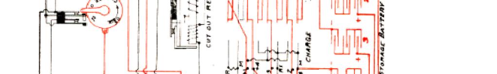
2 This is a description of the 6-24 volt system as applied to the following cars: 1912 Cadillac 1913 Cole Models 4-40, 4-50, Hudson " 37, 54, 1913 Oakland " 42, 6-60, 1913 Oldsmobile " 53, DESCRIPTION - The principal units of the system are: a two-pole motor generator with a single armature winding, which generates at 6 volts and cranks at 24 volts; a storage battery consisting of four groups of three cells each, connected to a controller in such a way as to permit of series or parallel grouping a dual ignition system using current from the generator and also providing for ignition from the dry cells. The system is ungrounded. The lamps used are 6-volt lamps. OPERATION - Figures 1 and 2 cover the typical wiring and circuit diagrams of this system, from which its general characteristics can be obtained. The following cycle of operations is necessary when starting the car with this apparatus. First, the ignition switch button marked "start" is pressed (see Figure 16), which puts the ignition system on the dry cells and gives a vibrating spark. When the starting button is depressed, it closes the circuit around the cut-out relay and through the magnetic latch coil, operating the motor generator as a 6-volt series motor. This causes the armature of the motor generator to revolve at slow speed. The circuits used during the operation of motoring to mesh the gears, are shown in red on the circuit diagram in Fig. 3. With the system in operation as mentioned above, the clutch pedal is pressed down, the gears are meshed and the controller thrown over to the 24-volt side, connecting the series windings of the motor generator directly to the 24-volt battery. As the gears between the motor pinion and the teeth on the flywheel are now meshed, connecting the flywheel directly with the armature of the motor generator, the latter will crank the engine, and at a speed approximately 20 to 30 revolutions per minute. The circuits used during the cranking operation are shown in red in the circuit diagram, Fig. 4. It should be noted particularly that during the cranking operation, the armature of the motor generator is revolving at approximately 20 times engine, speed and therefore is slipping the driving clutch on the front end. Now, when the engine picks up and fires, during the instant that the gears are still in mesh and the engine is running faster than the armature of the motor generator, the starting clutch will be slipping and the driving clutch taking hold. These points should be kept in mind, as they explain the reason for the presence of such clutches in this apparatus, and are necessary to a clear understanding of the operation of the motor generator. When the engine picks up and passes a certain speed, the generator produces a sufficient voltage to close the cut-out relay and then begins to charge the storage battery. The charging circuit is outlined in red in Fig. 5. The lighting and ignition circuits are outlined in red 2
3
4


5
6
7
8 in Fig. 6, so that they may be kept clearly in mind, if it is. Desired to trace out these circuits for testing purposes. MOTOR GENERATORS - The motor generators are of two general designs, both two-pole, the first being a box type machine with two field coils and the second a single coil machine. Figs. 7 and 8 show these machines in section and give a good idea of their general construction. So far as the mechanical construction goes, little need be said, except that all of them have a driving clutch mounted on the front end. CLUTCHES - The driving clutches are keyed to the shaft with a Woodruff key and then pinned in position with a round pin held with a set-screw in the front end of the armature shaft. For starting purposes, a set of sliding gears, in which is incorporated a starting clutch, meshes with the motor pinion and the teeth of the flywheel. Fig. 9 shows, the construction of the clutch. In making adjustments or checking installations, it should be noted that the teeth of the stub gear which mesh with the flywheel teeth should clear the flywheel by approximately 1/8 inch, when the motor pinion has just begun to mesh with the ring gear of the starting clutch. In the case of some of these generators, the starting gears are mounted in the rear housing of the motor generator; in others, they are mounted separately in a special housing bolted to the flywheel housing. MAGNETIC LATCH - On the cars using this system, the little catch operated by the magnetic latch engages with the clutch pedal to operate the controller, which changes over the battery connections to the series connection during the cranking operation. The connections for the magnetic latch are shown in red on the circuit diagram, Fig. 3. The motor is operated as, a series motor on a 6-volt circuit, as mentioned above, with the coil of the magnetic latch in series with the motor. When the clutch pedal is pressed down, it forces the blades of the controller over from the left to the right-hand side, thus connecting the cells of the battery in series. This is done by a link work connecting the handle of the controller to the catch operated by the magnetic latch. 9
9
10
11 CONTROLLER - Fig. 10 shows a front view of the controller and the general arrangement of its blades. Fig. 11 gives a circuit diagram of the controller, including its connections, to the storage battery, ampere hour meter and meter contacts. The meter contacts are connected into the circuit at " C " and " D " (Fig. 11) and are shown in greater detail in Fig. 12. They are designed to either insert resistance in the shunt field of the generator when the battery is charged to a certain extent, thus reducing the charging rate and preventing overcharge of the battery, or to open the field circuit entirely, for a similar purpose. These contacts are operated by the large hand on the ampere hour meter. Their adjustment simply requires that they make good contact and with sufficient pressure between them; in other words, that the contacts be clean and flat and that the blades on which they are mounted shall not have lost their temper. If for any reason they are found in such a condition that their repair does not seem warranted, they should be short circuited by connecting the No. 1 and 2 battery box terminals together permanently with a heavy copper wire. This will cut the meter contacts out of the circuit entirely. At the same time this is done, it will be well to shorten the large meter hand or remove it entirely to prevent a possible ground developing at this point. After cleaning the controller blades, it is necessary to keep them oiled slightly with a light cylinder oil. CUT-OUT RELAY-The adjustment of the cut-out relay has been covered in another article, describing it in detail. This can be had on application. 12
12
13
14
15 AMPERE-HOUR METER - The ampere-hour meter is of the mercury motor type, a section of which is shown in Fig. 13, and is connected into the circuit at the points lettered "A" and "B" in the diagram of the controller shown in Fig. 11, and to the controller itself at No. 3 battery box terminal and at " G, " so that by connecting a heavy copper wire between these points, the meter can be removed for repairs. The little porcelain resistance spool, mounted on its base, is used in connection with the meter contact and has nothing to do whatever with the operation of the meter itself. The meter consists of a disc of copper, floating in a well of mercury and mounted in the magnetic field formed by two or more sets of permanent magnets. The lines of force cut the copper disc at two points. The mercury has about 40 times the resistance of the copper disc, and hence the bulk of current passing through the meter will pass through the disc and approximately in a diametral line. The reaction between the magnetic field, formed by the current passing through the disc in this manner, and the field formed by the permanent magnets, will cause the disc to revolve and at a speed roughly proportional to the current A shunt is placed across the terminals, and by this means it is possible to calibrate the meter. CHARGING SHUNT - The charging rate on these motor generators is adjusted by varying the resistance of the charging shunt Figures. 10 and 14). These shunts come in two sizes, single and double strand. For fast driving the single strand shunt is to be recommended; for slow driving, the double strand. If the shunts burn out, they should not be replaced by copper wire, as the charging rate will then be excessive. The shunt simply divides the charging current with the series field, which is in a reverse direction to the shunt field, and therefore supplies the regulation for this motor generator. If it is shorted out of the circuit entirely, as it will be if a copper charging shunt is placed between the two upper left-hand controller blades, the charging rate will rise to an excessive value, due to the lack of sufficient regulation. If the shunt burns out frequently, or in a very short time, it will tend to indicate that there is a high terminal voltage across the field series, which, in turn, will be caused by poor connections some-where in the generator circuit. When this occurs, therefore, all the terminals in the system, including particularly the battery terminals, the terminals on the motor generator and on the battery box, should be gone over and cleaned and tightened, if found to require this attention. The wires at any junction box should be inspected to make sure 16

16 that the connections have not become loose. The controller blades also should be tested to make sure that they are making good contact. By going over the system in this way, it is possible to eliminate such trouble permanently. OVERHAULING - With regard to overhauling the motor generator, this should be done about once a year, so that the old grease can be cleaned out and replaced by fresh grease, the parts cleaned, the mica on the commutator undercut, if it is high, and the brushes replaced or refitted, if necessary. For details of work on the commutator and brushes, refer to articles on these subjects which can be had on application. GROUNDS - It has been found in a number of cases where grounds have developed in these systems, interfering with the ignition, that they are caused by grounds in the special apparatus which has been added to the system since they were produced, such as extra lights or electric horns of one type or another, and it will be well, where ignition trouble indicates grounds in the system, to disconnect such special apparatus and see if the grounds are not located at this point. CHARGING RATE - When it is desired to test the charging rate of the generator, an ammeter of 30 ampere capacity should be inserted in the line between the generator and the cut-out relay, referring to Fig. 11. This is most easily done by disconnecting the lead going to the outside of the two main terminals of the Cut-Out Relay, lettered No. 1 in the figure, and attaching it to one terminal of the ammeter; then attach the other terminal of the ammeter by a piece of copper wire, to the No. 1 terminal of the cut-out relay. In these systems the charging rate should be approximately 22 amperes as a maximum, although a slight variation either way is permissible to care of the peculiar conditions of driving. 17
17 18
18 IGNITION - The ignition calls far little attention outside of the usual care given such systems. The resistance unit is shown in Fig. 15. The timing is accomplished -by raising the distributor gear and setting it a tooth ahead or a tooth behind. In regard to the exact method of timing, it might be stated that all of the cars using this system are timed so as to permit 1/3 retard and 2/3 advance on the quadrant. In other words, the motor should be timed so that the "mag." contacts are just beginning to break with the engine on No. 1 dead center and the spark lever advanced 1/3 of the way on the quadrant. The ignition switch is shown in Fig. 16, and will be found to give very little trouble indeed. If it is necessary or desirable to test it, a piece of copper wire can be bridged across the terminals used and thus readily show whether or not the contacts specified are giving trouble, due to grit or insufficient pressure between them. If the ignition system is giving trouble of any kind, reference should be made to an article on ignition which covers this subject very completely. Likewise, if it is desired to adjust the ignition relay, reference should be made to a special article in the service Manual on that subject. These articles may be had on application. LUBRICATION - The oiling of the apparatus is a comparatively simple operation. Oil holes are provided for oiling the ball bearings at the front and rear of the motor generator. A grease cup is supplied to lubricate the starting clutch and the shaft on which the starting gears slide and by repacking the driving clutch with grease whenever it becomes dried out, and seeing that the distributor gears are kept properly lubricated and the bottom and top cone ball bearings of the distributor are getting lubricated with a few drops of oil, little trouble should be experienced, due to excessive wear and lack of lubrication. Form 193 Delco M - J. W. P. 19
19
20
INFORMATION. covering use of Ammeter and Voltmeter ON and 1915 Model Six-54 Electrical System
 INFORMATION covering use of Ammeter and Voltmeter ON- 1914 and 1915 Model Six-54 Electrical System Hudson Motor Car Company Detroit, Michigan, IX S. A USE OF AMMETER ON 1914 AND 1915 MODEL SIX-54 With
Battery Operation. Battery Construction. Battery State Of Charge. Battery Load Test. Battery Rating Systems 2/14/12
 Battery Operation Batteries, Charging and Donald Jones Brookhaven College Batteries convert chemical energy into electrical energy During discharge the battery s plate composition is changed During charging
SECTION 9 CRANKING SYSTEM CONTENTS
 SECTION 9 CRANKING SYSTEM CONTENTS 9-1. 9-2. 9-3. 9-4. 9-5. 9-6. 9-7. 9-8. GENERAL DESCRIPTION.,...,..., 9-2 SPECIFICATIONS.......................................... 9-4 LUBRICATION 9-5 REMOVAL AND INSTALLATION...
 1 of 16 1/10/2015 7:25 AM STARTER MOTOR 2009 Hyundai Accent 1.6L Eng GS REQUESTED INFORMATION DISASSEMBLY 1. Disconnect the M-terminal (A) on the magnet switch assembly (B). Fig 1: Identifying M-Terminal
Starting Systems & Traction Motor Systems. ATASA 5 th. ATASA 5 TH Study Guide Chapter 18 Pages Starting & Traction Motor Systems 62 Points
 ATASA 5 TH Study Guide Chapter 18 Pages 537 570 Starting & Traction Motor Systems 62 Points Please Read The Summary 1. Electric are used to start the engine & in hybrids are used to move the vehicle. Motors
STARTER - HITACHI Isuzu Trooper II DESCRIPTION TESTING STARTER PERFORMANCE TESTS Starters HITACHI. Isuzu
 STARTER - HITACHI 1986 Trooper II 1984 Starters HITACHI DESCRIPTION Starter is a conventional 12-volt, 4-pole brush-type motor, with direct or reduction gear drive. The starter-mounted solenoid shifts
2006 MINI Cooper S GENINFO Starting - Overview - MINI
 MINI STARTING SYSTEM * PLEASE READ THIS FIRST * 2002-07 GENINFO Starting - Overview - MINI For information on starter removal and installation, see the following articles. For Cooper, see STARTER WITH
1994 Mazda MX-5 Miata. STARTER - REDUCTION GEAR 1994 ELECTRICAL Mazda Starter - Reduction Gear
 DESCRIPTION STARTER - REDUCTION GEAR 1994 ELECTRICAL Mazda Starter - Reduction Gear The Nippondenso reduction gear starter is a conventional 12-volt, 4-pole, brush-type starter. The integral solenoid is
1997 Mazda MX-5 Miata. STARTER - DIRECT DRIVE 1997 STARTING & CHARGING SYSTEMS Mazda - Starters - Direct Drive
 STARTER - DIRECT DRIVE 1997 STARTING & CHARGING SYSTEMS Mazda - Starters - Direct Drive DESCRIPTION & OPERATION Direct drive starter is a conventional 12-volt, 4-pole, brush-type starter. The integral
1994 Mazda MX-5 Miata. STARTER - DIRECT DRIVE 1994 ELECTRICAL Mazda Starter - Direct Drive
 DESCRIPTION STARTER - DIRECT DRIVE 1994 ELECTRICAL Mazda Starter - Direct Drive Nippondenso direct drive starter is a conventional 12-volt, 4-pole, brush-type starter. The integral solenoid is attached
Starting Systems. State a major safety precaution when removing or working around a starting motor
 Starting Systems State a major safety precaution when removing or working around a starting motor Always unhook the battery ground before attempting to remove the starter motor. Starting Systems Identify
DESCRIPTION & OPERATION
 STARTER - REDUCTION GEAR 1997 STARTING & CHARGING SYSTEMS Mazda - Starters - Reduction Gear DESCRIPTION & OPERATION Reduction gear starter is a conventional 12-volt, 4-pole, brush-type starter. The integral
UNIT 2. INTRODUCTION TO DC GENERATOR (Part 1) OBJECTIVES. General Objective
 OBJECTIVES. General Objective") DC GENERATOR (Part 1) E2063/ Unit 2/ 1 UNIT 2 INTRODUCTION TO DC GENERATOR (Part 1) OBJECTIVES General Objective : To apply the basic principle of DC generator, construction principle and types of DC generator.
DC GENERATOR (Part 1) E2063/ Unit 2/ 1 UNIT 2 INTRODUCTION TO DC GENERATOR (Part 1) OBJECTIVES General Objective : To apply the basic principle of DC generator, construction principle and types of DC generator.
1991 Mazda MX-5 Miata. STARTER - DIRECT DRIVE ELECTRICAL Mazda Starters - Direct Drive ELECTRICAL Mazda Starters - Direct Drive
 DESCRIPTION STARTER - DIRECT DRIVE 1990-92 ELECTRICAL Mazda Starters - Direct Drive Nippondenso direct drive starter is a conventional 12-volt, 4-pole, brush-type starter. The integral solenoid is attached
STARTING SYSTEMS 8B - 1 STARTING SYSTEMS CONTENTS
 TJ STARTING SYSTEMS 8B - 1 STARTING SYSTEMS CONTENTS page DESCRIPTION AND OPERATION STARTER MOTOR... 2 STARTER RELAY... 3 STARTING SYSTEM... 1 DIAGNOSIS AND TESTING STARTER MOTOR... 8 STARTER MOTOR NOISE
Automobile section, showing different parts in detail. and miscellaneous devices.
 SECTION VII Nos. 97 112 Automobile section, showing different parts in detail. and miscellaneous devices. Hydraulic jack MECHANICAL MODELS 43 Section VII 97. Automobile engine starter. This device known
2001 Cougar Workshop Manual
 Page 1 of 7 SECTION 303-06: Starting System 2001 Cougar Workshop Manual DIAGNOSIS AND TESTING Procedure revision date: 09/14/2001 Starting System Refer to Wiring Diagrams Section 303-06 for schematic and
Starting and Charging
 The Starting and Charging System is a critical system in your vehicle. The Starting system provides the ability to crank the engine electrically from the drivers position. The first car with electric starting
Tips & Technology For Bosch business partners
 Tips & Technology For Bosch business partners Current topics for successful workshops No. 05 Trucks Starters and starter systems Part 1 Requirements and functions Internal combustion engines must be cranked
Unit AE01K Knowledge of Locating and Correcting Simple Electrical Faults in the Automotive Workplace
 Assessment Requirements Unit AE01K Knowledge of Locating and Correcting Simple Electrical Faults in the Automotive Workplace Content: Basic electrical principles a. Explain the direction of current flow
THE AUXILIARY EQUIPMENT OF THE CHICAGO, MILWAUKEE AND ST. PAUL LOCOMOTIVES
 952 GENERAL ELECTRIC REVIEW THE AUXILIARY EQUIPMENT OF THE CHICAGO, MILWAUKEE AND ST. PAUL LOCOMOTIVES By L. W. WEBB. RAILWAY EQUIPMENT DEPARTMENT, GENERAL ELECTRIC COMPANY The auxiliary equipment of locomotives
1993 ELECTRICAL Volkswagen Starters - Bosch. Volkswagen; Cabriolet, EuroVan, Golf, GTI, Jetta
 Article Text ARTICLE BEGINNING 1993 ELECTRICAL Volkswagen Starters - Bosch Volkswagen; Cabriolet, EuroVan, Golf, GTI, Jetta DESCRIPTION Starter is a brush type, series-wound electric motor with an overrunning
Automotive Parts. Charging & Starting Systems
 Automotive Parts Charging & Starting Systems Charging Systems Output voltage kept to about 2 volts higher than battery voltage Controlled by varying current into rotor field winding (voltage regulator
./#0#. 1"&." 1994 ELECTRICAL Suzuki of America Corp. - Starters. Swift
 !"" #$%!& '()!)((*(+,*)- 1994 ELECTRICAL Suzuki of America Corp. - Starters Swift Two types of starter motors are used, conventional and reduction gear. Both types of starters consist of yoke assembly,
Electronic Dynamo Regulator INSTRUCTION MANUAL. COPYRIGHT 2014 CLOVER SYSTEMS All Rights Reserved
 DRM TM DRM-HP TM Electronic Dynamo Regulator INSTRUCTION MANUAL COPYRIGHT 2014 CLOVER SYSTEMS All Rights Reserved INTRODUCTION The Clover Systems DRM is a state-of-the art all-electronic voltage and current
ELECTRICAL. Contents - Wiring Diagrams
 Contents - Wiring Diagrams T-Bar (Floating Deck - Hydro)............................................ 8-16 T-Bar (Fixed Deck - Gear)............................................... 8-17 T-Bar (Fixed Deck
ST- 1 STARTING SYSTEM. Page TROUBLESHOOTING... ST-2 STARTER... ST-3 STARTER RELAY... ST- 12 CLUTCH START SWITCH... ST-1 2
 ST- 1 STARTING SYSTEM Page TROUBLESHOOTING... ST-2 STARTER... ST-3 STARTER RELAY... ST- 12 CLUTCH START SWITCH... ST-1 2 ST-2 STARTING SYSTEM - Troubleshooting TROUBLESHOOTING Problem Possible cause Remedy
Electrical Systems. Introduction
 Electrical Systems Figure 1. Major Components of the Car s Electrical System Introduction Electricity is used in nearly all systems of the automobile (Figure 1). It is much easier to understand what electricity
STARTER SYSTEM TESTING 5.6
 STARTER SYSTEM TESTING 5.6 ON-MOTORCYCLE TESTS b088x5x Starter Relay Test NOTE Starter relay test also applies to ignition and key switch relays.. See Figure 5-5. Locate starter relay. The relay is attached
STARTER SYSTEM TESTING 5.6
 STARTER SYSTEM TESTING 5.6 ON-MOTORCYCLE TESTS Starter Relay Test NOTE Starter relay test also applies to ignition and key switch relays.. See Figure 5-5. Locate starter relay. The relay is attached to
1 THE WOLVERTON SYSTEM OF TRAIN LIGHTING.
 1 THE WOLVERTON SYSTEM OF TRAIN LIGHTING. The Wolverton equipment is a single battery system utilising a plain shunt wound dynamo. The dynamo is controlled by an automatic field regulator which senses
Electronic Dynamo Regulator INSTRUCTION MANUAL. COPYRIGHT 2014 CLOVER SYSTEMS All Rights Reserved
 DRM TM DRM-HP TM Electronic Dynamo Regulator INSTRUCTION MANUAL COPYRIGHT 2014 CLOVER SYSTEMS All Rights Reserved INTRODUCTION The Clover Systems DRM is a state-of-the art all-electronic voltage and current
STARTING & CHARGING SYSTEM SECTIONSC CONTENTS IDX
 STARTING & CHARGING SYSTEM SECTIONSC GI MA EM LC EC CONTENTS FE PRECAUTIONS...2 Supplemental Restraint System (SRS) AIR BAG and SEAT BELT PRE-TENSIONER...2 Wiring Diagrams and Trouble Diagnosis...2 BATTERY...3
MAHALAKSHMI ENGINEERING COLLEGE TIRUCHIRAPALLI
 MAHALAKSHMI ENGINEERING COLLEGE TIRUCHIRAPALLI 621213 QUESTION BANK --------------------------------------------------------------------------------------------------------------- Sub. Code : EE2402 Semester
MANUAL TRANSMISSION SERVICE
 MANUAL TRANSMISSION SERVICE Introduction Internal combustion engines develop very little torque or power at low rpm. This is especially obvious when you try to start out in direct drive, 4th gear in a
Moments. It doesn t fall because of the presence of a counter balance weight on the right-hand side. The boom is therefore balanced.
 Moments The crane in the image below looks unstable, as though it should topple over. There appears to be too much of the boom on the left-hand side of the tower. It doesn t fall because of the presence
The Starter motor. Student booklet
 The Starter motor Student booklet The Starter motor - INDEX - 2006-04-07-13:20 The Starter motor The starter motor is an electrical motor and the electric motor is all about magnets and magnetism: A motor
Principles of Electrical Engineering
 D.C GENERATORS Principle of operation of D.C machines, types of D.C Generators, e.m.f equation of D.C Generator, O.C.C of a D.C Shunt Generator, Load characteristics of D.C.Generators GENERATOR PRINCIPLE:
2 Principles of d.c. machines
 2 Principles of d.c. machines D.C. machines are the electro mechanical energy converters which work from a d.c. source and generate mechanical power or convert mechanical power into a d.c. power. These
1950 Pacemaker. Specifications & Adjustments
 Specifications & Adjustments Specifications & Adjustments ENGINE: Valve Arrangement Bore and Stroke Piston Displacement Maximum Torque Horsepower Actual Taxable Compression Ratio: Cast Iron Head (Std.)
Horns, Wiper, and Washer System Operation
 14 Horns, Wiper, and Washer System Operation LEARNING OBJECTIVES Upon completion and review of this chapter, you should be able to: Explain the operation of an automotive horn. Identify the different types
Automotive Electrical Systems
 Automotive Electrical Systems 1 Electrical Circuits Contain 4 main parts 1. Power source battery alternator 2. Load 3. Control 4. Path 2 3 Batteries What is a Battery? An electrochemical device which stores
SURETRAC Construction of SURETRAC Fig. 1
 SURETRAC 1 Construction of SURETRAC SURETRAC is a new type of differential that mainly consists of two shaft hubs, two face cams, 19 cam followers, and a differential case. The shapes of the two face cams
SHORT-STOP. Electronic Motor Brake Type G. Instructions and Setup Manual
 Electronic Motor Brake Type G Instructions and Setup Manual Table of Contents Table of Contents Electronic Motor Brake Type G... 1 1. INTRODUCTION... 2 2. DESCRIPTION AND APPLICATIONS... 2 3. SAFETY NOTES...
Sensors & Controls. Everything you wanted to know about gas engine ignition technology but were too afraid to ask.
 Everything you wanted to know about gas engine ignition technology but were too afraid to ask. Contents 1. Introducing Electronic Ignition 2. Inductive Ignition 3. Capacitor Discharge Ignition 4. CDI vs
Installation Instructions Jeep CJ-7
 Retrofit Steering Column Installation Instructions 1976-86 Jeep CJ-7 For Part # s 1520800010, 152800020, 1520800051 www.ididitinc.com 610 S. Maumee St., Tecumseh, MI 49286 (517) 424-0577 (517) 424-7293
To discover the factors affecting the direction of rotation and speed of three-phase motors.
 EXPERIMENT 12 Direction of Rotation of Three-Phase Motor PURPOSE: To discover the factors affecting the direction of rotation and speed of three-phase motors. BRIEFING: The stators of three-phase motors
Section VI SYSTEM SERVICE BULLETIN REFERENCE NUMBER DATE SUBJECT CHANGES
 Section VI SYSTEM SERVICE BULLETIN REFERENCE NUMBER DATE SUBJECT CHANGES 134 ELECTRICAL SYSTEM CHRYSLER SERVICE MANUAL ELECTRICAL SYSTEM DATA AND SPECIFICATIONS STARTING MOTOR (ALL MODELS) C-67 C-68,C-69
Just what is a starter?
 Just what is a starter? The car starter works by harnessing the power of the automotive battery. The battery supplies electricity to the starter to engage and spin over the engine. Once the ignition key
A/C Generator Systems
 A/C Generator Systems What is the function of the charging system? Provide power for all electrical loads Recharge the starting battery What happens if the charging systems puts out too much power? Voltage
Just what is an alternator?
 Just what is an alternator? An alternator is the device used to produce the electricity the car needs to run and to keep the battery charged. The battery is the heart of your electrical system. But you
DC Series Motors by Thomas E. Kissell Industrial Electronics, Second Edition, Prentice Hall PTR
 Site Help Search NI Developer Zone DC Series Motors by Thomas E. Kissell Industrial Electronics, Second Edition, Prentice Hall PTR Back to Document Table of Contents: Series Motor Diagram Series Motor
Series 1000 and Figure NOTE: The top terminals are showing normally closed at rest and the middle terminals are normally
 38.18.The red wire on the OCR plug carries battery voltage. Behavior: D.C. battery voltage should show-up on a volt meter when the red probe is touched to this terminal and the black probe is grounded,
STARTING SYSTEM STARTING SYSTEM ST 1
 ST1 ST2 Troubleshooting TROUBLESHOOTING Problem Possible cause Remedy Page Engine will not crank Battery charge low Battery cables loose, corroded or worn Clutch start switch faulty (M/T) Neutral start
Induction type Energy meter Construction
 Induction type Energy meter Construction The four main parts of an energy meter are: Driving system Moving system Braking system and Registering system The construction is as shown below: Fig. Construction
BASIC ELECTRICS MECHANICS BASIC LEVEL. An initiative of:
 BASIC ELECTRICS 2 BASIC LEVEL MECHANICS An initiative of: Table of Contents TRANSMISSIONS AND DRIVETRAIN 1. Basic Electrics 1 1.1 Introduction 1 1.2 Charging Circuit 2 1.2.1 The Battery 2 2. Generators
Retro it Steering Column
 Retro it Steering Column INSTALLATION INSTRUCTIONS for 1976-86 CJ5 & CJ7 FOR PART NUMBER S: 1520800010, 1520800020, 1520800051, 1526800010, 1526800020, 1526800051 S I NCE 1986 Instruction # 8000000010
STARTER Mitsubishi Montero DESCRIPTION BENCH TESTING STARTER NO-LOAD TEST ELECTRICAL Mitsubishi Starters. Montero
 STARTER 1993 Mitsubishi Montero 1993 ELECTRICAL Mitsubishi Starters Montero DESCRIPTION The starter is a conventional 12-volt, 4-pole brush-type motor, with gear reduction drive. The starter-mounted solenoid
INTRODUCTION Principle
 DC Generators INTRODUCTION A generator is a machine that converts mechanical energy into electrical energy by using the principle of magnetic induction. Principle Whenever a conductor is moved within a
SECTION 1E ENGINE ELECTRICAL
 SECTION 1E ENGINE ELECTRICAL CAUTION: Disconnect the negative battery cable before removing or installing any electrical unit or when a tool or equipment could easily come in contact with exposed electrical
AC Motors vs DC Motors. DC Motors. DC Motor Classification ... Prof. Dr. M. Zahurul Haq
 AC Motors vs DC Motors DC Motors Prof. Dr. M. Zahurul Haq http://teacher.buet.ac.bd/zahurul/ Department of Mechanical Engineering Bangladesh University of Engineering & Technology ME 6401: Advanced Mechatronics
Engine Electrical System
 Engine Electrical System 3 Foreword This manual has been prepared by experts and specialists of,engineering Department of Saipa Yadak Company to be used as a guide by the repairers of electrical systems.we
Introduction: Electromagnetism:
 This model of both an AC and DC electric motor is easy to assemble and disassemble. The model can also be used to demonstrate both permanent and electromagnetic motors. Everything comes packed in its own
All levers are one of three types, usually called classes. The class of a lever depends on the relative position of the load, effort and fulcrum:
 Página 66 de 232 Mechanisms A mechanism is simply a device which takes an input motion and force, and outputs a different motion and force. The point of a mechanism is to make the job easier to do. The
INSPECTION ST 13 2UZ-FE STARTING STARTER. Terminal 50. Terminal C. Battery. Disconnect Battery. Terminal C. Disconnect. Battery.
 2UZ-FE ARTING ARTER 13 INSPECTION 1. INSPECT ARTER ASSEMBLY NOTICE: These tests must be done within 3 to 5 seconds to avoid burning out the coil. (a) Do pull-in test. (1) Disconnect the field coil lead
CHAPTER THREE DC MOTOR OVERVIEW AND MATHEMATICAL MODEL
 CHAPTER THREE DC MOTOR OVERVIEW AND MATHEMATICAL MODEL 3.1 Introduction Almost every mechanical movement that we see around us is accomplished by an electric motor. Electric machines are a means of converting
DESCRIPTION AND OPERATION > CLUTCH CONTROLS
 Page 1 of 17 2004 Ford Mustang 3.9L Eng Base Service Manual: CLUTCH CONTROLS Print Date: DESCRIPTION AND OPERATION > CLUTCH CONTROLS Fig 1: Identifying Clutch Controls Components Page 2 of 17 The clutch
STARTING SYSTEM (1ZZ FE) (April, 2003)
 (April, 2003)") STARTING & CHARGING STARTING SYSTEM (1ZZ FE) (April, 2003) STARTING SYSTEM (1ZZ FE) (April, 2003) INSPECTION 19 1 190QO 02 1. INSPECT STARTER ASSY NOTICE: These tests must be performed within 3 to 5 seconds
STARTING & CHARGING STARTING SYSTEM (1ZZ FE) (April, 2003) STARTING SYSTEM (1ZZ FE) (April, 2003) INSPECTION 19 1 190QO 02 1. INSPECT STARTER ASSY NOTICE: These tests must be performed within 3 to 5 seconds
ARTICLE BEGINNING DESCRIPTION TROUBLE SHOOTING ON-VEHICLE TESTING REMOVAL & INSTALLATION STARTER DOES NOT CRANK ENGINE
 Article Text ARTICLE BEGINNING 1995-96 STARTING & CHARGING SYSTEMS Volkswagen Starters Cabrio, Golf III, GTI, Jetta III DESCRIPTION Starter is a brush type, series-wound electric motor with an overrunning
Armature Reaction and Saturation Effect
 Exercise 3-1 Armature Reaction and Saturation Effect EXERCISE OBJECTIVE When you have completed this exercise, you will be able to demonstrate some of the effects of armature reaction and saturation in
The Borg Warner Overdrive
 The Borg Warner Overdrive by Tom Endy For the Model A Ford: Over the last 30 years the addition of an overdrive to a Model A Ford drive train has become a popular and practical convenience. The very first
CHAPTER 22 STARTER Models J05C-TD, J08C-TP and TR
 1 INDEX STARTER 22-1 22-114E-03 CHAPTER 22 STARTER TROUBLESHOOTING...22-2 STARTER...22-4 22 22-2 STARTER 1 page 1 TROUBLESHOOTING Symptom Possible cause Remedy Engine does not crank, or cranks slowly Key
Throttle-by-wire. MasterCraft Technical Training Vonore, Tennessee USA. A MasterCraft Technical Services Publication
 Throttle-by-wire MasterCraft Technical Training Vonore, Tennessee USA A MasterCraft Technical Services Publication MasterCraft University 2008-2009 Throttle-by-wire Page 1 Electronic Throttle Control Description
BASIC ELECTRICAL MEASUREMENTS By David Navone
 BASIC ELECTRICAL MEASUREMENTS By David Navone Just about every component designed to operate in an automobile was designed to run on a nominal 12 volts. When this voltage, V, is applied across a resistance,
ITEMS PISTON STOP SECTION 14 TOOLS SPECIAL PART NO PART NO CRANKSHAFTGUIDE D SERIES GOV RNOR ADJUSTING GAUGE C SERIES
 SECTION 14 TOOLS SPECIAL ITEMS PISTON STOP USED ON ALL BOY ENGINES. MODELS OF LAWN- PART NO. 426814 Used to hold flywheel in place while loosening or tightening flywheel nut. Remove spark pug and install
Regulator Model
 Parographs 162-165 Remy Lubricant No. 1960373 and reinstall. Inspect needle bearing (18) in slip ring end frame. This bearing should be renewed if its lubricant supply is exhausted; no attempt to relubricate
DESIGN OF DC MACHINE
 DESIGN OF DC MACHINE 1 OUTPUT EQUATION P a = power developed by armature in kw P = rating of machine in kw E = generated emf, volts; V = terminal voltage, volts p = number of poles; I a = armaure current,
Driver Driven. InputSpeed. Gears
 Gears Gears are toothed wheels designed to transmit rotary motion and power from one part of a mechanism to another. They are fitted to shafts with special devices called keys (or splines) that ensure
MSD 7AL-3, Ignition Control PN 7230
 MSD 7AL-3, Ignition Control PN 7230 Important: Read the instructions before attempting the installation. Parts Included: 1-7AL-3, PN 7230 1 - Parts bag (wires and connectors) 4 - RPM Modules 3000, 7000,
MOTORS. Part 2: The Stepping Motor July 8, 2015 ELEC This lab must be handed in at the end of the lab period
 MOTORS Part 2: The Stepping Motor July 8, 2015 ELEC 3105 This lab must be handed in at the end of the lab period 1.0 Introduction The objective of this lab is to examine the operation of a typical stepping
 ELECTRICAL MEASURING INSTRUMENT CHAPTER 15 ELECTRICAL MEASURING INSTRUMENTS THE MOVING COIL GALVANOMETER The moving coil galvanometer is a basic electrical instrument. It is used for the detection or measurement
Tips & Technology For Bosch business partners
 Tips & Technology For Bosch business partners Current topics for successful workshops No. 05 Trucks Starters and starter systems Part 2 Moderately heavy commercial vehicles with diesel engines having a
IGNITION SYSTEM COMPONENTS AND OPERATION
 69 IGNITION SYSTEM COMPONENTS AND OPERATION Figure 69-1 A point-type distributor from a hot rod being tested on a distributor machine. WARNING: The spark from an ignition coil is strong enough to cause
SECTION 3.00 WARNING WARNING ENGINE STARTUP AND SHUTDOWN PRESTART INSPECTION
 SECTION 3.00 ENGINE STARTUP AND SHUTDOWN PRESTART INSPECTION Be sure that the clutch, circuit breaker, or other main power transmission device is disconnected. Generators develop voltage as soon as the
Electricity. Chapter 20
 Electricity Chapter 20 Types of electric charge Protons + charge Electrons - charge SI unit of electric charge is the coulomb (C) Interactions between charges Like charges repel Opposite charges attract
Institute of Technology, Nirma University B. Tech. Sem. V: Electrical Engineering 2EE305: ELECTRICAL MACHINES II. Handout: AC Commutator Motors
 Institute of Technology, Nirma University B. Tech. Sem. V: Electrical Engineering 2EE305: ELECTRICAL MACHINES II Handout: AC Commutator Motors Prepared by: Prof. T. H. Panchal Learning Objective: Introduction
CHAPTER 10 ELECTRIC SYSTEM
 CHAPTER 10 ELECTRIC SYSTEM 1. ELECTRIC SYSTEM ELECTRIC SYSTEM 1.1 WIRING DIAGRAM CK20-USA 196WA00A S196-WOO Jul. 2003 10-3 CK20(M) CHAPTER 10 CK20-EU 196WA51A 10-4 S196-WOO Jul. 2003 ELECTRIC SYSTEM 1.2
B, are made of %-in. strap iron. Armature
 # 6-32 HACK SCREWS operating on low-voltage a.c. from a bell transformer is shown in Figs. 1 and 3. The field coils A and B are two magnets from a buzzer or doorbell placed so that the windings run in
Reed Technology. standexmeder.com
 Reed Technology standexmeder.com How Reed Switches are used with a Permanent Magnet Using Reed Switches in a sensing environment, one generally uses a magnet for actuation. It is important to understand
DIVISION 7 GENERATORS AND MOTORS
 DIVISION 7 GENERATORS AND MOTORS Principles, Characteristics, and Management of DC Generators (Dynamos).................................... 7.1 Principles, Characteristics, and Management of AC Generators
FRICTION DEVICES: DYNAMOMETER. Presented by: RONAK D. SONI Assistant Professor Parul Institute of Technology, Parul University
 FRICTION DEVICES: DYNAMOMETER Presented by: RONAK D. SONI Assistant Professor Parul Institute of Technology, Parul University DYNAMOMETER A dynamometer is a brake but in addition it has a device to measure
Electronic Dynamo Regulator INSTRUCTION MANUAL. COPYRIGHT 2015 CLOVER SYSTEMS All Rights Reserved
 DR310 TM Electronic Dynamo Regulator INSTRUCTION MANUAL COPYRIGHT 2015 CLOVER SYSTEMS All Rights Reserved INTRODUCTION The Clover Systems DR310 is an allelectronic voltage and current regulator for dynamos
The Knowledge Bank at The Ohio State University. Ohio State Engineer. Electrolysis in Underground Structures
 The Knowledge Bank at The Ohio State University Ohio State Engineer Title: Creators: Issue Date: Publisher: Electrolysis in Underground Structures Rei, P. F. Pepper, H. C. Hoover, C. H. Frankenberg, R.
To Install the Jolley magnetic electronic ignition system and new matched coil and resistor in Daimler Ferret.
 To Install the Jolley magnetic electronic ignition system and new matched coil and resistor in Daimler Ferret. Ignition system parts purchased from Frank Jolley www.classicheads.com First problem is to
ELECTRICAL MAINTENANCE
 ELECTRICAL MAINTENANCE II PRACTICAL JOURNAL DATA 1 EXPERIMENT NO. 1 AIM: TO FIND VOLTAGE RATIO OF A GIVEN TRANSFORMER. CIRCUIT DIAGRAM: OBSERVATION TABLE: Sr.No. 1 2 3 4 Primary Voltage (V 1 ) Secondary
7.9.8 Elctromagnetism
 7.9.8 Elctromagnetism 71 minutes 86 marks Page 1 of 25 Q1. The diagram shows an electromagnet used in a door lock. (a) The push switch is closed and the door unlocks. Explain in detail how this happens.
Unit V HYDROSTATIC DRIVE AND ELECTRIC DRIVE
 Unit V HYDROSTATIC DRIVE AND ELECTRIC DRIVE HYDROSTATIC DRIVE In this type of drives a hydrostatic pump and a motor is used. The engine drives the pump and it generates hydrostatic pressure on the fluid.
ECSE-2100 Fields and Waves I Spring Project 1 Beakman s Motor
 Names _ and _ Project 1 Beakman s Motor For this project, students should work in groups of two. It is permitted for groups to collaborate, but each group of two must submit a report and build the motor
Abbeon Cal, Inc. Model BD-50E HIGH FREQUENCY GENERATOR OPERATING MANUAL
 Abbeon Cal, Inc. Model BD-50E HIGH FREQUENCY GENERATOR OPERATING MANUAL DESCRIPTION. The Model BD-50E is a rugged tester designed for testing tank lining and other applications where extended use is necessary.
The Physics of the Automotive Ignition System
 I. Introduction This laboratory exercise explores the physics of automotive ignition systems used on vehicles for about half a century until the 1980 s, and introduces more modern transistorized systems.