Nanomotion Technical Design Guide
|
|
|
- Jack O’Neal’
- 5 years ago
- Views:
Transcription

1 Nanomotion Technical Design Guide 1
2 Table of Contents Quick Reference Guide 3 Introduction 4 Core Mechanical Design: Managing Normal Force 4 Linear & Rotary Designs 4-10 Mounting Tolerances 11 Motor Sizing Mechanical Assembly Procedures and Safeguards 15 Electrical Interface 16 Servo Tuning 17 General Operation & Safe Guards 18 2
3 Quick Reference Getting Started o Verify proper stage mechanics with preloaded bearings and appropriate stiffness. o Follow Nanomotion s motor mounting guidelines for preloading and motor orientation with respect to travel & verify that ceramic strip has two drops of epoxy o Connect the ground wire from the motor to the amplifier. o Verify the connection (jumper) between power supply return and the controller s analog ground. o Condition the motor before tuning, per Motor Installation Manual (Always recondition the motor each time it is disengaged from the ceramic strip). o After conditioning, wipe the ceramic with a clean cloth and IP alcohol without disengaging the motor o Use Abort on Position Error (or other safety mechanism) and appropriate torque limit during initial integration and conditioning. Do not exceed 5v and 50% duty cycle. o Avoid prolonged operation in an unstable condition (excessive vibration) during tuning process. o Consult with Nanomotion with any questions during the set up process. o Do not operate the motor in an un-loaded (un-mounted) condition. o Do not exceed the duty cycle limits when operating the motor (see Motor Installation Manual). o Do not allow the motor tips to leave contact with the ceramic strip during operation. (Use mechanical hard stops) o Do not remove the cover of the motor (High Voltage Inside). o Do not immerse the motor in any liquids. 3
4 Technical Guidelines for Using Nanomotion Motors Introduction Nanomotion motors provide direct drive performance for linear or rotary motion. Motion is transmitted through the contact of a ceramic finger pushing on a ceramic strip. The friction pair is specifically selected to yield optimum performace with minimal wear, currently achieving 40,000 hours of operation and working in environments up to Class 10 clean rooms. To yield the maximum performance benefits of Nanomotion s ceramic servo motors, it is important to understand the operating characteristics of the piezo ceramic elements and the impact that it has on the mechanical structure. As a direct drive, the Nanomotion motor is sized by the basic principles of F=MA (plus the resistance of the bearing structure & the force of gravity if on an incline or vertical). While this is a basic sizing method, one must recognize that the normal force of Nanomotion s motor directly affects the starting force based on the coefficient friction of the bearing. Additionally, bearing stiffness may be impacted by the motor preload if the bearing preload is not sufficient. Good design practice requires that a proper bearing configuration and bearing preload be established for use with Nanomotion motors. Core Mechanical Design: Managing Normal Force Nanomotion motors apply a normal force, into the bearing structure that is five times greater than the driving force. Simply, an HR1, which provides 1 lb. thrust, will create 5 lbs force into the bearing structure, perpendicular to motion. In addition to the normal force, there is the potential for higher acceleration forces that are placed in the same direction, impacting the bearing. Acceleration forces can easily be 2 to 3 times greater than the normal force. So, an HR1 motor, which provides 1 lb driving thrust has 5 lbs normal force and potentially 15 lbs acceleration force. The forces applied by Nanomotion s motor require that the bearing structure (linear or rotary) have sufficient stiffness (and preload) to support the motor force. Insufficient stiffness could result in vibration transmitted to the mechanical structure, audible noise, excessive wear, and motor burning. Linear Bearing To best manage the normal and acceleration forces of the Nanomotion motor, it is appropriate to have a linear bearing stiffness of 50N/µm. This is easily achievable with conventional bearings that are readily available on the market. From a linear bearing perspective we will consider crossed roller bearings and linear recirculating guides. But, it is perfectly appropriate to consider air bearings and other mechanical bearings that provide the appropriate stiffness. 4
5 The most common linear bearings used in precision motion are crossed rollers and linear recirculating guides. While ball bushings and air bearings are acceptable technologies, they are in the minority for precision motion. For purposes of this document we will define several types of non-recirculating and recirculating linear bearings. For the scope of this document, we will expect that motor mounting on a nonreciruclating bearing has the motor mounted along with the stationary base and the slide plate moves on its own. (The motor is not moving with the slide plate.) Non Recirculating Linear Bearings There are 3 typical configurations of non-recirculating linear bearings shown in Figure 1 Figure 1 Crossed Rollers (left) Steel V-way with ball (center) Needle Roller (Right) Within the scope of these bearings, needle rollers represent the highest stiffness, but crossed roller bearings are the most common. Crossed roller bearing sets or slides typically have a mechanical preload that allows the user to establish a preload or use factory defaults (removing all play in the bearing) and exercise the siffness of the bearing. Crossed rollers are very stiff, typically measuring ~45N/µm, per roller (based on a 6mm diameter), with half the rollers carrying the load. This is perfectly sufficient for Nanomotion motors, however the bearing preload must be independent of the motor preload, meaning do not use the motor itself to create the preload on the bearing. Non-recirulating bearings have a slide plate that moves and a roller strip that moves half the distance of the slide plate. In these instances, it is most appropriate to have the motor mounted on the centerline of the bearing structure, both vertically and horizontally. Figure 2 Vertically, it is most desirable to be in the plane of the bearing, near where the indicator is shown on figure 2. 5
6 Horizontally, it is important be as close to center linearly. The primary objective is to have the motor mounted on the center of the length of the slide. Shown in Figure 3. Figure 3 Off center mounting will contribute to Yaw error and potentially contribute to roller migration. Mounting on center assures that the motor force will not disturbe the bearing. Mount on Center Even with a center mounting, with ultra precision motion systems, the yaw error should be calculated and factored in, as it will impact positioning accuracy. Recirculating Linear Bearings Linear recirculating bearings represent much greater variability, as there are may types of recirculating guides and preload levels. This results in different bearing stiffnesses in different load directions. The initial destinction that is made relates to the contact pattern of a recirculating guide. The primary distinction is a two point or four point contact pattern, with the four point contact referred to as a Gothic Arc. The basic difference between 2 point contact and 4 point contact is that 2 point contact touches the ball on the rolling axis, where 4 point contact has 4 points touching on non rolling axes and induces much more friction into the system. Recirculating Bearing Contact Patterns While 2 point contact (on left) touches on its rolling diameter, it limits the amount of load capacity/stiffness in directions other than pure dyamic load, but maintains lower rolling friction. The 4 point configuration (on right) offers much more loading in moment load capacity, but in turn, has much higher static friction, resulting in more break away force required from the motor. 6
7 In addition to the bearing configuration, the bearing preload is very important as it relates to stiffenss. Recirculating Linear Guides (with balls or rollers) Each recirculating puck can travel up and down the length of a given rail. It is important that each individual puck has a preload. The preload is created by sizing the ball bearings to be larger that the clearance allows, ultimately establishing compression on the balls. As typical configurations use either 2 pucks with a single rail or two parallel rails, with 4 pucks, having a preload on the bearings is essential. Recirculating bearings are typically used for longer travel applications, greater that 150mm, and thus are configured where the motor travels with the slide, always maintaining central contact on the bearing. Attention must also be paid to the recirculating bearing style, as some bearings are better suited to downward loads, while others are suited to equal loads in all directions. Bearings that are suited to downward loads have minimal side load capacity. This coupled with a light preload could result in low stiffness, mechanical noise and potential wear. For reference: THK SSR 15 series is designed primarly for downward load, with some capacity in side direction and poor capacity in the upward direction. THK SHS 15 series is designed for equal loading in all directions Bearing Type Preload Stiffness SSR15 C1 20N/µm SSR15 C0 70N/µm RSR9K C1 20N/µm RSR9Z C1 10N/µm Please note that while these numbers may not appear in the published catalogs, they are suppled by the engineering staff of the linear guide manufacturers. 7
8 Rotary Bearings Rotary applications with Nanomotion motors are quite common as the direct drive motor can eliminate worm gears, belts and other rotary transmissions. In rotary applications there is design flexibility to apply the motor axially, driving on the flat surface of a disk, or radially, driving on the circumference of a ring. Typical Axial Mounting Typical Radial Mounting As with linear bearings, the bearing stiffness is critical to the performance of the Nanomotion motor. Moreover, a single motor applied axially will induce a moment load on the bearing whereas a single motor applied radially will induce a side load on the bearing structure. In many rotary applications it is appropriate to consider the use of two smaller motors, mounted 180º apart to maintain a balanced load on the bearing. Mounting two motors that are not 180º apart, with a slightly different angle, can also help to maintain a preload on the bearing and have a positive impact. In evaluating rotary bearings, there are 3 common types that are utilized in rotary stages: Rotary crossed roller Angular contact Deep groove radial While the same stiffness criteria apply to rotary applications, 50N/µm, each bearing offers different operating characteristics. 8
9 Rotary crossed roller A crossed roller bearing consists of a series of rollers with alternating axes, applied between circular machined V ways. This bearing style is very low profile and provides very high stiffness. However, as the roller bearings are not tapered, larger diameter rollers have much higher friction coefficients, based on the contact pattern. The crossed roller bearing will offer the lowest profile and the ability to work with a single bearing. The bearing can provide sufficient stiffness in a single row, and be utilized in an axial or radial manner. Angular contact Angular contact bearings come in a variety of configurations. There are angles that are designed to provide higher axial load with good radial stiffness and there are contact angles that provide higher radial stiffness with good axial support. Typically the contact angles can range from 14º to 40º, so it is very important to understand the design of the specific bearing. The primary advantage of angular contact bearings is that the contact angle is a two point contact that can support higher preloads, without increasing friction. Theses bearings can provide both precision and load carrying levels in an effective package. Angular contacts are typically provided in matchground sets. These sets are provided for a variety of mounting configurations (front-to-front, backto-back), each yielding different stiffness levels in different directions. Caution must be used in setting up these bearings to avoid mis-applying. If the bearing is reversed from the intended mounting, the load capacity and stiffness will be greatly reduced. DB and DF will provide the axial capacity of one bearing with high radial stiffness. DT will provide double the axial stiffness when applied in the correct orientation, and no stiffness in the reverse direction. 9
10 Deep groove radial Deep groove bearings are acceptable, so long as the stiffness level meets the criteria for use with Nanomotion motors. These bearings utilize ball bearings captured inside a deep groove. They provide low friction and need to be applied in pairs and preloaded. While designed optimally for radial loads, this bearing configuration will be physically the largest, to provide optimum stiffness. Based on the contact angle and the rolling axis, it is most appropriate to use this bearing design when operating radially. Use of this bearing for axial motor mounting will require a large bearing size and is best when multiple motors are spaced around the disk for uniform loading. 10
11 Mechanical Mounting Tolerance The Nanomotion motor is constructed with a spring behind each motor element. This spring is designed to provide a preload (normal force) as well as allow for mounting inaccuracies. The spring can compensate for out of parallel conditions up to 50µm (.002 ). All of the bearing types discussed provide linear accuracies well within these tolerances, but the machined mounting surfaces will contribute to linear accuracy. It should, however, be achievable to control linear straightness to 50µm in a precision motion system. For systems that require ultrahigh resolution (below 100nm) and smooth constant velocity, it is important to maintain tighter tolerances on the straightness of motion, to optimize the servo performance. Motor Sizing Each HR series motor element provides 4.4N (1 lbs) of dynamic stall force. The static holding per element is 75% of the dynamic stall force, so an HR1 motor providing 4.4N of dynamic stall force, provides 3.5N of static holding. Based on using low friction bearings (<.007 Cof), a direct drive motor is sized by using F=MA. In addition to the mass, it is necessary to factor in the starting frictional force based on the coefficient of friction and any inclination of the axis. While it is certainly possible to move large masses with small motors, acceleration and move profile become limited. Using a motor horizontally the following sizing formulas should be evaluated: In sizing a permanent magnet brushless dc motor, acceleration of a load is the primary factor of consideration as the motor will require the most amount of current during this time. The acceleration force requirement is directly related to the motor's peak force capability and current limitations. In sizing a Nanomotion motor, the primary factor is where will the work be done, in terms of speed and force. Identifying the force required at the maximum velocity will ultimately determine which motor(s) can support the application. As ceramic servo motors do not pull peak current during acceleration like a dc motor, it is based on the required speed and force to point to achieve the profile. Below are basic equations (in word format) to understand the sizing process. 11
12 In the equation F = MA Peak Force = Total Mass * Rate of Acceleration The moving mass, however must include all the associated load, such as: Customer weight Slide weight Bearing drag & Cof Cable drag Known Information from a Customer Customer weight to move Move distance (for typical move & total travel) Time to make move (which we break down into accel time, run time, decel time) Cof of bearing structure Thrust force if any (mounting orientation) The Motion Analysis consists of the following: Max Speed = Distance Traveled (mm/sec) Run Time + (Accel Time/2 + Decel Time/2) Max Accel (Decel) = Max Speed (mm/sec^2) Accel (Decel) Time Distance Traveled = Max Speed * Accel (Decel) Time During Accel (Decel) 2 (mm) Distance Traveled = Max Speed * Run Time During Con Velocity (mm) Move Time = Accel Time + Run Time + Decel Time (Sec) Cycle Time = Move Time + Dwell Time (Sec) Duty Cycle = Move Time * 100 (%) Cycle Time 12
13 The Force Analysis Consists of the Following: Acceleration (Decel) Force = Moving Weight * Max Acceleration (Decel) (m/sec 2 ) (N) REVIEW NANOMOTION SIZING TOOL Sizing Example: Requirements: Total moving mass (moving part of stage plus payload), M = 1Kg Travel, X = 0.01 m (horizontal orientation) Total move time, T = 0.1 sec (not including settling time) Motion profile: trapezoidal, accelerate for 1/3 of the total time, move at constant velocity for 1/3 of the total time, decelerate for 1/3 of the total time Calculate: Acceleration / deceleration, A = 4.5 * X / T^2 = 1 * 0.01 / 0.1^2 = 4.5 m/sec^2 Maximum velocity, V = 1.5 * X / T = 1.5 * 0.01 / 0.1 = 0.15 m/sec Acceleration force, Fa = M * A = 1 * 4.5 = 4.5 N Add additional forces (bearing friction, load force, gravity/inclination, etc.) to obtain total force Ft. Let s neglect in this example. Plot the point {Ft,V} on the Force/Velocity curves. See figure below. Select the motor whose curve is above the {Ft,V} point. In this case it would be an HR4. Force [N] Force vs Velocity, HR Series Velocity [m/sec] Force/Velocity Nodal Point Linear (HR1) Linear (HR2) Linear (HR8) Linear (HR4) 13
14 Settling Time The achievable settling time is mainly dictated by the damping of the motor and the natural frequency of the system. A typical number of three cycles is required for the motor damping to damp the system vibration along the motion axis, so the settling time will be roughly according to the following formula: T s = 3/Fr Where Fr is the natural frequency of the system, and is calculated according to the following formula: Fr = 1 2π K m Where: K - stiffness of the motor in Newton/meter m - mass of the moving part in Kg If the desired natural frequency is higher than the one calculated for a given configuration, adding another motor in parallel or in tandem will increase the system s natural frequency due to the increased stiffness. The combined stiffness of several motors is the algebraic sum of the stiffness of the individual motors. One should recalculate the natural frequency using the combined stiffness of the motors. It is worthwhile to note that the effective motor stiffness increases under close loop operation. Driving vertically with a motor that actuates based on friction requires specific consideration to the static load, separate from the dynamic force. As a rule of thumb, each 4.4N element can drive 120 grams vertically. Beyond this a counter balance should be considered. This can be in the form of a spring, a continuous force gas spring, or opposing weight. 14
15 Mechanical Assembly Procedures and Safeguards WARNING: NEVER OPERATE THE MOTOR UN-LOADED, WITHOUT PRELOAD AGAINST A NANOMOTION DRIVE STRIP. Proper mounting procedures are described in each motor manual, with preload being set by a shim (provided with ST, HR1 & HR2 motors), or a cam (internal to the HR4 & HR8 motors). The motor should be mounted perpendicular to travel, with the arrows on the motor label indicating the direction of travel. In applications utilizing the HR4 & HR8 motors, it is important to avoid compressing the motor against the ceramic strip, prior to engaging the cams. This additional force will result in a higher that expected preload. If there is a concern about controlling the force during mounting it is acceptable to use a shim, when the fingertips are in a retracted position, up to 15µm thickness. This will assure that the motor elements are not over compressed against the drive strip. Always make sure the mechanical travel does not permit the motor fingers to become disengaged from the ceramic drive strip. The fingertips should remain in a compressed state at all times. Most Nanomotion provided drive strips have a 3M acrylic tape bonded to them. Nanomotion can provide the specification on the tape for those customers who require it. When applying the ceramic with the tape, make sure there are no air bubbles and the ceramic strip is applied to a clean surface. After adhering the drive strip, secure it with two drops of epoxy, per the instructions in the manual, to prevent any motion in sheer. 15
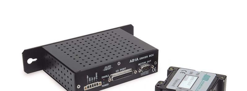
16 Electrical Interface Nanomotion s motors run at resonant frequency and are sensitive to the capacitance of the electrical circuit. Changing cable lengths will affect the total capacitance. There are guidelines provided in Nanomotion s catalog and manuals as to the acceptable cable lengths. In addition to the cable length from the motor to the amplifier, caution should be used if third party cable is used. Nanomotion provides motors with specific low capacitance cable at: Standard motors: 64pF/foot Vacuum motors: 13pF/foot If the capacitance of the electrical circuit is too high, the full performance of the motor will not be realized. Nanomotion can provide guidelines for testing capacitance. Motor Connection o Connect a ground wire from the motor to the amplifier chassis screw. o Connect the amplifier s analog ground to the controller s analog ground (even when using differential command). o Tie un-used +Vin or Vin amplifier inputs to amplifier s analog ground. o For AB1A, AB2 and AB4: need the controller to generate an active low enable signal (ACTIVE = short to ground.) AB5 supports both active high and active low. Conditioning (burn-in) o Must condition motor before tuning and any time after a motor has been removed and re-mounted o Limit command to 5V and use Abort on Position Error at the controller to protect the motor during initial integration and conditioning. o Conditioning cycle: 4 hours minimum at 50 mm/sec, 50% duty cycle max, running end-to-end in an open loop condition. The CCS drive strip should condition for ~18 to 20 hours o Condition at ambient never in vacuum o At the end, wipe the ceramic with isopropyl alcohol without retracting the fingers 16
17 Tuning Nanomotion offers a variety of amplifiers that provide a wide range of performance benefits. From a tuning perspective, there are 2 main differences between the amplifiers that should be understood: 1. The AB5 amplifier, which linearizes the voltage to velocity profile and can work with any servo controller. 2. The AB1A, AB2, and AB4 which has a dead-band and should use a simple firmware algorithm to facilitate good performance The Voltage to Velocity profile is represented in a simple graph as shown. When using the AB1A, AB2, or AB4 the following controllers have Nanomotion approved firmware algorithms: Velocity Profile with AB5 ACS Tech80 Acroloop (Parker Compumotor) Delta Tau Galil MEI National Instruments Nyquist ~ ±1 volt deadband Typical Profile with AB1A, AB2, AB4 Voltage The use of the deadband algorithm requires that command threshold be established, which is the point when motion starts. This point can typically range between.8 and 1.5 volts. Depending on the specific drive, motor and mechanical structure, the deadband can be slightly higher or lower. Once the deadband value is identified, establish the command setting at 60% to 70% of this number. So if the deadband measured ±1 volt, establish.6 to.7 volts as the deadband. This number may not necessarily be the same in both directions. The AB5 amplifier utilizes typical tuning values, similar to that of a brushless dc motor. There is no need for any special algorithm and tuning can start with Kp (leaving Ki & Kd at zero). Kp will provide stiffness of the system, Kd will provide damping and Ki will support the ability to achieve final positioning. Once the tuning parameters have yielded the desired performance vary each parameter by +/- 20% and re-confirm performance. This will ensure that the parameters are robust and capable of supporting any small changes in the mechanical structure. 17
18 Operation o o o Do not exceed the Envelop of Performance (published in motor manuals and catalogs) when running motor. If there are questions regarding the specific curve the system is operating on, it is prudent to limit the voltage to 5V from the controller or reduce the duty cycle to 50% until it is determined what is required for the application. For operation in vacuum, a limit of 30% duty cycle is prudent. When using the AB5 amplifier, it is recommended to disable the amplifier after reaching the desired position. This will reduce the operating temperature and increase the life of the system. For all vacuum and UHV motors it is particularly important to utilize this feature. General Safety Precautions o Do not remove the cover of the motor. High voltage inside! o Do not immerse the motor in any solvent or cleaning agent. o Use only a dry, clean, lint free cloth to wipe the motor. 18
Precision Motion Control
 Precision Motion Control A Johnson Electric Company Based on the principles of ultrasonic standing waves in piezoelectricity, Nanomotion introduces its most advanced series of electronic motors, operating
TRANSLATION (OR LINEAR)
") 5) Load Bearing Mechanisms Load bearing mechanisms are the structural backbone of any linear / rotary motion system, and are a critical consideration. This section will introduce most of the more common
5) Load Bearing Mechanisms Load bearing mechanisms are the structural backbone of any linear / rotary motion system, and are a critical consideration. This section will introduce most of the more common
Features of the LM Guide
 Features of the Functions Required for Linear Guide Surface Large permissible load Highly rigid in all directions High positioning repeatability Running accuracy can be obtained easily High accuracy can
Features of the LM Guide
 Features of the Functions Required for Linear Guide Surface Large permissible load Highly rigid in all directions High positioning repeatability Running accuracy can be obtained easily High accuracy can
Ultra Series: Crossed Roller Ultra Precision Stages
 Ultra Series: Crossed Roller Ultra Precision Stages Bayside Motion Group, has developed Ultra Positioning Stages for applications requiring the ultimate in accuracy. Available with a linear motor, ball
Motor Technologies Motor Sizing 101
 Motor Technologies Motor Sizing 101 TN-2003 REV 161221 PURPOSE This technical note addresses basic motor sizing with simple calculations that can be done to generally size any motor application. It will
User Manual. HR Motors. Document No. HR Rev D 11/2018
 User Manual HR Motors Document No. HR00458000-00 Rev D 11/2018 Nanomotion Ltd. POB 623, Yokneam 20692, Israel Tel: 972-73-2498000 Fax: 972-73-2498099 Web Site: www.nanomotion.com E-mail: nano@nanomotion.com
T-MAX SERIES Direct Drive Rotary Servo
 T-MAX SERIES Direct Drive Rotary Servo T-MAX SERIES Direct Drive Rotary Servo Low Profile Direct-drive Rotary Stage Smooth Brushless Servo-drive Positioning Motion Integrated High Resolution Rotary Encoder
Extruded Positioning Stage
 Extruded Positioning Stage Single-axis stage Turnkey operation Modular aluminum construction with integral brushless linear motor, linear encoder, limit switches, cable carrier, linear bearings and bellows
Screw Driven automation tables
 automation tables Precise multi-axis positioning systems play an integral part in today s semiconductor, computer peripheral, solar power, flat panel, life sciences, lab automation, biomedical and electronics
Lecture 19. Magnetic Bearings
 Lecture 19 Magnetic Bearings 19-1 Magnetic Bearings It was first proven mathematically in the late 1800s by Earnshaw that using only a magnet to try and support an object represented an unstable equilibrium;
Replace your belt, ball screw or rack and pinion mechanism with a simple and economical linear servo motor actuator
 LINEAR SERVO ECONO-SLIDE Ultimate Solution for High Throughput Precision Positioning Replace your belt, ball screw or rack and pinion mechanism with a simple and economical linear servo motor actuator
Linear Drive with Ball Screw Drive Series OSP-E..SB
 Linear Drive with Ball Screw Drive Series OSP-E..SB Contents Description Data Sheet No. Page Overview 1.30.001E 47-50 Technical Data 1.30.002E-1 to 5 51-55 Dimensions 1.30.002E-6, -7 56-57 Order instructions
Motor Type Selection. maxon s EC 4-pole brushless motors
 Motor Type Selection Parameters that define a motor type are the mechanical output power, the shaft bearing system, the commutation system used, and the possible combinations with gearheads and sensors.
Application Information
 Moog Components Group manufactures a comprehensive line of brush-type and brushless motors, as well as brushless controllers. The purpose of this document is to provide a guide for the selection and application
SOME FACTORS THAT INFLUENCE THE PERFORMANCE OF
 SOME FACTORS THAT INFLUENCE THE PERFORMANCE OF Authored By: Robert Pulford Jr. and Engineering Team Members Haydon Kerk Motion Solutions There are various parameters to consider when selecting a Rotary
QuickStick Repeatability Analysis
 QuickStick Repeatability Analysis Purpose This application note presents the variables that can affect the repeatability of positioning using a QuickStick system. Introduction Repeatability and accuracy
LEAD SCREWS 101 A BASIC GUIDE TO IMPLEMENTING A LEAD SCREW ASSEMBLY FOR ANY DESIGN
 LEAD SCREWS 101 A BASIC GUIDE TO IMPLEMENTING A LEAD SCREW ASSEMBLY FOR ANY DESIGN Released by: Keith Knight Kerk Products Division Haydon Kerk Motion Solutions Lead Screws 101: A Basic Guide to Implementing
Classification and Characteristics of Rolling Bearings
 1. Classification Characteristics of Rolling Beas 1.1 Rolling bea construction Most rolling consist of s with raceway (inner outer ), rolling elements (either balls or rollers) cage. The cage separates
Linear Drive with Toothed Belt Series OSP-E..B. Contents Description Overview Technical Data Dimensions Order Instructions 46
 Linear Drive with Toothed Belt Contents Description Page Overview 35-38 Technical Data 39-43 Dimensions 44-45 Order Instructions 46 35 The System Concept ELECTRIC LINEAR DRIVE FOR POINT-TO-POINT APPLICATIONS
Kaydon white paper The thin section bearing of today
 The thin section bearing of today by Joe Zagar, engineering specialist an SKF Group brand Thin section bearings provide space, save weight The ubiquitous ball bearing was a workhorse of industry throughout
Repeatability. Prototyping. High Precision Lead Screws
 High Repeatability High accuracy Short Lead times Fast Prototyping High Precision Lead Screws Offering smooth, precise, cost effective positioning, lead screws are the ideal solution for your application.
Config file is loaded in controller; parameters are shown in tuning tab of SMAC control center
 Forces using LCC Force and Current limits on LCC The configuration file contains settings that limit the current and determine how the current values are represented. The most important setting (which
Linear Drive with Toothed Belt and Integrated Guide with Recirculating Ball Bearing Guide with Roller Guide Series OSP-E..BHD
 Linear Drive with and Integrated Guide with Recirculating Ball Bearing Guide with Roller Guide Contents Description Page Overview 11-14 Version with Recirculating Ball Bearing Guide Technical Data 15-17
Integrating piezo. components in. system solutions. The number and variety of piezo applications is growing in all industries, such as semicon,
 Integrating piezo components in system solutions The number and variety of piezo applications is growing in all industries, such as semicon, medical, aerospace, consumer and industrial. HEINMADE, based
Cam Motion Case Studies #1 and # 2
 Cam Motion Case Studies #1 and # 2 Problem/Opprtunity: At an operating speed of 150 to 160 rpm, Cam Motion #1 causes the cam follower to leave the cam surface unless excessive air pressure is applied to
Technical Specifications
 Technical Specifications Overview RollerDrive CNC The answer for a CNC rotary axis Pure Motion By Zero-Backlash Technology TM The RollerDrive CNC, a CNC rotary table, is designed to fulfill the demands
RC3 Ultrasonic Motor User Manual
 RC3 Ultrasonic Motor User Manual D/N: RC03458000-00 REV: F August 29, 2012 Nanomotion Ltd. POB 623, Yokneam 20692, Israel Tel: 972-73-2498000 Fax: 972-73-2498099 Web Site: www.nanomotion.com E-mail: nano@nanomotion.com
STICTION/FRICTION IV STICTION/FRICTION TEST 1.1 SCOPE
 Page 1 of 6 STICTION/FRICTION TEST 1.0 STICTION/FRICTION TEST 1.1 SCOPE Static friction (stiction) and dynamic (running) friction between the air bearing surface of sliders in a drive and the corresponding
Mounting Overlap Shield. Face Clamps. Gap. Seat Depth. Lead In Chamfer. Loose Fit.
 Mounting Introduction: Reali-Slim thin section ball bearings have a crosssection thickness that is much thinner than standard bearings of the same diameter, and are therefore more sensitive to shaft and
HARMONIC GEARHEAD. Features & Benefits Specifications... 53
 HARMOIC GEARHEAD exen s revolutionary (HG) is the perfect combination of size and precision. Use the integrated with exen s RPS Pinion (HGP) to create a true backlash-free solution from the motor to the
ALAR Series Direct Drive, Large-Aperture, Rotary Stage
 ALAR Series Direct Drive, Large-Aperture, Rotary Stage 5 different aperture sizes: 100 mm, 150 mm, 200 mm, 250 mm, 325 mm Continuous or limited travel Axial load capacity up to 595 kg Rotary Stages ALAR
Linear Shaft Motors in Parallel Applications
 Linear Shaft Motors in Parallel Applications Nippon Pulse s Linear Shaft Motor (LSM) has been successfully used in parallel motor applications. Parallel applications are ones in which there are two or
Inner block. Grease nipple. Fig.1 Structure of LM Guide Actuator Model KR
 LM Guide ctuator Model LM Guide + all Screw = Integral-structure ctuator Stopper Housing all screw Inner block Grease nipple Outer rail earing (supported side) Housing Stopper Double-row ball circuit earing
stage from resolution accuracies is 400 peak) and the from an to outpu positioning (as shown N] continuous continuous needs
![stage from resolution accuracies is 400 peak) and the from an to outpu positioning (as shown N] continuous continuous needs](/thumbs/80/81553844.jpg "stage from resolution accuracies is 400 peak) and the from an to outpu positioning (as shown N] continuous continuous needs") Earthquake Simulation Using Single or Dual-Axis Linear Motion Stages With the goal of safer buildings and saving lives, scientists and engineers, through the simulation of many recent earthquakes, need
Earthquake Simulation Using Single or Dual-Axis Linear Motion Stages With the goal of safer buildings and saving lives, scientists and engineers, through the simulation of many recent earthquakes, need
Ball Bearing Positioners miniature and standard
 all earing Positioners miniature and standard Parker Daedal precision linear stages provide controlled, precise pointto-point positioning along a linear axis. Stages are comprised of two basic components:
PRECISION BELLOWS COUPLINGS
 PRECISION BELLOWS COUPLINGS Bellows couplings are used where precise rotation, high speeds, and dynamic motion must be transmitted. They exhibit zero backlash and a high level of torsional stiffness, offering
Linear Actuator with Ball Screw Series OSP-E..S. Contents Description Overview Technical Data Dimensions 89
 Linear Actuator with Ball Screw Series OSP-E..S Contents Description Page Overview 79-82 Technical Data 83-88 Dimensions 89 79 The System Concept ELECTRIC LINEAR ACTUATOR FOR HIGH ACCURACY APPLICATIONS
Courtesy of Steven Engineering, Inc - (800) PATENTED
 PATENTED") PRECISION RING DRIVE SYSTEMS Based on Nexen s innovative Roller Pinion technology, Nexen Ring Drive Systems come complete with a precision grade, high capacity bearing and drive mechanism in a rigid housing.
PRECISION RING DRIVE SYSTEMS Based on Nexen s innovative Roller Pinion technology, Nexen Ring Drive Systems come complete with a precision grade, high capacity bearing and drive mechanism in a rigid housing.
Introduction. Kinematics and Dynamics of Machines. Involute profile. 7. Gears
 Introduction The kinematic function of gears is to transfer rotational motion from one shaft to another Kinematics and Dynamics of Machines 7. Gears Since these shafts may be parallel, perpendicular, or
Stopping Accuracy of Brushless
 Stopping Accuracy of Brushless Features of the High Rigidity Type DGII Series Hollow Rotary Actuator The DGII Series hollow rotary actuator was developed for positioning applications such as rotating a
FTP Series HIGH FORCE ELECTRIC PRESS ACTUATOR
 FTP Series HIGH FORCE ELECTRIC PRESS ACTUATOR Ideal hydraulic press replacement Industry-leading power density Rugged and reliable Flexible and precise 952.500.6200 www.exlar.com 75 FTP Series High Force
Theory of Machines. CH-1: Fundamentals and type of Mechanisms
 CH-1: Fundamentals and type of Mechanisms 1. Define kinematic link and kinematic chain. 2. Enlist the types of constrained motion. Draw a label sketch of any one. 3. Define (1) Mechanism (2) Inversion
Miniature Ball Rail Systems
 R310EN 2210 (2004.06) The Drive & Control Company 2 Bosch Rexroth AG Linear Motion and Assembly Technologies Miniature-BRS R310EN 2210 (2004.06) Linear Motion Systems Ball Rail System Standard Ball Rail
SHS. Caged Ball LM Guide Global Standard Size Model SHS. Point of Selection. Point of Design. Options. Model No. Precautions on Use
 Caged Ball LM Guide Global Standard Size Model LM block LM rail Endplate End seal 45 Ball Ball cage Cross section 45 * For the Ball Cage, see. Point of Selection Point of Design Options Model No. Precautions
White Paper. Phone: Fax: Advance Lifts, Inc. All rights reserved.
 White Paper TURNTABLE AppLicATioN GUidE This section covers the full range of turntables manufactured by Advance Lifts. The basic information necessary to select an appropriate turntable for an application
Quantum Series Size 17, 23, 34 and 56 Brushless Servo Motors Frameless and Housed Engineering Guide
 MACCON GmbH Kübachstr.9 D-81543 München Tel +49-89-65122()-21 Fax +49-89-655217 Quantum Series Size 17, 23, 34 and 56 Brushless Servo Motors Frameless and Housed Engineering Guide Selection Guide Quantum
Six keys to achieving better precision in linear motion control applications
 profile Drive & Control Six keys to achieving better precision in linear motion control applications Achieving precise linear motion Consider these factors when specifying linear motion systems: Equipped
Riverhawk Company 215 Clinton Road New Hartford NY (315) Free-Flex Flexural Pivot Engineering Data
 Free-Flex Flexural Pivot Engineering Data") Riverhawk Company 215 Clinton Road New Hartford NY (315)768-4937 Free-Flex Flexural Pivot Engineering Data PREFACE Patented Flexural Pivot A unique bearing concept for applications with limited angular
Riverhawk Company 215 Clinton Road New Hartford NY (315)768-4937 Free-Flex Flexural Pivot Engineering Data PREFACE Patented Flexural Pivot A unique bearing concept for applications with limited angular
Extruded Positioning Stage
 Sold by Servo Systems Co. 53 Green Pond Road, Suite #2 Rockaway, NJ 07866 Toll Free: (800) 922-1103 Phone: (973) 335-1007 Fax: (973) 335-1661 www.servosystems.com Extruded Positioning Stage The Extruded
A superior alternative to hydraulic or pneumatic motion providing 15 times the life of a ball screw. Planetary Roller Screws
 A superior alternative to hydraulic or pneumatic motion providing 15 times the life of a ball screw Planetary Roller Screws Exlar Your Linear Motion Experts Exlar Corporation is committed to providing
Transmission Error in Screw Compressor Rotors
 Purdue University Purdue e-pubs International Compressor Engineering Conference School of Mechanical Engineering 2008 Transmission Error in Screw Compressor Rotors Jack Sauls Trane Follow this and additional
Rodless Pneumatic Cylinders Series OSP-P
 Rodless Pneumatic Cylinders Series OSP-P System Concepts & Components... 2-5 Technical Data... 7-9 Dimensions... 10-15 Active rakes... 16-19 Accessories (Mounts & Supports)... 20-29 Ordering Information...30
Courtesy of CMA/Flodyne/Hydradyne Motion Control Hydraulic Pneumatic Electrical Mechanical (800)
") 01_1 Miniature st Headline_36 Ball Rail pt/14.4 Systems mm second line 2 Linear Motion and Assembly Technologies Miniature Ball Rail Systems Ball Rail Systems Roller Rail Systems Linear Bushings and Shafts
01_1 Miniature st Headline_36 Ball Rail pt/14.4 Systems mm second line 2 Linear Motion and Assembly Technologies Miniature Ball Rail Systems Ball Rail Systems Roller Rail Systems Linear Bushings and Shafts
Driven Damped Harmonic Oscillations
 Driven Damped Harmonic Oscillations Page 1 of 8 EQUIPMENT Driven Damped Harmonic Oscillations 2 Rotary Motion Sensors CI-6538 1 Mechanical Oscillator/Driver ME-8750 1 Chaos Accessory CI-6689A 1 Large Rod
Ball Rail Systems RE / The Drive & Control Company
 Ball Rail Systems RE 82 202/2002-12 The Drive & Control Company Rexroth Linear Motion Technology Ball Rail Systems Roller Rail Systems Standard Ball Rail Systems Super Ball Rail Systems Ball Rail Systems
Linear Actuator with Ball Screw Series OSP-E..S. Contents Description Overview Technical Data Dimensions 79
 Linear Actuator with Ball Screw Series OSP-E..S Contents Description Page Overview 71-74 Technical Data 75-78 Dimensions 79 71 The System Concept ELECTRIC LINEAR ACTUATOR FOR HIGH ACCURACY APPLICATIONS
Ball. Ball cage. Fig.1 Structure of Caged Ball LM Guide Actuator Model SKR
 Caged all LM Guide Actuator Model Inner block all screw shaft Grease nipple Outer rail all cage all Structure and Features Fig.1 Structure of Caged all LM Guide Actuator Model Caged all LM Guide Actuator
Sensor-Bearing Units Steer-By-Wire Modules Mast Height Control units Other sensorized units
 Mechatronics Sensor-Bearing Units... 957 Steer-By-Wire Modules... 967 Mast Height Control units... 969 Other sensorized units... 971 955 Sensor-Bearing Units SKF Sensor-Bearing Units... 958 SKF Explorer
SPMM OUTLINE SPECIFICATION - SP20016 issue 2 WHAT IS THE SPMM 5000?
 SPMM 5000 OUTLINE SPECIFICATION - SP20016 issue 2 WHAT IS THE SPMM 5000? The Suspension Parameter Measuring Machine (SPMM) is designed to measure the quasi-static suspension characteristics that are important
Motor Tuning Instructions
 6/20/12 Motor Tuning Instructions Before you begin tuning: 1. Make sure Pro-Motion is installed. 2. Hook up motor drive, motor, and computer. - Connect motor drive to computer using a USB to Serial Com
Precision Modules PSK
 Precision Modules PSK The Drive & Control Company Rexroth Linear Motion Technology Ball Rail Systems Roller Rail Systems Standard Ball Rail Systems Super Ball Rail Systems Ball Rail Systems with Aluminum
Ball Bearing Positioners miniature and standard
 all earing Positioners miniature and standard Parker Daedal precision linear stages provide controlled, precise pointto-point positioning along a linear axis. Stages are comprised of two basic components:
506E. LM Guide Actuator General Catalog
 LM Guide Actuator General Catalog A LM Guide Actuator General Catalog A Product Descriptions 506E Caged Ball LM Guide Actuator Model SKR.. A2-4 Structure and Features... A2-4 Caged Ball Technology... A2-6
Hydraulic Proportional and Closed Loop System Design
 Hydraulic Proportional and Closed Loop System Design Neal Hanson Product Manager Industrial Valves and Electrohydraulics 1 Electrohydraulics Contents 1. Electrohydraulic Principles 2. Proportional Valve
ISOMOVE. Mechanical actuators ISO 6431
 ISOMOVE Mechanical actuators ISO 6431 ISOMOVE INDEX 2 Introduction 4 Mounting information and advices 6 10 40 14 20 63 25 80 29 33 Overall dimensions INTRODUCTION GENERAL FEATURES The ISOMOVE actuators
Config file is loaded in controller; parameters are shown in tuning tab of SMAC control center
 Measuring Forces Force and Current limits on LCC The configuration file contains settings that limit the current and determine how the current values are represented. The most important setting (which
RE / STAR Tolerance Rings STAR Ball Knobs, Knob and Lever Type Handles
 RE 2 970/.99 STAR Tolerance Rings STAR Ball Knobs, Knob and Lever Type Handles STAR Tolerance Rings Product Overview Tolerance rings are made of hard, embossed spring steel strip and belong to the class
Linear Actuator with Toothed Belt Series OSP-E..B
 Linear Actuator with Toothed Belt Series OSP-E..B Contents Description Data Sheet No. Page Overview 1.20.001E 21-24 Technical Data 1.20.002E-1 to 5 25-29 Dimensions 1.20.002E-6 30 Order Instructions 1.20.002E-7
Crossed Roller Bearing Positioners
 rossed Roller earing Positioners Parker Daedal precision crossed roller stages provide controlled, precise point-to-point positioning along a linear axis. Stages are comprised of two basic components:
Seals Stretch Running Friction Friction Break-Out Friction. Build With The Best!
 squeeze, min. = 0.0035 with adverse tolerance build-up. If the O-ring is made in a compound that will shrink in the fluid, the minimum possible squeeze under adverse conditions then must be at least.076
Studying the Positioning Accuracy
 Ball Screw Studying the Positioning Accuracy Causes of Error in the Positioning Accuracy Point of Selection Studying the Positioning Accuracy The causes of error in the positioning accuracy include the
Advanced-High Force Linear Motors. User s Manual
 Advanced-High Force Linear Motors User s Manual 4000 & 5000 Series Linear Motors UM-101 Revision A California Linear Devices, Inc. 2236 Rutherford Road, Ste. 119 Carlsbad, CA 92008 Ph: 760-603-8026, Toll
Linear Motion Technology Handbook. The Drive & Control Company
 Linear Motion Technology Handbook The Drive & Control Company 1-2 Bosch Rexroth AG Linear Motion Technology Handbook R310EN 2017 (2006.07) Linear Motion and Assembly Technologies www.boschrexroth.com/brl
Overview of Air Bearings and Design Configurations Richard Pultar OPTI521 December 14, 2016
 Overview of Air Bearings and Design Configurations Richard Pultar OPTI521 December 14, 2016 Introduction Air bearings are a type of bearing that use pressurized air to create an air gap between two surfaces.
Features of the Ball Screw
 Features of the Driving Torque One Third of the Sliding Screw With the, balls roll between the screw shaft and the nut to achieve high effi ciency. Its required driving torque is only one third of the
TECHNICAL INFORMATION
 General Nomenclature Spherical Roller Bearings The spherical roller bearing is a combination radial and thrust bearing designed for taking misalignment under load When loads are heavy, alignment of housings
Miniature Positioners linear motor and screw driven stages
 linear motor and screw driven stages Miniaturization of fiber optics, photonics, electronics and biomedical processes has driven the need for smaller and more efficient positioners. Parker offers numerous
Introducing Galil's New H-Bot Firmware
 March-16 Introducing Galil's New H-Bot Firmware There are many applications that require movement in planar space, or movement along two perpendicular axes. This two dimensional system can be fitted with
LANSCE WIRE SCANNING DIAGNOSTICS DEVICE MECHANICAL DESIGN
 LANSCE WIRE SCANNING DIAGNOSTICS DEVICE MECHANICAL DESIGN Sergio Rodriguez Esparza, Los Alamos National Laboratory, Los Alamos, NM USA INTRODUCTION The Los Alamos Neutron Science Center (LANSCE) is one
Rules of Actuator and Guide Alignment in Linear Motion Systems
 Rules of Actuator and Guide Alignment in Linear Motion Systems By Gary Rosengren, Director of Engineering Tolomatic, Inc. About the Author Gary Rosengren is Director of Engineering at Tolomatic and has
LM Guide Actuator KR. For details, visit THK at CATALOG No E. Product information is updated regularly on the THK website.
 LM Guide Actuator KR For details, visit THK at www.thk.com Product information is updated regularly on the THK website. CATALOG No.209-10E Integrated LM Guide and all Screw High-rigidity / High-precision
LEAD SCREW LINEAR ACTUATORS: WHEN TO APPLY EXTERNAL, NON-CAPTIVE AND CAPTIVE STEP MOTOR ACTUATORS
 LEAD SCREW LINEAR ACTUATORS: WHEN TO APPLY EXTERNAL, NON-CAPTIVE AND CAPTIVE STEP MOTOR ACTUATORS Authored By: Frank Morton and Engineering Team Members Haydon Kerk Motion Solutions A common way to generate
Compact Modules. with ball screw drive and toothed belt drive R310EN 2602 ( ) The Drive & Control Company
 The Drive & Control Company") with ball screw drive and toothed belt drive R310EN 2602 (2007.02) The Drive & Control Company Bosch Rexroth AG Linear Motion and Assembly Technologies Ball Rail Systems Roller Rail Systems Linear Bushings
with ball screw drive and toothed belt drive R310EN 2602 (2007.02) The Drive & Control Company Bosch Rexroth AG Linear Motion and Assembly Technologies Ball Rail Systems Roller Rail Systems Linear Bushings
Kaydon white paper. The importance of properly mounting thin section bearings. an SKF Group brand. by Rob Roos, Senior Product Engineer
 The importance of properly mounting thin section by Rob Roos, Senior Product Engineer an SKF Group brand Figure 1 Radial Load Reversing Thrust Overturning Moment Thin section ball have a much thinner cross-section
SKF FAG Timken NSK NTN
 BEARINGS Rolling vs. Sliding Provides support for machine elements, while allowing smooth motion. µ = 0.001-0.005 Plain Bearings (Sliding/Hydrodynamic/ Journal/Sleeve) Rolling-Element Bearings Types Selection
 www.motiontech.com.au Copyright SERVOMECH This catalogue contents are under publisher copyright and may not be reproduced unless permission is agreed. Every care has been taken to ensure the accuracy of
LIMITED ANGLE TORQUE MOTORS
 LIMITED ANGLE TORQUE MOTORS Limited Angle Torque Motors H2W Technologies Limited Angle Torque Motors are ideal for compact, limited angular excursion (
Screw Driven automation tables
 automation tables Precise multi-axis positioning systems play an integral part in today s semiconductor, computer peripheral, solar power, flat panel, life sciences, lab automation, biomedical and electronics
FUNCTION OF A BEARING
 Bearing FUNCTION OF A BEARING The main function of a rotating shaft is to transmit power from one end of the line to the other. It needs a good support to ensure stability and frictionless rotation. The
series Linear guideways CG-serie 3.3 CG series
 series CG-serie 3.3 CG series 3.3.1 Properties of the linear guideways, series CG The HIWIN linear guideways of the CG series with O-arrangement of the ball tracks guarantee high torque loading capacity,
ServoRings TM - integrated rotary tables with high torque servo ring motor, high resolution ring encoder and high accuracy ring bearing
 ServoRings TM - integrated rotary tables with high torque servo ring motor, high resolution ring encoder and high accuracy ring bearing Operating principle ServoRing TM rotary tables use segmented three
(POWER TRANSMISSION Methods)
") UNIT-5 (POWER TRANSMISSION Methods) It is a method by which you can transfer cyclic motion from one place to another or one pulley to another pulley. The ways by which we can transfer cyclic motion are:-
UNIT-5 (POWER TRANSMISSION Methods) It is a method by which you can transfer cyclic motion from one place to another or one pulley to another pulley. The ways by which we can transfer cyclic motion are:-
CLOSED LOOP STEPPING MOTOR SINGLE-AXIS ROBOTS
 TRANSERVO Series Product Lineup CLOSED LOOP STEPPING MOTOR SINGLE-AXIS ROBOTS Excellent characteristics of both stepping motor and servomotor were combined. Stepping motor single-axis robots "TRANSERVO"
Sensorless Brushless DC-Servomotors
 Sensorless Brushless DC-Servomotors FAULHABER Brushless DC-Servomotors are built for extreme operating conditions. They are precise, have exceptionally long lifetimes and are highly reliable. Outstanding
using Class 2-C (Centralizing) tolerances. Jack lift shaft lead tolerance is approximately 0.004" per foot.
 tolerances. Jack lift shaft lead tolerance is approximately 0.004 per foot.") WORM GEAR JACK MODELS WORM GEAR ACTIONJAC JACKS Jack systems are ruggedly designed and produced in standard models with load handling capacities from 1/4 ton to 100 tons. They may be used individually
WORM GEAR JACK MODELS WORM GEAR ACTIONJAC JACKS Jack systems are ruggedly designed and produced in standard models with load handling capacities from 1/4 ton to 100 tons. They may be used individually
Chapter 3. Transmission Components
 Chapter 3. Transmission Components The difference between machine design and structure design An important design problem in a mechanical system is how to transmit and convert power to achieve required
ROTARY MODULES. Rotary modules
 Rotary modules Rotary modules ROTARY MODULES Series Size Page Rotary modules RM swivel unit 156 RM 08 160 RM 10 162 RM 12 164 RM 15 168 RM 21 172 RM rotor 176 RM 50 180 RM 110 182 RM 200 184 RM 310 186
Chapter 7: DC Motors and Transmissions. 7.1: Basic Definitions and Concepts
 Chapter 7: DC Motors and Transmissions Electric motors are one of the most common types of actuators found in robotics. Using them effectively will allow your robot to take action based on the direction
Mechanical Motion. Control Components. and Subsystems. Understanding How Components Effect System Performance
 Mechanical Motion Control Components and Subsystems Understanding How Components Effect System Performance Mechanical Motion Control Components and Subsystems Overview: Bearings Linear Bearing Technologies