Advanced-High Force Linear Motors. User s Manual
|
|
|
- Brice Webster
- 6 years ago
- Views:
Transcription

1 Advanced-High Force Linear Motors User s Manual 4000 & 5000 Series Linear Motors UM-101 Revision A California Linear Devices, Inc Rutherford Road, Ste. 119 Carlsbad, CA Ph: , Toll Free: Fx: sales@calinear.com web-site: UM-101 Revision A
2 Table of Contents: 1. SAFETY: WARNINGS, CAUTIONS AND NOTES: SCOPE: INTRODUCTION: Installation Sequence: MECHANICAL MOUNTING: Single-Face Mounting: Dual-Face Mounting: Thermal Growth with Dual-Face Mounting: Coupling to the Load: End-Stops: Standard End-Stop (option): Threaded End-Stop (option): Loads without End-Stops (option): Trueness of Load: Overhung Loads: Shaft Rotation: ELECTRICAL CONNECTIONS: Motor Drives: Motor Power Connections: Power Filter: Temperature Levels: Thermal Protection (AD590): Filtering the V T signal Position Feedback: Using CLD Position Sensor (optional): Using 3 rd Party Position Sensor: (optional) Grounding and Shielding: CONTROL CONVENTIONS: Directional Reference: Cycle Pitch: Commutation Reference: Tuning a Servo System: MOTOR COOLING: Fan Cooling (option): Fan Interconnections (option): MOTOR CARE AND MAINTENANCE: UM-101 Revision A
3 9.1. Environmental Considerations: Bearing Replacement: Shaft Care: Shaft Cleaning: APPENDIX-A: (REVISION HISTORY) UM-101 Revision A
4 1. Safety: The CLD motor is capable of producing high forces and velocities. Always follow appropriate safety precautions when installing and applying these motors. Equipment should be designed and utilized to prevent personnel from coming in contact with moving parts that could potentially cause injury. Read all cautions, warnings and notes before attempting to operate this device. Follow all applicable codes and standards. 2. Warnings, Cautions and Notes: The following conventions are used on the equipment and found in this manual. Please read all equipment labels and manuals before attempting to use CLD Linear Motors. WARNING: Identifies information about practices or circumstances that can lead to personal injury, property damage, or loss of life if not correctly followed. A WARNING identifies information that is critical for identifying and avoiding a hazard that could lead to serious personnel injury or equipment damage. CAUTION: Identifies information about practices or circumstances that can lead to severe equipment damage A CAUTION identifies information that is critical to prevent permanent equipment damage. NOTE: Identifies information that is critical for successful application and understanding of the product. A NOTE identifies information that is critical for successful application and understanding of the product. UM Revision A
5 The following is a list of warnings and cautions that must be observed when working with California Linear Devices High Force Linear Motors. WARNING: Only those familiar with linear motors and associated machinery should plan or implement the installation, startup, and subsequent maintenance of the system. Failure to comply can result in personnel injury and/or equipment damage. WARNING: This equipment contains HIGH ENERGY PERMANENT MAGNETS. Do not attempt to disassemble. Serious damage to property or injury to person may result. Keep ferrous materials away from the motor. WARNING: Improper Servo tuning can cause uncontrolled motion of the CLD motor. Do not allow the system to oscillate during the tuning process, and keep all personnel and body parts away from moving equipment. WARNING: This system produces extremely strong magnetic and electric fields that can interfere with other equipment. Use extreme caution when using motor near any type of medical device or equipment. WARNING: Do not use drives powered by voltages greater than 240 VAC. WARNING: Keep fingers and limbs clear of the motor and moving parts when power is applied to the motor. UM Revision A
6 WARNING: This system produces very high forces and rapid motion. Under no circumstances should it be operated when hands, fingers or clothing are in, on, or near the motor. Guards should be installed to prevent such items from coming into contact with the motor or other moving parts. WARNING: CLD End-Stops are not designed for large loads. CAUTION: Do not move the CLD linear motor s shaft without proper mechanical End-Stops. It is possible to over travel a motor without End-Stops and cause damage to the motor. CAUTION: Do not attempt to insert or realign the shaft into the bearings if has been moved beyond the bearings. If this has occurred, the shaft will be pulled to the stator side and lock in place. The motor must be returned to CLD for repair. CAUTION: An incorrectly applied or installed motor can result in equipment damage or a reduction in product life. Wiring or application errors, such as under-sizing the motor, using incorrect or inadequate AC supply, or using the motor in excessive ambient temperatures can result in malfunction or permanent damage to the motor. UM Revision A
7 CAUTION: Poor ground or shield connections or wiring can cause unpredictable motion, and damage the motor, control system or machine. CAUTION: Only use Anderol 465. Other lubricants could break down prematurely and cause permanent damage to the motor. 3. Scope: This manual provides the necessary information for installation of CLD 4000 and 5000 Series Linear Motor. For technical support, application assistance and sizing information, contact CLD s Application Engineering at: , Toll Free , Fax , or to sales@calinear.com. 4. Introduction: The CLD motor is designed to be the driving part of a servo control system. To ensure that the motor performs its function with precision and reliability, it is important to follow the instructions contained in this manual. UM Revision A
8 The CLD motor is only one component of a motion system that also includes the load, position measuring device, power regulation device (amplifier) and a system controller. All of these components must be properly specified and working together to achieve optimum system performance and accuracy. Typical Servo System with CLD Motor: Servo Drive Phase A Comand or Program Servo Controller Amp. Control Servo Amp. Phase B Phase C Position Commutation Load C B A Position Sensor Position Commutation Feedback N S N S C N S B N S N S A CLD Motor The CLD motor has several options and accessories that are not addressed in this manual. For detailed technical information on these components, please reference relevant CLD interface control drawings and device manuals Installation Sequence: Use the following sequence when installing a CLD linear motor: 1. Read all of this manual s warnings, cautions, and notes (Section 1). 2. Properly mount the motor (Section 5). 3. Ensure tight coupling to the feedback device if it is not an installed option from CLD (Section 6.4). 4. Interconnect the motor to the control system (Section 6). 5. Ensure good electrical shielding and grounding throughout the system (Section 6.5). 6. Initialize the motor with the control system (set direction, motion reference and limits) (Section 7.1). UM Revision A
9 7. Attach the load in a manner that does not induce or cause binding when the motor is stationary or moving (Section 5.3). 8. Tune the system for desired performance and accuracy (Section 7.4). 5. Mechanical Mounting: It is important that the mounting of the motor and load are designed to handle the forces created. The mounting needs to allow the motor shaft to move freely while under load without binding or creating additional loading of the bearings. If the mounting is not secure and true, poor motion quality will most likely result. Tolerance information is contained in the CLD motor interface control drawings Single-Face Mounting: When mounting the motor, it is important that the motor mounting face (Datum A), is perpendicular to the direction of motion, and that it maintains this orientation when the motor is under load (Refer to motor ICD for bolt pattern). Shaft Stroke 5.2. Dual-Face Mounting: Dual-Face Mounting can only be utilized without an integral CLD position sensor. When mounting in this fashion, it is important to ensure that shaft motion is perpendicular to the parallel planes of the motor s mounting faces with and without applied load. It is important to ensure that the linear position-sensing device is tightly coupled and its output is proportional to the shaft s motion. UM Revision A
10 Mounting Surface Mounting Surface Shaft Stroke Shaft Stroke Thermal Growth Thermal Growth with Dual-Face Mounting: As the steel within the motor heats, the motor will expand. The motor mounting will need to accommodate variation in the motor length that occur with varying temperature Coupling to the Load: The load is typically coupled with the four ¼ -20 threaded mounting holes on the end of the shaft, or with the use of an optional CLD end-stop. It is extremely important that the load is coupled with as little compliance as possible in the direction of force and motion. Poor coupling will result in diminished system performance. Load UM-101 No Compliance 10 Revision A
11 UM Revision A
12 Stop Surface Stop Surface WARNING: CLD End-Stops are not designed for large loads. Standard End-Stop (option): CLD s standard end-stop is designed to prevent the shaft from being retracted into the motor. It is not designed for interconnection to a load. This plate is shipped as a standard option on both ends of the motor shaft. When a CLD-supplied feedback device is attached to the motor, an end stop is attached on the feedback side to prevent over-travel. UM Revision A
13 Threaded End-Stop (option): The threaded stop option can simplify the connection of the motor to a load. When attaching the load, ensure full thread engagement of the stop and use a locking nut. Follow all other guidelines for attaching loads to the CLD motor Loads without End-Stops (option): When attaching loads to the end of the shaft without using an end stop, ensure that the stopping mechanism is capable of withstanding the forces exerted by the motor and load. 1. Use four ¼-20 hardened screws with ½ inch of engagement to attach the load to the motor shaft. 2. Ensure a flat flange of 2¼ diameter minimum to extend 1/8 beyond the shaft diameter. 3. Ensure that nothing is protruding inside the flange area that could damage the shaft seal..125" min. Load UM Revision A
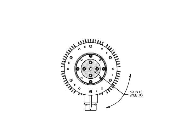
14 Trueness of Load: Loads mounted to the CLD motor must to be mounted so the forces and motion are in line with the shaft. The CLD motor is not designed for offset loads that can cause additional loading or binding of the bearings. Load -B- CL MOTION A -A- B Overhung Loads: The CLD motor is not designed for overhung loads greater than 25 lbs. Overhung loads cause additional and unpredictable bearing wear. Load 25 Lbs Max. Force Shaft Rotation: Shaft rotation is only limited by the feedback device and load constraints. The CLD motor shaft has nothing preventing it from rotating. If shaft rotation is not acceptable, provisions need to be taken to prevent the shaft from rotating. UM Revision A

15 UM Revision A
16 6. Electrical Connections: Control component and system manufacturers use differing nomenclatures in their wiring conventions. When inserting the CLD motor into a system, be sure to consider this, and carefully examine the CLD conventions and those of the control system manufacturer to ensure proper compatibility. Where applicable, CLD follows conventions established in NEMA ICS 16 and ICS 17 ( ICS 17 is presently being written). Motor current and Motor power need to be limited by the amplifier or drive to not exceed the ratings given by individual specification sheets. Thermal cutout should be employed by the system to ensure that motor does not exceed the maximum rated temperature of the motor. Note: It is important to use good grounding and shielding practices for any servo systems that use this motor to minimize electrical interference Motor Drives: CLD motors require a motor drive system to control the position of the motor. The motors are designed for use with drives powered by 240 V 3ø power. Use sinusoidal servo amplifiers or drives with the CLD motor. The servo drive system should be selected and specified to match the specific application. WARNING: Do not use drives powered by voltages greater that 240 VAC Motor Power Connections: It is recommended that a CLD Motor Power Cable be used to connect the motor to the power amplifier or drive. CLD power cables have integrated the necessary power components, connectors and shielding to make a good electrical power connection to the motor. CLD produces a 10 ft. motor power cable (MPC-XX-10-1) and a 25ft motor power cable (MPC-XX-25-1) for use with CLD 4000 and 5000 series motors. Note: If cable lengths greater than 25 ft. are needed, additional voltage spike suppression and special cable design will be necessary. UM Revision A
17 MOTOR FILTER DRIVE A B C CABLE PHASE A A N B PHASE C C PHASE B D Power Filter: A common mode choke should be used in series with the motor power leads. This choke will help minimize ground currents associated with PWM amplifiers and drives. The choke presents a high impedance on to capacitively-coupled ground currents from the PWM transitions. The Choke should be placed within 6 inches of the amplifier or drive lugs. These chokes are supplied on CLD motor power cables Temperature Levels: CLD motors are equipped with temperature sensors to signal the control system when the motor has reached its maximum rated temperature preventing permanent damage to the motor. This motor has no other mechanism that will shut down the motor in the event of over heating. Ensure proper use of the Thermal Protection Sensors with the control system Thermal Protection (AD590): The CLD motor s temperature sensor is an Analog Devices AD590 integrated circuit temperature transducer. The AD590 is a terminal IC that provides an output current proportional to absolute temperature (i.e., the Kelvin scale). This device functions as a high impedance current source. UM Revision A
18 The end user will typically provide a fixed voltage source rated at anywhere from 4VDC to 30VDC, and a 10kΩ resistor. The device functions essentially the same at 4V as it does at 30V, thus providing a large degree of flexibility based on the user s available power source. The CLD linear motor uses two AD590 sensors, one at either end of the motor. Connecting the two sensors as shown in the diagram, allows the two sensed temperatures to be measured. The AD590 simply provides 1 µa/kelvin. Therefore, 25 C ( = 298.2K), should give you 298µA (about 0.3 ma). When the 10kΩ resistor is incorporated as in the figure, the 0.3 ma found at room temperature drives the 10k resistor, giving you a voltage drop across the resistor of 3 volts (0.3mA 10kΩ = 3 V). The Table shows what the user can expect to measure across the 10k resistor of figure as winding temperature increases. The maximum temperature that the sensor should reach is 95 C. In applications where the motor is rapidly climbing in temperature (>5 C/min.) the set point should be lowered by 20 C. Motor (winding) temperature and V T Celsius Fahrenheit Kelvin AD590 output (microamps) V T output VDC UM Revision A
19 TEMP SENSOR CONNECTOR END OF MOTOR SUPPLY 5-30VDC RED + AD590JH ANALOG INPUT TO CONTROL SYSTEM BLACK - 10 KW 0VDC TEMP SENSOR OPPOSITE CONNECTOR END OF MOTOR SUPPLY 5-30VDC WHITE + AD590JH ANALOG INPUT TO CONTROL SYSTEM GREEN - 10 KW 0VDC UM Revision A
20 References: AD590 data sheet, Analog Devices: or Filtering the V T signal A filtering algorithm is typically required to prevent false trips due to noise. One method of filtering is to simply look at the time averaged V T value, and to disable the driver when the average value of V T (over 5 seconds or over some number of servo cycles) exceeds 3.78Vdc. (Example: Use in a servo loop; Vavg=.01(Vin- Vavg)+Vavg ; Start loop with Vavg set to zero) 6.4. Position Feedback: A position feedback signal is required for proper operation of CLD motors. The position feedback signal supplies the control system with the motor s position for control and commutation. Position sensors other than the CLD sensors can be used. The type of position sensor is a system consideration and needs to be determined during system design Using a CLD Position Sensor (optional): CLD produces several position feedback devices for use with its motors: Individual feedback device options have different resolutions, signal types, and compatibility. The Interface Control Drawings for the feedback option contain the relevant information and specifications. [Carefully match the feedback signal types described in the control system manual]. Ensure directionality and commutation compatibility before applying power to the motor Using a 3 rd Party Position Sensor (optional): When using a position sensor other than one supplied by CLD, it is important to meet the following criteria in addition to those determined during system design: Proportional coupling between motor linear position and output signal. A means of commutating the motor. Tight mechanical coupling between the sensor, motor shaft and motor Grounding and Shielding: It is important that the motor and interconnection cables are well-grounded and shielded. The motor grounding should be to a central system ground as well as to the amp and controller. The motor power cable also needs to be shielded and attached to the central ground. UM Revision A
21 CAUTION: Poor ground or shield connections or wiring can cause unpredictable motion, and could damage the motor, control system or machine. 3 Phase Power + Ground P 1 Amp Power Motor Power Cable Y Axis Filter Motor Power P 3 Control AMC Amp. P 2 X Axis Motor 7. Control Conventions: When using the CLD motor in a servo system, specific information always needs to be known and accounted for by the control system. The system always needs to have a directionality reference established, where positive direction or force sensed by the feedback device is commanded by the amplifier and control system. A commutation method with a cycle pitch and reference angle must be established. Many feedback devices supply commutation signals, but if they are devices other than one supplied with the motor, a zero reference angle will have to be established with the control system Directional Reference: For the motor and control system to work properly together, a directional reference will need to be established for the system. CLD motors will generate positive force and motion, and cause the shaft to extend on the power connector side of the motor when the 3 phase wave-form below is applied. UM Revision A
22 Positive Motion Phase to Null EMF DX Shaft Position (in.) Phase A BEMF Phase B BEMF Phase C BEMF Phase Angle (deg.) 7.2. Cycle Pitch: As with other sinusoidal brushless motors, the CLD motor is commutated relative to the shaft position within an electrical cycle. The repetition distance of the cycle is known as the cycle pitch. The cycle pitch on the 4000 and 5000 series motors is.922 inches Commutation Reference: When using a sinusoidal brushless motor without a CLD-supplied commutation feedback device, it is necessary to know the relative shaft position at the start of the electrical cycle. CLD motor documentation is supplied with two reference positions (Q max And X0). Q max is a reference commutation angle with the shaft fully extended in the positive direction. X0 is the distance from last zero degree phase position to the position of maximum positive direction. These values are determined UM Revision A
23 for each motor at the time of manufacture, and are specific for a motor and shaft combination. These values are listed in the documentation supplied with each motor. Shaft in Qmax position Shaft in X0 position 7.4. Tuning a Servo System: The servo system that includes the CLD motor will likely require some form of tuning. Follow the drive and control system manufacturers recommendations for tuning of the system. WARNING: Improper servo tuning can cause uncontrolled motion of the CLD motor. Do not allow the system to oscillate during the tuning process, and keep all personnel and body parts away from moving equipment. UM Revision A
24 8. Motor Cooling: Motor cooling is an important facet of the motor s operation. Depending on the load capacity and ambient air temperature, a cooling system may be required. It is important to keep in mind that like any other motor, the CLD motor produces heat when it operates. It must have the opportunity to dissipate this heat or it will eventually overheat and fail. It may dissipate heat through natural convection (natural flow of air), conduction (attaching to a larger cool object), or one of the CLD cooling options. The more heat a motor can dissipate, the cooler the motor will run, and the longer it will last Fan Cooling (option): The CLD motor can be supplied with five fans that force air over the motor and keep it cool. It is important that the fans and the motor are kept clean, and that cool air is allowed to move freely around the motor. Buildup of excessive dirt and debris on the motor s cooling fins will cause the cooling system to work inefficiently and could lead to overheating the motor Fan Interconnections (option): Connect the fan to a 220 VAC single-phase supply for optimum cooling. Fans will run at lower voltages with less than the designed airflow. Follow applicable local wiring codes and regulations for interconnections. 9. Motor Care and Maintenance: It is important to keep the motor clean and free of dirt and chemicals to prevent damage and ensure long motor life. The CLD motor is not designed for wash-down or exposure to most cleaning chemicals. When cleaning the motor, use a clean dry cloth when removing dirt and debris from the motor and shaft Environmental Considerations: The CLD motor is designed for use in an indoor industrial environment. The motor is not designed to be washed down, exposed to weather, corrosive, or abrasive elements. Ambient temperatures should be between 1 C and 30 C (33 F and 85 F). If the motor is to be used in an ambient temperature greater than 30 C (85 F), the motor s power rating will need to be decreased Bearing Replacement: The CLD motor contains replaceable bearings in the event that they wear out or require replacement for other reasons. The bearings are designed in a taper-lock housing with an integrated oil reservoir. CLD supplies bearing replacement kits containing materials needed to replace both BKM2000. Note: Only use bearings contained in the CLD bearing replacement kit for the 4000 and 5000 series motors. UM Revision A
25 9.3. Shaft Care: The exterior of the motor shaft is carbon steel that will corrode if subjected to corrosive agents. Take care in keeping it clean and free of contaminates that could cause corrosion. The shaft should be maintained with a thin film of CLD-specified oil only. In corrosive environments, the motor shaft will need to be protected from elements Shaft Cleaning: The CLD motor shaft is self-lubricated by oil that is contained in a reservoir in the bearing assembly. Additional oil should not need to be applied to the shaft. If the bearing reservoir runs out of oil, the bearing assembly should be replaced. When cleaning the shaft, use a clean rag lightly oiled with Anderol 465. CAUTION: Only use Anderol 465. Other lubricants could break down prematurely and cause permanent damage to the motor. UM Revision A
26 Appendix-A: (Revision History) ECO # Revision Change Date _ 0064 A Initial Release January 3,
Replace your belt, ball screw or rack and pinion mechanism with a simple and economical linear servo motor actuator
 LINEAR SERVO ECONO-SLIDE Ultimate Solution for High Throughput Precision Positioning Replace your belt, ball screw or rack and pinion mechanism with a simple and economical linear servo motor actuator
A6Z OPERATING MANUAL
 A6Z OPERATING MANUAL TABLE OF CONTENTS Introduction... p. 2 Features... p. 2 Description... p. 3 Theory of Operation... p. 3 Installation... p. 4 Electrical Connections... p. 5 Options... p. 6 Warranty.p.
High Frequency SineWave Guardian TM
 High Frequency SineWave Guardian TM 380V 480V INSTALLATION GUIDE FORM: SHF-IG-E REL. January 2018 REV. 002 2018 MTE Corporation High Voltage! Only a qualified electrician can carry out the electrical installation
dv Sentry TM 208V 600V INSTALLATION GUIDE Quick Reference ❶ How to Install Pages 6 14 ❷ Startup/Troubleshooting Pages WARNING
 dv Sentry TM 208V 600V INSTALLATION GUIDE FORM: DVS-IG-E REL. January 2018 REV. 003 2018 MTE Corporation High Voltage! Only a qualified electrician can carry out the electrical installation of this filter.
www. ElectricalPartManuals. com Instruction Bulletin ALTIVAR FLEX58 TRX Adjustable Speed Chassis Drive Controllers Installation Guide
 Instruction Bulletin ALTIVAR FLEX58 TRX Adjustable Speed Chassis Drive Controllers Installation Guide Retain for future use. 30072-450-47A July 2002 Raleigh, NC, USA HAZARDOUS VOLTAGE Read and understand
Quality Since 1980 SERVICE GUIDE. Eliminator Series HD, HDL, HDR, SD EDrive Actuators, Inc. #FB6070 Linear Actuators
 Quality Since 1980 SERVICE GUIDE Eliminator Series HD, HDL, HDR, SD 2018 EDrive Actuators, Inc. #FB6070 Linear Actuators Contents Important Information for Users 3 Product Description 3 Safety Considerations
Matrix APAX. 380V-415V 50Hz TECHNICAL REFERENCE MANUAL
 Matrix APAX 380V-415V 50Hz TECHNICAL REFERENCE MANUAL WARNING High Voltage! Only a qualified electrician can carry out the electrical installation of this filter. Quick Reference ❶ Performance Data Pages
5001TCP SPEED CONTROLLER
 VARIABLE SPEED DRIVE CONTROLLER INSTALLATION AND SETTING UP MANUAL 5001TCP SPEED CONTROLLER With PC101 Torque Limit Control WARNING Disconnect all incoming power before working on this equipment. Follow
5001TCP SPEED CONTROLLER
 INSTALLATION AND SETTING UP MANUAL 5001TCP SPEED CONTROLLER WARNING Disconnect all incoming power before working on this equipment. Follow power lockout procedures. Use extreme caution around electrical
A3Z OPERATING MANUAL
 A3Z OPERATING MANUAL TABLE OF CONTENTS Introduction... p. 2 Features... p. 2 Description... p. 3 Theory of Operation... p. 3 Installation... p. 4 Electrical Connections... p. 5 Options... p. 6 Warranty...
INSTRUCTION MANUAL FOR VOLTAGE REGULATOR APR P/N
 INSTRUCTION MANUAL FOR VOLTAGE REGULATOR APR 125-5 P/N 9168800100 Publication: 9168800990 Revision: J 03/09 INTRODUCTION This instruction manual provides information about the operation and installation
REFERENCE MANUAL FORM: MX-TRM-E REL REV MTE
 Matrix APAX 380V-415V 50Hz TECHNICAL REFERENCE MANUAL FORM: MX-TRM-E REL. September 2014 REV. 002 2014 MTE Corporation WARNING High Voltage! Only a qualified electrician can carry out the electrical installation
INTRODUCTION WARNING SIGNS AND THEIR MEANINGS
 INTRODUCTION FMI-series frameless motors by Rozum Robotics are designed to provide motion as part of a motion system. Available in a range of sizes (stator dia. 41, 51, 75 mm), FMI motors are suitable
ANDCO Eagle Actuator Instruction Manual
 ANDCO Actuators ANDCO Eagle Actuator Instruction Manual The information contained in this manual is essential to safe, successful, long term operation of your Andco Eagle Linear Actuator. Read and follow
F-4600 INLINE ULTRASONIC FLOW METER Installation and Operation Guide
 F-4600 INLINE ULTRASONIC FLOW METER Installation and Operation Guide 11451 Belcher Road South, Largo, FL 33773 USA Tel +1 (727) 447-6140 Fax +1 (727) 442-5699 1054-7 / 34405 www.onicon.com sales@onicon.com
SM-1000 SERIES ROTARY ACTUATORS
 SM-1000 SERIES ROTARY ACTUATORS GENERAL DESCRIPTION The SM-1000 Series are multi-turn, rotary actuators, designed to meet the exacting requirements for closed-loop modulating positioning control. Designed
MODEL ELC-12/60-D BATTERY CHARGER
 *32198* NATIONAL RAILWAY SUPPLY Installing, Operating and Service Instructions for the 12/60 Solid State Charger MODEL ELC-12/60-D BATTERY CHARGER PLEASE SAVE THESE IMPORTANT SAFETY AND OPERATING INSTRUCTIONS
BOLT-ON AND WELD-ON FLUSH FLOOR SLIDEOUT SYSTEMS OPERATION AND SERVICE MANUAL
 BOLT-ON AND WELD-ON FLUSH FLOOR SLIDEOUT SYSTEMS OPERATION AND SERVICE MANUAL TABLE OF CONTENTS SYSTEM...... Warning........ Description...... Prior to Operation OPERATION... Main Components... Mechanical...
Sofa Slideout Assembly OWNER'S MANUAL. Rev: Page 1 Sofa Slideout Owners Manual
 Sofa Slideout Assembly OWNER'S MANUAL Rev: 06.14.2016 Page 1 Sofa Slideout Owners Manual TABLE OF CONTENTS Warning, Safety, and System Requirement Information 3 Product Information 3 Prior to Operation
12 Series Linear Actuators. Operation & Maintenance Manual, Analog Positioner Installation
 12 Series Linear Actuators Operation & Maintenance Manual, Analog Positioner Installation 6810 POWERLINE DR.-FLORENCE, KY. 41042 - TELEPHONE 859-727-7890, TOLL FREE 1-800-662-9424 FAX. 859-727-4070, E-MAIL:
Below, you can see the warning symbols used throughout the manual and their meaning.
 FMI60201 Frameless motors INTRODUCTION FMI-series frameless motors by Rozum Robotics are designed to provide motion as part of a motion system. Available in a range of sizes (dia. 40, 50, 60, 75 mm), FMI
A1P OPERATING MANUAL
 A1P OPERATING MANUAL TABLE OF CONTENTS Introduction... p. 2 Features... p. 2 Description... p. 3 Theory of Operation... p. 3 Installation... p. 4 Electrical Connections... p. 5 Options... p. 6 Warranty...
MODEL ELC-12/40-CVM-D BATTERY CHARGER
 NATIONAL RAILWAY SUPPLY MODEL ELC-12/40-CVM-D BATTERY CHARGER Installing, Operating and Service Instructions for the ELC-12/40-CVM-D Solid State Charger PLEASE SAVE THESE IMPORTANT SAFETY AND OPERATING
Full View Flow Indicator
 Full View Flow Indicator Threaded and Flanged Process Connection Installation / Operation / Maintenance Manual P.O. Box 1116 Twinsburg, OH 44087 Phone: 330/405-3040 Fax: 330/405-3070 E-mail: view@ljstar.com
INSTRUCTION MANUAL 234 FLOW METER/TRANSMITTER
 INSTRUCTION MANUAL 234 FLOW METER/TRANSMITTER TABLE OF CONTENTS General Description... Pg 2 Specifications... Pg 3 Mechanical Installation... Pg 4-5 Electronic Installation... Pg 6-12 Do s and Don ts...
IRT 4000 AT-S/M/L. Technical Manual. quality IN MOTION. quality IN MOTION
 IRT quality IN MOTION www.irtsa.com 4000 AT-S/M/L Technical Manual IRT quality IN MOTION E2 0 8 4 1 5 September 2013-Rev. 5 UL Requirements Drives Series 2000 / 4000 AT 1. Field wiring terminal to use
Wind Direction Vane. Z345. Installation Guide.
 Wind Direction Vane. Z345 Installation Guide. Wind Direction Vane Installation Guide Index. Description. 3 Features. 3 Ordering Information. 3 Specifications. 3 Product Liability. 3 Connection & Wiring.
SineWave Guardian TM 380V 600V INSTALLATION GUIDE. Quick Reference. ❶ How to Install Pages 6 17 ❷ Startup/Troubleshooting Pages WARNING
 SineWave Guardian TM 380V 600V INSTALLATION GUIDE FORM: SWG-IG-E REL. October 2018 REV. 003 2018 MTE Corporation High Voltage! Only a qualified electrician can carry out the electrical installation of
CHAPTER 6 INTRODUCTION TO MOTORS AND GENERATORS
 CHAPTER 6 INTRODUCTION TO MOTORS AND GENERATORS Objective Describe the necessary conditions for motor and generator operation. Calculate the force on a conductor carrying current in the presence of the
X100P Load Bank. Read all instructions before using the load bank. Contents
 X100P Load Bank Read all instructions before using the load bank Contents 1. Components... 3 Total Assembly... 3 2) Specifications... 4 a) X100P Load Bank... 4 3) Receiving... 4 4) Safety... 5 a) Grounding...
17429X.00 SERIES MODELS:
 LEESON ELECTRIC MOTORS, GEARMOTORS AND DRIVES R User s Manual 17429X.00 SERIES MODELS: 174298.00 174299.00 PWM REGENERATIVE DC TO DC DRIVES II Table of Contents 17429X.00 Drives...............................................................
MDCKB VAC, 8A Brushless Controller. User s Guide E. Landon Drive Anaheim, CA
 MDCKB1-120081-01 110VAC, 8A Brushless Controller User s Guide A N A H E I M A U T O M A T I O N 4985 E. Landon Drive Anaheim, CA 92807 e-mail: info@anaheimautomation.com (714) 992-6990 fax: (714) 992-0471
S-SERIES DISPLACEMENT TRANSDUCERS
 user manual S-SERIES DISPLACEMENT TRANSDUCERS Index Section Title Page 1.0 Introduction.................. 3 2.0 Installation................... 4 2.1 Mounting the Transducer........ 4 2.2 Cores.......................
Embedded Rack Slide-out System
 Embedded Rack Slide-out System SERVICE MANUAL Rev: 02.16.2017 Page 1 Electric Embedded Rack Slide-out System TABLE OF CONTENTS Safety Information 3 Product Information 3 Operation 4 Extending Slide-Out
958A Embedded Linear Displacement Transducer. THEINSIDER the most trusted information comes from INSIDE
 958A Embedded Linear Displacement Transducer THEINSIDER the most trusted information comes from INSIDE The Need for Automation is Greater Today Than Ever Before LINEAR DISPLACEMENT TRANSDUCERS (LDTs) play
Weatherproof Tubular Slip Ring Assembly
 Weatherproof Tubular Slip Ring Assembly Model B8-4.3W 8 circuit weatherproof slip ring Compact design Mounts on shafts up to 4.3 [109.2 mm] in diameter Permanently lubricated bearings Rugged stainless
Hydro-Sync Slide-Out System
 Hydro-Sync Slide-Out System SERVICE MANUAL Rev: 08.14.2018 Hydro-Sync Slide-out System Service Manual TABLE OF CONTENTS Safety Information 3 Product Information 3 Operation 4 Extending Slide-Out Room 4
SERVO MOTORS BRUSHLESS SERVO MOTORS OPERATING INSTRUCTIONS 2016
 SERVO MOTORS BRUSHLESS SERVO MOTORS OPERATING INSTRUCTIONS 2016 3009/16 en Ed.02.2016 Read these Operating Instructions before performing any transportation, installation, commissioning, maintenance or
1100 Series Piston Type Differential Pressure Gauges
 1100 Series Piston Type Differential Pressure Gauges 1. Safety Before installing, check the Series Number and verify compatibility to the process media and temperature in contact with the wetted parts.
Observe all necessary safety precautions when controlling the soft starter remotely. Alert personnel that machinery may start without warning.
 Introduction OPERATING INSTRUCTIONS: MCD REMOTE OPERATOR Order Codes: 175G94 (for MCD 2) 175G361 + 175G9 (for MCD 5) 175G361 (for MCD 3) 1. Introduction 1.1. Important User Information Observe all necessary
ACC Series Power Conditioner OPERATION & INSTALLATION MANUAL
 ACC Series Power Conditioner OPERATION & INSTALLATION MANUAL PHASETEC digital power conditioners are designed to safely operate electrical equipment in the harshest power quality environments. With a wide
PowerOhm Installation Manual for LG ATV Series Braking Modules
 PowerOhm Installation Manual for LG ATV Series Braking Modules IMPORTANT: These instructions should be read thoroughly before installation. All warnings and precautions should be observed for both personal
User s Manual. Automatic Switch-Mode Battery Charger
 User s Manual Automatic Switch-Mode Battery Charger IMPORTANT Read, understand, and follow these safety rules and operating instructions before using this battery charger. Only authorized and trained service
Displacement Sensor. Model 8739, 8740, 8741
 w Technical Product Information Displacement Sensor 1. Introduction... 2 2. Preparations for use... 2 2.1 Unpacking... 2 2.2 Grounding and potential connection... 2 2.3 Storage... 2 3. Principle of operation...
M T E C o r p o r a t i o n. dv/dt Filter. Series A VAC USER MANUAL PART NO. INSTR REL MTE Corporation
 M T E C o r p o r a t i o n dv/dt Filter Series A 440-600 VAC USER MANUAL PART NO. INSTR - 019 REL. 041119 2004 MTE Corporation IMPORTANT USER INFORMATION NOTICE The MTE Corporation dv/dt Filter is designed
2
 Brushless DC motors 2 3 VFD VS ECM(PM Motors) Both take AC and convert to DC VFD is generally 3Ø ECM 1Ø in 3Ø out VFD & ECM Both have Rectifiers VFD & ECM both have transistor outputs VFD Out put
TORQUE TRANSDUCER TMHFB-*NM (for Torque Transducer) Instruction Manual. MinebeaMitsumi Inc. Sensing Device Business Unit
 Instruction Manual. MinebeaMitsumi Inc. Sensing Device Business Unit") TORQUE TRANSDUCER TMHFB-*NM (for Torque Transducer) Instruction Manual MinebeaMitsumi Inc. Sensing Device Business Unit Please read this manual thoroughly before attempting to use the equipment. Be sure
TORQUE TRANSDUCER TMHFB-*NM (for Torque Transducer) Instruction Manual MinebeaMitsumi Inc. Sensing Device Business Unit Please read this manual thoroughly before attempting to use the equipment. Be sure
Note 8. Electric Actuators
 Note 8 Electric Actuators Department of Mechanical Engineering, University Of Saskatchewan, 57 Campus Drive, Saskatoon, SK S7N 5A9, Canada 1 1. Introduction In a typical closed-loop, or feedback, control
AD592/592-10K Non-Room Sensors in BAPI-Box, BAPI-Box 2 or BAPI-Box 4 BA/592-x-(BB, BB2, BB4) Temperature Sensor Instructions & Operation
 Temperature Sensor Instructions & Operation") 592 Theory of Operation The 592 sensor is a two terminal integrated-circuit temperature sensor. The 592 provides an output current directly proportional to absolute temperature. When the temperature of
592 Theory of Operation The 592 sensor is a two terminal integrated-circuit temperature sensor. The 592 provides an output current directly proportional to absolute temperature. When the temperature of
COOKSON OWNER S MANUAL
 COOKSON OWNER S MANUAL ELECTRIC CLUTCH RELEASE FOR TUBULAR MOTOR 3117(1) ECN 0951 BY RG 10/28/10 1 PATENT NO. 6,155,324 SPECIFICATIONS ELECTRICAL SPECIFICATIONS TUBULAR MOTOR FOR TUBULAR MOTOR ELECTRICAL
LN3 Series Motor and Drives
 LN3 Series Motor and Drives Operator's Manual PN 04-01906 C PRECISION MOTION CONTROLS 2175 De La Cruz Blvd. #1 Santa Clara, CA 95050 LN3 Manual CONTENTS Introduction... 3 Description... 3 Features... 3
RHINO MOTION CONTROLS
 Installation Manual and Datasheet http://www.rhinomotioncontrols.com Page 1 [] Key Features Smooth and quiet operation at all speeds and extremely low motor heating Industrial grade performance for 2-Phase
AC Electric Capstan Owner s Manual Installation and Operating Instructions
 AC Electric Capstan Owner s Manual Installation and Operating Instructions Model: HD2000-1A34-F-01 Serial Number: 123456 VAC _ Ø Hz Line Size: 1/2 CAUTION The final determination as to the suitability
INSTRUCTION MANUAL FOR. VOLTAGE REGULATOR Model: APR Part Number:
 INSTRUCTION MANUAL FOR VOLTAGE REGULATOR Model: APR 125-5 Part Number: 9 1688 00 100 Publication Number: 9 1688 00 990 Revision H: 07/2001 CONTENTS SECTION 1 GENERAL INFORMATION...1-1 DESCRIPTION... 1-1
How to: Test & Evaluate Motors in Your Application
 How to: Test & Evaluate Motors in Your Application Table of Contents 1 INTRODUCTION... 1 2 UNDERSTANDING THE APPLICATION INPUT... 1 2.1 Input Power... 2 2.2 Load & Speed... 3 2.2.1 Starting Torque... 3
STR3. Step Motor Drive. User Manual
 STR3 Step Motor Drive User Manual Contents 1 Introduction... 3 1.1 Overview... 3 1.2 Features... 3 1.3 Block Diagram... 4 1.4 Safety Instructions... 5 2 Getting Started... 6 2.1 Mounting Hardware... 6
INSTRUCTION MANUAL 272-5X5 ANALOG TRANSMITTER (210 SERIES FLOW METERS) 272-5X7 ANALOG TRANSMITTER (220/240 SERIES FLOW METERS)
 272-5X7 ANALOG TRANSMITTER (220/240 SERIES FLOW METERS)") INSTRUCTION MANUAL 272-5X5 ANALOG TRANSMITTER (210 SERIES FLOW METERS) 272-5X7 ANALOG TRANSMITTER (220/240 SERIES FLOW METERS) 272-5X8 BIDIRECTIONAL TRANSMITTER (210/240 SERIES FLOW METERS) TABLE OF CONTENTS
INSTRUCTION MANUAL 272-5X5 ANALOG TRANSMITTER (210 SERIES FLOW METERS) 272-5X7 ANALOG TRANSMITTER (220/240 SERIES FLOW METERS) 272-5X8 BIDIRECTIONAL TRANSMITTER (210/240 SERIES FLOW METERS) TABLE OF CONTENTS
SB 2000 PUSH TO SEARCH NEXT STAG E. Aerotech, Inc. FORM: QM 1320
 Inlet Controller SB 2000 USER'S MANUAL AUTO OPEN MANUAL PUSH TO SEARCH NEXT STAG E CLOSE Aerotech, Inc. FORM: QM 1320 4215 Legion Dr. Mason, MI 48854-1036 USA Rev. 3, Sept. 1997 Ph. (517) 676-7070 Fax
TERMINATOR User Manual
 TERMINATOR User Manual TERMINATOR User Manual Table of Contents Section Page 1 2 3 4 5 6 7 8 9 10 11 12 13 14 15 16 17 18 19 20 21 Introduction Safety Precautions Features and Benefits Overview of the
MDCKB VAC, 8A Brushless Controller. User s Guide E. Landon Drive Anaheim, CA
 MDCKB1-120081 120VAC, 8A Brushless Controller User s Guide A N A H E I M A U T O M A T I O N 4985 E. Landon Drive Anaheim, CA 92807 e-mail: info@anaheimautomation.com (714) 992-6990 fax: (714) 992-0471
RE-PR1-F 1-Phase Din-Rail Mount 1.5, 3 & 6kW
 Page 1 of 5 RE-PR1-F 1-Phase Din-Rail Mount 1.5, 3 & Features: Benefits: 0-10Vdc or 0-5Vdc control input Over temperature protection with auto reset Din-rail mounting Efficient electronic switching No
MODEL 1100 TURBINE FLOW METER
 MODEL 1100 TURBINE FLOW METER INSTALLATION & INSTRUCTION MANUAL 8635 Washington Ave. Racine, Wisconsin 53406 Phone: 800.433.5263 Fax: 800.245.3569 www.hedland.com 2 OPERATIONAL START-UP Fluid entering
PerfectSpeed NEMA 48 Pump Motor. With User Interface
 PerfectSpeed NEMA 48 Pump Motor With User Interface Table of Contents Section 1 - PerfectSpeed Motor... 1 Important Safety Information...1 Overview...3 PerfectSpeed User Interface Box...4 Minimum and Maximum
BLY17MDA Series. 24V, 10A Brushless Controller/Motor. User s Guide E. Landon Drive Anaheim, CA
 BLY17MDA Series 24V, 10A Brushless Controller/Motor User s Guide A N A H E I M A U T O M A T I O N 4985 E. Landon Drive Anaheim, CA 92807 e-mail: info@anaheimautomation.com (714) 992-6990 fax: (714) 992-0471
MDC VAC Input Brushless Controller. User s Guide E. Landon Drive Anaheim, CA
 MDC2-2451 11VAC Input Brushless Controller User s Guide A N A H E I M A U T O M A T I O N 4985 E. Landon Drive Anaheim, CA 9287 e-mail: info@anaheimautomation.com (714) 992-699 fax: (714) 992-471 website:
& HIGH CURRENT DC POWER SUPPLIES INSTRUCTION MANUAL
 72-6850 & 72-6852 HIGH CURRENT DC POWER SUPPLIES INSTRUCTION MANUAL Table of Contents Introduction 2 Specification 2 Safety 4 EMC 5 Installation 6 Connections 6 Operation 7 Maintenance and Repair 8 www.tenma.com
BSC Series
 BSC151-024031 Series 24V, 3A Brushless Speed Controller User s Guide A N A H E I M A U T O M A T I O N 910 East Orangefair Lane, Anaheim, CA 92801 e-mail: info@anaheimautomation.com (714) 992-6990 fax:
SE-3SCR-LM MANUAL MOTOR LOAD MANAGER
 3714 Kinnear Place Saskatoon, SK Canada S7P 0A6 Ph: (306) 373-5505 Fx: (306) 374-2245 www.littelfuse.com/relayscontrols SE-3SCR-LM MANUAL MOTOR LOAD MANAGER MARCH 5, 2013 REVISION 4 MOTOR LOAD MANAGER
Pulse Encoder Interface Kit For Use With FlexPak 3000 and WebPak 3000 DC Drives M/N 907FK0101
 Pulse Encoder Interface Kit For Use With FlexPak 3000 and WebPak 3000 DC Drives M/N 907FK0101 Instruction Manual D2-3302-3 The information in this manual is subject to change without notice. Throughout
958A Compact. Series 958 Compact Housing LDT. Housing ABSOLUTE PROCESS CONTROL KNOW WHERE YOU ARE... REGARDLESS
 Series 958 Compact Housing LDT Compact Housing Linear Displacement Transducer Installation Manual 958A Compact Housing ABSOLUTE PROCESS CONTROL KNOW WHERE YOU ARE... REGARDLESS Contents Chapter 1: 958A
Master & Slave SCRs. SCRs for 1 or 3 Phases Nominal Current Max Voltage Slave (Pulse Input) Master (Analog Input) 901-E included Series (SCR)
 Master (Analog Input) 901-E included Series (SCR)") Product Data 95-M & 95-S Series Master & Slave SCRs 95 Series SCR s are available in two configurations. The Master SCR is inclusive of a 95-M (M Suffix) Series Interface which is capable of directly accepting
Product Data 95-M & 95-S Series Master & Slave SCRs 95 Series SCR s are available in two configurations. The Master SCR is inclusive of a 95-M (M Suffix) Series Interface which is capable of directly accepting
Surepowr Series 100 Installation Manual
 Surepowr Series 100 Installation Manual Safety First In the maintenance and operation of mechanical equipment, safety is the basic factor which must be considered at all times. Through the use of the proper
EDB6032_G/GB Antriebstechnik. Operating Instructions. Brake chopper 6032/6033/6034
 EDB6032_G/GB 00376698 Antriebstechnik Operating Instructions Brake chopper 6032/6033/6034 These operating instructions are valid for the devices with the nameplate data: 6032_G.2E 6033_G.2E 6034_G.1A Type
SERIES G3DB/AG3DB ELEVATOR
 TM INSTRUCTIONS AND PARTS LIST SERIES G3DB/AG3DB ELEVATOR WARNING This manual, and GENERAL INSTRUCTIONS MANUAL, CA-1, should be read thoroughly prior to pump installation, operation or maintenance. SRM00059
5000/6000 SERIES BALL VALVES INSTALLATION - MAINTENANCE MANUAL
 Date: August 2011 / Page 1 of 6 5000/6000 SERIES BALL VALVES INSTALLATION - MAINTENANCE MANUAL DESIGN The design features three piece construction and a free floating ball allowing ease of maintenance
Data Bulletin. ALTIVAR FLEX58 Chassis Drive Controllers Class 8806 INTRODUCTION DESIGN CONCEPT. Bulletin No. 8806DB0102 August 2001 Raleigh, NC, USA
 Data Bulletin Raleigh, NC, USA ALTIVAR FLEX58 Chassis Drive Controllers Class 8806 INTRODUCTION The ALTIVAR FLEX58 chassis drive controller offers OEMs, panel builders, integrators, and users a unique
LMCB24-SR LMCB24-SR-T. applications. Dimensions (All numbers in brackets are in millimeters.) 1/4 to 3/4 [6 to 20] 5/16 to 3/4 [8 to 26] 1.
![LMCB24-SR LMCB24-SR-T. applications. Dimensions (All numbers in brackets are in millimeters.) 1/4 to 3/4 [6 to 20] 5/16 to 3/4 [8 to 26] 1.](/thumbs/95/124319282.jpg "LMCB24-SR LMCB24-SR-T. applications. Dimensions (All numbers in brackets are in millimeters.) 1/4 to 3/4 [6 to 20] 5/16 to 3/4 [8 to 26] 1.") LMCB4-SR (-T) Proportional Control, Non-Spring Return, Direct Coupled, 4V, for to 0 VDC and 4 to 0 ma Torque min. 45 in-lb for control of damper surfaces up to sq ft. LMCB4-SR LMCB4-SR-T HALOMO Brushless
LMCB4-SR (-T) Proportional Control, Non-Spring Return, Direct Coupled, 4V, for to 0 VDC and 4 to 0 ma Torque min. 45 in-lb for control of damper surfaces up to sq ft. LMCB4-SR LMCB4-SR-T HALOMO Brushless
AD592/592-10K Non-Room Units with a Junction Box, Weatherproof (WP) or Weather Tight (EU) Enclosure
 or Weather Tight (EU) Enclosure") 592 Theory of Operation The 592 sensor is a two terminal integrated-circuit temperature sensor. The 592 provides an output current directly proportional to absolute temperature. When the temperature of
592 Theory of Operation The 592 sensor is a two terminal integrated-circuit temperature sensor. The 592 provides an output current directly proportional to absolute temperature. When the temperature of
gskin Instruction Manual gskin Heat Flux Sensors for greenteg AG Technoparkstrasse 1 greenteg.com
 gskin Instruction Manual for gskin Heat Flux Sensors 2 / 16 gskin Heat Flux Sensors: Instruction Manual CONTENT 1. SHORT USER GUIDE... 4 2. gskin HEAT FLUX SENSOR INTRODUCTION... 5 3. FUNCTIONALITY TEST...
Chapter 5 FOUNDATION. 2010, The McGraw-Hill Companies, Inc. 2010, The McGraw-Hill Companies, Inc.
 Chapter 5 FOUNDATION 1 FOUNDATION - A rigid foundation is essential for minimum vibration and proper alignment between motor and load. Concrete makes the best foundation, particularly for large motors
Features IN THIS CHAPTER
 CHAPTER THREE 3Special Features IN THIS CHAPTER Motor Braking Regeneration Solutions Sharing the Power Bus: V Bus+ and V Bus- Current Foldback (I T Limit) Front Panel Test Points Resolver Alignment ➂ Special
DMC mA Positioner
 DMC-100 4-20mA Positioner TELEPHONE: +1-859-727-7890 TOLL FREE: +1-800-662-9424 FAX: +1-859-727-4070 E-MAIL: DVOGES@INDELAC.COM MROBINSON@INDELAC.COM TCAYWOOD@INDELAC.COM SHIPPING ADDRESS: 6810 POWERLINE
ENC 150 REFERENCE MANUAL ACU-RITE
 ENC 150 REFERENCE MANUAL ACU-RITE ENC150 Page Introduction... 2 Mounting Preparation... 3 Mounting Information... 4 Encoder Dimensions... 5 Backup Spar Dimensions... 6 Mounting Requirements... 7 Typical
Preparing the Site. Information About the Site Requirements CHAPTER
 2 CHAPTER This chapter describes the basic site requirements that you should be aware of as you prepare to install your Cisco Nexus 7000 Series switches. This chapter includes the following sections: Information
The gear boxes can be run at the same speeds as the actuator models. Do not exceed torque ratings.
 1. What is the lifting torque required? The lifting torque for a single actuator depends on the load, the worm gear ratio, type of screw (machine cut or ball screw) and the pitch of the lifting screw.
VA-908x Series Electric Rotary Actuators for Two-Position and Modulating Service
 VA-908x Series Electric Rotary Actuators for Two-Position and Modulating Service Installation Instructions VA-908x Code No. LIT-12011566 Issued August 24, 2009 Applications The VA-908x Series Electric
MAGNAMAX DVR DIGITAL VOLTAGE REGULATOR
 MAGNAMAX DVR DIGITAL VOLTAGE REGULATOR TECHNICAL MANUAL MODEL DVR 2000 AND DVR 2000C FIGURE 1 - FRONT AND REAR VIEW OF VOLTAGE REGULATOR...4 SECTION 1- INTRODUCTION...5 GENERAL DESCRIPTION...5 SPECIFICATIONS...5
958A Compact Housing Linear Displacement Transducer
 958A Compact Housing Linear Displacement Transducer THEINSIDER the most trusted information comes from INSIDE Simplify Installation and Serviceability The Need for Automation is Greater Today Than Ever
Matrix AP 400V 690V INSTALLATION GUIDE. Quick Reference. ❶ How to Install Pages 6 20 ❷ Startup/Troubleshooting Pages WARNING
 Matrix AP 400V 690V INSTALLATION GUIDE FORM: MAP-IG-E REL. May 2017 REV. 002 2017 MTE Corporation WARNING High Voltage! Only a qualified electrician can carry out the electrical installation of this filter.
Active Controlled Cooling System
 Active Controlled Cooling System April 2011 3267 Progress Dr Orlando, FL 32826 www.apecor.com Preliminary www.apecor.com Table of Contents General Information... 3 Safety... 3 Introduction... 3 What s
NFB24, NFB24-S, NFX24, NFX24-S On/Off, Spring Return, 24 V
 NFB4, NFB4-S, NFX4, NFX4-S On/Off, Spring Return, 4 V Torque min. 90 in-lb, for control of air dampers Technical Data Power supply Power consumption Transformer sizing Electrical connection NFB4... NFX4...
Código de rotor bloqueado Rotor bloqueado, Letra de código. Rotor bloqueado, Letra de código
 Letra de código Código de rotor bloqueado Rotor bloqueado, Letra de código kva / hp kva / hp A 0.00 3.15 L 9.00 10.00 B 3.15 3.55 M 10.00 11.00 C 3.55 4.00 N 11.00 12.50 D 4.00 4.50 P 12.50 14.00 E 4.50
LMX120-SR. Proportional Control, Non-Spring Return, Direct Coupled,100 to 240 VAC, for 2 to 10 VDC and 4 to 20 ma
 LMX0-SR Proportional Control, Non-Spring Return, Direct Coupled,00 to 0 VAC, for to 0 VDC and to 0 ma Torque min. 5 in-lb for control of damper surfaces up to sq ft. Application For proportional modulation
R&S RT-ZC02 R&S RT-ZC03 AC/DC Current Probe User Manual
 R&S RT-ZC02 R&S RT-ZC03 AC/DC Current Probe User Manual / User Manual Content 1 Introduction 3 2 Safety 3 3 Specifications RT-ZC03 6 Specifications RT-ZC02 7 4 Operating Instructions RT-ZC03 8 Operating
LTX RF LEVEL SENSOR. Instruction Manual
 LTX RF LEVEL SENSOR Instruction Manual FOR MODELS LTX01, LTX02, LTX05 Intempco Document No: LTX - M01 Rev. 1 Issue Date: April 2005 LTX01 RF LEVEL SENSOR USER MANUAL Software Rev : Rev. Date : June 2004
BALDOR MN413 Brakes Manual
 BALDOR MN413 Brakes Manual http://www.manuallib.com/baldor/mn413-brakes-manual.html The DODGE D-Series motor brakes are manufactured to NEMA standards for mounting to C-face and double shafted motors.
Tech Note Truck 14 & 15.5 Twin Plate Cast Iron Type Installation Guidelines
 1. (14 & 15.5 ) Check condition of the flywheel. Grind to resurface or replace flywheel. Surface MUST BE machined or premature clutch failure can occur. Flywheel depth must be 2.938 (74.62mm) for 14 (350mm)
Servo and Proportional Valves
 Servo and Proportional Valves Servo and proportional valves are used to precisely control the position or speed of an actuator. The valves are different internally but perform the same function. A servo
2-PHASE STEPPING MOTOR DRIVER FE Z5 DISPENSE
 2-PHASE STEPPING MOTOR DRIVER FE Z5 DISPENSE For Diaphragm Dosing Pumps FEM 1.02_.55 / FEM 1.09_.55 Controller board package, without pump: ID 160536 Operating and Installation Manual It is important to
Application Note CTAN #234
 Application Note CTAN #234 The Application Note is pertinent to the Unidrive SP Family A Guide to Tuning the Unidrive SP Introduction: The Unidrive SP provides a number of features that greatly assist