Hydraulic Proportional and Closed Loop System Design
|
|
|
- Alvin Patterson
- 6 years ago
- Views:
Transcription
1 Hydraulic Proportional and Closed Loop System Design Neal Hanson Product Manager Industrial Valves and Electrohydraulics 1
2 Electrohydraulics Contents 1. Electrohydraulic Principles 2. Proportional Valve Spools Nominal Flows Pressure Drops Power Limits Performance Terms 3. Servo-Solenoid Valves Advantages Differences Application Hints 4. Servo Valves Principles Features 5. Amplifiers Types Optimizing Features 6. Control Systems Valve Selection Closed Loop 7. Updates Resources Other Updates 2


3 Electrohydraulics Proportional Components Operate under electronic control Pressure Relief Pressure Reducing Throttling Flow Control Directional Control Pump Control - Flow - Pressure - HP Limiting 3


4 Electrohydraulics 4 Main Control Principles Force Controlled Solenoid Servo Solenoid Position Controlled Solenoid Servo Valves 4
5 Proportionals Proportional Force Solenoid Solenoid current is proportional to armature force, unlike on/off solenoid This proportional force is linear within a working stroke (approx 1.5 mm) Given a constant current, solenoid force remains constant within the working stroke Coil Force Armature 5
6 Proportionals Proportional Solenoid on a Pressure Relief Solenoid force opposed by pressure P x A (area seat 3) Input to amplifier changes solenoid current (output Force) 20% input => 20% pressure 80% input => 80% pressure 6

 80% input")
7 Proportionals Proportional Solenoid on a Throttle Valve Solenoid force opposed by spring force = rate x displacement Spool position is constant, when forces are balanced Input (coil current) is directly proportional to output force 40% input => 5% flow (due to spool overlap, deadband) 80% input => 50% flow

8 Proportionals Proportional Solenoids on a Directional Valve Solenoid force vs. spring force positions spool Select one solenoid to control direction and flow 40% input Sol-a => 15% flow P-to-B a 80% input Sol-b => 80% flow P-to-A Hysteresis <6 % b a b 8
9 Proportionals Stroke Controlled Solenoid Improve accuracy and performance with position feedback on solenoid LVDT Linear Variable Displacement Transformer Position transducer short stroke High resolution Non-contacting Robust LVDT Armature Sol. Coil 9


10 Proportionals Stroke Controlled Pressure Relief Adding LVDT position feedback greatly improves resolution 0.2% Hysteresis 10

11 Proportionals Stroke Controlled Directional Valve LVDT position feedback improves performance Increased flow capacity Higher Power Limit Better Response Sensitivity Better Hysteresis < 0.3% 11

12 Proportionals Construction of Proportional Valves Proportional spools slide in cast body No sleeve, in main stage (unlike a servo valve) Robust construction similar to on/off directional valves High flow capacity Low cost Throttle area normally formed by notches cut into spool Notch size and geometry determine flow capacity for a given housing 12

13 Proportionals Notch shape determines flow characteristic Square Cut D Cut V Cut Flow Flow Flow Stroke / Command Stroke / Command Stroke / Command 13
 Only 145 psi pressure drop across valve!")
14 Proportionals Nominal Flow Rating of Proportionals Nominal Flow for proportional spools is rated at p = 10 bar (145 psi) total, 5 bar per land Example 4WRA Nominal Flow is 7 to 60 LPM p =10 bar (145 psi ) Only 145 psi pressure drop across valve! This is a not typical for applications Avoid to common mistake: Supersizing spool = poor resolution 72 psi (5 bar) 145 psi (10 bar) 14
15 Proportionals Flow Rating of Proportional Valves Required Flow is normally given, Q req Nominal valve drop p = 10 bar (145 psi) You must estimate pressure drops, p system p load = p valve To find a spool, solve for Nominal flow Estimate required valve pressure drop Q is proportional to square root of corresponding p Q n Q req = c A P n = c A P real c = orifice flow co-efficient A = Area of orifice (same values for both equations) Q nominal = Q req P nominal rating P real valve drop Then, go to valve data sheet and select the closest spool to this value 15
16 Electrohydraulics Using Flow Diagrams Estimate p required across valve in both flow paths, System pressure Load pressure Each housing size may have several spool flow options Find a spool curve that fits the target nominal flow around 90% Command, with a reasonable p, close the your estimated valve p 16
17 Proportionals Can Valve Pressure Drop Be Too High? Yes, valve p over 50% system pressure is high Avoid over-flowing valve! curve 5 High flow forces try to center spool on direct operated proportional valves High p in a proportional valve creates a high rotational force Anti-Rotation design prevents spinning spools, but limit time at extreme conditions to avoid problems Sleeve and Spool valves do not have rotational forces 17
 Bernoulli forces try to center spool at high p v Power Limit decreases if flows are unequal")
18 Proportionals Power Limits All direct operated proportional valves have Power Limits ( Q valve p valve ) Bernoulli forces try to center spool at high p v Power Limit decreases if flows are unequal 18
19 Proportionals Power Limits Power limit diagrams may be plotted in different ways, but they represent the same thing Sometimes performance limits are only listed in a table Volume in L/min Pressure in bar 19
20 Proportionals Common Proportional Spools E-spool: All ports blocked Overlap 10% to 20% on each side Differential cylinder may creep, due to leakage in cylinder and spool Closed loop positioning requires a more advanced controller V-spool: No deadband 1% underlap allows housing variation Only for closed loop control W-spool: 2% to 3% open A to T, B to T Primarily for differential cylinders Only for open loop applications 20
21 Proportionals Asymmetrical Spools Asymmetric spools like E1-, W1-, V1-2:1 flow area (4 notches vs. 2 notches) For differential area cylinders Balances p across each flow path, due to unequal flows to/from cylinder Can prevent cylinder cavitation May improve cycle time - Better deceleration - Shorter reversal time This is more important with larger flow valves 21

22 Proportionals Additional Spool Types W6-spool: improved W-spool - crossover all ports are closed (to stop) - then decompress at center, open 2% A to T and B to T W8-spool: improved W1-spool, like W6 but 2:1 flow area Q2-spool: for injection molding cylinders 22
23 Proportionals Regen Spools with external bypass W3-spool: hydraulic regeneration extends cylinder quickly. Rod side is blocked by B port. High pressure on rod end pushes flow over external check valve - Fast traverse. but rod pressure is high! - Tonnage reduced! Extending force = rod area x pressure bore W9-spool: improved W3 (decel like W8) W3-spool W9-spool W4-spool: 4-position, regen spool - Full tonnage below 33% (P-to-A and P-to-B, like W1) - Regen above 33% (P-to-A and B blocked, like W3) W4-spool 23

24 Proportionals Spools with Internal Regen R-spool: Internal hydraulic regeneration - Combines B to P in spool! - Blocked center, so cylinder could creep R3-spool: Internal regen - connects B-to-P path inside housing - Center P blocked, A and B to T R5-spool: Internal regen with 4-position press-regen spool - P-to-A full tonnage below 33% - Regen above 33% (like R3) Internal regen flow can not exceed limits of main valve (lower flow than external regen) R5-spool 24
25 Proportionals Performance Terms Hysteresis 5% Reversal Error 1% Response Sensitivity 0.5% Hysteresis is max. position error which depends on direction history Reversal Error is the smallest signal that moves spool in the opposite direction Response Sensitivity is the smallest signal to move spool in the same direction, after stopping (resolution of valve) 25
26 Proportionals Performance Terms Repeatability - Ability to achieve the same spool position (or pressure) given the same valve, under the same conditions, with the same command input Force controlled valves: 2% to 3% Stroke controlled: 0.1% to 0.5% Typically half the Hysteresis Question if you need to achieve 100 psi pressure repeatability on a system operating at 5000 psi, should you use a proportional relief valve with a repeatability of 3%? No maximum repeatability is 0.03 x 5000 psi = 150 psi 26
27 Proportionals Step Response Time for spool transition given a stepped input Standard test conditions (fluid temp, pressure) may not match your application If only given a time, you must know measurement criteria 0 to 100% 10 to 90%, 20% to 80% 27
28 Proportionals Bode Diagrams Valve frequency -3dB amplitude Phase -90 degrees -3 db 90 Degrees Phase Lag 28
29 Proportionals Tester for Integrated Electronic Valves VT-VETSY-1-1X/ /USA R Includes 24vdc power supply with US power cord, 2 cables for 7-pin, servo adapter, VET tester 29
30 Servo Solenoid Valves Servo Solenoid Basics 30
31 Servo Solenoid Valves Servo Solenoid Direct Operated Very Fast Stroke Solenoid Directly Positions Spool On Board Electronics No Flapper/Nozzle spring No Jet-pipes No Pilot Leakage Position feedback armature solenoid spool sleeve Spring plate 31
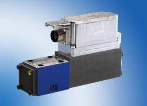
32 Servo Solenoid Valves Servo Solenoid Direct Operated Spool and Sleeve Assembly Zero Overlap Accurate Symmetrical Linear Normal filtration Main sleeve means Nominal p 70 bar or 1000 psi! 2 to 100 Lpm (size 6 & 10) like a Servo 70 bar p 4WRPEH - Direct Operated 32
33 Servo Solenoid Valves Nominal Flow Conversion Easily convert between - Sleeve/Spool rated Nominal psi p - Proportional rated Nominal 145 psi p = 7 Servo to Proportional nominal rating, divide by square root 7 Proportional to Servo nominal rating, multiply by square root 7 33
34 Servo Solenoid Valves Spool/Sleeve in Direct Operated Servo Solenoid Zero overlap matched spool and sleeve Failsafe position with overlap, by spring offset during power off / fault), which may eliminate need for an external blocking valve C5, C1 have 2:1 flow ratios 34
35 Servo Solenoid Valves Servo Solenoid - Direct Operated Smooth cross-over (through center) like Servo, important to Most Reliable OBE Available 25g mechanical shock and vibration for 24 hours in 3 Axis Long Service Life 60 to Deg, small signal Ideal for many closed loop applications 4WRPH6, 4WRPEH6, 4WRPEH10 RE29035, RE
36 Servo Solenoid Valves Fuse OBE on Servo Solenoids Protect each OBE with 2.5 Amp, Fast acting Fuse! 36
37 Servo Solenoid Valves Pilot Operated Servo Solenoid Valves 37
 Nominal Flow rated at 10 bar p for pilot operated")
 allows main spool to spring center 4WRLE RE 29088 RE 29089")
38 Servo Solenoid Valves Servo Solenoid Pilot Operated Main stage has proportional spool in cast housing Pilot stage has sleeve/spool (4WRPEH) Nominal Flow rated at 10 bar p for pilot operated Servo Solenoid valves E, W, V, Q4-spools like proportional V-spool at spring-center has 1 to 6% offset P-to-B Failsafe of pilot (C3) allows main spool to spring center 4WRLE RE RE
39 Servo Solenoid Valves Linear Characteristic V-Spool with Linear flow characteristic can improve system performance Higher P-gain in controller reduces following error Easier tuning of close loop application Standard Flow Curve 4WRLE 10 V55M New Flow Curve 4WRLE 10 V55L 39
40 Servo Solenoid Valves Servo Solenoid Pilot Operated Nominal Flow (Size 10 to 35) 50 to bar or 145 psi p, like a Proportional Main stage has LVDT feedback Many Same Advantages Robust Reliable 4WRLE - Pilot Operated 40
41 Servo Solenoid Valves High Response Servo Solenoid Valves 41
42 Servo Solenoid Valves High Response Servo Solenoid - Direct Op 4WRREH 6: Push-pull, servo solenoid for faster response than 4WRPEH deg, small signal Nearly as fast as 4WS2EM6 Sleeve/spool assembly Nominal Flow 2 to bar p 4WRREH6 RE
43 Servo Solenoid Valves High Response Servo Solenoid - Direct Op Failsafe of spool is not defined Spring centers, but not to a failsafe position 12-Pin Onboard Electronics Enable input Fault output Makes a great pilot valve On Board Electronics 4WRREH6 spool sleeve armature Double solenoid Position feedback 43
44 Servo Solenoid Valves High Response Servo Solenoid - Pilot Op 4WRVE higher dynamics Pilot 4WRREH 6 Main Stage Same as 4WRL 4WRVE 44
 Higher performance Sizes 10 to 25 Only Linear")
45 Servo Solenoid Valves High Response Servo Solenoid - Pilot Op 12-pin Elec. Connector No Failsafe Position (Center main spool with Z4WE6 under pilot) Higher performance Sizes 10 to 25 Only Linear V-spool characteristic available Extremely Reliable OBE 45
46 Servo Valves Servo Valves Basics 46


47 Servo Valves Flapper-Nozzle Servo 47


48 Servo Valves 4WS2EM Servos Servo Valve always has a Sleeve and Spool in Main Stage Servo Torque Motor and Orifices Control Pressure Balance to Position Main Spool Small Signal -90 degrees = 200 to 300 Hz 48 4WS2EM6 RE WS2EM10 RE29583
49 Servo Valves Jet Pipe Servo Not from Bosch Rexroth 49

50 Servo Valves 4WSE3E (16,25, 32) Servo Flows to 1000 Lpm at 70 bar p Sleeve/Spool in main stage Cast body reduces weight & cost Long life with HFC-water glycol, at high pressures Small Signal Response 100 to degrees 4WSE3 RE29620, RE29621, RE
51 Proportional Valves and High Response Valves So Many Proportional and Servo Valves Where do I begin? 51
52 Considerations for Basic Applications Most Important Issues Are Flow Requirement (Easy to Define) - Cycle Time or Desired Actuator Speed - Limits by Pump Flow, HP, Budget Dynamic Performance - Acceleration - Repeatable Deceleration - Fast and Accurate (Productivity) - Especially in Closed Loop Applications - Higher performance normally requires Closed Loop 52
53 Amplifiers Amplifiers Basics for Proportional Valves 53


54 Amplifiers Amplifier Format Different styles for application requirements Modules (rail mount) Plug-in Euro Cards On-Board Electronics Plug Amplifiers 54

 Euro Card analog Ramp Enable")


55 Amplifiers Amplifier Functionality Euro Card digital OBE On-Board Electronics Module Analog (10v or 4-20ma) Euro Card analog Ramp Enable Input Preset Zero Adj Status LED Test Points 4 Presets Analog (10v or 4-20ma) More Ramps Discrete Inputs Status LED Configuration Options Card Holder 16 Presets Software Setup Extended Configuration Options Backup Field bus (optional) 55


56 Amplifiers Amplifier Configuration Flexibility Analog Command Call-ups Analog Command Custome er Signals Analog Command Call-ups Command analog Command digital 56


57 Amplifiers On-Board Electronics Plug & play - No user adjustments required Factory set calibration simplifies installation and replacement 57
58 Amplifiers Plug Amplifiers Plug amplifiers are only possible with single, force solenoids (like a proportional relief valve) M12 electrical connector for simple installation with molded cables Low cost 58


59 Amplifiers Euro Card Amplifiers More features included Match edge connector to correct card holder 59


60 Amplifiers Card Holders Confirm edge connector form required on valve data sheet 32D, 32F, 48F, 64G 60 Bosch
61 Amplifiers Jump Compensation in Amplifier E, W-spools have ±10% to ±20% overlap Jump Compensation reduces this deadband to about ±3 to ±5% 61
62 Amplifiers Characteristic Curve Generator Linearizes valve output Optimized for specific valve type 62

63 Amplifiers Pulse Width Modulation PWM adjusts the average output power to a DC prop. solenoid by switching a fixed DC voltage on-off On vs. Off time varies, within a fixed period PWM frequency is typically 100 Hz to 350 Hz, to minimize hysteresis Frequency must be high enough, so output is not disturbed Normally a factory setting, but some amplifiers permit user adjustment PWM is efficient, reducing heat generation 63
64 Amplifiers Dither Dither is used to create a PWM signal on proportional amplifiers Servo valve amplifiers do not require PWM, so a dither signal (sine wave) adds to the desired DC output Dither frequency is selected to minimize static friction, improving hysteresis 64
65 Amplifiers Amplifier Adjustments Gain Changes input vs. output ratio Limits maximum output Input Zero (Null) Offsets spool into a 0 hydraulic condition due to manufacturing tolerances Input Stroke Stroke 65
66 Amplifiers Amplifier Adjustments Ramp Time Single ramp controls acceleration and deceleration Dual ramps control acceleration (ramp up) separate from deceleration (ramp down) Quadrant ramps change all 4 quadrants independently Input Time 66


67 Amplifiers Amplifier Overview RE29012-V 67
68 Systems Control Valves and Systems 68
69 Closed Loop Applications Closed Loop 69
70 Moving to Closed Loop Closed Loop Structure Closed Loop means automatic regulation of Position Force Pressure Velocity Etc... Command Controller Σ Amplifier Constant correction occurs from error generated Valve Actuator Feedback 70

71 Closed Loop RE Position Control - Engineering Tool Valve Matrix & Project Worksheet (suitable for Hyvos simulation) 71

72 RE Position Control Engineering Tool Valve Matrix 72
73 Closed Loop Hydraulic Response of Cylinder Closed Loop Hydraulic Response Could Be Tested f h = Number of Oscillations per Second T = Time for one cycle (sec) This does not include the Control Valve response The amplitude of oscillation decreases due to Damping (resistance, friction) T f h = 1 T m 73
74 Closed Loop Modeling a Cylinder Closed loop performance depends on valve and cylinder Hydraulic Natural Frequency f h (simplified as a mass-spring model) - C: Spring Constant of Fluid under Compression (fluid on each side of the piston acts like a spring) C - m: Moving Mass f h = m 2π Hydraulic Natural Frequency Hydraulic Mass-Spring Model m 74
75 Closed Loop Modeling a Cylinder System Spring Constant C (Hooke s Law) C = x Displacement of Spring F x Force acting on Spring x = V A F x = p A p = V E V o f h = C m 2π f h = E A 2 V o m 2π Calculations can get complicated Results are only approximate f h = frequency of spring-mass model (hydraulic cylinder) V = Volume change in cylinder A = Area of cylinder (each side) E = Bulk modulus of fluid V o = Volume of trapped fluid m = effective mass 2π radian/sec = 1 Hz 75
76 Closed Loop Modeling a Cylinder and Valve Closed loop response f o depends on valve and cylinder Hydraulic Natural Frequency f h (simplified as a mass-spring model) - C: Spring Constant of Fluid under Compression (fluid on each side of the piston acts like a spring) - m: Moving Mass Valve Frequency Response f v (from data sheet, Bode plot) Hydraulic Natural Frequency f o = f v f h (f v + f h ) Hydraulic Mass-Spring Model m Valve Freq. Response plus Valve Response 76
77 Closed Loop Axis Worksheet Define Customer and Application goals Cylinder Parameters Cylinder Orientation Moving Mass Frictions 77
78 Closed Loop Axis Worksheet Piping Parameters Supply Pressure Opposing Forces or Force Profile 78
79 Closed Loop Axis Worksheet Command Profile Type of Feedback Desired Accuracy Position vs. Time Diagram Desired Velocities Acceleration Limits Desired Cycle Time 79


80 Closed Loop Hyvos simulation analysis For critical designs, use simulation to confirm proper valve selection and system response 80


81 RE 0800 Position Control Engineering Tool Hyvos simulation analysis Collect all relevant machine information (Hyvos worksheet or RE 08200) Your system design should already use much of this information Critical systems can be confirmed by simulation. 81
82 Updates Other Updates 82


83 Update Hydraulic Training 83
84 Update Documentation Resource 84
85 Update Documentation Resource 85
86 Thank You 86
Electro-Proportional Terms and Definitions
 Electro-Proportional Terms and Definitions Valve Deadband The span of operation where there is no flow or pressure output for some specified range of command Hydraulic Valve Gain The characteristic relating
D660 Series Servo-Proportional Control Valves with Integrated Electronics ISO 4401 Size 05 to 10
 D660 Series Servo-Proportional Control Valves with Integrated Electronics ISO 4401 Size 05 to 10 OVERVIEW Section Page MOOG SERVO-PROPORTIONAL CONTROL VALVES Overview 2 3 Technical Data 4 5 Electronics
Directional servo-valve in 4-way design
 Directional servo-valve in 4-way design RE 2983/.11 Replaces: 7.3 1/ Type 4WS.2E... Size Component series X Maximum operating pressure 31 bar Maximum flow 1 l/min HD892 Type 4WSE2ED -X/...K31EV HD893 Type
4/4 directional control valves, direct operated, with electrical position feedback and integrated electronics (OBE)
") 4/4 directional control valves, direct operated, with electrical position feedback and integrated electronics (OBE) Type 4WRPEH RE 29121 Edition: 2014-01 Size 6 Component series 3X Maximum operating pressure
4/4 directional control valves, direct operated, with electrical position feedback and integrated electronics (OBE) Type 4WRPEH RE 29121 Edition: 2014-01 Size 6 Component series 3X Maximum operating pressure
3/3 servo directional control valve with mechanical position feedback
 Courtesy of CMA/Flodyne/Hydradyne Motion Control Hydraulic neumatic Electrical Mechanical () 426-4 www.cmafh.com 3/3 servo directional control valve with mechanical position feedback Type 4WS2EM...XN...-114
D661-G...A Series Servovalve With Bushing and Integrated 24 Volt Electronics ISO 4401 Size 05
 D661-G...A Series Servovalve With Bushing and Integrated 24 Volt Electronics ISO 4401 Size 05 OVERVIEW Section Page MOOG SERVO-PROPORTIONAL CONTROL VALVES Overview 2 3 Technical Data 4 5 Performance Specs.
Servo and Proportional Valves
 Servo and Proportional Valves Servo and proportional valves are used to precisely control the position or speed of an actuator. The valves are different internally but perform the same function. A servo
4-way directional servo valve Type 4WS.2E
 RE 29 91/06.02 Replaces: 03.93 4-way directional servo valve Type 4WS.2E Nominal size 16 Series 2X Maximum operating pressure 2/31 bar Maximum flow 3 L/min Overview of contents Contents Page Features 1
Servo solenoid valves with positive overlap and on-board electronics
 Servo solenoid valves with positive overlap and on-board electronics RE 29089/01.05 1/22 Replaces: 05.04 Type 4WRLE 10...35, symbols E./W. Nominal size 10, 16, 25, 35 Unit series 3X Maximum working pressure
three different ways, so it is important to be aware of how flow is to be specified
 Flow-control valves Flow-control valves include simple s to sophisticated closed-loop electrohydraulic valves that automatically adjust to variations in pressure and temperature. The purpose of flow control
Servo solenoid valves with positive overlap and on-board electronics (OBE)
") Electric Drives and Controls Hydraulics Linear Motion and Assembly Technologies Pneumatics Service Servo solenoid valves with positive overlap and on-board electronics (OBE) RA 2989/1.5 1/24 Model 4WRLE
Electric Drives and Controls Hydraulics Linear Motion and Assembly Technologies Pneumatics Service Servo solenoid valves with positive overlap and on-board electronics (OBE) RA 2989/1.5 1/24 Model 4WRLE
Directional control valves, direct operated, with electrical position feedback and integrated electronics (OBE)
") Directional control valves, direct operated, with electrical position feedback and integrated electronics (OBE) Type 4WRPE RE 29122 Edition: 2014-11 Size 10 Component series 3X Maximum operating pressure
Directional control valves, direct operated, with electrical position feedback and integrated electronics (OBE) Type 4WRPE RE 29122 Edition: 2014-11 Size 10 Component series 3X Maximum operating pressure
Servo solenoid valves with positive overlap Position feedback (Lvdt DC/DC ±10 V)
") Servo solenoid valves with positive overlap Position feedback (Lvdt DC/DC ±10 V) RE 29087/01.05 1/22 Replaces: 05.04 Type 4WRL 10 35, symbols E. / W. Nominal size 10, 16, 25, 35 Unit series 3X Maximum
Servo solenoid valves with positive overlap Position feedback (Lvdt DC/DC ±10 V) RE 29087/01.05 1/22 Replaces: 05.04 Type 4WRL 10 35, symbols E. / W. Nominal size 10, 16, 25, 35 Unit series 3X Maximum
Proportional directional valves, direct operated with electrical position feedback
 aulics PB Bosc exr oth H y d r u l i s G ToBos ch 0011/ ydr R 116 Bosch Rexroth Hydraulics To USH00011/08.2017 To Focused Delivery Program: Proportional Valves Proportional Valves Proportional directional
4-way directional servo-valve
 4-way directional servo-valve RE 29564/09.10 Replaces: 01.07 1/12 Type 4WS.2E Size 6 Component series 2X Maximum operating pressure 315 bar Maximum flow 48 l/min HD5994 Table of contents Contents age Features
10 FT./lbs. TORQUE FOR SOLENOID NUT MANUAL OVERIDE PIN GREY PLUG (85.3) 3.36 (74.7) SOLENOID "a" "B" PORT END (3.2) LOCATING PIN.
 3.36 (74.7) SOLENOID a B PORT END (3.2) LOCATING PIN.") EDM ELECTRICAL OPTIONS: CODES B, BT or BH NFPA D size (former D) For interface pattern see Mounting Surface section. (.).9 SOL. "b" DIMENSIONS SHOWN : (MILLIMETERS) CHES SOL. "a" /- NPTF -P CONNECTOR OPTION
EDM ELECTRICAL OPTIONS: CODES B, BT or BH NFPA D size (former D) For interface pattern see Mounting Surface section. (.).9 SOL. "b" DIMENSIONS SHOWN : (MILLIMETERS) CHES SOL. "a" /- NPTF -P CONNECTOR OPTION
Proportional directional control valve, pilot operated with on-board electronics (OBE) and inductive position transducer
 and inductive position transducer") Proportional directional control valve, pilot operated with on-board electronics (OBE) and inductive position transducer RE 29076/12.05 1/24 Type 4WRBKE Nominal size (NG) 10, 16, 27, 35 Unit series 1X
Proportional directional control valve, pilot operated with on-board electronics (OBE) and inductive position transducer RE 29076/12.05 1/24 Type 4WRBKE Nominal size (NG) 10, 16, 27, 35 Unit series 1X
2-way proportional throttle valve for block installation
 -way proportional throttle valve for block installation RE 90/07.05 Replaces: 03.00 / Types FE; FEE Size 6 Component series X Maximum operating pressure 35 bar Maximum flow 90 L/min bei p = 0 bar H4538
Rexroth Hydraulics. Servo directional valve of 4-way design Type 4WS.2EM RE /03.99
 RE 29 564/03.99 Replaces: 29 563 Servo directional valve of 4-way design ype 4WS.2EM Nominal size 6 Series 2X Maximum operating pressures 210 / 315 bar Maximum flow 40 L/min H//D 5994/98 ype 4WS2EM 6-2X/.E...K17EV
Servo solenoid valves with on-board electronics (OBE)
") Servo solenoid valves with on-board electronics (OBE) RE 29077/01.05 1/16 Replaces: 01.03 Type 4WRVE10...25 Size 10, 16, 25 Unit series 2X Maximum working pressure P, A, B 350 bar, T, X, Y 250 bar Nominal
Servo solenoid valves with on-board electronics (OBE) RE 29077/01.05 1/16 Replaces: 01.03 Type 4WRVE10...25 Size 10, 16, 25 Unit series 2X Maximum working pressure P, A, B 350 bar, T, X, Y 250 bar Nominal
Proportional and Servo Valve Index
 Proportional and Servo Valve Index Proportional and Servo Valves Leading the Way for Intelligent Hydraulics Hydraulic valves which are electrically operated by proportional solenoids are classifi ed as
Appendix A: Motion Control Theory
 Appendix A: Motion Control Theory Objectives The objectives for this appendix are as follows: Learn about valve step response. Show examples and terminology related to valve and system damping. Gain an
Directional servo-valve of 4-way design
 Courtesy of CM/Flodyne/Hydradyne Motion Control Hydraulic Pneumatic Electrical Mechanical (0) 426-54 www.cmafh.com Directional servo-valve of 4-way design Type 4WSE3E 32 Size 32 Component series 5X Maximum
3-way servo solenoid valves, cartridge type, pilot operated, with inductive position transducer
 3-way servo solenoid valves, cartridge type, pilot operated, with inductive position transducer Type 3WRCB 25...50 Nominal size (NG) 25, 32, 50 Unit series 1X Maximum working pressure P, A, T, X, Z 315
4/3 directional control valve, pilot operated, with electric position feedback and integrated electronics (OBE)
") 4/ directional control valve, pilot operated, with electric position feedback and integrated electronics (OBE) RE 977/.1 Replaces: 1.9 1/16 Type 4WRVE 1...7, symbols V, V1 Sizes 1, 16, 5, 7 Component series
4/ directional control valve, pilot operated, with electric position feedback and integrated electronics (OBE) RE 977/.1 Replaces: 1.9 1/16 Type 4WRVE 1...7, symbols V, V1 Sizes 1, 16, 5, 7 Component series
Servo solenoid valves with on-board electronics (OBE)
") Servo solenoid valves with on-board electronics (OBE) RE 29088/01.05 1/18 Replaces: 05.04 Type 4WRLE10...35, symbols V/V1 Size 10, 16, 25, 35 Unit series 3X Maximum working pressure P, A, B 350 bar, T,
Servo solenoid valves with on-board electronics (OBE) RE 29088/01.05 1/18 Replaces: 05.04 Type 4WRLE10...35, symbols V/V1 Size 10, 16, 25, 35 Unit series 3X Maximum working pressure P, A, B 350 bar, T,
4/3-way high response directional control valve pilot operated with electrical feedback and integrated electronics (OBE)
") 4/3-way high response directional control valve pilot operated with electrical feedback and integrated electronics (OE) ype 4WRDE Nominal size to 35 Component series 5X Maximum operating pressure 3 bar
4/3-way high response directional control valve pilot operated with electrical feedback and integrated electronics (OE) ype 4WRDE Nominal size to 35 Component series 5X Maximum operating pressure 3 bar
D680 Series Mini Direct Drive Valve Piloted Servo-Proportional Control Valves with Integrated Electronics ISO 4401 Size 05 to 08
 D68 Series Mini Direct Drive Valve Piloted Servo-Proportional Control Valves with Integrated Electronics ISO 441 Size 5 to 8 OVERVIEW Section Page MOOG SERVO-PROPORTIONAL CONTROL VALVES Overview 2 3 Technical
LECTURE 27 SERVO VALVES FREQUENTLY ASKED QUESTIONS
 LECTURE 27 SERVO VALVES FREQUENTLY ASKED QUESTIONS 1. Define a servo valve Servo valve is a programmable orifice. Servo valve is an automatic device for controlling large amount of power by means of very
Proportional directional valve, pilot-operated, with integrated electronics (OBE)
") Proportional directional valve, pilot-operated, with integrated electronics (OBE) Type WFCE RE 943 Edition: 7- Replaces: 6- Size 6 5 Component series X Maximum operating pressure 4 bar Maximum flow 5 l/min
Proportional directional valve, pilot-operated, with integrated electronics (OBE) Type WFCE RE 943 Edition: 7- Replaces: 6- Size 6 5 Component series X Maximum operating pressure 4 bar Maximum flow 5 l/min
The DPC Digital Clamp Controller
 Electric Drives and Controls Linear Motion and Assembly Technologies Pneumatics Service The DPC Digital Clamp Controller The Drive & Control Company 1 Clamping Units Moving Large Masses Smoothly with Speed
Proportional pressure relief valve, directly operated, without/with integrated electronics (OBE)
") Proportional pressure relief valve, directly operated, without/with integrated electronics (OBE) ype DBE and DBEE RE 96 Edition: 03-06 Replaces: 04.3 Size 6 Component series 6X Maximum operating pressure
Proportional pressure relief valve, directly operated, without/with integrated electronics (OBE) ype DBE and DBEE RE 96 Edition: 03-06 Replaces: 04.3 Size 6 Component series 6X Maximum operating pressure
STAR. series. Servo proportional valve Rated flows up to 80 l/m. Features
 STAR series 65 Servo proportional valve Rated flows up to 8 l/m Features Maximum operating pressure 15 bar ISO 172-4-4--92 mounting pattern Internal pilot supply (4 port) Suitable for -way or 4-way applications
series 2-Stage Servovalve Rated flows up to 80 l/m Features
 series 65 2-Stage Servovalve Rated flows up to 8 l/m Features Maximum operating pressure 15 bar ISO 172-4-4--92 mounting pattern Internal pilot supply (4 port) Suitable for -way or 4-way applications High
Proportional flow control valve. Type 2FRE. Features. Contents. RE Edition: Replaces: 02.07
 roportional flow control valve Type 2FRE RE 2988 Edition: 206-05 Replaces: 02.07 Size 6 Component series 2X Maximum operating pressure 20 bar Maximum flow 25 l/min H639 Features 2-way version Valve with
Pilot operated proportional directional valves
 /6 Pilot operated proportional directional valves 6. Type WRLE Sizes to 7 Up to 5 bar Up to L/min Contents Function and configuration Symbols Specifications Technical data -5 Electrical connection Technical
Proportional flow control valve, 2-way version
 Proportional flow control valve, 2-way version Type 2FRE 6 Size 6 Component series 2X Maximum operating pressure 20 bar Maximum flow 25 l/min Table of contents Contents Page Features Ordering code 2 Standard
Servo solenoid valves with on-board electronics (OBE)
") Servo solenoid valves with on-board electronics (OBE) RE 29037/10.05 Replaces: 01.05 1/12 Type 4WRPEH 10 Size 10 Unit series 2X Maximum working pressure P, A, B 315 bar, T 250 bar Nominal flow rate 50...100
Servo solenoid valves with on-board electronics (OBE) RE 29037/10.05 Replaces: 01.05 1/12 Type 4WRPEH 10 Size 10 Unit series 2X Maximum working pressure P, A, B 315 bar, T 250 bar Nominal flow rate 50...100
4/3 proportional directional control valve, without position control, with on-board electronics (OBE)
") 4/3 proportional directional control valve, without position control, with on-board electronics (OBE) Type 4WRBAE..E.. /..W.. Nominal size (NG) 6, 10 Unit series 2X Maximum working pressure P, A, B 315
4/3 proportional directional control valve, without position control, with on-board electronics (OBE) Type 4WRBAE..E.. /..W.. Nominal size (NG) 6, 10 Unit series 2X Maximum working pressure P, A, B 315
Servo solenoid valves with on-board electronics (OBE)
") Servo solenoid valves with on-board electronics (OBE) RE 29045/10.05 Replaces: 01.05 1/12 Type 5WRPE 10 Size 10 Unit series 2X Maximum working pressure P 1, P 2, A, B 210 bar, T 50 bar Nominal flow rate
Servo solenoid valves with on-board electronics (OBE) RE 29045/10.05 Replaces: 01.05 1/12 Type 5WRPE 10 Size 10 Unit series 2X Maximum working pressure P 1, P 2, A, B 210 bar, T 50 bar Nominal flow rate
G761 Series Servovalves ISO Size 04
 G761 Series Servovalves ISO 137 Size 4 TWO STAGE SERVOVALVES G761 SERIES SERVOVALVES The G761 Series flow control servovalves are throttle valves for 3- and preferably 4-way applications.they are a high
STAR. series. 2-Stage Servovalve Rated flows up to 7 l/m. Features
 STAR series 2 2-Stage Servovalve Rated flows up to 7 l/m Features Miniature design Maximum operating pressure 315 bar ISO 1372-1-1--92 mounting pattern Internal pilot supply (4 port) Suitable for 3-way
Directional control valves, pilot-operated, with electrical position feedback and integrated electronics (OBE) Type 4WRDE. Contents.
 Type 4WRDE. Contents.") Directional control valves, pilot-operated, with electrical position feedback and integrated electronics (OE) ype 4WRDE RE 997 Edition: 6-5 Replaces: 99 (NG and NG6) Sizes and 6 Component series 6X Maximum
Directional control valves, pilot-operated, with electrical position feedback and integrated electronics (OE) ype 4WRDE RE 997 Edition: 6-5 Replaces: 99 (NG and NG6) Sizes and 6 Component series 6X Maximum
Proportional pressure reducing valve, pilot operated. Type DRE(M) and DRE(M)E. Features. Contents. RE Edition: Replaces: 11.
 and DRE(M)E. Features. Contents. RE Edition: Replaces: 11.") Proportional pressure reducing valve, pilot operated Type DRE(M) and DRE(M)E RE 29278 Edition: 212-12 Replaces: 11.11 Size 32 Component series 6X Maximum operating pressure 315 bar Maximum flow: 3 l/min
Proportional pressure reducing valve, pilot operated Type DRE(M) and DRE(M)E RE 29278 Edition: 212-12 Replaces: 11.11 Size 32 Component series 6X Maximum operating pressure 315 bar Maximum flow: 3 l/min
4/2 and 4/3-Way Proportional Directional Control Valve Direct Operated
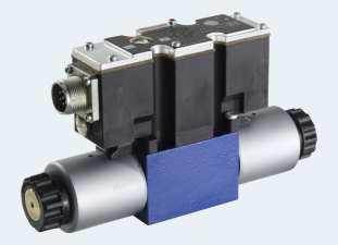
 Electric Drives and Controls Hydraulics Linear Motion and Assembly Technologies Pneumatics Service 4/2 and 4/3-Way Proportional Directional Control Valve Direct Operated Model 4 WRA(E)B Size 6 Series 1X
CONTINENTAL HYDRAULICS VED03MX
 CONTINENTAL HYDRAULICS VED03MX HIGH PERFORMANCE, SERVO-PROPORTIONAL DIRECTIONAL CONTROL VALVE 5505 WEST 123RD STREET SAVAGE, MN 55378-1299 / PH: 952.895.6400 / WWW.CONTINENTALHYDRAULICS.COM VED03MX HIGH
Troubleshooting Bosch Proportional Valves
 Troubleshooting Bosch Proportional Valves An Informative Webinar Developed by GPM Hydraulic Consulting, Inc. Instructed By Copyright, 2009 GPM Hydraulic Consulting, Inc. TABLE OF CONTENTS Bosch Valves
MCV102A. Pressure Control Servovalve DESCRIPTION FEATURES ORDERING INFORMATION. BLN Issued: October 1998
 MCV102A Pressure Control Servovalve Issued: October 1998 DESCRIPTION The MCV102A Pressure Control Servovalve (PCS) is a twostage, fourway, closed loop electrohydraulic servovalve that provides an output
SM4-30 Servovalves Flows to 113 l/min (30 USgpm) Pressures to 140 bar (2000 psi)
 Pressures to 140 bar (2000 psi)") Vickers Servo Valves SM4-30 Servovalves Flows to 113 l/min (30 USgpm) Pressures to 140 bar (2000 psi) Released 1/94 653 Introduction Vickers SM4-30 servovalves can provide system closed loop control with
Vickers Servo Valves SM4-30 Servovalves Flows to 113 l/min (30 USgpm) Pressures to 140 bar (2000 psi) Released 1/94 653 Introduction Vickers SM4-30 servovalves can provide system closed loop control with
Lecture 6. This week: Lab 13: Hydraulic Power Steering [ Lab 14: Integrated Lab (Hydraulic test bench) ]
![Lecture 6. This week: Lab 13: Hydraulic Power Steering [ Lab 14: Integrated Lab (Hydraulic test bench) ]](/thumbs/84/91055223.jpg "Lecture 6. This week: Lab 13: Hydraulic Power Steering [ Lab 14: Integrated Lab (Hydraulic test bench) ]") 133 Lecture 6 This week: Lab 13: Hydraulic Power Steering [ Lab 14: Integrated Lab (Hydraulic test bench) ] 4-way directional control valve; proportional valve; servo-valve Modeling / Analysis of a servo-valve
133 Lecture 6 This week: Lab 13: Hydraulic Power Steering [ Lab 14: Integrated Lab (Hydraulic test bench) ] 4-way directional control valve; proportional valve; servo-valve Modeling / Analysis of a servo-valve
STAR. series. 2-Stage Servovalve Flight Simulation Motion Control. Features
 STAR series 99 2-Stage Servovalve Flight Simulation Motion Control Features Maximum operating pressure 14 bar ISO 1372-6-5--92 mounting pattern Internal pilot supply (4 port) Low hysteresis & zero point
D633/D634 SERVOVALVES FOR ELECTROHYDRAULIC POSITION, VELOCITY, PRESSURE OR FORCE CONTROL SYSTEMS WITH HIGH DYNAMIC RESPONSE REQUIREMENTS
 SERVOVALVES DIRECT DRIVE SERVOVALVES D633/D634 SERVOVALVES FOR ELECTROHYDRAULIC POSITION, VELOCITY, PRESSURE OR FORCE CONTROL SYSTEMS WITH HIGH DYNAMIC RESPONSE REQUIREMENTS Rev. 2, 04/2009 ISO 4401 SIZES
4/3-way servo solenoid directional control valves, pilot operated, with electrical position feedback (Lvdt DC/DC ±10V)
") 1/16 4/3-way servo solenoid directional control valves, pilot operated, with electrical position feedback (Lvdt DC/DC ±1V) RE 2986/1.9 Replaces: 1.5 Type 4WRL 1...35, symbols V/V1 Sizes (N) 1, 16, 25,
1/16 4/3-way servo solenoid directional control valves, pilot operated, with electrical position feedback (Lvdt DC/DC ±1V) RE 2986/1.9 Replaces: 1.5 Type 4WRL 1...35, symbols V/V1 Sizes (N) 1, 16, 25,
Fincor DC Drives. Flexible & Powerful TYPICAL APPLICATIONS. Conveyor Rugged. Extruder Reliable. Conveyor Simple. Mixer Flexible
 DC Drives Flexible & Powerful single-phase DC drives provide a complete family solution from the compact Series 2120 chassis drive to the powerful Series 2230 and it s feature rich application specific
Vickers. Proportional Valves. EPV10 Series. Proportional Flow Controls. Released 6/95
 Vickers Proportional Valves EPV1 Series Proportional Flow Controls Released 6/95 715 Table of Contents Features and Benefits..............................................................................
Servo directional valve of 4-way design Type 4WS.2E
 RE 9 83/7.3 Replaces:. Servo directional valve of 4-way design Type 4WS.E Nominal size Series X Maximum operating pressures 31 bar Maximum flow 1 L/min H//D 89/97 Overview of contents Contents age Features
Pilot-Operated Proportional DC Valve Series D*1FH
 Characteristics The pilot-operated proportional DC valves series of the D*1FH series are high-performance valves with electronic spool position feedback. These valves are available in sizes NG10 to NG2
The DPQ Series 2X Digital Injection Process Controller
 Electric Drives and Controls Linear Motion and Assembly Technologies Pneumatics Service The DPQ Series 2X Digital Injection Process Controller The Drive & Control Company 1 The Injection Process Perfect
Servo solenoid valves with on-board electronics (OBE)
") Electric Drives and Controls Hydraulics Linear Motion and Assembly Technologies Pneumatics Service Servo solenoid valves with on-board electronics (OBE) RA 29045/01.05 1/12 Model 5WRPE 10 Size 10 Unit
Electric Drives and Controls Hydraulics Linear Motion and Assembly Technologies Pneumatics Service Servo solenoid valves with on-board electronics (OBE) RA 29045/01.05 1/12 Model 5WRPE 10 Size 10 Unit
VED05MJ - PROPORTIONAL DIRECTIONAL CONTROL VALVES WITH OBE & POSITION FEEDBACK
 CONTINENTAL HYDRAULICS VED05MJ PROPORTIONAL DIRECTIONAL CONTROL VALVES WITH OBE & POSITION FEEDBACK VED05MJ - PROPORTIONAL DIRECTIONAL CONTROL VALVES WITH OBE & POSITION FEEDBACK 5505 WEST 123RD STREET
G761 Series Servovalves ISO Size 04
 G761 Series Servovalves ISO 137 Size 4 TWO STAGE SERVOVALVES G761 SERIES SERVOVALVES The G761 Series flow control servovalves are throttle valves for 3-, and preferably 4-way applications.they are a high
SM4-10/12/15 Servovalves Flows to 57 l/min (15 USgpm) Pressures to 210 bar (3000 psi)
 Pressures to 210 bar (3000 psi)") Vickers Servo Valves SM4-10/12/15 Servovalves Flows to 57 l/min (15 USgpm) Pressures to 210 bar (3000 psi) Released 12/93 651 Introduction Vickers SM4-10/12/15 servovalves can provide system closed loop
Vickers Servo Valves SM4-10/12/15 Servovalves Flows to 57 l/min (15 USgpm) Pressures to 210 bar (3000 psi) Released 12/93 651 Introduction Vickers SM4-10/12/15 servovalves can provide system closed loop
PROPORTIONAL VALVES SERVO VALVES. Maximum operating pressure MPa {kgf/cm 2 } Model [Model No.]
![PROPORTIONAL VALVES SERVO VALVES. Maximum operating pressure MPa {kgf/cm 2 } Model [Model No.]](/thumbs/82/85298236.jpg "PROPORTIONAL VALVES SERVO VALVES. Maximum operating pressure MPa {kgf/cm 2 } Model [Model No.]") J PROPORTIONAL VALVES SERVO VALVES J Model [Model No.] Solenoid pilot operated proportional relief valve [JRP] Solenoid operated proportional relief valve [JRPL] Type C2 solenoid operated proportional
J PROPORTIONAL VALVES SERVO VALVES J Model [Model No.] Solenoid pilot operated proportional relief valve [JRP] Solenoid operated proportional relief valve [JRPL] Type C2 solenoid operated proportional
3/3-Way-Proportional Valve
 3/3-Way-Proportional Valve Content Page General Description 1 Design 2 Function 2 Technical Data 3 Options 4 Dimensions 5 Accessories 6 Flow Curves 7 General Description This proportional valve in combination
Proportional flow control valve 2-way version, Type 2FRE 10, Huade América 1
 Proportional flow control valve 2-way version, Type 2FRE 10, 16... Huade América 1 EIJING HUADE HYDRAULIC INDUSTRIAL GROUP CO.,LTD. Proportional flow control valve 2-way version Type 2FRE 10 16... Size
series 2-Stage Servovalve Rated flows up to 20 l/m Features
 series 46 2-Stage Servovalve Rated flows up to 2 l/m Features Standard & high response versions Maximum operating pressure 15 bar ISO 441---4 mounting pattern Internal pilot supply (4 port) Suitable for
Control Valves Positioner
 Control Valves Positioner HiFlo Valve Positioner Easy calibration Corrosion-resistant cover and base Withstands 150 psi at all parts Two -sided cam for easy field reversibility Optional / NPT for piped
Control Valves Positioner
 Control Valves Positioner HiFlo HiFlo Valve Positioner Corrosion-resistant cover and base Easy calibration Withstands 150 psi at all parts Two -sided cam for easy field reversibility Optional / NPT for
LS System. solutions for the. Smart Designer. precision high-speed proportional pneumatic systems
 LS System solutions for the Smart Designer precision high-speed proportional pneumatic systems LS System Overview Create breakthrough applications and enhance existing applications Overcome speed and control
Vickers. Servo Valves. SM4-40 Servovalves. Flows to 151 l/min (40 USgpm) Pressures to 350 bar (5000 psi) Released 1/94
 Pressures to 350 bar (5000 psi) Released 1/94") Vickers Servo Valves SM4-40 Servovalves Flows to 151 l/min (40 USgpm) Pressures to 350 bar (5000 psi) Released 1/94 654 Introduction Vickers SM4-40 servovalves can provide system closed loop control with
Vickers Servo Valves SM4-40 Servovalves Flows to 151 l/min (40 USgpm) Pressures to 350 bar (5000 psi) Released 1/94 654 Introduction Vickers SM4-40 servovalves can provide system closed loop control with
631 Series Servovalves ISO 4401 Size 05
 631 Series Servovalves ISO 4401 Size 05 TWO STAGE SERVOVALVES 631 SERIES SERVOVALVES The 631 Series flow control servovalves are throttle valves for 3- and preferably 4-way applications.they are a medium
Industrial Hydraulics FAQs
 Industrial Hydraulics FAQs FAQ Title: H in 4WRPEH model code Category: Proportional and Servo Valves Sub-Category: Directional Control Valves Bosch Rexroth Corporation Hydraulics 2315 City Line Road Bethlehem,
Lecture 7. Lab 14: Integrative lab (part 2) Lab 15: Intro. Electro-hydraulic Control Setups (2 sessions)
 Lab 15: Intro. Electro-hydraulic Control Setups (2 sessions)") Coming week s lab: Lecture 7 Lab 14: Integrative lab (part 2) Lab 15: Intro. Electro-hydraulic Control Setups (2 sessions) 4 th floor Shepherd (room # TBD) Guest lecturer next week (10/30/15): Dr. Denis
Coming week s lab: Lecture 7 Lab 14: Integrative lab (part 2) Lab 15: Intro. Electro-hydraulic Control Setups (2 sessions) 4 th floor Shepherd (room # TBD) Guest lecturer next week (10/30/15): Dr. Denis
SHOCK ABSORBER/DAMPER TESTING MACHINE
 SHOCK ABSORBER/DAMPER TESTING MACHINE Dampening force of a shock absorber is directly proportional to velocity and this parameter needs to be precisely controlled. A small variation of 1mm in a stroke
Pilot Operated Proportional DC Valve Series D*1FW / D*1FT
 Characteristics The D*1FW / D*1FT pilot-operated proportional DC valves are available in NG10 (CETOP5), NG16 (CETOP7) and NG25 (CETOP8). These valves (D*1FW) are controlled electrically with the external
Proportional directional valves, pilot operated, with electrical position feedback and integrated electronics (OBE)
") Proportional directional valves, pilot operated, with electrical position feedback and integrated electronics (OE) RE 29075/08.13 Replaces: 08.04 1/22 Type 4WRKE Size 10 to 35 Component series 3X Maximum
Proportional directional valves, pilot operated, with electrical position feedback and integrated electronics (OE) RE 29075/08.13 Replaces: 08.04 1/22 Type 4WRKE Size 10 to 35 Component series 3X Maximum
FEASIBILITY STYDY OF CHAIN DRIVE IN WATER HYDRAULIC ROTARY JOINT
 FEASIBILITY STYDY OF CHAIN DRIVE IN WATER HYDRAULIC ROTARY JOINT Antti MAKELA, Jouni MATTILA, Mikko SIUKO, Matti VILENIUS Institute of Hydraulics and Automation, Tampere University of Technology P.O.Box
Proportional pressure reducing valve, 3-way variant, pilot operated
 roportional pressure reducing valve, 3-way variant, pilot operated RE 29286/1.1 Replaces: 2.8 1/14 ypes 3DRE(M) and 3DRE(M)E Sizes 1 and 16 Component series 7X Maximum pressure setting 315 bar (size 1)
PRM7-04. Functional Description HA /2012. Proportional Directional Control Valves. Replaces HA /2009
 Proportional Directional Control Valves PRM7-6/ Size D () bar (6 PSI) L/min (. GPM ) Replaces /9 Digital control Compact design Operated by proportional solenoids High sensitivity and slight hysteresis
Proportional Valves. Proportional solenoid valves for pressure and flow control
 Proportional Valves Proportional solenoid valves for pressure and flow control EATON Vickers Screw-In Cartridge Valves V-VLOV-MC-E4 September, 7 - Electro- Proportional Valves Section Contents Typical
STAR. series. 2-Stage Servovalve Rated flows up to 20 l/m. Features
 STAR series 454 2-Stage Servovalve Rated flows up to 2 l/m Features Standard & high response versions Maximum operating pressure 15 bar ISO 172-2-2-2 mounting pattern Internal pilot supply (4 port) Suitable
What does pressure refer to in relation to hydrostatics and what is it dependent on?
 Question 1 [3 Marks] What does pressure refer to in relation to hydrostatics and what is it dependent on? Question 2 [14 Marks] Make a circuit diagram of a regular hydraulic plant that is used to control
Servo solenoid valves with electrical position feedback (Lvdt AC/AC)
") Servo solenoid valves with electrical position feedback (Lvdt AC/AC) Type 4WRPH6 Size 6 Unit series 1X Maximum working pressure 250 bar Nominal flow rate 4...40 l/min ( p 70 bar) List of contents Contents
Servo solenoid valves with electrical position feedback (Lvdt AC/AC) Type 4WRPH6 Size 6 Unit series 1X Maximum working pressure 250 bar Nominal flow rate 4...40 l/min ( p 70 bar) List of contents Contents
test with confidence HV Series TM Test Systems Hydraulic Vibration
 test with confidence HV Series TM Test Systems Hydraulic Vibration Experience. Technology. Value. The Difference. HV Series TM. The Difference. Our philosophy is simple. Provide a system designed for optimum
Proportional Valve.
 Proportional Valve Electro-Hydraulic Proportional Pilot Relief Valve Electro-Hydraulic Proportional Flow & Directional Control Valve Electro-Hydraulic Proportional Relief & Flow Control Valve Electronic
Proportional pressure reducing valve, pilot operated
 Proportional pressure reducing valve, pilot operated RE 29175/7.5 Replaces: 11.2 1/1 Types DRE and ZDRE Size 6 Component series 1X Maximum operating pressure 21 bar Maximum flow l/min H446 Table of contents
series 2-Stage Servovalve Rated flows up to 55 l/m Features
 series 456 2-Stage Servovalve Rated flows up to 55 l/m Features Standard & high response versions Maximum operating pressure 15 bar Special mounting pattern Internal pilot supply (4 port) Suitable for
PRM7-06. Functional Description HA /2006. Proportional Directional Control Valves. Replaces HA /2002
 Proportional Directional Control Valves PRM7-6 HA 59 /6 Size D (6)...6 PSI ( bar)...6 GPM ( L/min) Replaces HA 57 / Digital control Compact design Operated by proportional solenoids High sensitivity and
PRM7-06. Functional Description HA /2014. Proportional Directional Control Valves. Replaces HA /2013
 Proportional Directional Control Valves PRM7-6 / Size 6 (D ) bar (76 PSI) L/min (.6 GPM) Replaces HA 7 / Digital control Compact design Operated by proportional solenoids High sensitivity and slight hysteresis
TECHNICAL DOCUMENT EPC HORSEPOWER LIMITING
 ELECTRONIC 1 A pump is a volume output device only. It delivers oil flow directly related in polarity and amplitude to the command voltage input to the pump amplifier (). Pressure at the pump output is
4/2 servo solenoid valves with on-board electronics (OBE), positive overlap and position feedback
, positive overlap and position feedback") Electric Drives and Controls Hydraulics Linear Motion and Assembly Technologies Pneumatics Service 4/2 servo solenoid valves with on-board electronics (OBE), positive overlap and position feedback RA 29024/01.05
Electric Drives and Controls Hydraulics Linear Motion and Assembly Technologies Pneumatics Service 4/2 servo solenoid valves with on-board electronics (OBE), positive overlap and position feedback RA 29024/01.05
Proportional flow control valve 2-way versiontype 2FRE 6...RC
 Proportional flow control valve 2-way versiontype 2FRE 6...RC Huade América 1 BEIJING HUADE HYDRAULIC INDUSTRIAL GROUP CO.,LTD. Proportional flow control valve 2-way version Type 2FRE 6...RC Size 6 up
Solenoid Pilot Operated Proportional Directional Control Valve
 Solenoid Pilot Operated Proportional Directional Control Valve Features hese solenoid pilot operated proportional directional control valves use a nozzle flapper valve as pilot valve and perform spool
OVERVIEW SERVO VALVE RANGE
 OVERVIEW SERVO VALVE RANGE FLEXIBLE DESIGN, HIGH PRODUCTIVITY WHAT MOVES YOUR WORLD VALVE TYPES EXPLAINED MECHANICAL FEEDBACK (MFB) ELECTRICAL FEEDBACK (EFB) DIRECT DRIVE VALVE (DDV) DIGITAL (DCV) AND
72 Series Servovalves
 72 Series Servovalves TWO STAGE SERVOVALVES 72 SERIES SERVOVALVES The 72 Series flow control servovalves are throttle valves for 3 and preferably 4-way applications.they are a high performance, two-stage
An Introduction to Fatigue Testing Equipment, Test Setup & Data Collection
 An Introduction to Fatigue Testing Equipment, Test Setup & Data Collection Lisa Goodwin Servohydraulic Sales Specialist & Market Manager - Instron The difference is measurable 1 Themes.. Certainty of Measurement
HS CYCLIC CUM STATIC TRIAXIAL TEST SYSTEM
 HS28.610 CYCLIC CUM STATIC TRIAXIAL TEST SYSTEM Meets the essential requirements of ASTM-5311/3999 Introduction The system is a highly advanced combination of hydraulic and pneumatic technology where σ1
 Flow Line Controls Positioner Specifications Series 55 3-15 psi Pneumatic Series 56 4-20 ma Electro-Pneumatic Series 55 Series 56 Flow Line Controls, Inc. P.O. Box 677 Schriever, LA 70395 Phone: 985-414-6003
Servo solenoid valves with electrical position feedback (Lvdt DC/DC) (ruggedized design)
 (ruggedized design)") Servo solenoid valves with electrical position feedback (Lvdt DC/DC) (ruggedized design) RE 29026/01.05 1/14 Replaces: 11.02 Type 4WRPH Size 6, 10 Unit series 2X Maximum working pressure P, A, B 315 bar,
Servo solenoid valves with electrical position feedback (Lvdt DC/DC) (ruggedized design) RE 29026/01.05 1/14 Replaces: 11.02 Type 4WRPH Size 6, 10 Unit series 2X Maximum working pressure P, A, B 315 bar,
Proportional directional valves type DHZO-T* and DKZOR-T* direct operated, with position transducer, ISO 4401 size 06 and 10
 www.atos.com Table F65-/E Proportional directional valves type DHZO-T* and DKZOR-T* direct operated, with position transducer, ISO 440 size 06 and 0 Valve body Spool Proportional solenoid Position transducer