Catalogue. We provide superior performing compressed air & gas systems with engineered longevity to reduce operating costs and improve productivity.
|
|
|
- Eric Lloyd
- 5 years ago
- Views:
Transcription


1 We provide superior performing compressed air & gas systems with engineered longevity to reduce operating costs and improve productivity. ENGINEERED FOR SUPERIOR PERFORMANCE Compressed Air & Gas Systems Catalogue U.S. Headquarters - AIRpipe USA Tel:2.362.PIPE (7473) 68 S. Kyrene Rd, Suite #101, Tempe, AZ customerservice@airpipeusa.com Web: Publication Aippipe #4//USA Airpipe reserves the rights to modify this documents without prior notice.


 and lugged ring (-0mm) allows for zero risk of")


2 Engineered for AIRpipe specializes in solutions for compressed air and fluids distribution. Throughout the last 10 years we have continued to invest in R&D; taking into account market feedback and real-world conditions. Our products are engineered to be the most Competitive Advantage Superior reliability ongevity Cost savings Quick & easy install superior available - Advancing the compressed air & gas piping industry. AIRpipe maintains a >300,000 sq ft campus for manufacturing, R&D, and logistics. We a r e committed to being your total system solutions provider. Superior Reliability & ongevity Highly-durable materials resistant to corrosion, vibration, thermal variation, and outdoor weather conditions. Metal clamshell connectors for all diameters are stronger and more durable versus polymer fittings. Unique grab ring design (-mm) and lugged ring (-0mm) allows for zero risk of disconnection. Patented active concentric seals provide leak-free performance, even in high vibration applications. Seal lifespan is double that of industry competitors. Energy & Cost Savings The smooth interior design and highflow connectors ensures a constant supply of clean air at a reduced pressure drop, resulting in significant energy savings. Quick & Easy Modular Installation Complete range of pipe, fittings and accessories works easily for new projects renovations & extensions. Requires no special tooling, welding, gluing, brazing, soldering, or thread Guaranteed leak-free performance and cutting. superior longevity versus traditional pipe systems. Reusable, lightweight, and modular design allows for easy modifications. Quick drops can be added at any time to create new points of use. 01/02

 Vacuum Vacuum: 3.")
 Compressor oil carry over (mineral/synthetic) Recyclability % recyclable. Pipe Screw Seal Metal clamshell union connector, quick install & reassembly.")
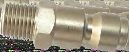
3 Connection Technology Technical Specifications AIRpipe innovative modular technology enables rapid and easy assembly via quick connection of fittings to the aluminum pipe. This technology takes into account the specific requirement of each diameter to provide the user with a secure connection. Suitable fluids Compressed air (dry, wet, lubricated) Vacuum Inert gases (including Argon, Helium, Nitrogen, CO2 mixes) Max. Working pressure Max. working pressure: 232 psi. *(Max. working pressure for DN0 is 8 psi.) Vacuum Vacuum: 3.8 inches of mercury (absolute pressure ) Grab Ring Metal Clamshell Grab Ring Clamping Style Connection DN - DNmm Corrosion Aggressive environments Mechanical shocks Resistance to Thermal variations Ultraviolet (U.V.) Compressor oil carry over (mineral/synthetic) Recyclability % recyclable. Pipe Screw Seal Metal clamshell union connector, quick install & reassembly. Grab ring with surface contact, no shrinking on inner diameter. Surface contact, active conentric sealing, leak free. Superior reliability & longevity. Flow N m3/h ength Metal Clamshell ug ugged Ring Clamping Style Connection DN - DN0mm Metal clamsheel union connector, quick install & reassembly. Convex ring, no shrinking on inner diameter. Seal Surface contact, active conentric sealing, leak free. Superior reliability & longevity. Screw Closed loop system at 116 psi with 5% allowable pressure drop. Pipe Example Main system length (ring main): 0m Required flow rate: 312 SCFM Working pressure: 116 psi Result: The most suitable AIRpipe diamter is: Dnmm 03/04


4 Warranty and Certifiations 10 CONTENT 10 Year imited Warranty: AIRpipe USA warranties its products to be free of defects in material and workmanship for a period of ten years from the date of product purchase. No other warranties, express or implied are made by AIRpipe USA. This limitation explicitly excludes any implied warranty of merchantability or fitness for a particular purpose. The sole remedy for breach of this warranty of material and workmanship or for negligence in manufacture or design is limited to replacement or repair, at the sole digression of AIRpipe USA. In no event shall AIRpipe USA, it s parent, and sister companies be liable for indirect, special, incidental or consequential damages of any kind. No allowance will be made for repairs made by the purchaser. AIRpipe USA does not warrant the design, assembly or installation of the system, but only the components listed within AIRpipe USA s price list. AIRpipe USA is not responsible for improper assembly, installation, or for any modifications of the product. The warranty is void upon (a) failure to follow assembly or installation guidelines; (b) alteration, misuse or abuse of, or damage to the products; (c) operation beyond the design range, excessive pressure, stress, or mishandling in any way; (d) use other than for the intended purpose or in a manner other than specified by AIRpipe USA. Engineering standards: ASME B31.1 & B31.3 U94HB U94V-2 TUV CE & EN PED 14/68/EU TS ASTM B241, EN7-8, GB/T , JIS H Certifications and Compliances: ISO 9001 version 00 ISO 101 version 04 ISO version 10 ASME, U, TUV, CRN, CE, EN and TS 14/68/EU Rigid Pipe 07 Connectors 08 Quick Drop Connectors 14 Wall Brackets & Valved Connectors 15 Flanged Connectors 17 Flexible Hose 19 Fixtures & Accessories Tools 23 Installing AIRpipe 05/06
 Optimum")


 Working temperature: -4")


 ID(mm) (M).")


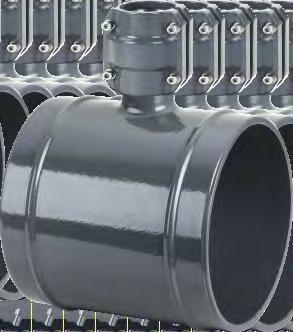
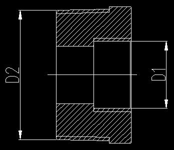
5 Rigid Pipe Connectors Clean air certified (ISO ) Optimum flow performance ightweight High quality powder coated exterior Extruded marine grade aluminum Suitable for Compressed air, oil-free or lubricated, vacuum, and inert gases (Nitrogen, Argon, Helium) Max.working pressure: 232 psi Max.working pressure for DN 0 is 8 psi Vacuum: 3.8 inches of mercury (absolute pressure) Working temperature: -4 up to +176 Quick connection Superior reliability & longevity Designed for extreme environments Pipe to Pipe Connector Modular and reusable % recyclable and non-flammable materials (U94-HB Standard) Blue / Grey / Green A B OD( mm) ID(mm) (M) Outer Dia.mm Inner Dian.mm Pipe to Pipe Connector A A A A B Equal 90º Elbow *Other colors, please consult us A /08


6 Equal 90º Elbow Reducing Tee Z x x x A x *Supplied with (2) union connectors. Equal 45º Elbow Reducing Tee 1 Z x x x x Equal 45º Elbow 87 x 6 *Supplied with (2) union connectors A *Supplied with (2) union connectors Reducing Tee x x x 1x Z Equal Tee A7 1x 1x 0x A7 0x A7 0x A907 0x *Supplied with (2) union connectors. Equal Tee Equal Wye A A *Supplied with (3) union connectors. *Supplied with (3) union connectors. 09/10


 union connectors.")


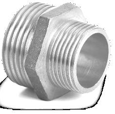
7 Reducing Wye 1 2 End Cap 8712 x x x A812 0x A912 0x A *Supplied with (3) union connectors. *Supplied with a union connector. Reducing Pipe to Pipe Connector Male Threaded Elbow 2121 x DN 1 2 NPT x x x Reducing Pipe to Pipe Connector *Note: Suitable for connecting to air compressors, dryers, and filters x x Female Threaded Elbow 1 71 x *Supplied with a union connector. DN 1 2 NPT Reducing Pipe to Pipe Connector 7621 x x 1 *Note: Suitable for connecting to air compressors, dryers, and filters x x x 172 A921 0x1 1 Female Threaded Adapter End Cap *Supplied with (2) union connectors. NPT /12


8 Female Threaded Adapter Quick Drop Connectors Male Threaded Adapter *Supplied with a union connector NPT 2-3" NPT All-aluminum body Alignment stub design for quick installation Quick Drop Straight Quick Drop A210 x x x x x x x x x x x x 1x 1x 0x Optimum flow Captivated seal Drill Drill x A410 A510 1x 1x 0x 0x ¼" Female Threaded Quick Drop DN x NPT 1 2 Drill x x x x x Male Threaded Adapter Female Threaded Quick Drop NPT DNxNPT x x x Drill x " 11 x *Supplied with a union connector x /14


9 Wall Brackets & Valved Connectors Angled Two-port Female Wall Bracket Connector Quick connection Available for BSP/NPT thread, flange and plug-in connection type High-flow design ensure optimal performance Nickel-plated brass Two port, 75 Two port, * Material of Valve Body : Brass * Includes Mounting Plate and Hardware. ocking Handle Quick Connect Valve D D2 242 * Material of Valve Body: Brass. * ocking Handle. One & Two Port Angled Wall Brackets Connector One port One-port Female Wall Bracket D * Material of Body : Aluminium * Incoudes a 1/4'' venting valve 45 One port 45 Two ports 45 Two ports ½ D * Material of Valve Body : Brass * Includes Mounting Plate and Hardware. * ocking Handle Threaded Ball Valve D2 Thread Two-port Female Wall Bracket D Female Female Male Male Male* Female Male* Female Female Female Female * Material of Valve Body : Brass * Includes Mounting Plate and Hardware. * ocking Handle * Material of Valve Body : Brass * ocking Handle D2 Butterfly Valve Pre-Assembled Material of valve Male Threaded Quick Connect Valve Cast Iron Cast Iron D A Cast Iron Cast Iron Cast Iron Stainless Steel D Stainless Steel 53 * Material of Valve Body : Brass * ocking Handle A Stainless Steel Stainless Steel Stainless Steel 15/16
 1 0 *Includes bolts and gasket.")


 for DN/DN/DN/Dn *Includes 1")

10 Flange Connectors ANSI Flange ANSI Female Threaded Flange ANSI Reducing Flange A1 (OD) 1 0 *Includes bolts and gasket. *Supplied with union connector Flange size Bolt size M M D2 D Female thread ½ 2-½ 2-½ 3 Bolt size M14 M14 M M M M D D3 14 H * Above flange material: stainless steel. Female thread Bolt size D2 D3 H *Includes bolts and gasket. *Supplied with union connector Flange size Bolt size M D2 D *Includes 1 gasket and 4 bolts(7cm) for DN/DN/DN/Dn *Includes 1 gasket and 8 bolts(7cm) for DN/DN/DN ½ 2-½ 2-½ 3 * Above flange material: Carbon steel. M14 M14 M M M M /


 81 101.8 66.93 74. D 10.1 19.")

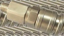
11 Flexible Hose Fixtures & Accessories Suitable for Compressor & equipment outlets to absorb vibration Bypass obstacles Allows for expansion and contraction of loops Resistant to mineral and synthetic lubricated oils. Suitable for various pipe systems Used for a variety of installation methods, eg: wall, beam, roof, channel, rod, cable, etc, vertically or horizontally Non-flammable Designed to work best with AIRpipe system Flexible Hoses Fixture Clip D I H a b DN-DN X1 10 3/8'' 3/8'' 3/8'' /8'' DN-DN X1 67 3/8'' 3/8'' 3/8'' * 3/8"-16 threaded rod port. Clip Spacer DN-DN X0 DN-DN0 Compatible sizes a b c X ~ ~ *Spacer clip 0027 is used to create a level plane for D Remark Ss304 material, 30 ¾''or 1'' diameters transitioning to 1 ½'', 2'', or 2 ½''. *Spacer clip 0127 is used to create a level plane fo r 1 ½'', 2'', or 2 ½'' diameters transitioning to 3'' or 4'' Rubber material, 30 Fixture Clip (Steel) D SS304 material, 30 Ss304 material, Straight connection A A *3/8"-16 threaded rod port 19/


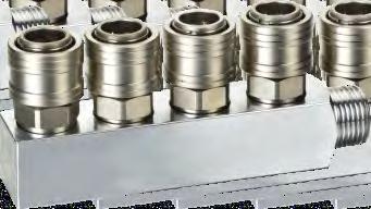

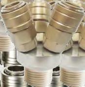

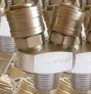


12 Threaded Adapter 54 Female Male D2 Material 1-1- Water Drain Valve " 3" 3" 0973 *Oneballvalveisneeded. Inlet size Female thread " 83 ¼" Universal Quick Couplers 14 Applicable ¼ " Universal Quick Coupler (ISO 61B / Automotive), Male NPT D2 Material 3/8" Universal Quick Coupler (ISO 61B / Automotive), Male NPT ¼" " Male NPT Automotive Nipple ¼ 3/8" Male NPT Automotive Nipple " Male NPT Industrial (ISO B) Nipple ¼ 3/8" Male NPT Industrial (ISO B) Nipple Threaded Adapter Electronic Drain Valve D2 Material Note:UsedfortheconnectionbetweentwoFilters. Inlet size 0873 *Oneballvalveisneeded. Display Kit Manifolds D Connection Port 0283 Male Two-port manifold H I Male Male Three-port manifold Four-port manifold *Inletsandoutletsare½'' *Universalcouplersaresoldseparately. 21/


 Hole Deburrer")


")


")


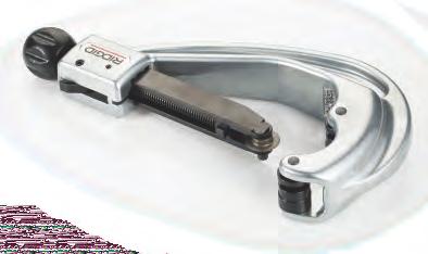


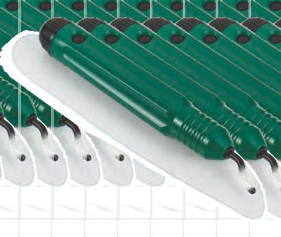


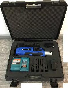


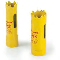
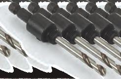
13 Tools Hole Deburrer Tool Bag - Part Number 0045 Component Description Applicable diameter 0141 mm to mm ( to ) Pipe Deburrer DN-DN mm to 0 mm ( to 8") Hole Deburrer Drill Arbor & Pilot Bits for and 51 mm Hole Saw Bits 51 mm Hole Saw Bit Drill Arbor & Pilot Bit 0443 mm Hole Saw Bit 0343 mm Hole Saw Bit Drill Arbor & Pilot Bit for 16,, and mm Hole Saw Bits. mm Hole Saw Bit 16 mm Hole Saw Bit mm to mm ( to 2 ) Pipe Cutter Applicable Drill Applicable diameter 16- DN~DN -51 DN1~DN0 PM 0044 Permanent Marker Pipe Insertion Depth Gauge Hole Saw Bit 4 mm 5 mm 6 mm 4 mm Hex Bit ( in length) for Drill 5 mm Hex Bit ( in length) for Drill 6 mm Hex Bit ( in length) for Drill D Applicable diameter 16 DN DN *ContainsalltoolingforDN-,alongwithhexandholesawbits foralldiametersandquickdropfittings *For DN and DN pipe installation, 01 and 04 are needed. 8 mm 8 mm Hex Bit ( in length) for Drill 0046 Tool Bag *Itemsareavailableforindividualpurchase DN~DN0 DN DN1~DN0 *For DN1 and DN0 pipe installation, 0344 and 04 are needed. Unistrut Nut Electric Pipe Cutter Pipe Cutter pipe deburrer Applicable 07 3/8''-16 threaded rod port Portable ugging Machine 0344 Applicable diameter DN~DN H Applicable diameter DN-DN DN-DN DN-DN H Applicable diameter Applicable diameter Remark 04 DN~DN0 Contains every jaw set 23/24
.airpipeshouldbeinstalleddownstreamofthecompressedairreceiver,orafterthedryer.")

isrequired.")
14 Installing AIRpipe Measuring Pipe Insertion Depth General General PriortotheinstallationofaAIRpipecompressedairdistributionsystem,theinstallershouldensurethattheinstallationarea complieswithanyregulationsapplicabletoareasexposedtoexplosivehazards(inparticulartheeffectofstaticelectricityina siloarea).airpipeshouldbeinstalleddownstreamofthecompressedairreceiver,orafterthedryer.flexibleairpipehosecan beinstalledatthestartofthesysteminordertoeliminateanysourcesofvibrationandtofacilitatemaintenanceoperations. WhenmaintainingormodifyingaAIRpipesystem,therelevantsectionshouldbeventedpriortothecommencementofany work.installersshoulduseonlyairpipecomponentsandaccessories,inparticularairpipepipeclipsandfixtureclamps.the technicalpropertiesoftheairpipecomponents,asdescribedintheairpipecatalog,mustberespected. AIRpipealuminumpipeissuppliedreadyforuse.Noparticularpreparation(cutting,deburring,chamfering,etc.)isrequired. ThankstotherigidityofAIRpipealuminumpipe,temperature-relatedexpansion/contractionisreducedtoaminimum.The AIRpipesystemretainsitsstraightness,andhenceitsperformance,overtime(reductionofpressuredropcausedbysurface friction). AIRpipealuminumpipeiscalibratedandfitsperfectlywithallAIRpipecomponents. Componentassembly Wheninstallingpipediametersto,usetheinsertion depthgauge(partnumber0044)toplaceaninsertiondepth markonthepipe. Drilling indicator An identifying layline is imprinted on each length of pipe that may be used as an alignment guide when installingquickdropconnections. AIRpipecomponentsareprovidedwithassemblyinstructionsfortheircorrectuse-simplyfollowthemethodsand recommendationsstatedinthisdocument. Expansion/contraction Positioning ogo Expansionandcontractionofthesystemshouldbecalculatedpriortoinstallation.Thesystemdesignerandinstallershould calculatetheelongationorretractionofeachairpipelineaccordingtotherecommendationsinthisinstallationguide. Situationstoavoid AIRpipepipeshouldbeprotectedfrommechanicalimpact,particularlyifexposedtocollisionwithfork-lifttrucksorwhensited inanenvironmentwithmovingoverheadloads.similarly,rotationofthepipeandpipesupportsshouldbeavoided.airpipepipe mustnotbewelded.flexibleairpipehosesshouldbeusedinaccordancewiththerecommendationsoftheinstallation guidelines. installationwithinasolidmass(concrete,foam,etc.) thehangingofanyexternalequipmenttoairpipepipe theuseofairpipeforgrounding,orasasupportforelectricalequipment exposuretochemicalsthatareincompatiblewithairpipecomponents(pleasecontactusforfurtherdetails) Cutting the pipe Rotate the corresponding pipe cutter around the pipe while gently tightening the wheel. e Pipe should be cut straight. Best practices to maintain an optimized AIRpipe System Design,installation,andmaintenanceshouldbeperformedinaccordancewithreasonableengineeringknowledge andpracticewithinvolvingpipingsystems Maintainhigh-qualityairlevelswithinyoursystem. Toavoidpressuredropswithinyoursystem,minimizepipediameterreductions Properlysizeyoursystemtoallowforoptimalflowandefficiency. Use part number 00 for pipe diameters ¾'' to 2 ½''. Use part number 01 for pipe diameters 1 ½'' to 4''. Cutting slope of pipe end allowable deviation (e) ~ 1.0 ~ /26


 0243 0243 0243 0643 0643")


 1.")


15 Superior Reliability! Quick and Easy Installation Deburr The Outer and Inner Edges Before Installation Use 0141 for DN-DN to deburr the outer edges and also deburr the inner end. Use a file for DN-DN0 to chamfer the outer edges; make use of a deburring tool to debur the inside of the pipe end. Pilot Bit Hole Saw DN(MM) Quick Drops (PN) Φ16 Φ Φ Φ Φ A A A Insertion Depth S For DN~DN Connector Installation Guide for DN~DN0 DN Insertion depth S (IN) 1.14" 1.14" 1.53" 1.53" Installation Guide for DN~DN 01 Mark the pipe with a marker pen as shown below: "S" denotes the insertion depth of the pipe into the connector. 02 Insert the marked pipe into the connector : Slide the seal over the edge of the pipe so that it sits flush with the lugged edge. Insert the second pipe into the seal until the seal and the lugged edge are flush. Position the clamshell over the seal A portion of the marked lines should remain visible after the pipe is inserted into the connector. 03 Bring the second pipe to the connector and slide up to the marked insertion depth Pull the pipe back towards the outside of the clamshell to Tighten the pre-fitted screws. complete alignment Tighten the pre-fitted screws. Flush the clamshell halves together to complete assembly 06 Tighten the screws in an "X" pattern. To disassemble, perform the same operation in reverse order. 4 2 Tighten the pre-fitted screws. Flush the clamshell halves together to complete assembly For effective assembly, tighten the screws in an "X" pattern. To disassemble, perform the same operation in reverse order /28


16 Hand-held hydraulic lugging machine operation requirements Pipe Clip XX AIRpipe's pipe clips are designed for versatility. They can be secured via all-thread rod through the clips internal 3/8'' 16 nut, or mounted directly with wall anchors. Manually open the jaws of the clamp and insert the aluminum pipe into the clamp as far as possible. Release the jaws.press the trigger and crimp the pipe until a snap sound is heard. m/19ft The bolt size 3/8''-16 is suitable for all fixing clips. This clip allows expansion and contraction of the pipe to occur freely. The fixing clip should be fixed at the min distance of 6 inch (1mm) from the connector in order to allow for the expansion and contraction effect. Spacers for pipe clips Re-open the two jaws to remove the pipe and rotate the pipe slightly.put the jaw side to the mark position. Renew the operation until the required minimum number of lugs for each diameter is finished. Hand-held hydraulic lugging machine operation requirements ugs size for DN~DN DN DN DN DN1 DN0 D3 Min. number of lugs Normal h 0127 Note:Donotoverlapthelugs! 3.0~ ~ ~ ~ ~3.3 Spacer clip 0027 is used to create a level plane for 3/4 '' or 1'' diameters transitioning to 1 1/2'', 2'', or 2 1/2''. Spacer clip 0127 is used to create a level plane for 1 1/2'', 2'', or 2 1/2'' diameters transitioning to 3'' or 4''. 29/30


17 Installing Quick Drop Connectors Mark the pipe where the hole for the quick drop connector will be installed. Identify the drill arbor & hole saw bit required by locating the quick drop part number on the sizing chart. Note: the quick drop part number is located on the connector. Apply steady pressure until the hole saw bit has completely entered the pipe. Remove debris and deburr cut edges With the proper drill arbor & hole saw bit part numbers identified, thread the hole saw bit onto the drill arbor to create a single drill bit. Hold the drill perpendicular to the pipe with the drill bit in the center of the mark placed on the pipe. The quick drop connector easily aligns into the drilled hole. Tighten the bolt to complete assembly 31/32
18 Compensating for the effect of expansion and contraction due to temperature variations Consequences of not properly accounting for thermal variations: eakage and system deformation, that in extreme situations, could result in a connection separation. Pipe system movement could create an obstruction. Quick drop connections could become compromised. 1. In order to compensate for the effects of expansion and contraction due to temperature variations, system lengths should be appropriately evalulated and expansion joints installed where needed. a. Anytime there is a change in temperature between areas. b. If there is a temperature differential of 30 F or more possible in the system. c. For significant lengths of piping. 2. Recommended locations of flexible hoses or expansion loops include but are not limited to. a. The discharge of the compressor. b. The middle of of a long run of pipe. c. Corners of a piping network. d. In a multiple pipeline loop at the beginning of a parallel line internal to the pipeline loop. 3. Best practices include but are not limited to: a. All aluminum piping to be installed in strict accordance with AIRpipe installation instructions and specifications. b. Allowing the corners to expand and contract by placing pipe clips an appropriate distance from each corner. Avoid placing a pipe clip directly in the corner. c. Install piping indicated to be exposed and piping in equipment rooms and service areas at right angles or parallel to building walls. d. Install piping adjacent to equipment and machines to allow service and maintenance. e. Install air and drain piping with 1 percent slope download in direction of flow. f. Install nipples, flanges, unions, transition and special fittings, and valves with pressure ratings same as or higher than system pressure rating, unless otherwise indicated. g. Install branch connections to compressed-air mains from top of main. Provide drain leg and drain trap at end of each main and branch and at low points. h. Install piping to permit valve servicing. i. Install piping free of sags and bends. j. Install unions, adjacent to each valve and at final connection to each piece of equipment and machine. k. Install sleeves and escutcheons for piping penetrations of walls, ceilings, and floors as necessary. l. The fixing clips shall allow axial movement of the pipe to compensate for system expansion and contraction. m.horizontal and vertical AIRpipe piping shall be supported by AIRpipe pipe clips. Hanger rods to be solid with only enough thread for the connection ends. Hangers to be spaced at intervals as described herein, as required to avoid sag, prevent vibration, and allow accurate leveling or grading. 1. Single loop system A) Installing flexible hose in the middle of a pipe run. The distance between pipe clip and the connector should be appropriately sized. Flexible hose B) Installing flexible hose at the corner of a long pipe run 2) Multiloop pipeline Reserve adequate distance from system corners to walls and fixed structures. Consider flexibility for drops from the main header. Note that a hose can be used to compensate for temperature changes at the corners. Compensating for the effects of expansion or contraction. For deformation part, reserve 11.8'' to 19.6'' for stretch. Pipe clips The distance between pipe clip and the corner should be approximately 6' or larger. The distance between pipe clip and the corner should be large than 6.56' x0 328' x1 Compensating for the effects of thermal variation. 656' 33/34
Catalogue. We provide superior performing compressed air & gas systems with engineered longevity to reduce operating costs and improve productivity.
 We provide superior performing compressed air & gas systems with engineered longevity to reduce operating costs and improve productivity. ENGINEERED FOR SUPERIOR PERFORMANCE Compressed Air & Gas Systems
We provide superior performing compressed air & gas systems with engineered longevity to reduce operating costs and improve productivity.
 We provide superior performing compressed air & gas systems with engineered longevity to reduce operating costs and improve productivity. ENGINEERED FOR SUPERIOR PERFORMANCE Compressed Air & Gas Systems
QuickLINE_96.955_Version_28.Octobre.14. QuickLINE COMPRESSED AIR LINE SYSTEM
 QuickLINE_96.955_Version_8.Octobre.4 QuickLINE COMPRESSED AIR LINE SYSTEM COMPRESSED AIR LINE SYSTEM QuickLINE Ready for immediate pressurization QUICK AND EASY TO INSTALL Excellent quality compressed
Transair: Advanced Pipe Systems Pocket Installation Guide [1/2"] [1"] [1 1/2"] [2"] [2 1/2"] [3"] [4"] [6"]
![Transair: Advanced Pipe Systems Pocket Installation Guide [1/2] [1] [1 1/2] [2] [2 1/2] [3] [4] [6]](/thumbs/93/113010388.jpg "Transair: Advanced Pipe Systems Pocket Installation Guide [1/2] [1] [1 1/2] [2] [2 1/2] [3] [4] [6]") Transair: Advanced Pipe Systems Pocket Installation Guide [1/2"] [1"] [1 1/2"] [2"] [2 1/2"] [3"] [4"] [6"] Certifications and guarantees Offering a full range of diameters to fit your design needs. Transair
Transair: Advanced Pipe Systems Pocket Installation Guide [1/2"] [1"] [1 1/2"] [2"] [2 1/2"] [3"] [4"] [6"] Certifications and guarantees Offering a full range of diameters to fit your design needs. Transair
Transair. Specification Submittal
 Specification Submittal About Parker: Transair is part of the Parker Hannifin Corporation (NYSE: PH), which was founded in 1918. With annual sales exceeding $13 billion, Parker Hannifin is the world s
Large Capacity Aluminum Piping System
 Large Capacity Aluminum Piping System High Quality Aluminum Piping Systems Simply stated there is no equal. Elevation from Applied System Technologies (AST), has taken large diameter piping systems to
A. This Section includes piping and related specialties for general-service compressed-air systems operating at 150 psig or less.
 SECTION 221513 - COMPRESSED-AIR PIPING PART 1 - GENERAL 1.1 SUMMARY A. This Section includes piping and related specialties for general-service compressed-air systems operating at 150 psig or less. 1.2
PIPING. Aluminium pipe for inert gases (5,7 m / 18,7 ft) PAGE 2/ AIRNET Ø (MM / INCH) PARTNUMBER LOT SIZE / ¾" 05
 PAGE 2/ AIRNET Ø (MM / INCH) PARTNUMBER LOT SIZE / ¾ 05") PIPING Aluminium pipe for inert gases (5,7 m / 18,7 ft) 2811 1061 05 20 / ¾" 05 2811 2061 05 25 / 1" 05 PAGE 2/99 2014-11-24 Aluminium pipe for air (2,85 m / 9,4 ft) PIPING 2811 1063 10 20 / ¾" 10 2811
PIPING Aluminium pipe for inert gases (5,7 m / 18,7 ft) 2811 1061 05 20 / ¾" 05 2811 2061 05 25 / 1" 05 PAGE 2/99 2014-11-24 Aluminium pipe for air (2,85 m / 9,4 ft) PIPING 2811 1063 10 20 / ¾" 10 2811
SimplAir Piping System. 3/4'' 8'' ( mm) Aluminum Pipe
 Aluminum Pipe") SimplAir Piping System 3/4'' 8'' (20 220 mm) Aluminum Pipe Simplair Specifications Your pipeline to greater cost savings and efficiency The new SimplAir piping system from Ingersoll Rand uses marine-grade
SimplAir Piping System 3/4'' 8'' (20 220 mm) Aluminum Pipe Simplair Specifications Your pipeline to greater cost savings and efficiency The new SimplAir piping system from Ingersoll Rand uses marine-grade
SimplAir Piping System. 3/4'' 8'' ( mm) Aluminum Pipe
 Aluminum Pipe") SimplAir Piping System 3/4'' 8'' (20 220 mm) Aluminum Pipe Your pipeline to greater cost savings and efficiency The new SimplAir piping system from Ingersoll Rand uses marine-grade aluminum pipes to efficiently
SimplAir Piping System 3/4'' 8'' (20 220 mm) Aluminum Pipe Your pipeline to greater cost savings and efficiency The new SimplAir piping system from Ingersoll Rand uses marine-grade aluminum pipes to efficiently
Transair: Advanced Pipe Systems Quick Reference Guide [1/2"] [1"] [1 1/2"] [2"] [2 1/2"] [3"] [4"] [6"]
![Transair: Advanced Pipe Systems Quick Reference Guide [1/2] [1] [1 1/2] [2] [2 1/2] [3] [4] [6]](/thumbs/93/113010396.jpg "Transair: Advanced Pipe Systems Quick Reference Guide [1/2] [1] [1 1/2] [2] [2 1/2] [3] [4] [6]") Transair: Advanced Pipe Systems Quick Reference Guide [1/2"] [1"] [1 1/2"] [2"] [2 1/2"] [3"] [4"] [6"] Innovative Compressed Air Pipe Systems Transair is a fast, flexible and easy to modify aluminum pipe
Transair: Advanced Pipe Systems Quick Reference Guide [1/2"] [1"] [1 1/2"] [2"] [2 1/2"] [3"] [4"] [6"] Innovative Compressed Air Pipe Systems Transair is a fast, flexible and easy to modify aluminum pipe
COMPRESSED AIR SYSTEM 2½" TO 10" Big-Lock Tubing
 COMPRESSED AIR SYSTEM 2½" TO 10" Big-Lock Tubing High Quality Aluminum Piping Systems Simply stated there is no equal. Big-Lock from Gardner Denver has taken large diameter piping systems to a new level.
GRINNELL MODEL CB800 CIRCUIT BALANCING VALVE INSTALLATION & SETTING HANDBOOK
 Technical Services 866-500-4768 +-40-78-8220 GRINNELL MODEL CB800 CIRCUIT BALANCING VALVE INSTALLATION & SETTING HANDBOOK AUGUST 20 IH-4500 Table of Contents Contents General Description.... 3 Dimensional
A Member of the. Integrated Metering Technologies
 I n s t a l l a t i o n M a n u a l A Member of the Integrated Metering Technologies 1.0 General and Safety Do not install, operate or maintain this flow meter without reading, understanding and followingthe
Advanced Air Pipe System Compressed Air, Vacuum, Inert Gas. An Energy Efficient Solution
 Advanced Air Pipe System Compressed Air, Vacuum, Inert Gas An Energy Efficient Solution Transair Innovative Technology Transair s aluminum compressed air pipe system is quick to install and easy to modify.
HALLMARK INDUSTRIES INC
 Performance Part No. HP. CONVERTIBLE JET PUMP USER S MANUAL GPH of Water @ Total Discharge Pressure of 40 psi Max. Pressure Max suction (shallow well) Max Suction (deep well) Max GPM (@0 head) Max Discharge
Series 957, 957N, 957Z, 957RPDA, 957NRPDA, 957ZRPDA
 Series 957, 957N, 957Z, 957RPDA, 957NRPDA, 957ZRPDA Reduced Pressure Zone Assemblies Reduced Pressure Detector Assemblies Sizes: 2 1 2" 10" (65 250mm) Installation Service Repair Kits Maintenance RP/IS-957/957RPDA
TBM Series 3-Way Ball Valve
 www.simtechusa.com TBM Series 3-Way Ball Valve Operating, Installation, & Maintenance Manual Corrosion Resistant Fluid and Air Handling Systems. Dated 06-26-13 TBM Series Ball Valves SIMTECHRECOMMENDSREADINGTHEFOLLOWINGINFORMATIONPRIORTOINSTALLINGANDUSING
Installation and Maintenance Instructions
 Limited One Year Warranty T&S warrants to the original purchaser (other than for purposes of resale) that such product is free from defects in material and workmanship for a period of one (1) year from
Colt Series C400, C500
 Colt Series C400, C500 RP/IS-A-C400/C500 C400 OSY Reduced Pressure Zone Assemblies Reduced Pressure Detector Assemblies Sizes: 2 1 2" 10" (65 250mm) Installation Service Repair Kits Maintenance For other
December 1, 2011
 www.probite.com ProBite List Pricing December 1, 2011 Pricing effective as of December 1, 2011, is subject to change without notice. This pricing revision replaces all previously stated pricing communications.
Manufacturing Facility is ISO9001:2000. Welded Steel Pipe Conform to ASTM A53. Threads Conform to ASME B1.20.1
 STEEL NIPPLES S40 & S80 Steel Nipple Product Specifications Manufacturing Facility is ISO9001:2000 Welded Steel Pipe Conform to ASTM A53 Threads Conform to ASME B1.20.1 800-678-2544 800-678-0857 www.msi-products.com
Grinnell Grooved Fire Protection Products Grooved Fittings
 Technical Services: Tel: (800) 38-932 / Fax: (800) 79-5500 www.tyco-fire.com Grinnell Grooved Fire Protection Products Grooved Fittings General Description LPCB Vd S The grooved fittings provide an economical
INTRODUCTION INSTALLATION
 INTRODUCTION INSTALLATION, OPERATION & MAINTENANCE INSTRUCTIONS This instruction manual includes installation, operation and maintenance information for the figure G73 gear operator. The figure G73 is
GRINNELL Model B302 and Model BN302 Grooved End Butterfly Valves with Gear Operators or Lever-Lock Operators General Description
 Technical Services -00- +-0--0 www.grinnell.com GRINNELL Model B0 and Model BN0 Grooved End Butterfly Valves with Gear Operators or Lever-Lock Operators General Description The GRINNELL Models B0 and BN0
SmartPipe. Product Catalog and Installation Guide. kaeser.com
 SmartPipe Product Catalog and Installation Guide kaeser.com SmartPipe Compressed Air Piping Piping selection directly affects the three key elements of every compressed air system: flow, pressure, and
OPERATION MANUAL NT50 NOMAD TRANS-FLO AIR-OPERATED DOUBLE DIAPHRAGM PUMPS. A JDA Global Company. 7/11 rev. 1
 OPERATION MANUAL NT50 NOMAD TRANS-FLO AIR-OPERATED DOUBLE DIAPHRAGM PUMPS A JDA Global Company 7/11 rev. 1 CAUTION SAFETY POINTS TEMPERATURE LIMITS: Neoprene -17.8 C to 93.3 C 0 F to 200 F Buna-N -12.2
FIGURE 310A & 311A 3-PIECE BALL VALVE
 INTRODUCTION This instruction manual includes installation, operation and maintenance information for the figure 310A, 310ASW, 311A, and 311ASW 3-piece 1000CWP, threaded end (NPT) or socket weld end (SW)
SmartPipe+ Product Catalog ¾ to 2½. kaeser.com
 SmartPipe+ Product Catalog ¾ to 2½ kaeser.com SmartPipe+ Compressed Air Piping Kaeser s SmartPipe+ is a modular compressed air distribution system that offers both lower installation costs and lower long
Product Catalog. Fittings ½ AIR PIPE FITTINGS Fitting, 1/2 Air Pipe End Cap Coupler, with Tank Valve
 To complement our extensive line of cable pressurization products, System Studies also sells a variety of air pipe and pressure tube fittings. This section of the catalog describes these commonly used
SmartPipe PRODUCT CATALOG AND INSTALLATION GUIDE
 SmartPipe PRODUCT CATAOG AND INSTAATION GUIDE Compressed Air Piping Piping selection directly affects the three key elements of every compressed air system: flow, pressure and air quality. Poor choices
B U I L D I N G C O N N E C T I O N S T H AT L A S T
 B U I L D I N G C O N N E C T I O N S T H AT L A S T pipe to pipe and people to people. We pride ourselves in providing the finest-quality pipe products and services with integrity and dedication to superior
Getz Equipment Innovators 450 lb Portable / Wheeled Unit Dry Chemical Fill System Part No: 3G0061/3G0063
 Getz Equipment Innovators 450 lb Portable / Wheeled Unit Dry Chemical Fill System Part No: 3G0061/3G0063 1 Revised 4/12/17 2320 Lakecrest Drive, Pekin IL 61554 PH. (888) 747-4389 Fax (309) 495-0625 Website:
Benron Equipment & supply, Inc.
 Benron Equipment & supply, Inc. Service Manual G5 Part Number 6-00A. and 6-00M Edition 0/008 Ez-Tex G5 Operational Instructions. Before attempting to use the G5 check material manufacturer for mixing and
NAVAL INSTALLATION INSTRUCTIONS PISTON TYPE FLUSHOMETER FOR EXPOSED CLOSET AND URINAL INSTALLATIONS LIMITED WARRANTY
 NAVAL NAVAL I.I. Code No. 0816176 Rev. 1 INSTALLATION INSTRUCTIONS PISTON TYPE FLUSHOMETER FOR EXPOSED CLOSET AND URINAL INSTALLATIONS Certified Made in the U.S.A Exposed Closet Flushometer 1-1/2" Top
Catalog. Ordering and Installation Guide
 Catalog Ordering and Installation Guide Fast, Easy, Reliable AIRnet uses non-corrosive materials only: Eliminates risk of pollution. Delivers constant quality air from point of generation to point of use.
MODEL 5120 Tire Repair Station
 MODEL 5120 Tire Repair Station 00-0049 Installation, Operation & Repair Parts Information Branick Industries, Inc. 4245 Main Avenue P.O. Box 1937 Fargo, North Dakota 58103 REV01182017 P/N: 81-0058G CAUTION
Installation Instructions
 Equipment Required: Fastener Kit: F Wrenches: 15/16, 15/16 Crowfoot Adaptor Drill Bits: 1/4 Other Tools: Drill, Reciprocating saw Optional, Raise Bed: 18mm socket, 15 extension As an option you can loosen
Installation Instructions
 Equipment Required: Installation Instructions Fastener Kit: F Wrenches: 8mm, 13mm, 3/4, 15/16 Drill Bits: 1/4 Other Tools: Drill, Reciprocating Saw, File WARNING: Under no circumstances do we recommend
Installation Instructions GOOSENECK MOUNTING KIT Chevrolet/GMC 1500/2500/3500 All except 4-door Crew-Cab
 GOOSENECK MOUNTING KIT Equipment Required: Fastener Kit: F Wrenches: 3/4, 7/8, 15/16 Drill Bits: 1/4 Other Tools: Drill WARNING: Under no circumstances do we recommend exceeding the towing vehicle manufacturers
STAINLESS STEEL FORGED FITTINGS 3000lb 304/304L & 316/316L Forged Stainless Steel Fittings Product Specifications
 STAINLESS STEEL FORGED FITTINGS 3000lb 304/304L & 316/316L Forged Stainless Steel Fittings Product Specifications Manufactured in ISO9000:2000 Facility Manufactured to ASTM/ASME A182/SA182 Items conform
connected to innovation
 connected to innovation OMPRESSED IR NETWORKS, MPS ONEPT The MPS range MPS is a simple and reliable aluminium profile connection system for the installation of compressed air distribution networks. MPS
Installation Instructions
 Equipment Required: Installation Instructions Fastener Kit: F Wrenches: 8mm, 13mm, 3/4, 15/16 Drill Bits: 1/4 Other Tools: Drill, Reciprocating Saw, File WARNING: Under no circumstances do we recommend
Series 3500 Externally Pressurized Expansion Joints Catalog 574 H
 Series 3500 Externally Pressurized Expansion Joints Catalog 57 H 500 Laminated Bellows Expansion J Series 3500 on Joints Externally Pressurized Expansion Joints Standard Designs Sizes " through ", 50 &
M-8100EP. Installation Guide ENGINEERED PLASTIC MANIFOLD SERIES. Introduction. A. Assemble Manifold Components
 Introduction The Pro Manifolds with Integrated adaptor are designed for use in Hydronic radiant panel heating and cooling applications. They are available in various sizes, configurations, and options
P SERIES PUMPS. 18mm Versions Nickle-Aluminum Bronze Models: P , P , P , P , P , P , P
 P200-3100 SERIES PUMPS 18mm Versions Nickle-Aluminum Bronze Models: P217-3100, P218-3100, P219-3100, P220-3100, P221-3100, P227-3100, P230-3100 Triplex Ceramic Plunger Pump Operating Instructions/ Repair
Order from MARYLAND METRICS P.O. Box 261 Owings Mills, MD USA web:
 Push-In Fittings LF 3000 LF 3200: 3 mm LIQUIfit LF 300 LF 300/ LF 3900 LF 0 PARKER LEGRIS Industrial Connector Systems Products are available from: MARYLAND METRICS P.O. Box 21 Owings Mills, MD 21117 USA
FIGURE 310AM, 310AMSW & 311AM 3-PIECE BALL VALVE
 INTRODUCTION This instruction manual includes installation, operation and maintenance information for the figure 310AM, 310AMSW, and 311AM 3-piece 1000CWP, threaded end (NPT) or socket weld end (SW) ball
Installation, Operation, and Maintenance Manual
 Intelligent Flow Measurement Your Sole Source for Badger Differential Producers Worldwide 6 Blackstone Valley Place, Lincoln RI 02865-1162 Ph: 401 334 1170 Fx: 401 334 1173 Em: solutions@wyattflow. Installation,
 feet 300 250 200 150 100 50 INDUSTRIAL Maxline is an industrial compressed air piping system. Installation - Long tubing rolls allow for fewer joints - Compression fittings reduce labor - Bury underground
V400D VERIS Verabar (Double Rod) Installation and Maintenance Manual
 Installation and Maintenance Manual") V400D VERIS Verabar (Double Rod) Installation and Maintenance Manual 168-EN Please read and save these instructions Contents General Safety Information...3 Product Information...3 Section 1: Scope...3
V400D VERIS Verabar (Double Rod) Installation and Maintenance Manual 168-EN Please read and save these instructions Contents General Safety Information...3 Product Information...3 Section 1: Scope...3
Watts Series CSM-61. Flow Measurement/Balancing Valves Sizes: 1 1 4", 1 1 2", 2", 2 1 2", and 3" (32, 40, 50, 65 and 80mm) Installation Instructions
 Installation Instructions") Watts Series CSM-61 Measurement/Balancing Valves Sizes: 1 1 4", 1 1 2", 2", 2 1 2", and 3" (32, 4, 5, 65 and 8mm) Installation Instructions IS-CSM-61-L Watts Measurement/Balancing Valves are available
Watts Series CSM-61 Measurement/Balancing Valves Sizes: 1 1 4", 1 1 2", 2", 2 1 2", and 3" (32, 4, 5, 65 and 8mm) Installation Instructions IS-CSM-61-L Watts Measurement/Balancing Valves are available
Dual/Triple Manifold Water Filtration Systems Instruction Manual
 3M TM Water Filtration Products Dual/Triple Manifold Water Filtration Systems Instruction Manual High Flow Series Water Filtration Systems Installer: Please leave this manual with owner/operator. 3M Water
PRICE LIST WEFATHERM. 1 November PP-R Piping System WEFATHERM PIPE LEADERS IN PIPELINE TECHNOLOGY. Asmuss Plastic Systems Limited
 143 PRICE LIST 1 November 2016 The Wefatherm PP-R System is ideally suited for use in a wide range of applications including hot and cold water systems, industrial heating and cooling, air-conditioning
Micro24 TM Hose & Tube System
 Micro24 TM Hose & Tube System THE COMPACT HOSE & TUBE SYSTEM IDEAL FOR HOSING APPLICATIONS IN SMALLER AND PROGRESSIVE DIES WHERE SPACE IS LIMITED. METAL FORMING SOLUTIONS TM Micro24 System The Compact
Straight-Bore Clutch LSCC-32, 44, 54
 Straight-Bore Clutch LSCC-32, 44, 54 1 In accordance with Nexen s established policy of constant product improvement, the specifications contained in this manual are subject to change without notice. Technical
Carbon Steel Nipples
 CORPORATE OFFICE TEL (800) 766-0076 LOCAL (323) 890-4455 WWW.SMITHCOOPER.COM FAX (323) 890-4456 Carbon Steel Nipples Schedule 40 & 80 Welded, Schedule 80 Seamless, & XXH Seamless Carbon Steel Nipples Specifications
Installation Instructions
 Equipment Required: Fastener Kit: F Wrenches: 15/16, 10 mm Drill Bits: 1/4 Other Tools: Drill, Reciprocating Saw 9464/9474 HIDE-A-GOOSE HITCH INSTALLATION All Fasteners Typical, Both Sides WARNING: Under
PRYCO, INC. P. O. BOX 108 Mechanicsburg, IL OPERATIONS AND MAINTENANCE MANUAL For PUMP SETS
 PRYCO, INC. P. O. BOX 108 Mechanicsburg, IL 62545 Telephone: 217 / 364-4467 Fax: 217 / 364-4494 OPERATIONS AND MAINTENANCE MANUAL For PUMP SETS WHAT TO DO FIRST Upon receiving your new pump set system
Founded in 1941 The World s Largest Manufacturer and Supplier of Piping Components for the Pneumatic Conveying Industry.
 Founded in 1941 The World s Largest Manufacturer and Supplier of Piping Components for the Pneumatic Conveying Industry. COUPLING PRODUCTS Compression Couplings Side-Band Couplings Quickon II Couplers
INSTALLATION INSTRUCTIONS FOR THE 45RM1, 45RM2, 45RM4, 45FS1, 45UVFS1 FIBER OPTIC FLAME SCANNERS
 CU-21 MAY 5, 2008 INSTALLATION INSTRUCTIONS FOR THE 45RM1, 45RM2, 45RM4, 45FS1, 45UVFS1 FIBER OPTIC FLAME SCANNERS APPLICATION The FIREYE fiber optic scanners have been designed for installation on burners
SERIES 9000 Double Offset HP Butterfly Valves
 SERIES 9000 Double Offset HP Butterfly Valves Publication S9000-101 Issue 5/18 Rev. D DESIGN Design Characteristics STEM DESIGN: Available in square shaft for easy mounting of actuators, levers and gear
OPERATION MANUAL. ALUMINUM Models. 316 S.S. Models NTG25 NOMAD TRANS-FLO AIR-OPERATED DOUBLE DIAPHRAGM PUMPS. A JDA Global Company. 1/14 rev.
 OPERATION MANUAL NTG25 NOMAD TRANS-FLO AIR-OPERATED DOUBLE DIAPHRAGM PUMPS ALUMINUM Models 316 S.S. Models A JDA Global Company 1/14 rev. 3 CAUTION SAFETY POINTS TEMPERATURE LIMITS: Neoprene -17.8 C to
Installation Instructions
 Equipment Required: Fastener Kit: F Wrenches: 3/4, 15/16 Drill Bits: 1/4 Other Tools: Drill WARNING: Under no circumstances do we recommend exceeding the towing vehicle manufacturers recommended vehicle
A Member of the. Integrated Metering Technologies
 I n s t a l l a t i o n M a n u a l A Member of the Integrated Metering Technologies 1.0 General and safety Do not install, operate or maintain this flow meter without reading, understanding and followingthe
STYLE 624, 638 QUICK-ATTACK FOAM TUBE INSTALLATION, OPERATING, AND MAINTENANCE INSTRUCTIONS
 STYLE 624, 638 QUICK-ATTACK FOAM TUBE INSTALLATION, OPERATING, AND MAINTENANCE INSTRUCTIONS The following is intended to provide the basic instructions for installation, operation, and maintenance. Read
RECTANGULAR, 2-HOUR FIRE RATED, ZERO-CLEARANCE GREASE DUCT CO.
 RECTANGULAR, 2-HOUR FIRE RATED, ZERO-CLEARANCE GREASE DUCT CO. For over 75 years, Van-Packer has supplied venting products to the Commercial and Industrial heating and process markets. For the past 30
APPENDIX A QUICK LINE SYSTEM - INSTALLATION GUIDE. pipes and fittings for compressed air
 APPENDIX A SYSTEM - INSTALLATION GUIDE INDEX Necessary tools for installation Correct installations Fittings Qlflex hose Bracketing systems Quick branches Manifolds Pneumatic controlled valves Accessories
TECHNICAL ASSISTANCE TOLL FREE TELEPHONE NUMBER TECHNICAL ASSISTANCE FAX:
 ACORN SAFETY P.O. BOX 3527 CITY OF INDUSTRY, CA 91744-0527 UNITED STATES OF AMERICA WWW.ACORNSAFETY.COM INSTALLATION, OPERATION AND MAINTENANCE INSTRUCTIONS COMBINATION STATIONS Models: S1310, S1320, S1330,
Installation Instructions
 Equipment Required: Fastener Kit: F Wrenches: 3/4, 15/16, 10mm, 18mm Drill Bits: 1/4 Other Tools: Drill, Reciprocating saw 9465/9475 HIDE-A-GOOSE HITCH INSTALLATION All Fasteners Typical, Both Sides WARNING:
INSTALLATION INSTRUCTIONS FOR THE PHOENIX FIBER OPTIC FLAME SCANNERS
 CU-106 SEPTEMBER 14, 2005 INSTALLATION INSTRUCTIONS FOR THE PHOENIX FIBER OPTIC FLAME SCANNERS APPLICATION The FIREYE fiber optic scanners have been designed for installation on burners where movable vanes,
Installation Instructions
 Equipment Required: Fastener Kit: F Wrenches: 15/16, 15/16 Crowfoot Adaptor Drill Bits: 1/4 Other Tools: Drill, Reciprocating saw Optional, Raise Bed: 18mm socket, 15 extension As an option you can loosen
Reference Manual FM-200 Series
 Flush Manifold A/P FOR LIQUID LAUNDRY SUPPLY SYSTEMS Reference Manual FM-200 Series Copyright 2004 Nova Controls, Inc. P/N 20-07941-00 Rev. C i P/N 20-07941-00 Rev. C ii P/N 20-07941-00 Rev. C 1 Description
Installation Instructions
 Equipment Required: Fastener Kit: F Wrenches: 3/4, 15/16 Drill Bits: 1/4 Other Tools: Drill Short & Long Bed All Megacabs 9464/9474 HIDE-A-GOOSE HITCH INSTALLATION WARNING: Under no circumstances do we
HAYWARD FLOW CONTROL TBH SERIES TRUE UNION BALL VALVE INSTALLATION, OPERATION AND MAINTENANCE INSTRUCTIONS
 HAYWARD FLOW CONTROL TBH SERIES TRUE UNION BALL VALVE INSTALLATION, OPERATION AND MAINTENANCE INSTRUCTIONS Pg. 1 of 10 PLEASE READ THE FOLLOWING INFORMATION PRIOR TO INSTALLING AND USING HAYWARD TBH SERIES
Installation and Maintenance Instructions
 Installation and Maintenance Instructions Limited One Year Warranty T&S warrants to the original purchaser (other than for purposes of resale) that such product is free from defects in material and workmanship
AVK SERIES 41 SWING CHECK VALVE FIELD MAINTENANCE AND INSTRUCTION MANUAL FOR SWING CHECK VALVES 3" - 12"
 AMERICAN AVK COMPANY AVK SERIES 41 SWING CHECK VALVE FIELD MAINTENANCE AND INSTRUCTION MANUAL FOR SWING CHECK VALVES 3" - 12" TABLE OF CONTENTS EXPLODED ASSEMBLY / PARTS LIST INTRODUCTION / DESCRIPTION
Installation Instructions
 Equipment Required: Fastener Kit: F Wrenches: 3/4, 15/16 Drill Bits: 1/4 Other Tools: Drill, Reciprocating saw WARNING: Under no circumstances do we recommend exceeding the towing vehicle manufacturers
MODEL NUMBER: MEDIUM DUTY ONBOARD AIR SYSTEM
 MODEL NUMBER: 10003 MEDIUM DUTY ONBOARD AIR SYSTEM IMPORTANT: It is essential that you and any other operator of this product read and understand the contents of this manual before installing and using
J 6 Se r i e s. Pressure and Vacuum switches. features
 J 6 S er i es J 6 Se r i e s Pressure and Vacuum switches features Gasketed, Die Cast Aluminum Enclosure with Epoxy Coating SPDT Switch Output Adjustable Deadband Option Sealed, Isolated Metal Bellows
GT-200 GATE VALVES PN16, Screwed end
 Document No. : MD-QO-04-281 Date : 2009/07 /17 Version : 1.0 GT-200 GATE VALVES PN16, Screwed end USER MANUAL Modentic Industrial Corporation 14F-1,No.57Taya Rd.,Taichung,Taiwan,R.O.C. Email:modentic@ms9.hinet.net
X100 Convertible Filter Housing and Accessories
 X1 Convertible Filter Housing and Accessories Maximizing Filtration Efficiency Minimizing Downtime Reducing Filtration Costs FSI has been serving the industry for over 3 years and has earned an ISO 9 certification
Aquaflush. Z6000 Series Aquaflush Exposed Flushometer Installation, Operation, Maintenance, and Parts Manual Z6000 Z6003
 Z6000 Series Exposed Flushometer Installation, Operation, Maintenance, and Parts Manual Patented and Patents Pending Z6000 ADA Z6003 Exposed Closet/Urinal Systems Z6000 Z6001 Z6003 Z6010 Z6014 Z6017 Z6096
Composite PEX-AL-PEX Tubing
 04/01/11 page 1.1 Composite PEX-AL-PEX Tubing List Per Foot 40190F ½ Composite Tubing x 200.62 40190 ½ Composite Tubing x 250.62 40190A ½ Composite Tubing x 300.62 40190B ½ Composite Tubing x 1000.62 40192
Installation Instructions
 Equipment Required: Installation Instructions Fastener Kit: F Wrenches: 15/16, 10 mm Drill Bits: 1/4 Other Tools: Drill, Reciprocating Saw 9464/9474 HIDE-A-GOOSE HITCH All Fasteners Typical, Both Sides
Model CP470. Triplex Ceramic Plunger Pump Operating Instructions/ Repair and Service Manual
 Model Triplex Ceramic Plunger Pump Operating Instructions/ Repair and Service Manual CP470 Updated 06/17 Contents: Installation Instructions: page 2 Pump Specifications: page 3 Exploded View: page 4 Part
HATCHGRIP Installation Instructions/Operation and Maintenance Manual
 HATCHGRIP Installation Instructions/Operation and Maintenance Manual Models: HTG-PCG Contact Information Table of Contents: Safety Precautions... 2 Product Information... 2 Operation... 3 Installation
Scale Feeder Manifold Water Filtration System Instruction Manual
 3M TM Water Filtration Products Scale Feeder Manifold Water Filtration System Instruction Manual For SF1XX High Flow Series Water Filtration Systems Installer: Please leave this manual with owner/operator.
Dual Flow Manifold Systems Instruction Manual
 3M TM Water Filtration Products Dual Flow Manifold Systems Instruction Manual For DF1XX and DF2XX High Flow Series manifolds and water filtration systems Installer: Please leave this manual with owner/operator.
INSTALLATION, OPERATION AND MAINTENANCE MANUAL
 PAGE: 1 of 6 INSTALLATION, OPERATION AND MAINTENANCE MANUAL ROSEDALE PRODUCTS, INC. MODEL LCO-8 125 PSIG RATED FILTER UNIT MODEL LCO-8 Table of Contents I. Installation...............................................................
Hand Expansion Valves Built Stronger to Last Longer Sizes: 6mm (¼ ) to 305mm (4 )
 to 305mm (4 )") Hand Expansion Valves Built Stronger to Last Longer Sizes: 6mm (¼ ) to 305mm (4 ) Bulletin No. 82-00A Suitable For: Ammonia, Fluorocarbons, Nitrogen and Carbon Dioxide Features ASTM 352 LCB Cast Steel
Hand Expansion Valves Built Stronger to Last Longer Sizes: 6mm (¼ ) to 305mm (4 ) Bulletin No. 82-00A Suitable For: Ammonia, Fluorocarbons, Nitrogen and Carbon Dioxide Features ASTM 352 LCB Cast Steel
STYLE 5148 MERCURYMASTER OSCILLATING NOZZLE INSTALLATION, OPERATING, AND MAINTENANCE INSTRUCTIONS
 STYLE 5148 MERCURYMASTER OSCILLATING NOZZLE INSTALLATION, OPERATING, AND MAINTENANCE INSTRUCTIONS The following is intended to provide the basic instructions for installation, operation, and maintenance.
Manifold Isolation Valves
 300 N. Opdyke Rd. Introduction The Stainless Manifolds are designed for use in Hydronic radiant panel heating and cooling applications. They are available in various sizes, configurations, and options
DAP-625S and DAP-875S
 AIR CHAMP PRODUCTS DAP-625S and DAP-875S (i) FORM NO. L-20078-B-0501 In accordance with Nexen s established policy of constant product improvement, the specifications contained in this manual are subject
AVK SERIES 41 SWING CHECK VALVE FIELD MAINTENANCE AND INSTRUCTION MANUAL FOR SWING CHECK VALVES 3" - 12"
 AMERICAN AVK COMPANY AVK SERIES 41 SWING CHECK VALVE FIELD MAINTENANCE AND INSTRUCTION MANUAL FOR SWING CHECK VALVES 3" - 12" TABLE OF CONTENTS EXPLODED ASSEMBLY / PARTS LIST INTRODUCTION / DESCRIPTION
Installation Instructions
 Equipment Required: Fastener Kit: F Wrenches: 3/4, 15/16, 13mm Drill Bits: 1/4, some older models a 1/2 Other Tools: Drill, Saber Saw 5/8 Fasteners From Hitch Fastener Kit Installation Instructions GOOSENECK
40 geothermal ground loop manifolds
 40 geothermal ground loop manifolds GeoCal (key features listed left) This is the first thermoplastic, fully modular manifold system designed specifically for installations using ground source heat pumps.
Watts Series CSM-91. Grooved/Flanged Flow Measurement/Balancing Valves. Installation and Operating Instructions. Table of Contents. 1.
 Watts Series CSM-9 Grooved/Flanged Flow Measurement/Balancing Valves Installation and Operating Instructions IS-CSM-9 Table of Contents Item Description Page. Installation of Valve Angle Design 2. Installation
PT-516 Pumping Trap Installation and Maintenance
 PT-516 Pumping Trap Installation and Maintenance IB-104-B This bulletin should be used by experienced personnel as a guide to the installation and maintenance of the PT-516 Pumping Trap or Pumping Trap