Contents. Section 1. Safety and General Information... Section 2. Tools & Aids... Section 3. Troubleshooting...
|
|
|
- Simon Smith
- 5 years ago
- Views:
Transcription


1
2
3 Contents Section 1. Safety and General Information... Section 2. Tools & Aids... Section 3. Troubleshooting... Section 4. Air Cleaner and Air Intake System... Section 5. Fuel System and Governor... Section 5A. LPG Fuel Systems... Section 5B. Electronic Fuel Injection (EFI) Fuel System... Section 6. Lubrication System... Section 7. Retractable Starter... Section 8. Electrical System and Components... Section 9. Disassembly... Section 10. Inspection and Reconditioning... Section 11. Reassembly... Section 12. Clutch A 5B
4
5
6

7
8
9

10
11
12
13
14
15 Section 1 Safety and General Information Crankshaft cont. Crankshaft T.I.R. PTO End, Crank in Engine mm ( in.) Entire Crank, in V-Blocks mm ( in.) 1 Cylinder Bore Cylinder Bore I.D. New CH18/CH620,CH20/CH640,CH22 (624 cc) / mm (3.0315/ in.) CH22/CH670,CH23/CH680 (674 cc) / mm (3.1496/ in.) CH25,CH26/CH735,CH730,CH740,CH745,CH / mm (3.2672/ in.) Max. Wear Limit-CH18/CH620,CH20/CH640,CH22 (624 cc) mm ( in.) Max. Wear Limit-CH22/CH670,CH23/CH680 (674 cc) mm ( in.) Max. Wear Limit-CH25,CH26/CH735,CH730,CH740,CH745,CH mm ( in.) Max. Out-of-Round mm ( in.) Max. Taper mm ( in.) Cylinder Head Cylinder Head Fastener Torque Hex Flange Nut - Torque in Two Stages...first to 16.9 N m (150 in. lb.) finally to 33.9 N m (300 in. lb.) Head Bolt - Torque in Two Stages...first to 22.6 N m (200 in. lb.) finally to 41.8 N m (370 in. lb.) Max. Out-of-Flatness mm (0.003 in.) Rocker Arm Screw Torque N m (100 in. lb.) Fan/Flywheel Fan Fastener Torque N m (88 in. lb.) Flywheel Retaining Screw Torque N m (49 ft. lb.) Governor Governor Cross Shaft-to-Crankcase Running Clearance 6 mm Shaft /0.075 mm (0.0005/ in.) 8 mm Shaft /0.126 mm (0.0009/ in.) Governor Cross Shaft O.D. 6 mm Shaft New /6.012 mm (0.2352/ in.) Max. Wear Limit mm ( in.) 8 mm Shaft New /8.000 mm (0.3129/ in.) Max. Wear Limit mm ( in.) Governor Gear Shaft-to-Governor Gear Running Clearance /0.140 mm (0.0006/ in.) Governor Gear Shaft O.D. New /6.000 mm (0.2358/ in.) Max. Wear Limit mm ( in.) Governor Lever Nut Torque N m (60 in. lb.) 1.11
16 Section 1 Safety and General Information Ignition Spark Plug Type (Champion or Equivalent)...RC12YC, XC12YC, or Platinum 3071 Spark Plug Gap All except Natural Gas with CD Fixed Ignition mm (0.030 in.) Natural Gas with CD Fixed Ignition mm (0.020 in.) Spark Plug Torque N m (18-22 ft. lb.) Ignition Module Air Gap /0.33 mm (0.011/0.013 in.) Ignition Module Fastener Torque N m (35-55 in. lb.) Speed Sensor Air Gap (EFI engines) ± 0.25 mm (0.059 ± in.) Muffler Muffler Retaining Nut Torque N m (216 in. lb.) Oil Filter Oil Filter Torque...refer to oil filter for instructions Oil Cooler Oil Cooler/Adapter Nipple Torque...27 N m (20 ft. lb.) Piston, Piston Rings, and Piston Pin Piston-to-Piston Pin Running Clearance /0.017 mm (0.0002/ in.) Piston Pin Bore I.D. New / mm (0.6695/ in.) Max. Wear Limit mm ( in.) Piston Pin O.D. New / mm (0.6691/ in.) Max. Wear Limit mm ( in.) Top Compression Ring-to-Groove Side Clearance CH18/CH620,CH20/CH640,CH22 (624 cc) /0.080 mm (0.0016/ in.) CH22/CH670,CH23/CH680 (674 cc) /0.076 mm (0.0012/ in.) CH25,CH26/CH735,CH730,CH740,CH745,CH /0.048 mm (0.0010/ in.) Middle Compression Ring-to-Groove Side Clearance CH18/CH620,CH20/CH640,CH22 (624 cc) /0.080 mm (0.0016/ in.) CH22/CH670,CH23/CH680 (674 cc) /0.076 mm (0.0012/ in.) CH25,CH26/CH735,CH730,CH740,CH745,CH /0.037 mm (0.0006/ in.) Oil Control Ring-to-Groove Side Clearance CH18/CH620,CH20/CH640,CH22 (624 cc) /0.202 mm (0.0024/ in.) CH22/CH670,CH23/CH680 (674 cc) /0.196 mm (0.0018/ in.) CH25,CH26/CH735,CH730,CH740,CH745,CH /0.176 mm (0.0010/ in.) 1.12
17 Section 1 Safety and General Information Piston, Piston Rings, and Piston Pin cont. Top and Center Compression Ring End Gap New Bore CH18/CH620,CH20/CH640,CH22 (624 cc) /0.45 mm (0.0098/ in.) CH22/CH670,CH23/CH680 (674 cc) /0.46 mm (0.0071/ in.) CH25,CH26/CH735,CH730,CH740,CH /0.56 mm (0.0100/ in.) Used Bore (Max) CH18/CH620,CH20/CH640,CH22 (624 cc) mm (0.030 in.) CH22/CH670,CH23/CH680 (674 cc) mm ( in.) CH25,CH26/CH735,CH730,CH740,CH745,CH mm (0.037 in.) 1 Piston Thrust Face O.D.² New CH18/CH620,CH20/CH640,CH22 (624 cc) / mm (3.0302/ in.) CH22/CH670,CH23/CH680 (674 cc) / mm (3.1481/ in.) CH25,CH26/CH735,CH730,CH740,CH745,CH mm ( in.) Max. Wear Limit CH18/CH620,CH20/CH640,CH22 (624 cc) mm ( in.) CH22/CH670 (674 cc) mm ( in.) CH25,CH26/CH735,CH730,CH740,CH745,CH mm ( in.) Piston Thrust Face-to-Cylinder Bore² Running Clearance New CH18/CH620,CH20/CH640,CH22 (624 cc) /0.057 mm (0.0005/ in.) CH22/CH670,CH23/CH680 (674 cc) /0.062 mm (0.0008/ in.) CH25,CH26/CH735,CH730,CH740,CH745,CH /0.045 mm (0.039/ in.) Speed Control Bracket Fastener Torque N m (95 in. lb.) into new holes 7.3 N m (65 in. lb.) into used holes Starter Assembly Thru Bolt Torque UTE/Johnson Electric, Eaton (Inertia Drive) N m (40-50 in. lb.) Nippondenso (Solenoid Shift) N m (40-84 in. lb.) Delco-Remy (Solenoid Shift) N m (49-79 in. lb.) Mounting Screw Torque (All) N m (135 in. lb.) Brush Holder Mounting Screw Torque Delco-Remy Starter N m (22-29 in. lb.) Solenoid (Starter) Mounting Hardware Torque Nippondenso Starter N m (53-79 in. lb.) Delco-Remy Starter N m (35-53 in. lb.) Nut, Positive (+) Brush Lead Torque Nippondenso Starter N m ( in. lb.) Delco-Remy Starter N m (71-97 in. lb.) Stator Mounting Screw Torque N m (55 in. lb.) ² Measure 6 mm (0.236 in.) above the bottom of the piston skirt at right angles to the piston pin. 1.13
18
19
20
21 Section 2 Tools & Aids Section 2 Tools & Aids 2 Certain quality tools are designed to help you perform specific disassembly, repair, and reassembly procedures. By using tools designed for the job, you can properly service engines easier, faster, and safer! In addition, you ll increase your service capabilities and customer satisfaction by decreasing engine downtime. Here is the list of tools and their source. Separate Tool Suppliers: Kohler Tools Contact your source of supply. Tools SE Tools 415 Howard St. Lapeer, MI Phone Toll Free Fax Design Technology Inc. 768 Burr Oak Drive Westmont, IL Phone D escription Source/Part No. Balance Gear Timing Tool (K & M Series) To hold balance gears in timed position when assembling engine. Camshaft Endplay Plate For checking camshaft endplay. Cylinder Leakdown Tester For checking combustion retention and if cylinder, piston, rings, or valves are worn. Electronic Fuel Injection (EFI) Diagnostic Software Use with Laptop or Desktop PC. EFI Service Kit For troubleshooting and setting up an EFI engine. Individual Components Available Pressure Tester Noid Light 90 Adapter Oetiker Clamp Pliers Code Plug, Red Wire Code Plug, Blue Wire Kohler S (Formerly Y-357) SE Tools KLR Kohler S Kohler S Kohler S Design Technology DTI-019 DTI-021 DTI-023 DTI-025 DTI-027 DTI-029 Inc. Flywheel Holding Tool (CS Series) SE Tools KLR Flywheel Puller To remove flywheel from engine. SE Tools KLR
22 Section 2 Tools & Aids Tools (cont.) D escription Source/Part No. Flywheel Strap Wrench To hold flywheel during removal. Hydraulic Valve Lifter Tool To remove and install hydraulic lifters. Ignition System Tester For testing output on all systems, except CD. For testing output on capacitive discharge (CD) ignition system. Offset Wrench (K & M Series) To remove and reinstall cylinder barrel retaining nuts. Oil Pressure Test Kit To test and verify oil pressure. Rectifier-Regulator Tester (120 volt current) Rectifier-Regulator Tester (240 volt current) Used to test rectifier-regulators. Individual Components Available CS-PRO Regulator Test Harness Special Regulator Test Harness with Diode Spark Advance Module (SAM) Tester o test the SAM (ASAM and DSAM) on engines with SMART-SPARK T. Starter Brush Holding Tool (Solenoid Shift) To hold brushes during servicing. Starter Retaining Ring Tool (Inertia Drive) To remove and reinstall drive retaining rings (excluding FASCO starters). Starter Servicing Kit (All Starters) To remove and reinstall drive retaining rings and brushes. Individual Component Available Starter Brush Holding Tool (Solenoid Shift) Tachometer (Digital Inductive) For checking operating speed (RPM) of an engine. Vacuum/Pressure Tester Alternative to a water manometer. Valve Guide Reamer (K & M Series) For sizing valve guides after installation. Valve Guide Service Kit (Courage, Aegis, Command, OHC) For servicing worn value guides. SE Tools KLR Kohler S Kohler S Kohler S SE Tools KLR Kohler S Kohler S Kohler S Design Technology DTI-031 DTI-033 Kohler S Inc. SE Tools KLR Kohler S SE Tools KLR SE Tools KLR Design Technology DTI-110 Kohler S Inc. SE Tools KLR SE Tools KLR
23 Section 2 Tools & Aids Aids D escription Source/Part No. 2 C amshaft Lubricant ( Valspar ZZ613) Kohler S D ielectric Grease ( GE/Novaguard G661) Kohler S D ielectric Grease ( Fel-Pro) Lubri-Sel E lectric Starter Drive Lubricant ( Inertia Drive ) Kohler S E lectric Starter Drive Lubricant ( Solenoid Shift) Kohler S RTV Silicone Sealant L octite 5900 Heavy Body in 4 oz aerosol dispenser. Kohler S Only oxime-based, oil resistant RTV sealants, such as those listed, are approved for use. L octite Nos or 5910 are recommended for best sealing characteristics. L octite 5910 L octite Ultra Black 598 L octite Ultra Blue 587 L octite Ultra Coppe r Spline Drive Lubricant Kohler S 2.3
24 Section 2 Tools & Aids Special Tools You Can Make Flywheel Holding Tool A flywheel holding tool can be made out of an old junk flywheel ring gear as shown in Figure 2-1, and used in place of a strap wrench. 1. Using an abrasive cut-off wheel, cut out a six tooth segment of the ring gear as shown. 2. Grind off any burrs or sharp edges. 3. Invert the segment and place it between the ignition bosses on the crankcase so that the tool teeth engage the flywheel ring gear teeth. The bosses will lock the tool and flywheel in position for loosening, tightening or removing with a puller. 2. Remove the studs of a Posi-Lock rod or grind off the aligning steps of a Command rod, so the joint surface is flat. 3. Find a 1 in. long capscrew with the correct thread size to match the threads in the connecting rod. 4. Use a flat washer with the correct I.D. to slip on the capscrew and approximately 1 O.D. (Kohler Part No S). Assemble the capscrew and washer to the joint surface of the rod, as shown in Figure 2-2. Figure 2-2. Rocker Arm/Crankshaft Tool. Figure 2-1. Flywheel Holding Tool. Rocker Arm/Crankshaft Tool A spanner wrench to lift the rocker arms or turn the crankshaft may be made out of an old junk connecting rod. 1. Find a used connecting rod from a 10 HP or larger engine. Remove and discard the rod cap. 2.4
25 Section 3 Troubleshooting Section 3 Troubleshooting Troubleshooting Guide When troubles occur, be sure to check the simple causes which, at first, may seem too obvious to be considered. For example, a starting problem could be caused by an empty fuel tank. Some general common causes of engine troubles are listed below. Use these to locate the causing factors. Refer to the specific section(s) within this service manual for more detailed information. Engine Cranks But Will Not Start 1. Empty fuel tank. 2. Fuel shut-off valve closed. 3. Poor fuel, dirt or water in the fuel system. 4. Clogged fuel line. 5. Spark plug lead(s) disconnected. 6. Key switch or kill switch in off position. 7. Faulty spark plugs. 8. Faulty ignition module(s). 9. SMART-SPARK malfunction (applicable models). 10. Carburetor solenoid malfunction. 11. Diode in wiring harness failed in open circuit mode. 12. Vacuum fuel pump malfunction, or oil in vacuum hose. 13. Vacuum hose to fuel pump leaking/cracked. 14. Battery connected backwards. 15. Safety interlock system engaged. Engine Starts But Does Not Keep Running 1. Restricted fuel tank cap vent. 2. Poor fuel, dirt or water in the fuel system. 3. Faulty or misadjusted choke or throttle controls. 4. Loose wires or connections that short the kill terminal of ignition module to ground. 5. Faulty cylinder head gasket. 6. Faulty carburetor. 7. Vacuum fuel pump malfunction, or oil in vacuum hose. 8. Leaking/cracked vacuum hose to fuel pump. 9. Intake system leak. 10. Diode in wiring harness failed in open circuit mode. Engine Starts Hard 1. PTO drive is engaged. 2. Dirt or water in the fuel system. 3. Clogged fuel line. 4. Loose or faulty wires or connections. 5. Faulty or misadjusted choke or throttle controls. 6. Faulty spark plugs. 7. Low compression. 8. Weak spark. 9. Fuel pump malfunction causing lack of fuel. 10. Engine overheated-cooling/air circulation restricted. 11. Quality of fuel. 12. Flywheel key sheared. 13. Intake system leak. Engine Will Not Crank 1. PTO drive is engaged. 2. Battery is discharged. 3. Safety interlock switch is engaged. 4. Loose or faulty wires or connections. 5. Faulty key switch or ignition switch. 6. Faulty electric starter or solenoid. 7. Seized internal engine components. Engine Runs But Misses 1. Dirt or water in the fuel system. 2. Spark plug lead disconnected. 3. Poor quality of fuel. 4. Faulty spark plug(s). 5. Loose wires or connections that intermittently ground the ignition kill circuit. 6. Engine overheated. 7. Faulty ignition module or incorrect air gap. 8. Carburetor adjusted incorrectly. 9. SMART-SPARK malfunction (applicable models)
26 Section 3 Troubleshooting Engine Will Not Idle 1. Dirt or water in the fuel system. 2. Stale fuel and/or gum in carburetor. 3. Faulty spark plugs. 4. Fuel supply inadequate. 5. Idle speed adjusting screw improperly set. 6. Idle fuel adjusting needle improperly set (some models). 7. Low compression. 8. Restricted fuel tank cap vent. 9. Engine overheated-cooling system/air circulation problem. Engine Overheats 1. Air intake/grass screen, cooling fins, or cooling shrouds clogged. 2. Excessive engine load. 3. Low crankcase oil level. 4. High crankcase oil level. 5. Faulty carburetor. 6. Lean fuel mixture. 7. SMART-SPARK malfunction (applicable models). Engine Knocks 1. Excessive engine load. 2. Low crankcase oil level. 3. Old or improper fuel. 4. Internal wear or damage. 5. Hydraulic lifter malfunction. 6. Quality of fuel. 7. Incorrect grade of oil. Engine Loses Power 1. Low crankcase oil level. 2. High crankcase oil level. 3. Dirty air cleaner element. 4. Dirt or water in the fuel system. 5. Excessive engine load. 6. Engine overheated. 7. Faulty spark plugs. 8. Low compression. 9. Exhaust restriction. 10. SMART-SPARK malfunction (applicable models). 11. Low battery. 12. Incorrect governor setting. Engine Uses Excessive Amount of Oil 1. Incorrect oil viscosity/type. 2. Clogged or improperly assembled breather. 3. Breather reed broken. 4. Worn or broken piston rings. 5. Worn cylinder bore. 6. Worn valve stems/valve guides. 7. Crankcase overfilled. 8. Blown head gasket/overheated. Oil Leaks from Oil Seals, Gaskets 1. Crankcase breather is clogged or inoperative. 2. Breather reed broken. 3. Loose or improperly torqued fasteners. 4. Piston blowby or leaky valves. 5. Restricted exhaust. External Engine Inspection Before cleaning or disassembling the engine, make a thorough inspection of its external appearance and condition. This inspection can give clues to what might be found inside the engine (and the cause) when it is disassembled. Check for buildup of dirt and debris on the crankcase, cooling fins, grass screen, and other external surfaces. Dirt or debris on these areas are causes of higher operating temperatures and overheating. Check for obvious fuel and oil leaks, and damaged components. Excessive oil leakage can indicate a clogged or improperly-assembled breather, worn/damaged seals and gaskets, or loose or improperly-torqued fasteners. Check the air cleaner cover and base for damage or indications of improper fit and seal. Check the air cleaner element. Look for holes, tears, cracked or damaged sealing surfaces, or other damage that could allow unfiltered air into the engine. Also note if the element is dirty or clogged. These could indicate that the engine has been under serviced. Check the carburetor throat for dirt. Dirt in the throat is further indication that the air cleaner is not functioning properly. Check the oil level. Note if the oil level is within the operating range on the dipstick, or if it is low or overfilled. 3.2
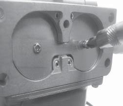
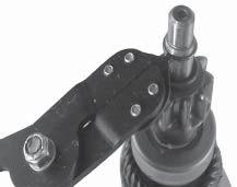
27 Check the condition of the oil. Drain the oil into a container - the oil should flow freely. Check for metal chips and other foreign particles. Sludge is a natural by-product of combustion; a small accumulation is normal. Excessive sludge formation could indicate overrich carburetion, weak ignition, overextended oil change interval or wrong weight or type of oil was used, to name a few. NOTE: It is good practice to drain oil at a location away from the workbench. Be sure to allow ample time for complete drainage. Cleaning the Engine After inspecting the external condition of the engine, clean the engine thoroughly before disassembling it. Also clean individual components as the engine is disassembled. Only clean parts can be accurately inspected and gauged for wear or damage. There are many commercially available cleaners that will quickly remove grease, oil, and grime from engine parts. When such a cleaner is used, follow the manufacturer s instructions and safety precautions carefully. Make sure all traces of the cleaner are removed before the engine is reassembled and placed into operation. Even small amounts of these cleaners can quickly break down the lubricating properties of engine oil. Basic Engine Tests Crankcase Vacuum Test A partial vacuum should be present in the crankcase when the engine is operating. Pressure in the crankcase (normally caused by a clogged or improperly assembled breather) can cause oil to be forced out at oil seals, gaskets, or other available spots. Crankcase vacuum is best measured with either a water manometer or a vacuum gauge (see Section 2). Complete instructions are provided in the kits. Section 3 Troubleshooting To test the crankcase vacuum with the manometer: 1. Insert the stopper/hose into the oil fill hole. Leave the other tube of manometer open to atmosphere. Make sure the shut off clamp is closed. 2. Start the engine and run at no-load high speed (3200 to 3750 RPM). 3. Open the clamp and note the water level in the tube. The level in the engine side should be a minimum of 10.2 cm (4 in.) above the level in the open side. If the level in the engine side is less than specified (low/no vacuum), or the level in the engine side is lower than the level in the open side (pressure), check for the conditions in the table on page Close the shut off clamp before stopping the engine. To test the crankcase vacuum with the Vacuum/ Pressure Gauge Kit (see Section 2): 1. Remove the dipstick or oil fill plug/cap. 2. Install the adapter into the oil fill/dipstick tube opening, upside down over the end of a small diameter dipstick tube, or directly into engine if a tube is not used. 3. Push the barbed fitting on the gauge solidly into the hole in the adapter. 4. Start the engine and bring it up to operating speed ( RPM). 5. Check the reading on the gauge. If the reading is to the left of 0 on the gauge, vacuum or negative pressure is indicated. If the reading is to the right of 0 on the gauge, positive pressure is present. Crankcase vacuum should be 4-10 (inches of water) If the reading is below specification, or if pressure is present, check the following table for possible causes and remedies
28 Section 3 Troubleshooting No Crankcase Vacuum/Pressure in Crankcase Possible Cause 1. Crankcase breather clogged or inoperative. 2. Seals and/or gaskets leaking. Loose or improperly torqued fasteners. 3. Piston blowby or leaky valves (confirm by inspecting components). 4. Restricted exhaust. Compression Test Some of these engines are equipped with an automatic compression release (ACR) mechanism. Because of the ACR mechanism, it is difficult to obtain an accurate compression reading. As an alternative, perform a cylinder leakdown test. Cylinder Leakdown Test A cylinder leakdown test can be a valuable alternative to a compression test. By pressurizing the combustion chamber from an external air source you can determine if the valves or rings are leaking, and how badly. Cylinder Leakdown Tester (see Section 2) is a relatively simple, inexpensive leakdown tester for small engines. The tester includes a quick disconnect for attaching the adapter hose, and a holding tool. Leakdown Test Instructions 1. Run engine for 3-5 minutes to warm it up. 2. Remove spark plug(s) and air filter from engine. 3. Rotate the crankshaft until the piston (of cylinder being tested) is at top dead center of the compression stroke. Hold the engine in this position while testing. The holding tool supplied with the tester can be used if the PTO end of the crankshaft is accessible. Lock the holding tool onto the crankshaft. Install a 3/8" breaker bar into the hole/slot of the holding tool, so it is perpendicular to both the holding tool and crankshaft PTO. Solution 1. Disassemble breather, clean parts thoroughly, check sealing surfaces for flatness, reassemble, and recheck pressure. 2. Replace all worn or damaged seals and gaskets. Make sure all fasteners are tightened securely. Use appropriate torque values and sequences when necessary. 3. Recondition piston, rings, cylinder bore, valves, and valve guides. 4. Repair/replace restricted muffler/exhaust system. If the flywheel end is more accessible, use a breaker bar and socket on the flywheel nut/ screw to hold it in position. An assistant may be needed to hold the breaker bar during testing. If the engine is mounted in a piece of equipment, it may be possible to hold it by clamping or wedging a driven component. Just be certain that the engine cannot rotate off of TDC in either direction. 4. Install the adapter into the spark plug hole, but do not attach it to the tester at this time. 5. Connect an air source of at least 50 psi to the tester. 6. Turn the regulator knob in the increase (clockwise) direction until the gauge needle is in the yellow set area at the low end of the scale. 7. Connect the tester quick-disconnect to the adapter hose while firmly holding the engine at TDC. Note the gauge reading and listen for escaping air at the carburetor intake, exhaust outlet, and crankcase breather. 8. Check your test results against the following table: 3.4
29 Section 3 Troubleshooting Leakdown Test Results Air escaping from crankcase breather... Defective rings or worn cylinder. Air escaping from exhaust system... Defective exhaust valve/improper seating. Air escaping from carburetor... Defective intake valve/improper seating. Gauge reading in low (green) zone... Piston rings and cylinder in good condition. Gauge reading in moderate (yellow) zone... Engine is still usable, but there is some wear present. Customer should start planning for overhaul or replacement. Gauge reading in high (red) zone... Rings and/or cylinder have considerable wear. Engine should be reconditioned or replaced
30 Section 3 Troubleshooting 3.6


31 Section 4 Air Cleaner and Air Intake System Air Cleaners General Most engines are equipped with a replaceable, highdensity paper air cleaner element, surrounded by an oiled foam precleaner, and housed under a flat outer cover. This is typically referred to as the standard air cleaner assembly. See Figures 4-1 and 4-4. Some engines utilize a heavy-duty style air cleaner as shown in Figure Figure 4-2. Removing Latch Style Cover. Cover Figure 4-1. Standard Air Cleaner. Standard Air Cleaner Air Cleaner Element Precleaner Service Check the air cleaner daily or before starting the engine. Check for and correct any buildup of dirt and debris, along with loose or damaged components. NOTE: Operating the engine with loose or damaged air cleaner components could allow unfiltered air into the engine, causing premature wear and failure. Figure 4-3. Removing Knob Style Cover. Precleaner Service If so equipped, wash and reoil the precleaner every 25 hours of operation (more often under extremely dusty or dirty conditions). To service the precleaner, perform the following steps: 1. Unhook the latches or loosen the retaining knob, and remove the cover. 2. Remove the foam precleaner from the paper air cleaner element. 4.1
. Allow the precleaner to air dry. 4. Saturate the precleaner with new engine oil. Squeeze out all excess oil. 5.")

. Figure 4-5.")

32 Section 4 Air Cleaner and Air Intake System 3. Wash the precleaner in warm water with detergent. Rinse the precleaner thoroughly until all traces of detergent are eliminated. Squeeze out excess water (do not wring). Allow the precleaner to air dry. 4. Saturate the precleaner with new engine oil. Squeeze out all excess oil. 5. Reinstall the precleaner over the paper air cleaner element. Seal 6. Reinstall the air cleaner cover. Secure the cover with the two latches or the retaining knob. Element Cover Wing Nut Figure 4-6. Removing Elements. Precleaner Element Figure 4-4. Air Cleaner Components. Figure 4-7. Removing Rubber Seal from Bracket. Paper Element Service (Standard Type) Every 100 hours of operation (more often under extremely dusty or dirty conditions), replace the paper element. Follow these steps: 1. Unhook the latches or loosen the retaining knob, and remove the cover. 2. Remove the wing nut, element cover, and paper element with precleaner (if so equipped). Figure 4-5. Removing Element Cover Wing Nut. 3. Remove the precleaner (if so equipped) from the paper element. Service the precleaner as described in "Precleaner Service". 4. Do not wash the paper element or use pressurized air, as this will damage the element. Replace a dirty, bent, or damaged element with a genuine Kohler element. Handle new elements carefully; do not use if the sealing surfaces are bent or damaged. 4.2
33 Section 4 Air Cleaner and Air Intake System 5. Check the seal for any damage or deterioration. Replace as necessary. See Figure Reinstall the air cleaner cover and secure with the latches or the retaining knob. 6. Reinstall the seal, paper element, precleaner, element cover, and wing nut. NOTE: Make sure the correct depth air cleaner element and rubber seal are used for the engine spec involved. Some engines use a deeper or extra capacity air cleaner and a longer rubber seal. 4 Figure 4-8. Exploded View of Standard Air Intake System Components. 4.3


34 Section 4 Air Cleaner and Air Intake System Air Cleaner Element Cover and Seal - Make sure element cover is not bent or damaged. Make sure the wing nut and seal are in place to ensure the element is sealed against leakage. Air Cleaner Base - Make sure the base is secured tightly to the carburetor and not cracked or damaged. Breather Tube - Make sure the tube is attached to both the air cleaner base and the breather cover. Figure 4-9. Bracket Retaining Screw. NOTE: Damaged, worn or loose air cleaner components can allow unfiltered air into the engine causing premature wear and failure. Tighten or replace all loose or damaged components. Rear Mounting Screws Complete Disassembly and Reassembly - Standard Type If the base plate on the standard type has to be removed, proceed as follows: 1. Remove air cleaner components as described earlier. 2. Remove the hex flange screws securing the bracket and base. See Figures 4-9 and Remove the bracket. Figure Rear Mounting Screws (Used with Plastic Intake Manifold). 3. Pinch the sealing collar on the breather hose and push it down through the hole in the air cleaner base. Carefully feed the upper section of the breather tube down through the base. See Figure Remove the base and gasket. 5. Reverse the procedure to reinstall new or serviced components. Torque screws to 9.9 N m (88 in. lb.). Heavy-Duty Air Cleaner Figure Breather Tube. Air Cleaner Components Whenever the air cleaner cover is removed, or the paper element or precleaner are serviced, check the following: General The heavy-duty air cleaner consists of a cylindrical housing, typically mounted to a bracket off the upper valve cover screws, and connected with a formed rubber hose to an adapter on the carburetor or throttle body/intake manifold (EFI units). The air cleaner housing contains a paper element and inner element, designed for longer service intervals. The system is CARB/EPA certified and the components should not be altered or modified in any way. 4.4
, replace the paper element and check the inner element. Follow these steps. 1.")

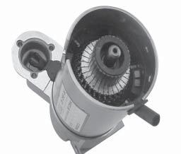
35 Section 4 Air Cleaner and Air Intake System Figure Heavy-Duty Air Cleaner. To Service Every 250 hours of operation (more often under extremely dusty or dirty conditions), replace the paper element and check the inner element. Follow these steps. 1. Unhook the two retaining clips and remove the end cap from the air cleaner housing. 2. Pull the air cleaner element out of the housing. See Figure Do not wash the paper element and inner element or use compressed air, this will damage the elements. Replace dirty, bent or damaged elements with new genuine Kohler elements as required. Handle the new elements carefully; do not use if the sealing surfaces are bent or damaged. 5. Check all parts for wear, cracks, or damage. Replace any damaged components. 6. Install the new inner element, followed by the outer element. Slide each fully into place in the air cleaner housing. 7. Reinstall the end cap so the dust ejector valve is down, and secure with the two retaining clips. See Figure Removal 1. Remove the upper valve cover screws on each side, securing the main bracket, and loosen the hose clamp on the adapter inlet, or remove the adapter mounting screws. 2. Lift the entire air cleaner assembly off the engine. Disassemble or service as required. 4 Element Inner Element Installation 1. Install the main mounting bracket with the center section up and the cutout around the carburetor, aligning the mounting holes with the four upper valve cover holes. 2. Install and torque the four valve cover mounting screws to specified torque value. Figure Removing Elements. 3. Reconnect the hose to the adapter and tighten the clamp, or install a new adapter gasket (if the adapter was separated from the carburetor), and torque the mounting fasteners to 7.3 N m (65 in. lb.). 3. After the element is removed, check the condition of the inner element. It should be replaced whenever it appears dirty, typically every other time the main element is replaced. Clean the area around the base of the inner element before removing it, so dirt does not get into the engine. NOTE: Adapter configurations may vary depending on engine and application involved. Two adapters are shown in Figure
 or 25 755 21-S (gold), are recommended to aid inspection and cleanout of the cooling fins. See Figure 4-15.")


36 Section 4 Air Cleaner and Air Intake System *Cleanout kits, Kohler Part No S (black) or S (gold), are recommended to aid inspection and cleanout of the cooling fins. See Figure NOTE: Operating the engine with a blocked grass screen, dirty or plugged cooling fins, and/or cooling shrouds removed, will cause engine damage due to overheating. Figure Adapters for Heavy-Duty Air Cleaners. Air Intake/Cooling System To ensure proper cooling, make sure the grass screen, cooling fan fins, and external surfaces of the engine are kept clean at all times. Every 100 hours of operation (more often under extremely dusty or dirty conditions), remove the blower housing and other cooling shrouds. *Clean the cooling fins and external surfaces as necessary. Make sure the cooling shrouds are reinstalled. Figure Cleanout Kit Installed on Blower Housing. 4.6
37
38

39
40


41


42

43


44
45
46
47


48


49


50


51


52


53


54
55
56

57


58


59
60

61 Section 5A LPG Fuel Systems Section 5A LPG Fuel Systems WARNING: Explosive Fuel! LPG is extremely flammable, is heavier than air, and tends to settle in low areas where a spark or flame could ignite the gas. Do not start or operate this engine in a poorly ventilated area where leaking gas could accumulate and endanger the safety of persons in the area. Proper service and repair of LPG fuel systems requires qualified technicians and special equipment. Many states require special licensing or certification for LPG repair shops and/or technicians. Check state and local regulations before attempting any adjustment, service, or repair of the LPG system or components. Faulty repairs by unqualified or underqualified personnel can have very serious ramifications. The information in this segment is for the exclusive use of qualified LPG service providers. 5A LPG Fuel System Components The typical liquid withdrawal LPG fuel system consists of the following components: LPG Fuel Tank (Liquid Withdrawal) Electric Lock-Off/Filter Assembly Vaporizer LPG Regulator (Combination Primary/Secondary/Vacuum Lock-Off) LPG Carburetor High Pressure Fuel Line(s) Vacuum Line Fuel Line Vaporizer Vacuum Line Lock-Off/Filter Assembly LPG Regulator Figure 5A-1. 5A.1
62 Section 5A LPG Fuel Systems Operation In a liquid withdrawal system, the Liquefied Petroleum Gas (LPG) is released from the bottom of the supply tank under high pressure. Upon opening the shut-off valve on the tank, liquid fuel travels out through the high pressure line to the electric lock-off/ filter assembly. The lock-off opens internally when the key switch is turned on, permitting filtered fuel to flow to the vaporizer. The vaporizer is mounted in the flow of the discharged cooling air. It absorbs heat from the cooling air and transfers it to the fuel, changing the liquefied petroleum to a vapor or gaseous state, while partially stepping down the fuel pressure. The gas/ vapor flows under this decreased pressure to the regulator where it is further reduced to a usable, regulated pressure. The regulator, activated by intake manifold vacuum, controls fuel flow to the carburetor. In the venturi of the carburetor, the fuel vapor is mixed with incoming air from the air cleaner in the correct ratio for efficient combustion. Troubleshooting Checklist If the engine starts hard, runs roughly, or stalls, check the following areas. Make sure the LPG fuel tank is filled and shut-off valve is fully opened. Make sure fuel is reaching the carburetor. Make sure the air cleaner element and precleaner are clean and all components are fastened securely. Make sure the ignition, governor, exhaust, throttle, and choke control systems are all operating properly. Check compression. If engine continues to start hard, run roughly, or stall after these checks have been made, use the following troubleshooting guide. Engine cranks but will not start 1. LPG fuel tank closed, low, or empty. 2. Lock-off not opening electrically, preventing fuel flow to vaporizer. 3. Fuel filter (located inside lock-off) dirty or blocked. 4. Insufficient vacuum signal, regulator not opening. a. Vacuum line between carburetor and regulator cracked, leaking, kinked, or pinched. b. Carburetor loose. c. Intake manifold loose or leaking. d. Excessive internal engine wear. 5. Faulty regulator. a. Primary valve not opening. b. Diaphragm spring adjustment incorrect. c. Idle adjustment screw incorrectly set. d. Vent(s) blocked/restricted. 6. Restricted/blocked fuel line. 7. Blocked carburetor fuel circuit. 8. Loose/leaking fuel enrichment hose (Impco carburetor system). Hard starting, runs roughly, or stalls at idle speed 1. LPG fuel tank low. 2. Vacuum line between carburetor and regulator pinched, cracked, or leaking. 3. Carburetor idle speed set too low (should be at least 1200 RPM). 4. Carburetor idle circuit restricted. 5. Dirty/restricted air cleaner. 6. Dirty/restricted lock-off filter. 7. Frozen/malfunctioning regulator. Check/adjust primary pressure. 8. Excessive external load on engine. 9. Excessive internal wear. 10. Loose/leaking fuel enrichment hose (Impco carburetor system). Irregular or inconsistent idle 1. Improper operation/adjustment of regulator, idle adjustment screw, throttle opening, and/or engine governor. 2. Secondary valve in regulator not closing. Readjust idle screw (couterclockwise) so valve can close fully against seat. 3. Loose/leaking vacuum line. 4. Loose carburetor mounting and/or line connections. 5. Damaged diaphragm(s) within regulator. 6. Debris in regulator. Flush debris from drain plug or remove regulator from system, disassemble body and remove debris. 7. Dirt or debris in carburetor. Remove carburetor, disassemble and clean/service as required. If venturi (Impco carburetor) removal is performed, mark its orientation to the carburetor body for proper reinstallation. 8. Loose/leaking fuel enrichment hose (Impco carburetor system). 5A.2
. Low power 1. Air cleaner or exhaust system dirty/restricted. 2. Low fuel. 3.")

63 Engine stalls during operation 1. No fuel. 2. Faulty lock-off or blocked filter. 3. Improper governor setting. 4. Damaged diaphragms within regulator. 5. Vacuum line leaking, loose, or pinched. 6. Restricted fuel line. 7. Loose/leaking fuel enrichment hose (Impco carburetor system). Low power 1. Air cleaner or exhaust system dirty/restricted. 2. Low fuel. 3. Rich gas condition (flooding) through regulator. a. Dirty/restricted valves in regulator. b. Damaged primary diaphragm in regulator. 4. No fuel. a. Electric lock-off not opening, filter blocked, or restriction within fuel line. b. Leaking, loose, or cracked vacuum line from carburetor to regulator. c. Leaking, or loose intake system components. d. Regulator primary valve not opening. e. Secondary, or vacuum lock-off diaphragm within regulator leaking. f. Low pressure rubber hose kinked. g. Frozen regulator. 5. Improper ignition timing. 6. Loose/incorrect throttle lever/clamp bracket positioning. 7. Loose or incorrectly positioned high speed throttle plate stop. Engine runs lean 1. Electrical problem causing intermittent lock-off operation, or lock-off is faulty. 2. Filter in lock-off dirty or restricted. 3. Restriction in fuel system. 4. Idle holes plugged; dirt in fuel delivery channels. 5. Carburetor fuel circuit restriction. 6. Loose/leaking fuel enrichment hose (Impco carburetor system). High fuel consumption 1. Fuel leak. Check lines, connections, and system components for leaks with soapy water. Fix any leaks immediately. 2. Incorrectly set regulator, or leakage from valves in regulator. Readjust, service, or replace regulator as required. 3. Dirty air cleaner or precleaner. 4. Choke plate in carburetor not opening completely. LPG Carburetor Adjustments Section 5A LPG Fuel Systems General The LPG carburetor and regulator are designed to deliver the correct fuel-to-air mixture to the engine under all operating conditions. The high and low idle fuel mixture settings are preset at the factory, and cannot be adjusted. These engines are equipped with an Impco or Nikki carburetor. See Figure 5A-2 and 5A-3. Although both carburetors function similarly, each is unique and should not be interchanged. Fuel Enrichment Hose Idle Speed Fuel Inlet Adjusting Screw Figure 5A-2. Impco Carburetor. Choke Plate/Shaft Assembly Rear Plug with Sealing Washer Fuel Inlet Load Block Assembly Plastic Bushing Figure 5A-3. Nikki Carburetor. Venturi Retaining Screw Transfer Chamber Cover Vacuum Port Idle Speed Adjusting Screw Impco carburetors also incorporate the use of an external Load Block assembly, which controls the final fuel flow to the carburetor for all throttle positions except idle. See Figure 5A-2. Calibrated and flow-matched to the carburetor, it functions similarly to preset fuel mixture settings in other carburetors. The load block assembly is not available separately, nor is any internal servicing permitted or possible. If a problem is encountered and determined to be caused by the load block, the carburetor should be replaced. 5A 5A.3

 in or out, to obtain a low idle speed of 1200 RPM (± 75 RPM), or set to application specifications.")
64 Section 5A LPG Fuel Systems High Altitude Operation The standard carburetor calibrations will provide proper operation up to altitudes of 1500 m (5000 ft.). No internal changes are necessary or available for either carburetor. NOTE: Carburetor adjustments should be made only after the engine has warmed up. Idle Speed Adjustment 1. Start the engine and run at half throttle for 5 to 10 minutes. Check that the throttle and choke (Nikki carburetor) plates can open fully. 2. Place the throttle control into the idle or slow position. Turn the low idle speed adjusting screw (See Figure 5A-2 or 5A-3) in or out, to obtain a low idle speed of 1200 RPM (± 75 RPM), or set to application specifications. Check the speed using a tachometer. Impco Carburetor 1. Turn off fuel supply at tank. 2. Remove the air cleaner, breather hose, fuel line, vacuum hose, choke, and throttle linkages. Remove the mounting hardware, carburetor, and gaskets from the engine. Discard the gaskets. 3. The carburetor venturi may be removed for inspection and appropriate cleaning. a. Remove the four screws securing the air cleaner adapter and gasket to the carburetor. See Figure 5A-4. NOTE: The actual low idle speed (RPM) depends on the application. Refer to the equipment manufacturer s recommendations. The low idle speed for basic engines is 1200 RPM. LPG Fuel System Component Service LPG Carburetor - Cleaning The carburetor may be cleaned if necessary. Removal from the engine and limited disassembly will aid in cleaning. NOTE: Impco Carburetor: Do not loosen or alter the mounted position of the clamping brackets and/or stop collar on the throttle shaft. Each is preset, in correlation to a specific position of the throttle plate (shaft), or acts as a stop. None of these attached components, including the throttle plate or shaft, requires disassembly or removal for any carburetor servicing. All the components on the throttle shaft should be left intact. If the settings of any one of these is inadvertently loosened or altered, each must be checked/reset, or performance and operation will be affected. Refer to the procedure included in the reassembly/installation sequence to check or reset. Figure 5A-4. b. Important: Mark a small line on the outer edge of the venturi for proper orientation and reinstallation later. c. Loosen the venturi retaining screw on the side of the carburetor body and lift out the venturi. See Figure 5A-5. Figure 5A-5. 5A.4


65 Section 5A LPG Fuel Systems 4. Inspect the overall condition of the fuel enrichment hose attached to the carburetor. It must be free of cracks, deterioration, and damage. Disconnect the fuel enrichment hose from the carburetor fittings to clean or check condition as required. See Figure 5A-6. Replace with a new Kohler high pressure hose (LP rated) if the condition is questionable in any way. Secure new hose using new clamps. Figure 5A Clean all parts as required, use a good carburetor cleaner, following the manufacturer's instructions. Blow clean, compressed air through all the passages. Do not poke or probe into the load block assembly as damage can be done, resulting in serious operational problems. See Figure 5A-7. Nikki Carburetor 1. Turn off fuel supply at tank. 2. Remove the air cleaner, breather hose, fuel line, vacuum hose, choke, and throttle linkages. Remove the nuts, carburetor, and gaskets from the engine. Discard the gaskets. 3. Remove the fuel transfer chamber cover by removing the three screws. See Figure 5A-3. Carefully remove the cover and gasket. Discard the gasket. 4. The main jet is fixed and nonadjustable, but may be accessed for cleaning by removing the rear plug and sealing washer. Discard the washer. 5. In order to clean the off-idle transfer passages and carburetor thoroughly, use a good carburetor cleaner and follow the manufacturer's instructions. Blow clean, compressed air through the passages and make sure all are open before reassembling. Do not use wire or metal objects to clean passages or carburetor body. LPG Carburetor - Inspection 1. Inspect the carburetor body and removable venturi (Impco carburetor) for cracks, holes, and other wear or damage. 2. Check the choke shaft (Nikki carburetor only) and the throttle shaft for wear and free movement. 5A NOTE: Do not attempt to disassemble or remove either shaft from the carburetor body, including the mounted clamp brackets on Impco style carburetors. The screws, attaching the choke and throttle plate to their respective shafts are staked or bonded to prevent loosening. The plate(s) and shaft(s) are not available separately. If detrimental wear or damage is found in any of the parts, the carburetor should be replaced. Figure 5A-7. 5A.5

. 3. Install a new adapter gasket and mount the air cleaner adapter onto the carburetor with the four screws. Torque the screws to 4.0 N m (36 in. lb.). 4. Install a new carburetor gasket onto the intake manifold adapter, followed by the carburetor.")
66 Section 5A LPG Fuel Systems LPG Carburetor - Reassembly Impco Carburetor 1. Slide the venturi into the carburetor body, aligning the position mark made prior to removal. Correctly installed, the discharge holes should not be visible from the top. Idle Speed Clamp Bracket Position 1. Counting the number of turns, back the idle speed adjustment screw off (counterclockwise), so only 1 to 1 1/2 of the threads are visible. See Figure 5A Secure with the venturi retaining screw. Torque the screw to 4.0 N m (36 in. lb.). 3. Install a new adapter gasket and mount the air cleaner adapter onto the carburetor with the four screws. Torque the screws to 4.0 N m (36 in. lb.). 4. Install a new carburetor gasket onto the intake manifold adapter, followed by the carburetor. Install and finger tighten the mounting fasteners. 5. Connect the Z end of the throttle linkage and the dampening spring to the throttle clamp bracket on the throttle shaft. Attach the opposite end of linkage and spring to the governor lever. NOTE: The clamp brackets and stop collar mounted on the throttle shaft should still be in their original positions (See Figure 5A-2), and not require any readjustment/ resetting. Continue with steps 6 and 7. If the mounted position of any one of these was affected or changed, it will be necessary to check and reset the position of each before proceeding. Follow the complete instructions listed after step 7, then continue with steps 6 and 7. Idle Speed Clamp Bracket Mounting Screw Figure 5A-8. Backing Off Idle Speed Screw. 2. Loosen the clamp bracket mounting screw, and pivot the throttle shaft to fully close the throttle plate. See Figure 5A Manually move the governor lever toward the carburetor as far as it will go. 7. Check that the throttle plate is now fully open or reposition the carburetor slightly on the mounting screws so it is fully open. Torque the mounting screws to 9.9 N m (88 in. lb.). Instructions for Checking/Positioning the Clamp Brackets Mounted on the Throttle Shaft Use only if the position or mounting of the clamp bracket(s) has been disturbed. Figures show the carburetor removed from the engine for clarity. Figure 5A-9. Closing Throttle Plate. 3. Hold the throttle plate closed and rotate the clamp bracket until the end of the screw contacts the stop. Insert a mm (0.001 in.) feeler gauge between the carburetor housing and the side of the clamp bracket to set the endplay, then tighten the mounting screw securely. See Figure 5A-10. 5A.6
 feeler gauge between the side of the stop collar and the carburetor housing, then check or set the position of the stop collar.")


67 Section 5A LPG Fuel Systems 3. Insert a mm (0.001 in.) feeler gauge between the side of the stop collar and the carburetor housing, then check or set the position of the stop collar. The head of the mounting screw must be in contact with the carburetor boss from the back (hose/fitting) side, preventing any further rotation over center. Set or adjust the stop collar as required. See Figure 5A-12. Figure 5A-10. Tightening Idle Speed Clamp Mounting Screw. 4. Reset the idle speed adjustment screw back to the original position. High Speed/Stop Collar Position 1. Make sure the idle speed clamp position has already been checked or properly set. 2. Rotate and hold the throttle shaft so the throttle plate is fully open/perfectly vertical. See Figure 5A-11. High Speed Stop Collar Figure 5A-12. Adjusting/Setting Stop Collar. 4. Tighten the screw securely. NOTE: High Speed Stop Collar After the idle speed clamp bracket and the high speed stop collar positions have been set, check that the throttle shaft pivots freely without binding or restriction. Throttle Linkage Clamp Bracket Position Carburetor must be assembled to engine with linkage attached to set this position. 1. The throttle linkage clamp bracket should be positioned as shown in Figure 5A-13 on the idle speed clamp bracket side of the throttle shaft. 5A Figure 5A-11. Full Throttle Position. Throttle Linkage Clamp Bracket Figure 5A-13. Throttle Linkage Clamp Bracket Position. 5A.7


 after starting and allowing sufficient warm-up time.")
68 Section 5A LPG Fuel Systems 2. Manually move the governor lever, with the throttle linkage connected, toward the carburetor as far as it will go. Hold it in this position. 3. Looking down the throat of the carburetor, check that the throttle plate is in the full throttle position and that the head of the high speed collar stop screw is in contact with the carburetor boss. If not, loosen the carburetor mounting screws and reposition the carburetor slightly. Torque the carburetor mounting screws to 9.9 N m (88 in. lb.). NOTE: If additional adjustment is required, loosen the throttle linkage clamp bracket mounting screw, set the throttle shaft to the full throttle position against the head of the stop screw, and retighten the clamp mounting screw securely. See Figure 5A Check to be sure all system connections are tight. 7. Reset idle RPM and recheck high idle (governed speed) after starting and allowing sufficient warm-up time. Electric Lock-Off/Filter Assembly - Functional Test The electric lock-off can be easily tested to verify that it is functional. Remove it from the system for testing. Using a 12 volt power supply or battery, connect one wire lead to the positive (+) lead of power supply, and touch remaining wire lead to negative (-) lead of power supply. When connection is made, an audible click should be heard indicating the opening of the lock-off. While energized, blow compressed air through it to determine if it is blocked or restricted. Figure 5A-15. Figure 5A-14. Tightening Throttle Linkage Clamp Bracket. Nikki Carburetor 1. Reinstall the rear plug with a new sealing washer. Tighten the plug securely. 2. Reinstall fuel transfer chamber cover with a new gasket. Secure with the three screws. 3. Install new carburetor mounting gasket on manifold studs, followed by the carburetor and new air cleaner base gasket. 4. Reconnect the throttle and choke linkages, and the fuel and vacuum lines. 5. Reinstall the air cleaner base and breather tube. Secure base with two mounting nuts. Torque nuts to 9.9 N m (88 in. lb.). Install the rest of the air cleaner system. Figure 5A-16. Electric Lock-Off/Filter Assembly - Filter Service The filter inside the lock-off assembly should be replaced every 500 hours of operation, or if it becomes blocked or restricted. Cleaning of the filter element is not recommended. Order a replacement filter element by the appropriate Kohler part number. 5A.8


69 Section 5A LPG Fuel Systems Vaporizer Assembly The outer surface of the vaporizer should be kept free of dirt and debris accumulation, which will cause a loss of vaporization efficiency. Visual inspection and necessary cleaning should be performed on a regular basis, more frequently under dusty or dirty conditions. The vaporizer should be disassembled, cleaned, and serviced using a rebuild kit every 1500 hours or if a problem is encountered. Figure 5A-18. Impco (Beam) Regulator. 5A Figure 5A-17. LPG Regulator The regulator controls both the pressure and flow of fuel within the LP system. It is comprised of both a primary and secondary chamber, which are dependent upon one another. Two different styles of regulators are used, based upon the system involved. The Impco (Beam) regulator is shown in Figure 5A-18, and the Nikki regulator is shown in Figure 5A-19. Although the basic design and operating principles are similar, due to system differences the regulators should not be interchanged. Figure 5A-19. Nikki Regulator. Following are separate sections covering the theory of operation and general service information for each style of regulator. Detailed service/repair instructions are included in the rebuild kit for each regulator. 5A.9
70 Section 5A LPG Fuel Systems Impco (Beam) Regulator (See Figure 5A-20) LPG vapor enters at point (A), then passes into primary area (B) at point (28), where pressure is reduced from up to 250 psi at the tank to 4.5 psi in area (B). Fuel pressure against diaphragm (2) overcomes spring (3) and as movement increases, spring (5) will close lever (6). The primary diaphragm breather (not shown in drawing) is vented to secondary chamber so that rupture of this diaphragm would direct fuel into the carburetor. Fuel now moves through passage (E), past secondary valve (25) into secondary area (C). As negative pressure (vacuum) is created at the carburetor venturi and is transmitted through the dry-gas hose to chamber (C) secondary diaphragm (12) is drawn down and contacts the secondary lever (16). Fuel will flow in proportion to air velocity through the carburetor venturi, ensuring an ideal mixture at all engine speeds. Whenever the engine is operating, the vacuum diaphragm (10) is down against the floor (H) and the spring (11) is compressed. The idle and starting adjustment is made with a tamper-resistant screw (17) which regulates the whisker wire system (not shown), opening up the secondary orifice slightly (but only when the vacuum diaphragm is drawn down). Very little vacuum is needed to start this vacuum diaphragm travel: 0.2 in. Mercury to start and 0.5 in. Mercury for full travel. The instant the engine stops rotating, loss of vacuum in section (D) releases diaphragm (10) causing bumper (K) to push against secondary lever (16), overcoming action of whisker wire and ensuring 100% lock-off Figure 5A B 25 E H D 28 A 1. 1/8-27 NPT Plug 2. Primary Diaphragm Assembly 3. Primary Spring 4. Expansion Plug 5. Secondary Diaphragm Spring 6. Primary Lever Assembly 7. Fillister Head Screw 8. Primary Pivot Pin 9. Torx Head Screw 10. Vac Lock Diaphragm Assembly 11. Vac Lock Spring K C Secondary Diaphragm 13. Pan Head Screw 14. Secondary Lever Spring 15. Secondary Pivot Pin 16. Secondary Lever Assembly 17. Adjustment Screw 18. Pan Head Screw 19. Expansion Plug 20. Diaphragm Gasket 21. Split Lock Washer This patented Beam design will lock off primary pressures up to five times in excess of normal and permits starting without priming or choking. 5A.10
71 Nikki Regulator Primary Chamber (See Figure 5A-21) The primary chamber reduces the high pressure fuel flow from the tank and vaporizer down to approximately 4 psi. Fuel flowing from the vaporizer enters the inlet of the regulator under approximately 76 kpa (11 psi) of pressure. There it is delivered to the primary chamber (3) through the clearance between the primary valve (1) and valve seat (2). As fuel continues to flow and the primary chamber approaches 29 kpa (4 psi), the primary diaphragm (4) overcomes the tension of the diaphragm spring (5). As the diaphragm (4) and contact button (6) move up, the primary lever spring (8) pushes the primary lever (7) up, in turn closing the primary valve (1) and stopping the flow of fuel. As fuel is consumed and the pressure in the primary chamber drops below 29 kpa (4 psi), the diaphragm spring (5) tension will be greater than the fuel pressure, causing the primary diaphragm (4) to be pushed down. This causes the contact button (6), to push the primary lever (7) down, in turn opening the primary valve (1) and admitting more fuel. In this manner, the pressure within the primary chamber is maintained at a relatively constant 29 kpa (4 psi) Figure 5A-21. Primary Chamber. 9 8 To Secondary Chamber 1. Primary Valve 6. Contact Button 2. Primary Valve Seat 7. Primary Valve Lever 3. Primary Chamber 8. Primary Lever Spring 4. Primary Diaphragm 9. Primary Pressure 5. Primary Diaphragm Spring Adjustment Fuel Inlet Section 5A LPG Fuel Systems Nikki Regulator Secondary Chamber (See Figure 5A-22) The secondary chamber further reduces the fuel pressure from the 29 kpa (4 psi) of the primary chamber to near 0 kpa (0 psi) pressure, to prevent excessive fuel flow to the carburetor. Fuel enters the secondary chamber (13) through the clearance between the secondary valve (11) and the valve seat (12). While the engine is operating, and fuel is being drawn from the secondary chamber, the secondary diaphragm (14) is raised by atmospheric pressure, simultaneously lifting the secondary valve lever (16), opening the secondary valve (11), allowing fuel to flow. When the engine is running at idle, there may not be enough vacuum created in the carburetor venturi to overcome the tension of the secondary diaphragm spring (15), and the secondary diaphragm cannot open the valve. Under those conditions, the idle adjusting screw (18), and balance spring (19) are used to apply just enough pressure on the diaphragm (14) to maintain sufficient fuel flow for idle operation. The vacuum lock-off mechanism is located in the secondary chamber. When the engine is running, manifold vacuum above the diaphragm (17) draws it up, so the secondary valve can function normally. When the engine is stopped, manifold vacuum is terminated, and the diaphragm relaxes and pushes down on the secondary valve lever, preventing any fuel flow or leakage through the regulator From Primary Chamber To Intake Manifold To Carburetor Secondary Valve 16. Secondary Valve Lever 12. Secondary Valve Seat 17. Vacuum Lock-Off 13. Secondary Chamber Diaphragm 14. Secondary Diaphragm 18. Idle Adjust Screw 15. Secondary Diaphragm Spring 19. Balance Spring Figure 5A-22. Secondary Chamber. 17 5A 5A.11

72 Section 5A LPG Fuel Systems Preventative Maintenance The regulator is preset at the factory and generally requires no further adjustment. No periodic service is required. Over time, depending on fuel quality, operating environment, and system performance, fuel deposits can accumulate inside the regulator. Those regulators containing a drain plug (Nikki) should be drained every 500 hours to remove any accumulated deposits. See Figure 5A-23. Regulator Service Every 1500 hours it is recommended that disassembly, cleaning, and resetting of the regulator be performed using the regulator rebuilding kit available. Specific instructions are included in the rebuilding kit. Perform the regulator service following the instructions provided. As all adjustments and settings must be reset using specific test equipment, this must be performed by qualified LP personnel only. Impco (Beam) Regulator Service Kohler repair kit S should be used to service the regulator every 1500 hours, or whenever cleaning and servicing is required. Nikki Regulator Service Kohler repair kit S should be used every 1500 hours. Regulator Drain Plug Figure 5A-23. Regulator Drain Plug (Some Models). 1. Turn supply valve off, run engine out of fuel, and turn off ignition switch. 2. Disconnect and ground the spark plug leads. 3. Remove the 1/8" pipe plug from bottom of regulator and drain any accumulated deposits. See Figure 5A Reinstall plug using pipe sealant with Teflon (Loctite 592 or equivalent) on threads and tighten securely. If required, a replacement plug is available as Kohler Part No. X S. 5A.12
73
74
75


76

77


78


79
80


81
82


83
84

85


86


87


88

89

90


91


92


93


94


95


96


97
98
99
100
101
102
103
104
105
106
107
108
109
110
111
112
113
114
115
116
117
118
119


120


121


122
123
124
125 Section 7 Retractable Starter WARNING: Spring Under Tension! Retractable starters contain a powerful, recoil spring that is under tension. Always wear safety goggles when servicing retractable starters and carefully follow instructions in this section for relieving spring tension. To Remove Starter 1. Remove the five hex flange screws securing the starter to the blower housing. 2. Remove the starter. Hex Flange Screws Starter Housing Handle with Rope Retainer To Install Starter 1. Install the retractable starter onto the blower housing, leaving the five hex flange screws slightly loose. Spring and Keeper Rope 7 2. Pull the starter handle out until the pawls engage in the drive cup. Hold the handle in this position and tighten the screws securely. Rope Replacement The rope can be replaced without complete starter disassembly. Pulley Brake Washer Brake Spring Pawl Springs Pawls Pawl Retainer 1. Remove the starter from the blower housing. 2. Pull the rope out approximately 12 in. and tie a temporary (slip) knot in it to keep it from retracting into the starter. See Figure 7-2. Center Screw Plain Washer Drive Cup Figure 7-1. Retractable Starter - Exploded View. 7.1

 until the spring is tight (approximately 6 full turns of pulley). 8.")
126 Section 7 Retractable Starter Slipknot Handle Keep Pulley from Rotating Rope Guide Bushing Knot Rope Hole in Pulley Rope Retainer Figure 7-2. Removing Starter Handle. 3. Remove the rope retainer from inside the starter handle. Untie the single knot and remove the rope retainer and handle. 4. Hold the pulley firmly and untie the slipknot. Allow the pulley to rotate slowly as the spring tension is released. 5. When all spring tension on the starter pulley is released, remove the rope from the pulley. 6. Tie a single knot in one end of the new rope. 7. Rotate the pulley counterclockwise (when viewed from pawl side of pulley) until the spring is tight (approximately 6 full turns of pulley). 8. Rotate the pulley clockwise until the rope hole in the pulley is aligned with the rope guide bushing of the starter housing. Figure 7-3. Installing Rope. 10. Tie a slipknot approximately 12 in. from the free end of rope. Hold the pulley firmly and allow it to rotate slowly until the slipknot reaches the guide bushing of the housing. 11. Slip the handle and rope retainer onto the rope. Tie a single knot at the end of the rope. Install the rope retainer into the starter handle. 12. Untie the slipknot and pull on the handle until the rope is fully extended. Slowly retract the rope into the starter. When the spring is properly tensioned, the rope will retract fully and the handle will stop against the starter housing. Pawls (Dogs) Replacement To replace the pawls, follow disassembly steps 1-4 and reassembly steps 3-8 on the following pages. A pawl repair kit is available which includes the following components: NOTE: Do not allow the pulley/spring to unwind. Enlist the aid of a helper if necessary, or use a C-clamp to hold the pulley in position. 9. Insert the new rope through the rope hole in the starter pulley and the rope guide bushing of the housing. See Figure 7-3. Qty Description Pawl Retainer Center Screw Pawl (Dog) Spring Brake Spring Starter Pawl (Dog) Brake Washer Washer 7.2

 2.")

127 Section 7 Retractable Starter Disassembly WARNING: Spring Under Tension! Do not remove the center screw from the starter until the spring tension is released. Removing the center screw before releasing spring tension, or improper starter disassembly, can cause the sudden and potentially dangerous release of the spring. Follow these instructions carefully to ensure personal safety and proper starter disassembly. Make sure adequate face protection is worn by all persons in the area. Pawl Spring Brake Spring and Brake Washer Pawls 1. Release the spring tension and remove the handle and the starter rope. (Refer to Rope Replacement, steps 2 through 5 on pages 7.1 and 7.2.) 2. Remove the center screw, washer, and pawl retainer. See Figure Remove the brake spring and the brake washer. See Figure Carefully note the positions of the pawls and pawl springs before removing them. Remove the pawls and pawl springs from the starter pulley. Figure 7-5. Brake Spring and Washer, Pawls, and Pawl Springs. 5. Rotate the pulley clockwise 2 full turns. This will ensure the spring is disengaged from the starter housing. 6. Hold the pulley in the starter housing. Invert the pulley/housing so the pulley is away from your face, and away from others in the area. 7. Rotate the pulley slightly from side to side and carefully separate the pulley from the housing. See Figure Center Screw and Washer Pawl Retainer If the pulley and the housing do not separate easily, the spring could be engaged in the starter housing, or there is still tension on the spring. Return the pulley to the housing and repeat step 5 before separating the pulley and housing. Housing Pulley Figure 7-4. Center Screw, Washer and Pawl Retainer. Figure 7-6. Removing Pulley from Housing. 7.3


128 Section 7 Retractable Starter 8. Note the position of the spring and keeper assembly in the pulley. See Figure 7-7. Remove the spring and keeper assembly from the pulley as a package. WARNING: Spring Under Tension! Do not remove the spring from the keeper. Severe personal injury could result from the sudden uncoiling of the spring. Outer Spring Hook Rope Hole in Pulley Reassembly 1. Make sure the spring is well lubricated with grease. Place the spring and keeper assembly inside the pulley (with spring towards pulley). See Figure Install the pulley assembly into the starter housing. See Figure 7-8. Make sure the pulley is fully seated against the starter housing. Do not wind the pulley and recoil spring at this time. Pulley & Spring Spring & Keeper Figure 7-7. Position of Spring and Keeper in Pulley. Inspection and Service 1. Carefully inspect the rope, pawls, housing, center screw, and other components for wear or damage. 2. Replace all worn or damaged components. Use only genuine Kohler replacement parts as specified in the Parts Manual. All components shown in Figure 7-1 are available as service parts. Do not use nonstandard parts. 3. Do not attempt to rewind a spring that has come out of the keeper. Order and install a new spring and keeper assembly. 4. Clean all old grease and dirt from the starter components. Generously lubricate the spring and center shaft with any commercially available bearing grease. Housing Figure 7-8. Installing Pulley and Spring into Housing. 3. Install the pawl springs and pawls into the starter pulley. See Figure 7-9. Pawl Pawl Spring Figure 7-9. Installing Pawls and Pawl Springs. 7.4
129 Section 7 Retractable Starter 4. Place the brake washer in the recess in starter pulley; over the center shaft. 5. Lubricate the brake spring sparingly with grease. Place the spring on the plain washer. Make sure the threads in the center shaft remain clean, dry, and free of grease and oil. 7. Tension the spring and install the rope and handle as instructed in steps 6 through 12 under Rope Replacement on page Install the starter to the engine blower housing as instructed in To Install Starter on page Apply a small amount of Loctite No. 271 to the threads of the center screw. Install the center screw with the washer and retainer to the center shaft. Torque the screw to N m (65-75 in. lb.)
130 Section 7 Retractable Starter 7.6
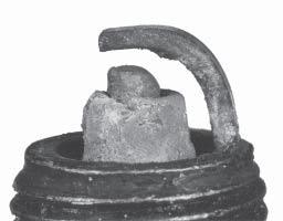
131 Section 8 Electrical System and Components Section 8 Electrical System and Components This section covers the operation, service, and repair of the electrical system components. Systems and components covered in this section are: Spark Plugs Battery and Charging System Electronic Ignition Systems (CD and DSAI) Electric Starter Spark Plugs Engine misfire or starting problems are often caused by a spark plug that has improper gap or is in poor condition. The engine is equipped with the following spark plugs: Type: The standard spark plug is a Champion RC12YC (Kohler Part No S). Natural gas (NG) or RFI compliant engines use Champion XC12YC (Kohler S) spark plug. A high-performance spark plug, Champion Platinum 3071 (used on Pro Series engines, Kohler Part No S) is also available. Equivalent alternate brand plugs can also be used. Gap: 0.76 mm (0.030 in.) all except NG CD Fixed 0.51 mm (0.020 in.) NG CD Fixed Thread Size: 14 mm Reach: 19.1 mm (3/4 in.) Hex Size: 15.9 mm (5/8 in.) Spark Plug Service Every 200 hours of operation, remove each spark plug. Check its condition and either reset the gap or replace with a new plug as necessary. To service the plugs, perform the following steps: 1. Before removing each spark plug, clean the area around the base of the plug to keep dirt and debris out of the engine. 2. Remove the plug and check its condition. See Inspection following this procedure. Replace the plug if necessary. NOTE: Do not clean spark plug in a machine using abrasive grit. Some grit could remain in the spark plug and enter the engine causing extensive wear and damage. 3. Check the gap using a wire feeler gauge. Adjust the gap to 0.76 mm (0.030 in.) for all except NG CD Fixed or 0.51 mm (0.020 in.) for NG CD Fixed, by carefully bending the ground electrode. See Figure 8-1. Wire Gauge Spark Plug Ground Electrode Figure 8-1. Servicing Spark Plug. Gap 4. Reinstall the spark plug into the cylinder head and torque to N m (18-22 ft. lb.). Inspection Inspect each spark plug as it is removed from the cylinder head. The deposits on the tip are an indication of the general condition of the piston rings, valves, and carburetor. Normal and fouled plugs are shown in the following photos: 8 8.1


132
133
134
135
136


137
138 Section 8 Electrical System and Components The pulse generated by the input coil of the ignition module (L1, Figure 8-5) is fed to the input of the conditioning circuit. The conditioning circuit shapes this pulse, putting it in a useable form for the additional circuits. This pulse starts the charge pump, which charges a capacitor in a linear fashion that can be directly related to the engine speed. At the same time the pulse resets the delay circuit for length of the pulse width. The comparator is off during this period and no output is generated. As soon as the original pulse drops back to zero, the capacitor in the delay circuit begins to charge. When the charge on the delay capacitor exceeds the charge on the charge pump capacitor the comparator changes state, activating the pulse generator. This pulse turns ON the CD ignition module semiconductor. Energy is then transferred to the secondary of the output transformer (T1, Figure 8-5). The high voltage pulse generated here is delivered to the spark plug, causing arcing of the spark gap and igniting the fuel-air mixture in the combustion chamber. As the trigger pulse is generated, all associated circuits are reset, their capacitors discharged. The longer it takes the delay circuit to surpass the charge pump capacitor voltage, the later the trigger pulse will occur, retarding the timing accordingly. Troubleshooting CD Ignition Systems The CD ignition systems are designed to be trouble free for the life of the engine. Other than periodically checking/replacing the spark plugs, no maintenance or timing adjustments are necessary or possible. Mechanical systems do occasionally fail or break down however, so the following troubleshooting information is provided to help you get to the root of a reported problem. CAUTION: High-Energy Electric Spark! The CD ignition systems produce a high-energy electric spark, but the spark must be discharged, or damage to the system can result. Do not crank or run an engine with a spark plug lead disconnected. Always provide a path for the spark to discharge to ground. Reported ignition problems are most often due to poor connections. Before beginning the test procedure, check all external wiring. Be certain all ignition-related wires are connected, including the spark plug leads. Be certain all terminal connections fit snugly. Make sure the ignition switch is in the run position. NOTE: The CD ignition systems are sensitive to excessive load on the kill lead. If a customer complains of hard starting, low power, or misfire under load, it may be due to excessive draw on the kill circuit. Perform the appropriate test procedure. Test Procedure for SMART-SPARK TM Ignition Systems The following procedures are provided for troubleshooting ignition problems on SMART- SPARK equipped engines. They will allow you to isolate and pinpoint the failed component(s). Special Tools Required: Hand Tachometer Tester* (see Section 2) Automotive timing light Multi-meter (digital) Specifications Required: Spark plug gap 0.76 mm (0.030 in.) Ignition module air gap 0.28/0.33 mm ( in.), 0.30 mm (0.012 in.) nominal *NOTE: Ignition tester (see Section 2) must be used to test ignition on these engines. Use of any other tester can result in inaccurate findings. Battery on unit must be fully charged and properly connected before making any of these tests (a battery that is hooked up or charged backward will crank the engine, but it won t have spark). Be sure drive is in neutral and all external loads are disconnected. drive is in neutral and all external loads are disconnected. Test 1. Isolate and verify the trouble is within the engine ignition system. 1. Locate the plug connectors where the wiring harnesses from the engine and equipment are joined. Separate the connectors and remove the white kill lead from the engine connector. Rejoin the connectors and position or insulate the kill lead terminal so it cannot touch ground. Try to start** the engine to verify whether the reported problem is still present. a. If the problem is gone, the electrical system on the unit is suspect. Check the key switch, wires, connections, safety interlocks, etc. 8.8
139 Section 8 Electrical System and Components b. If the problem persists the condition is associated with the ignition or electrical system of the engine. Leave the kill lead isolated until all testing is completed. Test 3. Check for timing advance. **NOTE: If the engine starts or runs during any of the testing, you may need to ground the kill lead to shut it down. Because you have interrupted the kill circuit, it may not stop using the switch. Test 2. Test for spark. 1. With the engine stopped, disconnect one spark plug lead. Connect the spark plug lead to post terminal of spark tester (see Section 2), and attach tester clip to a good engine ground. NOTE: If two testers are available, testing can be performed simultaneously for both cylinders. However, if only one tester is available, two individual tests must be performed. The side not being tested must have the spark plug lead connected or grounded. Do not crank the engine or perform tests with one spark plug lead disconnected and not grounded or permanent system damage may occur. Figure Make a line near the edge of the flywheel screen with a marking pen or narrow tape. 2. Connect an automotive timing light to cylinder that had good spark. 2. Crank the engine over, establishing a minimum of RPM, and observe tester(s) for spark On a twin cylinder engine, repeat the spark test on the opposite cylinder if cylinders are being tested individually. a. If both cylinders have good spark, but the engine runs poorly, install new spark plugs gapped at 0.76 mm (0.030 in.) and retest engine performance. If problem persists, go to Test 3. b. If one cylinder had good spark, but the other cylinder had no spark or intermittent spark, go to Test 3. c. If there was no spark or intermittent spark on both cylinders, go to Test 4. Figure Run the engine at idle and use the timing light beam to locate the line on the screen. Draw a line on the blower housing adjacent to the line on the screen. Accelerate to full throttle and watch for movement of the line on the screen relative to the line on the blower housing. If both cylinders had good spark, repeat the test on the other cylinder. a. If the line on the screen moved away from the line on the blower housing during acceleration, the SAM is working properly. If it didn t move away, go to Test

140
141


142


143


144
145
146
147


148
149
150
151
152


153


154


155
156
157
158
159
160


161

162


163


164

165


166


167


168
169


170


171


172


173


174

175
176
 Disconnect the spark plug lead(s). 2) Disconnect negative (-) battery cable from battery.")
177 Section 9 Disassembly Section 9 Disassembly WARNING: Accidental Starts! Disabling engine. Accidental starting can cause severe injury or death. Before working on the engine or equipment, disable the engine as follows: 1) Disconnect the spark plug lead(s). 2) Disconnect negative (-) battery cable from battery. General Clean all parts thoroughly as the engine is disassembled. Only clean parts can be accurately inspected and gauged for wear or damage. There are many commercially available cleaners that will quickly remove grease, oil, and grime from engine parts. When such a cleaner is used, follow the manufacturer s instructions and safety precautions carefully. Make sure all traces of the cleaner are removed before the engine is reassembled and placed into operation. Even small amounts of these cleaners can quickly break down the lubricating properties of engine oil. Typical Disassembly Sequence The following sequence is suggested for complete engine disassembly. The sequence can be varied to accommodate options or special equipment. 1. Disconnect spark plug leads. 2. Shut off fuel supply. 3. Drain oil from crankcase and remove oil filter. 4. Remove muffler. 5. Remove air cleaner assembly. 6. Remove fuel pump. 7. Remove control panel (if so equipped). 8. Remove throttle and choke controls. 9. Remove external governor controls. 10. Remove carburetor. 11. Remove Oil Sentry (if so equipped). 12. Remove electric starter motor. 13. Remove outer baffles and blower housing. 14. Remove inner baffles and breather cover. 15. Remove valve covers. 16. Remove ignition modules. 17. Remove intake manifold. 18. Remove spark plugs. 19. Remove cylinder heads and hydraulic lifters. 20. Remove grass screen and fan. 21. Remove flywheel. 22. Remove stator and backing plates. 23. Remove closure plate assembly. 24. Remove camshaft. 25. Remove connecting rods with pistons and rings. 26. Remove crankshaft. 27. Remove governor cross shaft. 28. Remove flywheel end oil seal. Disconnect Spark Plug Leads 1. Disconnect the leads from the spark plugs. See Figure 9-1. NOTE: Pull on boot only, to prevent damage to spark plug lead. Figure 9-1. Disconnect Both Spark Plug Leads. Shut Off Fuel Supply Drain Oil from Crankcase and Remove Oil Filter 1. Remove the oil fill cap, dipstick, and one of the oil drain plugs


178 Section 9 Disassembly 3. Remove and discard the oil filter. See Figure 9-5. Figure 9-2. Removing Dipstick from Tube. Figure 9-5. Removing Oil Filter. Figure 9-3. Removing Oil Fill Cap from Cover. Figure 9-4. Removing Oil Drain Plug. Figure 9-6. Removing Oil Filter Adapter Nipple. 2. Allow ample time for the oil to drain from the crankcase and oil filter. 9.2


179 Section 9 Disassembly 4. Remove the hex flange screws securing the bracket and base. See Figure 9-8. Two additional rear screws must be removed if the engine contains a rear air cleaner support bracket. See Figure 9-9. Figure 9-8. Removing Air Cleaner Base Retainer. Figure 9-7. Removing Oil Cooler. 4. An oil cooler is standard equipment on some models and an option on others. It may be a cast aluminum housing, part of the oil filter adapter, or attached to the blower housing, separated from the oil filter adapter. If so equipped, remove the adapter and the cooler. See Figures 9-6 and 9-7. Remove Muffler 1. Remove the exhaust system and attaching hardware from the engine. On engines equipped with a port liner, remove it now. Remove Air Cleaner Assembly Standard Air Cleaner 1. Unhook the latches or loosen the knob and remove the cover. Refer to Section Remove the wing nut from the element cover. 3. Remove the element cover, the air cleaner element with precleaner and the stud seal. Figure 9-9. Rear Air Cleaner Bracket Screws. 5. Remove the bracket then remove the base and gasket while carefully pulling the rubber breather tube through the base. See Figure Figure Removing Breather Tube from Base
. 4.")
, or the four hex flange nuts (two-barrel carburetor models), securing the adapter or elbow. See Figure 9-12.")


180 Section 9 Disassembly Mounting Screws Figure Removing Tube from Breather Cover. 6. Remove the rubber breather tube from the breather cover. See Figure Heavy Duty Air Cleaner 1. Disconnect the breather hose from the fitting in adapter or elbow. Figure Air Cleaner Bracket Mounting Screws (Two-Barrel Model Pictured). 4. Remove the heavy-duty air cleaner as an assembly from the engine. See Figure Remove the two screws (one-barrel carburetor models), or the four hex flange nuts (two-barrel carburetor models), securing the adapter or elbow. See Figure Breather Hose Mounting Nuts Figure Breather Hose, Mounting Nuts, and Adapter Elbow (Two-Barrel Model Pictured). 3. Remove the screws securing the main support bracket for air cleaner to the valve covers. On two-barrel carburetor models, remove the two mounting screws into the top of intake manifold. Unhook the choke return spring if equipped. Do not lose any of the hardware. See Figure Figure Removing Heavy Duty Air Cleaner Assembly (Two-Barrel Model Pictured). Remove Fuel Pump WARNING: Explosive Fuel! Gasoline is extremely flammable and its vapors can explode if ignited. Store gasoline only in approved containers, in well ventilated, unoccupied buildings, away from sparks or flames. Do not fill the fuel tank while the engine is hot or running, since spilled fuel could ignite if it comes in contact with hot parts or sparks from ignition. Do not start the engine near spilled fuel. Never use gasoline as a cleaning agent. Pulse Style Pumps 1. Disconnect the fuel lines at the carburetor and at the in-line fuel filter. See Figure


. 2.")
181 Section 9 Disassembly 3. Remove the two hex flange screws securing the fuel pump to the bracket or to the blower housing. See Figure The fuel pump body may be metal or plastic. Figure Disconnecting Fuel Inlet Line at Carburetor. Figure Removing Screws Holding Fuel Pump (Metal Bodied Pump Shown). 4. Note or mark the orientation of the fuel pump, then remove the fuel pump with lines attached as shown in Figure Figure Disconnecting Pulse Line from Crankcase. 9 Figure Remove Fuel Pump and Lines. Mechanical Fuel Pump The mechanical style fuel pump is part of the valve cover assembly. See Figure Figure Disconnecting Pulse Line from Valve Cover (Early Models). 2. Disconnect the pulse (vacuum) line from the crankcase, or from the valve cover on earlier models. See Figures 9-16 and Disconnect the fuel lines at the pump outlet and at the in-line fuel filter. 2. The fuel pump will be removed with the valve cover. Refer to the valve cover removal procedure. 9.5
 1. Disconnect the Oil Sentry Indicator Light wires.")
. 2.")


182 Section 9 Disassembly Figure Mechanical Fuel Pump. Remove Control Panel (If So Equipped) 1. Disconnect the Oil Sentry Indicator Light wires. 2. Disconnect the choke control cable from the control bracket. Figure Rear Air Cleaner Bracket (Some Models). 2. Mark the spring hole locations and disconnect the spring from the governor lever. See Figure Disconnect the throttle control cable or shaft. 4. Remove the panel from the blower housing. Remove Throttle & Choke Controls 1. Remove the four hex flange screws securing the control bracket and rear air cleaner bracket (some models) to the cylinder heads. See Figures 9-21 and Figure Disconnecting Spring from Bracket. 3. Remove the choke linkage from the choke actuator lever and carburetor. See Figure Figure Removing Control Bracket. Figure Disconnecting Choke Linkage from Actuator Lever. 9.6

.")


183 Section 9 Disassembly Remove External Governor Controls 1. Loosen the hex flange nut and remove the governor lever from the cross shaft. See Figure Leave lever attached to the throttle linkage and lay assembly on the top of the crankcase. 2. One-Barrel Carburetor Models Only: Remove the two carburetor mounting screws. See Figure Two-Barrel Carburetor Models Only: If required use two hex flange nuts locked together and remove the two carburetor mounting studs on the starter side of the intake manifold and one of the studs on the oil filter side. Pivot the carburetor to clear the breather cover fitting and pressure switch (if equipped). Remove the carburetor, throttle linkage, choke linkage, and the governor lever as an assembly. Figure Removing Governor Lever. Remove Carburetor WARNING: Explosive Fuel! Gasoline is extremely flammable and its vapors can explode if ignited. Store gasoline only in approved containers, in well ventilated, unoccupied buildings, away from sparks or flames. Do not fill the fuel tank while the engine is hot or running, since spilled fuel could ignite if it comes in contact with hot parts or sparks from ignition. Do not start the engine near spilled fuel. Never use gasoline as a cleaning agent. 1. Disconnect the fuel shut-off solenoid lead and ground lead, if equipped. See Figure Figure Removing Carburetor Mounting Screws. 3. Remove the carburetor, throttle linkage and governor lever as an assembly. See Figure Ground Lead Figure Remove Ground Lead (Two-Barrel Model Pictured). Figure Removing Carburetor Assembly with Governor Lever Attached. 4. Remove the carburetor gasket. 9.7
 1. Disconnect the lead from the Oil Sentry switch.")

 from the terminal plug as shown in Figure 9-32.")
. 3. The rectifier-regulator does not have to be detached from the blower housing.")
184 Section 9 Disassembly 5. If necessary, the carburetor, throttle linkage and governor lever can be separated. Reattach the bushings to the linkage following separation to avoid losing them. Remove Oil Sentry (If So Equipped) 1. Disconnect the lead from the Oil Sentry switch. Remove Outer Baffles and Blower Housing 1. Disconnect the plug from the rectifier-regulator on the blower housing. See Figure Remove the Oil Sentry switch from the breather cover. See Figure Figure Disconnecting Plug from Rectifier- Regulator. Figure Removing Oil Sentry Switch from Breather Cover. Remove Electric Starter Motor 1. Disconnect the leads from the starter. 2. Use the tip of the dipstick or a similar small flat tool to bend the locking tang, then remove the B+ (center lead) from the terminal plug as shown in Figure This will allow the blower housing to be removed without disturbing the wiring harness. 2. Remove the two hex flange screws. See Figure Figure Remove B+ Lead from Terminal Plug. Figure Removing Electric Starter Motor. 3. Remove the starter assembly and any spacers (if used). 3. The rectifier-regulator does not have to be detached from the blower housing. If the engine is equipped with SMART-SPARK the SAM module should be removed from the cylinder baffle or blower housing. See Figure The module willing hang loose as part of the wiring harness. 9.8


 hex flange screws securing the outer baffles.")
 for reassembly. See Figure 9-34. 9 Figure 9-36. Removing Metal Grass Screen. 7.")

185 Section 9 Disassembly Figure Removing Outer Baffles. 5. Remove the outer baffles on both sides. See Figure On engines equipped with a metal grass screen, remove the screen before removing the blower housing. See Figure Plastic grass screens can be removed after the blower housing is removed. Figure Removing the Spark Advance Module (Applicable Models). 4. Remove the three (each side) hex flange screws securing the outer baffles. Note the location of any lifting strap and position of the two short screws (one each side on bottom) for reassembly. See Figure Figure Removing Metal Grass Screen. 7. Remove the lower blower housing screw and washer securing the rectifier-regulator ground lead or grounding strap. 8. Two-Barrel Carburetor Models Only: Remove the two screws securing the debris shield to the blower housing. The wiring harness is attached to the underside of shield. See Figure Figure Note Location of Two Short Screws. 9.9


186 Section 9 Disassembly Debris Shield Mounting Screws Figure Debris Shield Details (Two-Barrel Carburetor Model Shown). 9. Remove the remaining hex flange screws and detach the blower housing. See Figure Figure Removing Fasteners Holding Baffle and Breather Cover. 2. Remove both inner baffles. See Figure Disconnect the plug from the key switch in the blower housing if engine is so equipped. Figure Removing Inner Baffles. Figure Removing Blower Housing. Remove Inner Baffles and Breather Cover The inner (valley) baffles are attached at one corner using the same fasteners as the breather cover. See Figure Remove the two hex flange screws securing the inner baffles. 3. Remove the two remaining screws holding the breather cover to the crankcase. See Figure Pry under the protruding edge of the breather cover with a screwdriver to break the RTV or gasket seal. See Figure Do not pry on the sealing surfaces as it could cause damage resulting in leaks. Most engines use a formed gasket rather than RTV sealant. 9.10
. See Figure 9-42.")


187 Section 9 Disassembly 7. Remove the hex flange screw, breather reed retainer and breather reed. See Figure Figure Breaking Breather Cover Seal. 5. Remove the breather cover and gasket (if used). See Figure Figure Removing Breather Reed. Figure Removing Breather Cover. 6. Remove the breather filter from chamber. See Figure Remove Valve Covers Three valve cover designs have been used. The earliest type used a gasket and RTV sealant between the cover and sealing surface of the cylinder head. The second type had a black O-Ring installed in a groove on the underside of the cover and may have metal spacers in the bolt holes. The latest design uses a brown O-Ring, and the bolt holes spacers are molded in place. 1. Remove the four hex flange screws securing each valve cover. Note the position of any attached brackets or lifting straps. 2. Remove the valve covers, valve cover gaskets or O-Rings and any brackets or lifting straps. Note which side of the engine has the oil fill and or fuel pump valve cover. See Figure Figure Removing Breather Filter. Figure Removing Valve Covers. 9.11


188 Section 9 Disassembly Remove Ignition Modules 1. Disconnect the lead(s)* from each ignition module. See Figure *Modules for non- SMART-SPARK ignition systems have only one kill lead. 3. Leave the wiring harness attached to the manifold. Aluminum Intake Manifold Plastic Intake Manifold Figure Disconnecting Leads from Ignition Modules. 2. Rotate the flywheel so the magnet is away from the modules. 3. Remove the mounting screws and ignition modules. Note the position of ignition modules. Two-Barrel Intake Manifold Figure Position of SMART-SPARK Ignition Module. Remove Intake Manifold 1. Remove the four hex flange screws securing the intake manifold to the cylinder heads. Note which screws hold the wiring clamps. Figure Removing Intake Manifold. 2. Remove the intake manifold and the intake manifold gaskets (aluminum intake manifolds) or O-Rings (plastic intake manifolds). See Figure


 should only be removed if damaged or if cylinder reconditioning is necessary. Once removed, they must be replaced.")
189 Section 9 Disassembly Hex Flange Screw Figure Bolt Wiring Harness Detail. Remove Spark Plugs 1. Remove the spark plug from each cylinder head. Hex Flange Nut and Washer Figure Removing Spark Plugs. Remove Cylinder Heads and Hydraulic Lifters NOTE: Cylinder heads are retained using either hex flange screws or hex flange nuts and washers on studs. Do not interchange or mix components, as the cylinder heads may have different machining, unique to each fastening method. 1. Remove the four hex flange screws or hex nuts and washers securing each cylinder head. See Figure Discard the screws or nuts and washers once removed. Do not reuse. Studs (if present) should only be removed if damaged or if cylinder reconditioning is necessary. Once removed, they must be replaced. Figure Removing Cylinder Head Fasteners. 2. Mark the position of the push rods as either intake or exhaust and cylinder 1 or 2. Push rods should always be reinstalled in the same positions. 3. Carefully remove the push rods, cylinder heads and head gaskets. See Figure


190 Section 9 Disassembly Hex Flange Screw Style Mounting Figure Removing Hydraulic Lifter. Stud and Hex Flange Nut Style Mounting Figure Removing Cylinder Head Assembly. 4. Remove the lifters from the lifter bores. Use a Hydraulic Lifter Tool. Do not use a magnet to remove lifters. Mark the lifters by location, as either intake or exhaust and cylinder 1 or 2. Hydraulic lifters should always be reinstalled in the same position. See Figures 9-53 and Figure Mark Position of Hydraulic Lifters. NOTE: The exhaust lifters are located on the output shaft side of the engine while the intake lifters are located on the fan side of the engine. The cylinder head number is embossed on the outside of each cylinder head. See Figure Figure Match Marks on Cylinder Barrel and Heads. 9.14


191 Section 9 Disassembly Disassemble Cylinder Heads 1. Remove the two hex flange screws, rocker arm pivots and rocker arms from the cylinder head. See Figure Once the valve spring is compressed, remove the following items. See Figures 9-58 and Valve spring keepers Valve spring retainers Valve springs Valve spring caps Intake and exhaust valves (mark position) Valve stem seals (intake valve only) Valve Seal Figure Removing Rocker Arms. 2. Compress the valve springs using a valve spring compressor. See Figure Figure Intake Valve Seal Location. NOTE: These engines use valve stem seals on the intake valves. Use a new seal whenever valve is removed or if the seal is deteriorated in any way. Never reuse an old seal. 4. Repeat the above procedure for the other cylinder head. Do not interchange parts from one cylinder head to the other. 9 Figure Removing Valves with Valve Spring Compressor. Valve Remove Grass Screen and Fan 1. Small metal retainers are typically attached on three of the seven mounting posts for positive retention of the plastic grass screen. Use a hookend tool next to the post and pull outward to separate each of the small metal retainers. Then unsnap the fan from the remaining mounting posts. See Figure Keepers Retainer Spring Figure Valve Train Components. Cap 9.15

 to hold the flywheel and loosen the hex flange screw securing the flywheel to the crankshaft.")

192 Section 9 Disassembly Figure Removing Plastic Type Grass Screen. 2. Remove the four hex flange screws and fan. See Figure Figure Removing Flywheel Fastener Using Strap Wrench. 2. Remove the hex flange screw and washer. 3. Use a puller to remove the flywheel from the crankshaft. See Figure NOTE: Always use a flywheel puller to remove the flywheel from the crankshaft. Do not strike the crankshaft or flywheel, as these parts could become cracked or damaged. Striking the puller or crankshaft can cause the crank gear to move, affecting the crankshaft end play. Figure Removing Fan. Remove Flywheel 1. Use a flywheel strap wrench or holding tool (see Section 2) to hold the flywheel and loosen the hex flange screw securing the flywheel to the crankshaft. See Figure NOTE: Always use a flywheel strap wrench or holding tool to hold the flywheel when loosening or tightening the flywheel screw. Do not use any type of bar or wedge to hold the flywheel. Use of such tools could cause the flywheel to become cracked or damaged. Figure Removing Flywheel with a Puller. 4. Remove the woodruff key from the crankshaft. Remove Stator and Backing Plates 1. Remove the four hex flange screws securing the backing plates and stator wire bracket (if equipped). See Figure Remove the backing plates and stator wire bracket. 9.16


193 Section 9 Disassembly 2. Locate the three splitting tabs that are cast into the perimeter of the closure plate. Insert the drive end of a 1/2" breaker bar between the top splitting tab and the crankcase. Hold the handle horizontal and pull toward you to break the RTV seal. If necessary, pry at the bottom tabs also. See Figures 9-67 and Do not pry on the sealing surfaces as this could cause leaks. Carefully pull closure plate from crankcase. Figure Removing Backing Plates and Stator Wire Bracket. 2. Remove the two hex head screws and stator. See Figure Note the routing of the stator lead in the channel. Figure Location of Three Splitting Tabs. 9 Figure Removing Stator. Remove Closure Plate Assembly 1. Remove the ten hex flange screws securing the closure plate to the crankcase. See Figure Figure Breaking Seal on Top Splitting Tab. Governor Gear Assembly The governor gear assembly is located inside the closure plate. If service is required, refer to the service procedures under Governor Gear Assembly in Section 10. Oil Pump Assembly The oil pump is mounted to the inside of the closure plate. If service is required, refer to the service procedures under Oil Pump Assembly in Section 10. Figure Removing the Ten Closure Plate Fasteners. 9.17
.")


194 Section 9 Disassembly Remove Camshaft 1. Remove the camshaft and shim. See Figure Camshaft Shim Figure Mark End Cap with Cylinder Number Before Removal. Figure Removing Camshaft (Note Shim). Remove Connecting Rods with Pistons and Rings 1. Remove the two hex flange screws securing the closest connecting rod end cap. Remove the end cap. See Figure NOTE: The cylinders are numbered on the crankcase. Use the numbers to mark each end cap, connecting rod and piston for reassembly. Do not mix end caps and connecting rods. Figure Removing Connecting Rod Bolts. NOTE: If a carbon ridge is present at the top of either cylinder bore, use a ridge reamer tool to remove the ridge before attempting to remove the piston. Figure Removing Piston/Connecting Rod Assemblies. 2. Carefully remove the connecting rod and piston assembly from the cylinder bore. See Figure Repeat the above procedures for the other connecting rod and piston assembly. 9.18


195 Section 9 Disassembly Remove Crankshaft 1. Carefully pull the crankshaft from the crankcase. See Figure Note thrust washers and shims if used. Figure Removing Governor Cross Shaft Retainer (8 mm Shaft Design). Figure Removing Crankshaft. 2. Pull the cross shaft with small washer out through the inside of the crankcase. See Figure Remove Governor Cross Shaft 1. Remove the hitch pin and plain washer, or the retainer and nylon washer from the governor cross shaft. See Figures 9-74 and Figure Pulling Governor Cross Shaft. Remove Flywheel End Oil Seal 1. Remove oil seal from crankcase. See Figure Figure Removing Governor Cross Shaft Hitch Pin (6 mm Shaft Design). Figure Removing Oil Seal. 9.19
196 Section 9 Disassembly 9.20
197 Section 10 Inspection and Reconditioning Section 10 Inspection and Reconditioning This section covers the operation, inspection, and repair/reconditioning of major internal engine components. The following components are not covered in this section. They are covered in sections of their own: Air Cleaner, Section 4 Carburetor & External Governor, Section 5 Ignition, Charging & Electric Starter, Section 8 Clean all parts thoroughly. Only clean parts can be accurately inspected and gauged for wear or damage. There are many commercially available cleaners that will quickly remove grease, oil, and grime from engine parts. When such a cleaner is used, follow the manufacturer s instructions and safety precautions carefully. Make sure all traces of the cleaner are removed before the engine is reassembled and placed into operation. Even small amounts of these cleaners can quickly break down the lubricating properties of engine oil. Use an aerosol gasket remover, paint stripper, or lacquer thinner to remove any old sealant. Apply the solvent, allow time for it to work, and then brush the surface with a brass wire brush. After the old sealant is removed, clean the surface with isopropyl alcohol, lacquer thinner, or aerosol electrical contact cleaner. Do not scrape the surfaces, as any scratches, nicks, or burrs can result in leaks. See Service Bulletin 252 for further information. Refer to A Guide to Engine Rebuilding (TP-2150-A) for additional information. Measurement Guide (TP-2159-B) and Engine Inspection Data Record (TP-2435) are also available; use these to record inspection results. Automatic Compression Release (ACR) Some engines are equipped with the optional Automatic Compression Release (ACR) mechanism. The ACR lowers compression at cranking speeds to make starting easier. Operation The ACR mechanism consists of a flyweight, spring and pivoting control pin assembly attached to the gear on the camshaft. At cranking speeds (700 RPM or lower), the control pin protrudes above the exhaust cam lobe. This pushes the exhaust valve off its seat during the first part of the compression stroke. The reduced compression results in an effective compression ratio of about 2:1 during cranking. After starting, engine speed increases to over 700 RPM, and centrifugal force overcomes the force of the flyweight spring. The flyweight moves outward, pulling the arm of the control pin, so it pivots into the run position. The control pin no longer has any effect on the exhaust valve and the engine operates at full power. When the engine is stopped, the spring returns the flyweight lever and control pin assembly to the compression release position ready for the next start. Camshaft Inspection and Service Check the lobes of the camshaft for wear or damage. See Section 1 for minimum lift specifications. Inspect the cam gear for badly worn, chipped or missing teeth. Replacement of the camshaft will be necessary if any of these conditions exist. Crankshaft Inspection and Service Inspect the gear teeth of the crankshaft. If the teeth are badly worn, chipped, or some are missing, replacement of the crankshaft will be necessary
198 Section 10 Inspection and Reconditioning Inspect the crankshaft bearing surfaces for scoring, grooving, etc. Some engines have bearing inserts in the crankshaft bore of the closure plate and/or crankcase. Do not replace bearings unless they show signs of damage or are out of running clearance specifications. If the crankshaft turns easily and noiselessly, and there is no evidence of scoring, grooving, etc., on the races or bearing surfaces, the bearings can be reused. Inspect the crankshaft keyways. If they are worn or chipped, replacement of the crankshaft will be necessary. Inspect the crankpin for score marks or metallic pickup. Slight score marks can be cleaned with crocus cloth soaked in oil. If the wear limits, as stated in Specifications and Tolerances are exceeded, it will be necessary to either replace the crankshaft or regrind the crankpin to 0.25 mm (0.010 in.) undersize. If reground, a 0.25 mm (0.010 in.) undersize connecting rod (big end) must then be used to achieve proper running clearance. Measure the crankpin for size, taper, and out-of-round. Procedure to Remove Crankshaft Plug: 1. Drill a 3/16" hole through the plug in the crankshaft. 2. Thread a 3/4" or 1" long self-tapping screw with a flat washer into the drilled hole. The flat washer must be large enough to seat against the shoulder of the plug bore. See Figure Tighten the self-tapping screw until it draws the plug out of the crankshaft. Procedure to Install New Plug: 1. Use a single cylinder camshaft pin, Kohler Part No S as a driver and tap the plug into the plug bore until it seats at the bottom of the bore. Make sure the plug is tapped in evenly to prevent leakage. Self-Tapping Screw Flat Washer NOTE: If the crankpin is reground, visually check to ensure that the fillet blends smoothly with the crankpin surface. See Figure Plug High Point from Fillet Intersections Crankshaft The Fillet Must Blend Smoothly with the Bearing Journal Surface 45 Minimum This Fillet Area Must Be Completely Smooth Figure Crankpin Fillets. The connecting rod journal can be ground one size under. When grinding a crankshaft, grinding stone deposits can get caught in the oil passages, which could cause severe engine damage. Removing the crankpin plug when the crankshaft is ground provides easy access for removing any grinding deposits that may collect in the oil passages. Figure Removing Crankpin Plug. Crankcase Inspection and Service Check all gasket surfaces to make sure they are free of gasket fragments. Gasket surfaces must also be free of deep scratches or nicks. Inspect the main bearing (if so equipped) for wear or damage (refer to Section 1, Specifications, Tolerances, and Special Torque Values ). Replace the crankcase using a miniblock or short block as required. Use the following procedure to remove and replace the plug. 10.2

199 Section 10 Inspection and Reconditioning Check the cylinder bore wall for scoring. In severe cases, unburned fuel can cause scuffing and scoring of the cylinder wall. It washes the necessary lubricating oils off the piston and cylinder wall. As raw fuel seeps down the cylinder wall, the piston rings make metal to metal contact with the wall. Scoring of the cylinder wall can also be caused by localized hot spots resulting from blocked cooling fins or from inadequate or contaminated lubrication. If the cylinder bore is badly scored, excessively worn, tapered, or out-of-round, resizing is necessary. Use an inside micrometer to determine the amount of wear (refer to the Specifications, Tolerances, and Special Torque Values, in Section 1), then select the nearest suitable oversize of either 0.25 mm (0.010 in.) or 0.50 mm (0.020 in.). Resizing to one of these oversizes will allow usage of the available oversize piston and ring assemblies. First, resize using a boring bar, then use the following procedures for honing the cylinder. NOTE: Some CH25-26 engines feature POWER- BORE cylinders a special patented nickelsilicone plating process for increased power, superior oil control, reduced exhaust emission, and virtually permanent cylinder life. POWER-BORE cylinders cannot be resized or honed as described in the following procedure. If a plated cylinder bore is damaged or out of specification, use a new miniblock or short block to repair the engine. Use the following procedure for crankcases with a cast iron sleeve. Honing While most commercially available cylinder hones can be used with either portable drills or drill presses, the use of a low speed drill press is preferred as it facilitates more accurate alignment of the bore in relation to the crankshaft crossbore. Honing is best accomplished at a drill speed of about 250 RPM and 60 strokes per minute. After installing coarse stones in hone, proceed as follows: 1. Lower hone into bore and after centering, adjust so the stones are in contact with the cylinder wall. Use of a commercial cutting-cooling agent is recommended. 2. With the lower edge of each stone positioned even with the lowest edge of the bore, start drill and honing process. Move the hone up and down while resizing to prevent the formation of cutting ridges. Check the size frequently. NOTE: Kohler pistons are custom-machined to exacting tolerances. When oversizing a cylinder, it should be machined exactly 0.25 mm (0.010 in.) or 0.50 mm (0.020 in.) over the new diameter (Section 1). The corresponding oversize Kohler replacement piston will then fit correctly. 3. When the bore is within mm ( in.) of the desired size, remove the coarse stones and replace them with burnishing stones. Continue with the burnishing stones until the bore is within mm ( in.) of the desired size and then use finish stones ( grit) and polish the bore to its final size. A crosshatch should be observed if honing is done correctly. The crosshatch should intersect at approximately off the horizontal. Too flat an angle could cause the rings to skip and wear excessively, and too steep an angle will result in high oil consumption. See Figure Figure Cylinder Bore Crosshatch after Honing. 4. After resizing, check the bore for roundness, taper, and size. Use an inside micrometer, telescoping gauge, or bore gauge to take measurements. The measurements should be taken at three locations in the cylinder at the top, middle, and bottom. Two measurements should be taken (perpendicular to each other) at each of the three locations. Clean Cylinder Bore After Honing Proper cleaning of the cylinder walls following boring and/or honing is very critical to a successful overhaul. Machining grit left in the cylinder bore can destroy an engine in less than one hour of operation after a rebuild


200 Section 10 Inspection and Reconditioning The final cleaning operation should always be a thorough scrubbing with a brush and hot, soapy water. Use a strong detergent that is capable of breaking down the machining oil while maintaining a good level of suds. If the suds break down during cleaning, discard the dirty water and start again with more hot water and detergent. Following the scrubbing, rinse the cylinder with very hot, clear water, dry it completely, and apply a light coating of engine oil to prevent rusting. Measuring Piston-to-Bore Clearance Before installing the piston into the cylinder bore, it is necessary that the clearance be accurately checked. This step is often overlooked, and if the clearances are not within specifications, engine failure will usually result. NOTE: Do not use a feeler gauge to measure pistonto-bore clearance it will yield inaccurate measurements. Always use a micrometer. Use the following procedure to accurately measure the piston-to-bore clearance: 1. Use a micrometer and measure the diameter of the piston 6 mm (0.24 in.) above the bottom of the piston skirt and perpendicular to the piston pin. See Figure Piston-to-bore clearance is the difference between the bore diameter and the piston diameter (step 2 minus step 1). Flywheel Inspection Inspect the flywheel for cracks and the flywheel keyway for damage. Replace the flywheel if it is cracked. Replace the flywheel, the crankshaft, and the key if flywheel key is sheared or the keyway is damaged. Inspect the ring gear for cracks or damage. Kohler does not provide the ring gear as a serviceable part. Replace the flywheel if the ring gear is damaged. Cylinder Head and Valves Inspection and Service After cleaning, check the flatness of the cylinder head and the corresponding top surface of the crankcase, using a surface plate or piece of glass and feeler gauge as shown in Figure The maximum allowable out of flatness is mm (0.003 in.). 6 mm (0.24 in.) Measure 6 mm above the Bottom of Piston Skirt at Right Angles to Piston Pin Figure Measuring Piston Diameter. 2. Use an inside micrometer, telescoping gauge, or bore gauge and measure the cylinder bore. Take the measurement approximately 63.5 mm (2.5 in.) below the top of the bore and perpendicular to the piston pin. Figure Checking Cylinder Head Flatness. Carefully inspect the valve mechanism parts. Inspect the valve springs and related hardware for excessive wear or distortion. Check the valves and valve seat area or inserts for evidence of deep pitting, cracks, or distortion. Check clearance of the valve stems in the guides. See Figure 10-6 for valve details and specifications. 10.4
201 Section 10 Inspection and Reconditioning EXHAUST VALVE E F C B A INTAKE VALVE F E G D A EXHAUST INSERT G H D INTAKE INSERT H B A A B C D E F G H Dimension Seat Angle Insert O.D. Guide Depth Guide I.D. Valve Head Diameter Valve Face Angle Valve Margin (Min.) Valve Stem Diameter Figure Valve Details. Intake / mm (1.4562/ in.) 4 mm ( in.) 7.038/7.058 mm (0.2771/ in.) 33.37/33.63 mm (1.3138/ in.) mm ( in.) 6.982/7.000 mm (0.2749/ in.) Exhaust / mm (1.2987/ in.) 6.5 mm ( in.) 7.038/7.058 mm (0.2771/ in.) 29.37/29.63 mm (1.1563/ in.) mm ( in.) 6.970/6.988 mm (0.2744/ in.) Hard starting or loss of power accompanied by high fuel consumption may be symptoms of faulty valves. Although these symptoms could also be attributed to worn rings, remove and check the valves first. After removal, clean the valve heads, faces, and stems with a power wire brush. Then, carefully inspect each valve for defects such as a warped head, excessive corrosion, or a worn stem end. Replace valves found to be in bad condition. A normal valve and valves in bad condition are shown in the accompanying illustrations


202 Section 10 Inspection and Reconditioning Normal: Even after long hours of operation a valve can be reconditioned and reused if the face and margin are in good shape. If a valve is worn to where the margin is less than 1/32" do not reuse it. The valve shown was in operation for almost 1000 hours under controlled test conditions. Leakage: A poor grind on face or seat of valve will allow leakage resulting in a burned valve on one side only. Bad Condition: The valve depicted here should be replaced. Note the warped head; margin damaged and too narrow. These conditions could be attributed to excessive hours or a combination of poor operating conditions. Coking: Coking is normal on intake valves and is not harmful. If the seat is good, the valve could be reused after cleaning. 10.6


203 Section 10 Inspection and Reconditioning Excessive Combustion Temperatures: The white deposits seen here indicate very high combustion temperatures, usually due to a lean fuel mixture. Stem Corrosion: Moisture in fuel or from condensation are the most common causes of valve stem corrosion. Condensation occurs from improper preservation during storage and when engine is repeatedly stopped before it has a chance to reach normal operating temperatures. Replace corroded valves. 10 Gum: Gum deposits usually result from using stale gasoline. Gum is a prevalent cause of valve sticking. The cure is to ream the valve guides and clean or replace the valves, depending on their condition. Overheating: An exhaust valve subject to overheating will have a dark discoloration in the area above the valve guide. Worn guides and faulty valve springs may cause this condition. Also check for clogged air intake, and blocked fins when this condition is noted. 10.7
204 Section 10 Inspection and Reconditioning Valve Guides If a valve guide is worn beyond specifications, it will not guide the valve in a straight line. This may result in burnt valve faces or seats, loss of compression, and excessive oil consumption. To check valve guide-to-valve stem clearance, thoroughly clean the valve guide and, using a split-ball gauge, measure the inside diameter of the guide. Then, using an outside micrometer, measure the diameter of the valve stem at several points on the stem where it moves in the valve guide. Use the largest stem diameter to calculate the clearance by subtracting the stem diameter from the guide diameter. If the intake clearance exceeds 0.038/0.076 mm (0.0015/ in.) or the exhaust clearance exceeds 0.050/0.088 mm (0.0020/ in.), determine whether the valve stem or guide is responsible for the excessive clearance. The maximum (I.D.) wear on the intake valve guide is mm ( in.) while mm ( in.) is the maximum allowed on the exhaust guide. The guides are not removable but can be reamed 0.25 mm (0.010 in.) oversize. Valves with 0.25 mm oversize stems must then be used. If the guides are within limits but the valve stems are worn beyond limits, install new valves. Valve Seat Inserts Hardened steel alloy intake and exhaust valve seat inserts are press fitted into the cylinder head. The inserts are not replaceable but can be reconditioned if not too badly pitted or distorted. If cracked or badly warped, the cylinder head should be replaced. Recondition the valve seat inserts following the instructions provided with the valve seat cutter being used. A typical cutter is shown in Figure The final cut should be made with an 89 cutter as specified for the valve seat angle in Figure Cutting the proper 45 valve face angle as specified in Figure 10-6, and the proper valve seat angle (44.5, half of the full 89 angle), will achieve the desired 0.5 (1.0 full cut) interference angle where the maximum pressure occurs on the outside diameters of the valve face and seat. Valve Seat Cutter Pilot Figure Typical Valve Seat Cutter. Lapping Valves Reground or new valves must be lapped in, to provide proper fit. Use a hand valve grinder with a suction cup for final lapping. Lightly coat the valve face with a fine grade of grinding compound, then rotate the valve on its seat with the grinder. Continue grinding until a smooth surface is obtained on the seat and on the valve face. Thoroughly clean the cylinder head in soap and hot water to remove all traces of grinding compound. After drying the cylinder head, apply a light coating of SAE 10 oil to prevent rusting. Intake Valve Stem Seal These engines use valve stem seals on the intake valves. Always use a new seal when the valves are removed from the cylinder head. The seals should also be replaced if deteriorated or damaged in any way. Never reuse an old seal. Pistons and Rings Inspection Scuffing and scoring of pistons and cylinder walls occurs when internal engine temperatures approach the welding point of the piston. Temperatures high enough to do this are created by friction, which is usually attributed to improper lubrication and/or overheating of the engine. Normally, very little wear takes place in the piston boss-piston pin area. If the original piston and connecting rod can be reused after new rings are installed, the original pin can also be reused but new piston pin retainers are required. The piston pin is included as part of the piston assembly if the pin boss in the piston or the pin are worn or damaged, a new piston assembly is required. 10.8


205 Section 10 Inspection and Reconditioning Ring failure is usually indicated by excessive oil consumption and blue exhaust smoke. When rings fail, oil is allowed to enter the combustion chamber where it is burned along with the fuel. High oil consumption can also occur when the piston ring end gap is incorrect because the ring cannot properly conform to the cylinder wall under this condition. Oil control is also lost when ring gaps are not staggered during installation. When cylinder temperatures get too high, lacquer and varnish collect on pistons causing rings to stick, which results in rapid wear. A worn ring usually takes on a shiny or bright appearance. Scratches on rings and pistons are caused by abrasive material such as carbon, dirt, or pieces of hard metal. Detonation damage occurs when a portion of the fuel charge ignites spontaneously from heat and pressure shortly after ignition. This creates two flame fronts which meet and explode to create extreme hammering pressures on a specific area of the piston. Detonation generally occurs from using low octane fuels. Preignition or ignition of the fuel charge before the timed spark can cause damage similar to detonation. Preignition damage is often more severe than detonation damage. Preignition is caused by a hot spot in the combustion chamber from sources such as glowing carbon deposits, blocked cooling fins, an improperly seated valve, or wrong spark plug(s). See Figure 10-8 for some common types of piston and ring damage. Stuck, Broken Rings Abrasive Scratched Rings 10 Overheated or Deteriorated Oil Scored Piston and Rings Figure Common Types of Piston Damage. 10.9
, and 0.50 mm (0.020 in.) oversize pistons.")


206 Section 10 Inspection and Reconditioning Replacement pistons are available in STD bore size, and in 0.25 mm (0.010 in.), and 0.50 mm (0.020 in.) oversize. Replacement pistons include new piston ring sets and new piston pins. Replacement ring sets are also available separately for STD, 0.25 mm (0.010 in.), and 0.50 mm (0.020 in.) oversize pistons. Always use new piston rings when installing pistons. Never use old rings. Some important points to remember when servicing piston rings: 1. The cylinder bore must be deglazed before service ring sets are used. 2. If the cylinder bore does not need reboring and if the old piston is within wear limits and free of score or scuff marks, the old piston may be reused. 3. Remove the old rings and clean up the grooves. Never reuse old rings. 4. Before installing the new rings on the piston, place the top two rings, each in turn, in its running area in the cylinder bore and check the end gap. (See Figure 10-9.) Compare the ring gap to the specifications listed in Section 1. Figure Measuring Piston Ring Side Clearance. Install New Piston Rings To install new piston rings, proceed as follows: NOTE: Rings must be installed correctly. Ring installation instructions are usually included with new ring sets. Follow instructions carefully. Use a piston ring expander to install rings (see Figure 10-11). Install the bottom (oil control) ring first and the top compression ring last. Refer to Figure Piston Ring Piston Ring Expander Figure Installing Piston Rings. Figure Measuring Piston Ring End Gap. 5. After installing the new compression (top and middle) rings on the piston, check the piston-toring side clearance. Compare the clearance to specifications listed in Section 1. If the side clearance is greater than specified, a new piston must be used. Refer to Figure
207 Section 10 Inspection and Reconditioning Piston Ring End Gap Identification Mark Dykem Stripe Service replacement connecting rods are available in STD crankpin size and 0.25 mm (0.010 in.) undersize. The 0.25 mm (0.010 in.) undersized rod can be identified by the drilled hole located in the lower end of the rod shank. Always refer to the appropriate parts information to ensure that correct replacements are used. Hydraulic Lifters Piston Top Compression Ring Center Compression Ring Inspection Check the base surface of the hydraulic lifters for wear or damage. If the lifters need to be replaced, apply a liberal coating of Kohler lubricant (see Section 2) to the base of each new lifter before it is installed. Bleeding the Lifters To prevent a possible bent push rod or broken rocker arm, it is important to bleed any excess oil out of the lifters before they are installed. Oil Control Ring (Three-piece) Expander Figure Piston Ring Installation. Rails 1. Oil Control Ring (Bottom Groove): Install the expander and then the rails. Make sure the ends of expander are not overlapped. 2. Middle Compression Ring (Center Groove): Install the center ring using a piston ring installation tool. Make sure the identification mark is up or the dykem stripe (if contained) is to the left of the end gap. 3. Top Compression Ring (Top Groove): Install the top ring using a piston ring expender. Make sure the identification mark is up or the dykem stripe (if contained), to the left of the end gap. Connecting Rods Offset, stepped-cap connecting rods are used in all these engines. Inspection and Service Check the bearing area (big end) for excessive wear, score marks, running and side clearances (refer to Section 1, Specifications, Tolerances, and Special Torque Values ). Replace the rod and cap if scored or excessively worn. 1. Cut a mm (2-3 in.) piece from the end of an old push rod and chuck it in a drill press. 2. Lay a rag or shop towel on the table of the drill press and place the lifter, open end up, on the towel. 3. Lower the chucked push rod until it contacts the plunger in the lifter. Slowly pump the plunger two or three times to force the oil out of the feed hole in the side of the lifter. Closure Plate Assembly Inspection Inspect the oil seal in the closure plate and remove it if it is worn or damaged. Refer to Install Closure Plate Oil Seal in Section 11 for new oil seal installation. Inspect the main bearing surface for wear or damage (refer to Section 1, Specifications, Tolerances, and Special Torque Values ). Replace the closure plate assembly if required. Governor Gear Assembly Inspection Inspect the governor gear teeth. Replace the gear if it is worn, chipped, or if any teeth are missing. Inspect the governor weights. They should move freely in the governor gear


208 Section 10 Inspection and Reconditioning Disassembly The governor gear must be replaced once it is removed from the closure plate. NOTE: The governor gear is held onto the shaft by small molded tabs in the gear. When the gear is removed from the shaft, these tabs are destroyed and the gear must be replaced. Therefore, remove the gear only if absolutely necessary. 1. Remove the regulating pin and governor gear assembly. See Figure Reassembly 1. Install the locking tab thrust washer on the governor gear shaft with the tab down. 2. Position the regulating pin within the governor gear/flyweight assembly and slide both onto the governor shaft. Oil Pump Assembly Disassembly 1. Remove the two hex flange screws. 2. Remove the oil pump assembly from the closure plate. 3. Remove the oil pump rotor. 4. Remove the oil pickup by unhooking the locking clip, and pulling it free from the oil pump body. 5. If the relief valve is like that shown in Figure 10-15, drive out the pin to remove the oil pressure relief valve piston and spring. Refer to the following inspection and reassembly procedures. Figure Removing Governor Gear. 2. Remove the locking tab thrust washer located under the governor gear assembly. If the relief valve is a one-piece style, staked to the oil pump housing (See Figure 10-16) removal should not be attempted, nor is internal servicing possible. If a problem with the relief valve is encountered, the oil pump should be replaced. 3. Carefully inspect the governor gear shaft and replace it only if it is damaged. After removing the damaged shaft, press or lightly tap the replacement shaft into the closure plate to the depth shown in Figure Gear Shaft 34.0 mm ( in.) 33.5 mm ( in.) mm ( in.) Relief Valve Pickup Figure Oil Pump, Oil Pickup, and Relief Valve (Original Style). Figure Governor Shaft Press Depth


 All Reinstallations: 6.7 N m (60 in. lb.) 5.")
209 Section 10 Inspection and Reconditioning 3. Install the rotor. 4. Install the oil pump body to the closure plate and secure with the two hex flange screws. Torque the hex flange screws as follows: a. Install fastener into location No. 1 and lightly tighten to position pump. b. Install fastener into location No. 2 and fully torque to the recommended value. Relief Valve Pickup Figure Oil Pump, Oil Pickup, and One-Piece Relief Valve (Later Style). c. Torque fastener in location No. 1 to the recommended value. Inspection Inspect the oil pump housing, gear, and rotors for nicks, burrs, wear, or any visible damage. If any parts are worn or damaged, replace the oil pump. Inspect the oil pressure relief valve piston. It should be free of nicks or burrs. Check the spring for wear or distortion. The free length of the spring should be approximately 47.4 mm (1.8 in.). Replace the spring if it is distorted or worn. See Figure Oil Pump Torque Sequence First Time Installation:10.7 N m (95 in. lb.) All Reinstallations: 6.7 N m (60 in. lb.) 5. After torquing, rotate the gear and check for freedom of movement. Make sure there is no binding. If binding occurs, loosen the screws, reposition the pump, retorque the hex flange screws and recheck the movement. 10 Piston Spring Roll Pin Figure Oil Pressure Relief Valve Piston and Spring. Reassembly 1. Install the pressure relief valve piston and spring. 2. Install the oil pickup to the oil pump body. Lubricate the O-Ring with oil and make sure it remains in the groove as the pickup is being installed
210 Section 10 Inspection and Reconditioning Governor Cross Shaft Oil Seal If the governor cross shaft seal is damaged and/or leaks, replace it using the following procedure. Remove the oil seal from the crankcase and replace it with a new one. Install the new seal to the depth shown in Figure using a seal installer. 2.0 mm ( in.) Governor Cross Shaft Seal Figure Installing Cross Shaft Oil Seal

211


212


213


214


215
216


217


218


219


220


221


222


223


. See Figure 11-48. Figure 11-49. Installing Ignition Module. 2. On engines equipped with SMART-SPARK both modules are installed the same way - with the two tabs out.")
224 Section 11 Reassembly 5. Repeat the above steps for the remaining cylinder. Do not interchange parts from the cylinder heads. Install Ignition Modules 1. Rotate the flywheel to position the magnet away from the ignition module bosses. Figure Using Spanner Wrench to Lift Rocker Arm Over Push Rod. 6. Rotate the crankshaft to check for free operation of the valve train. Check the clearance between the valve spring coils at full lift. Minimum allowable clearance is 0.25 mm (0.010 in.). Check Assembly Important: Rotate the crankshaft a minimum of two revolutions to check longblock assembly and overall proper operation. Install Spark Plugs 1. Use new Champion (or equivalent) spark plugs. 2. Set the gap at 0.76 mm (0.030 in.) for all except natural gas with CD fixed ignition, or 0.51 mm (0.020 in.) for natural gas with CD fixed ignition. 3. Install new plugs and torque to N m (18-22 ft. lb.). See Figure Figure Installing Ignition Module. 2. On engines equipped with SMART-SPARK both modules are installed the same way - with the two tabs out. See Figure On engines are not equipped with SMART- SPARK the modules are installed with the spark plug lead wire from module always away from the cylinder. On #1 cylinder, the single kill tab should be towards you. See Figure On #2 cylinder, the single kill tab should be away from you (in). 3. Install each ignition module to the crankcase bosses with the two screws (hex flange or allen head, based on model). Slide the modules up as far away from the flywheel as possible and snug the screws to hold them in that position. 4. Rotate the flywheel to position the magnet directly under one ignition module. 5. Insert a 0.30 mm (0.012 in.) flat feeler gauge between the magnet and the ignition module. See Figure Loosen the screws enough to allow the magnet to pull the module down against the feeler gauge. Figure Installing Spark Plugs


225


226


227


228


229


230


231
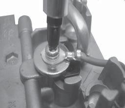


232
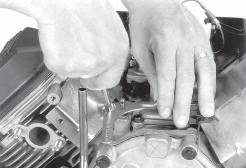


233


234
235


236


237


238


239


240


241
VERTICAL CRANKSHAFT SERVICE MANUAL COMMAND CV17-750
 VERTICAL CRANKSHAFT SERVICE MANUAL COMMAND CV17-750 Contents Section 1. Safety and General Information... Section 2. Tools & Aids... Section 3. Troubleshooting... Section 4. Air Cleaner and Air Intake
ECH630-ECH749 HORIZONTAL CRANKSHAFT
 SERVICE MANUAL ECH630-ECH749 HORIZONTAL CRANKSHAFT Contents Section 1. Safety and General Information... Section 2. Tools & Aids... Section 3. Troubleshooting... Section 4. Air Cleaner and Air Intake
HORIZONTAL CRANKSHAFT SERVICE MANUAL COMMAND CH18-745
 HORIZONTAL CRANKSHAFT SERVICE MANUAL COMMAND CH18-745 Section 1 Safety and General Information CH18-745 Section 1 Safety and General Information 1 Safety Precautions To ensure safe operation please read
SERVICE MANUAL COMMAND CH18-745
 www.mymowerparts.com HORIZONTAL CRANKSHAFT SERVICE MANUAL COMMAND CH18-745 Section 1 Safety and General Information CH18-745 Section 1 Safety and General Information 1 Safety Precautions To ensure safe
VERTICAL CRANKSHAFT SERVICE MANUAL COMMAND CV17-745
 VERTICAL CRANKSHAFT SERVICE MANUAL COMMAND CV17-745 Contents Section 1. Safety and General Information... Section 2. Special Tools... Section 3. Troubleshooting... Section 4. Air Cleaner and Air Intake
HORIZONTAL CRANKSHAFT CH270 CH395 CH440
 SERVICE MANUAL HORIZONTAL CRANKSHAFT CH270 CH395 CH440 Contents Section 1. Safety and General Information... Section 2. Tools & Aids... Section 3. Troubleshooting... Section 4. Air Cleaner and Air Intake
Contents. Section 1. Safety and General Information... Section 2. Tools & Aids... Section 3. Troubleshooting...
 Contents Section 1. Safety and General Information... Section 2. Tools & Aids... Section 3. Troubleshooting... Section 4. Air Cleaner and Air Intake System... Section 5. Fuel System and Governor... Section
COLT 2310, 2510, AND 2712 COM PACT TRACTORS CHAPTER 9 TROUBLESHOOTING AND ANALYSIS
 COLT 2310, 2510, AND 2712 COM PACT TRACTORS CHAPTER 9 TROUBLESHOOTING AND ANALYSIS 9-A-1 UPON RECEIVING ANENGINE FORRE- PAIR. Learn the history of the unit from the customer. While the customer is present
LIQUID-COOLED HORIZONTAL CRANKSHAFT SERVICE MANUAL AEGIS LH
 LIQUID-COOLED HORIZONTAL CRANKSHAFT SERVICE MANUAL AEGIS LH630-775 Contents Section 1. Safety and General Information... Section 2. Tools & Aids... Section 3. Troubleshooting... Section 4. Air Cleaner
VERTICAL CRANKSHAFT SERVICE MANUAL COURAGE SV COURAGE PRO SV
 VERTICAL CRANKSHAFT SERVICE MANUAL COURAGE SV710-740 COURAGE PRO SV810-840 Contents Section 1. Safety and General Information... Section 2. Tools & Aids... Section 3. Troubleshooting... Section 4. Air
CARBURETOR SERVICE INFORMATION TROUBLESHOOTING THROTTLE VALVE DISASSEMBLY THROTTLE VALVE INSTALLATION...
 11 CARBURETOR SERVICE INFORMATION... 11-2 TROUBLESHOOTING... 11-2 THROTTLE VALVE DISASSEMBLY... 11-3 THROTTLE VALVE INSTALLATION... 11-4 CARBURETOR REMOVAL... 11-5 AUTO BYSTARTER... 11-6 FLOAT CHAMBER...
SPECIFICATIONS TEST AND ADJUSTMENT SPECIFICATIONS SPECIFICATIONS ENGINE FD620D, K SERIES
 ENGINE FD620D, K SERIES SPECIFICATIONS SPECIFICATIONS TEST AND ADJUSTMENT SPECIFICATIONS Engine Oil Pressure Sensor Activates............................... 98 kpa (14.2 psi) Oil Pressure While Cranking
5. FUEL SYSTEM FUEL SYSTEM 5-0
 5 FUEL SYSTEM 5-0 SERVICE INFORMATION GENERAL INSTRUCTIONS SERVICE INFORMATION...5-1 CARBURETOR INSTALLATION...5-9 TROUBLESHOOTING...5-1 PILOT SCREW ADJUSTMENT...5-10 CARBURETOR REMOVAL...5-2 AUTO BYSTARTER...5-3
SECTION 4 - FUEL SYSTEMS AND CARBURETION
 SECTION - FUEL SYSTEMS AND CARBURETION FUEL SYSTEMS - - - - - - - - - - - - - - - - - - - - - - - - - - - - - - - - - - - - - - - - - - - - - - - - - - - - - - - - - - - - - -62 FUEL PUMP - - - - - - -
12. CARBURETOR 12-0 CARBURETOR VITALITY 50
 12 12 CARBURETOR SERVICE INFORMATION (2-STROKE)... 12-2 SERVICE INFORMATION (4-STROKE)... 12-3 THROTTLE VALVE (2-STROKE)... 12-5 CARBURETOR (2-STROKE)... 12-7 AIR SCREW ADJUSTMENT (2-STROKE)... 12-13 REED
WEBER CARBURETOR TROUBLESHOOTING GUIDE
 This guide is to help pinpoint problems by diagnosing engine symptoms associated with specific vehicle operating conditions. The chart will guide you step by step to help correct these problems. For successful
5. FUEL SYSTEM 5-0 FUEL SYSTEM MXU 250R/300R
 5 FUEL SYSTEM 5 SERVICE INFORMATION------------------------------------------------ 5-2 TROUBLESHOOTING----------------------------------------------------- 5-3 FUEL TANK -----------------------------------------------------------------
5. FUEL SYSTEM 5-0 FUEL SYSTEM UXV 500
 5 FUEL SYSTEM 5 SERVICE INFORMATION------------------------------------------------ 5-02 TROUBLESHOOTING----------------------------------------------------- 5-03 FUEL TANK -----------------------------------------------------------------
SPECIFICATIONS TEST AND ADJUSTMENT SPECIFICATIONS SPECIFICATIONS ENGINE FD620D, K SERIES
 TEST AND ADJUSTMENT Engine Oil Pressure Sensor Activates............................... 98 kpa (14.2 psi) Oil Pressure While Cranking (Minimum).......................... 28 kpa (4 psi) Oil Pressure.....................................
February 26, ch.12.notebook. Ch. 12. Preventative Maintenance and Troubleshooting. Feb 23 5:03 PM
 Ch. 12 Preventative Maintenance and Troubleshooting Feb 23 5:03 PM 1 Why PM? preventive maintenance certain maintenance tasks must be performed regularly to keep an engine working properly helps premature
HOW - TO EMISSION CONTROL BASICS EMISSION CONTROL BASICS
 HOW - TO EMISSION CONTROL BASICS EMISSION CONTROL BASICS Tool And Material Checklist Bore Brush Thermometer Portable Vacuum Pump Screwdriver Combination Wrench Set 3/8 Drive Socket Set Tachometer Rag Service
11. CARBURETOR 11-0 CARBURETOR ZX / SCOUT 50
 11 CARBURETOR SERVICE INFORMATION... 11-2 TROUBLESHOOTING... 11-2 THROTTLE VALVE DISASSEMBLY... 11-3 THROTTLE VALVE INSTALLATION... 11-4 CARBURETOR REMOVAL... 11-5 AUTO BYSTARTER... 11-6 FLOAT CHAMBER...
13. FUEL SYSTEM/CARBURETOR/
 13 FUEL SYSTEM/CARBURETOR/FUEL PUMP FUEL SYSTEM --------------------------------------------------------- 13-1 SCHEMATIC DRAWING ---------------------------------------------- 13-2 OPERATION OF CARBURETOR
SERVICE MANUAL COMMAND CV11-16, CV , CV VERTICAL CRANKSHAFT.
 COMMAND CV11-16, CV460-465, CV490-495 SERVICE MANUAL VERTICAL CRANKSHAFT www.mymowerparts.com 1 www.mymowerparts.com Contents Section 1. Safety and General Information... Section 2. Special Tools... Section
4. FUEL SYSTEM CK 1 4-0
 4 4 4-0 SERVICE INFORMATION... 4-1 FLOAT LEVEL INSPECTION... 4-5 TROUBLESHOOTING... 4-2 CARBURETOR INSTALLATION... 4-6 THROTTLE VALVE DISASSEMBLY... 4-3 THROTTLE VALVE ASSEMBLY... 4-6 CARBURETOR REMOVAL...
12. CARBURETOR/FUEL PUMP
 12 CARBURETOR/FUEL PUMP SERVICE INFORMATION... 12-2 TROUBLESHOOTING... 12-2 THROTTLE VALVE DISASSEMBLY... 12-3 THROTTLE VALVE INSTALLATION... 12-4 CARBURETOR REMOVAL... 12-5 AUTO BYSTARTER... 12-6 FLOAT
TROUBLESHOOTING FLOW CHARTS
 TROUBLESHOOTING FLOW CHARTS Bowl Style Carburetor Troubleshooting Hunts and Surges Will Run only on Prime Will run only if the choke is used Determine that the governor system is functioning properly
Typical Install Instructions
 Typical Install Instructions Read & understand all steps of these instructions before beginning this installation. WEBER Conversion Kit, VW T-1/2, up to 1835cc 32 / 36 DFEV Weber Carburetor These instructions
7. FUEL SYSTEM ('04 - '05)
") 7. FUEL SYSTEM ('04 - '05) SYSTEM COMPONENTS 7-2 CARBURETOR DISASSEMBLY 7-81 SERVICE INFORMATION 7-3 CARBURETOR ASSEMBLY 7-14 TROUBLESHOOTING 7-4 CARBURETOR INSTALLATION 7-21 AIR CLEANER HOUSING 7-5 PILOT
7. FUEL SYSTEM ('04 - '05) SYSTEM COMPONENTS 7-2 CARBURETOR DISASSEMBLY 7-81 SERVICE INFORMATION 7-3 CARBURETOR ASSEMBLY 7-14 TROUBLESHOOTING 7-4 CARBURETOR INSTALLATION 7-21 AIR CLEANER HOUSING 7-5 PILOT
FUEL SYSTEM/CARBURETOR/FUEL PUMP
 13 FUEL SYSTEM/CARBURETOR/FUEL PUMP FUEL SYSTEM-------------------------------------------------------------------------------------13-1 SCHEMATIC DRAWING-------------------------------------------------------------------------13-2
4. FUEL SYSTEM 4-0 FUEL SYSTEM NEXXON 50
 4 FUEL SYSTEM SERVICE INFORMATION ------------------------------------------------ 4-2 TROUBLESHOOTING----------------------------------------------------- 4-3 AIR CLEANER REMOVAL -----------------------------------------------
~. a~' ~ ( I o~~~ 4-0. ~Sj~' AO~ i/~ CB1000C (ij)aon'da in-ib) ~ "" ~ ~!~~P. ~ J N m (6-12 kg-em,
aon'da in-ib) ~ ~ ~!~~P. ~ J N m (6-12 kg-em,") e V ~. a~' ~ I ~ J C t \"" 8.0- ( I o~~~ ~ "" ~ ~. ~!~~P. C8 0 & 0,-t. ~ CB1000C (ij)aon'da 0.6-1.2 N m (6-12 kg-em, 5-10 in-ib) 4-0 / 4.0-6.0 N m (40-60 kg-em, 35-52 in-i b) t$ "'07~ / c;:::/ j ~Sj~'
e V ~. a~' ~ I ~ J C t \"" 8.0- ( I o~~~ ~ "" ~ ~. ~!~~P. C8 0 & 0,-t. ~ CB1000C (ij)aon'da 0.6-1.2 N m (6-12 kg-em, 5-10 in-ib) 4-0 / 4.0-6.0 N m (40-60 kg-em, 35-52 in-i b) t$ "'07~ / c;:::/ j ~Sj~'
SERVICE MANUAL COURAGE XT-6, XT-7
 SERVICE MANUAL COURAGE XT-6, XT-7 VERTICAL CRANKSHAFT Contents Section 1. Safety and General Information... Section 2. Tools and Aids... Section 3. Troubleshooting... Section 4. Air Cleaner and Air Intake
RIDING PRODUCT ENGINE SERVICE MANUAL
 RESIDENTIAL PRODUCTS RIDING PRODUCT ENGINE SERVICE MANUAL LC1P92F (452cc) About this Manual This service manual was written expressly for Toro service technicians. The Toro Company has made every effort
13. CRANKCASE/CRANKSHAFT/BALANCER/PISTON/CYLINDER
 13. CRANKCASE/CRANKSHAFT/BALANCER/PISTON/CYLINDER COMPONENT LOCATION 13-2 SERVICE INFORMATION 13-3 TROUBLESHOOTING 13-4 CRANKCASE SEPARATION 13-5 CRANKSHAFT 13-7 MAIN JOURNAL BEARING 13-9 CRANKPIN BEARING
Service Instruction ENGINE COMPONENTS, INC.
 Title: Service Instruction S.I. No.: 89-5-1 Page: 1 of 5 Issued: 05/05/89 Revision: 1 (09/01/01) Technical Portions of FAA DER Approved. FAILURE OF ENGINE TO START 27 points 1. Lack of fuel 2. Ignition
FUEL SYSTEM. Table of Contents. Specifications. Section 3A Fuel Delivery System. Models 6/8/9.9/10/15 CARBURETOR SPECIFICATIONS
 FUEL SYSTEM Section 3A Fuel Delivery System Table of Contents Specifications............................. 3A-1 WMC Carburetor Specifications............. 3A-2 WMC Carburetor Specifications.............
1. GENERAL INFORMATION
 GENERAL INFORMATION ENGINE SERIAL NUMBER ---------------------------------------------- - SPECIFICATIONS ---------------------------------------------------------- - 2 SERVICE PRECAUTIONS ------------------------------------------------
IBT Series Square Drive Torque Wrenches
 IBT Series Square Drive Torque Wrenches Operation and Maintenance Manual Model.75, 1, 3, 5, 8, 10, 20, 25, 35, 50 http://www.torsionx.com Use the IBT Series Square Drive Torque Wrenches Model.75, 1, 3,
TILLOTSON LTD., CLASH INDUSTRIAL ESTATE, TRALEE, CO. KERRY, IRELAND PHONE: FAX:
 TILLOTSON LTD., CLASH INDUSTRIAL ESTATE, TRALEE, CO. KERRY, IRELAND PHONE: +353 66 7121911 FAX: +353 66 7124503 e-mail: sales@tillotson.ie HR SERIES SERVICE MANUAL INTRODUCTION Tillotson has developed
Section 10 Chapter 17
 Section 10 Chapter 17 24 Valve, 8.3 Liter Engine Air Intake System Note: All coding used in the 8.3 Liter and 9 Liter engine manuals are Cummins engine codes. These engine codes have no meaning to New
Remove Air Cleaner Cover and. Filter
 Remove Air Cleaner Cover and Inspect paper filter for tears Foam pre-cleaner is washable if equipped Replace if necessary Filter Remove Trim Panel Pull throttle lever knob off Remove 3, 8mm screws Remove
 Operation and Maintenance Manual http://www.torsionx.eu Use the MaxDrv Series Square Drive Torque Wrench Model.75, 1, 3, 5, 8, 10, 20, 25, 35, 50 to install and remove threaded fasteners requiring precise
MODELS 3100,3130,3160, 1300, 1330,1360 EXHAUST SYSTEM
 MODELS 3100,3130,3160, 1300, 1330,1360 EXHAUST SYSTEM WALBRO CARBURETOR "WA" SERIES MUFFLER REMOVAL CARBURETOR REMOVAL The muffler assembly should beremoved periodically to inspect for excessive carbon
HexPro Series Low Profile Wrenches
 HexPro Series Low Profile Wrenches Operation and Maintenance Manual Model 2HP 4HP 8HP 14HP 30HP www.torquetoolsinc.com Use the HEXPRO Series Low Profile Wrenches Model 2HP 4HP 8HP 14HP 30HP to install
SINGLE STAGE SNOW ENGINE SERVICE MANUAL
 RESIDENTIAL PRODUCTS SINGLE STAGE SNOW ENGINE SERVICE MANUAL LC154FS / LC154FDS (87cc) About this Manual This service manual was written expressly for Toro service technicians. The Toro Company has made
WORKSHOP MANUAL. 63,4 cm³ chainsaws
 WORKSHOP MANUAL General failures analysis Suggested tools I. Emak tool kit II. Compression tester: to check thermal group III. Electronic tachometer: for 2 and 4 stroke engines, measurement range from
RUFNEX Series Low Profile Wrenches Operation and Maintenance Manual
 RUFNEX Series Low Profile Wrenches Operation and Maintenance Manual http://www.torsionx.com Use the RUFNEX Series Ultra-Low Profile Wrenches to install and remove large bolts that have minimal wrench clearance.
OPERATION AND MAINTENANCE MANUAL
 WREN IBT SERIES HYDRAULIC TORQUE WRENCHES IBT SQUARE DRIVE SERIES OPERATION AND MAINTENANCE MANUAL FOR WREN Products: POINT 75, 1IBT, 3IBT, 5IBT, 8IBT, 10IBT, 20IBT, 25IBT, 35IBT, 50IBT SQUARE DRIVE HYDRAULIC
CARBURETOR. Preliminary Check. Removal of DuraForce Carburetor
 Fuel Leaks From Carburetor (Leaking starts after running, stops after shutdown) Note: This condition which does NOT drain the fuel tank is called spit-back. Possible Causes Engine RPM out of proper range
Low Profile Wrenches Operation and Maintenance Manual
 Low Profile Wrenches Operation and Maintenance Manual http://www.torquetoolsinc.com Use the HEXPRO Series Low Profile Wrenches Model 2HP 4HP 8HP 14HP 30HP to install and remove large bolts that have minimal
TILLOTSON LTD., CLASH INDUSTRIAL ESTATE, TRALEE, CO. KERRY, IRELAND PHONE: FAX:
 TILLOTSON LTD., CLASH INDUSTRIAL ESTATE, TRALEE, CO. KERRY, IRELAND PHONE: +353 66 7121911 FAX: +353 66 7124503 e-mail: sales@tillotson.ie SERIES SERVICE MANUAL INTRODUCTION The gasoline engine industry
TWO STAGE SNOW ENGINE SERVICE MANUAL
 RESIDENTIAL PRODUCTS TWO STAGE SNOW ENGINE SERVICE MANUAL LC175FDS (265cc) LC180FDS (302cc) About this Manual This service manual was written expressly for Toro service technicians. The Toro Company has
 Operation and Maintenance Manual Model.75,, 3, 5, 8, 0, 0, 5, 35, 50 http://www.torsionx.com Use the MaxDrv Series Square Drive Torque Wrench Model.75,, 3, 5, 8, 0, 0, 5, 35, 50 to install and remove threaded
Illustrated Parts List. Model Series AIR COOLED
 FORM MS6154--06/10/2010 REPLACE FORM MS6154--03/06/2010 FILE IN SECT. 2 OF SERVICE MANUAL Illustrated Parts List Model Series AIR COOLED TYPE NUMBERS 0035, 0038, 0048, 0076, 0078, 0079, 0100, 0111, 0113,
SERVICE MANUAL COMMAND CV11-16, CV , CV VERTICAL CRANKSHAFT
 COMMAND CV-6, CV460-465, CV490-495 SERVICE MANUAL VERTICAL CRANKSHAFT Section CV-6 Safety and CV460-465, General Information CV490-495 Section Safety Precautions To insure safe operations please read the
SECTION 3.00 WARNING WARNING ENGINE STARTUP AND SHUTDOWN PRESTART INSPECTION
 SECTION 3.00 ENGINE STARTUP AND SHUTDOWN PRESTART INSPECTION Be sure that the clutch, circuit breaker, or other main power transmission device is disconnected. Generators develop voltage as soon as the
3. INSPECTION/ADJUSTMENT
 3 SERVICE INFORMATION...3-0 FINAL REDUCTION GEAR OIL...3-7 MAINTENANCE SCHEDULE...3-2 DRIVE BELT...3-7 FUEL FILTER...3-3 BRAKE SHOE...3-8 THROTTLE OPERATION...3-3 BRAKE ADJUSTING NUT...3-8 AIR CLEANER...3-4
Section 5 Fuel System and Governor
 Section Description The Command horizontal twins use three different types of fuel systems; carbureted, electronic fuel injection (EFI), or gaseous. Gaseous fuel systems can be either liquefied petroleum
TILLOTSON LTD., CLASH INDUSTRIAL ESTATE, TRALEE, CO. KERRY, IRELAND PHONE: FAX:
 TILLOTSON LTD., CLASH INDUSTRIAL ESTATE, TRALEE, CO. KERRY, IRELAND PHONE: +353 66 7121911 FAX: +353 66 7124503 e-mail: sales@tillotson.ie HS SERIES SERVICE MANUAL INTRODUCTION The demand for a miniature
TWO-STAGE HYDRAULIC PUMP. RWP55-IBT-Air
 ORIGINAL INSTRUCTIONS Form No.1000458 5 SPX Corporation 5885 11th Street Rockford, IL 61109-3699 USA Tech. Services: (800) 477-8326 Fax: (800) 765-8326 Order Entry: (800) 541-1418 Fax: (800) 288-7031 Internet
CARTER DOWNDRAFT CARBURETOR Terraplane All Models. Technical Information
 CARTER DOWNDRAFT CARBURETOR 1934 Terraplane All Models Technical Information . Carter W-1 Downdraft Carburetors 1934 Terraplane Challenger, Model KS NOTE: Terraplane Models. Carburetor fitted with Anti-
"F" SERIES (Cont.) AIR FILTER ASSEMBLY NOTE NOTE. To remove grasp the cover, loosen snap and. If engine is flooded, fuel can drain back into
 AIR FILTER ASSEMBLY NOTE NOTE. To remove grasp the cover, loosen snap and. If engine is flooded, fuel can drain back into") CARB.-AIR-FILTER ASSEMBLY GASKET RETAINER PASSAGE AIR FILTER ASSEMBLY AIR FILTER If engine is flooded, fuel can drain back into filter. As filter becomes saturated, incoming air picks up more fuel, causing
CARB.-AIR-FILTER ASSEMBLY GASKET RETAINER PASSAGE AIR FILTER ASSEMBLY AIR FILTER If engine is flooded, fuel can drain back into filter. As filter becomes saturated, incoming air picks up more fuel, causing
Illustrated Parts List. Model Series 31A600. TYPE NUMBERS 0111 Through TABLE OF CONTENTS
 Illustrated Parts List Model Series 31A600 TYPE NUMBERS 0111 Through 4139. TABLE OF CONTENTS FORM MS3735 REV S 11/21/2012 REPLACES FORM MS3735 REV R 05/08/2012 FILE IN SECT. 2 OF SERVICE MANUAL 31A600
CH640, CH730, CH740. Liquefi ed Petroleum Gas (LPG) or LPG/Natural Gas (NG) Fueled Owner's Manual
 or LPG/Natural Gas (NG) Fueled Owner's Manual") CH640, CH730, CH740 Liquefi ed Petroleum Gas (LPG) or LPG/Natural Gas (NG) Fueled Owner's Manual IMPORTANT: Read all safety precautions and instructions carefully before operating equipment. Refer to operating
CH640, CH730, CH740 Liquefi ed Petroleum Gas (LPG) or LPG/Natural Gas (NG) Fueled Owner's Manual IMPORTANT: Read all safety precautions and instructions carefully before operating equipment. Refer to operating
CARBURETION. Carburetor Identification. Models , , , , , , , , , , ,
 Carburetor Identification Models 110400, 110600, 111400, 111600, 113400, 120400, 120600, 121400, 121600, 122600, 123400, 123600 Models 28S700, 311700 Service Carburetor Briggs & Stratton/Walbro LMS Models
WORKSHOP MANUAL. Chainsaw GS35 GS350 MT350 MT3500
 WORKSHOP MANUAL Chainsaw GS35 GS350 MT350 MT3500 General failures analysis Suggested tools I. Emak tool kit II. Compression tester: to check thermal group III. Electronic tachometer: for 2 and 4 stroke
Troubleshooting the Transmission Hydraulic System
 Testing and Adjusting IT28F INTEGRATED TOOLCARRIER POWER TRAIN Testing And Adjusting Introduction Reference: For Specifications with illustrations, refer to SENR5974, IT28F Integrated Toolcarrier Power
Illustrated Parts List
 01/08/2010 FILE IN SECT. 2 OF SERVICE MANUAL PRO DRIVE 613777-0113 -E1 Illustrated Parts List Model Series AIR COOLED 613777 TYPE NUMBERS 0113. TABLE OF CONTENTS Air Cleaner... Alternator... Blower Housing/Shrouds...
Maintenance and Repair
 Maintenance and Repair WARNING ALWAYS shut off the engine, remove key from ignition, make sure the engine is cool, and disconnect the spark plug and positive battery terminal from the battery before cleaning,
Operation and Maintenance Instructions for the RAPTOR 178
 WWW.SKYTOY.COM Operation and Maintenance Instructions for the RAPTOR 178 See www.skytoy.com for updates and service bulletins. 2/1/2011 1. Parts Schematic:... 3 2. Muffler Assembly Diagram:... 4 3. Muffler
1. GENERAL INFORMATION
 ENGINE SERIAL NUMBER...- SPECIFICATIONS...- 2 SERVICE PRECAUTIONS...- 3 TORQUE VALUES...- TOOLS...-2 LUBRICATION POINTS...-3 CABLE & HARNESS ROUTING...-5 WIRING DIAGRAM...-20 TROUBLESHOOTING...-2 ENGINE
BA440 PISTON. Hydraulic Air Compressor
 P M BA440 PISTON Hydraulic Air Compressor This manual must be read carefully before using your Boss Industries, LLC BA440 PISTON. Store in a safe and convenient location for future reference. http://www.bossair.com
Installation Manual. Model T675A Engine Brakes. For Mack 6 Cylinder, 2 valve Head ENDT-673, 675, 676 & E6 Series Engines.
 Engine Brakes Installation Manual Model T675A Engine Brakes For Mack 6 Cylinder, 2 valve Head ENDT-673, 675, 676 & E6 Series Engines TecBrake P.O. Box 27822 Houston, Texas 77227 INSTALLATION MANUAL TECBRAKE
Illustrated Parts List. Model Series 31Q700. TYPE NUMBERS 0036 Through TABLE OF CONTENTS
 Illustrated Parts List Model Series 31Q700 TYPE NUMBERS 0036 Through 3136. TABLE OF CONTENTS FORM MS5767 REV P 05/17/2012 REPLACES FORM MS5767 REV M 01/16/2012 FILE IN SECT. 2 OF SERVICE MANUAL 31Q700
A. Perform a vacuum gauge test to determine engine condition and performance.
 ENGINE REPAIR UNIT 2: ENGINE DIAGNOSIS, REMOVAL, AND INSTALLATION LESSON 2: ENGINE DIAGNOSTIC TESTS NOTE: Testing the engine s mechanical condition is required when the cause of a problem is not located
Transmission Overhaul Procedures-Bench Service
 How to Assemble the Lower Reverse Idler Gear Assembly Special Instructions In 1996 Eaton changed the reverse idler system design. In the nut design, the reverse idler bearing was lubricated through a hole
k. Components not properly adjusted. Refer to machine technical manual for proper adjustment of components.
 General Troubleshooting Charts General Troubleshooting Charts Use the charts on the following pages to help in listing all the possible causes of trouble when you begin diagnosing and testing of a machine.
1.8L & 2.2L 4-CYL Article Text 1998 Subaru Impreza
 1.8L & 2.2L 4-CYL Article Text 1998 Subaru Impreza ARTICLE BEGINNING 1995-98 ENGINES Subaru - 1.8L & 2.2L 4-Cylinder 1995-97: Impreza (1.8L) 1995-98: Impreza (2.2L), Legacy (2.2L) * PLEASE READ THIS FIRST
TCI TRANS-SCAT
 Page 1 of 9 Return to Instruction Sheet index TCI 360000 TRANS-SCAT Installation Instructions for FORD C-6 Transmissions TCI s TRANS-SCAT kit will allow you to calibrate the performance of your transmission.
Illustrated Parts List. Model Series 31A700. TYPE NUMBERS 0112 through TABLE OF CONTENTS
 Illustrated Parts List Model Series 31A700 TYPE NUMBERS 0112 through 2454. TABLE OF CONTENTS FORM MS5533 REV R 11/30/2012 REPLACES FORM MS5533 REV P 05/08/2012 FILE IN SECT. 2 OF SERVICE MANUAL 31A700
Illustrated Parts List. Model Series 21B700 TYPE NUMBERS 0453, TABLE OF CONTENTS
 Illustrated Parts List Model Series 21B700 TYPE NUMBERS 0453, 0505. TABLE OF CONTENTS FORM MS--3675--10/20/2009 REPLACES FORM MS--3675--07/08/2009 FILE IN SECT. 2 OF SERVICE MANUAL 21B700 Air Cleaner...
Holley High Performance Intake System* For Port 13B Engines (Includes B 6-Port engines converted to 4-Port)
") Holley High Performance Intake System* For 1974-1978 4-Port 13B Engines (Includes 1984-85 13B 6-Port engines converted to 4-Port) Installation Instructions I-18038 Note: These instructions assume: The
Holley High Performance Intake System* For 1974-1978 4-Port 13B Engines (Includes 1984-85 13B 6-Port engines converted to 4-Port) Installation Instructions I-18038 Note: These instructions assume: The
Illustrated Parts List. Model Series. TYPE NUMBERS 0026 through TABLE OF CONTENTS
 Illustrated Parts List Model Series 331800 TYPE NUMBERS 0026 through 4449. TABLE OF CONTENTS FORM MS3911 REV S 05/19/2012 REPLACES FORM MS3911 REV R 05/18/2012 FILE IN SECT. 2 OF SERVICE MANUAL 331800
Illustrated Parts List
 FORM MS 54 08/11/2004 REPLACES FORM MS 54 11/14/2002 FILE IN SECT. 2 OF SERVICE MANUAL 311700 Illustrated Parts List Model Series 311700 TYPE NUMBERS 0005 through 0209. TABLE OF CONTENTS Air Cleaner.........................
Illustrated Parts List. Model Series. TYPE NUMBERS 0026 through TABLE OF CONTENTS
 Illustrated Parts List Model Series TYPE NUMBERS 0026 through TABLE OF CONTENTS Air Cleaner... 5 Alternator... 7 Blower Housing... 5 Camshaft... 2 Carburetor... 4 Controls... 7 Crankshaft... 2 Cylinder...
Not for Reproduction ADVANCE PRODUCT SERVICE INFORMATION APSI NO: 101 DATE: AUGUST SERIES UTILITY ENGINE 130G00 OHV HORIZONTAL SHAFT
 ADVANCE PRODUCT SERVICE INFORMATION APSI NO: 101 DATE: AUGUST 2014 SUBJECT: MODELS: 950 SERIES UTILITY ENGINE 130G00 OHV HORIZONTAL SHAFT This APSI provides basic servicing information in advance of the
Illustrated Parts List 31F700
 FORM MS 5035 09/08/2004 REPLACES FORM MS 5035 08/04/2004 FILE IN SECT. 2 OF SERVICE MANUAL Illustrated Parts List Model Series TYPE NUMBERS 0110 through 0318. TABLE OF CONTENTS Air Cleaner.........................
Maintenance Information
 51984144 Edition 6 May 2014 Air Paving Breaker MX60 & MX90 Maintenance Information Save These Instructions Product Safety Information WARNING Failure to observe the following warnings, and to avoid these
Illustrated Parts List 31G700
 FORM MS 64 11/18/2004 REPLACES FORM MS 64 10/13/2004 FILE IN SECT. 2 OF SERVICE MANUAL 31G700 Illustrated Parts List Model Series 31G700 TYPE NUMBERS 0026 through 0294. TABLE OF CONTENTS Air Cleaner.........................
I: INSPECT AND CLEAN, ADJUST, LUBRICATE OR REPLACE IF NECESSARY C: CLEAN A: ADJUST R: REPLACE L: LUBRICATE I: INSPECTION D: DIAGNOSE
 2. Periodic Maintenance > Periodic Maintenance Chart XCITING 400i Maintenance Schedule Perform the pre-ride inspection (Owner's Manual) at each scheduled maintenance period. This interval should be judged
SECTION 4 - FUEL/LUBRICATION/COOLING
 For Arctic Cat Discount Parts Call 606-678-9623 or 606-561-4983 SECTION 4 - FUEL/LUBRICATION/COOLING 4 TABLE OF CONTENTS Carburetor Specifications... 4-2 Carburetor Schematic... 4-2 Carburetor... 4-3 Cleaning
SPECIFICATIONS 4.1 ITEM TORQUE NOTES. Air Cleaner Cover Screws in-lbs Nm LOCTITE THREADLOCKER 222 (purple), page 4-21
, page 4-21") 4 SPECIFICATIONS 4.1 CARBURETOR JET SIZES CARBURETOR ADJUSTMENTS Main Jet 195 Slow Jet 42 FUEL TANK CAPACITY GALLONS LITERS Total (including reserve) 5.0 18.93 Reserve 0.6 2.2 Engine Fast Idle Speed (using
4 SPECIFICATIONS 4.1 CARBURETOR JET SIZES CARBURETOR ADJUSTMENTS Main Jet 195 Slow Jet 42 FUEL TANK CAPACITY GALLONS LITERS Total (including reserve) 5.0 18.93 Reserve 0.6 2.2 Engine Fast Idle Speed (using
Illustrated Parts List
 FORM MS 3745 12/21/2006 FILE IN SECT. 2 OF SERVICE MANUAL 613700 Illustrated Parts List Model Series 613700 TYPE NUMBERS 0110. TABLE OF CONTENTS Air Cleaner......................... 6 Alternator..........................
Do not bend or twist the control cable. Damaged control cable will not operate smoothly and may stick or bind.
 XL200 4. FUEL SYSTEM SERVICE INFORMATION 4-1 TROUBLESHOOTING 4-2 CARBURETOR 4-3 PILOT SCREW ADJUSTMENT 4-14 ACCELERATOR PUMP ADJUSTMENT 4-15 AIR CLEANER HOUSING 4-15 FUEL TANK 4-16 SERVICE INFORMATION
Illustrated Parts List. Model Series. AIR COOLED Horizontal Shaft
 Illustrated Parts List Model Series 613400 AIR COOLED Horizontal Shaft FORM MS6154 REV C -- 12/14/2012 REPLACE FORM MS6154 REV B -- 06/10/2010 FILE IN SECT. 2 OF SERVICE MANUAL 613400 TYPE NUMBERS 0035,
Illustrated Parts List. Model Series 31F700. TYPE NUMBERS 0110 through TABLE OF CONTENTS
 Illustrated Parts List Model Series 31F700 TYPE NUMBERS 0110 through 0403. TABLE OF CONTENTS FORM MS--5035--04/27/2009 REPLACES FORM MS--5035--09/29/2008 FILE IN SECT. 2 OF SERVICE MANUAL 31F700 Air Cleaner...
Illustrated Parts List. Model Series 31N800 TYPE NUMBERS TABLE OF CONTENTS
 Illustrated Parts List Model Series 31N800 TYPE NUMBERS 0440. TABLE OF CONTENTS FORM MS--3593--04/20/2009 REPLACES FORM MS--3593--09/25/2008 FILE IN SECT. 2 OF SERVICE MANUAL 31N800 Air Cleaner... 5 Alternator...
Illustrated Parts List
 FORM MS 56 08/11/2004 REPLACES FORM MS 56 11/14/2002 FILE IN SECT. 2 OF SERVICE MANUAL 312700 Illustrated Parts List Model Series 312700 TYPE NUMBERS 0101 through 01. TABLE OF CONTENTS Air Cleaner.........................
3. INSPECTION/ADJUSTMENT
 3 3 INSPECTION/ADJUSTMENT SERVICE INFORMATION -------------------------------------------- 3-1 MAINTENANCE SCHEDULE ---------------------------------------- 3-2 FUEL LINE/FUEL FILTER -------------------------------------------