BA440 PISTON. Hydraulic Air Compressor
|
|
|
- Arron Andrews
- 5 years ago
- Views:
Transcription
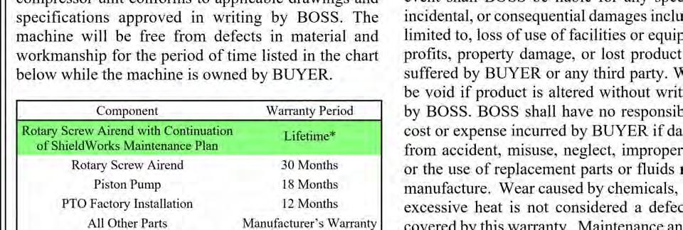
1 P M BA440 PISTON Hydraulic Air Compressor This manual must be read carefully before using your Boss Industries, LLC BA440 PISTON. Store in a safe and convenient location for future reference /20/18 DJH
2
3 Welcome...4 General Information...4 Safety...5 General Safety Overview...5 Safety Precautions...6 Specifications...8 Specification Sheet...8 Installation & Operation...9 Mounting the Compressor...9 Installation of Wiring...10 Connecting the Hydraulic Hoses...10 Connecting the Air Hoses...10 Pre-Start-up Inspection Checks...11 Check All Fluid Levels...11 Machine Documentation...11 Operating Procedure...12 Shutdown Procedure...12 Operating Conditions...12 Maintenance...13 Lifetime Warranty Information...13 Recommended Spare Parts List...13 Maintenance Chart...14 Compressor Oil...15 Compressor Oil Fill, Level, and Drain...16 Changing the Air Intake Filter...16 Changing the Hydraulic Oil Cooler...16 Piston Ring Replacement...16 Oil Pump Replacement...18 Crankshaft and Bearing Replacement...18 Troubleshooting...20 Low Oil Pressure...20 No Oil Pressure...20 Compressor Will Not Engage...20 Compressor Engages But Will Not Pressurize Tank...20 Compressor Does Not Recover Pressure as Fast as it Should...20 Contacting Boss Industries, LLC...20 Warranty...21 Contents


4 General Information Thank you for choosing the Boss Industries, LLC BA440 PISTON Hydraulic Air Compressor. Before operating, carefully read this manual and become well acquainted with your new machine. Doing this will increase your safety and maximize the life of the machine. While this manual is written to be as accurate as possible, Boss Industries, LLC strives to continually improve the efficiency and performance of its machines. As a result, sometimes there may be slight differences between a given version of the manual and the machine. Welcome


5 Safety General Safety Overview


6 Safety Precautions Safety The following safety precautions are a general guide to safe operation of the equipment


7 Safety Precautions (continued) Safety
8 Specifications Specification Sheet Model Type Delivery COMPRESSOR SPECIFICATIONS BA440 PISTON Hydraulic Air Compressor Output Compressor RPM Hyd Flow Hyd Pressure PSI GPM 2100 PSIG PSI GPM 2100 PSIG PSI GPM 2100 PSIG Operating Pressure Range Ambient Operating Temperature Range Oil Capacity (Compressor) Air Service Connection Overall Dimensions Weight PSIG F 1 1/3 quarts 1/2 NPT L X 23 W X H 180 lbs. *CALCULATIONS 85% EFFICIENCY MECHANICAL AND 96% EFFICIENCY VOLUMETRIC. SPECIFICATIONS SUBJECT TO CHANGE WITHOUT PRIOR NOTICE BA440 system is to run intermittently. When the BA440 is installed with other hydraulic drive equipment it will require a dedicated flow line. If other hydraulics are required, the reservoir size should be at least 20 GAL for the BA440 plus all the other manufacturer s requirements. Cooling air intake must not see air temperatures above ambient. Cooling air discharge must have 10 clearance from any obstructions. 20 maximum operating slope

9 Installation & Operation Mounting the Compressor When mounting the compressor, care should be taken to ensure that its location does not impede the operation of other components on the vehicle. For example, if your vehicle is equipped with a crane, you must make sure the compressor will not interfere with the swing of the crane. In addition, the compressor should be installed in an area that permits cool ambient air to enter the air filter and the hot air to exhaust without recirculating into the machine. A minimum of 10 of clearance is needed for the hot discharge air from the cooler. Cool ambient air is drawn in from under the frame. One last consideration in the mounting should be the routing of hydraulic hoses. Be sure these can be safely run to the hydraulic manifold on the machine. The unit should be secured to the vehicle with four 3/8 grade 8 bolts, flat washers, and loc washers. Ensure that you have a sub structure that will support the weight of the compressor. Be sure to follow all National Vehicle Safety Standards

 Pin E (Black) - Battery (Negative Terminal) Connecting the Hydraulic Hoses The hydraulic hoses to the compressor should be connected directly to the hydraulic manifold with")
10 Installation of Wiring This unit is shipped from the factory with all necessary internal wiring installed. The only remaining wiring necessary is the wiring needed to interface your vehicle/power source with the Boss compressor. The unit is shipped with 1 end of a 5 pin connector. They need to be connected as follows: Pin A (Yellow) - 12VDC power supply (24VDC if equipped) Pin B (Red) - Battery (Positive Terminal) Pin C (Green) - PTO Ground Pin D(Orange) - 12VDC output signal (24VDC if equipped) Pin E (Black) - Battery (Negative Terminal) Connecting the Hydraulic Hoses The hydraulic hoses to the compressor should be connected directly to the hydraulic manifold with appropriately sized fittings. The input line should be made from a good quality high pressure (min PSI) hydraulic hose 1/2" or 3/4 i.d. The return line can be made from a medium pressure (min 1000 psi) hydraulic hose 3/4" i.d. Care should be taken to see that the hoses are not installed with kinks or bends that inhibit flow of the hydraulic oil. Lack of flow could result in damage to the motor and compressor. Lastly, check to make sure hoses are not in contact with sharp objects or edges that may fray, chafe, or cut them over time. Secure all hoses with tie down straps or clamps. Installation & Operation Connecting the Air Hoses The air discharge hose should be connected directly to the AIR port. The fitting is a 1/2 female NPT. The air line should be made from a good quality (min 200 Psi) hydraulic hose 1/2 or 3/4 i.d. Care should be taken to see that the hose is not installed with kinks. When adding an air hose, ensure OSHA Regulation is followed
11 Installation & Operation Pre-Start-up Inspection Checks This inspection should be done prior to the compressor test. I. Check all assemblies, clamps, fittings, hose connections, nuts, and bolts to ensure they are properly tied and secured to the vehicle. This is a very critical area of inspection. The vehicle should not be moved until this inspection has been completed. II. Remove all tools, rags, and installation equipment from the area. III. Check all valves to ensure they are in correct operating position. IV. Vacuum all areas that have metal or plastic shavings. Wipe all fingerprints off unit and vehicle. Check All Fluid Levels Position the unit on a level surface so that proper amount of fluids can be added. Machine Documentation Record all serial numbers for this installation. A. Vehicle V.I.N. B. Hydraulic Pump Data C. Compressor Serial Number D. BOSS Serial Number E. Air Tank Serial Number F. Note any special applications relating to specific installations. I. Fuel to provide three hours of operation II. Hydraulic fluid levels may have to be topped off after test. III. Compressor A. Add oil if needed. B. Additional oil may need to be added after test. C. Top off oil level to the FULL line on the dipstick when finished with test. II. Any other applicable fluids III. Transmission fluid and PTO box
12 Operating Procedure Installation & Operation I. Read this manual carefully before proceeding. II. Start power source and allow for warm-up. III. Verify the compressor is disengaged. IV. Engage hydraulic system per company policy. V. Engage compressor Shutdown Procedure I. Disengage compressor circuit. II. Relieve system of stored air. Operating Conditions The following conditions should exist for maximum performance of the compressor: The machine should be as close to level as possible when operating. Ambient temperature for operation should be below 100 F (38 C). The machine may experience high temperature shutdown above this level


13 Maintenance Recommended Spare Parts List PART NUMBER DESCRIPTION Kit, Repair Reed Valve Element, Air Filter Spider, Curved Jaw Q Kit, Repair HYD Motor Seal Lubricant, ShieldWorks 2Q Lifetime Warranty Information In order to maintain the lifetime warranty status on your BA440 PISTON, the required maintenance intervals listed on the following page must be obeyed
 3.")
14 Maintenance Chart Maintenance The MAINTENANCE CHART lists serviceable items on this compressor package. The items are listed according to their frequency of maintenance. INTERVAL REQUIRED MAINTENANCE DAILY 1. Check crankcase oil level. 2. Drain Condensation from air receiver. 1. Inspect the air intake. WEEKLY 2. Check the cylinder head stud torque (See NOTE 2) 3. Check the operation of the receiver safety values. EVERY 3 MONTHS 1. Change the crankcase oil (See NOTE 1) 2. Check cooler fins for dirt and obstructions. Clean if needed. EVERY 6 MONTHS 1. Inspect the drive coupling for wear. 2. Change the air cleaner


15 Maintenance Compressor Oil Recommended Compressor Lubricant: BOSS ShieldWorks 1. Specifications 1. Flash point 496 F minimum. 2. Pour point -40 F. 3. Contains rust and corrosion inhibitors. 4. Contains foam suppressors. 5. Contains oxidation stabilizer. The following are general characteristics for a rotary screw lubricant. Due to the impossibility of establishing limits on all physical and chemical properties of lubricants which can affect their performance in the compressor over a broad range of environmental influences, the responsibility for recommending and consistently furnishing a suitable heavy duty lubricant must rest with the individual supplier if they choose not to use the recommended Boss Industries, LLC ShieldWorks rotary screw lubricant. The lubricant supplier s recommendation must, therefore, be based upon not only the following general characteristics, but also upon his or her own knowledge of the suitability of the recommended lubricant in helical screw type air compressors operating in the particular environment involved


16 Maintenance Compressor Oil Fill, Level, and Drain Before adding or changing compressor oil, make sure that the compressor is completely relieved of pressure. Oil is added at the fill cap on a pipe on the rear of the crankcase. A drain line is located on the rear panel of the machine. Proper oil level is to the FULL line on the dipstick, when the unit is shut down and has had time to settle. The machine must be level when checking the oil. DO NOT OVERFILL. The oil capacity is given in Compressor Specifications. Changing the Hydraulic Oil Cooler The interior of the oil cooler should be cleaned when the pressure drop across it at full flow exceeds 25 PSI. First, remove the cooler. Then, circulate a suitable solvent to dissolve and remove varnish and sludge. Then flush the cooler generously with hydraulic oil. Reinstall the cooler. Once the cooler is reinstalled, fill the hydraulic system with the proper fluid to their appropriate levels. Piston Ring Replacement Shut down the machine and allow to cool for approximately 10 minutes. Next, verify entire system pressure is relieved before proceeding. Then, disconnect air inlet system tubes. Now disconnect 3/4 discharge jumper hose and 3/4 discharge hose. Unscrew the head nuts and remove the heads. Changing the Air Intake Filter The air intake filter is a heavy-duty dry type high efficiency filter designed to protect the compressor from dust and foreign objects. Frequency of maintenance of the filter depends on dust conditions at the operating site. The filter element must be serviced when clogged. A clogged air filter element will reduce compressor performance and cause premature wear of components. Remove the cylinder bolts and tap the sides of the cylinder several times to break it loose from the gasket. Next, rock the cylinder back and forth and lift until it is free. Lift it off of the pistons. To remove the old gasket material, just a single edged razor blade or putty knife
. If the bore is oversized, the cylinder must be replaced. Next, with a ring expander, remove the compression and oil rings.")

17 Maintenance Now hone the cylinder to break the glaze and remove the buildup at the top of the cylinders. Measure the inside diameter of the cylinder for roundness and excessive wear. The bore should be ( tolerance). If the bore is oversized, the cylinder must be replaced. Next, with a ring expander, remove the compression and oil rings. After the old rings have been removed, with the ring expander, install the new ring kit. Make certain that the oil ring is on the bottom and the beveled edge of the compression ring is toward the top of the piston. Now position the cylinder base gasket on the crankcase, using a few drops of oil to hold it in position. Install the cylinder block spacer and gasket on the crankcase. Next you will rotate the rings so that the gaps of the three rings are 120 degrees apart. Lightly lubricate the inside of the cylinder and rotate the crankshaft so that a piston is at the top of the stroke. Compress the rings with a ring compressor and slide the cylinder over the piston. Repeat this step for the other piston. Position the gaskets and valve plate on top of the cylinder. Then position the head on the cylinder and turn bolts finger tight. After tightening with hands, torque the studs/nuts to 240 in-lbs in in-lb increments in the sequence shown below. Now reconnect the 3/4 discharge hose and discharge jumper hose. Next, install the compressor and connect the wiring and test the machine. Now slide the cylinder down until it mates with the crankcase. Start all cylinder mounting bolts until they are snug, then torque the bolts to 180 in-lbs in the sequence shown below. Do not torque the full 180 in-lbs all at once, but in in-lbs increments

18 Maintenance Oil Pump Replacement First, shut down the machine and allow it to cool for at least 10 minutes. Verify that the entire system is pressure relived before proceeding. Next, remove the bolts and lift off the pump cover. Use a single edged razor blade or putty knife to remove the old gasket material, but make sure not to damage the machined surfaces. Crankshaft and Bearing Replacement If it is necessary to replace the crankshaft, related components must also be replaced. Replace both bearings, both races, the key, pump collar, and pump drive pin. Lift the pump out of the cavity and position a new gasket on the rear bearing housing. Next, insert the pump into the cavity and position it slightly to one side using a common screwdriver. Wedge the pump into he piston so that it partially compresses the spring. Note that the driver pin and slot in pump must be in line. Next place the pump cover into position and start two bolts. Strike the pump cover with a rubber mallet to jar the pump loose. When the tension spring can be felt against the pump cover, the pump is lose. Now you can insert the two remaining bolts and torque to 180 in-lbs. The bolts should be torqued in a diagonal pattern. Finally, install the air compressor in the vehicle and connect air lines and wiring. First, shut down the machine and allow it to cool for at least 10 minutes. Verify that the entire system is pressure relived before proceeding. Remove both heads, cylinders, and pistons (See Piston Ring Replacement on pg. 16). Next, remove the bolts on the connecting rods and lift them out. Reassemble the connecting rods to be certain that the matched parts remain together on the same crankshaft journals. Now remove the pump cover, oil pump, sleeve, spring, and rear bearing housing. Next remove the drive hub and the front bearing housing. Next pull the crankshaft from the crankcase and remove all gasket material with a razor blade or putty knife


19 Maintenance Next, press the bearing races out of the bearing housing. Only push the tapered roller bearings off the crankshaft if they re being replaced. If you're replacing the crankshaft, discard the whole assembly. Now press new bearings into the piston and generously oil the front bearing race and install the front bearing housing with gasket. Torque the bolts to 180 in-lbs as shown below. Next install the oil pump and then the connecting rods. Thoroughly oil the crankshaft rods before installing them. When installing the rods, make certain that the tabs are aligned on the same side of the rod as shown below. Finally, install the pistons, rings, and heads (See Piston Ring Replacement on pg. 16) Slide the crankshaft into the crankcase and generously lubricate the bearing race and install rear bearing housing and gaskets

20 Troubleshooting Compressor Engages But Will Not Pressurize Tank If the compressor starts but the tank does not become pressurized, check the following: I. Air leak in plumbing II. Worn piston rings or valve plates Compressor Does Not Recover Pressure as Fast as it Should If the compressor is not recovering pressure at normal speeds, check the following: I. Dirty filter Low Oil Pressure If the oil pressure is too low, check the following: I. Oil level in machine II. Loose pipe plug on oil pump cover II. Air leak in plumbing III. Worn valve plates or piston rings Contacting Boss Industries, LLC III. Worn or defective oil pump IV. Crack or scratch on oil pump cover No Oil Pressure If the oil pressure is nonexistent, check the following: I. Defective oil pump II. Blocked oil passage III. Damaged oil pump drive pin Compressor Will Not Engage If the compressor will not start, check the following: I. No power supplied to compressor II. Internal circuit breaker tripped III. Hydraulic system not engaged IV. Defective pressure switch

21 Warranty
February 26, ch.12.notebook. Ch. 12. Preventative Maintenance and Troubleshooting. Feb 23 5:03 PM
 Ch. 12 Preventative Maintenance and Troubleshooting Feb 23 5:03 PM 1 Why PM? preventive maintenance certain maintenance tasks must be performed regularly to keep an engine working properly helps premature
Routine Compressor Maintenance
 Establishing a regular, well-organized maintenance program and strictly following it is critical to maintaining the performance of a compressed air system. One person should be given the responsibility
Service and Maintenance User Manual
 Service and Maintenance User Manual BOSS BA435 PISTON Hydraulic Air Compressor This manual must be read carefully before using your Boss Industries Air Compressor. Store in a safe and convenient location
Service and Maintenance User Manual
 Service and Maintenance User Manual BOSS K36BP PISTON Hydraulic Air Compressor This manual must be read carefully before using your Boss Industries Air Compressor. Store in a safe and convenient location
A/C COMPRESSOR SERVICING Article Text 1991 Saab 9000 For Copyright 1997 Mitchell International Friday, October 15, :22PM
 Article Text ARTICLE BEGINNING 1991 GENERAL SERVICING Compressor Service * PLEASE READ THIS FIRST * CAUTION: When discharging air conditioning system, use only approved refrigerant recovery/recycling equipment.
This information covers the proper procedure for replacing the Volvo D16F engine in a VT or VNL chassis.
 Volvo Trucks North America Greensboro, NC USA Engine, Replacement DService Bulletin Trucks Date Group No. Page 10.2007 210 139 1(47) Engine, Replacement Volvo D16F VNL, VT W2005773 This information covers
(Replaces Models HD1054)
") DA435EAR: 99900680: 19980521 i Model DA435EAR Underhood Air Compressor (Replaces Models HD1054) IOWA MOLD TOOLING CO., INC. BOX 189, 500 HWY 18 WEST, GARNER, IA 50438 TEL: 515-923-3711 TECHNICAL SUPPORT
DA435EAR: 99900680: 19980521 i Model DA435EAR Underhood Air Compressor (Replaces Models HD1054) IOWA MOLD TOOLING CO., INC. BOX 189, 500 HWY 18 WEST, GARNER, IA 50438 TEL: 515-923-3711 TECHNICAL SUPPORT
GH-BETTIS OPERATING & MAINTENANCE INSTRUCTIONS DISASSEMBLY & ASSEMBLY FOR THE T80X-M4-S DOUBLE ACTING SERIES HYDRAULIC ACTUATORS
 GH-BETTIS OPERATING & MAINTENANCE INSTRUCTIONS DISASSEMBLY & ASSEMBLY FOR THE T80X-M4-S DOUBLE ACTING SERIES HYDRAULIC ACTUATORS -S INDICATES CYLINDERS ARE IN TANDEM PART NUMBER: 100121 REVISION "A" ECN
SPECIFICATIONS TEST AND ADJUSTMENT SPECIFICATIONS SPECIFICATIONS ENGINE FD620D, K SERIES
 ENGINE FD620D, K SERIES SPECIFICATIONS SPECIFICATIONS TEST AND ADJUSTMENT SPECIFICATIONS Engine Oil Pressure Sensor Activates............................... 98 kpa (14.2 psi) Oil Pressure While Cranking
COLT 2310, 2510, AND 2712 COM PACT TRACTORS CHAPTER 9 TROUBLESHOOTING AND ANALYSIS
 COLT 2310, 2510, AND 2712 COM PACT TRACTORS CHAPTER 9 TROUBLESHOOTING AND ANALYSIS 9-A-1 UPON RECEIVING ANENGINE FORRE- PAIR. Learn the history of the unit from the customer. While the customer is present
SYSTEM SAVER 318 AIR COMPRESSOR FOR MACK E-TECH AND ASET ENGINES MAINTENANCE MANUAL
 SYSTEM SAVER 318 AIR COMPRESSOR FOR MACK E-TECH AND ASET ENGINES MAINTENANCE MANUAL NON-THROUGH DRIVE THROUGH DRIVE Service Notes About This Manual This manual provides service and repair procedures for
MODEL DA435HA AIR COMPRESSOR Reference EFFECTIVE SERIAL #:THP
 DA435HA: 99903795: 20060118 MODEL DA435HA AIR COMPRESSOR Reference 20013-002 EFFECTIVE SERIAL #:THP-19934-1005 IOWA MOLD TOOLING BOX 189, 500 HWY 18 WEST, GARNER, IA 50438 TEL: 641-923-3711 TECHNICAL SUPPORT
HYDRAULICS. TX420 & & lower. Hydraulic Tandem Pump Removal. 4. Remove the LH side panel (Fig. 0388).
.") TX420 & 425 240000299 & lower 4. Remove the LH side panel (Fig. 0388). Hydraulic Tandem Pump Removal Note: Cleanliness is a key factor in a successful repair of any hydraulic system. Thoroughly clean all
TX420 & 425 240000299 & lower 4. Remove the LH side panel (Fig. 0388). Hydraulic Tandem Pump Removal Note: Cleanliness is a key factor in a successful repair of any hydraulic system. Thoroughly clean all
Disconnect the APP sensor harness connector. See Fig. 4. Remove the accelerator pedal mounting nuts. Remove the APP assembly.
 ENGINE CONTROLS - REMOVAL, OVERHAUL & INSTALLATION - 6.6L DIESEL... Page 1 of 41 FUEL SYSTEMS ACCELERATOR PEDAL POSITION SENSOR Removal & Installation Disconnect the APP sensor harness connector. See Fig.
Remove Air Cleaner Cover and. Filter
 Remove Air Cleaner Cover and Inspect paper filter for tears Foam pre-cleaner is washable if equipped Replace if necessary Filter Remove Trim Panel Pull throttle lever knob off Remove 3, 8mm screws Remove
SERVICE PARTS LIST SPECIFY CATALOG NO. AND SERIAL NO. WHEN ORDERING PARTS 13 HP DIRECT DRIVE PRESSURE WASHER CATALOG NO
 SPECIFY CATALOG NO. AND SERIAL NO. WHEN ORDERING PARTS HP DIRECT DRIVE PRESSURE WASHER CATALOG NO. 555-22 SERVICE PARTS LIST STARTING SERIAL NUMBER B06A REVISED BULLETIN PAGE OF BULLETIN NO. 5-20-000 DATE
SERVICING INSTRUCTIONS
 TSP Series 66 Triplex Plunger Pump SERVICING INSTRUCTIONS TRIPLEX TRIPLEX SERVICING PUMP PROCEDURES Valve Replacement: All inlet and discharge valves can be serviced without disrupting the inlet or discharge
SERVICE INSTRUCTIONS. Transfer Pump
 TM TM SERVICE INSTRUCTIONS Transfer Pump 6799 DESCRIPTION Model 6799 is an air operated, self-priming, piston type transfer pump designed to transfer gasoline or diesel fuel at 30 gpm or oils up to SAE
ENGINE TUNE-UP INSPECTION OF ENGINE COOLANT INSPECTION OF ENGINE OIL INSPECTION OF BATTERY. INSPECTION OF AIR FILTER (Paper Filter Type)
") ENGINE MECHANICAL - Engine Tune-Up EM-17 ENGINE TUNE-UP INSPECTION OF ENGINE COOLANT (See steps 1 and 2 on page CO-4) INSPECTION OF ENGINE OIL (See steps 1 and 2 on page LU-5) INSPECTION OF BATTERY (See
ENGINE MECHANICAL - Engine Tune-Up EM-17 ENGINE TUNE-UP INSPECTION OF ENGINE COOLANT (See steps 1 and 2 on page CO-4) INSPECTION OF ENGINE OIL (See steps 1 and 2 on page LU-5) INSPECTION OF BATTERY (See
This information covers procedures for replacing the sealant for the crankshaft cover on the Volvo D16F engine.
 Volvo Trucks North America Greensboro, NC USA DService Bulletin Trucks Date Group No. Page 1.2008 216 50 1(17) Sealant Crankshaft Cover, Replacement D16F Sealant Crankshaft Cover, Replacement W2005773
1995 Aerostar/Ranger/Explorer
 Page 1 of 13 Section 03-01C: Engine, 4.0L V-6 DISASSEMBLY AND ASSEMBLY 1995 Aerostar/Ranger/Explorer Workshop Manual Engine Disassembly 1. NOTE: Before starting disassembly, remove all wiring harnesses,
GH-BETTIS SERVICE INSTRUCTIONS DISASSEMBLY & REASSEMBLY FOR MODELS HD521-M4, HD721-M4 AND HD731-M4 DOUBLE ACTING SERIES PNEUMATIC ACTUATORS
 GH-BETTIS SERVICE INSTRUCTIONS DISASSEMBLY & REASSEMBLY FOR MODELS HD521-M4, HD721-M4 AND HD731-M4 DOUBLE ACTING SERIES PNEUMATIC ACTUATORS WITH HYDRAULIC CONTROL PACKAGE PART NUMBER: SE-023 REVISION:
Section 10 Chapter 17
 Section 10 Chapter 17 24 Valve, 8.3 Liter Engine Air Intake System Note: All coding used in the 8.3 Liter and 9 Liter engine manuals are Cummins engine codes. These engine codes have no meaning to New
SPECIFICATIONS TEST AND ADJUSTMENT SPECIFICATIONS SPECIFICATIONS ENGINE FD620D, K SERIES
 TEST AND ADJUSTMENT Engine Oil Pressure Sensor Activates............................... 98 kpa (14.2 psi) Oil Pressure While Cranking (Minimum).......................... 28 kpa (4 psi) Oil Pressure.....................................
Vane Replacement & Complete Rebuild Manual
 National Vacuum Equipment Vane Replacement & Complete Rebuild Manual 607 Challenger Series Rotary Vane Vacuum Pumps MADE IN USA 2013 National Vacuum Equipment, Inc. Revision: 5 (Release) March 2013 No
13. CRANKCASE/CRANKSHAFT/BALANCER/PISTON/CYLINDER
 13. CRANKCASE/CRANKSHAFT/BALANCER/PISTON/CYLINDER COMPONENT LOCATION 13-2 SERVICE INFORMATION 13-3 TROUBLESHOOTING 13-4 CRANKCASE SEPARATION 13-5 CRANKSHAFT 13-7 MAIN JOURNAL BEARING 13-9 CRANKPIN BEARING
Table 6-1. Problems and solutions with pump operations. No Fluid Delivery
 Table 6-1. and solutions with pump operations No Fluid Delivery Fluid level in the reservoir is low. Oil intake pipe or inlet filter is plugged. Air leak in the inlet line prevents priming or causes noise
FOR FUTURE REFERENCE SERIES 93HPS
 Hypro Series 93HPS Hydraulically Driven Wetseal Multistage Pumps Repair Manual KEEP FOR FUTURE REFERENCE Form L-1578R Rev. A SERIES 93HPS Hydraulically Driven Stainless Steel Multistage Centrifugal Pumps
Installation Manual For ISL98, ISL03, ISL07, ISC07
 Installation Manual For ISL98, ISL03, ISL07, ISC07 Table of Contents Section 1: Introduction... 3 Housing Identification... 3 Engine Identification... 3 Special Tools... 3 Automatic Transmissions... 3
12 L * OH**
 Parts Manual Ersatzteil--Liste 12L27.. series 0.9 hp ERGO Short Coupled Low Profile Grinders & Sanders 45--8175 TOOL CLASSIFICATION 12 = ERGO Grinder/Sander 12 L 2 7 12 27 08* OH** -- TYPICAL MODEL THROTTLE
Copper Sleeve, Unit Injector, Replacement
 Volvo Trucks North America Greensboro, NC USA This service bulletin replaces SB 237-46, Copper Sleeve, Unit Injector, Replacement dated 6.2007, publication no. PV776-20177417. DService Bulletin Trucks
CYLINDER HEAD OVERHAUL
 ENGINE OVERHAUL PROCEDURES - GENERAL INFORMATION -2011 Mercedes-... Page 1 of 20 CYLINDER HEAD OVERHAUL * PLEASE READ THIS FIRST * Examples used in this article are general in nature and do not necessarily
Maintenance and Repair
 Maintenance and Repair WARNING ALWAYS shut off the engine, remove key from ignition, make sure the engine is cool, and disconnect the spark plug and positive battery terminal from the battery before cleaning,
Kysor On/Off Rear Air Fan Drive
 . Proper precautions must be taken to prevent personal injury from contact with moving parts, unintended engine start, or other hazards present when working with powered equipment. Refer to the vehicle
Portable Oil Free Silent Series Compressor Operating Instructions
 Portable Oil Free Silent Series Compressor Operating Instructions NOTICE Carefully read this instruction manual before attempting to operate this compressor. MODEL # SERIAL # 1-800-551-2406 www.eaglecompressor.com
Hydraulic Immediate Need Power Pack
 Safety, Operation, and Maintenance Manual WARNING Improper use of this tool can result in serious bodily injury This manual contains important information about product function and safety. Please read
1983 BMW 320i. 1.8L 4-CYL 1983 Engines - 1.8L 4-Cylinder Engines - 1.8L 4-Cylinder
 ENGINE IDENTIFICATION 1.8L 4-CYL 1983 Engines - 1.8L 4-Cylinder For engine repair procedures not covered in this article, see ENGINE OVERHAUL PROCEDURES - GENERAL INFORMATION article in the GENERAL INFORMATION
1.6L 4-CYL - VIN [E]
![1.6L 4-CYL - VIN [E]](/thumbs/81/84172348.jpg "1.6L 4-CYL - VIN [E]") 1.6L 4-CYL - VIN [E] 1993 Nissan Sentra 1993 NISSAN ENGINES 1.6L 4-Cylinder NX, Sentra * PLEASE READ THIS FIRST * NOTE: For engine repair procedures not covered in this article, see ENGINE OVERHAUL PROCEDURES
1.6L 4-CYL - VIN [E] 1993 Nissan Sentra 1993 NISSAN ENGINES 1.6L 4-Cylinder NX, Sentra * PLEASE READ THIS FIRST * NOTE: For engine repair procedures not covered in this article, see ENGINE OVERHAUL PROCEDURES
Installation Instructions
 Preparing your vehicle to install your brake system upgrade 1. Rack the vehicle. 2. If you don t have a rack, then you must take extra safety precautions. 3. Choose a firmly packed and level ground to
FREE $15 Gift Card for every $100 spent on Ship To Home orders. Find Out How
 1 of 29 10/12/2011 5:05 PM FREE $15 Gift Card for every $100 spent on Ship To Home orders. Find Out How Ford Ranger/Explorer/Mountaineer 1991-1999 Intake Manifold REMOVAL & INSTALLATION Print The engines
INSTALLATION INSTRUCTIONS FOR COZY CAB A-1 AIR CONDITIONING KIT
 INSTALLATION INSTRUCTIONS FOR COZY CAB A-1 AIR CONDITIONING KIT 05-11 INSTALLATION INSTRUCTIONS A-12235 Air Conditioner Kit Cab set up instructions; This air conditioning kit is designed to be used with
TC20 Chain Driven Power Take-Off Overhaul Instructions
 TC20 Chain Driven Power Take-Off Overhaul Instructions Table of Contents Section Page Introduction 4 Ordering Repair Parts 4 General Information 5 Special Tools 6 Disassembly See Page 2 Reassembly See
B&M / INTRODUCTION
 INSTALLATION INSTRUCTIONS FOR B&M AUTOMATIC TRANSMISSIONS REPLACING GM TH350, TH400, and TH700R4 / 4L60 (not including 4L60E / electronic shift models) B&M part numbers: 102002-103005 - 107101-107104 107105-107106
This information covers the proper procedure for replacing the intake manifold gasket on the Volvo D16F engine.
 Volvo Trucks North America Greensboro, NC USA DService Bulletin Trucks Date Group No. Page 2.2007 251 39 1(14) Intake Manifold Gasket Replacement D16F Intake Manifold Gasket Replacement W2005773 This information
CAB TILT HYDRAULIC SYSTEM
 OPERATION, MAINTENANCE and SERVICE INSTRUCTIONS CAB TILT HYDRAULIC SYSTEM WITH POWER-PACKER PUMP, CYLINDERS and LATCHES A division of Actuant Corporation 1-800-745-4142 1 www.powerpackerus.com Notice The
20.Cylinder Block. Cylinder Block A: REMOVAL ME(H4DOTC)-63 ST CRANKSHAFT STOPPER
-63 ST CRANKSHAFT STOPPER") Cylinder Block MECHANICAL 20.Cylinder Block A: REMOVAL Before conducting this procedure, drain engine oil completely. 1) Remove the intake manifold. 2)
Cylinder Block MECHANICAL 20.Cylinder Block A: REMOVAL Before conducting this procedure, drain engine oil completely. 1) Remove the intake manifold. 2)
1998 Saab 900 SE ENGINES Saab 2.0L & 2.3L 4-Cylinder
 Removal & Installation See VALVE SPRINGS under CYLINDER HEAD under OVERHAUL. CAMSHAFT Removal 1. Rotate crankshaft until "0" mark on flywheel aligns with timing mark on flywheel cover. Remove inspection
STEERING SYSTEM 6 A POWER STEERING
 STEERING SYSTEM 6 A 22147 POWER STEERING Table of Contents Page Specifications............................ 6A-1 Torque Specification................... 6A-1 Special Tools............................ 6A-1
SD Bendix BX-2150 Air Compressor DESCRIPTION GENERAL DESCRIPTION
 SD-01-331 Bendix BX-2150 Air Compressor WATER OUTLET UNLOADER STOP AIR OUTLET (2) (1 NOT SHOWN) WATER INLET (NOT SHOWN) AIR INLET WATER OUTLET UNLOADER UNLOADER PORTS AIR INTAKE INLET AIR OUTLET DISCHARGE
 Page 1 of 75 303-01D Engine - 5.2L 32V Ti-VCT 2016 Mustang Assembly Procedure revision date: 12/15/2016 Special Tool(s) / General Equipment Engine Base Part Number: 6L084 205-142 (T80T-4000-J) Installer,
BLACKBIRD INSTALLATION SUPPLEMENT
 BLACKBIRD INSTALLATION SUPPLEMENT FOR5.3 AND 6 LITER VORTEC SUBURBAN/YUKON/SILVERADO VERSION 2-06 Blackbird Installation Supplement for GM 5.3 and 6 liter Vortec-Suburban/Silverado Parts Included in Installation
1988 Chevrolet Pickup V SUSPENSION - FRONT (4WD)' 'Front Suspension - "V" Series 1988 SUSPENSION - FRONT (4WD) Front Suspension - "V" Series
' 'Front Suspension - V Series 1988 SUSPENSION - FRONT (4WD) Front Suspension - V Series") 1988 SUSPENSION - FRONT (4WD) Front Suspension - "V" Series DESCRIPTION NOTE: Vehicle serial numbers used in this article has been abbreviated for common reference to Chevrolet and GMC models. Chevrolet
1988 SUSPENSION - FRONT (4WD) Front Suspension - "V" Series DESCRIPTION NOTE: Vehicle serial numbers used in this article has been abbreviated for common reference to Chevrolet and GMC models. Chevrolet
Eclipse GEN 2.0 CAFSystem, Model 150-ECL CAFS PTO Kit Installation Instructions
 Eclipse GEN 2.0 CAFSystem, Model 150-ECL CAFS PTO Kit Installation Instructions Read Read through the the safety installation information instructions overhaul carefully instructions before carefully beginning
Kysor On/Off Rear Air Fan Drive
 . Proper precautions must be taken to prevent personal injury from contact with moving parts, unintended engine start or other hazards present when working with powered equipment. Refer to the vehicle
Water Treatment Plant Maintenance Considerations. Operation and Maintenance. Types of Maintenance 5/1/15
 Water Treatment Plant Maintenance 1 Operation and Maintenance Purpose of O&M maintain design functionality (capacity) restore the system components to their original condition and thus functionality. Effective
DART Aluminum FORD 351 Small Block Technical Notes
 DART Aluminum FORD 351 Small Block Technical Notes Deck Height 9.200 Cleveland 9.500 Windsor Bore 4.00 or 4.125 unfinished Main Bearing Size Cleveland 2.749 Weight. 9.200 91 lb / 9.500 93 lb Maximum bore
EDELBROCK THUNDER SERIES AVS CARBURETORS Part #1801, 1802, 1803, 1804, 1805, 1806, 1812, 1813, 1825, 1826 INSTALLATION INSTRUCTIONS
 EDELBROCK THUNDER SERIES AVS CARBURETORS Part #1801, 1802, 1803, 1804, 1805, 1806, 1812, 1813, 1825, 1826 INSTALLATION INSTRUCTIONS IMPORTANT NOTE: Proper installation is the responsibility of the installer.
RAVEN AIRCRAFT RAVEN INVERTED OIL SYSTEM. Installation Instructions. Why install the Raven Inverted Oil System?
 RAVEN INVERTED OIL SYSTEM RAVEN AIRCRAFT Installation Instructions Why install the Raven Inverted Oil System? Oil pressure is critical to aircraft engine operation and longevity! An aircraft engine draws
Lubrication & Maintenance Schedule
 REMOVE DIRT AND SPILLAGE FROM AROUND THE CRUSHER. REMOVE DUST AND DIRT FROM CRUSHER FRAME SURFACES. REMOVE DUST AND DIRT FROM DRIVE MOTOR. CHECK FLUID LEVELS IN DIESEL ENGINE (IF EQUIPPED). REFER TO ENGINE
SD Bendix DD-3 & SD-3 Safety Actuators PUSH PLATE & SHAFT ASSY. LOCKPORT SERVICE DIAPHRAGM SEPARATOR LOCKING PISTON O-RING LOCKING PISTON
 SD-02-4600 Bendix DD-3 & SD-3 Safety Actuators AUXILIARY DIAPHRAGM SERVICE DIAPHRAGM SEPARATOR PUSH PLATE & SHAFT ASSY. LOCKING PISTON O-RING LOCKING PISTON LOCKPORT DRAIN SLOT RETURN SPRING CAP O-RING
2.2L 4-CYL - VIN [S]
![2.2L 4-CYL - VIN [S]](/thumbs/72/67564355.jpg "2.2L 4-CYL - VIN [S]") 2.2L 4-CYL - VIN [S] 1994 Toyota Celica 1994 ENGINES Toyota 2.2L 4-Cylinder Celica NOTE: For repair procedures not covered in this article, see ENGINE OVERHAUL PROCEDURES - GENERAL INFORMATION article
2.2L 4-CYL - VIN [S] 1994 Toyota Celica 1994 ENGINES Toyota 2.2L 4-Cylinder Celica NOTE: For repair procedures not covered in this article, see ENGINE OVERHAUL PROCEDURES - GENERAL INFORMATION article
Kysor Rear Air Fan Drives
 On/Off Technology for Heavy-Duty Truck Applications Installation & Service Guide Kysor Rear Air Fan Drives thermal.borgwarner.com For Additional BorgWarner Thermal Systems Information: 800-927-7811 USA
REMOVAL & INSTALLATION
 REMOVAL & INSTALLATION NOTE: For reassembly reference, label all electrical connectors, vacuum hoses and fuel lines before removal. Also place mating marks on engine hood and other major assemblies before
OWNER S MANUAL EVOLUTION 3500, 4500, 5500, & 8500 SERIES PUMPS
 OWNER S MANUAL EVOLUTION 3500, 4500, 5500, & 8500 SERIES PUMPS IMPORTANT SAFETY INSTRUCTIONS When installing and using this electrical equipment, basic safety precautions should always be followed, including
Model. Triplex Ceramic Plunger Pump Operating Instructions/ Repair and Service Manual SP100W/SP351W
 Model Triplex Ceramic Plunger Pump Operating Instructions/ Repair and Service Manual SP100W/SP351W Contents: Installation Instructions: page 2 Pump Specifications: pages 3-4 Parts List/Torque Specs.: page
1992 Clutch. Eclipse, Expo/Expo LRV, Galant, Mirage, Precis, 3000GT
 Article Text ARTICLE BEGINNING 1992 Clutch Eclipse, Expo/Expo LRV, Galant, Mirage, Precis, 3000GT DESCRIPTION All clutches are single disc type. Pressure plate assembly uses a diaphragm spring to engage
3.2 DRIVE TORQUE HUB. Roll, Leak and Brake Testing SECTION 3 - CHASSIS & TURNTABLE. 3-2 JLG Lift
 3.2 DRIVE TORQUE HUB Roll, Leak and Brake Testing 10 LUG PATTERN Torque-Hub units should always be roll and leak tested before disassembly and after assembly to make sure that the unit's gears, bearings
2003 Land Rover Freelander S. CAUTION: DO NOT rotate crankshaft or camshafts with timing belt removed and cylinder heads installed.
 FRONT TIMING BELT CAUTION: DO NOT rotate crankshaft or camshafts with timing belt removed and cylinder heads installed. Removal CAUTION: Camshaft timing belt must be replaced if cylinder head is to be
AJV8 Engine Assembly. AJV8 Engine Assembly
 AJV8 Engine Assembly Contents Cylinder Block Dowels, Plugs and Pipes 2 4 Crankshaft Bearing and Cylinder Bore Dimensions 5 9 Bearing Measuring 6 Engine Dimensions and Codes 6 7 Main Bearing Selection Chart
18SP680Rev3 EPA04 MBE 4000 Car Hauler Low Pressure Fuel Lines
 8SP680Rev3 EPA04 MBE 4000 Car Hauler Low Pressure Fuel Lines KIT DESCRIPTION These service kits include all necessary parts to replace the low pressure fuel lines between the fuel filter housing and fuel
2000 Chrysler SEBRING
 2000 Chrysler SEBRING Submodel: JX Engine Type: V6 Liters: 2.5 Fuel Delivery: FI Fuel: GAS 2.0L SOHC and 2.4L DOHC Engines The intake manifold for the 2.0L SOHC engine is a long branch design made of a
Engine. Special Tool(s) Compressor, Piston Ring 303-D032 (D81L-6002-C) or equivalent. Compressor, Valve Spring (T93P-6565-AR)
 Compressor, Piston Ring 303-D032 (D81L-6002-C) or equivalent. Compressor, Valve Spring (T93P-6565-AR)") SECTION 303-01C: Engine 5.4L (4V) 2009 Mustang Workshop Manual ASSEMBLY Procedure revision date: 12/12/2008 Engine Special Tool(s) Compressor, Piston Ring 303-D032 (D81L-6002-C) or equivalent Compressor,
SECTION 303-01C: Engine 5.4L (4V) 2009 Mustang Workshop Manual ASSEMBLY Procedure revision date: 12/12/2008 Engine Special Tool(s) Compressor, Piston Ring 303-D032 (D81L-6002-C) or equivalent Compressor,
3" & 4" Cast Iron Self-Priming Centrifugal Pump Instruction Manual
 12 3" & 4" Cast Iron Self-Priming Centrifugal Pump Instruction Manual 333 & 444 Series Read these instructions and the instructions covering operation of the pump drive unit. Do not operate the gas engine
Purging Air From Divider Block Lubrication Systems
 FROST ENGINEERING SERVICE Purging Air From Lubrication Systems A D I V I S I O N O F G E C S E Y S A L E S & S E R V I C E DESCRIPTION Divider block lubrication systems operate correctly only when all
HOW - TO EMISSION CONTROL BASICS EMISSION CONTROL BASICS
 HOW - TO EMISSION CONTROL BASICS EMISSION CONTROL BASICS Tool And Material Checklist Bore Brush Thermometer Portable Vacuum Pump Screwdriver Combination Wrench Set 3/8 Drive Socket Set Tachometer Rag Service
Engine Compartment Inspection
 Engine Compartment Inspection Unit Contents Student Page Student Components Learning Activities Sheet... 7 3 Abbreviated Checklist.... 7 5 Objective Sheet... 7 7 Expanded Checklist... 7 9 * Job Sheets
Engine Dismantle and Assemble ( )
") Engine Dismantle and Assemble ( 34 8) Special Tools 5 053 Slide hammer 47 Vibration damper remover 47 5053 00 Splined head socket, cylinder head bolts 87 Mounting stand with geared drive 00 059C Installer
Engine Dismantle and Assemble ( 34 8) Special Tools 5 053 Slide hammer 47 Vibration damper remover 47 5053 00 Splined head socket, cylinder head bolts 87 Mounting stand with geared drive 00 059C Installer
ENGINE COOLING SYSTEM
 B ENGINE A SECTION ENGINE COOLING SYSTEM CO C D CONTENTS E PRECAUTIONS... 2 Precautions for Supplemental Restraint System (SRS) AIR BAG and SEAT BELT PRE-TEN- SIONER... 2 Precautions for Liquid Gasket...
MAINTENANCE AND REPAIR INSTRUCTIONS
 MAINTENANCE AND REPAIR INSTRUCTIONS TYPE TH PUMPS Peerless Pump Company Indianapolis IN, 46207-7026 4849357 TABLE OF CONTENTS Maintenance Page 1 & 2 Disassembly Page 5 & 6 Impeller Clearance 3 Reassembly
EXHAUST SYSTEM AND INTAKE MANIFOLD
 J EXHAUST SYSTEM AND INTAKE MANIFOLD 11-1 EXHAUST SYSTEM AND INTAKE MANIFOLD CONTENTS page EXHAUST SYSTEM... 1 EXHAUST SYSTEM DIAGNOSIS... 2 page SERVICE PROCEDURES... 3 TORQUE SPECIFICATIONS... 10 EXHAUST
Type 2 Push-Through 37 Ton Log Splitter. Assembly Manual
 Type 2 Push-Through 37 Ton Log Splitter Assembly Manual Refer to this manual for the following models: RS37PT-LF09PC-16-1 RS37PT-LF09EC-16-1 RS37PT-LF09EC-16-2 RS37PT-LF13EC-22-1 RS37PT-LF13EC-22-2 RS37PT-LF15EC-22-1
Section 10 Chapter 15
 Section 10 Chapter 15 24 Valve, 8.3 Liter Engine Note: All coding used in the 8.3 Liter and 9 Liter engine manuals are Cummins engine codes. These engine codes have no meaning to New Holland warranty codes
DeZURIK " BAW AWWA BUTTERFLY VALVES WITH EPOXY-RETAINED SEAT
 DeZURIK 20 144" BAW AWWA BUTTERFLY VALVES WITH EPOXY-RETAINED SEAT Instruction D10373 April 2017 Instructions These instructions provide information about the 20 (250 F2 model only) and the 24-144 BAW
EDELBROCK THUNDER SERIES AVS CARBURETORS Part #1801, 1802, 1803, 1804, 1805, 1806, 1812, 1813, 1825, 1826 INSTALLATION INSTRUCTIONS
 EDELBROCK THUNDER SERIES AVS CARBURETORS Part #1801, 1802, 1803, 1804, 1805, 1806, 1812, 1813, 1825, 1826 INSTALLATION INSTRUCTIONS PLEASE study these instructions carefully before beginning this installation.
BETTIS SERVICE INSTRUCTIONS DISASSEMBLY AND REASSEMBLY FOR CB-SR-S SEISMIC SPRING RETURN SERIES PNEUMATIC ACTUATORS
 BETTIS SERVICE INSTRUCTIONS DISASSEMBLY AND REASSEMBLY FOR CB-SR-S SEISMIC SPRING RETURN SERIES PNEUMATIC ACTUATORS PART NUMBER: 102264 REVISION: "C" DATE: November 2000 Page 1 of 11 1.0 INTRODUCTION 1.1
ENGINE COOLING SYSTEM
 B ENGINE A SECTION ENGINE COOLING SYSTEM CO C D CONTENTS E PRECAUTIONS... 2 Precautions for Liquid Gasket... 2 REMOVAL OF LIQUID GASKET SEALING... 2 LIQUID GASKET APPLICATION PROCEDURE... 2 PREPARATION...
Torqueflite Manual/Automatic Valve Body
 TCI 122400 Torqueflite Manual/Automatic Valve Body This valve body can be installed in a few hours by carefully following directions. Read all instructions first to familiarize yourself with the parts
Eclipse GEN 2.0 CAFSystem, Model 150-ESECL as used with TC20 Series PTO Installation Instructions
 Eclipse GEN 2.0 CAFSystem, Model 150-ESECL as used with TC20 Series PTO Installation Instructions Read Read through the the safety installation information instructions overhaul carefully instructions
AIR COMPRESSOR OPERATING INSTRUCTION AND PARTS LIST
 AIR COMPRESSOR OPERATING INSTRUCTION AND PARTS LIST BELT TYPE IMPORTANT PLEASE MAKE CERTAIN THAT THE PERSON WHO IS TO USE THIS EQUIPMENT CAREFULLY READS AND UNDERSTANDS THESE INSTRUCTIONS BEFORE STARTING
WARNING Carefully Read These Instructions Before Use
 DO NOT RETURN THIS SPRAYER TO STORE Call: 1-800-950-4458 Backpack Sprayer Use and Care Manual Manufactured for Northern Tool + Equipment Co., Inc. WARNING Carefully Read These Instructions Before Use Model
STEERING HYDRAULICS The steering system is a flow amplified, load sensing, hydraulics arrangement.
 STEERING HYDRAULICS 116821 The steering system is a flow amplified, load sensing, hydraulics arrangement. When the steering wheel is turned, the Steering Metering Pump meters an oil volume proportional
Electric motor testing
 Electric motor testing MOTOR (MODELS EJ4-4001 AND EJ8-4001A) 23 GENERAL INFORMATION The vehicle is equipped with a 48-volt DC, shunt-wound, reversible traction motor. The shunt-wound motor is designed
Geareducer model 2700 and 3000
 USER MANUAL Geareducer model 2700 and 3000 INSTALLATION - OPERATION - MAINTENANCE M02-128C ISSUED 04/2013 READ AND UNDERSTAND THIS MANUAL PRIOR TO OPERATING OR SERVICING THIS PRODUCT. maintenance schedule
Installation Manual. Model T675A Engine Brakes. For Mack 6 Cylinder, 2 valve Head ENDT-673, 675, 676 & E6 Series Engines.
 Engine Brakes Installation Manual Model T675A Engine Brakes For Mack 6 Cylinder, 2 valve Head ENDT-673, 675, 676 & E6 Series Engines TecBrake P.O. Box 27822 Houston, Texas 77227 INSTALLATION MANUAL TECBRAKE
* * APPLICABLE MODELS: 2014 > Mazda 3
 PART NUMBER: 0000 8C L48 (DIO) / 0000 89 L84 (PIO) GENUINE ACCESSORIES INSTALLATION INSTRUCTIONS Rev. AAA *550-0700-000* APPLICABLE MODELS: 2014 > Mazda 3 REQUIRED COMPONENTS: ITEM QTY DESCRIPTION Usage
Industrial Turbo Meters, Sizes 2" through 6"
 Industrial Turbo Meters Sizes 2" through 6" TUR-UM-00530-EN-19 (October 2014) User Manual Industrial Turbo Meters, Sizes 2" through 6" User Manual CONTENTS Scope of the Manual 5 Specifications 5 Product
NUMBER: S.M. REF.: Listed in Table ENGINE: EPA07 Series 60 DATE: October 2012 SUBJECT: REFERENCES TO THE TURBOCHARGER PURGE ROUTINE
 NUMBER: 10 01 12 S.M. REF.: Listed in Table ENGINE: EPA07 Series 60 DATE: October 2012 SUBJECT: REFERENCES TO THE TURBOCHARGER PURGE ROUTINE ADDITIONS, REVISIONS, OR UPDATES Publication Number Platform
Keeping You Cool Under Pressure
 Installation Instruction for 92-93 GM 6.5L Turbo Diesel Series 3500-4 Wheel Drive Pickup and Series 1500, 2500, 3500 4 Wheel Drive Suburban Intercooler System (Part No. 2-436) TOOLS REQUIRED: 1.) Normal
* * APPLICABLE MODELS: 2014 > Mazda 6
 PART NUMBER: 0000 8C H02(DIO) / 0000 89 H18(PIO) GENUINE ACCESSORIES INSTALLATION INSTRUCTIONS Rev. AAA *550-0694-000* APPLICABLE MODELS: 2014 > Mazda 6 REQUIRED COMPONENTS: ITEM QTY DESCRIPTION Usage
Maintenance Instructions
 General Note These instructions contain information common to more than one model of Bevel Gear Drive. To simplify reading, similar models have been grouped as follows: GROUP 1 Models 11, 0, 1,, (illustrated),,