4. FUEL SYSTEM 4-0 FUEL SYSTEM NEXXON 50
|
|
|
- Marvin Parsons
- 5 years ago
- Views:
Transcription
1 4 FUEL SYSTEM SERVICE INFORMATION TROUBLESHOOTING AIR CLEANER REMOVAL THROTTLE VALVE DISASSEMBLY THROTTLE VALVE INSTALLATION CARBURETOR REMOVAL
2 4-1
3 SERVICE INFORMATION GENERAL INSTRUCTIONS Gasoline is very dangerous. When working with gasoline, keep sparks and flames away from the working area. Gasoline is extremely flammable and is explosive under certain conditions. Be sure to work in a well-ventilated area. Do not bend or twist control cables. Damaged control cables will not operate smoothly. When disassembling fuel system parts, note the locations of O-rings. Replace them with new ones during reassembly. Before float chamber disassembly, loosen the drain screw to drain the residual gasoline into a clean container. After the carburetor is removed, plug the intake manifold side with a clean shop towel to prevent foreign matters from entering. The carburetor air jets and fuel jets must be cleaned with compressed air. When the motorcycle is not used for over one month, drain the residual gasoline from the float chamber to avoid erratic idling and clogged slow jet due to deteriorated fuel. SPECIFICATIONS Item Carburetor type Venturi dia. Piston dia Standard PIF φ11 φ13 Main jet 65# Idle speed Throttle grip free play Air screw opening 1700±100rpm 2 6mm 1¾±½ SPECIAL TOOL Float level gauge 4-2
4 TROUBLESHOOTING Engine cranks but won t start No fuel in tank No fuel to carburetor Cylinder flooded with fuel No spark at plug Faulty fuel pump Clogged air cleaner Intake air leak Improper throttle operation Engine idles roughly, stalls or runs poorly Faulty charcoal canister Ignition malfunction Faulty carburetor Poor quality fuel Lean or rich mixture Clogged air cleaner Incorrect idle speed Worn throttle needle Engine lacks power Clogged air cleaner Faulty carburetor Faulty ignition system Lean mixture Clogged carburetor fuel jets Float level too low Intake air leak Faulty charcoal canister Restricted fuel line Rich mixture Float level too low Clogged air jets Clogged air cleaner Misfiring during acceleration Faulty ignition system Faulty carburetor Faulty accelerating pump Faulty charcoal canister Backfiring at deceleration Float level too low Incorrectly adjusted carburetor Faulty exhaust muffler 4-3


5 AIR CLEANER REMOVAL Remove the front cover (page 14-3). Remove the screw attaching the carburetor. Remove the air cleaner case by removing the attaching bolts. Bolt Screw Element Screw. Remove the four screws with the air cleaner case cover. Element Holder Air Cleaner Case Cover Remove the element and the element holder from the air cleaner case. INSTALLATION Install the air cleaner case in the reverse order of removal. 4-4

6 THROTTLE VALVE DIS- ASSEMBLY Remove the front cover (page 14-3). Loosen the carburetor cap and remove the throttle valve. Carburetor Cap Throttle Valve Disconnect the throttle cable from the throttle valve. Throttle Cable Throttle Valve Remove the throttle valve, spring and carburetor top. The carburetor top is an integral part of the throttle cable assembly. The top can not be separated from the assembly without causing damage to the cable. Needle Clip Throttle Valve Remove the jet needle by removing the needle clip. Check the jet needle and throttle valve for wear or damage. Spring Jet Needle 4-5

.")
7 THROTTLE VALVE INSTALLA- TION Set the needle clip on the jet needle clip. Standard podition: 3rd groove from the top Install the jet needle on the throttle valve. Install the retainer on the throttle valve and secure the jet needle. Throttle Cable Throttle Valve Install the throttle cable to the throttle valve while depressing the throttle valve spring. Carburetor Top Throttle Valve Spring Insert the throttle valve into the carburetor, aligning the throttle valve groove with the throttle stop screw. Install the carburetor top onto the carburetor. After installing the carburetor and throttle valve, perform the following adjustments: -Throttle grip free play (page 2-3). -Carburetor air screw adjustment if the carburetor was overhauled or cleaned. Carburetor Top Groove 4-6
.")


8 CARBURETOR REMOVAL Remove the front cover (page 14-3). Loosen the air cleaner connecting tube band. Remove the carburetor top (page 4-6). Carburetor top Choke Cable Remove the fuel tube from the carburetor. Remove the choke cable. Remove the carburetor mounting bolts. Remove the insulator, O-ring and carburetor. Bolts Fuel Tube CARBURETOR DISASSEMBLY Loosen the drain screw to drain the gasoline from the float chamber. Keep sparks and flames away from the work area. Drain gasoline into a clean container. Drain Screw 4-7


9 Float/Float Valve Disassembly Remove the four float chamber attaching screws and remove the float chamber. Screws Remove the float pin, float and float valve. FLOAT/FLOAT VALVE INSPECTION Inspect the float valve seat for wear or damage. Inspect the float for damage or fuel level inside the float chamber. Float MAIN JET/SLOW JETS/AIR SCREW/THROTTLE STOP SCREW REMOVAL Remove the main jet, needle jet holder, and needle jet. Remove the slow jet. Float Valve Seat Needle Jet Holder Float Pin Needle Jet 4-8 Slow Jet Main Jet


10 Remove the air screw and throttle stop screw. CAUTIONS! Be careful not to damage the jets and jet holder when removing them. Before removing, turn the throttle stop screw and air screw in and carefully count the number of turns until they seat lightly and then make a note of this. Do not force the screw against its seat to avoid seat damage. Be sure to install the O-ring in the reverse order of removal. Throttle Stop Screw Air Screw Carburetor Cleaning Blow compressed air through all passages of the carburetor body. Slow Jet/Main Jet Installation Install the slow jet. Install the needle jet, needle jet holder and main jet. Install the throttle stop screw and air screw. When installing the air screw, return it to the original position as noted during removal After the carburetor is installed, be sure to perform the Exhaust Emission Test. Needle Jet Holder Needle Jet Air Screw Install the float valve, float and float pin. Slow Jet Main Jet Throttle Stop Screw Float 4-9 Float Pin


11 FLOAT LEVEL INSPECTION Turn the carburetor upside down so that the float will go down to make the float valve contact the float valve seat. Then slowly tilt the carburetor and measure the float level with the float level gauge while the float pin just contacts with float valve. Float Level: 20mm When adjusting, carefully bend the float pin. Check the float for proper operation and then install the float chamber. Float Level Gauge Choke Cable CARBURETOR INSTALLATION Install the carburetor onto the intake manifold and tighten the two mounting bolts. Install the fuel tube and the choke cable.. Torque: kg-m Install the air cleaner connector and tighten the band screw. Bolt Fuel Tube Assemble the carburetor top and throttle valve spring. Connect the throttle cable to the throttle valve. Carburetor Top 4-10

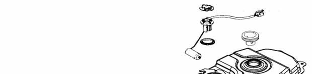
12 FUEL TANK FUEL TANK REMOVAL Warning Keep sparks and flames away from the work area. Wipe off any spilled gasoline. Turn the fuel valve to OFF. Remove the three bolts attaching the rear carrier. Remove the four seat lock nuts. Remove the tool box mounting bolt and tool box. Disconnect the fuel strainer and remove the nuts on the end of the fuel tank. Disconnect the fuel unit wire connector and fuel gauge wire. Remove the fuel tank. Screw Fuel Unit Wire Fuel Strainer FUEL STRAINER REMOVAL Remove the fuel strainer from the fuel tank. INSPECTION Inspect if the fuel strainer is clogged and clean it with compressed air. When removing the fuel strainer, do not allow flames or sparks near the working area and drain the residual gasoline into a container. INSTALLATION Install the fuel strainer with its arrow mark toward the fuel pump. Fuel Unit Wire FUEL TANK INSTALLATION Install the fuel tank in the reverse order of removal. Check that there is no fuel leakage. Check the wire connectors for proper connection. Screw Fuel Strainer 4-11
4. FUEL SYSTEM CK 1 4-0
 4 4 4-0 SERVICE INFORMATION... 4-1 FLOAT LEVEL INSPECTION... 4-5 TROUBLESHOOTING... 4-2 CARBURETOR INSTALLATION... 4-6 THROTTLE VALVE DISASSEMBLY... 4-3 THROTTLE VALVE ASSEMBLY... 4-6 CARBURETOR REMOVAL...
5. FUEL SYSTEM 5-0 FUEL SYSTEM MXU 250R/300R
 5 FUEL SYSTEM 5 SERVICE INFORMATION------------------------------------------------ 5-2 TROUBLESHOOTING----------------------------------------------------- 5-3 FUEL TANK -----------------------------------------------------------------
5. FUEL SYSTEM FUEL SYSTEM 5-0
 5 FUEL SYSTEM 5-0 SERVICE INFORMATION GENERAL INSTRUCTIONS SERVICE INFORMATION...5-1 CARBURETOR INSTALLATION...5-9 TROUBLESHOOTING...5-1 PILOT SCREW ADJUSTMENT...5-10 CARBURETOR REMOVAL...5-2 AUTO BYSTARTER...5-3
5. FUEL SYSTEM 5-0 FUEL SYSTEM UXV 500
 5 FUEL SYSTEM 5 SERVICE INFORMATION------------------------------------------------ 5-02 TROUBLESHOOTING----------------------------------------------------- 5-03 FUEL TANK -----------------------------------------------------------------
12. CARBURETOR 12-0 CARBURETOR VITALITY 50
 12 12 CARBURETOR SERVICE INFORMATION (2-STROKE)... 12-2 SERVICE INFORMATION (4-STROKE)... 12-3 THROTTLE VALVE (2-STROKE)... 12-5 CARBURETOR (2-STROKE)... 12-7 AIR SCREW ADJUSTMENT (2-STROKE)... 12-13 REED
11. CARBURETOR 11-0 CARBURETOR ZX / SCOUT 50
 11 CARBURETOR SERVICE INFORMATION... 11-2 TROUBLESHOOTING... 11-2 THROTTLE VALVE DISASSEMBLY... 11-3 THROTTLE VALVE INSTALLATION... 11-4 CARBURETOR REMOVAL... 11-5 AUTO BYSTARTER... 11-6 FLOAT CHAMBER...
CARBURETOR SERVICE INFORMATION TROUBLESHOOTING THROTTLE VALVE DISASSEMBLY THROTTLE VALVE INSTALLATION...
 11 CARBURETOR SERVICE INFORMATION... 11-2 TROUBLESHOOTING... 11-2 THROTTLE VALVE DISASSEMBLY... 11-3 THROTTLE VALVE INSTALLATION... 11-4 CARBURETOR REMOVAL... 11-5 AUTO BYSTARTER... 11-6 FLOAT CHAMBER...
12. CARBURETOR/FUEL PUMP
 12 CARBURETOR/FUEL PUMP SERVICE INFORMATION... 12-2 TROUBLESHOOTING... 12-2 THROTTLE VALVE DISASSEMBLY... 12-3 THROTTLE VALVE INSTALLATION... 12-4 CARBURETOR REMOVAL... 12-5 AUTO BYSTARTER... 12-6 FLOAT
7. FUEL SYSTEM ('04 - '05)
") 7. FUEL SYSTEM ('04 - '05) SYSTEM COMPONENTS 7-2 CARBURETOR DISASSEMBLY 7-81 SERVICE INFORMATION 7-3 CARBURETOR ASSEMBLY 7-14 TROUBLESHOOTING 7-4 CARBURETOR INSTALLATION 7-21 AIR CLEANER HOUSING 7-5 PILOT
7. FUEL SYSTEM ('04 - '05) SYSTEM COMPONENTS 7-2 CARBURETOR DISASSEMBLY 7-81 SERVICE INFORMATION 7-3 CARBURETOR ASSEMBLY 7-14 TROUBLESHOOTING 7-4 CARBURETOR INSTALLATION 7-21 AIR CLEANER HOUSING 7-5 PILOT
13. FUEL SYSTEM/CARBURETOR/
 13 FUEL SYSTEM/CARBURETOR/FUEL PUMP FUEL SYSTEM --------------------------------------------------------- 13-1 SCHEMATIC DRAWING ---------------------------------------------- 13-2 OPERATION OF CARBURETOR
FUEL SYSTEM/CARBURETOR/FUEL PUMP
 13 FUEL SYSTEM/CARBURETOR/FUEL PUMP FUEL SYSTEM-------------------------------------------------------------------------------------13-1 SCHEMATIC DRAWING-------------------------------------------------------------------------13-2
Do not bend or twist the control cable. Damaged control cable will not operate smoothly and may stick or bind.
 XL200 4. FUEL SYSTEM SERVICE INFORMATION 4-1 TROUBLESHOOTING 4-2 CARBURETOR 4-3 PILOT SCREW ADJUSTMENT 4-14 ACCELERATOR PUMP ADJUSTMENT 4-15 AIR CLEANER HOUSING 4-15 FUEL TANK 4-16 SERVICE INFORMATION
~. a~' ~ ( I o~~~ 4-0. ~Sj~' AO~ i/~ CB1000C (ij)aon'da in-ib) ~ "" ~ ~!~~P. ~ J N m (6-12 kg-em,
aon'da in-ib) ~ ~ ~!~~P. ~ J N m (6-12 kg-em,") e V ~. a~' ~ I ~ J C t \"" 8.0- ( I o~~~ ~ "" ~ ~. ~!~~P. C8 0 & 0,-t. ~ CB1000C (ij)aon'da 0.6-1.2 N m (6-12 kg-em, 5-10 in-ib) 4-0 / 4.0-6.0 N m (40-60 kg-em, 35-52 in-i b) t$ "'07~ / c;:::/ j ~Sj~'
e V ~. a~' ~ I ~ J C t \"" 8.0- ( I o~~~ ~ "" ~ ~. ~!~~P. C8 0 & 0,-t. ~ CB1000C (ij)aon'da 0.6-1.2 N m (6-12 kg-em, 5-10 in-ib) 4-0 / 4.0-6.0 N m (40-60 kg-em, 35-52 in-i b) t$ "'07~ / c;:::/ j ~Sj~'
FUEL SYSTEM CIRCUIT D'ESSENCE KRAFTSTOFFSYSTEM
 CIRCUIT D'ESSENCE KRAFTSTOFFSYSTEM 41 FUEL SYSTEM SERVICE INFORMATION TROUBLESHOOTING FUEL TANK AIR CLEANER CARBURETOR REMOVAL VACUUM CHAMBER FLOAT CHAMBER 4-1 PILOT SCREW 4-2 CARBURETOR SEPARATION 4-3
6. FUEL SYSTEM 6-1 FUEL TANK COMPONENT LOCATION 6-2 INTAKE PIPE SERVICE INFORMATION 6-3 CARBURETOR TROUBLESHOOTlNG 6-4
 6... COMPONENT LOCATION 6-2 SERVICE INFORMATION 6-3 TROUBLESHOOTlNG 6-4 AIR CLEANER HOUSING 6-5 FUEL TANK...... 6-5 INTAKE PIPE...... 6-6 CARBURETOR.............. 6-6 AIR SCREW ADJUSTMENT 6-15 6-1 COMPONENT
Engine Does Not Start or Is Hard to Start Cause of Trouble. 1. Open the drain screw, and check Fuel not supplied (1) Fuel tank empty
 Fuel tank empty") 20. Engine Does Not Start or Is Hard to Start 20-1 Engine Output Insufficient 20-2 Poor Performance at Low Speed and Idling 20-3 Poor Performance at High Speed 20-3 Unsatisfactory Operation 20-4 Fuel Gauge
20. Engine Does Not Start or Is Hard to Start 20-1 Engine Output Insufficient 20-2 Poor Performance at Low Speed and Idling 20-3 Poor Performance at High Speed 20-3 Unsatisfactory Operation 20-4 Fuel Gauge
1. GENERAL INFORMATION
 GENERAL INFORMATION ENGINE SERIAL NUMBER ---------------------------------------------- - SPECIFICATIONS ---------------------------------------------------------- - 2 SERVICE PRECAUTIONS ------------------------------------------------
WEBER CARBURETOR TROUBLESHOOTING GUIDE
 This guide is to help pinpoint problems by diagnosing engine symptoms associated with specific vehicle operating conditions. The chart will guide you step by step to help correct these problems. For successful
FUEL SYSTEM. Table of Contents. Specifications. Section 3A Fuel Delivery System. Models 6/8/9.9/10/15 CARBURETOR SPECIFICATIONS
 FUEL SYSTEM Section 3A Fuel Delivery System Table of Contents Specifications............................. 3A-1 WMC Carburetor Specifications............. 3A-2 WMC Carburetor Specifications.............
20. TROUBLESHOOTING ENGINE DOES NOT START OR IS HARD TO START XL200
 20. ENGINE DOES NOT START OR IS HARD TO START 20-1 ENGINE LACKS POWER 20-2 POOR PERFORMANCE AT LOW AND IDLE SPEED 20-3 POOR PERFORMANCE AT HIGH SPEED 20-4 POOR HANDLING 20-4 ENGINE DOES NOT START OR IS
FU-1 FUEL SYSTEM. Page PRECAUTIONS... TROUBLESHOOTING... ON-VEHICLE INSPECTION...
 FU-1 FUEL SYSTEM PRECAUTIONS... TROUBLESHOOTING... ON-VEHICLE INSPECTION... CARBURETOR FUEL PUMP... Page FU-2 FU-2 FU-3 FU-4 FU-28 FU-2 FUEL SYSTEM - Precautions, Troubleshooting PRECAUTIONS 1. Before
1. GENERAL INFORMATION
 1. GENERAL INFORMATION 1 1 GENERAL INFORMATION ENGINE FRAME VIN SERIAL NUMBER... 1-2 SPECIFICATIONS (125 CC)... 1-3 SPECIFICATIONS (150 CC)... 1-4 SERVICE PRECAUTIONS... 1-5 TORQUE VALUES... 1-7 TOOLS...
CARBURETOR - HITACHI 2-BBL
 CARBURETOR - HITACHI 2-BBL 1986 Isuzu Trooper II 1986 Hitachi Carburetors HITACHI DCH340, DCR384, DFP340, DFP384 & DHP340 2-BARREL P UP & Trooper II DESCRIPTION Carburetor is a 2-barrel downdraft type
SECTION 4 - FUEL/LUBRICATION/COOLING
 For Arctic Cat Discount Parts Call 606-678-9623 or 606-561-4983 SECTION 4 - FUEL/LUBRICATION/COOLING 4 TABLE OF CONTENTS Carburetor Specifications... 4-2 Carburetor Schematic... 4-2 Carburetor... 4-3 Cleaning
Typical Install Instructions
 Typical Install Instructions Read & understand all steps of these instructions before beginning this installation. WEBER Conversion Kit, VW T-1/2, up to 1835cc 32 / 36 DFEV Weber Carburetor These instructions
SPECIFICATIONS ITEM TORQUE NOTES. Air cleaner backplate screw 7-9 ft-lbs Nm LOCTITE THREADLOCKER 242 (blue), page 4-19
, page 4-19") 4 SPECIFICATIONS CARBURETOR JET SIZES CARBURETOR ADJUSTMENTS Main jet 195 Slow jet 42 FUEL TANK CAPACITY GALLONS LITERS Total (including reserve) 4.0 15.14 Reserve 0.6 2.27 Engine fast idle speed (using
4 SPECIFICATIONS CARBURETOR JET SIZES CARBURETOR ADJUSTMENTS Main jet 195 Slow jet 42 FUEL TANK CAPACITY GALLONS LITERS Total (including reserve) 4.0 15.14 Reserve 0.6 2.27 Engine fast idle speed (using
PIERBURG. Carburetor: 2E3
 PIERBURG Carburetor: 2E3 1 fast idle adjusting screw 2 throttle lever 3 fuel mixture adjusting screw 4 main body 5 idle cut off valve 6 stop screw 7 accelerator pump cover 8 diaphragm 9 spring 10 valve
FUEL AND LUBRICATION SYSTEM
 AND LUBRICATION SYSTEM 4-1 A-PDF Split DEMO : Purchase from www.a-pdf.com to remove the watermark AND LUBRICATION SYSTEM CONTENTS SYSTEM... 4-2 PUMP... 4-2 TANK/ COCK... 4-3 REMOVAL... 4-3 INSPECTION...
CARBURETOR ROUND SLIDE 2 STROKE ENGINES
 ROUND SLIDE STROKE ENGINES The motorcycle carburetor is a very touchy device that can cause all kinds of trouble if mishandled or neglected. Our experience indicates that most of the carburetors sent under
SPECIFICATIONS 4.1 ITEM TORQUE NOTES. Air Cleaner Cover Screws in-lbs Nm LOCTITE THREADLOCKER 222 (purple), page 4-21
, page 4-21") 4 SPECIFICATIONS 4.1 CARBURETOR JET SIZES CARBURETOR ADJUSTMENTS Main Jet 195 Slow Jet 42 FUEL TANK CAPACITY GALLONS LITERS Total (including reserve) 5.0 18.93 Reserve 0.6 2.2 Engine Fast Idle Speed (using
4 SPECIFICATIONS 4.1 CARBURETOR JET SIZES CARBURETOR ADJUSTMENTS Main Jet 195 Slow Jet 42 FUEL TANK CAPACITY GALLONS LITERS Total (including reserve) 5.0 18.93 Reserve 0.6 2.2 Engine Fast Idle Speed (using
Fuel Injection System
 7. Fuel Injection System XCITING 400i Fuel Injection System This chapter covers the location and servicing of the fuel system components for the KYMCO XCITING 400i. Air box... 7-2~7-5 Fuel Tank... 7-6~7-10
SECTION 4 - FUEL SYSTEMS AND CARBURETION
 SECTION - FUEL SYSTEMS AND CARBURETION FUEL SYSTEMS - - - - - - - - - - - - - - - - - - - - - - - - - - - - - - - - - - - - - - - - - - - - - - - - - - - - - - - - - - - - - -62 FUEL PUMP - - - - - - -
Service Instruction ENGINE COMPONENTS, INC.
 Title: Service Instruction S.I. No.: 89-5-1 Page: 1 of 5 Issued: 05/05/89 Revision: 1 (09/01/01) Technical Portions of FAA DER Approved. FAILURE OF ENGINE TO START 27 points 1. Lack of fuel 2. Ignition
MIKUNI VM26 Carburetor Kit Instruction Manual
 MIKUNI VM26 Carburetor Kit Instruction Manual (For exclusive use in the Super Head 4VALVE+R-equipped motorcycle) Item No. (Carburetor set) AKEGAWA-made products. Please strictly follow the following instructions
AN EXPLANATION OF CIRCUITS CARTER YH HORIZONTAL CLIMATIC CONTROL CARBURETER
 AN EXPLANATION OF CIRCUITS CARTER YH HORIZONTAL CLIMATIC CONTROL CARBURETER The Carter Model YH carbureter may be compared with a Carter YF downdraft carbureter with the circuits rearranged to operate
CARBURETOR. Preliminary Check. Removal of DuraForce Carburetor
 Fuel Leaks From Carburetor (Leaking starts after running, stops after shutdown) Note: This condition which does NOT drain the fuel tank is called spit-back. Possible Causes Engine RPM out of proper range
HSR Carburetor Easy Kits Installation Instructions For Evo Big Twin Kit: # 42-7 Twin Cam Kit: # 42-18
 HSR Carburetor Easy Kits Installation Instructions For Evo Big Twin Kit: # 42-7 Twin Cam Kit: # 42-18 Revised 5/01/01 EK-1 Easy Kit Installation Instructions The HSR series carburetors are precise yet
HER CHEE INDUSTRIAL CO., LTD.
 SERVICE MANUAL ATV-320 S/U 2002/24 JUNE 30, 2007 High Power Liquid Cooled Engine HER CHEE INDUSTRIAL CO., LTD. Foreword This service manual contains information on servicing ATV-320(S/U) This manual is
CHAPTER 4 FUEL SYSTEM
 CHAPTR 4 FUL SYSTM FUL SYSTM... 4-1 XPLODD DIAGRAM... 4-1 FUL LIN... 4-2 RMOVAL... 4-3 CLANING AND INSPCTION... 4-3 FUL TANK... 4-3 FUL MTR COMPLT... 4-4 PRIMING PUMP... 4-4 FUL FILTR... 4-4 FUL JOINTS...
TILLOTSON LTD., CLASH INDUSTRIAL ESTATE, TRALEE, CO. KERRY, IRELAND PHONE: FAX:
 TILLOTSON LTD., CLASH INDUSTRIAL ESTATE, TRALEE, CO. KERRY, IRELAND PHONE: +353 66 7121911 FAX: +353 66 7124503 e-mail: sales@tillotson.ie HS SERIES SERVICE MANUAL INTRODUCTION The demand for a miniature
TILLOTSON LTD., CLASH INDUSTRIAL ESTATE, TRALEE, CO. KERRY, IRELAND PHONE: FAX:
 TILLOTSON LTD., CLASH INDUSTRIAL ESTATE, TRALEE, CO. KERRY, IRELAND PHONE: +353 66 7121911 FAX: +353 66 7124503 e-mail: sales@tillotson.ie HU SERIES SERVICE MANUAL INTRODUCTION To keep apace of new market
1. GENERAL INFORMATION
 ENGINE SERIAL NUMBER...- SPECIFICATIONS...- 2 SERVICE PRECAUTIONS...- 3 TORQUE VALUES...- TOOLS...-2 LUBRICATION POINTS...-3 CABLE & HARNESS ROUTING...-5 WIRING DIAGRAM...-20 TROUBLESHOOTING...-2 ENGINE
CARTER DOWNDRAFT CARBURETOR Terraplane All Models. Technical Information
 CARTER DOWNDRAFT CARBURETOR 1934 Terraplane All Models Technical Information . Carter W-1 Downdraft Carburetors 1934 Terraplane Challenger, Model KS NOTE: Terraplane Models. Carburetor fitted with Anti-
Tillotson Tc3A Carburator
 Tillotson Tc3A Carburator 176 FUEL SYSTEMS - 5B-11 CENTER BOWL TYPE CARBURETOR Removal 1. Remove front cowl cover and wrap-around cowl. 2. Remove swivel link from lower carburetor. (Figure 2) 3. Loosen
6. FUEL SYSTEM 6-1 SYSTEM COMPONENTS 6-2 CARBURETOR 6-5 SERVICE INFORMATION 6-2 CARBURETOR HEATER (EXCEPT CO, III LA TYPES) 6-10 TROUBLESHOOTING 6-3
 6-10 TROUBLESHOOTING 6-3") dummytext 6. FUEL SYSTEM 6 SYSTEM COMPONENTS 6-2 SERVICE INFORMATION 6-2 TROUBLESHOOTING 6-3 AIR CLEANER HOUSING 6-4 CARBURETOR 6-5 CARBURETOR HEATER (EXCEPT CO, III LA TYPES) 6-10 PILOT SCREW ADJUSTMENT
dummytext 6. FUEL SYSTEM 6 SYSTEM COMPONENTS 6-2 SERVICE INFORMATION 6-2 TROUBLESHOOTING 6-3 AIR CLEANER HOUSING 6-4 CARBURETOR 6-5 CARBURETOR HEATER (EXCEPT CO, III LA TYPES) 6-10 PILOT SCREW ADJUSTMENT
KING CANADA 950W PORTABLE GENERATOR MODEL: KCG-951G INSTRUCTION MANUAL COPYRIGHT 2011 ALL RIGHTS RESERVED BY KING CANADA TOOLS INC.
 KING CANADA 950W PORTABLE GENERATOR MODEL: KCG-951G INSTRUCTION MANUAL COPYRIGHT 2011 ALL RIGHTS RESERVED BY KING CANADA TOOLS INC. WARRANTY & SERVICE INFORMATION 1-YEAR LIMITED WARRANTY FOR THIS 950W
TILLOTSON LTD., CLASH INDUSTRIAL ESTATE, TRALEE, CO. KERRY, IRELAND PHONE: FAX:
 TILLOTSON LTD., CLASH INDUSTRIAL ESTATE, TRALEE, CO. KERRY, IRELAND PHONE: +353 66 7121911 FAX: +353 66 7124503 e-mail: sales@tillotson.ie SERIES SERVICE MANUAL INTRODUCTION The gasoline engine industry
TECH INFORMATION EMPI D Performance 2-Barrel Carburetor
 TECH INFORMATION EMPI D Performance 2-Barrel Carburetor The New EMPI D 2-Barrel Performance Carburetor.Built specifically for the VW Aftermarket. With all the features that you have asked for More Progression
Engine Removal/Installation
 Engine Removal/Installation Make sure jacks and safety stands are placed properly and hoist brackets are attached to correct positions on the engine. (See Section 1). Apply parking brake and block rear
CHAPTER 4. CARBURETION
 CHAPTER 4. CARBURETION CARBURETOR... 4l SECTIONAL VIEW.... 42 REMOVAL... 44 DISASSEMBLY... 44 INSPECTION... 47 ASSEMBLY... 48 INSTALLATION....4l 1 ADJUSTMENT....4l 1 1 C A R B U R E T O R CARBURETOR @connection
3. INSPECTION/ADJUSTMENT
 SERVICE INFORMATION...3-0 FINAL REDUCTION GEAR OIL...3-7 MAINTENANCE SCHEDULE...3-2 DRIVE BELT...3-7 FUEL FILTER...3-3 BRAKE SHOE...3-8 THROTTLE OPERATION...3-3 BRAKE ADJUSTING NUT...3-8 AIR CLEANER...3-4
CH. 48 ENGINE MECHANICAL PROBLEMS TEST
 TERRY FOX AUTOMOTIVE CH. 48 ENGINE MECHANICAL PROBLEMS TEST WHEN YOU ARE DONE THIS TEST GUESS WHAT YOU THINK YOU WILL RECEIVE FOR A MARK BELOW. IF YOU ARE WITHIN 2 MARKS YOU WILL RECEIVE 2 BONUS MARKS.
Carburetor Instructions
 Carburetor Instructions for HUDSON SUPER SIX ESSEX SIX CYLINDER Hudson Motor Car Co. DETROIT, U.S.A. Carburetor The carburetor is a device for metering correct amounts of fuel and air for the various
HSR Carburetor. Total Kits. Installation Instructions. # Evo Big Twin # present Twin Cam
 HSR Carburetor Total Kits Installation Instructions HSR42 Kits: HSR45 Kits: #42-8 84-99 Evo Big Twin #42-19 99 - present Twin Cam #45-2 84-99 Evo Big Twin #45-3 84-99 Evo Big Twin #45-4 99 - present Twin
WORKSHOP MANUAL. 63,4 cm³ chainsaws
 WORKSHOP MANUAL General failures analysis Suggested tools I. Emak tool kit II. Compression tester: to check thermal group III. Electronic tachometer: for 2 and 4 stroke engines, measurement range from
COLT 2310, 2510, AND 2712 COM PACT TRACTORS CHAPTER 9 TROUBLESHOOTING AND ANALYSIS
 COLT 2310, 2510, AND 2712 COM PACT TRACTORS CHAPTER 9 TROUBLESHOOTING AND ANALYSIS 9-A-1 UPON RECEIVING ANENGINE FORRE- PAIR. Learn the history of the unit from the customer. While the customer is present
MODELS 3100,3130,3160, 1300, 1330,1360 EXHAUST SYSTEM
 MODELS 3100,3130,3160, 1300, 1330,1360 EXHAUST SYSTEM WALBRO CARBURETOR "WA" SERIES MUFFLER REMOVAL CARBURETOR REMOVAL The muffler assembly should beremoved periodically to inspect for excessive carbon
Body type location. Model number location. Small Engine Parts
 Body type location Model number location Small Engine Parts FUEL PUMP SYSTEM SYSTEMS AND OPERATION The fuel pump on a diaphragm carburetor uses the vacuum and pressure pulse from the engines crankcase
Oregon Fuel Injection
 Cummins PT Fuel Pump Diagnostic No Start, with no smoke 1. This could be caused by the fuel pump not turning or a seized gear pump. Remove the fuel supply hose and the fuel inlet fitting from the gear
ENG CRANKCASE AND REED VALVE. REED VALVE INSPECTION 1. Measure: 8 Valve stopper height 1 Out of specification Adjust stopper/replace valve stopper.
 CRANKCASE AND REED VALVE ENG REED VALVE INSPECTION. Measure: 8 Valve stopper height Out of specification Adjust stopper/replace valve stopper. Valve stopper height 6.0~6. mm(0.~0.5 in). Measure: 8 Reed
BR-250 / BR-250SS / M2-250 SERVICE MANUAL
 BR-250 / BR-250SS / M2-250 SERVICE MANUAL Manufactured by PGO of Motive Power Industry Co., Ltd 1. INSPECTION/ADJUSTMENT 1 1 INSPECTION/ADJUSTMENT SERVICE INFORMATION -------------------------------------------------
3. INSPECTION/ADJUSTMENT
 3 SERVICE INFORMATION...3-0 FINAL REDUCTION GEAR OIL...3-7 MAINTENANCE SCHEDULE...3-2 DRIVE BELT...3-7 FUEL FILTER...3-3 BRAKE SHOE...3-8 THROTTLE OPERATION...3-3 BRAKE ADJUSTING NUT...3-8 AIR CLEANER...3-4
Instruction Model 18537
 Instruction 738-556 Model 18537 LIMITED WARRANTY H. D. Hudson Manufacturing Company warrants to the original purchaser only that this product will continue to function as intended if used in accordance
General Service Information
 KYMCO MXU 500i/700i Repair Manual Fuel System MXU 700i 3.Fuel System MXU 700i This chapter covers the location and servicing of the fuel system components for the fuel injected KYMCO MXU 700i models. 1.Airbox...
TURBOCHARGER Toyota Celica DESCRIPTION OPERATION TURBOCHARGING SYSTEMS All Models
 TURBOCHARGER 1988 Toyota Celica 1988 TURBOCHARGING SYSTEMS All Models DESCRIPTION Most models use a water-cooled turbocharger, mounted directly to the exhaust manifold with a wastegate assembly attached
INSTRUCTION SHEET Rochester Carburetor Models 4G 4GC
 INSTRUCTION SHEET Rochester Carburetor Models 4G 4GC General Exploded View The general design and parts shown will vary to individual units covered on this instruction sheet. Disassembly Use the exploded
Section 5 Fuel System and Governor
 Section Description The Command horizontal twins use three different types of fuel systems; carbureted, electronic fuel injection (EFI), or gaseous. Gaseous fuel systems can be either liquefied petroleum
A-PDF Split DEMO : Purchase from to remove the watermark
 5-18 FUEL AND LUBRICATION SYSTEM A-PDF Split DEMO : Purchase from www.a-pdf.com to remove the watermark Use a % size drill bit with a drill-stop to remove the pilot screw plug. Set the drill-stop 6 mm
A. Perform a vacuum gauge test to determine engine condition and performance.
 ENGINE REPAIR UNIT 2: ENGINE DIAGNOSIS, REMOVAL, AND INSTALLATION LESSON 2: ENGINE DIAGNOSTIC TESTS NOTE: Testing the engine s mechanical condition is required when the cause of a problem is not located
7649A FUEL INJECTOR CLEANING SPECIALTY TOOLS USER MANUAL & REPLACEMENT PARTS LIST
 7649A FUEL INJECTOR CLEANING SPECIALTY TOOLS USER MANUAL & REPLACEMENT PARTS LIST Safety Precautions WARNING: The following safety precautions must be carefully observed to reduce the risk of fire and
EDELBROCK PERFORMER SERIES EMISSIONS LEGAL CARBURETOR 600cfm, Electric Choke, EGR, Square-Bore Carburetor. Part #1400 INSTALLATION INSTRUCTIONS
 EDELBROCK PERFORMER SERIES EMISSIONS LEGAL CARBURETOR 600cfm, Electric Choke, EGR, Square-Bore Carburetor INSTALLATION INSTRUCTIONS PLEASE study these instructions carefully before beginning this installation.
EDELBROCK THUNDER SERIES AVS CARBURETORS Part #1801, 1802, 1803, 1804, 1805, 1806, 1812, 1813, 1825, 1826 INSTALLATION INSTRUCTIONS
 EDELBROCK THUNDER SERIES AVS CARBURETORS Part #1801, 1802, 1803, 1804, 1805, 1806, 1812, 1813, 1825, 1826 INSTALLATION INSTRUCTIONS IMPORTANT NOTE: Proper installation is the responsibility of the installer.
7. CYLINDER HEAD/VALVES
 7 7 7-0 SERVICE INFORMATION...7-1 CYLINDER HEAD DISASSEMBLY...7-7 TROUBLESHOOTING...7-2 CYLINDER HEAD ASSEMBLY...7-8 CAMSHAFT REMOVAL...7-3 CYLINDER HEAD INSTALLATION...7-8 CYLINDER HEAD REMOVAL...7-5
JOB AID INTRODUCTION TOOLS REQUIRED: GC160 GC190 GS190 GCV160 GCV190 GSV160 GSV190 CARBURETOR CLEANING
 JOB AID GC160 GC190 GS190 GCV160 GCV190 GSV160 GSV190 CARBURETOR CLEANING INTRODUCTION Service engineering has discovered that many GCV carburetors returned for warranty were improperly cleaned. Eighty
3. INSPECTION/ADJUSTMENT
 3 3 INSPECTION/ADJUSTMENT SERVICE INFORMATION -------------------------------------------- 3-1 MAINTENANCE SCHEDULE ---------------------------------------- 3-2 FUEL LINE/FUEL FILTER -------------------------------------------
HSR Carburetor. Total Kits. Installation Instructions. # Evo Big Twin # present Twin Cam
 HSR Carburetor Total Kits Installation Instructions HSR42 Kits: HSR45 Kits: #42-8 84-99 Evo Big Twin #42-19 99 - present Twin Cam #45-2 84-99 Evo Big Twin #45-3 84-99 Evo Big Twin #45-4 99 - present Twin
Fuel System Diagnosis
 1996 Chevrolet Impala Caprice, Impala, Roadmaster (VIN B) Service Manual Engine Engine Controls - 4.3L (Caprice Only) and 5.7L Diagnostic Information and Procedures Document ID: 37723 Fuel System Diagnosis
TILLOTSON LTD., CLASH INDUSTRIAL ESTATE, TRALEE, CO. KERRY, IRELAND PHONE: FAX:
 TILLOTSON LTD., CLASH INDUSTRIAL ESTATE, TRALEE, CO. KERRY, IRELAND PHONE: +353 66 7121911 FAX: +353 66 7124503 e-mail: sales@tillotson.ie HR SERIES SERVICE MANUAL INTRODUCTION Tillotson has developed
TROUBLESHOOTING FLOW CHARTS
 TROUBLESHOOTING FLOW CHARTS Bowl Style Carburetor Troubleshooting Hunts and Surges Will Run only on Prime Will run only if the choke is used Determine that the governor system is functioning properly
Fuel System Diagnosis
 Page 1 of 8 Document ID# 104786 1997 Chevrolet Corvette Feedback Print Fuel Diagnosis (1) Fuel Pressure Gauge Bleed Hose (2) J 37287 Fuel Line Shut-off Adapters (3) Return Pipe (4) Feed
FUEL SYSTEM SECTION FL CONTENTS B ENGINE FL-1
 FUEL SYSTEM B ENGINE SECTION FL A FUEL SYSTEM FL C D CONTENTS E PRECAUTIONS... 2 Precautions for Battery Service... 2 PREPARATION... 3 Commercial Service Tools... 3 FUEL SYSTEM... 4 Checking Fuel Lines...
FUEL SYSTEM PRECAUTION FU 1
 2GR-FE EL EL SYSTEM EL SYSTEM PRECAUTION 1 1. EXPRESSIONS OF IGNITION SWITCH (a) The type of the ignition switch used on this model differs according to the specifications of the vehicle. The expressions
12. FRONT WHEEL/FRONT BRAKE/
 12 4.5kgm 0.9kg-m 4.5kg-m 12-0 SERVICE INFORMATION... 12-1 HYDRAULIC BRAKE... 12-10 TROUBLESHOOTING... 12-2 FRONT SHOCK ABSORBER... 12-16 FRONT WHEEL... 12-3 STEERING HANDLEBAR... 12-19 FRONT BRAKE...
3. LUBRICATION SYSTEM
 3. LUBRICATION SYSTEM Mechanism Diagram 3-1 Precautions in Operation 3-2 Troubleshooting 3-2 Engine Oil 3-3 Engine Oil Strainer Clean 3-3 Oil Pump 3-4 Mechanism Diagram 3-1 3. LUBRICATION SYSTEM Precautions
Name Date. True-False. Multiple Choice
 Name Date True-False T F 1. Oil film thickness increases with an increase in oil temperature. T F 2. Displacement is the volume that a piston displaces in an engine when it travels from top dead center
INSPECTION/ADJUSTMENT
 3 3 INSPECTION/ADJUSTMENT SERVICE INFORMATION----------------------------------------------------------------------- 3-1 MAINTENANCE SCHEDULE-------------------------------------------------------------------
3. LUBRICATION SYSTEM
 3. LUBRICATION SYSTEM Mechanism Diagram 3-1 Precautions in Operation 3-2 Troubleshooting 3-2 Engine Oil 3-3 Engine Oil Strainer Clean 3-3 Oil Pump 3-4 Mechanism Diagram 3-1 3. LUBRICATION SYSTEM Precautions
ALTITUDE KIT FOR 79CC GASOLINE INVERTER - Westinghouse Part No
 ALTITUDE KIT HIGH ALTITUDE REPLACEMENT KIT Engine performance decreases as altitude increases. Proper operation can be ensured by installing an altitude kit when required. See the table below to determine
Instruction Manual for CRF150F Hyper S-Stage Kit
 Instruction Manual for CRF150F Hyper S-Stage Kit Thank you for purchasing one of TAKEGAWA's products. Please strictly follow the following instructions in installing and using the products. Before fitting
Fuel System Diagnosis
 Page 1 of 9 1999 Chevrolet Express Express, Savana (VIN G) Service Manual Engine Engine Controls - 5.0L and 5.7L Diagnostic Information and Procedures Document ID: 412957 Fuel System Diagnosis Circuit
Урал) - Dnepr (Днепр) Russian Motorcycle Carburetors
 - Dnepr (Днепр) Russian Motorcycle Carburetors") Ural (Урал( Урал) - Dnepr (Днепр) Russian Motorcycle Carburetors Part 8A: Adjustment and Overhaul of the Pekar K-65 Carburetors (see also Part 8-8 K-65 Carburetor and Part 8B- Setting Up K-65 K Carbs)
Ural (Урал( Урал) - Dnepr (Днепр) Russian Motorcycle Carburetors Part 8A: Adjustment and Overhaul of the Pekar K-65 Carburetors (see also Part 8-8 K-65 Carburetor and Part 8B- Setting Up K-65 K Carbs)
DESCRIPTION FUEL AND VACUUM PUMP REMOVE AND REPLACE FUEL PUMP-OVERHAUL 6B PONTIAC SHOP MANUAL. S. Install battery and connect cables.
 6B-74 1955 PONTIAC SHOP MANUAL DESCRIPTION FUEL AND VACUUM PUMP All models are equipped with a combination fueland double acting vacuum pump operated by an eccentric bolted to the front end of the engine
Rev /30/2000
 ETON America Sierra DXL-90 Service Manual Spartanburg, SC 29303 Rev 2.0.0 06/30/2000 TABLE OF CONTENTS Section Table of Contents Page 1. INFORMATION 5 2. MAINTENANCE 9 3. ENGINE REMOVAL AND INSTALLATION
Honda Accord/Prelude
 Honda Accord/Prelude 1984-1995 In Tank Fuel Pumps TEST 1. Turn the ignition OFF. 2. On the Accord, remove the screws securing the underdash fuse box to its mount. Remove the fuel cut off relay from the
Owner s/operator s Manual
 Water Pump MP2533E2 Owner s/operator s Manual Completely read and understand this manual before using this product. Foreword This Owner s/ Operator s Manual is designed to familiarize the operator with
INSIDE YOUR HOLLEY CARBURETOR FUEL INLET SYSTEM
 INSIDE YOUR HOLLEY CARBURETOR The carburetor is quite simply a fuel metering device that operates under the logical and straightforward laws of physics. It has evolved over the years from a very simple
ENGINE ADJUSTMENTS. Remote Controls
 ENGINE ADJUSTMENTS Remote Control Wire Travel The remote control wire should measure 2.25 (54 mm) when extended outside the casing (Figure 2). After installation, the travel of the remote control wire
EDELBROCK THUNDER SERIES AVS CARBURETORS Part #1801, 1802, 1803, 1804, 1805, 1806, 1812, 1813, 1825, 1826 INSTALLATION INSTRUCTIONS
 EDELBROCK THUNDER SERIES AVS CARBURETORS Part #1801, 1802, 1803, 1804, 1805, 1806, 1812, 1813, 1825, 1826 INSTALLATION INSTRUCTIONS PLEASE study these instructions carefully before beginning this installation.
"F" SERIES (Cont.) AIR FILTER ASSEMBLY NOTE NOTE. To remove grasp the cover, loosen snap and. If engine is flooded, fuel can drain back into
 AIR FILTER ASSEMBLY NOTE NOTE. To remove grasp the cover, loosen snap and. If engine is flooded, fuel can drain back into") CARB.-AIR-FILTER ASSEMBLY GASKET RETAINER PASSAGE AIR FILTER ASSEMBLY AIR FILTER If engine is flooded, fuel can drain back into filter. As filter becomes saturated, incoming air picks up more fuel, causing
CARB.-AIR-FILTER ASSEMBLY GASKET RETAINER PASSAGE AIR FILTER ASSEMBLY AIR FILTER If engine is flooded, fuel can drain back into filter. As filter becomes saturated, incoming air picks up more fuel, causing
Repair Manual 11/99 PS-34. Page 1
 Repair Manual /99 PS-4 Page Table of contents Index Technical Data page Special tools 4 Repair instructions, general 0 Chain brake 6 0 Centrifugal clutch 8 0 Oil pump 9-04 Ignition system - 0 Starting