Bisnet Solutions for Tomorrow, Today! The Die Casting Process Planner. Users Manual. August 5, A Product By: Bisnet - 1 -
|
|
|
- Deborah Stone
- 5 years ago
- Views:
Transcription
1 Bisnet Solutions for Tomorrow, Today! The Die Casting Process Planner Users Manual August 5, 2002 A Product By: Bisnet - 1 -
2 DCPP Users Manual Table of Contents CHAPTER 1 PQ 2 4 What is PQ Squared? 4 CHAPTER 2 SOFTWARE FLOWCHART 5 CHAPTER 3 GETTING STARTED 7 CHAPTER 4 MACHINE CAPABILITY 8 Gathering Machine Capability Data 8 Cold Chamber 8 Hot Chamber 8 CHAPTER 5 MACHINE DATABASE 11 CHAPTER 6 DESIGN MODEL 12 Using the Design Model 13 How to View the Graphic Results 17 Machine Performance Line 17 Die Performance Line 17 Maximum Die Performance Line 17 Actual Metal Flow Rate Line 17 Actual Metal Pressure Line 17 How to Edit Cavity Fill Requirements 18 Sliders 18 Plunger Diameter Slider 18 Fill Time Slider 18 Gate Velocity Slider 18 CHAPTER 7 VELOCITY GRAPH
3 Using the Velocity Graph 20 Total Shot Weight: 20 Distance to Cover Pour Hole: 20 Hot Chamber Variable Definitions: 20 Cold Chamber Variable Definitions: 22 CHAPTER 8 SAMPLE TOOL 28 CHAPTER 9 ACTUAL MODEL 29 CHAPTER 10 DCPP DATABASES
4 Chapter 1 PQ 2 What is PQ Squared? PQ 2 is a mathematical formulation that describes the relationship between pressure and flow rate of a liquid in a confined space. When used in the die casting process, it defines the relationship between liquid metal pressure and metal flow rate through the in-gate. Graphically, the PQ 2 relationship compares the metal pressure (P), represented on the vertical axis, with the metal flow rate (Q), represented on the horizontal axis. The horizontal axis is skewed to illustrate the squared relationship of flow rate with pressure. This program will assist you in defining the capability of your die casting machine and the required process to achieve the desired product quality requirements. The program will calculate the critical process characteristics that you must maintain to achieve the desired results. As you know, die casting is a complex, highly interactive process. DCPP simplifies much of this complexity to allow you to efficiently design the best process for your needs. In addition to careful monitoring of other important die casting variables, such as cycle rate, die temperature, and air venting, utilizing the PQ 2 concepts in DCPP is the ultimate means of attaining a sound die casting process design
5 Chapter 2 Software Flowchart - 5 -
6 - 6 -

7 Chapter 3 Getting Started Above is the Main Menu that you will see as you enter the DCPP program for the first time. The function of each of the icons is described in the illustration above. Once you have used DCPP, the software will open to the last screen you were using just before closing the last time you had used it. For example, if you are working on an important job and closed the software at the end of the afternoon with that job s information displayed, when you open the software the next morning, your job will be displayed as you left it the previous day
8 Chapter 4 Machine Capability The following list of variables are required to define machine capability and are used to calculate the machine capability line in the software: Machine Lock Up Capacity Machine Dry Shot Velocity Machine Hydraulic Pressure During Dry Shot Shot Cylinder Bore Diameter Tail Rod Diameter Cylinder Rod Diameter Cylinder Stroke Length Hot Chamber / Cold Chamber Gathering Machine Capability Data Cold Chamber 1. Place either rags or gloves in the shot sleeve from within the die. (Warning: make sure that the sleeve is not hot enough to ignite the cloth). 2. Charge the shot bottle to the pressure that is most typically used by your machine. This is your Hydraulic Pressure during Dry Shot. 3. Complete one shot with the fast shot bottle completely open and the intensifier off. 4. With your shot monitoring system, measure the maximum sustained shot speed that the machine is capable of achieving. Complete this test for at least three shots to prove repeatability. This is your Dry Shot Velocity. Hot Chamber 1. With the shot cylinder fully returned, measure the clearance between the top of the gooseneck and the bottom of the shot cylinder shaft
9 2. Find or make a cushion block to absorb the shock during testing. This block should stop the cylinder one to two inches before it bottoms out. This block should be made from steel or wood. Example: the machine you are testing has a total clearance of 12 inches, and the cylinder shaft length is 10 inches. Therefore, you will need a block that is to 4 inches thick. 3. Charge the shot bottle to the pressure that is most typically used by your machine. This is your Hydraulic Pressure during Dry Shot. 4. Cycle the machine with the fast shot bottle completely open. 5. With your shot monitoring system, measure the maximum sustained plunger velocity for at least three shots to prove repeatability. This is your Dry Shot Speed that the machine is capable of achieving. Complete this study on all of your machines. If possible, print out a velocity and pressure profile for each capability study that you complete and keep them on file. Repeat capability studies every six to twelve months, searching for performance trends. Update the machine database as machine capability changes

10 - 10 -
11 Chapter 5 Machine Database Follow the above illustration (Machine Setup screen - Chapter 4) to enter and save new machine capability information into the machine database. The machine database will maintain capability information on all the machines within your plant

12 Chapter 6 Design Model
13 Using the Design Model 1. Enter all information required in Part/Die Information section. The following definitions may assist in this process: Weight of Metal Thru Gate: The total weight of all metal that passes through the gate during the shot. This includes the part, overflows, vacuum system, and flash. Density of Molten Metal: The liquid density of the molten metal alloy used. When using English measurements, the units are pounds per cubic inch. When using Metric measurements, the units are grams per cubic centimeter. Discharge Coefficient: The kinetic friction from all shot end components from the shot cylinder to the shot sleeve combined with the fluid friction of the molten metal going through the gating system. Plunger Tip Diameter: The diameter of the shot plunger tip and shot sleeve. Projected Area: The area of the entire shot projected against the ejector die. This includes total area of the part, overflows, vacuum system, and flash. Impact Ratio: The ratio of the true impact pressure to the cavity fill metal pressure used to determine an estimate of the machine tonnage required. Operating Shot Pressure: The accumulator pressure used for the given part. Target Fill Time: The desired fill time for a given part. Target Gate Velocity: The desired gate velocity for a given part. 2. Choose the machine to be used by selecting the pull down window by machine name and then selecting the proper machine. 3. Select the Redraw/Calculate button. 4. Evaluate the Cavity Fill Calculations based upon the machine capability and process requirements to assure that the process design is acceptable
14 Specifically, make sure that a) the shot speed percentage of maximum is less than 80 to 90 percent of the machine s capability; b) the machine size required does not exceed the size of the machine to be used; and c) the selected plunger diameter is reasonably close to the optimum plunger diameter. 5. Make adjustments to the Design Model using the sliders on the right hand side of the graph. 6. Evaluate the required velocity profile by pressing the Velocity Graph button

15 - 15 -

16 - 16 -
17 How to View the Graphic Results Machine Performance Line This line is the red diagonal line that is defined by the maximum metal pressure on its upper left point and by the dry shot flow rate on its lower right point. If the required metal pressure and required flow rate lines intersect below and to the left of this line, then the machine will be capable of achieving the cavity fill requirements. If the intersection is above and to the right of this line, then the machine is not capable of achieving the fill requirements. Die Performance Line This line is the green diagonal line that begins at zero metal pressure and zero metal flow rate and extends up to the right. The angle that this line projects from the zero point is determined by the discharge coefficient of friction from the die and machine combination. The smaller the discharge coefficient, the more the die performance line angles upward. The greater the discharge coefficient, the more the die performance line angles to the right. Maximum Die Performance Line This is the blue line to the right of the die performance line. This line represents what the die performance line would look like if the discharge coefficient were one. Therefore, this line indicates a theoretical best case scenario for the pressure and flow relationship of a given die and machine combination. Actual Metal Flow Rate Line This light blue, vertical line illustrates the calculated metal flow rate determined in the cavity fill calculations. Actual Metal Pressure Line This magenta, horizontal line represents the calculated metal pressure determined in the cavity fill calculations. The intersection point of this line and the Actual Metal Flow Rate Line indicates the point where the machine is operating in the PQ Squared diagram
18 How to Edit Cavity Fill Requirements Sliders Using the sliders on the left side of the screen, you may interactively change plunger diameter, fill time, and gate velocity. Use the sliders as follows: Plunger Diameter Slider 1. Sliding up to increase the diameter will: a. decrease the metal pressure required to fill your part. b. decrease the static metal pressure capability of your machine. c. reduce the machine tonnage requirement. 2. Sliding down to decrease the diameter will: a. increase the metal pressure required to fill your part. b. increase the static metal pressure capability of your machine. c. increase the machine tonnage requirement. Fill Time Slider 1. Sliding up to increase the fill time will: a. decrease the gate area required. b. decrease shot speed percentage of maximum required. c. decrease fast shot velocity required to fill your part. 2. Sliding down to decrease the fill time will: a. Increase gate area required. b. Increase shot speed percentage of maximum required. c. Increase fast shot velocity required to fill your part. Gate Velocity Slider 1. Sliding up to increase the gate velocity will: a. decrease gate area required. b. increase shot speed percentage of maximum required. c. increase the metal pressure required to fill your part. 2. Sliding down to decrease the gate velocity will: a. increase gate area required. b. decrease shot speed percentage of maximum required. c. decrease the metal pressure required to fill your part. After your design meets your requirements, remember to save your work by selecting the Save button

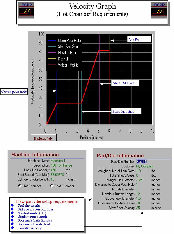
19 Chapter 7 Velocity Graph
20 Using the Velocity Graph 1.Enter all additional information required under Part/Die Information. The following definitions may assist in this process: Total Shot Weight: The total weight of all metal that enters the die during each shot. This includes all metal that goes through the gate, the runner system, and the biscuit or sprue. Distance to Cover Pour Hole: The distance required to advance the plunger past the metal fill hole in both hot chamber and cold chamber. Hot Chamber Variable Definitions: Nozzle Diameter: The inside diameter of the nozzle used. Nozzle + Button Length: The length of the nozzle plus the length of the button. Gooseneck Diameter: The inside diameter of the gooseneck used. Gooseneck to Metal Level: The length from the face of the gooseneck to the furnace metal level. Slow Shot Velocity: The slow shot velocity to be used for the given part
21 - 21 -
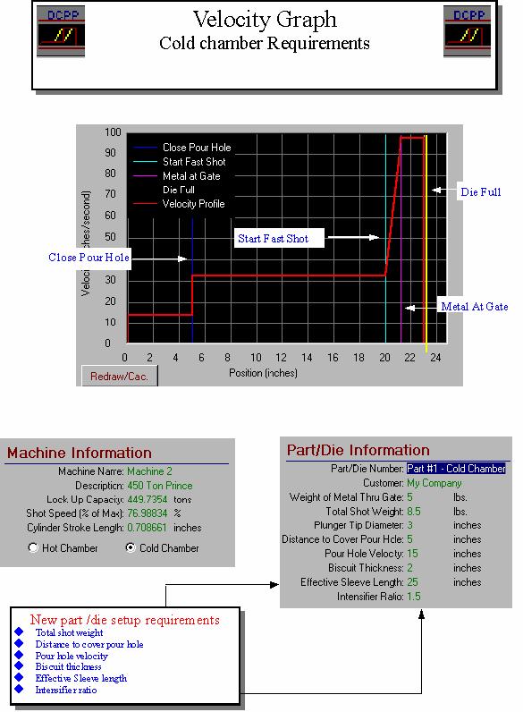
22 Cold Chamber Variable Definitions: Pour Hole Velocity: The plunger velocity required to pass the pour hole to avoid splashing metal out of the sleeve. Biscuit Thickness: The average thickness of the biscuit. Effective Sleeve Length: The distance from the face of the tip to the end of the sleeve. Intensifier Ratio: If a multiplication hydraulic circuit is used, this ratio is the pressure multiplication in the intensification circuit of your machine. If an intensifier bottle is used, this is the ratio of the intensifier bottle pressure to the shot bottle pressure
23 - 23 -
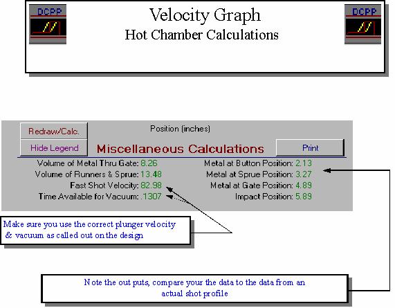
24 2. Select the Redraw/Calculate button. 3. Evaluate the Velocity Graph and calculations to assure that the process data entered are accurate. 4. Miscellaneous Calculations Descriptions Hot Chamber Variables: Volume of Metal Thru the Gate: The weight of the metal through the gate divided by the metal density. This value is used in the calculation of fill distance. Volume of Runners and Sprue: The result of the total shot weight minus the weight of the metal through the gate divided by the metal density. This value is used to calculate the distance between the Metal at Gate position and the Metal at Sprue position. Fast Shot Velocity: The plunger velocity during cavity fill. The calculation for fast shot velocity considers the plunger diameter, the required fill time, and the weight of the metal through the gate. Time Available for Vacuum: The amount of time from the start of the shot to the Metal at Sprue Position. Metal at Button Position: The calculated plunger position when the metal front gets to the button. Metal at Sprue Position: The calculated plunger position when the metal front gets to the end of the nozzle. Metal Gate Position: The calculated plunger position when the metal front gets to the in-gate of the die cavity. Impact Position: The calculated plunger position when the cavity is entirely full
25 - 25 -
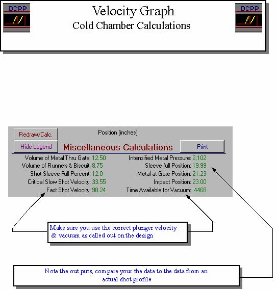
26 Cold Chamber Variables: Volume of Metal Thru the Gate: The weight of the metal through the gate divided by the metal density. This value is used in the calculation of cavity fill distance. Volume of Runners & Biscuit: The result of the total shot weight minus the weight of the metal through the gate divided by the metal density. This value is used to calculate the distance between the Metal at Gate position and the Sleeve Full position. Shot Sleeve Full Percentage: The total shot weight divided by the effective volume of the sleeve multiplied by 100. The effective volume of the sleeve is calculated from the die side of the pour hole to the end of the sleeve. Critical Slow Shot Velocity: The slow shot velocity required to minimize air entrapment within the metal that enters the die cavity. This is calculated based upon Garber s Fluid Flow Model within a die casting sleeve. Fast Shot Velocity: The plunger velocity during cavity fill. The calculation for fast shot velocity considers the plunger diameter, the required fill time, and the weight of the metal through the gate. Intensified Metal Pressure: The metal pressure during the intensification phase of the shot. It is calculated by multiplying the static metal pressure by the intensifier ratio. Sleeve Full Position: The calculated plunger position when the metal front gets to the base of the runner. Metal Gate Position: The calculated plunger position when the metal front gets to the in-gate of the die cavity. Impact Position: The calculated plunger position when the cavity is entirely full. Time Available for Vacuum: The amount of time from the Distance to Cover the Pour Hole to the Metal at Sprue Position
27 - 27 -
28 Chapter 8 Sample Tool 1. Set up the tool using the data from the design model and velocity graph calculations. Assure that the following are set properly: a) Tool is in the chosen machine. b) Chosen gooseneck or sleeve and plunger are set in the machine. c) Accumulator pressure and pre-charge are correct. d) Shot speed setting is correct. 2. Preheat tool to desired temperature. 3. Install monitoring equipment. a) Position transducer b) Pressure transducer (head side) c) Pressure transducer (rod side) 4. Collect data using monitoring equipment while focusing on the averages during cavity fill and the overall shot profile. Collect data on the following: a) Average fast shot velocity during cavity fill b) Average hydraulic head pressure during cavity fill c) Average hydraulic rod pressure during cavity fill d) Weight of all metal passing through the gate e) Total shot weight f) Slow shot velocity g) Pour hole velocity (if cold chamber) 5. Manually measure the in-gate area and the actual projected area. 6. Enter the above data into the Actual Model
 Actual operating pressure b) Actual fast shot plunger velocity c) Actual measured")
 Verify all other part/die and machine information to be correct 3. Review the Actual Model Cavity Fill Calculations.")
29 Chapter 9 Actual Model Using the Actual Model 1. Verify that the proper machine appears in the Actual Model machine used. 2. Enter the following Part/Die Information: a) Actual operating pressure b) Actual fast shot plunger velocity c) Actual measured gate area d) Actual hydraulic head pressure measured during cavity fill e) Actual hydraulic rod pressure measured during cavity fill f) Verify all other part/die and machine information to be correct 3. Review the Actual Model Cavity Fill Calculations
 If the results do not match or if the quality results were not acceptable, then make adjustments as follows: i) If your parts have mis-runs or poor fill, use DCPP to consider one or more of the")
30 a) Compare results to the design model. b) If the results match your design intent and the quality results of your sample were acceptable, then you have successfully used DCPP to design your process. c) If the results do not match or if the quality results were not acceptable, then make adjustments as follows: i) If your parts have mis-runs or poor fill, use DCPP to consider one or more of the following strategies: Reduce fill time by increasing your fast shot velocity. (Note: increasing fast shot velocity will also increase gate velocity. Therefore you may also need to increase the gate area to avoid excessive gate velocity.) Increase metal temperature to increase heat into the die. Increase die temperature in the problem area by reducing internal or external cooling or by adding hot oil. ii) If your parts have excessive internal shrinkage porosity, use DCPP to consider one or more of the following strategies: Increase gate velocity by reducing gate area or by increasing fast shot velocity. (Note: increasing fast shot velocity will also reduce fill time.) Increase metal pressure by reducing plunger tip diameter. (Note: you should verify and adjust for the effect of reduced plunger diameter.) Reduce metal temperature to reduce required intensification
31 Increase intensification pressure. Reduce the intensification rise time from impact to peak intensification pressure. iii) If your parts have excessive gas porosity, use DCPP to verify that the actual slow shot velocity is the same as the critical slow shot velocity. You may also try the following strategies: Test slow shot velocities slightly greater than and less than the critical slow shot velocity (+/- 1 to 2 inches per second). Reduce plunger tip lubricant (cold chamber). Reduce die spray in the problem area. Increase die temperature in the problem area. Using Discharge Coefficient DCPP is unique because it allows for mathematical calculation of discharge coefficient from actual process data. The discharge coefficient of kinetic friction is affected by the cavity geometry, runner geometry, plunger tip size, tip to sleeve drag, shot end hydraulic fluid drag, hydraulic piston drag, and leakage from head side to rod side within cylinder. The actual discharge coefficient is a valuable gauge of shot end performance over time and for evaluation of an individual die s gating system. Using SPC charting, someone in your company should track discharge coefficient by machine and by die so that problems can be detected and resolved with hydraulic cylinders, shot sleeves, and plunger tips. In addition, discharge coefficient should be tracked so that the representation of discharge coefficient in the design model can become more accurate for each of your machines over time
32 Chapter 10 DCPP Databases There are two databases that are maintained by DCPP. These are the Machine Database and Part Database. The Machine Database only includes machine capability data. However, the Part Database includes the Part/Die Information and the Machine Information. This is because the discharge coefficient, which is very important in process evaluation, is a function of the machine and the die. Therefore, each job must be saved with all the machines in which it will run. You may view either of these two databases by pressing the Machine and Part Database icons at the top of the main menu
Improve quality, reduce scrap & determine machine efficiency
 Process Monitoring Quality castings, understand variation causes. Improve quality, reduce scrap & determine machine efficiency Monitor, archive, and analyze shot data from multiple machines and give your
OWNER S MANUAL SUPPLEMENT for Performance Computer with VFD display. New Features. Metric Operation. Metric/US config
 c OWNER S MANUAL SUPPLEMENT for Performance Computer with VFD display New Features Metric Operation New G-Meter Display Options 2-5 Other Improvements 6-7 Metric/US config Setup for Metric use 8-9 Metric
Medium Size Die Casting Machine
 Medium Size Die Casting Machine UBE GLOBAL NETWORK With Japan as our headquarters, we contribute to our customers' globalization with a four-forked system covering Asia, North America and Europe. UBE Machinery
1. DESCRIPTION Two-Platen Cold Chamber Aluminium High Pressure Die Casting Machine Series REVOLUTION Model OL 1800 R
 1. DESCRIPTION Two-Platen Cold Chamber Aluminium High Pressure Die Casting Machine Series REVOLUTION Model OL 1800 R 2. TECHNICAL SPECIFICATIONSDIE CASTING MACHINE TECHNICAL DATERIES Brand: Idra Model:
Chapter 7: DC Motors and Transmissions. 7.1: Basic Definitions and Concepts
 Chapter 7: DC Motors and Transmissions Electric motors are one of the most common types of actuators found in robotics. Using them effectively will allow your robot to take action based on the direction
NEW TECHNOLOGIES IN COLD CHAMBER DIE CASTING PROCESS ACCORDING TO INDUSTRY 4.0
 NEW TECHNOLOGIES IN COLD CHAMBER DIE CASTING PROCESS ACCORDING TO INDUSTRY 4.0 Jürgen Lamparter Director Sales Cold Chamber Die Casting Machines Oskar Frech GmbH + Co. KG, 73614 Schorndorf, Germany AGENDA
COMPUTER AIDED FEEDING SYSTEM DESIGN FOR PRESSURE DIECASTING
 COMPUTER AIDED FEEDING SYSTEM DESIGN FOR PRESSURE DIECASTING Dissertation submitted in the partial fulfillment of the requirements for the degree of Master of Technology In Mechanical Engineering Submitted
Test Which component has the highest Energy Density? A. Accumulator. B. Battery. C. Capacitor. D. Spring.
 Test 1 1. Which statement is True? A. Pneumatic systems are more suitable than hydraulic systems to drive powerful machines. B. Mechanical systems transfer energy for longer distances than hydraulic systems.
Describe the function of a hydraulic power unit
 Chapter 7 Source of Hydraulic Power Power Units and Pumps 1 Objectives Describe the function of a hydraulic power unit and identify its primary components. Explain the purpose of a pump in a hydraulic
VARIABLE DISPLACEMENT OIL PUMP IMPROVES TRACKED VEHICLE TRANSMISSION EFFICIENCY
 2018 NDIA GROUND VEHICLE SYSTEMS ENGINEERING AND TECHNOLOGY SYMPOSIUM POWER & MOBILITY (P&M) TECHNICAL SESSION AUGUST 7-9, 2018 NOVI, MICHIGAN VARIABLE DISPLACEMENT OIL PUMP IMPROVES TRACKED VEHICLE TRANSMISSION
COMPACT CYLINDER CYLINDER FORCE AND WEIGHT TABLE BASE WEIGHT EFFECTIVE AREA
 CRS COMPACT CYLINDER STROKE TOLERANCE TEMPERATURE LIMITS VELOCITY LIFE EXPECTANCY SERIES CRS 1 psi min to 15 psi max at zero load [.7 bar min to 1 bar max] air.31 inch [.8 mm] -2 to +18 F [-28 to +82 C]
View Numbers and Units
 To demonstrate the usefulness of the Working Model 2-D program, sample problem 16.1was used to determine the forces and accelerations of rigid bodies in plane motion. In this problem a cargo van with a
Air Cylinders Drive System Full Stroke Time & Stroke End Velocity. How to Read the Graph
 1-1 Best Pneumatics Air Cylinders Drive System Full Time & End Velocity How to Read the Graph This graph shows the full stroke time and stroke end velocity when a cylinder drive system is composed of the
INJECTION MOULDING TROUBLESHOOTING GUIDE
 Page : 1 / 12 BLACK SPECKS OR STREAKS Excessive residence time in the barrel Hang-up of Molten material in the injection barrel or runner system Contamination of the injection barrel Degradation due to
Machine shut-off nozzle for Elastomer; Type-E Integrated actuator and tempering system
 Machine shut-off nozzle for Elastomer; Type-E Integrated actuator and tempering system Application: Elastomeric plastics Shut-off technique: Integrated two way pneumatic actuator Characteristics: Integrated
Seals Stretch Running Friction Friction Break-Out Friction. Build With The Best!
 squeeze, min. = 0.0035 with adverse tolerance build-up. If the O-ring is made in a compound that will shrink in the fluid, the minimum possible squeeze under adverse conditions then must be at least.076
Variable-speed drive solutions: Less current, less noise, less costs.
 Variable-speed drive solutions: Less current, less noise, less costs. Variable-speed drives connect standard components from hydraulic and electric systems to form customized, intelligent and cost-efficient
Pump Control Ball Valve for Energy Savings
 VM PCBVES/WP White Paper Pump Control Ball Valve for Energy Savings Table of Contents Introduction............................... Pump Control Valves........................ Headloss..................................
Other significant updates include:
 THE NEW N.F.P.A. 1962 The NFPA recently revised its standard on fire hose. The newest edition requires that hose manufactured before July 1987 be removed from service. This makes sense given all the changes
Air Cylinders Drive System Full Stroke Time & Stroke End Velocity. How to Read the Graph
 1 Best Pneumatics Air Cylinders Drive System Full Time & End Velocity How to Read the Graph This graph shows the full stroke time and stroke end velocity when a cylinder drive system is composed of the
Performance means how fast will it go? How fast will it climb? How quickly it will take-off and land? How far it will go?
 Performance Concepts Speaker: Randall L. Brookhiser Performance means how fast will it go? How fast will it climb? How quickly it will take-off and land? How far it will go? Let s start with the phase
MAGNA T SERVO. 500 to 5,500 kn
 MAGNA T SERVO 500 to 5,500 kn A NEW STANDARD IN TOGGLE TECHNOLOGY Energy Efficient, Rugged & Reliable, Precise & Consistent, Versatile & User Friendly MAGNA T SERVO TOGGLE INJECTION MOLDING MACHINE Durable
SECTION A: INTRODUCTION
 SECTION A: INTRODUCTION Overview of the Injected Metal Assembly (IMA ) process Fishertech s Injected Metal Assembly process combines assembly techniques with specialized die casting technology to increase
IntelliMold Systems OEM Integration: Van Dorn Revision Level: 002 Document Number:
 IntelliMold Systems OEM Integration: Van Dorn Revision Level: 002 Document Number: 7.5.1.0.30.002 The following information is for reference only. It is subject to change and may not be identical on all
CONTRIBUTION TO THE CINEMATIC AND DYNAMIC STUDIES OF HYDRAULIC RADIAL PISTON MOTORS.
 Ing. MIRCEA-TRAIAN CHIMA CONTRIBUTION TO THE CINEMATIC AND DYNAMIC STUDIES OF HYDRAULIC RADIAL PISTON MOTORS. PhD Thesis Abstract Advisor, Prof. dr. ing. matem. Nicolae URSU-FISCHER D.H.C. Cluj-Napoca
Understanding the benefits of using a digital valve controller. Mark Buzzell Business Manager, Metso Flow Control
 Understanding the benefits of using a digital valve controller Mark Buzzell Business Manager, Metso Flow Control Evolution of Valve Positioners Digital (Next Generation) Digital (First Generation) Analog
BRAKE SYSTEM DESIGN AND THEORY
 RAKE SYSTEM DESIGN AND THEORY Aircraft brake systems perform multiple functions. They must be able to hold the aircraft back at full static engine run-up, provide adequate control during ground taxi operations,
EASY TO USE POWERFUL & FLEXIBLE
 EASY TO USE POWERFUL & FLEXIBLE ENERGY SAVING DCC130- Cold Chamber Die Casting Machine LK Website:www.lktechnology.com COLD CHAMBER DIE CASTING MACHINE Hydraulic Driven Die Height Adjustment Clamping State
VALVES & ACTUATORS. 20th TECHNOLOGY REPORT. SOLUTIONS for FLUID MOVEMENT, MEASUREMENT & CONTAINMENT. HOW MUCH PRESSURE Can a 150 lb. Flange Withstand?
 TOP REASONS to Manage Corrosion PROS & CONS of Volumetric Flowmeters HOW MUCH PRESSURE Can a 150 lb. Flange Withstand? 20th 19 9 5-2 015 SOLUTIONS for FLUID MOVEMENT, MEASUREMENT & CONTAINMENT special
FUEL AND LUBRICATION SYSTEM
 AND LUBRICATION SYSTEM 4-1 A-PDF Split DEMO : Purchase from www.a-pdf.com to remove the watermark AND LUBRICATION SYSTEM CONTENTS SYSTEM... 4-2 PUMP... 4-2 TANK/ COCK... 4-3 REMOVAL... 4-3 INSPECTION...
Air/Oil Tanks Air Boosters Cylinder Options Multi-Stage Triple-Rod Basic Cylinders Accessories Technical Data TECHNICAL DATA: FORCE CHART BORE STROKE
 How to determine the right size Cylinder for the job TECHNICAL DATA To determine what size cylinder the task requires, you need to answer a few questions about three main points: load, velocity and air
Module 4: Actuators. CDX Diesel Hydraulics. Terms and Definitions. Cylinder Actuators
 Terms and Definitions Cylinder Actuators Symbols for Actuators Terms and Definitions II Cylinders Providing Linear Motion Cylinders Providing Angular Motion Parts of Actuators Mounting of Actuators Seals
Heat Engines Lab 12 SAFETY
 HB 1-05-09 Heat Engines 1 Lab 12 1 i Heat Engines Lab 12 Equipment SWS, 600 ml pyrex beaker with handle for ice water, 350 ml pyrex beaker with handle for boiling water, 11x14x3 in tray, pressure sensor,
Crankcase scavenging.
 Software for engine simulation and optimization www.diesel-rk.bmstu.ru The full cycle thermodynamic engine simulation software DIESEL-RK is designed for simulating and optimizing working processes of two-
SHAFT ALIGNMENT FORWARD
 Service Application Manual SAM Chapter 630-76 Section 24 SHAFT ALIGNMENT FORWARD One of the basic problems of any installation is aligning couplings or shafts. Therefore, this section will endeavor to
Motor-CAD End Winding Spray Cooling Model
 Motor-CAD End Winding Spray Cooling Model Description Motor spray cooling is where the end winding is cooled by passing a fluid down the shaft and then firing it at the end winding through nozzles at the
Template for the Storyboard stage
 Template for the Storyboard stage Animation can be done in JAVA 2-D. Mention what will be your animation medium: 2D or 3D Mention the software to be used for animation development: JAVA, Flash, Blender,
The DPC Digital Clamp Controller
 Electric Drives and Controls Linear Motion and Assembly Technologies Pneumatics Service The DPC Digital Clamp Controller The Drive & Control Company 1 Clamping Units Moving Large Masses Smoothly with Speed
Automotive Application ET01 Software Revision A 12/06
 Automotive Application ET01 Software Revision A 12/06 INTRODUCTION... 2 FUNCTIONAL DESCRIPTION... 3 INSTALLATION... 4 COMPONENT PLACEMENT... 4 PLUMBING AND WIRING... 5 MSBC OPERATION (ET-01)... 14 TIMED
SchuF FETTEROLF SchuF / Fetterolf standard Type 32 sampling valves custom-built solutions
 FETTEROLF SchuF / Fetterolf offers a large range of sampling valve solutions. Our standard Type 32 sampling valves are available from stock for fast deliveries. We also offer custom-built solutions. Either
Jon Konings Former CEM Coordinator
 Jon Konings Former CEM Coordinator Not covering every detail of these QA topics. There is such a wide variation in the configuration of hardware out there, and I can t cover everything, so I will address
INSTALLATION INSTRUCTIONS
 INSTALLATION INSTRUCTIONS BIG ROTOR / CALIPER RELOCATION FRONT KITS SUM-BK1422, BK1423, BK1424 1999-2006 GM 1/2 Ton Trucks & SUVs Thank you for choosing SUMMIT RACING for your braking needs. Pleases take
Best Practice Variable Speed Pump Systems
 Best Practice Variable Speed Pump Systems Contents 1 Introduction 3 General Recommendations 4 2 Pumping Systems 6 3 Effects of Speed Variation 8 4 Variable Speed Drives 9 5 Financial Savings 11 Introduction
SECTION I: INDEX. Accumulator, injection B1-15 maintenance G1-12. Cable termination equipment A-3
 SECTION I: INDEX A Accumulator, injection B1-15 maintenance G1-12 Alignment, nozzle seat/nozzle tip E- 4 checking G1-18 correcting poor alignment G1-18 procedure, nozzle alignment G1-16 Alloy D-3 contamination
SECTION B: SYSTEM OPERATING COMPONENTS
 SECTION B: SYSTEM OPERATING COMPONENTS A brief description of the machine, Cable Processor Module and tooling will provide a better understanding of the various functions of the IMA system. SECTION B1:
Carat. The solution with highest value creation for sophisticated parts. Innovations for a better world.
 The solution with highest value creation for sophisticated parts. Innovations for a better world. Reliable solution for higher casting performance. The integrated die casting solution for components with
EQUAL DISTRIBUTION OF WASTEWATER USING LOW-PRESSURE DISTRIBUTION Larry D. Stephens, P.E. *
 EQUAL DISTRIBUTION OF WASTEWATER USING LOW-PRESSURE DISTRIBUTION Larry D. Stephens, P.E. * INTRODUCTION Experience with onsite systems has proven that equal application of wastewater over the entire soil
Sizing criteria for cylinders and servocylinders
 www.atos.com Table B15-15/E Sizing criteria for cylinders and servocylinders 1 SWC Cylinders Designer SWC is a smart software for fast and efficient design of Atos hydraulic Cylinders & Servocylinders,
Analysis. Techniques for. Racecar Data. Acquisition, Second Edition. By Jorge Segers INTERNATIONAL, Warrendale, Pennsylvania, USA
 Analysis Techniques for Racecar Data Acquisition, Second Edition By Jorge Segers INTERNATIONAL, Warrendale, Pennsylvania, USA Preface to the Second Edition xiii Preface to the First Edition xv Acknowledgments
Application Information
 Moog Components Group manufactures a comprehensive line of brush-type and brushless motors, as well as brushless controllers. The purpose of this document is to provide a guide for the selection and application
11 % 19 % About Standard Diesel 2.9B. mpg. The Evolving Diesel Engine. The Most Comprehensive Diesel Program in the Marketplace
 About Standard Diesel The Evolving Diesel Engine Diesel engines have come a long way since the mid-90s. The key to diesel s evolution has been the advancement of new clean diesel technologies. Today s
IMPACT REGISTER, INC. PRECISION BUILT RECORDERS SINCE 1914
 IMPACT REGISTER, INC. PRECISION BUILT RECORDERS SINCE 1914 RM-3WE (THREE WAY) ACCELEROMETER GENERAL The RM-3WE accelerometer measures and permanently records, for periods of 30, 60, and 90 days, the magnitude,
SEEV-A HD High-Duty, Advanced All-Electric Series. 8 model sizes from 247 to 562 U.S. tons
 SEEV-A HD High-Duty, Advanced All-Electric Series 8 model sizes from 247 to 562 U.S. tons SEEV-A HD Series Advanced, High-Duty All-Electrics 8 model sizes from 247 to 562 U.S. tons With the new SEEV-A
SECTION I: INDEX. Accumulator, injection B1-15 maintenance G1-26
 SECTION I: INDEX A Accumulator, injection B1-15 maintenance G1-26 Alignment, nozzle seat/nozzle tip E- 4 checking G1-33 correcting poor alignment G1-33 procedure, nozzle alignment G1-31 Alloy D-3 contamination
Penn Valley Pump Company Design Information for Double Disc Pumps
 Penn Valley Pump Company Design Information for Double Disc Pumps INTRODUCTION The Penn Valley Double Disc Pump utilizes a unique principle of operation whereby the discs perform the duties of pumping
UPGRADE YOUR BLOW MOLDING MACHINE WITH ONE OF OUR TWO NEW STATE OF THE ART MACHINE CONTROL SYSTEMS.
 UPGRADE YOUR BLOW MOLDING MACHINE WITH ONE OF OUR TWO NEW STATE OF THE ART MACHINE CONTROL SYSTEMS. Uniloy is proud to introduce the Allen Bradley Compact Logix, and B&R Control Packages developed for
IMPROVING SULFURIC ACID PLANT PERFORMANCE THROUGH NEW SHAPE & HIGHER ACTIVITY CATALYSTS
 IMPROVING SULFURIC ACID PLANT PERFORMANCE THROUGH NEW SHAPE & HIGHER ACTIVITY CATALYSTS BY: TIMOTHY R. FELTHOUSE, Ph.D; MARIO P. DIGIOVANNI, P.E.; JOHN R. HORNE AND SARAH A. RICHARDSON PRESENTED AT: THE
PURe Mix Technology for Mixing and Metering
 PURe Mix Technology for Mixing and Metering For a PURe variety of applications FRIMO PURe Mix Technology for Mixing and Metering Having more than 40 years of experience in production technology for the
FUNDAMENTALS OF ORIFICE METERING Ken Embry FMC Measurement Solutions
 FUNDAMENTALS OF ORIFICE METERING Ken Embry FMC Measurement Solutions 6677 N. Gessner, Houston, Texas 77040 Throughout the oil and gas industry, there stems the need for accurate, economical measurement
GRADE 7 TEKS ALIGNMENT CHART
 GRADE 7 TEKS ALIGNMENT CHART TEKS 7.2 extend previous knowledge of sets and subsets using a visual representation to describe relationships between sets of rational numbers. 7.3.A add, subtract, multiply,
INSTALLATION INSTRUCTIONS
 INSTALLATION INSTRUCTIONS BIG ROTOR / CALIPER RELOCATION REAR KIT SUM-BK1423 1999-2009 GM 1/2 Ton Trucks & SUVs Thank you for choosing SUMMIT RACING for your braking needs. Pleases take the time to read
Chapter 1. Introduction. manufacturing metal goods [1]. In most of the early casting processes, some of which
![Chapter 1. Introduction. manufacturing metal goods [1]. In most of the early casting processes, some of which](/thumbs/86/93855680.jpg "Chapter 1. Introduction. manufacturing metal goods [1]. In most of the early casting processes, some of which") Chapter 1 Introduction Casting processes are among the oldest (around 5000 B.C.) methods for manufacturing metal goods [1]. In most of the early casting processes, some of which are still applicable today,
Chapter 1 Introduction Casting processes are among the oldest (around 5000 B.C.) methods for manufacturing metal goods [1]. In most of the early casting processes, some of which are still applicable today,
Silencers. Transmission and Insertion Loss
 Silencers Practical silencers are complex devices, which operate reducing pressure oscillations before they reach the atmosphere, producing the minimum possible loss of engine performance. However they
CHAPTER 4 : RESISTANCE TO PROGRESS OF A VEHICLE - MEASUREMENT METHOD ON THE ROAD - SIMULATION ON A CHASSIS DYNAMOMETER
 CHAPTER 4 : RESISTANCE TO PROGRESS OF A VEHICLE - MEASUREMENT METHOD ON THE ROAD - SIMULATION ON A CHASSIS DYNAMOMETER 1. Scope : This Chapter describes the methods to measure the resistance to the progress
DEPARTMENT OF LICENSING AND REGULATORY AFFAIRS DIRECTOR'S OFFICE GENERAL INDUSTRY SAFETY STANDARDS
 DEPARTMENT OF LICENSING AND REGULATORY AFFAIRS DIRECTOR'S OFFICE GENERAL INDUSTRY SAFETY STANDARDS (By authority conferred on the director of the department of licensing and regulatory affairs by sections
Four-Quadrant Multi-Fluid Pump/Motor
 Georgia Institute of Technology Marquette University Milwaukee School of Engineering North Carolina A&T State University Purdue University University of California, Merced University of Illinois, Urbana-Champaign
KISSsoft 03/2018 Tutorial 4
 KISSsoft 03/2018 Tutorial 4 Bolt calculation according to VDI 2230 KISSsoft AG T. +41 55 254 20 50 A Gleason Company F. +41 55 254 20 51 Rosengartenstr. 4, 8608 Bubikon info@kisssoft.ag Switzerland www.kisssoft.ag
OPERATOR'S MANUAL AND MAINTENANCE INFORMATION MODEL T-2000 TEXTURE TEST SYSTEM
 OPERATOR'S MANUAL AND MAINTENANCE INFORMATION MODEL T-2000 TEXTURE TEST SYSTEM This Publication contains information proprietary To Food Technology Corporation The contents of this publication may not
Thermal Stress Analysis of Diesel Engine Piston
 International Conference on Challenges and Opportunities in Mechanical Engineering, Industrial Engineering and Management Studies 576 Thermal Stress Analysis of Diesel Engine Piston B.R. Ramesh and Kishan
Introduction. Materials and Methods. How to Estimate Injection Percentage
 How to Estimate Injection Percentage Introduction The Marel IN33-3 injector for pork bellies is a 5 needle, low-pressure conveyor type machine which utilizes a 3-gpm positive displacement pump and control
Components of Hydronic Systems
 Valve and Actuator Manual 977 Hydronic System Basics Section Engineering Bulletin H111 Issue Date 0789 Components of Hydronic Systems The performance of a hydronic system depends upon many factors. Because
The ROBUST Performer
 80 to 910 Ton The ROBUST Performer Energy Efficient Generous Specifications Robust & Reliable User Friendly Control The ROBUST Performer 3 Large Ram Diameter Provides Uniform Force Distribution across
Upgrade your blow molding machine with one of our two new state of the art machine control systems.
 Upgrade your blow molding machine with one of our two new state of the art machine control systems. Uniloy is proud to introduce the Allen Bradley Compact Logix, and B&R Control Packages developed for
Design & Development of Regenerative Braking System at Rear Axle
 International Journal of Advanced Mechanical Engineering. ISSN 2250-3234 Volume 8, Number 2 (2018), pp. 165-172 Research India Publications http://www.ripublication.com Design & Development of Regenerative
Servo/Hydraulic Press Brake With Patented Automatic Tool Changer HG 1003 ATC
 Servo/Hydraulic Press Brake With Patented Automatic Tool Changer HG 1003 ATC HG 1003 ATC Press Brake with Patented Automatic Tool Changer Introduce rush jobs seamlessly Triple or quadruple the amount of
The filling pressure of SUSPA gas springs depends on the extension force and the geometry and is between 10 and 230 bar.
 FAQ s 1. Why is there a warning on the gas spring? Gas springs are filled with compressed nitrogen. The warning is intended to prevent unauthorized people from opening the gas spring or making other changes
Variable Speed Drive on a Die Casting Machine
 Design & Engineering Services Variable Speed Drive on a Die Casting Machine 0 Report Prepared by: Design & Engineering Services Customer Service Business Unit Southern California Edison December 17, 2010
Influence of Cylinder Bore Volume on Pressure Pulsations in a Hermetic Reciprocating Compressor
 Purdue University Purdue e-pubs International Compressor Engineering Conference School of Mechanical Engineering 2014 Influence of Cylinder Bore Volume on Pressure Pulsations in a Hermetic Reciprocating
Quick Start User Guide
 Quick Start User Guide 2 Pipe Flow Expert Quick Start Guide Copyright Notice 2015 All Rights Reserved Daxesoft Ltd. Owner of PipeFlow.co.uk and PipeFlow.com Distribution Limited to Authorized Persons Only.
Programmable Comparator Options for the isppac-powr1220at8
 November 2005 Introduction Application Note AN6069 Lattice s isppac -POWR1220AT8 offers a wide range of features for managing multiple power supplies in a complex system. This application note outlines
SE-DUZ Direct-Drive All-Electric Series
 SE-DUZ Direct-Drive All-Electric Series SE-DUZ Series Direct-Drive All-Electrics Low-inertia, high-performance direct-drive motors for plasticizing, injection, clamping and ejection New PC-based control
CHAPTER-3 EXPERIMENTAL SETUP. The experimental set up is made with necessary. instrumentations to evaluate the performance, emission and
 95 CHAPTER-3 EXPERIMENTAL SETUP The experimental set up is made with necessary instrumentations to evaluate the performance, emission and combustion parameters of the compression ignition engine at different
2.61 Internal Combustion Engines
 Due: Thursday, February 19, 2004 2.61 Internal Combustion Engines Problem Set 2 Tuesday, February 10, 2004 1. Several velocities, time, and length scales are useful in understanding what goes on inside
Piping Systems in Dewatering Applications
 Piping Systems in Dewatering Applications Pump System Improvement by Ray Hardee Engineers involved with any project that includes more than a cursory amount of digging must consider how to manage groundwater.
Free-CHP: Free-Piston Reciprocating Joule Cycle Engine
 PRO-TEM Special Session on Power Generation and Polygeneration Systems Free-CHP: Free-Piston Reciprocating Joule Cycle Engine Rikard Mikalsen, Tony Roskilly Newcastle University, UK Background: micro-chp
We shut the air supply down to our clamps once they are in position. Sometimes we notice that they are sticking. Could this be the cause?
 Frequently Asked Questions B-1 Following are some of the questions we have been asked while developing the VektorAir TM line. Please read them carefully before planning your system. Many common problems
Air Brakes From Real Trains
 Air Brakes From Real Trains Real Trains has been producing air brake systems for our 1 1/2 scale trucks for more than seventeen years. In this time over 100 pairs of trucks equipped with air brakes have
ESCONDIDO FIRE DEPT TRAINING MANUAL Section DRIVER OPERATOR Page 1 of 13 Pumps and Accessory Equipment Revised
 DRIVER OPERATOR Page 1 of 13 PUMPS AND ACCESSORY EQUIPMENT Pumps are designed for many different purposes. In order to understand the proper application and operation of a pump in a given situation, firefighters
Hydronic Corporation
 Hydronic Corporation Air Driven Hydraulic Pumps and Intensifiers P825 Installation, Use and Maintenance Manual Contents Introduction, Guarantee and Identification Plate Description, Start Up Procedures
AR2000 Rheometer: Instructions
 AR2000 Rheometer: Instructions Instrument Setup Note: The order in which the things are powered on is very important! 1. Check to make sure the Smart Swap cable is connected to the machine. 2. Make sure
Chapter 2 Dynamic Analysis of a Heavy Vehicle Using Lumped Parameter Model
 Chapter 2 Dynamic Analysis of a Heavy Vehicle Using Lumped Parameter Model The interaction between a vehicle and the road is a very complicated dynamic process, which involves many fields such as vehicle
SAE Baja - Drivetrain
 SAE Baja - Drivetrain By Ricardo Inzunza, Brandon Janca, Ryan Worden Team 11 Engineering Analysis Document Submitted towards partial fulfillment of the requirements for Mechanical Engineering Design I
KE-M02 configuration Configuratie documentatie documentation KE-M02
 Configuratie documentatie KE-M02 1/32 2/32 3/32 4/32 5/32 General Technical Data for Compact Power Module KE series Through the years DCOC has developed a highly evolved modular system resulting in powerful,
4.1 Flow Rate Verification and Adjustment
 4.1 Flow Rate Verification and Adjustment Once the pressure verification is complete (see Chapter 3), the gas flow rate should be verified. Accurate gas flow through the nozzle is critical for achieving
MultiCam 3000 Series CNC Router Feature and Specification Guide. Versatile, Feature-Rich Production Routing! The MultiCam. Ideal for Cutting: Wood
 MultiCam 3000 Series CNC Router Feature and Specification Guide Versatile, Feature-Rich Production Routing! The MultiCam 3000 Series CNC Routers are loaded with standard features normally associated with
TuffCam Swing Clamps C-1. Frequently Asked Questions
 Frequently Asked Questions C-1 When do you recommend the use of TuffCam Swing Clamps over the standard product? Applications where speed is essential, massive arms are required, or position sensing is
Servo/Hydraulic Press Brake With Automatic Tool Changer HG 1003 ATC
 Servo/Hydraulic Press Brake With Automatic Tool Changer HG 1003 ATC HG 1003 ATC Press Brake with Automatic Tool Changer Introduce rush jobs seamlessly Triple or quadruple the amount of setups performed
Electric. Efficient. Compact & precise. ENGEL e-mac
 Electric. Efficient. Compact & precise. be the first. All-electric. Best-in-class efficiency and precision to the max. All of the s movements are performed by servo-electric drives. The all-electric drive
Series Accumulators/ Nuclear Actuators. Series Accumulators/ Nuclear Actuators
 Series Accumulators/ Nuclear Actuators Series Accumulators/ Nuclear Actuators Series AccumulatorS/Nuclear Actuators 7 8 9 10 11 12 Accumulators Sleeve Bladder Type Gas Gauge OIL 1. High strength steel
Cylinders. Standard Features F-1. Frequently Asked Questions, Features
 Frequently Asked Questions, Features Why use Cylinders? Cylinders are the most common and least costly form of hydraulic clamping avail able. They can be sized adequately to allow you to clamp across or