Conductor Bar Selection
|
|
|
- Christine Bryant
- 5 years ago
- Views:
Transcription
1
2 U L LISTED File # E29805 Contr. 678L Approved in Canada Conductor Bar Selection Determining Ampere Load The conductor selected must be large enough to carry the necessary ampere load safely without undue heating. To compute the ampere load, proceed as follows: 1. List the horsepower of all motors used in the application. 2. Determine the voltage and type of current that will feed the conductor. For example: 230v dc 2 wire; 460v ac 3 phase; etc. 3. Refer to the Horsepower Conversion Table on page 3 and convert the horsepower to amperes. 4. Prepare the ampere load figure that will be used to size the conductors as follows: List the full load ampere rating of each motor used on the crane or monorail unit. Determine the duty cycle from the following paragraphs and apply the corresponding factor. Light Duty Class A and B Crane Service Standby or infrequent use. Up to two motors started at a time. Two to five lifts per hour. Use a factor of 90% of the calculated ampere load. Average Duty Class C Crane Service Moderate use during the work day. Five to ten lifts per hour. Not over 50% of the lift at rated capacity. Use a factor of 100% of the calculated ampere load. Heavy Duty Class D Crane Service Used continually during the work day and usually for more than one shift. Loads of 50% of rated capacity or more handled constantly during the work period. Use a factor of 110% of the calculated ampere load. Severe Duty Class E and F Crane Service Used continually for two or more work shifts a day for loads approaching 100% of capacity. Use a factor of 120% of the calculated ampere load. Due to the mechanical considerations on severe duty use, contact the factory engineering group when selecting the conductor system for this application. 5. If the conductors are to be located where the ambient air temperature is unusually high, the current carrying capacity of the conductor is reduced. Multiply the current capacity of the selected conductor by the derating factor in the following table. Temperature Derating Table Ambient Air Temperature Derating Factor 100 F 95% 130 F 75% 160 F* 50% * At this ambient temperature it will be neccessary to use the higher rated conductor cover, XHT rated at 280 F. Determining Voltage Drop According to CMAA, the voltage drop to the unit motors shall not be more than 3% from the power taps to the load at the farthest point on the conductor run. To determine the voltage drop use the appropriate formula in the following table. Current Type Formula AC 3 phase 60 cycle V = L x I x Z x 1.73 AC 1 or 2 phase 60 cycle V = L x I x Z x 2 DC 2 wire system V = L x I x R x 2 V = Voltage drop L = Distance from power feed to end of conductor I = Total amperes drawn as calculated from conversion charts Z = ac impedance R = dc resistance See Conductor Engineering Data Table on page 4 for values of Z and R. Divide voltage drop by system voltage to get the percent of voltage drop. Maximum voltage drops that are 3% of various supply voltages are as follows: Supply Voltage Voltage Drop (V) 460v ac v ac or dc v ac 17.2 Volts lost that are equal to or less than the above values when using the formulas above will help in selecting the correct conductor. 2
3 Conductor Selection Example Given a 300 foot runway, power fed at the center, using 460 volt, 3 phase, 60 cycle power supplied to a bridge crane there is a 40 h.p. hoist motor, a 20 h.p. bridge motor, and a 5 h.p. trolley motor. The operation is Average Duty. Ambient temperature varies from 50 F in winter to 90 F in summer on this Indoor installation. Step 1 Determining Ampere Load See National Electric Code article (e) for determining motor loads where there are multiple motors on a single crane. Then from the Horse Power Conversion Table 460v column (right): 40 h.p. hoist motor % = 52 amps 20 h.p. bridge motor 27 50% = 13.5 amps 5 h.p. trolley motor % = 3.8 amps The total current load is 69.3 amperes. With Average Duty cycle, the current load is factored at 100%. Normal ambient conditions of 50 F to 90 F require no temperature derating. Selecting a 90 amp conductor caused a voltage drop of 4.3% using the formula. Since this is unsatisfactory, use a 110 amp conductor (FE-908) for Step 2. Step 2 Determining Voltage Drop Use the AC 3 phase formula on page two. V = L x I x Z x 1.73 where: L = 150 ft. (Distance to the end of the runway from the center power feed.) I = 69.3 amperes Z =.0008 for 110 amp conductor (From the Conductor Engineering Data Table, page 4.) 1.73 = 3 phase constant V = 150 x 69.3 x.0008 x 1.73 = 14.4 volts 14.4/460 = 3.1% Since this voltage drop only occurs at the farthest end when two or more motors are started simultaneously, exceeding the 3% voltage drop goal by only 0.1% will not cause a problem. Horsepower Conversion Table 3 Phase AC 60 Cycle Direct Current Amperes Amperes H.P. 230v 460v 575v 230v 1/ / / / Ampere Load Calculations for Multiple Units For information about sizing ampere loads for multiple cranes on the same runway, see Article (e) of the National Electrical Code for the demand factors. This article also covers additional loads on the bridge cranes other than motor loads. Induction Type Squirrel Cage and Wound Rotor Motors The Horsepower Conversion Table is taken from the 1996 NEC Article 430. The values are for motors running at usual speeds with normal torque characteristics. Motors built for especially low speeds or high torques may require more running current, and multi-speed motors will have full-load current varying with speed. In these cases, use the higher nameplate current rating. The voltages listed are rated motor voltages. The current listed shall be permitted for system voltage ranges of 110 to 120, 220 to 240, 440 to 480, and 550 to 600 volts. Motors rated at 208v ac should increase the 230 volt column figures by 10%. For motors that are wound for single or double phase operation, use the nameplate rating. For older slip ring motors or models that have secondary windings be sure to obtain both primary and secondary current ratings. Secondary windings may also need separate conductors or cables when updating the electrification. 3
4 Conductor Engineering Data Table Weight per Ampere Rating Coefficient of Resistance Factor Conductor Description 10' section Linear Expansion AC (z) DC (R) Circular Bar No. lbs. Continuous Intermittent* per F ohms/ft. ohms/ft. Mills FE-758 Galvanized Steel ,000 FE-908 Galvanized Steel ,000 FE-1608 Stainless/Copper Laminate ,000 FE-2008 Copper/Steel Laminate ,000 FE-3008 Rolled Copper ,000 FE-5008 Extruded Copper ,000 * Intermittent Service Rating is determined for one minute on, one minute off operation. Miscellaneous Applications Curves Duct-O-Bars, except the Totally Enclosed System, can be bent to form curved sections without damaging the insulating cover or conductor. Bends with a five-foot radius or greater can be done in the field by using a fly wheel, monorail beam, or similar object to bend the conductor to approximately the necessary radius. Hangers used on curved sections must be placed at intervals of 2-1/2 feet maximium and closer if required. Use B-100 cross bolt clamp type hangers and P-Series collectors. The minimum spacing between conductors on curves is three inches. For curves of five-foot radius or more, use five-inch collector shoes. For curves of less than five-foot radius use three-inch collector shoes; also consult the factory for additional information. Discontinuous Circuits On discontinuous circuits a pickup guide assembly must be installed to ensure that the self-centering type collectors engage and disengage the conductor bar. The pickup guide (FE-2JNN3 is illustrated) must have its own support point. 3-1/2" 5' Max. DUCT-O-BAR Transfer Cap 10" Support Point Pickup Guide Assembly 3" Self-Centering Collector Interlocks, Switches, or Fixed Gaps The maximum fixed gap occurring at interlocks is one-inch when using 100 amp P-Series collectors and 1/2 inch when using 40 amp collectors. Use transfer caps as shown to ensure that the collector brushes transfer evenly and smoothly. Also round both ends of the contact brushes to facilitate the transfer. Use clamp type hangers only. When both interlocks and curves of less than a four-foot radius are encountered, the tandem 40 amp collector is recommended. Support Bracket 2-1/2" Transfer Cap 1" Max. Gap 100 AMP Collectors 1/2" Max. Gap 40 AMP Collectors Support Bracket Other Special Applications Consult the factory for recommendations on applications such as de-icing systems, totally enclosed systems, and other systems not covered here. 4

 = X/150' x Y/100 F where X is the runway length and Y is the 12 month temperature variation.")
5 Expansion Gaps Expansion gaps should be placed at intervals determined by 1) the expansion rate of the metal in the conductor selected, and 2) the variation in temperature that will occur at the conductor location over a full year of operation. 1. Steel Conductor Systems Given that steel conductors expand 1" for every 150' of runway with a temperature change of 100 F over a full year of operation, put the length of the runway and the maximum temperature change for the system to be used into the following formula: Total Steel Expansion (inches) = X/150' x Y/100 F where X is the runway length and Y is the 12 month temperature variation. Example: A 450' long steel conductor (X) installed in a building with an indoor temperature change of 40 F (Y). Total Expansion = 450'/150' x 40 F/100 F = 1.2". (See Section 3.) 2. Copper Conductor Systems Given that copper conductors expand 1" for every 100' of runway over a 100 F temperature change at the conductor over a full year of operation, put the length of the runway and the maximum temperature change for the system to be used into the following formula: Total Copper Expansion (inches) = X/100' x Y/100 F. Example: A 300' long copper conductor system (X) installed outdoors with an anticipated temperature fluctuation of 80 F (Y). Total Expansion = 300'/100' x 80 F/100 F = 2.4". (See Section 3.) 3. Determine the Number of Expansion Gap Assemblies After calculating the actual expansion of the runway conductor system, use the following rule of thumb to pick the number of expansion gap assemblies: a. Under 1" of expansion, use no expansion assemblies. Install one anchor clamp set at the center of the conductor run. b. From 1" to 2" of expansion, use one expansion assembly in the center of the conductor run. c. From 2" to 4" of expansion, use two expansion assemblies. Locate them at 1/3 of the runway length in from each end. d. For systems with more than 4" of expansion, use one expansion gap assembly for each 2" of expansion. 4. Anchors Anchor clamps are required at midpoint on all systems without expansion gaps and halfway between gaps and from gaps to the end of systems with multiple gaps. See the Figure 8 Installation Instructions on anchor locations. The maximum gap opening for all ten foot Figure 8 expansion gap assemblies is 1-3/4 inches. Expansion assemblies are also required at building expansion joints. Conductor Assembly Selection Duct-O-Wire Figure 8 Conductor Bars are furnished as assemblies consisting of a ten-foot long conductor bar rated at 600 volts, an insulating cover, splice cover, and connector pins or joint clamps as applicable. The insulating cover must be appropriate for the environment indoor, outdoor, or high temperature in which the conductor is to operate. Indoor systems are for use in ambient temperatures up to 160 F. They have an Orange PVC Insulating Cover. They are not recommended for outdoor use in direct sunlight. Outdoor systems are for use in direct sunlight and ambient temperatures up to 160 F. They have a Gray PVC Insulating Cover with an ultraviolet additive. High temperature systems are for use in ambient temperatures up to 280 F. They have a Yellow Lexan Insulating Cover. From the table to the right, you can select the basic (FE) conductor assembly with the appropriate bar and insulating cover for your application. For information on other conductor assemblies, see page 12. Basic Figure 8 (FE) Conductor Assemblies 10 ft. Lengths Assembly Catalog No. Conductor Weight Indoor Outdoor High Temp. Bar No. Pounds Use Use Use FE FE FE SC FE-758-2XHT FE FE FE SC FE-908-2XHT FE FE FE SC FE XHT FE FE FE SC FE XHT FE FE FE SC FE XHT FE FE FE SC FE XHT Cross-sectional drawing of Basic Figure 8 (FE) Conductor Assembly 5
6 Typical Conductor Mounting Note: S indicates minimum conductor spacing. Standard Vertical Mounted Conductors 3-Phase System Bottom Contact 5 Ft. Maximum Support Spacing Lateral Mounted Conductors 4 Ft. Maximum Support Spacing. Use only Lateral (L) Model Collectors. S 1-1/2" Single Collectors Staggered 3" Collectors Adjacent or when pickup guides are used S Use Metal Hangers Only on Lateral Systems Monorail Application Install two conductors on one side of the beam and one conductor on the opposite side to balance the collector spring forces, particularly on light weight hoists. 1-1/2" Single Collectors Staggered 3" Collectors Adjacent or when pickup guides are used 2-1/2" 2-1/2" S 1-1/2" Single Collectors Staggered 3" Collectors Adjacent or when pickup guides are used Duct-O-Bar Figure 8 (FE) Components Weight Catalog Number Pounds Description Angle Brackets for Web Mounting Brackets are galvanized 12 gage rolled steel channel. Hangers are priced separately, but will be factory installed at no charge when hanger locations are shown on sketch. B-100-BR1A 1.0 Bracket 11-1/4" long. B-100-BR7A 1.12 Bracket 15-3/4" long. B-100-BR7B 1.18 Bracket with gusset support 15-3/4" long. B-100-BR13A 1.5 Bracket 20-1/4" long. B-100-BR13B 1.57 Bracket with gusset support 20-1/4" long. 6
7 Weight Catalog Number Pounds Description Hole Spacing: 1-1/2 " Typical Hole Dia.: 7/16" J Bolts: 3/8-16 x 4 Capped I-Beam Straight Brackets for Top Flange Mounting Brackets are galvanized 12 gage rolled steel channel. Hangers are priced separately, but will be factory installed at no charge when hanger locations are shown on sketch. B-100-BR3A 1.25 Bracket 18" long. B-100-BR4A 1.82 Bracket with two Mounting Clamps and hardware 18" long. B-100-BR5A 1.32 Bracket 21" long. B-100-BR6A 2.01 Bracket with two Mounting Clamps and hardware 21" long. B-100-BR9A 1.60 Bracket 24" long. B-100-BR10A 2.19 Bracket with two Mounting Clamps and hardware 24" long. B-100-BR 8.0 Channel 10 feet long. B-100-TMC-U.31 Universal Mounting Clamps with hardware. For 5/8" to 1-5/16" thick Beam Flanges. B-100-BR4A-J 1.75 Capped I-Beam Bracket with hardware. 18" long. B-100-BR6A-J 1.94 Capped I-Beam Bracket with hardware. 21" long. B-100-BR10A-J 2.12 Capped I-Beam Bracket with hardware. 24" long. Hole Spacing: 1-1/2 " Typical Hole Dia.: 7/16" Mounting Plate Hole Spacing: 3-3/8" Mounting Bolts: 1/2-13 x 2" Straight Brackets w/ Mounting Plate for Web Mounting Brackets are primed 12 gage rolled steel channel with mounting plate and hardware. Hangers are priced separately, but will be factory installed at no charge when hanger locations are shown on sketch. B-100-BRCT1 1.2 Bracket 2 holes 3-3/4" long. B-100-BRCT2 1.3 Bracket 3 holes 5-1/4" long. B-100-BRCT3 1.5 Bracket 4 holes 6-3/4" long. B-100-BRCT4 1.6 Bracket 5 holes 8-1/4" long. B-100-BRCT5 1.7 Bracket 6 holes 9-3/4" long. B-100-BRCT6 1.8 Bracket 7 holes 11-1/4" long. B-100-BRCT7 1.9 Bracket 8 holes 12-3/4" long. B-100-BRCT8 2.0 Bracket 9 holes 14-1/4" long. B-100-BRCT9 2.1 Bracket 10 holes 15-3/4" long. B-100-BRCT Bracket 11 holes 17-1/4" long. B-100-BRCT Bracket 12 holes 18-3/4" long. Typical Hole Dia.: 7/16" Bolts: 3/8-16 x 1-1/2" Hanger Holes 3" Mounting Holes Z-Brackets for Lateral Mounted Conductors Brackets are red primed 10 gage steel. Hangers are priced separately, but will be factory installed at no charge when hanger locations are shown on sketch. B-100-BRZ1 1.0 Z-Bracket 1-1/2" hanger spacing, 3" mounting hole spacing. O.A.L. 4-1/2" B-100-BRZ2 1.2 Z-Bracket with hardware 1-1/2" hanger spacing, 3" mounting hole spacing. O.A.L. 4-1/2" B-100-BRZ Z-Bracket 3" hanger spacing, 6" mounting hole spacing. O.A.L. 7-1/2". B-100-BRZ4 1.8 Z-Bracket with hardware 3" hanger spacing, 6" mounting hole spacing. O.A.L. 7-1/2". B-100-BRZ5 2.3 Z-Bracket 3" hanger spacing, 9" mounting hole spacing. O.A.L. 10-1/2". 7
8 Weight Catalog Number Pounds Description FE-908-2PF FE-908-2SF Snap-In Type Hanger Assemblies These hangers are not recommended for curves, switches or short runs unless separate anchors are used. Refer to the Figure 8 Installation Instructions. FE-908-2PF.10 Nylon Insulating Hanger. FE-908-2PFS.10 Nylon Insulating Hanger with Stainless Steel Hardware. DO NOT USE nylon hangers in temperatures higher than 230 F. DO NOT exceed 4 lb. per foot torque when tightening nut on mounting bolt. FE-908-2SF.11 Zinc Plated Steel Hanger. FE-908-2SFE.11 Epoxy Coated Steel Hanger. FE-908-2SFS.11 Stainless Steel Hanger with Stainless Steel Hardware. Snap-In Type Spring Hanger and Insulator Assemblies for Outdoor, Wet and Dirty Applications FE-908-2SFG.20 Zinc Plated Steel Hanger with Insulator. FE-908-2SFFG.20 Epoxy Coated Steel Hanger with Insulator. FE-908-2SFSG.20 Stainless Steel Hanger with Insulator and Stainless Steel Hardware. Clamp Type Hanger Assemblies for All Conductor Systems B-100-2FF.19 Zinc Plated Steel Hanger. B-100-2FFE.19 Epoxy Coated Steel Hanger. For special environments. B-100-2FFS.19 Stainless Steel Hanger with Stainless Steel Hardware. For special environments. Clamp Type Hanger and Insulator Assemblies for Outdoor, Wet and Dirty Applications. B-100-2FG.30 Zinc Plated Steel Hanger with Insulator. B-100-2FFG.30 Epoxy Coated Steel Hanger with Insulator. B-100-2FSG.30 Stainless Steel Hanger with Stainless Steel Hardware. Clamp Type Special Hanger Assemblies B-100-2F2.40 Zinc Plated Steel Twin Hanger Assembly. 1-1/2" centers. For indoor applications. Staggered Collectors. B-100-2F3.59 Zinc Plated Steel Triple Hanger Assembly. 1-1/2" centers. For indoor dry applications only. Staggered Collectors. Centers: 1-1/2 " FE-908-2SF3 Snap-In Type Special Hanger Assemblies FE-908-2PF3.50 Plastic Triple Hanger Assembly. FE-908-2SF3.53 Zinc Plated Steel Triple Hanger Assembly. FE-908-2SF4.72 Zinc Plated Steel Four-Gang Hanger Assembly. FE-908-2SF5.93 Zinc Plated Steel Five-Gang Hanger Assembly. Mushroom Insulators with Hardware B-100-1G.12 30% Glass-filled Nylon 400 F rated. Suitable for chemical or oil-laden atmospheres. 8
9 Weight Catalog Number Pounds Description Power Feeds with Insulating Case FE-908-2CP Amp Rated Steel. For FE systems. Will accept up to # 4 AWG cable. FE CP Amp Rated Copper. For FE systems. Will accept up to # 2 AWG cable. FE CP Amp Rated Bronze. For FE and FE systems. Will accept up to # 1/0 AWG cable. FE CP Amp Rated Cast Bronze. For FE systems. Will accept up to # 3/0 cable. End Power Feeds FE-758-GCTP Amp Rated. For all systems with FE-758 conductor bar. FE-908-GCTP Amp Rated. For all systems with FE-908, FE-1608, FE-2008, and FE-3008 conductor bar. Anchor sets and connector pins are included with the hardware package. Expansion Gap Assemblies Each assembly consists of a ten-foot conductor bar, insulating cover, connector pins for one end, guide assembly, two power feeds with a jumper cable and hanger set. Refer to the Figure 8 Installation Instructions. FE-758-2H For Indoor System FE FE-758-2H10-SC 7.0 For Outdoor System FE SC. FE-758-2H10XT 7.0 For High Temperature System FE-758-2XHT. FE-908-2H For Indoor System FE FE-908-2H10-SC 9.0 For Outdoor System FE SC. FE-908-2H10XT 9.0 For High Temperature System FE-908-2XHT. FE H For Indoor System FE FE H10-SC 10.5 For Outdoor System FE SC. FE H10XT 10.5 For High Temperature System FE XHT. FE H For Indoor System FE FE H10-SC 10.0 For Outdoor System FE SC. FE H10XT 10.0 For High Temperature System FE XHT. FE H For Indoor System FE FE H10-SC 12.5 For Outdoor System FE SC. FE H10XT 12.5 For High Temperature System FE XHT. FE H For Indoor System FE FE H10-SC 16.5 For Outdoor System FE SC. FE H10XT 16.5 For High Temperature System FE XHT. Special Application Components FE-2JNN Pickup Guide Assembly 3" wide. Includes clamps and two foot section of system conductor. Specify conductor system. FE-2JNN Pickup Guide Assembly 4" wide. Includes clamps and two foot section of system conductor. Specify conductor system. 9
10 Weight Catalog Number Pounds Description FE-758-GCT FE-908-IS B-100-TG FE-908-IP Special Application Components (cont.) FE-758-GCT.08 Transfer Cap. For FE-758 Bar only. FE-758-GCTL.08 Transfer Cap. For FE-758 Bar only. Cut at 45 for left hand curves. FE-758-GCTR.08 Transfer Cap. For FE-758 Bar only. Cut at 45 for right hand curves. FE-908-GCT.08 Transfer Cap. For FE-908, FE-1608, FE-2008, and FE-3008 Bar. FE-908-GCTL.08 Transfer Cap. For FE-908, FE-1608, FE-2008, and FE-3008 Bar. Cut at 45 for left hand curves. FE-908-GCTR.08 Transfer Cap. For FE-908, FE-1608, FE-2008, and FE-3008 Bar. Cut at 45 for right hand curves. FE-908-IP.02 Isolating Piece 1" long. For all bars except FE-758 and FE FE-908-IS.19 Isolating Piece 8" long. For all bars except FE-758 and FE B-100-TG 1.81 Steel Transfer Guide Assembly. For use with isolating pieces. B-100-TGE 1.81 Epoxy Coated Transfer Guide Assembly. For use with isolating pieces. Maximum O.A.L.: 12-1/4" C-100-V5 C-Series Collector Assemblies C-Series Collectors are used on short continuous run systems. They feature steel pivot points for good tracking capability. C-40-V Amp Collector single shoe. Vertical mount. C-40-L Amp Collector single shoe. Lateral mount with steel counter weight. O.A.L. 15" C-100-V Amp Collector single shoe. Vertical mount. C-100-L Amp Collector single shoe. Lateral mount with steel counter weights. O.A.L. 16" Bolts: 3/8-16 x 1-1/2" Collector Mounting Post FC-TB Mounting Post with Hardware 18" long. Mounting plate is 4" square with 3" hole spacing for C-Series and P-Series Collectors. (Contact factory for special lengths or finishes.) Maximum O.A.L.: 15-1/4" P-100-V5 P-Series Collector Assemblies P-Series Collectors are used on straight and curved runs and transfers. The pantograph design provides virtually constant spring pressure for the entire stroke range. Lateral Mount Collectors are provided with spring balance. Conductor Bars must be spaced at least 3 inches apart. To order bronze collectors with stainless steel hardware, add BR to the catalog number. Call factory for prices. P-40-V Amp Collector single shoe. Vertical mount. P-40-L Amp Collector single shoe. Lateral mount. P-40-S Amp Collector single shoe. Self-centering. P-100-V Amp Collector single shoe. Vertical mount. P-100-L Amp Collector single shoe. Lateral mount. P-100-S Amp Collector single shoe. Self-centering. 10
11 Weight Catalog Number Pounds Description Maximum O.A.L.: 28" P-200-VT5 P-Series Collector Assemblies (cont.) P-80-VT Amp Collector double shoe. Vertical mount. P-80-LT Amp Collector double shoe. Lateral mount. P-80-ST Amp Collector double shoe. Self-centering. P-200-VT Amp Collector double shoe. Vertical mount. P-200-LT Amp Collector double shoe. Lateral mount. P-200-ST Amp Collector double shoe. Selfcentering. FE-1GC FE-2ER-EX B-100-2L FE-908-1M Additional Components B-100-2L.03 Spring Cover Clip Zinc Plated Steel. Used only to ensure alignment of the cover on laterally mounted systems. Placed midway between hangers. B-100-2FEA.30 Clamp Hanger Set 2 pieces. Clamps both sides of hanger. FE-1GC.04 Flexible PVC End Cap. For all Figure 8 conductor bars. FE-908-A.02 Nylon Anchor Pin. For drilled anchoring. Two required at each hanger. FE-908-1M 2.88 Connector Tool. One tool usually ordered for each new system. Used to pull two sections of bar together. FE-908-1MB.10 Connector Tool Pins Pair. FE-2ER-EX.05 Splice Cover Standard black. Use this part number when ordering extra splice covers. B-100-2FEA Conductor Bar Cleaning Accessories Contact the factory for application. C-100-VCT 1.80 Complete C-Series Collector with cleaning head. Vertical mount. P-100-VCT 2.19 Complete P-Series Collector with cleaning head. Vertical mount. C-100-2ACT.50 Cleaning Head only for C-Series or B-Series Collectors. P-100-2ACT.57 Cleaning Head only for P-Series Collector. B-40-2B3-CI.17 Cast Iron Cleaning Shoe 3" long x 1/4" wide. B-100-2B5-CI.26 Cast Iron Cleaning Shoe 5" long x 1/4" wide. C-100-CT.14 Cleaning Brush Stainless Steel. B-100-TT.08 Micro Hone 1/4" x 4". 11
12
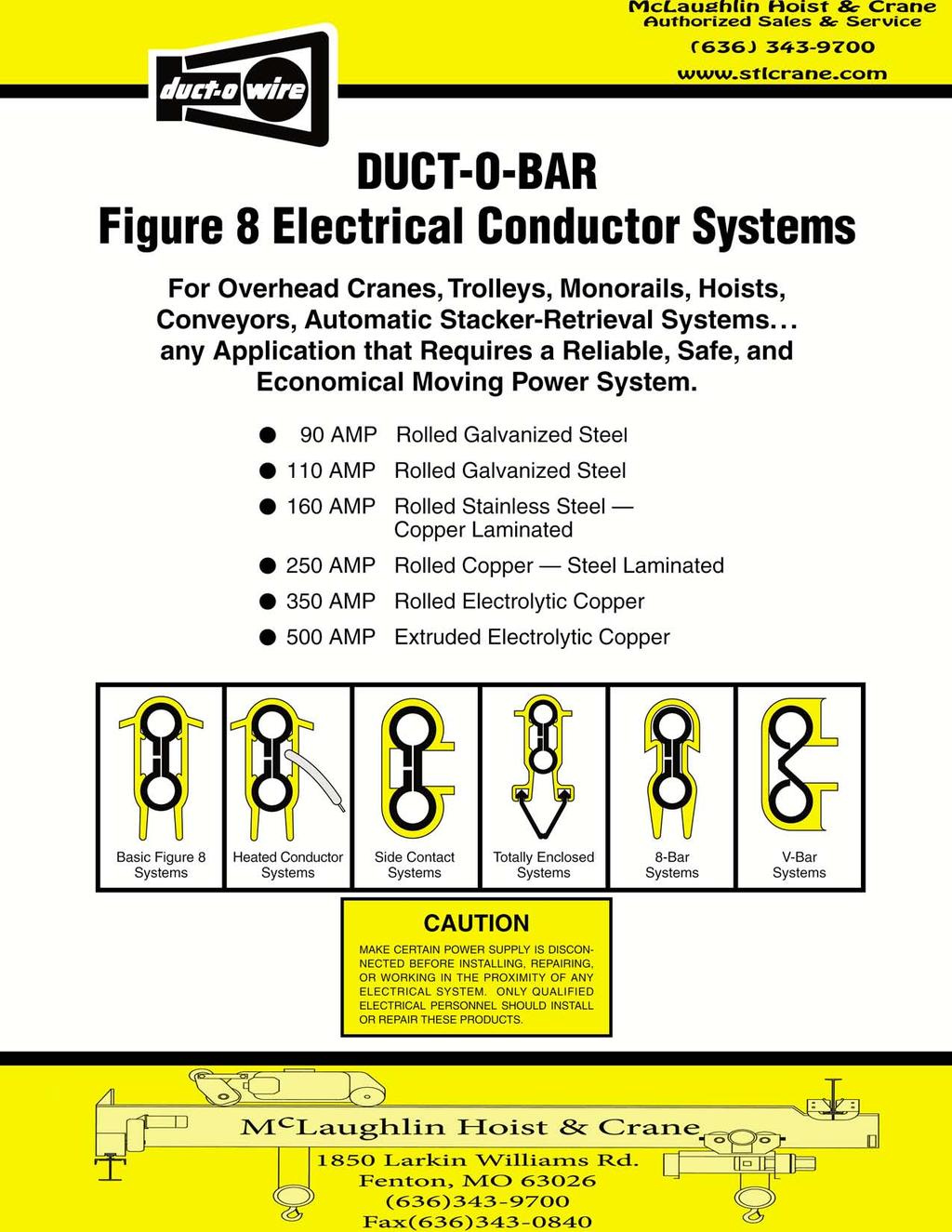
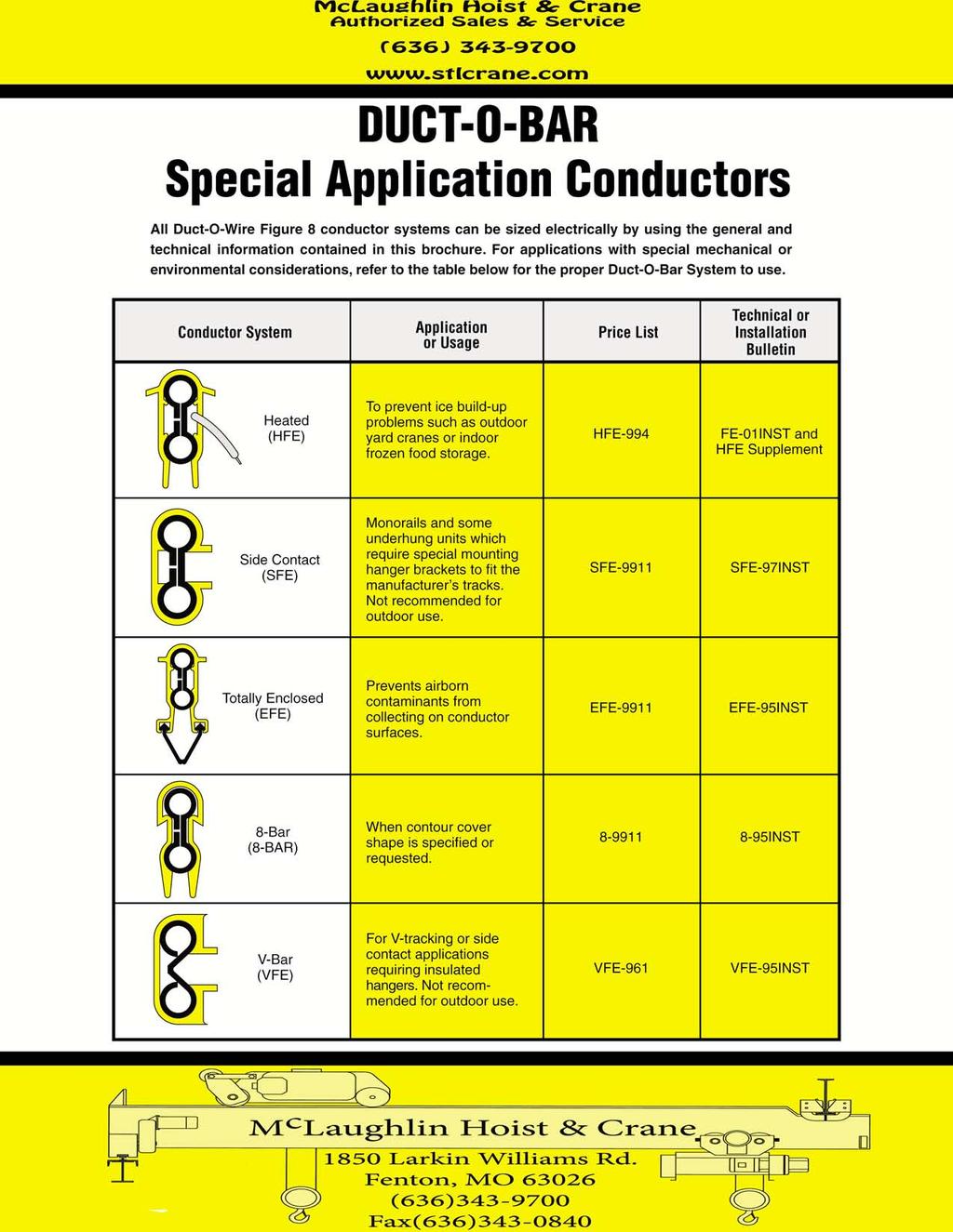
DUCT-O-BAR Figure 8 Electrical Conductor Systems
 DUCT-O-BAR Figure 8 Electrical Conductor Systems For Overhead Cranes, Trolleys, Monorails, Hoists, Conveyors, Automatic Stacker-Retrieval Systems... any Application that Requires a Reliable, Safe, and
DUCT-O-BAR Figure 8 Electrical Conductor Systems
 DUCT-O-BAR Figure 8 Electrical Conductor Systems For Overhead Cranes, Trolleys, Monorails, Hoists, Conveyors, Automatic Stacker-Retrieval Systems... any Application that Requires a Reliable, Safe, and
DUCT-O-BAR HD Series Conductor Systems 500, 1000 & 1500 Ampere Sizes
 DUCT-O-BAR HD Series Conductor Systems 500, 1000 & 1500 Ampere Sizes A high amperage system of heavy duty conductor bars for large cranes and mobile equipment where strength, reliability and safety are
Series T is Ideal for:
 Series T SAF-T-BAR Series T is Ideal for: Light Rail Systems Automated Storage and Retrieval Systems Conveyors Indoor, Dry Locations Small cranes, monorails, hoists Moving cameras and instruments Other
CONDUCTIX Insul-8 Conductor Bar
 CONDUCTIX Insul-8 Conductor Bar CONDUCTIX has designed and built state-of-the-art conductor bar systems for over 60 years. The US branch of Conductix was founded in 1944 as Insul-8 Corporation. Insul-8
Conductor Bar. 8 Bar Side Contact
 Conductor Bar 8 Bar Side Contact Contents Conductor Bar Summary Chart 3 Quick Quote Software 4 Comparison of 8 Bar and Safe-Lec 2 5 Quotations Data Sheet 6-7 Insul 8 8 Bar and Side Contact Overview 8 8
Electromotive Systems ELECTROBAR 8-Bar Conductor Bar System
 Electromotive Systems ELECTROBAR 8-Bar Conductor Bar System ELECTROMOTIVE SYSTEMS ELECTROBAR 8-BAR CONDUCTOR BAR SYSTEMS The practical, proven and economical way to deliver electricity to overhead cranes,
Conductor Bar Hevi-Bar II
 Conductor Bar Hevi-Bar II Contents Hevi-Bar II Overview 3 Conductor Bar Summary Chart 4 Quotations Data Sheet 6-7 Hevi-Bar II Features 8 DURA-COAT Corrosion Protection 8 Typical 4-Bar System 9 Hevi-Bar
POWER BAR SYSTEM ECONOMICAL ENCLOSED CONDUCTOR SYSTEM FOR MOBILE EQUIPMENT M O B I L E E L E C T R I F I C A T I O N
 A e r o B A R POWER BAR SYSTEM ECONOMICAL ENCLOSED CONDUCTOR SYSTEM FOR MOBILE EQUIPMENT M O B I L E E L E C T R I F I C A T I O N AeroBAR Enclosed Conductor Bar System AeroBAR provides many of the advantages
Electromotive Systems ELECTROBAR ELITE Conductor Bar System
 Electromotive Systems ELECTROBAR ELITE Conductor Bar System ELECTROMOTIVE SYSTEMS ELECTROBAR ELITE ENCLOSED CONDUCTOR BAR SYSTEMS Magnetek s Electromotive Systems division proudly offers ELECTROBAR Elite,
Conductor Bar Safe-Lec 2 Hevi-Bar II
 Conductor Bar Safe-Lec 2 Hevi-Bar II Contents Safe-Lec 2 and Hevi-Bar II Overview 3 Conductor Bar Summary Chart 4 Quick Quote Software 5 Quotations Data Sheet 6-7 Safe-Lec 2 8-33 Safe-Lec 2 System Components
Cluster Bar. Conductor Bar Systems. Insul-8 Mobile Electrification. For the Electrification of: Solutions From A Single Source
 Insul-8 Mobile Electrification Cable & Hose Reels Conductor Bar Festoon Pendants Radio Controls Slip Rings Solutions From A Single Source Cluster Bar Conductor Bar Systems For the Electrification of: Cranes
Conductor Bar Safe-Lec 2 Hevi-Bar II
 Conductor Bar Safe-Lec 2 Hevi-Bar II Contents Safe-Lec 2 and Hevi-Bar II Overview 3 Conductor Bar Summary Chart 4 Quick Quote Software 5 Quotations Data Sheet 6-7 Safe-Lec 2 8-33 Safe-Lec 2 System Components
Cable Festoon Systems - For Moving Machinery
 Cable Festoon Systems - For Moving Machinery CONDUCTIX offers a comprehensive range of Cable Festoon Systems to power moving machinery. Our festoon systems are ideal for supporting, protecting, and managing
Conductor Bar Safe-Lec 2 Hevi-Bar II
 Conductor Bar Safe-Lec 2 Hevi-Bar II Contents 2 Safe-Lec 2 and Hevi-Bar II Overview 3 Conductor Bar Summary Chart 4 Quick Quote Software 5 Quotations Data Sheet 6-7 Safe-Lec 2 8-33 Safe-Lec 2 System Components
QuickBridge TM. Modern Overhead Crane Bridge Electrification
 QuickBridge TM Modern Overhead Crane Bridge Electrification Features and Benefits QuickBridge TM is a new concept in bridge electrification to give your overhead cranes a clean, contemporary look. QuickBridge
Cable Festoon Systems - For Moving Machinery
 Cable Festoon Systems - For Moving Machinery CONDUCTIX offers a comprehensive range of Cable Festoon Systems to power moving machinery. Our festoon systems are ideal for supporting, protecting, and managing
Electromotive Systems ELECTROBAR FS Conductor Bar System
 Electromotive Systems ELECTROBAR FS Conductor Bar System ELECTROMOTIVE SYSTEMS ELECTROBAR FS CONDUCTOR BAR SYSTEM Magnetek knows the safety and performance of your overhead material handling system are
Saf-T-Bar Conductor Bar T Series
 Saf-T-Bar Conductor Bar T Series P/N 964001 2012.04.12 Rev. 6 SERIES T SAF-T-BAR CONDUCTOR BAR 1 Conductix Incorporated The technical data and images which appear in this manual are for informational purposes
Cable Festoon Systems. C-Track Stretch Wire Rope
 Cable Festoon Systems C-Track Stretch Wire Rope Contents OVERVIEW 3 Festoon Specification Data Sheets 4-5 "Quick Quote Web" Software 6 C-Track Festoon Configurations 7 Flat Cable and Connectors PVC Flat
Energy Supply Systems
 Energy Supply Systems SINGLE POLE INSULATED CONDUCTOR RAIL 815 100 amps KAT0815-0001b-E Conductor rail system in a high bay storage Slip ring with conductor rail system in a stretch-foil packing machine
Saf-T-Bar Conductor Bar H Series
 Saf-T-Bar Conductor Bar H Series P/N 968801 2012.04.24 Rev. 6 SERIES H SAF-T-BAR CONDUCTOR BAR 1 Conductix Incorporated The technical data and images which appear in this manual are for informational purposes
Magnetek ELECTROBAR FINGER SAFE (FS) Conductor Bar System
 Conductor Bar System") Magnetek ELECTROBAR FINGER SAFE (FS) Conductor Bar System ELECTROMOTIVE SYSTEMS ELECTROBAR FINGER SAFE (FS) CONDUCTOR BAR SYSTEM Magnetek knows the safety and performance of your overhead material handling
Magnetek ELECTROBAR FINGER SAFE (FS) Conductor Bar System ELECTROMOTIVE SYSTEMS ELECTROBAR FINGER SAFE (FS) CONDUCTOR BAR SYSTEM Magnetek knows the safety and performance of your overhead material handling
BUSWAY Low Voltage (Pow-R-Flex)
") BUSWAY LOW VOLTAGE (POW-R-FLEX) PART 1 GENERAL 1.01 1.02 SCOPE The Contractor shall furnish and install the busway system including all necessary fittings, hangers and accessories as specified herein and
BUSWAY LOW VOLTAGE (POW-R-FLEX) PART 1 GENERAL 1.01 1.02 SCOPE The Contractor shall furnish and install the busway system including all necessary fittings, hangers and accessories as specified herein and
Industrial Control Transformers
 6 Industrial Control Transformers Section 6 Industrial Control Transformers provide a low and safe control voltage for the operation of electromagnetic devices, such as motor starters, contactors, solenoids
VAHLE MOTOR POWERED CABLE REELS
 VAHLE MOTOR POWERED CABLE REELS INDEX Page Introduction 2, 3 Cable selection 4 Typical applications 5 Questionnaire 6, 7 Model explanation 8 36 Reel selection charts monospiral wrap, horizontal payout
Type K Features. Heavy, stainless steel terminals. Average 7652 watts per. single unit. Designed to NEMA resistor standards.
 Hubbell Industrial Controls, Inc. Euclid Power Resistors Euclid Power Resistors Type K and Type HHC 38 to 695 Amperes Catalog & Price List January 2011, Replaces May 2010 Engineered for endurance, the
FABA. Standard Components. Conductor Bar System. publication #FABASC-04 1/1/04 Part Number: Copyright 2003 Electromotive Systems
 FABA Conductor Bar System Standard Components publication #FABASC-04 1/1/04 Part Number: 000-2201 Copyright 2003 Electromotive Systems Table of Contents Section IS 100 A - Introduction General Information
Energy Supply Systems
 Energy Supply Systems MULTIPOLE CONDUCTOR RAIL 831 10-125 amps KAT0831-0001b-E 13 pole multipole conductor rail in 33 package distribution centres of the postal service (Post AG) 9 pole multipole conductor
FESTOON & CONDUCTOR SYSTEMS
 FESTOON & CONDUCTOR SYSTEMS Product Page Conductor Bars, Mounts and Accessories - T-Track Festoon Lock N Roll for Wire Rope - C-Rail - T-Track - Page FESTOON & CONDUCTOr SYSTEMS DESIGN & CONSTRUCTION CONDUCTOR
Cable Festoon Systems. C-Track Stretch Wire Rope
 Cable Festoon Systems C-Track Stretch Wire Rope Contents OVERVIEW 3 Festoon Specification Data Sheets 4-5 "Quick Quote Web" Software 6 C-Track Festoon Configurations 7 Flat Cable and Connectors PVC Flat
10 Commercial, Industrial, Agricultural Services
 10 Commercial, Industrial, Agricultural Services This section describes the Power Company requirements for commercial, industrial, and agricultural services. This section covers single phase and three
Multipole Conductor Rail MultiLine Program 0831
 Multipole Conductor Rail MultiLine Program 0831 Contents Description / Technical Data Description....2 Technical Data....3 Conductor Rails Rails complete with pre-mounted Connector...4 Power Feeds....5
4 pole insulated conductor rails UNILIFT-ULA 35A, 50A, 80A, 100A
 2 Table of contents General information... 4 Elements of the conductor rail supply line... 4 Innovative connection method... 5 Technical properties... 6 Construction of the line section... 6 Line section...
ACI Hoist & Crane. Festoon System. 689 S.W. 7th Terrace Dania, FL (954) Fax (954) Toll Free A-HOIST ( )
 Fax (954) Toll Free A-HOIST ( )") ACI Hoist & Crane Festoon System 689 S.W. 7th Terrace Dania, FL 33004 (954) 921-1171 Fax (954) 921-7117 Toll Free 1-888-4-A-HOIST (1-888-424-6478) www.acihoist.com 2 Standard Duty C-Track Index 1. General
ACI Hoist & Crane Festoon System 689 S.W. 7th Terrace Dania, FL 33004 (954) 921-1171 Fax (954) 921-7117 Toll Free 1-888-4-A-HOIST (1-888-424-6478) www.acihoist.com 2 Standard Duty C-Track Index 1. General
Overhead Crane Specification prepared by SVEDA CRANES SPECIFICATION. * (Top/Under) running * (single/double) girder crane
 running * (single/double) girder crane") SPECIFICATION * (Top/Under) running * (single/double) girder crane 1. SCOPE Crane vendor to provide a complete *-ton capacity * running * girder crane 2. REFERENCE DRAWING (Drawing number and description)
SPECIFICATION * (Top/Under) running * (single/double) girder crane 1. SCOPE Crane vendor to provide a complete *-ton capacity * running * girder crane 2. REFERENCE DRAWING (Drawing number and description)
GENERAL INDEX TR60. 6 YELLOW LINE Continuous Conductors. Max 5 Poles. 8 BLUE LINE Pre-Mounted Conductors TR85H5P. YELLOW LINE Continuous Conductors
 2 Automation - Lift - Handling System GENERAL INDEX 2 DESCRIPTION 3 BUSBAR LINE VERSIONS LINE TYPE / AMPERAGE COVERAGE 5 TR60 40 A 50 A 60 A 70 A 100 A 140 A 160 A 200 A 320 A 6 YELLOW LINE Continuous
Electrobar FS Conductor Bar System
 Electrobar FS Conductor Bar System Electromotive Part Number: 005-1066 R12 Copyright 2015 Magnetek Material Handling Table of Contents Chapter 1.0: Danger, Warnings and Cautions... 33 Chapter 2.0: Disconnecting
Shearing, bending, and rolling capabilities are available along with fabricating from hand drawn sketches to engineered drawings.
 Tazgo Machine Inc. is a full service stocking warehouse. Items we stock include carbon, aluminum & stainless steel shapes, angles, beams, flats, hex bar, bar grating, squares, CR rounds in 1018,1045 &
Generator Fire Safety: Generator assemblies should be located outside the building.
 SECTION 33 70 00 - ELECTRICAL DISTRIBUTION PACKAGED GENERATOR ASSEMBLIES Generator Fire Safety: Generator assemblies should be located outside the building. All fuel piping from the outside of the building
SSR Resistor. SSR Resistor. Resistor Rack. K Resistor HUBBELL. Table of Contents. Hubbell Industrial Controls, Inc.
 Hubbell Industrial Controls, Inc. Power Resistors 3000 Catalog 3000 February 1998 Replaces August 1995 SSR Resistor Type Standard Frame Table of Contents Type Specifications... 2 SSR Resistor Type Universal
TA Ta VA CTRL-XFRMR
 3804 South Street 7964-7263, TX Nacogdoches Phone: 936-69-7941 Fax: 936-60-468 TA2437 Ta-2-437 10VA CTRL-XFRMR Acme Electric Catalog Number TA2437 Manufacturer Acme Electric Description Control Transformer,
WORK STATION BRIDGE CRANES
 FREE STANDING WORK STATION BRIDGE CRANES CAPACITIES: SPANS: ENCLOSED TRACKS: PRODUCTIVITY: Up to 4000 lbs Up to 30' Steel, Aluminum & Stainless Steel Average 28% Increase A Class Above... In Productivity.
radial GATES Waterman Industries of Egypt
 radial GATES USES Maintenance of water elevations in canals Increased storage capacity for reservoirs Diversion of water for irrigation Flow control preserving wide, clear waterways Other areas requiring
The 3m long High-Tro-Reel units are installed consecutively along the side of the rail. Recommended for powering auto conveyors and monorails.
 HIGH-TRO-REEL (Non-Tension ) Multi-Lead Indoor Use Insulated Trolleys UL Listed U L The 3m long High-Tro-Reel units are installed consecutively along the side of the rail. Recommended for powering auto
Collectors. Current Collecting Components/Collectors. Collector Designs for all Applications. Many different Collector Interface Materials & Styles
 Collectors Current Collecting Components/Collectors Collector Designs for all Applications Many different Collector Interface Materials & Styles Rigid Conductor Bar Collectors Pick up Wire Collector Designs
CEILING MOUNTED WORK STATION BRIDGE CRANES & MONORAILS
 CEILING MOUNTED WORK STATION BRIDGE CRANES & MONORAILS CAPACITIES: SPANS: ENCLOSED TRACKS: PRODUCTIVITY: Up to lbs Up to 0', Aluminum & Stainless Average 28% increase A Class Above... In Productivity.
FAN ENGINEERING. Application Guide for Selecting AC Motors Capable of Overcoming Fan Inertia ( ) 2
 2") FAN ENGINEERING Information and Recommendations for the Engineer Twin City Fan FE-1800 Application Guide for Selecting AC Motors Capable of Overcoming Fan Inertia Introduction Bringing a fan up to speed
FAN ENGINEERING Information and Recommendations for the Engineer Twin City Fan FE-1800 Application Guide for Selecting AC Motors Capable of Overcoming Fan Inertia Introduction Bringing a fan up to speed
INTEGRID TRACK (120V) SPECIFICATIONS
 SPECIFICATIONS") INTEGRID TRACK (120V) SPECIFICATIONS GENERAL Integrid Track shall be a combination Track and main runner for mech - anically supporting suspended ceiling systems. Integrid Track shall allow fixtures to
INTEGRID TRACK (120V) SPECIFICATIONS GENERAL Integrid Track shall be a combination Track and main runner for mech - anically supporting suspended ceiling systems. Integrid Track shall allow fixtures to
Electrobar Elite. Instruction Manual. Conductor Bar System. ELITE-03A October 2011 Part Number: R3 Copyright 2011 Electromotive Systems
 Electrobar Elite Conductor Bar System Instruction Manual ELITE-03A October 2011 Part Number: 005-1054-R3 Copyright 2011 Electromotive Systems 2011 MAGNETEK All rights reserved. This notice applies to
AEEB AEVB LOW VOLTAGE SERIES Three-Phase Squirrel Cage Induction Motor Conforming to SS530 (Occasional Use) Conforming to IE1
 Conforming to IE1") AEEB AEVB LOW VOLTAGE SERIES Three-Phase Squirrel Cage Induction Motor Conforming to SS530 (Occasional Use) Conforming to IE1 STANDARD AND SPECIFICATION Performance: Meet the requirement of Singapore standard
AEEB AEVB LOW VOLTAGE SERIES Three-Phase Squirrel Cage Induction Motor Conforming to SS530 (Occasional Use) Conforming to IE1 STANDARD AND SPECIFICATION Performance: Meet the requirement of Singapore standard
REELS. Spring & Motor Driven. For LONG CABLE or HOSE Retrieve Applications SERIES SHO SERIES TMR. Monospiral or Random Wrap Spools.
 Spring & Motor Driven REELS SERIES SHO SPRING SERIES TMR MOTOR Monospiral or Random Wrap Spools For LONG CABLE or HOSE Retrieve Applications RET-d Eight Steps to Reliable Production with Gleason SHO/TMR
ECE 325 Electric Energy System Components 6 Three Phase Induction Motors. Instructor: Kai Sun Fall 2016
 ECE 325 Electric Energy System Components 6 Three Phase Induction Motors Instructor: Kai Sun Fall 2016 1 Content (Materials are from Chapters 13-15) Components and basic principles Selection and application
RECESSED TRACK (120V) SPECIFICATIONS
 SPECIFICATIONS") RECESSED TRACK (120V) SPECIFICATIONS GENERAL Recessed track shall be approved by the NEC for flush-mounting into ceiling or any flat surface. Recessed Track shall allow fixtures to be easily focused, switched,
RECESSED TRACK (120V) SPECIFICATIONS GENERAL Recessed track shall be approved by the NEC for flush-mounting into ceiling or any flat surface. Recessed Track shall allow fixtures to be easily focused, switched,
Stearns Heavy Duty Clutches & Brakes... Rugged, Reliable
 Stearns Heavy Duty Clutches & Brakes... Rugged, Reliable Stearns heavy duty clutches and brakes represent over 75 years of design, engineering and on-the-job experience. Stearns products are backed by
RIG-I-FLEX 140 SERIES CURTAIN TRACKS
 RIG-I-FLEX 140 SERIES CURTAIN TRACKS Parts Included 140 RIG-I-FLEX CWANA code CORD OPERATED/MOTORIZED WALK-ALONG 140 (240) 140-R (240-R) 141 (241) 141-R (241-R) 142 (242) 142-R (242-R) STRAIGHT CURVED
Heavy-Duty Conductor Rail CopperHead
 Heavy-Duty Conductor Rail CopperHead Table of Contents CopperHead Conductor Systems 4 Heavy-Duty Conductor Rails...4 Some Advantages of CopperHead Rail Systems...4 Product Pre-Selection...4 Technical
Motor Basics AGSM 325 Motors vs Engines
 Motor Basics AGSM 325 Motors vs Engines Motors convert electrical energy to mechanical energy. Engines convert chemical energy to mechanical energy. 1 Motors Advantages Low Initial Cost - $/Hp Simple &
INSULATED CONDUCTOR SYSTEMS U 20 U 30 U 40
 INSULATED CONDUCTOR SYSTEMS U 20 U 30 U 40 INSULATED CONDUCTORS U 20 U 30 U 40 INDEX U 20 U 30 U 40 Page Page Page Basic description 4 4 4 Selection of conductors 5-10 5-10 5-10 Conductors 11 24 34, 35
Contents Project: Model: Chk d: Date:
 Contents Model DSHU6. DSHU6.7 DSHU6. DSU6. DSHU6. DSU6.7 DSHU6.7 8DSU6. 8DSHU6. 8DSU6.7 8DSHU6.7 DSU6. DSU67. Section Page Specifications -7, 8 Selection Chart -7., 8. Performance Curves -6 Outline Drawings
Series E4F E5F
 Three Phase Induction Motors With Rotors Wound for Hoists Series E4F 160-315 E5F 355-400 ASI NT 003.1 I N D E X Use 2 Electrical Tolerances 9 Mechanical Tolerances 9 General Characteristics 2 Technical
Installation, Operation, & Maintenance Manual
 Installation, Operation, & Maintenance Manual IMPORTANT! DO NOT DESTROY Ceiling Mounted Steel Work Station Bridge Crane and Monorail Gorbel Customer Order No. / Serial No. Gorbel Dealer Date Month Year
General Cable Support Information
 General Cable Support Information Applications Used to support cables in vertical raceways or risers. Relieves the strain that would be placed on terminations, the interior of panels, or other devices
Insulated Conductor Rail SinglePowerLine Program 0812
 Insulated Conductor Rail SinglePowerLine Program 0812 Table of Contents System Description 5 Technical Data 6 General Instructions 7 System Structure 8 Components and their use....8 Insulated Conductor
Dry Type Distribution Transformers
 Selection Steps A. Use the following steps below to manually select a transformer. B. Find the electrical load requirements. These are: 1. Load operating voltage. 2. Load frequency (expressed in Hz). 3.
CABINET - CURRENT TRANSFORMER Indoor - Outdoor 240 Volts Amperes Maximum
 PAGE 1 OF 5 USE: 1. For commercial and industrial installations purchased and installed by the Customer. 2. For use on the following services: 1 phase 3 wire 240 volts, 3 phase 3 wire 240 volts, 3 phase
DRILL CORD. Insulation Nominal Size. Approximate Amps Anixter. Number Number Thickness O.D.
 DRILL CORD Synthetic Rubber Insulation 75 C, 600 Volts For use on drills and other mining equipment. For use on circuits not exceeding 600 volts at a maximum conductor temperature 75 C. 1. CONDUCTOR: Flexible,
Pretest Module 21 Units 1-4 AC Generators & Three-Phase Motors
 Pretest Module 21 Units 1-4 AC Generators & Three-Phase Motors 1. What are the two main parts of a three-phase motor? Stator and Rotor 2. Which part of a three-phase squirrel-cage induction motor is a
Installation Instructions for SINGLE COLOR 24V LINEAR LED NEON
 Installation Instructions for SINGLE COLOR 24V LINEAR LED NEON LLI-N2.9W Prior to installation, please confirm that you have the required system components listed below. LED Neon Flow Extrusions/Lens (Optional)
Installation, Operation, & Maintenance Manual
 Installation, Operation, & Maintenance Manual IMPORTANT! DO NOT DESTROY Free Standing Steel Work Station Bridge Crane Gorbel Customer Order No. / Serial No. Gorbel Dealer Date Month Year This page intentionally
Dearborn Overhead Crane
 A Class Above... In Productivity. In Safety. In Ease of Positioning and Movement. In Ease of Installation. In Designs, Capacities, and Spans. It s no wonder more and more businesses like yours are choosing
Youngstown Power Limit Switches
 Class March, 2012 September, 2008 FRONTLINE AC CRANE CONTROL CLASS 6420 Youngstown Power Limit Switches CONTENTS Description Class Page General Information and Selection...... 2 Application Information.....
Harrington Beam Accessory Kits. Options and Accessories: Consult Factory. Compliance
 Harrington Beam Accessory Kits Provides the convenience of pre-fabricated bracing and bridge beam accessories. For use with any Harrington end truck specify end truck model when ordering. Kit includes:
4 Pole / 5 Pole Enclosed Conductor System
 4 / 5 Pole Conductor System 4 Pole / 5 Pole Enclosed Conductor System Enclosed Conductor system with IP23 Finger proof cellular profile. Available in intensities from 20 Amp 200 Amp Data sheet ref : 10
C. Figure 1. CA-16 Front View Figure 2. CA-16 Rear View
 Figure 1. CA-16 Front View Figure 2. CA-16 Rear View 2 2.1. Restraint Elements Each restraint element consists of an E laminated electromagnet with two primary coils and a secondary coil on its center
Data Bulletin. Ground-Censor Ground-Fault Protection System Type GC Class 931
 Data Bulletin 0931DB0101 July 2001 Cedar Rapids, IA, USA Ground-Censor Ground-Fault Protection System Type GC Class 931 09313063 GT Sensor Shunt Trip of Circuit Interrupter Window Area for Conductors GC
SUGGESTED SPECIFICATIONS Pump Frames NS3 thru OMC5
 SOLIDS-HANDLING WASTEWATER PUMPS Pump Frames NS3 thru OMC5 GENERAL Furnish and install Vertical Closed-Shaft Wet-Pit Pumping Units complete with all accessories and appurtenances as shown in the plans
FRACTIONAL HORSEPOWER MOTORS & ACCESSORIES
 TABLE OF CONTENTS Motor Information Guide Definitions And Abbreviations... page 2 Motor Identification Without A Nameplate What To Look For... page 3 Direct Drive Blower Motors: Two Speed... page 4 Three
EASY CONNECT CRANE KIT Festoon Conductor Systems
 ASSEMBLY INSTRUCTION MANUAL EASY CONNECT CRANE KIT Festoon Conductor Systems October, 2005 Copyright 2005, Yale Lift-Tech, division of Columbus McKinnon Corporation Part No. 117463-05 Mounting Instructions
Transmission Line Support Systems
 Coax Bridge Kit Each Coax Bridge Kit provides rooftop support for coax transmission lines on three PVC sleepers and protects the coax from damage with an long steel cover. The three series of products
Hevi-Bar. Conductor Bar Systems. Insul-8 Mobile Electrification. For the Electrification of. Solutions From A Single Source
 Insul-8 Mobile Electrification Cable & Hose Reels Conductor Bar Festoon Pendants Radio Controls Slip Rings Solutions From A Single Source Hevi-Bar Conductor Bar Systems For the Electrification of Cranes
Installation and Parts Manual for SPANCO PF Series Gantry Cranes
 Manual No. 103-0003 REV. 08/14 Installation and Parts Manual for SPANCO PF Series Gantry Cranes ISO 9001 REGISTERED SPANCO, Inc. 2 INSTALLATION AND PARTS MANUAL FOR PF SERIES GANTRIES TABLE OF CONTENTS
Hazardous Factory Sealed Control Devices
 Hazardous Factory Sealed Control Devices Description Page No. Application/Selection 428, 429 Dimensions 40 Manual Motor Starting Switches & Enclosures EDS Series 440, 44 Pilot Lights EFS Series 45 Pilot
The Reliable Choice. Field Pocket Guide
 The Reliable Choice Field Pocket Guide Allowable Ampacities of STABILOY Brand XHHW-2 and Copper 75 C (167 F) 90 C (194 F) 75 C (167 F) 90 C (194 F) Conductor Size (AWG or kcmil) Types RHW, THHW, THW, THWN,
600 SERIES STANDARD DUTY STRAIGHT TRACK INSTALLATION INSTRUCTIONS
 600 SERIES STANDARD DUTY STRAIGHT TRACK INSTALLATION INSTRUCTIONS PLEASE READ INSTRUCTIONS THOROUGHLY BEFORE BEGINNING. A. BI-PARTING TRAVEL 1. Before raising track into position, determine location of
SECTION OWNER FURNISHED EQUIPMENT
 SECTION 11000 - OWNER FURNISHED EQUIPMENT PART I - GENERAL 1.01 GENERAL: A. The Owner has prepurchased and has or will have on site various pieces of equipment to be installed by the Contractor under this
1' to 10' deep and 1' to 25' deep
 ULTRASONIC ECHO-SCALE TM SCALE: INDICATOR: ECHO-SCALE TM NONE PROVIDED electronic sensors for vessels 1' to 10' deep and 1' to 25' deep INSTALLATION & OPERATION s/n 1-800-893-6723 Fax: 925-686-6713 www.forceflow.com
1 Product Description System Layout Safety Instructions Intended Use Installation... 3
 Order Number 0812xx- Contents 1 Product Description... 2 2 System Layout... 2 3 Safety Instructions... 3 4 Intended Use... 3 5 Installation... 3 5.1 Hanger Clamp... 3 5.2 Cutting of Conductor Rail... 4
S&C Circuit-Switcher Mark VI Outdoor Transmission (69 kv through 138 kv)
") Outdoor Transmission (69 kv through 138 kv) Construction Guide This publication sets forth the data required for the user to design a support structure or pedestals for a Mark VI Circuit-Switcher; the
Outdoor Transmission (69 kv through 138 kv) Construction Guide This publication sets forth the data required for the user to design a support structure or pedestals for a Mark VI Circuit-Switcher; the
TAPE EXTENSOMETER Model CONVEX-D. Roctest Limited, All rights reserved.
 INSTRUCTION MANUAL TAPE EXTENSOMETER Model Roctest Limited, 2013. All rights reserved. This product should be installed and operated only by qualified personnel. Its misuse is potentially dangerous. The
CSDA Best Practice. Hi-Cycle Concrete Cutting Equipment. Effective Date: Oct 1, 2010 Revised Date:
 CSDA Best Practice Title: Hi-Cycle Concrete Cutting Equipment Issue No: CSDA-BP-010 : Oct 1, 2010 Revised : Introduction Hi-cycle/high frequency concrete cutting equipment has become more prevalent in
Electrical Tech Note 106
 Electrical Tech Note 106 Biosystems & Agricultural Engineering Department Michigan State University Master Exam Study Guide and Sample Questions 1 Based on the 2014 NEC, Part 8 of PA 230, PA 407, and the
Step 1: Determining Your Total Load
 Monorail System Step 1: Determining Your Total Load In order to design your system the first thing that must be done is to determine the load that you will be lifting. This load (expressed in pounds) will
4 pole insulated conductor rails ULA 35A, 50A, 80A, 100A
 Table of contents General information... 3 Elements of the conductor rail supply line... 3 Innovative connection method... 3 Technical properties... Construction of the line section... Line section...
SECTION MOTOR CONTROL
 SECTION 26 24 19 MOTOR CONTROL PART 1 - GENERAL 1.1 SECTION INCLUDES A. Manual motor starters B. Magnetic motor starters C. Combination magnetic motor starters D. Solid-state reduced voltage motor starters
VIII. Three-phase Induction Machines (Asynchronous Machines) Induction Machines
 Induction Machines") VIII. Three-phase Induction Machines (Asynchronous Machines) Induction Machines 1 Introduction Three-phase induction motors are the most common and frequently encountered machines in industry simple design,
VIII. Three-phase Induction Machines (Asynchronous Machines) Induction Machines 1 Introduction Three-phase induction motors are the most common and frequently encountered machines in industry simple design,
Solar PV Standard Electrical Plan
 *** Provide this document to the inspector along with ALL system installation instructions *** Project Address: Permit Number: SCOPE: Standard plan for installation of solar PV systems utilizing 2 wire
MOTIV-8 FLEXIBLE CABLE SYSTEMS
 MOTIV-8 FLEXIBLE CABLE SYSTEMS www.conductix.com.au CONDUCTIX FLEXIBLE CABLE SYSTEMS Designed and manufactured in Australia. Proven in applications throughout the world for over 25 years. Full range of
ENTRANCE EQUIPMENT ER D PAGE 1 OF 5
 PAGE 1 OF 5 USE: Requirements for entrance equipment. PREVIOUS REVISION 07-01-98 ORIGINATED 03-94 PREVIOUS NUMBER ER 100 (12-01-81) LATEST REVISION: Updated meter socket labeling specification and instrument
Terminal Blocks. Section 12. Control Catalog 12-1
 CR151K Resilient Modular Terminal Blocks CR151C (top) and CR151A Modular Terminal Blocks DIN-rail Mounted Terminal Blocks (CR151K)...12-2 Product Tables...12-3, 12-4 Accessories...12-3, 12-4 Technical