Cable Festoon Systems - For Moving Machinery
|
|
|
- Martha Bridges
- 5 years ago
- Views:
Transcription
1


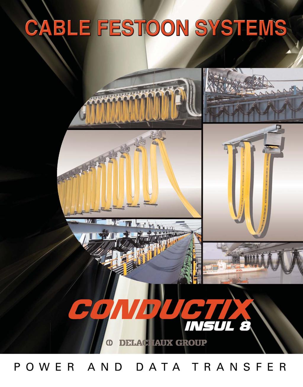
2 Cable Festoon Systems - For Moving Machinery CONDUCTIX offers a comprehensive range of Cable Festoon Systems to power moving machinery. Our festoon systems are ideal for supporting, protecting, and managing power and data cables, or air/fluid hoses. Whatever the particular cable/hose package or running speed, CONDUCTIX has the appropriate system for the job. Primary systems include: Light-duty Stretched Wire Systems Standard and Heavy-Duty C-Track Systems Standard and Heavy-Duty Square Bar Systems Medium Duty I-Beam Systems Heavy-Duty I-Beam Systems - designed for port container cranes and mill duty applications. CONDUCTIX has custom-engineering systems also, so if you don t see what you need, contact us with your requirements. Check out the applications photos on the inside back cover of this catalog. Cable Festoon Systems are available for indoor use, outdoor use, and hazardous or corrosive environments. Our systems are ideal for overhead cranes, gantry cranes, water treatment systems, car wash systems, bulk material conveyors, plating lines, and many other types of moving machines. Choose from a complete range of cable and festoon accessories, including cable connectors, tow cables/webbing, cable organizers, junction boxes, and push-button pendants. (See Pendant & Radio Catalog.) CONDUCTIX Factory-Assembled Festoon Systems 5 important reasons to have CONDUCTIX factory-assemble your festoon system! Systems are assembled by experienced personnel under ideal factory conditions. The festoon arrives unitized - no loose parts to handle. Small systems ship in a carton or crate. Large systems come in a steel shipping frame. Control trolleys (if ordered) are pre-wired to save installation time. Standard C-Track in carton Downtime is minimized and installation time and expenses are greatly reduced. Systems can be quickly transferred from the shipping channel to the machine channel. The problems that can occur during field assembly are greatly reduced. Heavy-Duty C-Track in crate - with control trolley System ready to be transported to job site Heavy-Duty I-Beam Festoon in Shipping Frame Installation on a container crane 2
3 Table of Contents General Information and Pre-Assembled Systems 2 Festoon Specification Checklist & Technical Information 4-6 PVC Flat Cable & Connectors 7 Neoprene Flat Cable & Glands 8 Stretched Wire Rope Systems (load: 10 lbs./20 lbs. speed: 200 fpm.) 9 C-Track Systems Standard Duty (load: 40 lbs. speed: 250 fpm.) Heavy-Duty (load: 80 lbs. speed: 500 fpm.) Square Bar Systems Standard Duty (load: 45 lbs. speed: 250 fpm.) 17 Heavy-Duty (load: 150 lbs. speed: 250 fpm.) 18 Systems 18 Flat Cable Trolleys 19 Round Cable Trolleys 20 Medium-Duty I-Beam Systems Series 200 (load: 55 lbs. speed: 200 fpm.) Flat Cable Trolleys 21 Series 225 (load: 150 lbs. speed: 225 fpm.) Flat Cable Trolleys 22 Series 250 (load: 95 lbs. speed: 250 fpm.) Flat Cable Trolleys 23 Round Cable Trolleys 24 Series 350 (load: 175 lbs. speed: 350 fpm.) Flat Cable Trolleys 25 Round Cable Trolleys 26 Festoon Accessories & Junction Boxes Push Button Pendants and Quick Disconnect Connectors 29 Heavy-Duty I-Beam Systems System Overview Application Information (see checklist on pgs. 4-5) 34 Cable Selection 34 Trolley Selection System Calculations 37 Trolley Construction (260 mm) Saddle (360 mm) Saddle (480 mm) Saddle 41 Auxiliary Saddle 42 Bumper Extensions 43 Running Gear Accessories Tow Rope / Tow Chain Shock Cords Round Cable Organizer 52 Cable Separator 52 About CONDUCTIX 53 Terms & Conditions 54 3
4 Festoon Specification Checklist Request Date: / / Sales Person: Company: Contact: Title: Company Type? Tel: Fax: Application Data Estimated Installation Date: Type of Crane: Operating Speed: fpm Acceleration Rate: CMAA Crane Class*: A B C D E F Duty Cycle: (24/7 etc.) Type of System Req d: Power Control Power & Control: Crane Span: ft. or Active Travel: ft. Loop Depth: ft. or Max. Vertical Space Available: ft. Horizontal Storage Distance: ft. or Storage Space Available: ft. * See pg. 6 for details Environmental Data: Indoors Outdoors Dusty Snow Ice Chemicals: Concentration: Operating Temperature: Min Max Hazardous Location: Class Div Group (Refer to NEC for details) Cable Specifications Hook up Length Needed: Fixed end Mobile end Cable List (Fill out table below or attach schedule) AWG # of Cond. Cable / Insulation Type flat round flat round flat round flat round flat round flat round flat round 4
5 Festoon Specification Checklist Accessories / Options Enclosures Required: Fixed End Mobile End: If yes, NEMA Rating*: Terminals Required: Yes No Quick Disconnect Required: Fixed End Mobile End: Tow Ropes: Yes No Tow Webbing: Yes No For curved systems - please contact the factory Pre-Assembly Requested: Yes No Pre-wiring Requested: Yes No Side To Side Clearance Distance for Festoon System: I-Beam Data (if festoon is mounted on I-Beam) I-Beam Type/Size (if known):size: US European List Beam Dimensions (if beam type / size is not known) After completing form, please fax to
6 Technical Information CMAA Crane Classifications Provided for general information only. Refer to CMAA Section 78-6 for full definitions. Class A (Standby or Infrequent Service): Performs precise lifts at slow speed, with long idle period between lifts. Performs lifts at full or near rated capacity. Power houses, public utilities, turbine rooms. Class B (Light Service): Light service requirements at slow speed. Performs 2 to 5 lifts/hour, light to occasional full loads, at 10 ft. average height. Repair shops, light assembly, service buildings, light warehousing. Class C (Moderate Service): Moderate service requirement with loads averaging 50% of capacity. 5 to 10 lifts per hour at 15 ft. average lift height. Not more that 50% of lifts at rated capacity. Machine shops, paper mill machine rooms, etc. Class D (Heavy Service): Bucket/magnet duty, where heavy duty production is required. Loads of 50% capacity handled constantly. 10 to 20 lifts per hour averaging 15 ft. lift height. Not over 65% of the lifts at rated capacity. Heavy machine shops, foundries, fabricating plants, steel warehouses, container yards, lumber mills, etc. Class E (Severe Service): Loads approaching capacity throughout the life of the crane. 20 or more lifts per hour at or near rated capacity. Magnet/bucket cranes for scrap yards, cement mills, lumber mills, fertilizer plants, container handling. Class F (Continuous Severe Service): Handles loads approaching capacity continuously under severe service conditions throughout the life of the crane. Includes custom designed specialty cranes performing work critical to the total production facility. Needs to have the highest reliability and ease of maintenance. NEMA Enclosure Ratings Provided for general information only. Refer to NEMA Standard 250 and IP AS for full definitions. Note: All enclosures types provide a degree of protection to personnel against incidental contact with the enclosed equipment. NEMA 1 (IP10): Enclosures constructed for indoor use to provide a degree of protection against falling dirt NEMA 2 (IP11): Enclosures constructed for indoor use to provide a degree of protection against falling dirt, and to provide a degree of protection against dripping and light splashing of liquids NEMA 3 (IP54): Enclosures constructed for either indoor or outdoor use to provide a degree of protection against falling dirt, rain, sleet, snow, and windblown dust; and that will be undamaged by external formation of ice on the enclosure NEMA 3R (IP14): Enclosures constructed for either indoor or outdoor use to provide a degree of protection against falling dirt, rain, sleet, and snow; and that will be undamaged by external formation of ice on the enclosure. (Enclosure can be vented.) NEMA 4 (IP56): Enclosures constructed for either indoor or outdoor use to provide a degree of protection against falling dirt, rain, sleet, snow, windblown dust, splashing water, and hose-directed water, and that will be undamaged by the external formation of ice on the enclosure NEMA 4X (IP56): Enclosures constructed for either indoor or outdoor use to provide a degree of protection against falling dirt, rain, sleet, snow, windblown dust, splashing water, hose-directed water, and corrosion; and that will be undamaged by thee external formation of ice on the enclosure NEMA 6 (IP67): Enclosures constructed for either indoor or outdoor use to provide a degree of protection against falling dirt; against hose-directed water, and the entry of water during occasional temporary submersion at a limited depth; and that will be undamaged by the external formation of ice on the enclosure. NEMA 12 (IP52): Enclosures constructed (without knockouts) for indoor use to provide a degree of protection against falling dirt; against circulating dust, lint, fibers, and flying; and against dripping and light splashing of liquids. NEMA 13 (IP54): Enclosures constructed for indoor use to provide a degree of protection against falling dirt; against circulating dust, lint, fibers, and flyings; and against the spraying, splashing, and seepage of water, oil, and noncorrosive coolants. For information on hazardous location specifications, please contact the factory. 6
 Ambient PVC Flat Wire of Conductors Amps* Jacket Cable Short Time Rating Amps** No. of Strands per Conductor Weight per Foot (lbs.) See NEC Table 16.")

7 PVC Flat Cable & Connectors Flat Cable Required cable length = track length plus 10%, plus length required for end connections Cable Part Number Cable Size Continuous Duty Rating at 30 O C Yellow Shielded AWG Number (86 O F) Ambient PVC Flat Wire of Conductors Amps* Jacket Cable Short Time Rating Amps** No. of Strands per Conductor Weight per Foot (lbs.) See NEC Table 16.14(A) Ampacity Correction Factors for temperatures above 30 O C (86 O F) For crane & hoist motors in accordance with article 610 of the 2005 National Electric Code for 90 O C Cables. Black PVC jacket available upon request. All cables from #10 AWG through #16 AWG have rip cords for easy removal of the outer jacket. + Unshielded cable measurements may vary. Contact CONDUCTIX for shielded cable dimensions. Nominal Dimensions Unshielded Cable (Inches)= Size 60 Min. 30 Min Y 4 # x Y 4 # x Y 4 # x Y 4 # x Y 4 # x Y 4 # x Y 4 # x Y 8 # x Y 8 #14 17 Control Cables x Y # x Y #14 17 No Short x Y #16 15 Time Rating x # x.76 Flat Cable Connectors For termination of cable at power source or junction box. Construction: Aluminum Body / Rubber Bushing Catalog No. of Cable Size Ref NPT Number Cables No.of Cond. Wire Size (AWG) Cable # # Y 35838B 1 4 # Y # Y 35835C 1 4 # Y 35835B 1 4 # Y # Y 35837B 1 8 # Y 35837C 1 8 # Y 35837D 1 8 # Y 35838C 1 12 # Y 35838D 1 12 # Y 35838G 2 8 # Y 35837E 2 8 # Y 35837F 2 8 # Y Catalog No. of Cable Size Ref NPT Number Cables No.of Cond. Wire Size (AWG) Cable # 35838E 2 12 # Y 35838F 2 12 # Y 35837G #16 # Y 21815Y 35837H #14 # Y 21815Y 35837J #16 # Y 22542Y 35837K #14 # Y 22542Y 35838H 1 12 # # Y 22542Y 35837L #16 # Y 22994Y 35837M #16 # Y 22994Y Heat Shrinkable Connections For single cable and multiple cable groups, for flat and round cable Corrosion Resistant Flame Retardant Exceeds U.S. Navy requirements for tightness and integrity when used with one flat cable or multiple flat cables on the same size Catalog Cable Knockout Dimension Weight Number Opening Diameter A lbs Dim A 7

8 Neoprene Flat Cables & Connections These cables are for use with festoon systems on cranes, hoists, and any other equipment with lateral transverse motion. They are suitable for indoor or outdoor applications where oil resistance and low-temperature flexing is required. The jacket is Neoprene rated at -40 O C. to 90 O C. and has U.V. inhibitor. The insulation for the awg-size cable is EPR rated at 90 O C. The insulation for the metric-sized cable is Protolon EP. Color Code: 4 conductor cables: green/yellow, black, blue, and brown 8-12 conductors: green/yellow, with all others black with numbers Neoprene Flat Cable - AWG Sizes Size - Awg # of Cond Ampacity at # of Strands 45 O C* per Conductor Thickness (in) Width (in) Wt. #/ft / Neoprene Flat Cable - Metric Sizes Size - mm 2 Ampacity at # of Cond 30 O C* # of Strands Thickness (mm) Width (mm) Wt. Kg/m per Conductor Wt. #/ft *These ampacities are a general guide to conductor size selections. They are not intended to supercede NEC or ICEA ampacity tables. Cable Connector Assemblies These connector assemblies include Neoprene glands. Field cut to match the cable or factory cut before shipment. Call factory for details. Size Wt. # 2 3/4 x 7/ /4 x 1 3/ /2 x 2 3/ /4 8
 MAX. SPEED: 200 FPM MAX.")
9 Stretched Wire Festoon Kits Stretched Wire Rope Festoon Systems are well suited for light duty applications where an intermediate support structure is not available. Economical and dependable, stretched wire rope systems provide electrification to small cranes, moving hoists, and jib cranes. LOAD: 10 LBS (1 WHEEL) MAX. SPEED: 200 FPM MAX. LOAD: 20 LBS (2 WHEEL) MAX. SPEED: 200 FPM MAX. For Flat Cable: Kit Part Number Max. Cable Width Single Wheel 3/4 Max. Double Wheel 1-3/4 Max. Max. Span (In Feet) No. of Trolleys in Kit Kits include all components listed below: Catalog # Component Catalog # Component Nylon Coated Wire Rope, 1/4 Dia Anchor Bracket Hardware Kit Flat Cable Saddle < 3/4 (20mm) wide Tow Bar Flat Cable Clamp Tow Trolley (2 wheel) Trolley (1 wheel) Trolley (2 wheel) For Hose & Round Cable: Kit Part Number Max. No. of Cable / Hose O.D. Span Trolleys 3/16-3/8 Max. 3/8-9/16 Max. 9/16-3/4 Max. (In Feet) in Kit *1 Wheel 2 Wheel *1 Wheel 2 Wheel *1 Wheel 2 Wheel Catalog # Component Catalog # Component Nylon Coated Wire Rope, 1/4 Dia Trolley (2 wheel) shown Hardware Kit Adapter Tow Bar Cable Clip (3/16 to 3/8 ) Anchor Bracket Cable Clip (3/8 to 9/16 ) Tow Trolley (2 wheel) Cable Clip (9/16 to 3/4 ) *Trolley (1 wheel) not shown
10 Standard Duty C-Track Festoon Systems Typical C-Track Festoon Systems (Power & Control) For Overhead Crane Installation Fixed End Junction Box Terminal Strips (inside junction box) Cable Connectors End Clamp Track Hanger Clamp Assembly Intermediate Trolley Cross Arm Support Channels Beam Clamp (for cross arm support channels) C-Track Channel Control Unit Trolley with J-Box; or Quick Disconnect Control Unit Trolley (not shown) Track Joint Assembly Pendant Cable Push-Button Pendant Station Tow Arm Tow Trolley Flat PVC Cable End Stop 10
11 C-Track Festoon Mounting Arrangements To choose festoon components for overhead crane systems, consideration must be given to mounting arrangement. Shown below are four typical arrangements. For all versions, the types and lengths of cable will be needed (track length + 10%, plus hook-up lengths), along with the type of control trolley (J-Box or Quick-Disconnect), and Push Button Pendant, if needed (and type and length of Pendant Cable - see Pendant & Radio Catalog). Box Girder Style Crane - Control and Power Festoon on Opposite Sides To quote this layout, we will need the information above plus: Lengths L1 and L2, if CONDUCTIX is to supply the cross beam support channels Max. loop depth D1 from top of C-Track, and D2 from top of C-Track (or bottom of I-Beam, if I-Beam is used instead of C-Track) Beam size (if I-Beam is used for power festoon) I-Beam Style Crane - Control and Power Festoon on Opposite Sides To quote this layout, we will need the information above plus: Length L, if CONDUCTIX is to supply the cross beam support channels Max. loop depth D1 from top of C-Track and D2 from top of C-Track (or bottom of I-Beam, if I-Beam is used instead of C-Track) Beam size (if I-Beam is used for power festoon) I-Beam Style Crane - Control and Power Festoon on Same Side The size and type of the main beam cap, if one is present To quote this layout, we will need the information above plus: Length L, if CONDUCTIX is to supply the cross beam support channels Max. loop depth D from top of C-Track The size and type of the main beam cap, if one is present I-Beam Style Crane - Control and Power Festoon on Same Side, Welded Cross Support To quote this layout, we will need the information above plus: Length L, if CONDUCTIX is to supply the cross beam support channels Note that cross beam support interfaces with customer supplied bracket welded to underside of main beam Max. loop depth D from top of C-Track 11


 36679_ N/A 1.")


 Low profile track hanger assembly for mounting track to cross arm support (Not Shown) Anchor Clamp - holds channel in place One")
12 Standard Duty C-Track System Components See Pg. 10 for system illustration Galvanized Stainless Wt. # Description 14 Gauge C-Track Channel ft. Section ft. Section Call for curves ft. Section Track Joint Assembly One required for each track section per run, less one. Joint clamp for secure attachment and proper alignment of track sections. Includes four bolts, lock washers, and nuts Optional Welded Joint Assembly for joining track section. Cross Arm Support Channel 36678_ N/A 2.0 / ft. 12 gauge (ordered in 6 increments from 12 to 48 ) 36679_ N/A 1.0 / ft 14 gauge (ordered in 6 increments from 12 to 48 ) Aluminum Beam Clamp for Cross Arm Support Channels N/A.38 Two required for each cross arm support channel N/A N/A.81 Track Hanger Clamp Assembly One required for each cross arm support bracket for each track run. 5 spacing. Designed to be mounted on angle iron brackets with one mounting hole. For mounting track to Cross Arm Support Bracket. Includes all required hardware. (Not Shown) Low profile track hanger assembly for mounting track to cross arm support (Not Shown) Anchor Clamp - holds channel in place One required per track run - includes hardware For use with C-Channel N/A.40 For use with Cross Arm Support Channel (not shown) End Stop One required for power system, two required for control systems with control trolley. Track Support Bracket w/o fastener N/A.28 Allows the removal of single section of C-Track Track Support Bracket N/A.47 With fasteners to mount to Cross Arm Support Track Support Bracket N/A.40 With mounting fasteners 12


 2367 (24 Pin) 5.28 5.59 Control Unit Trolley with Quick Disconnect Lead trolley in control festoon system.")


13 Standard Duty C-Track System Components See Pg. 10 for system illustration Galvanized Stainless Wt. # Description Tow Trolley One required for each piece of moving equipment to be electrified. Plated steel trolley with 2.75 Dia. saddle with cut out for tow bar. Plastic trolley with 2 Dia. plastic saddle with cut out for tow bar. Stainless steel body and saddle with stainless steel sealed wheels and hardware. Tow Bar One required for each tow trolley For mounting on moving equipment 16 long B Control Unit Trolley for J-Box + Two trolleys and one steel saddle mounted on bracket plus fittings to attach control box. ( + Control box not included.) Same as 22203B except with stainless steel body and saddle with stainless steel sealed wheels and hardware. See Page Junction Boxes and Terminals 2366 (16 Pin) 2367 (24 Pin) Control Unit Trolley with Quick Disconnect Lead trolley in control festoon system. Manually pulled with push-button pendant attached to drop cable. Drop cable is then wired into lower half of quick disconnect. Flat festoon cable is wired into upper half of quick disconnect. Zinc plated steel trolleys and hardware. Electrical Ratings: 16A Max. 600 Volts AC. See Pg. 25 for more details. Intermediate Trolley inch trolley with 4 steel shielded ball bearing wheels dia. steel saddle and hardware Stainless steel body and saddle with stainless steel sealed wheels and hardware Intermediate Trolley inch steel trolley with 4 shielded steel ball bearing wheels, 2.75 dia. steel saddle and hardware. 3-inch plastic trolley with 4 shielded steel ball bearing wheels, 2 dia. plastic saddle. (Not Shown) Stainless steel body and saddle with stainless steel sealed wheels and hardware. End Clamp One required for each track run at storage end of track dia. plastic saddle with clamp to secure cable dia. steel saddle with clamp and hardware to secure cable. Stainless steel body and saddle with stainless steel hardware. 13
14 Heavy-Duty C-Track Systems Typical Heavy Duty C-Track Festoon Systems (Power & Control) For Overhead Crane Installation Fixed End Junction Box Terminal Strips (inside junction box) Cable Connectors End Clamp Track Hanger Clamp Assembly Intermediate Trolley Cross Arm Support Channels Beam Clamp (for cross arm support channels) Heavy Duty C-Track Channel Control Unit Trolley with J-Box; or Quick Disconnect Control Unit Trolley (not shown) Track Joint Assembly Pendant Cable Push-Button Pendant Station Tow Arm Tow Trolley Flat PVC Cable End Stop 14


15 Heavy-Duty C-Track System Components See Pg. 14 for system illustration Wt. # Description 12 Gauge C-Track 22302J ft. Section ft. Section Curved sections not available ft. Section See Pg. 12 P/N: For Cross Arm Support Channel Track Joint Assembly One required for each track section per run less one Joint clamp for secure attachment and proper alignment of track sections. Includes four bolts, lock washers and nuts. Track Hanger Clamp Assembly One required for each angle iron bracket for each track run. 10 spacing. Designed to be mounted on angle iron brackets with one mounting hole. Anchor Clamp One required per track run Designed to hold track in place. End Stop One required for each track run at storage end of track. 7.5 End Clamp One required for each track run at storage end of track Aluminum saddle 4 dia. with clamp and hardware to secure cable 5 1/4 wide. 7.5 Cable Trolley Load Rating: 80 lbs. per Trolley High strength aluminum body with 4 dia. aluminum saddle. Trolley bumpers. 7.5 Tow Trolley Load Rating: 80 lbs. per Trolley One required for each piece of moving equipment to be electrified Trolley and aluminum saddle 4 dia. with cut out for tow bar. 15


16 Heavy-Duty C-Track System Components See Pg. 14 for system illustration Wt. # Description 5 Cable Trolley High strength aluminum body and saddle with zinc plated hardware. 5 Tow Trolley High strength aluminum body and saddle with zinc plated hardware. 5 End Clamp Aluminum saddle with clamp & hardware to secure cable. Tow Bar One required for each tow trolley C 2.63 For mounting on moving equipment 24 long. Control Box Trolley Two trolleys and one aluminum saddle 4 dia. mounted on bracket plus, fittings to attach control box. (junction box sold separately below) See Pg. 28 Junction Boxes and Terminal Strips 16
17 Standard Duty Square Bar Components Festoon systems that run on square bar are ideal for very dusty environments. The bar, oriented in a diamond configuration, does not collect dust. Load: 45lb. per trolley Speed: 250 fpm. max. Standard Stainless Wt. # Description Track (Square Bar) ft. Section, Hot-Rolled Steel Track ft. Section, Stainless Steel Track ft. Section, Galvanized Steel Track Call for Curves Track Joint 1.25 Sq Track joint for secure attachment and proper alignment of track sections. Track Hanger Designed to be mounted on angle iron bracket. 5 spacing. Typical, 2.5 spacing in storage area. NOTE: Use Drill Fixture for Drilling Holes. Part #: End Stop Designed to be located between end clamp and intermediate trolley. Tow Trolley Load rating 45 lbs. max. One required per system. 4 long body with cut out for Tow Bar. See Pg. 28 Junction Boxes and Terminal Strips Cable Trolley Trolley load rating 45 lbs. max. 4 long body with 2.75 dia. aluminum saddle. End Clamp One required per system at storage end of track. 17
 24526 46.0 20 ft. Section, Hot Rolled Steel Track 27663 46.0 20 ft. Section, Stainless Steel Track 34603 46.0 20 ft. Section, Galvanized Steel Track Track Joint 1.")

 See Pg.")

18 Heavy Duty Square Bar Components The Heavy Duty Square Bar system is similar to the standard system, but with a heavier bar. Load: 150 lbs. per Trolley. Speed: 250 fpm. max. Standard Stainless Wt. # Description Track (Heavy Square Bar) ft. Section, Hot Rolled Steel Track ft. Section, Stainless Steel Track ft. Section, Galvanized Steel Track Track Joint 1.50 Sq Track joint for secure attachment and proper alignment of track sections. Track Hanger Designed to be mounted on angle iron bracket. 5 spacing. Typical, 2.5 spacing in storage area. Drill Fixture Used for drilling holes at proper locations for attachment of hangers, end clamps and end stops. Control Box Trolley Special Unit. Available upon request Two trolleys and one aluminum saddle 4 dia. mounted on bracket plus fittings to attach control box. (Control box not included) See Pg. 28 Junction Boxes and Terminal Strips Curved Square Bar Systems Curved festoon systems may be required for electrification and/or control of curved monorails and machines that travel in a circular motion. Also, some systems may require more storage space than available. Additional storage space may also be gained by curving the festoon track 90 O to the crane rail. Consult CONDUCTIX for details on curved systems and other solutions for your festoon application. 18

19 Heavy Duty Square Bar Trolleys for Flat Cable Heavy Duty Square Bar Trolleys feature all-steel body construction with aluminum cable saddle. The trolleys are suitable for indoor and outdoor applications for flat cable. Standard wheels are steel with sealed ball bearings. Trolley Body includes Running Gear. SS = stainless steel Load: 150 lbs max. Speed: 250 fpm max. Tow Trolley Cable Trolley End Clamp *S1 *S1 *S1 Body Zinc plated steel, or SS Zinc plated steel, or SS Zinc plated steel, or SS Saddle Aluminum Aluminum Aluminum Main Rollers* 1.77 dia dia. n/a Hardware Zinc plated steel, or SS Zinc plated steel, or SS Zinc plated steel, or SS Cable Pad Neoprene Rubber Neoprene Rubber Neoprene Rubber No. Required per System Saddle One- tow trolley is supplied with towing box for tow bar. Unit Length Cable Window One per cable loop. Zinc Plated One-plus appropriate mounting clamp as determined by factory. *Spark resistant bronze rollers are available for hazardous locations - consult the factory Stainless Steel Dia. Width Width (in.) *S1 Hgt. (In.) Tow Trolley 4 5 1/4 11 1/ Cable Trolley 4 5 1/4 8 5/ End Trolley 4 5 1/4 7 3/ Tow Trolley / B 45413B 13.5 Cable Trolley / B 45440B 11.5 End Trolley / B 45446B 8.5 Tow Trolley 6 5 1/4 12 5/ Cable Trolley 6 5 1/4 10 1/ End Trolley 6 5 1/4 8 7/ Tow Trolley / B 45419B 13.5 Cable Trolley / B 45446B 11.5 End Trolley / B 45472B 8.5 Tow Trolley 8 5 1/4 11 1/ Cable Trolley 8 5 1/4 8 5/ End Trolley 8 5 1/4 7 3/ Tow Trolley / B 45423B 13.5 Cable Trolley / B 45450B 11.5 End Trolley / B 45476B 8.5 *Taller cable window heights are available - contact the factory Wt. # 19
20 Heavy Duty Square Bar Trolleys for Round Cable Heavy Duty Square Bar Trolleys feature all-steel body construction with aluminum cable saddle. The trolleys are suitable for indoor and outdoor applications for round cable. Standard wheels are steel with sealed ball bearings. Trolley Body includes Running Gear. SS = stainless steel Load: 150 lbs max. Speed: 250 fpm max. Tow Trolley Cable Trolley End Clamp *S1 *S1 *S1 Body Zinc plated steel, or SS Zinc plated steel, or SS Zinc plated steel, or SS Saddle Aluminum Aluminum Aluminum Main Rollers* dia dia. n/a Hardware Zinc plated steel, or SS Zinc plated steel, or SS Zinc plated steel, or SS Cable Pad Neoprene rubber Neoprene rubber Neoprene rubber No. Required per System Saddle One - tow trolley is supplied with towing box for tow bar. Unit Length Cable Window One per cable loop. Zinc Plated One - plus appropriate mounting clamp as determined by factory *Spark resistant bronze rollers are available for hazardous locations - consult the factory Stainless Steel Dia. Width Width (in.) *S1 Hgt. (in.) Tow Trolley 4 5 1/4 11 1/ Cable Trolley 4 5 1/4 8 5/ End Trolley 4 5 1/4 7 3/ Tow Trolley / B 45416B 14.0 Cable Trolley / B 45443B 12.0 End Trolley / B 45469B 9.0 Tow Trolley 6 5 1/4 12 5/ Cable Trolley 6 5 1/4 10 1/ End Trolley 6 5 1/4 8 7/ Tow Trolley / B 45421B 14.0 Cable Trolley / B 45448B 12.0 End Trolley / B 45474B 9.0 Tow Trolley 8 5 1/4 11 1/ Cable Trolley 8 5 1/4 8 5/ End Trolley 8 5 1/4 7 3/ Tow Trolley / B 45424B 14.0 Cable Trolley / B 45451B 12.0 End Trolley / B 45477B 9.0 *Taller cable window heights are available - contact the factory Wt. # 20

21 Series 200 I Beam for Flat Cable This I-Beam festoon system is ideal for slow speed operation at speeds up to but not exceeding 200 fpm with loads of up to 55lbs. The Series 200 I Beam System can be strategically used indoors where festoon cable systems are required to operate on an I Beam. These I Beam trolleys are sand cast aluminum with nylon wheels. Load: 55 lbs max. Speed: 200 fpm max. Tow Trolley Cable Trolley End Clamp Nylon Wheels Nylon Wheels w/o Anti-Lift Rollers 24829B 24830B 24828B Steel Wheels Steel Wheels w/o Anti-Lift Rollers 28904B 33530B 24828B Weight in Pounds Description One Tow Trolley required per system. Supplied with towing box for tow bar. Standard construction consists of 5 long body, 2.75 Dia. x 4 wide saddle. Maximum load per trolley is 55 lbs. One End Clamp required per system. Bolted to I Beam with (2) 1/4-20 x.25 mounting bolts. Specifications & Dimensions Body: Sand Cast Aluminum Saddle: 2.75 Dia. Aluminum Wheels: Nylon or Steel Cable Pad: Neoprene Rubber Note: Stainless Steel axle and hardware is available. Call factory for details. Load: 55 lbs. max. per. trolley Speed: 200 fpm. max. Maximum I Beam Flange Width: 4.50 I Beam (customer provided) End Clamp (Fixed) Cable Trolley Tow Webbing Tow Trolley Cable Pigtail for Hookup Festoon Cable 21


22 Series 225 I Beam for Flat Cable The economical Series 225 I Beam Trolleys for flat cable are designed to run on S3 x 5.7#, S3 x 7.5# or S4 x 7.7# I beams only. The saddle is suspended from the trolley by a pivot mechanism which allows the cable package to sway during crane operation providing smoother operation. Lead trolleys are supplied with anti-lift rollers as standard. Load: 150 lbs. max. Speed: 225 fpm. max. Wt. # Description Tow Trolley One required per system. Complete with Anti-Lift Rollers positioned as Lead Trolley in system is equipped with cut out box for engagement of tow bar from mobile consumer. Length = 8.00 Cable Trolley Standard construction consists of steel body, steel saddle. Maximum load per trolley is 150 lbs. Length = 5.50 End Clamp One End Clamp required per system. Positioned at end of system and clamped to I Beam. Length = 7.77 Single Control Trolley Single trolley suitable for mounting junction box. Length = 5.5 Control Box Trolley Two trolleys and one steel saddle mounted on bracket plus fittings to attach control box. Junction box sold separately (See Page 16.) Length = Specifications Body: Low Carbon Steel Saddle: Low Carbon Steel Finish: Zinc Plated w / yellow Dichromate Seal Hardware: Zinc Plated Rollers: Main Dia. Hardened Steel Anti-Lift Dia. Hardened Steel Saddle Diameter: 3.4 Cable Window: 2.38 wide x 1.00 high 22
23 Series 250 I Beam for Flat Cable Series 250 I Beam Trolleys feature zinc plated or stainless steel body and hardware, aluminum saddles with Neoprene pads. These trolleys are suitable for indoor and outdoor applications for flat cable. Note: Order Trolley Body and Running Gear Separately. SS = stainless steel Load: 95 lbs max. Speed: 250 fpm max. Tow Trolley Cable Trolley End Clamp S1-see table S1- see table S1- see table Main Rollers* 1.58 dia. steel flanged 1.58 dia. steel flanged n/a Anti-Lift Rollers (if ordered) 1.38 dia. steel 1.38 dia. steel n/a No. Required per System One - tow trolley is supplied with towing box for tow bar. Anti-lift rollers are req d. One per cable loop. Anti-lift rollers are optional One - plus approximate mounting clamp as determinded by factory *Spark resistant bronze rollers are available for hazardous locations - consult the factory Saddle Unit Length Cable Window Dia. Width Width (in.) *S1 Hgt. (in.) Zinc Plated *Taller cable window heights are available - contact the factory Stainless Steel Tow Trolley 4 5 1/4 11 1/ Cable Trolley 4 5 1/4 8 5/ End Trolley 4 5 1/4 7 3/ Tow Trolley / B 45113B 14.5 Cable Trolley / B 45140B 10.0 End Trolley / B 45166B 8.0 Tow Trolley 6 5 1/4 12 5/ Cable Trolley 6 5 1/4 10 1/ End Trolley 6 5 1/4 8 7/ Tow Trolley / B 45119B 14.5 Cable Trolley / B 45146B 10.0 End Trolley / B 45172B 8.0 Tow Trolley 8 5 1/4 11 1/ Cable Trolley 8 5 1/4 8 5/ End Trolley 8 5 1/4 7 3/ Tow Trolley / B 45123B 14.5 Cable Trolley / B 45150B 10.0 End Trolley / B 45176B 8.0 Wt. # Running Gear for W-Beams Without Anti-Lift Rollers: (SS: ) With Anti-Lift Rollers: (SS: Consult Factory) Beam Code Beam Code W4 x 13 A W6 x 9 D W5 x 16 B W6 x 12 E W5 x 19 C W8 x 10 K Running Gear for S-Beams Without Anti-Lift Rollers: (SS: ) With Anti-Lift Rollers: (SS: ) Beam Code Beam Code S4 x 7.7 C S6 x 12.5 G S4 x 9.5 D S6 x H S5 x 10.0 E S7 x 15.3 J Insert Code Letter to indicate beam size. For other beam sizes consult factory. 23
24 Series 250 I Beam for Round Cable Series 250 I Beam Trolleys feature zinc plated or stainless steel body and hardware, aluminum saddles with Neoprene pads. These trolleys are suitable for indoor and outdoor applications for flat cable. Note: Order Trolley Body and Running Gear Separately. SS = stainless steel Load: 95 lbs max. Speed: 250 fpm max. Tow Trolley Cable Trolley End Clamp *S1-see table *S1-see table *S1-see table Main Rollers* 1.58 dia. steel flanged 1.58 dia. steel flanged n/a Anti-Lift Rollers (if ordered) 1.38 dia. steel 1.38 dia. steel n/a No. Required per System One - tow trolley is supplied with towing box for tow bar. Anti-lift rollers are req d. One per cable loop. Anti-lift rollers are optional One - plus appropriate mounting clamp as determined by factory *Spark resistant bronze rollers are available for hazardous locations - consult the factory Saddle Unit Length Cable Window Dia. Width Width (in.) *S1 Hgt. (in.)* Zinc Plated Stainless Steel Tow Trolley 4 5 1/4 11 1/ Cable Trolley 4 5 1/4 8 5/ End Trolley 4 5 1/4 7 3/ Tow Trolley / B 45116B 15.0 Cable Trolley / B 45143B 10.5 End Trolley / B 45169B 8.5 Tow Trolley 6 5 1/4 12 5/ Cable Trolley 6 5 1/4 10 1/ End Trolley 6 5 1/4 8 7/ Tow Trolley / B 45119B 15.0 Cable Trolley / B 45146B 10.5 End Trolley / B 45172B 8.5 Tow Trolley 8 5 1/4 11 1/ Cable Trolley 8 5 1/4 8 5/ End Trolley 8 5 1/4 7 3/ Tow Trolley / B 45124B 15.0 Cable Trolley / B 45151B 10.5 End Trolley / B 45177B 8.5 *Taller cable window heights are available - contact the factory Wt. # Running Gear for W-Beams Without Anti-Lift Rollers: (SS: ) With Anti-Lift Rollers: (SS: Consult Factory) Beam Code Beam Code W4 x 13 A W6 x 9 D W5 x 16 B W6 x 12 E W5 x 19 C W8 x 10 K Running Gear for S-Beams Without Anti-Lift Rollers: (SS: ) With Anti-Lift Rollers: (SS: ) Beam Code Beam Code S4 x 7.7 C S6 x 12.5 G S4 x 9.5 D S6 x H S5 x 10.0 E S7 x 15.3 J Insert Code Letter to indicate beam size. For other beam sizes consult factory. 24
25 Series 350 I Beam for Flat Cable Series 350 I Beam Trolleys feature zinc plated or stainless steel bodies and hardware, aluminum saddles with Neoprene Pads. 350 Trolleys are suitable for a wide range of demanding applications. The trolleys are suitable for indoor and outdoor applications for flat cable. Note: Order Trolley Body and Running Gear Separately. SS = stainless steel Load: 175 lbs max. Speed: 350 fpm max. Tow Trolley Cable Trolley End Clamp S1-see table S1-see table S1-see table Main Rollers* 2.0 dia. steel 2.0 dia. steel n/a Anti-Lift Rollers 1.38 dia. steel 1.38 dia. steel n/a No. Required per System One - tow trolley is supplied with towing box for tow bar. Anti-lift rollers are req d. One cable per loop. Anti-lift rollers are optional *Spark resistant bronze rollers are available for hazardous locations - consult the factory Saddle Unit Length Cable Window Dia. Width Width (in.) S1 Hgt. (in.)* Zinc Plated One - plus appropriate mounting clamp as determined by factory Stainless Steel Tow Trolley 4 5 1/4 11 1/ Cable Trolley 4 5 1/4 8 5/ End Trolley 4 5 1/4 7 3/ Tow Trolley / B 45113B 16.5 Cable Trolley / B 45140B 12.0 End Trolley / B 45166B 10.0 Tow Trolley 6 5 1/4 12 5/ Cable Trolley 6 5 1/4 10 1/ End Trolley 6 5 1/4 8 7/ Tow Trolley / B 45119B 16.5 Cable Trolley / B 45146B 12.0 End Trolley / B 45172B 10.0 Tow Trolley 8 5 1/4 11 1/ Cable Trolley 8 5 1/4 8 5/ End Trolley 8 5 1/4 7 3/ Tow Trolley / B 45123B 16.5 Cable Trolley / B 45150B 12.0 End Trolley / B 45176B 10.0 Wt. # Running Gear for W-Beams Without Anti-Lift Rollers: (SS: ) With Anti-Lift Rollers: (SS: Consult Factory) Beam Code Beam Code W4 x 13 A W6 x 9 D W5 x 16 B W6 x 12 E W5 x 19 C W8 x 10 K Running Gear for S-Beams Without Anti-Lift Rollers: (SS: ) With Anti-Lift Rollers: (SS: ) Beam Code Beam Code S4 x 7.7 C S6 x 12.5 G S4 x 9.5 D S6 x H S5 x 10.0 E S7 x 15.3 J Insert Code Letter to indicate beam size. For other beam sizes consult factory. 25


26 Series 350 I Beam for Round Cable Series 350 I Beam Trolleys feature zinc plated or stainless steel bodies and hardware, aluminum saddles with Neoprene Pads. 350 Trolleys are suitable for a wide range of demanding applications, such as large cranes and machinery in steel mills and aluminum smelters. The trolleys are suitable for indoor and outdoor applications for round cable. Note: Order Trolley Body and Running Gear Separately. SS = stainless steel Load: 175 lbs max. Speed: 350 fpm max. Tow Trolley Cable Trolley End Clamp S1-see table S1-see table S1-see table Main Rollers* 2.0 dia. steel flanged 2.0 dia. steel flanged n/a Anti-Lift Rollers 1.38 dia. steel 1.38 dia. steel n/a No. Required per Sytem One - tow trolley is supplied with towing box for tow bar. Anti-lift rollers are req d. One per cable loop. Anti-lift rollers are optional *Spark resistant bronze rollers are available for hazardous locations - consult the factory Saddle Unit Length Cable Window Dia. Width Width (in.) S1 Hgt. (in.)* Zinc Plated One - plus appropriate mounting clamp as determined by factory Stainless Steel Tow Trolley 4 5 1/4 11 1/ Cable Trolley 4 5 1/4 8 5/ End Trolley 4 5 1/4 7 3/ Tow Trolley / B 45116B 17.0 Cable Trolley / B 45143B 13.0 End Trolley / B 45169B 11.0 Tow Trolley 6 5 1/4 12 5/ Cable Trolley 6 5 1/4 10 1/ End Trolley 6 5 1/4 8 7/ Tow Trolley / B 45119B 17.0 Cable Trolley / B 45146B 13.0 End Trolley / B 45172B 11.0 Tow Trolley 8 5 1/4 11 1/ Cable Trolley 8 5 1/4 8 5/ End Trolley 8 5 1/4 7 3/ Tow Trolley / B 45124B 17.0 Cable Trolley / B 45151B 13.0 End Trolley / B 45177B 11.0 Wt. # Running Gear for W-Beams Without Anti-Lift Rollers: (SS: ) With Anti-Lift Rollers: (SS: Consult Factory) Beam Code Beam Code W4 x 13 A W6 x 9 D W5 x 16 B W6 x 12 E W5 x 19 C W8 x 10 K Running Gear for S-Beams Without Anti-Lift Rollers: (SS: ) With Anti-Lift Rollers: (SS: ) Beam Code Beam Code S4 x 7.7 C S6 x 12.5 G S4 x 9.5 D S6 x H S5 x 10.0 E S7 x 15.3 J Insert Code Letter to indicate beam size. For other beam sizes consult factory. 26
 Description 44600 4-6.28 Tow Cable 44600B 6-8.40 Optional item used in both High Speed and 44600C 8-10.51 Outdoor applications. Designed for use on: 44600D 10-12.")


27 Festoon Accessories CONDUCTIX offers a complete selection of accessories for your festoon system, including a variety of push-button pendants to maximize the value of your system. Length Nominal Weight (lbs.) Description Tow Cable 44600B Optional item used in both High Speed and 44600C Outdoor applications. Designed for use on: 44600D Heavy Duty C-Track - 8 Trolleys only. Heavy Duty Square Bar 44600E Series I Beam 44600F Series I Beam Tow Webbing As Required.18 lbs. per ft. Optional item used in both high speed and outdoor applications, ideal for systems in spark resistant environments. Ordered by the foot. Designed for use on: Standard Duty C-Track Standard Duty Square Bar 200 Series I Beam 225 Series I Beam Flat Cable Organizer Catalog Dimensions: Inches Number A B up to B to 1.75 Optional item for systems in order to prevent flat cables within the loops from becoming tangled or caught during operation. Designed for use on: 200 Series I Beam 225 Series I Beam 250 Series I Beam 350 Series I Beam Can also be used on other festoon systems depending upon application Round Cable Organizer L1 L2 Catalog D Cable Number Dia. Range L1 L2 Wt (lbs.) Optional item for systems in order to prevent round cables within loops from becoming tangled or caught during operation. Either one or two per loop may be required. W D 40600P Up to Q Up to Designed for use on: 200 Series I Beam 225 Series I Beam 250 Series I Beam 350 Series I Beam Can also be use on other festoon systems depending upon application. 27

28 Control Trolley Junction Boxes and Terminal Strips CONDUCTIX offers several standard junction box / terminal strip combinations for use with Control Box Trolleys (pgs. 13, 16, 18 and 22). If you don t see the junction box you need, please contact the factory. See pg. 29 for Quick Disconnect connectors, which can be used instead of hard-wired junction box. Size (in.) NEMA* Terminal Strips Included Material Weight 10 x 8 x 6 12 None Painted Steel lbs. 10 x 8 x Pole Control, 8 Pole Control Painted Steel lbs. 10 x 8 x Pole Control Painted Steel lbs. 10 x 8 x Pole Control Painted Steel lbs. 10 x 8 x 6 4 None Painted Steel lbs. 10 x 8 x Pole Power, 8 Pole Control Painted Steel 39362B 10.0 lbs. 10 x 8 x Pole Control Painted Steel 39412B 10.0 lbs. 10 x 8 x Pole Control Painted Steel 39413B 10.0 lbs. 10 x 8 x 6 4X None Stainless Steel lbs. 10 x 8 x 6 4X 12 Pole Power, 8 Pole Power Stainless Steel 39362C 9.5 lbs. 10 x 8 x 6 4X 12 Pole Control Stainless Steel 39412C 9.5 lbs. 10 x 8 x 6 4X 24 Pole Control Stainless Steel 39413C 9.5 lbs. 10 x 8 x 6 4X 8 Pole Power Stainless Steel lbs. 12 x 12 x 6 12 None Painted Steel lbs. 12 x 12 x Pole Control Painted Steel lbs. 12 x 12 x Pole Control, 8 Pole Power Painted Steel lbs. 12 x 12 x 6 4 None Painted Steel lbs. 12 x 12 x Pole Control Painted Steel 36412B 14.9 lbs. 12 x 12 x 6 4 As Drilled Painted Steel lbs. 12 x 12 x Pole Control, 8 Pole Power Painted Steel 39388B 14.9 lbs. 12 x 12 x 6 4X None Stainless Steel lbs. 12 x 12 x 6 4X 36 Pole Control Stainless Steel 36412C 13.5 lbs. 12 x 12 x 6 4X 24 Pole Control, 8 Pole Power Stainless Steel 39388C 13.5 lbs. 14 x 12 x 6 12 None Painted Steel lbs. 14 x 12 x Pole Control Painted Steel lbs. 14 x 12 x Pole Painted Steel lbs. 14 x 12 x Pole Control, 8 Pole Power Painted Steel lbs. 14 x 12 x Pole Control, 8 Pole Power Painted Steel lbs. 14 x 12 x 6 4 None Painted Steel lbs. 14 x 12 x Pole Control Painted Steel 35527B 16.9 lbs. 14 x 12 x Pole Control, 8 Pole Power Painted Steel 39394B 16.9 lbs. 14 x 12 x 6 4X None Stainless Steel lbs 14 x 12 x 6 4X 48 Pole Control Stainless Steel 35527C 15.0 lbs 14 x 12 x 6 4X 36 Pole Control, 8 Pole Power Stainless Steel 39394C 15.0 lbs *See pg. 6 for descriptions of NEMA ratings 28


29 Push Button Pendants Push Button Pendants are used in conjunction with hard-wired control festoon systems. CONDUCTIX offers a complete line of Push Button Pendants and Radio Controls. Ask for Pendant & Radio Catalog to get all the details, or download it from our website - Quick Disconnect Pin Connectors In most industrial environments, Push Button Pendants take a lot of abuse. Eventually, they will need to be replaced. When a pendant station has to be replaced, the biggest concerns are always: Equipment downtime Expense Risk of injury to maintenance personnel CONDUCTIX has the solution to reduce all three of these concerns - the Quick Disconnect Pin Connector. Pendants wired with Quick Disconnect Pin Connectors can be replaced in as little as 5 to 10 minutes, versus two hours with a hard-wired pendant. A positive latch mechanism keeps the connector plugged in until you re ready to disconnect the pendant. The quick-disconnect connectors are available in 16 and 24 pin versions. You can use Quick Disconnects with radio controls as well. Then you can switch from radio control to a standard pendant quickly and easily. Contact CONDUCTIX for more information and a quotation on the Quick Disconnect 29


30 Heavy Duty I-Beam Festoons CONDUCTIX Heavy Duty Festoon systems are ideal for rough-duty industrial applications to include: Port Container Cranes and other large gantry cranes Steel mill cranes Foundry cranes Aluminum handling cranes Bulk Material Handling Conveyors These systems run on customer-supplied I-beams and are available in a variety of configurations to manage long and heavy cable packages. Cable Trolleys can be built with one-tier, two-tier, or three tier cable saddles. Systems can be configured to handle speeds of up to 500 feet per minute. For a System Overview, see pgs For Trolley Construction Details, see pg. 38 For Available Accessories, see pgs


31 Heavy Duty I-Beam Festoon There are five basic steps required to layout a Heavy Duty festoon system. Specific information regarding each step can be found on the accompanying pages. Step I: Application Information All pertinent facts regarding the crane, its electrical requirements and duties, are required to properly size the festoon system. You can use the specification checklist on pgs. 4-5 to collect and communicate this information. Step II: Cable Selection and Arrangement In order to satisfy the electrical requirement of the crane, the number, the size of conductors and the type of cable must be determined. Once determined, they must then be arranged in an order that is suitable for the constant work (flexing) required during operation. Step III: Trolley Selection Method to determine a suitable trolley carrier that will not only protect the electrical cables, but also meet the physical demands of the application. Trolley selection is based on the minimum bend diameter of the cable to be festooned. Minimum allowable cable saddle diameter is 10 times the O.D. of the largest cable in the cable package. After determining cable saddle diameter, a saddle width must be specified by determining the maximum width of the cable package. Step IV: System Calculations Required to determine the length of cables and the number of trolleys required to meet the application requirements. Step V: System Accessories Items that may be required in order to enhance the performance of the festoon system. CONDUCTIX Festoon System on a Container Crane Closeup shot of the same crane. 31
32 Heavy Duty Festoon Overview Terms & Definitions BH Beam Height Height of festoon system I-Beam. SD Storage Distance Space required for storage of festoon system end clamp, trolleys and tow trolley. BH SD System Width Maximum unobstructed area in which the system is hung and operates. FHU Must include sufficient area for cable sway during operation. FHU Hook-Up (Fixed End) Amount of cable required for terminations at fixed end of system. Distance is measured from centerline of end clamp support saddle to the power source, and is determined by LD customer. LD Loop Depth Distance from the underside of I-Beam to the bottom of the loop. 5 Minimum Clearance End Clamp Fastened to lower flange of beam at end of system I-Beam. One required per system. Shock Cord Assembly Designed to reduce shock loads transmitted to trolleys during high speed, high acceleration operation. Shock cords are made of elastomeric material. Quantity per loop is dependent on system application. Trolley Bumper Shock absorbing device dampens collisions between trolleys. Designed to allow sufficient deflection without cables on adjacent trolleys coming into hard contact. Thrust Bar Customer supplied and installed, to be welded to underside of I-Beam against the end clamp, to take horizontal impact during operation. Cables System hardware designed to accommodate either flat or round cables. Tow Chain or Tow Rope Towing connection between system end clamp, trolleys and tow trolley, which transmits pulling forces as the system operates. One assembly required per loop constructed of either chain or steel cable. Cable Organizer Designed to contain and organize cables throughout the loop. Prevents cables from tangling during operation. Quantity per loop and positioning are dependent on system application. 32
33 Heavy Duty Festoon Overview BL T AT BLT Beam Length Total length of I-Beam required for the festoon system. AT Active Travel Distance between centerline of the tow trolley tow box when the system is stored and the farthest point the tow trolley will travel when the system is fully extended. MHU Hook-up (Mobile End) Amount of cable required for terminations at the mobile end of system. Distance is measured from centerline of tow trolley support saddle to the moving equipment, and is determined by customer. MHU Festoon systems are designed to provide electrical power and control signals from a fixed source to a moving consumer. This is accomplished by placing the electrical cables on supports (trolleys) which are free to travel in conjunction with the moving consumer. CONDUCTIX Heavy-Duty Festoon system is designed to provide the utmost protection and care for the electric cables which are the lifeblood of the system. This protection equates to longer cable life, lower maintenance costs, and lower overall operating expenses. The layout below depicts a typical festoon system, the key components, terms and definitions. Running Gear Rollers and hardware fastened to tow trolley and trolleys. Designed to carry trolley load. Set to run on specified I-Beam. Cable Clamp Consists of sectionalized, elastic rubber pad held in place by metal retainer designed to secure electrical cables to cable saddle. Trolley Intermediate moving hardware that carries cable support saddle. Trolley length sized to protect cables during operation. Quantity required per system depends on application. Cable Saddle One piece formed steel designed to provide support for full 180 of cable loop draped over them. Tow Trolley (With Rollers) Functions as first moving carrier, connected to moving equipment via outrigger arm (tube) that is located centrally in the rectangular opening. One required per system. Tow Clamp (Without Rollers) Functions as first moving carrier, fastened to moving equipment via outrigger arm (channel iron). 33
34 System Design Step 1: Specification Information Form from pages: 4-5 Step 2: Cable Selection & Arrangement The first step in designing a festoon system begins with the electrical cables - the type size and number of conductors. Either flat or round cables or a combination of the two can be selected. Generally, it is recommended to use either all round or all flat for a system. However, depending on the application and the actual combination, equipment can be selected to accommodate both types. Care should be taken when selecting round cables as some cables are not suited for the constant flexing required. Highly stranded round cables are recommended as they are designed to have the flexibility required to meet the demands of the system. The next step is to prepare a sketch on paper of how the cables are to be arranged on the support saddles. Here are some general guidelines to follow: Flat Cables: 1) Cables should be arranged such that the larger conductor sized cables (power cables) are on top of the stack. (See diagram.) This provides a larger bending radius, as well as improving heat dissipation. Since the top cable also takes more pulling force during operation, the larger conductor placed on top is better suited to handle this force. 2) Cable packages should be arranged with a width to height ratio of 3 or 4 to 1. Tall and narrow cable stacks can be unstable during operation. 3) Cables should be arranged such that a minimum of 50% of each cable surface is under clamp pressure. (See diagram.) POOR BEST Round Cables: 1) Cable diameter variations should be kept to a minimum. Large deviations in diameters makes clamping difficult and they may not remain secure during operation, see diagram. 2) Cables should be arranged in the following order: 1) The two largest cables are placed in the outer most positions of the support saddle. 2) The remaining cables are then arranged between these two cables, taking care to place the heaviest cables near the centerline of the trolley and the lighter cables to the outer positions, see diagram. It is recommended to distribute the cable load evenly as this is important for smooth running and longer bearing life. BEST POOR BEST POOR Combination Flat & Round Cables: Cable should be arranged in the following order: 1) Large round cables placed on the outer most positions of the cable saddle. Flat cables arranged between the round cables. Distribute weight evenly on both saddles. Use round cable organizers. BEST POOR 34
35 System Design Step 3: Trolley Selection Trolley Selection consists of the following steps: 1) selecting the proper body size, 2) selecting the proper style of running gear, and 3) determining the proper main roller size. 1) Body size selection is determined by the cable arrangement prepared earlier, and is based primarily on the diameter of the support saddle. Saddles are designed to provide support for the full 180 loops of cable which are draped over them. This eliminates the stress on the cable at the saddle edges where the cable begins to hang straight. The rules for proper saddle diameter selection are: For Flat Cables: Cable thickness up to.316": Cable thickness up to.500": Cable thickness over.500": Saddle diameter 6.3 x Cable thickness Saddle diameter 8 x Cable thickness Saddle diameter 10 x Cable thickness For Round Cables: Saddle diameter 10 x Largest cable diameter For dimensional information of trolleys, tow trolleys, etc. see pages 12, 13 & 14. 2) The style of running gear to be selected depends on the application. The following are the recommended guidelines: Running Gear Crowned Main Rollers + Horizontal Guide Rollers Crowned Main Rollers + Horizontal Guide Rollers + Anti-Lift Rollers Flanged Main Rollers Flanged Main Rollers + Anti-Lift Rollers Application Indoor operation Moderate speeds, any duty cycle Outdoor operation if no possibility of ice on beam. All speeds and duty cycles Use where side winds/lateral forces could cause trolley to tip. Especially useful on multiple tier trolleys and beams with narrow flanges. Anti-Lift rollers required on all Tow Trolleys. Indoor operation Moderate speeds - any duty cycle Moderate speeds and any duty cycle Use where side winds/lateral forces could cause trolley to tip. Especially useful on multiple tier trolleys and beams with narrow flanges. Anti-Lift rollers required on all Tow Trolleys. See pages 17 thru 20 for running gear part numbers 35
36 System Design Step 3: Trolley Selection (continued) 3) Proper main roller size is based on the mean operating speed of the festoon system, the running time per day and the load per trolley. The following charts will help determine the size (diameter) of the main roller based on these factors. Please note that the standard rollers are made of hardened steel, however for special applications, rollers with polyurethane tires are also available. These are suited for applications where quiet operation is required and minimal wear of the running beam is desired. Hardened Steel Speed Mean Running Time per Day Ft. / Min. M / Min. (Hours) Up to to 8 8 to 16 Over to 4 4 to 8 8 to 16 Over Up to 2 2 to 4 4 to 8 8 to 16 Over Up to 2 2 to 4 4 to 8 8 to 16 Main Roller Diameter Load per Trolley Inches MM Pounds (Kg) (204) 350 (159) 275 (125) 225 (102) 175 (79) (500) 900 (408) 750 (340) 575 (261) 450 (204) Polyurethane Tired Speed Mean Running Time per Day Ft. / Min. M / Min. (Hours) Up to to 8 8 to 16 Over to 4 4 to 8 8 to 16 Over Up to 2 2 to 4 4 to 8 8 to 16 Over Up to 2 2 to 4 4 to 8 8 to 16 Main Roller Diameter Load per Trolley Inches MM Pounds (Kg) (143) 245 (111) 190 (86) 155 (70) 120 (55) (350) 630 (286) 340 (155) 400 (182) 315 (143) Steps: 1) Select system operating speed 2) Follow line to right to the column displaying appropriate running time per day 3) Follow column down to line displaying appropriate load per trolley (approximate load = [loop depth (ft.) x 2] x total cable package weight lbs. / ft.) 4) Follow line to left to determine main roller diameter 36
37 System Design Step 4: System Calculations BLT SD TL TTL 1 AT LD Symbol AT ATL LD Description Active Travel Active Travel per Loop Loop Depth (distance from underside of I-Beam to bottom of loop) Cable Length per Loop CL = 2 x LD Active Travel per Loop ATL = (CL x SF) - TL Number of Loops NL = AT / ATL Total Cable Length TCL = CL x NL Storage Distance SD = (NLxTL) +TTL 1 SD TL TTL1 SF CL TCL NL Storage Distance Trolley Length Tow Trolley Length (measured from bumper to center line of tow box) Cable Sag Factor Cable Required per Loop Total Cable Length (does not include hook-up footages) Number of Loops Required Speed Ft/min (M/min) up to 2.5 (up to 0.76) CABLE SAG FACTOR CHART 2.51 to 4.0 (0.77 to 1.21) LOOP DEPTH -- FT. (M) 4.01 to 6.5 (1.22 to 1.98) 6.5 to 10.5 (1.99 to 3.2) to 16.5 (3.21 to 5.03) to 26 (5.04 to 7.9) (0-32) (32-40) (40-50) (50-63) (63-80) 0.75* (80-100) 0.75* ( ) 0.75* ( ) *Shock cords are recommended. See pages 23 & 24 for details. 37
38 Trolley Construction/Specifications/Features ) Center Plate Material: 3/8" Hot Rolled Steel Finish: Hot Dipped Galvanized 2) Saddle Assembly Material: 12 Gauge Steel Finish: Hot Dipped Galvanized Features: Formed Saddle from single piece of steel, no welds Saddle has rolled flanges with rounded edges, won t cut cables Saddles bolted to center plate with stainless steel fastener Saddles available with either single or double cable clamping bar 3) Running Gear Side Shields: Material: 5/16" Hot Rolled Steel Finish: Hot Dipped Galvanized Features: Bolted to center plate with stainless steel fastener Independently removable Rollers: Material: Hardened Steel Finish: Zinc Plated Bearings: Permanently Sealed, Ball Bearings Feature: Available with polyurethane tires for quiet travel and minimal beam wear 4) Bumper Material: Neoprene Rubber Durometer: ShoreA fastener: Stainless Steel Feature: Large contact surface area 38
39 10 (260 mm) Saddle Diameter Part Number Wc Inches (mm) W Inches (mm) Clamping Bar Trolley Weight Lbs. (Kg) 40500A 6.00 (152) (470) Single 29 (13.2) 40500B (320) (806) Single 39.5 (17.9) 40505A 6.00 (152) (470) Double 33.2 (15.1) 40505B (320) (806) Double 46.7 (21.2) Note: Running Gear is not included. Must be ordered separately. (See pages 17 thru 20.) Part Number Wc Inches (mm) W Inches (mm) Clamping Bar Tow Trolley Weight Lbs. (Kg) 40510A 6.00 (152) (470) Single 32.3 (14.6) 40510B (320) (806) Single 42.8 (19.4) 40515A 6.00 (152) (470) Double 36.5 (16.6) 40515B (320) (806) Double 50 (22.7) Note: Running Gear is not included. Must be ordered separately. (See pages 17 thru 20.) Part Number Wc Inches (mm) W Inches (mm) Clamping Bar Tow Clamp Weight Lbs. (Kg) 40520A 6.00 (152) (470) Single 29 (13.2) 40520B (320) (806) Single 39.5 (17.9) 40525A 6.00 (152) (470) Double 33.2 (15.1) 40525B (320) (806) Double 46.7 (21.2) Part Number Wc Inches (mm) W Inches (mm) Clamping Bar End Clamp Weight Lbs. (Kg) 40530A 6.00 (152) (470) Single 33.1 (15) 40530B (320) (806) Single 43.6 (19.8) 40535A 6.00 (152) (470) Double 37.3 (16.9) 40535B (320) (806) Double 50.8 (23) 39
40 14 (360 mm) Saddle Diameter Trolley Part Number Wc Inches (mm) W Inches (mm) Clamping Bar Weight Lbs. (Kg) 40501A 6.00 (152) (470) Single 37 (16.8) 40501B (320) (806) Single 49.9 (22.6) 40506A 6.00 (152) (470) Double 41.3 (18.7) 40506B (320) (806) Double 57.2 (26) Note: Running Gear is not included. Must be ordered separately. (See pages 17 thru 20.) Tow Trolley Part Number Wc Inches (mm) W Inches (mm) Clamping Bar Weight Lbs. (Kg) 40511A 6.00 (152) (470) Single 40.3 (18.3) 40511B (320) (806) Single 53.2 (24.1) 40516A 6.00 (152) (470) Double 44.5 (20.2) 40516B (320) (806) Double 60.5 (27.5) Note: Running Gear is not included. Must be ordered separately. (See pages 17 thru 20.) Tow Clamp Part Number Wc Inches (mm) W Inches (mm) Clamping Bar Weight Lbs. (Kg) 40521A 6.00 (152) (470) Single 37.9 (17.2) 40521B (320) (806) Single 50.8 (23) 40526A 6.00 (152) (470) Double 42.2 (19.1) 40526B (320) (806) Double 58.1 (26.4) End Clamp Part Number Wc Inches (mm) W Inches (mm) Clamping Bar Weight Lbs. (Kg) 40531A 6.00 (152) (470) Single 43.8 (19.9) 40531B (320) (806) Single 55.1 (25) 40536A 6.00 (152) (470) Double 48 (21.8) 40536B (320) (806) Double 64 (29) 40
41 19 (480 mm) Saddle Diameter Part Number Wc Inches (mm) W Inches (mm) Clamping Bar Trolley Weight Lbs. (Kg) 40502A 6.00 (152) (470) Single 48.8 (22.1) 40502B (320) (806) Single 64.7 (29.4) 40507A 6.00 (152) (470) Double 53.1 (24.1) 40507B (320) (806) Double 71.9 (32.6) Note: Running Gear is not included. Must be ordered separately. (See pages 17 thru 20.) Part Number Wc Inches (mm) W Inches (mm) Clamping Bar Tow Trolley Weight Lbs. (Kg) 40512A 6.00 (152) (470) Single 52.1 (23.6) 40512B (320) (806) Single 68 (30.9) 40517A 6.00 (152) (470) Double 56.3 (25.5) 40517B (320) (806) Double 75.2 (34.1) Note: Running Gear is not included. Must be ordered separately. (See pages 17 thru 20.) Part Number Wc Inches (mm) W Inches (mm) Clamping Bar Tow Clamp Weight Lbs. (Kg) 40522A 6.00 (152) (470) Single 46.4 (21) 40522B (320) (806) Single 62.3 (28.3) 40527A 6.00 (152) (470) Double 50.7 (23) 40527B (320) (806) Double 69.6 (31.6) Part Number Wc Inches (mm) W Inches (mm) Clamping Bar End Clamp Weight Lbs. (Kg) 40532A 6.00 (152) (470) Single 55.6 (25.2) 40532B (320) (806) Single 71.4 (32.4) 40537A 6.00 (152) (470) Double 60 (27.2) 40537B (320) (806) Double 78.7 (35.7) 41
42 Auxiliary Saddle Auxiliary Saddle In certain applications, additional saddles may be required: a) For large cable packages unable to fit on primary saddle or b) To separate power and control cables. One or two additional saddles may be added, depending on the weight limit of the trolley. D1 Wc D2 W Part Number D1 Inches (mm) D2 Inches (mm) Wc Inches (mm) W Inches (mm) Clamping Bar Weight Lbs. (Kg.) A 6.00 (152) (470) Single 22.5 (10.2) B (320) (806) Single 33 (15) 10 ( (260) A 6.00 (152) (470) Double 26.7 (12.1) B (320) (806) Double 40.2 (18.3) A 6.00 (152) (470) Single 28 (12.7) B (320) (806) Single 38.5 (17.5) 14 (360) 10 (260) A 6.00 (152) (470) Double 32.3 (14.6) B (320) (806) Double 45.7 (20.7) A 6.00 (152) (470) Single 28.2 (12.8) B (320) (806) Single 38.6 (17.5) 19 (480) 10 (260) A 6.00 (152) (470) Double 32.3 (14.6) B (320) (806) Double 45.8 (20.8) A 6.00 (152) (470) Single 31 (14.1) B (320) (806) Single 42.4 (19.2) 14 (360) 14 (360) A 6.00 (152) (470) Double 35.3 (16) B (320) (806) Double 51.2 (23.2) A 6.00 (152) (470) Single 33.5 (15.2) B (320) (806) Single 46.4 (21) 19 (480) 10 (260) A 6.00 (152) (470) Double 37.8 (17.1) B (320) (806) Double 53.7 (24.4) A 6.00 (152) (470) Single 43.6 (19.8) B (320) (806) Single 59.4 (27) 19 (480) 19 (480) A 6.00 (152) (470) Double 47.8 (21.7) B (320) (806) Double 66.7 (30.3) Notes: 1) Auxiliary support saddles are normally selected and ordered with initial order. However, they can be ordered separately for installation to existing systems if required. 2) Certain configurations may require bumper extensions, see page 16 for details. 42


43 Bumper Extensions Bumper Extensions In some configurations, multi-tier trolleys must use bumper extensions to ensure cables on adjacent trolleys do not come into hard contact with one another during operation. The chart below indicates which multi-tier trolleys require bumper extensions. END CLAMP TROLLEY TOW TROLLEY SIDE VIEW D 1 D 2 D 3 Bumper Extension/ Saddle Arrangement D1 D2 D3 Mounting / / - D / - D2 D1 D Vertical / Vertical Horizontal / / - D2 D / - D3 D2 D3 D Vertical / / Vertical / - The CONDUCTIX Bumper Extension Kit ( 40576) may be mounted vertically and/or horizontally to add clearance for cables. Each kit consists of one extension and mounting hardware. Order one kit per trolley and one additional kit for the tow trolley or tow clamp. Mounting Orientation Horizontal Vertical 43

 2.5 (62) 4 (100) 2.5 (62) 4 (100) Maximum Load Lbs. (Kg) 450 (204) 1100 (500) 450 (204) 1100 (500) Part Number 40546 40548 40551 40553 Weight Lbs. (Kg) 24.8 (11.2) 36.1 (16.4) 27.3 (12.4) 38.")

44 Running Gear for S Beams Steel Main Rollers, Crowned Running Gear Consists of (4) side shields with appropriate rollers, galvanized steel spacers and stainless steel fastener. Main rollers: hardened steel, zinc plated with permanently sealed precision ball bearings. Horizontal guide and anti-lift rollers: zinc plated, sealed ball bearings. Operating temperatures: -22 O F to 220 O F. Running gear designed for independent side shield removal. With Horizontal Guide Rollers With Horizontal Guide & Anti-Lift Rollers Main Roller Diameter In. (mm) 2.5 (62) 4 (100) 2.5 (62) 4 (100) Maximum Load Lbs. (Kg) 450 (204) 1100 (500) 450 (204) 1100 (500) Part Number Weight Lbs. (Kg) 24.8 (11.2) 36.1 (16.4) 27.3 (12.4) 38.5 (17.5) Steel Main Rollers, Crowned Running Gear Consists of (4) side shields with appropriate rollers, galvanized steel spacers and stainless steel fastener. Main rollers: hardened steel, zinc plated with permanently sealed precision ball bearings. Anti-lift rollers: zinc plated, sealed ball bearings. Operating temperatures: -22 O F to 220 O F. Running gear designed for independent side shield removal. Without Anti-Lift Rollers With Anti-Lift Rollers Main Roller Diameter In. (mm) 2.5 (62) 4 (100) 2.5 (62) 4 (100) Maximum Load Lbs. (Kg) 450 (204) 1100 (500) 450 (204) 1100 (500) Part Number Weight Lbs. (Kg) 24.8 (11.2) 36.1 (16.4) 27.3 (12.4) 38.5 (17.5) 44
45 Running Gear for S Beams Steel Main Rollers, Polyurethane Tire Running Gear Consists of (4) side shields with appropriate rollers, galvanized steel spacers and stainless steel fastener. Main rollers: steel hub, zinc plated with permanently sealed precision ball bearings. Horizontal guide and anti-lift rollers: zinc plated steel with sealed ball bearings. Operating temperatures: -22 O F to 220 O F. Running gear designed for independent side shield removal. With Horizontal Guide Rollers With Horizontal Guide & Anti-Lift Rollers Main Roller Diameter In. (mm) 2.5 (62) 4 (100) 2.5 (62) 4 (100) Maximum Load Lbs. (Kg) 315 (143) 770 (350) 315 (143) 770 (350) Part Number Weight Lbs. (Kg) 23.3 (10.6) 31.3 (14.2) 24.4 (11.1) 33.7 (15.3) Ordering Instructions How To Order Running Gear: Running gear is assembled to the trolleys and tow trolleys at the factory. They are set to the nominal dimension of the I-beam of choice. Choose the appropriate running gear type and roller diameter. Add the corresponding suffix of the beam size to the base running gear number. Example: 40551E = Running gear with 2.5" dia. steel main roller with horizontal guide and anti-lift rollers set for S5x10.0 I-beam. Beam Size S4 x 7.7 S4 x 9.5 S5 x 10.0 S5 x S6 x 12.5 S6 x S7 x 15.3 S7 x 20.0 Part Number Suffix * C * D E F G H J K Beam Size S8 x 18.4 S8 x 23.0 S10 x 25.4 S10 x 35.0 S12 x 31.8 S12 x 35.0 S15 x 42.9 S15 x 50.0 Part Number Suffix L M N P Q R U V * NOTE: Suffix code C & D are not applicable for running gear with 4" dia. Main Roller. 45

 2.5 (62) 4 (100) 2.5 (62) 4 (100) Maximum Load Lbs. (Kg) 450 (204) 1100 (500) 450 (204) 1100 (500) Part Number 40556 40558 40560 40562 Weight Lbs. (Kg) 24.8 (11.2) 36.1 (16.4) 27.3 (12.4) 38.")
46 Running Gear for W Beams Steel Main Rollers, Crowned Running Gear Consists of (4) side shields with appropriate rollers, galvanized steel spacers and stainless steel fastener. Main rollers: hardened steel, zinc plated with permanently sealed precision ball bearings. Horizontal guide and anti-lift rollers: zinc plated, sealed ball bearings. Operating temperatures: -22 O F to 220 O F. Running gear designed for independent side shield removal. With Horizontal Guide Rollers With Horizontal Guide & Anti-Lift Rollers Main Roller Diameter In. (mm) 2.5 (62) 4 (100) 2.5 (62) 4 (100) Maximum Load Lbs. (Kg) 450 (204) 1100 (500) 450 (204) 1100 (500) Part Number Weight Lbs. (Kg) 24.8 (11.2) 36.1 (16.4) 27.3 (12.4) 38.5 (17.5) Steel Main Rollers, Flanged Running Gear Consists of (4) side shields with appropriate rollers, galvanized steel spacers and stainless steel fastener. Main rollers: hardened steel, zinc plated with permanently sealed precision ball bearings. Anti-lift rollers: zinc plated, sealed ball bearings. Operating temperatures: -22 O F to 220 O F. Running gear designed for independent side shield removal. Without Anti-Lift Rollers With Anti-Lift Rollers Main Roller Diameter In. (mm) 2.5 (62) 4 (100) 2.5 (62) 4 (100) Maximum Load Lbs. (Kg) 450 (204) 1100 (500) 450 (204) 1100 (500) Part Number Weight Lbs. (Kg) 23 (10.4) 33.8 (15.3) 24 (10.9) 36.2 (16.4) 46

 2.5 (62) 4 (100) 2.5 (62) 4 (100) Maximum Load Lbs. (Kg) 315 (143) 770 (350) 315 (143) 770 (350) Part Number 40547 40549 40552 40554 Weight Lbs. (Kg) 23.3 (10.6) 31.3 (14.2) 24.4 (11.1) 33.7 (15.")
47 Running Gear for W Beams Steel Main Rollers, Polyurethane Tire Running Gear Consists of (4) side shields with appropriate rollers, galvanized steel spacers and stainless steel fastener. Main rollers: steel hub, zinc plated with permanently sealed precision ball bearings. Horizontal guide and anti-lift rollers: zinc plated steel with sealed ball bearings. Operating temperatures: -22 O F to 220 O F. Running gear designed for independent side shield removal. With Horizontal Guide Rollers With Horizontal Guide & Anti-Lift Rollers Main Roller Diameter In. (mm) 2.5 (62) 4 (100) 2.5 (62) 4 (100) Maximum Load Lbs. (Kg) 315 (143) 770 (350) 315 (143) 770 (350) Part Number Weight Lbs. (Kg) 23.3 (10.6) 31.3 (14.2) 24.4 (11.1) 33.7 (15.3) Ordering Instructions How To Order Running Gear: Running gear is assembled to the trolleys and tow trolleys at the factory. They are set to the nominal dimension of the I-beam of choice. Choose the appropriate running gear type and roller diameter. Add the corresponding suffix of the beam size to the base running gear number. Example: 40560E = Running gear with 2.5" dia. steel main roller with horizontal guide and anti-lift rollers set for W6 x 12 I-beam. Beam Size W4 x 13 W5 x 16 W5 x 19 W6 x 9 W6 x 12 W6 x 16 W8 x 10 W8 x 13 Part Number Suffix A* B C D E G L L Beam Size W8 x 15 W8 x 18 W8 x 21 Part Number Suffix M N P * NOTE: Suffix code C & D are not applicable for running gear with 4" dia. Main Roller. 47
48 Accessories Step 5: Accessories / Tow Rope Assemblies The use of tow rope or tow chain assemblies are recommended for applications where: Travel speed is greater than 150 FPM (45m/min) Acceleration is greater than 1 ft/s 2 (0.3m/s 2 ) ROPE: Vinyl coated 7x19 galvanized steel aircraft cable 1/4" dia. (6mm) Overall diameter 5/16" (8mm) Working load: 2,800 lbs. HARDWARE: Thimble galvanized steel Aluminum ferrule 7/16" galvanized steel shackle w/ roll pin Length Range Feet Meters A-A up to 6.00 up to A-B 6.01 to to A-C 9.01 to to A-D to to A-E to to A-F to to 6.40 Length Range Feet Meters A-G to to A-H to to A-J to to A-K to to A-L to to A-M to to ROPE: Vinyl coated 7x19 galvanized steel aircraft cable 5/16" dia. (8mm) Overall diameter 3/8" (10mm) Working load: 3,900 lbs. HARDWARE: Thimble galvanized steel Aluminum ferrule 7/16" galvanized steel shackle w/ roll pin Length Range Feet Meters B-A up to 6.00 up to B-B 6.01 to to B-C 9.01 to to B-D to to B-E to to B-F to to 6.40 Length Range Feet Meters B-G to to B-H to to B-J to to B-K to to B-L to to B-M to to
49 Accessories Tow Chain Assembly CHAIN: 0.25" Galvanized steel, grade 30 proof coil Working load: 1,250 lbs. Weight: lbs. / ft. Travel speeds less than 150 FPM HARDWARE: 0.43" Galvanized steel shackle with roll-pin Weight: 0.38 lbs. each Length Range Feet Meters C-A up to 6.00 up to C-B 6.01 to to C-C 9.01 to to C-D to to C-E to to C-F to to 6.40 Length Range Feet Meters C-G to to C-H to to C-J to to C-K to to C-L to to C-M to to Length Calculation Tow Rope / Tow Chain Length *TRL = (**ATL ") x 1.05 *TRL = Tow Rope/Tow Chain Length **ATL = Active Travel Per Loop Ordering Instructions How To Order Tow Rope / Tow Chain: Calculate length using the above formula. Using charts on pages 20 & 21, locate the appropriate length range in order to determine the proper part number. When ordering, specify the part number and the calculated length. Example: Calculated tow rope length of feet. 5/16" diameter tow rope assembly has been chosen. To order specify: feet long. 49
50 Accessories Shock Cord Assembly (with Two Ropes or Four Ropes) The use of shock cord assemblies are recommended for applications where: Travel speed is greater than 300 FPM (100m/min). Acceleration is greater than 2 ft/s 2 (0.6m/s 2 ). L Shock Cord Assembly with Two Ropes MATERIAL: Jacket: Cord: Fittings: Hardware: Polypropylene Natural Rubber Steel, Zinc-Plated Stainless Steel Length Range L.62 Dia Feet Meters A-A up to 2.50 up to A-B 2.51 to to A-C 4.51 to to A-D 6.51 to to A-E 8.51 to to A-F to to 3.81 Length Range L.62 Dia Feet Meters A-G to to A-H to to A-J to to A-K to to A-L to to A-M to to 7.47 Shock Cord Assembly with Four Ropes MATERIAL: Jacket: Cord: Fittings: Hardware: Polypropylene Natural Rubber Steel, Zinc-Plated Stainless Steel L Length Range L.62 Dia Feet Meters B-A up to 2.50 up to B-B 2.51 to to B-C 4.51 to to B-D 6.51 to to B-E 8.51 to to B-F to to 3.81 Length Range L.62 Dia Feet Meters B-G to to B-H to to B-J to to B-K to to B-L to to B-M to to
51 Accessories Replacement Shock Cords L dia. 0.5" D I A Length Range Feet Meters A up to 2.50 up to B 2.51 to to C 4.51 to to D 6.51 to to E 8.51 to to F to to 3.81 Length Range Feet Meters G to to H to to J to to K to to L to to M to to " D I A Length Range Feet Meters A up to 2.50 up to B 2.51 to to C 4.51 to to D 6.51 to to E 8.51 to to F to to 3.81 Length Range Feet Meters G to to H to to J to to K to to L to to M to to 7.47 Length Calculation Shock Cord Length *SCL = **TRL x 0.70 Ordering Instructions How To Order Shock Cord: Calculate length using the above formula. Using charts on pages 22 & 23, locate the appropriate length range in order to determine the proper part number. When ordering, specify the part number and the calculated length. Example: *SCL = Shock Cord Length **TRL = Tow Rope/Tow Chain Length Calculated shock cord length of 7.7 feet. 1/2" diameter shock cord assembly has been chosen. To order specify: 7.7 feet long. 51
52 Accessories Round Cable Organizers Recommended for systems in order to prevent the cables within the loops from becoming tangled or caught during operation. Depending on the application, either one or two per loop may be required. Consult factory for further information. L1 W L2 MATERIAL: Clamps: Rods: Hardware: Steel, Zinc-Plated Stainless Steel Stainless Steel D Cable separator (Please see below.) Part D Cable Dia. Range L1 L2 W Weight Number Inches mm Inches mm Inches mm Inches mm Lbs. Kg A up to.75 up to B up to.75 up to C D E F G H J K L M Cable Separators To be used with round cable organizers listed above. If the sum of the diameters of two adjacent cables within the loop is equal to or less than the dimension W, a cable separator must be installed to prevent cables from becoming tangled within the loop. Part Number Ref Organizer Part Number A A & B B C & D C E & F D G & H E J & K F L & M MATERIAL: Plastic 52
 carries on this tradition of innovation and excellence.")


53 About CONDUCTIX YOUR SINGLE SOURCE FOR MOBILE ELECTRIFICATION Since our inception in 1902, Insul-8 Corporation s parent company, Delachaux S.A., has been a leading international presence in the business of providing mobile electrification. As the Delachaux arm in North and South America, Insul-8 Corporation (formerly sister companies Insul-8 and Industrial Electric Reels, Inc. - a.k.a. IER) carries on this tradition of innovation and excellence. Insul-8 and IER became part of the Delachaux Group in 1975 and officially became one company on December 31, Each company has its own rich history. You ll find Insul-8 products in use everywhere from irrigation systems and manufacturing plants in the heartland of the United States to public transportation systems in Malaysia. Industrial Electric Reels, Inc., began in 1924 with the founding of Industrial Electric Works (IEW), an electrical contractor based in Omaha, Nebraska. After World War II, IEW began the manufacture of electric cable reeling equipment and started IER as an operating division in IER s first cable reel, the hand rewind Series 102 PORT-O-REEL, was quickly followed by light-duty spring retractable cable reels. IER pioneered the development of cable reeling devices and slip rings. Soon the business expanded to larger, custom built motor driven reels and custom engineered slip rings. IER s reputation spread as a quality manufacturer of reels running the gamut from small commercial duty reels to large custom built reels for the most demanding applications such as container cranes, stacker/reclaimers and bulk material ship loaders and unloaders. Conductix products can electrify items Insul-8 Corporation has been a pioneer in providing safety-covered metal conductor from small industrial machinery to large systems for the material handling industry since Insul-8 was the first company to amusement park rides and international design and produce a stainless steel capped aluminum conductor and the only public transit systems. manufacturer of such a product for almost 20 years. Today, there are over 20 million meters (nearly 12,500 miles) of Insul-8 contact conductors and tens of thousands of collecting devices throughout the world. Every major port in the United States currently uses Insul-8 s aluminum/stainless steel contact conductors on container cranes due to the dependability of the bar under the most severe conditions. Insul-8 s festoon systems range from the smallest box-track systems to our most rugged Heavy-Duty Festoon. Insul-8 s festoons are known for their safe and efficient operation in which large numbers of conductors can be handled in minimum space. Insul-8 has been in the business of supplying power from stationary sources to mobile systems for 60 years. Insul-8 s cable reels, slip rings, conductor bar, festoon systems, pendants and radio controls are used in a wide variety of applications ranging from material handling and mass transit systems to water treatment plants and performing arts theaters. As it has been for the last 60 years and always will be, conducting business will continue to be our only business. In December 1997, after a nine month endeavor, Insul-8 Corporation became ISO 9001 certified for the design and manufacture of our entire line of mobile electrification products in both of our U.S.A. plants in Omaha, Nebraska, and Harlan, Iowa. cable and hose reels conductor bar systems cable festoon systems slip rings pendant stations radio controls Specifications may change without notice. All products F.O.B. Omaha, NE, or Harlan, IA, unless otherwise specified. 53
54 Terms & Conditions CONDUCTIX INC. The technical data and images which appear in this manual are for informational purposes only. NO WARRANTIES, EXPRESSED OR IMPLIED, INCLUDING WARRANTIES OF MERCHANTABILITY OR FITNESS FOR A PARTICULAR PURPOSE, ARE CREATED BY THE DESCRIPTIONS AND DEPICTIONS OF THE PRODUCTS SHOWN IN IN THIS MANUAL. CONDUCTIX makes no warranty (and assumes no liability) as to the function of equipment or the operation of systems built according to customer design; or of the ability of any of its products to interface, operate or function with any portions of customer systems not provided by CONDUCTIX. Seller agrees to repair or exchange the goods sold hereunder necessitated by reason of defective workmanship, and material discovered and reported to Seller within one year after shipment of such goods to Buyer. Except where the nature of the defect is such that it is appropriate in Seller s judgement to effect repairs on site. Seller s obligation hereunder to remedy defects shall be limited to repairing or replacing (at Seller s option), FOB point of original shipment by Seller, any part returned to Seller at the risk and cost of Buyer. Defective parts replaced by Seller shall become the property of Seller. Seller shall only be obligated to make such repair or replacement of the goods which have been used by Buyer in service recommended by Seller and altered only as authorized by Seller. Seller is not responsible for defects which arise from improper installation, neglect, or improper use or from normal wear and tear. Additionally, Seller s obligation shall be limited by the manufacturer s warranty, (and shall not be further warranted by Seller) for all parts procured from others according to published data, specifications or performance information not designed by or for Seller. Seller further agrees to replace, or at Seller s option to provide a refund of the sales price of any goods that did not conform to applicable specifications or which differ from that agreed to be supplied which non-conformity is discovered and forthwith reported to Seller within thirty (30) days after shipment to Buyer. Seller s obligation to replace or refund the purchase price for non-conforming goods shall arise once Buyer returns such good FOB point of original shipment by Seller at the risk and cost of Buyer. Goods replaced by Seller shall be come property of Seller. There is no guarantee or warranty as to anything made or sold by Seller, or any service performed, except as to title and freedom from encumbrances, and except as herein expressly stated and particularly without limiting the foregoing. There is no guarantee or warranty, express or implied, of merchantability or of fitness for any particular purpose or against claim of infringement or the like. Seller makes no warranty (and assumes no liability) as to function of equipment or operation of systems built to Buyer s design or of the ability of any goods to interface, operate or function with any portions of Buyer s system not provided by Seller. Seller s liability on any claim; whether in contract (including negligence) or otherwise, for any loss or damage arising out of, connected with, or resulting from the manufacture, sale, delivery, resale, repair, replacement or use of any products or, services shall in no case exceed the price paid for the product or services or any part thereof which give rise to the claim. In no event shall Seller be liable for consequential, special, incidental or other damages, nor shall Seller be liable in respect to personal injury or damage to property on the subject matter hereof unless attributable to gross misconduct of Seller, which shall mean an act of omission by Seller demonstrating reckless disregard of the foreseeable consequences thereof. Seller is not responsible for incorrect choice of models or where products are used in excess of their rated and recommended capacities and design functions or under abnormal conditions. Seller assumes no liability for loss of time, damage or injuries to property or persons resulting from the use of Seller s products. Buyer shall hold Seller harmless from all liability, claims, suits and expenses in connection with loss or damage resulting from operation of products or utilization of services, respectively, of Seller and shall defend any suit or action which might arise there from Buyer s name - provided that Seller shall have the right to elect to defend any such suit or action for the account of Buyer. The foregoing shall be the exclusive remedies of the buyer and all persons and entitles claiming through the Buyer. 54


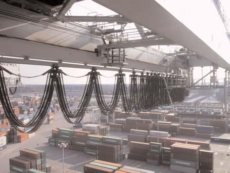

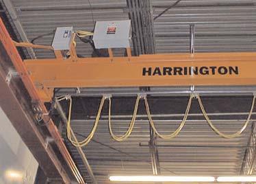

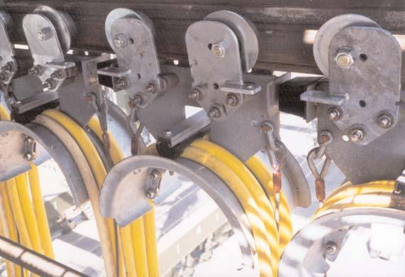
55 Festoon Systems In Action 55
 (0) 2 469 25 60 Fax: +(32) (0) 2 469 29 35 info@conductix.be www.conductix.be GERMANY / AUSTRIA CONDUCTIX GmbH Offenbach / Main Tel: +(49) 69 98 40 23 0 Fax: +(49) 69 98 40 23 99 info@conductix.")
56 CONDUCTIX Worldwide AUSTRALIA CONDUCTIX Pty. Ltd. (Insul-8) Dandenong Tel: +(61) Fax: +(61) info@conductix.com.au BENELUX CONDUCTIX Benelux Brussels Tel: +(32) (0) Fax: +(32) (0) info@conductix.be GERMANY / AUSTRIA CONDUCTIX GmbH Offenbach / Main Tel: +(49) Fax: +(49) info@conductix.de Headquarters DELACHAUX S.A 119 Avenue Louis Roche - BP Gennevilliers Cedex FRANCE Tel: +33 (0) Fax: +33 (0) delachomgt@delachaux.fr CONDUCTIX OPERATIONS 119 Avenue Louis Roche - BP Gennevilliers Cedex FRANCE Tel: +33 (0) Fax: +33 (0) conductix@delachaux.fr CANADA CONDUCTIX Corp. (Insul-8) St Jerome Tel: (450) Fax: (450) infocanada@conductix.us CHINA CONDUCTIX Ltd (Han-Fa) Wuhan Tel: +(86) Fax: +(86) info@conductix.cn FRANCE CONDUCTIX (Delachaux) Belley Tel: +(33) (0) Fax: +(33) (0) infoconductix@conductix.fr Gennevilliers Tel: +(33) (0) Fax: +(33) (0) infoconductix@conductix.fr ITALY CONDUCTIX Srl (Comes) Milan Tel: +39 (0) Fax: +39 (0) Turin Tel: +39 (0) Fax: +39 (0) info@conductix.it MEXICO CONDUCTIX S.de R.L. de C.V. (Insul-8) Monterrey Tel: +(52) Fax: +(52) infomexico@conductix.us UNITED KINGDOM CONDUCTIX Ltd (Insul-8) Salford Tel: +(44) Fax: +(44) info@conductix.co.uk UNITED STATES CONDUCTIX, Inc. (Insul-8) Omaha, NE Tel: +(1) Fax: +(1) info@conductix.us Harlan, IA Tel: + (1) Fax: + (1) info@conductix.us Picture Credit - Cover: c Digital Vision Countries where we are represented: Algeria, Argentina, Austria, Bahrain, Bolivia, Brazil, Bulgaria, Cameroons, Chile, China, Colombia, Congo, Ivory Coast, Croatia, Czechia, Denmark, U.A.S., Ecuador, Egypt, Finland, Gabon, Greece, Guatemala, Guinea, Honduras, Hungary, Indonesia, India, Iraq, Iran, Ireland, Isreal, Japan, Jordania, Korea, Kuwait, Lebanon, Madagascar, Malaisia, Mali, Mauritania, Mexico, Morocco, Netherlands, New Zealand, Niger, Nigeria, Norway, Pakistan, Panama, Paraguay, Peru, Philippines, Poland, Portugal, Romania, Russia, Saudi Arabia,Senegal, Singapore, Slovakia, South Africa, Spain, Sweden, Switzerland, Syria, Thailand, Tunisia, Turkey, Uruguay, Venezuela, Viet-Nam... CAT8100.1
Cable Festoon Systems - For Moving Machinery
 Cable Festoon Systems - For Moving Machinery CONDUCTIX offers a comprehensive range of Cable Festoon Systems to power moving machinery. Our festoon systems are ideal for supporting, protecting, and managing
Cable Festoon Systems. C-Track Stretch Wire Rope
 Cable Festoon Systems C-Track Stretch Wire Rope Contents OVERVIEW 3 Festoon Specification Data Sheets 4-5 "Quick Quote Web" Software 6 C-Track Festoon Configurations 7 Flat Cable and Connectors PVC Flat
Cable Festoon Systems. C-Track Stretch Wire Rope
 Cable Festoon Systems C-Track Stretch Wire Rope Contents OVERVIEW 3 Festoon Specification Data Sheets 4-5 "Quick Quote Web" Software 6 C-Track Festoon Configurations 7 Flat Cable and Connectors PVC Flat
Overhead Crane Specification prepared by SVEDA CRANES SPECIFICATION. * (Top/Under) running * (single/double) girder crane
 running * (single/double) girder crane") SPECIFICATION * (Top/Under) running * (single/double) girder crane 1. SCOPE Crane vendor to provide a complete *-ton capacity * running * girder crane 2. REFERENCE DRAWING (Drawing number and description)
SPECIFICATION * (Top/Under) running * (single/double) girder crane 1. SCOPE Crane vendor to provide a complete *-ton capacity * running * girder crane 2. REFERENCE DRAWING (Drawing number and description)
Features. Track Length System Length Storage Length. Active Travel. System Depth Loop Depth Tow Trolley. Intermediate Trolley
 Magnetek s Electromotive Systems Mill Duty I-Beam Festoon Systems efficiently and economically deliver power and control to cranes used in a variety of severe industrial environments. Features Capacity
ACI Hoist & Crane. Festoon System. 689 S.W. 7th Terrace Dania, FL (954) Fax (954) Toll Free A-HOIST ( )
 Fax (954) Toll Free A-HOIST ( )") ACI Hoist & Crane Festoon System 689 S.W. 7th Terrace Dania, FL 33004 (954) 921-1171 Fax (954) 921-7117 Toll Free 1-888-4-A-HOIST (1-888-424-6478) www.acihoist.com 2 Standard Duty C-Track Index 1. General
ACI Hoist & Crane Festoon System 689 S.W. 7th Terrace Dania, FL 33004 (954) 921-1171 Fax (954) 921-7117 Toll Free 1-888-4-A-HOIST (1-888-424-6478) www.acihoist.com 2 Standard Duty C-Track Index 1. General
MOTIV- 8 FLEXIBLE CABLE SYSTEMS. www. James Crane.com.au PH:
 MOTIV- 8 FLEXIBLE SYSTEMS www. James Crane.com.au PH: 1300 780 420 Email: Robert@jamescrane.com.au CONTENTS System Selection Enquiry Sheet Carrying Capacity kg Recommended Maximum Speed (m/min) Wire Rope
MOTIV-8 FLEXIBLE CABLE SYSTEMS
 MOTIV-8 FLEXIBLE CABLE SYSTEMS www.conductix.com.au CONDUCTIX FLEXIBLE CABLE SYSTEMS Designed and manufactured in Australia. Proven in applications throughout the world for over 25 years. Full range of
recognized as the best in the industry for over 115 years. Each component is designed with greater innovation and manufactured with higher
 0-0_q_K //0 : PM Page C R A N E C O M P O N E N T S TM TM THERE S A CRANE SOURCE COMPONENT FOR EVERY JOB. CraneSource crane bridge components have been recognized as the best in the industry for over years.
C-Rail Festoon track systems
 C-Rail Festoon track systems & Hose carrying systems Application C-Rail festoon track systems are the ideal solution for carrying cables supplying power to many types of moving machinery using either flat
I-Beam Festoon Instruction Manual
 I-Beam Festoon Instruction Manual 7/1/02 Part Number: 125-10030 Copyright 2002 Electromotive Systems 2002 ELECTROMOTIVE SYSTEMS All rights reserved. This notice applies to all copyrighted materials included
QuickBridge TM. Modern Overhead Crane Bridge Electrification
 QuickBridge TM Modern Overhead Crane Bridge Electrification Features and Benefits QuickBridge TM is a new concept in bridge electrification to give your overhead cranes a clean, contemporary look. QuickBridge
Hoists Polipastos Hebezeuge Palans
 Hoists Polipastos Hebezeuge Palans By Detroit Hoist PAGE 2 Better Cranes Begin with Detroit Hoist At the forefront of hoist technology - US made since 1905 For almost a century Detroit Hoist has designed
BUILT WITH INTEGRITY
 WITH INTEGRITY Let us share our wealth of knowledge accumulated over three decades. We have equipped the material handling industry across North America with some of the most resilient cranes and crane
Product Overview Festoon-Systems for I-Beams
 Product Overview Festoon-Systems for I-Beams 2 Conductix-Wampfler Festoon-Systems Count on it! On the go! Cable trolley system program 0350 on a steel mill overhead bridge crane We move your business:
ELECTRONIC OVERHEAD TRAVELLING CRANE DIMENSIONS & LOAD DATA
 ELECTRONIC OVERHEAD TRAVELLING CRANE DIMENSIONS & LOAD DATA FOR ESTIMATING PURPOSES ONLY CONTENTS TOP RUNNING SINGLE GIRDER CRANES 2, 3 & 5 Ton 7.5 & 10 Ton PAGE 2-5 TOP RUNNING DOUBLE GIRDER CRANES 5,
Conductor Bar Safe-Lec 2 Hevi-Bar II
 Conductor Bar Safe-Lec 2 Hevi-Bar II Contents Safe-Lec 2 and Hevi-Bar II Overview 3 Conductor Bar Summary Chart 4 Quick Quote Software 5 Quotations Data Sheet 6-7 Safe-Lec 2 8-33 Safe-Lec 2 System Components
Conductor Bar Hevi-Bar II
 Conductor Bar Hevi-Bar II Contents Hevi-Bar II Overview 3 Conductor Bar Summary Chart 4 Quotations Data Sheet 6-7 Hevi-Bar II Features 8 DURA-COAT Corrosion Protection 8 Typical 4-Bar System 9 Hevi-Bar
SPACEMASTER WIRE ROPE HOISTS
 SPACEMASTER WIRE ROPE HOISTS The Spacemaster SX represents an innovative design that includes a large drum diameter giving Spacemaster SX hoists the lowest headroom and best wheel loads in the industry
SPACEMASTER WIRE ROPE HOISTS
 SPACEMASTER WIRE ROPE HOISTS The Spacemaster SX represents an innovative design that includes a large drum diameter giving Spacemaster SX hoists the lowest headroom and best wheel loads in the industry
Conductor Bar Safe-Lec 2 Hevi-Bar II
 Conductor Bar Safe-Lec 2 Hevi-Bar II Contents 2 Safe-Lec 2 and Hevi-Bar II Overview 3 Conductor Bar Summary Chart 4 Quick Quote Software 5 Quotations Data Sheet 6-7 Safe-Lec 2 8-33 Safe-Lec 2 System Components
600 SERIES STANDARD DUTY STRAIGHT TRACK INSTALLATION INSTRUCTIONS
 600 SERIES STANDARD DUTY STRAIGHT TRACK INSTALLATION INSTRUCTIONS PLEASE READ INSTRUCTIONS THOROUGHLY BEFORE BEGINNING. A. BI-PARTING TRAVEL 1. Before raising track into position, determine location of
Conductor Bar Safe-Lec 2 Hevi-Bar II
 Conductor Bar Safe-Lec 2 Hevi-Bar II Contents Safe-Lec 2 and Hevi-Bar II Overview 3 Conductor Bar Summary Chart 4 Quick Quote Software 5 Quotations Data Sheet 6-7 Safe-Lec 2 8-33 Safe-Lec 2 System Components
Electromotive Systems ELECTROBAR ELITE Conductor Bar System
 Electromotive Systems ELECTROBAR ELITE Conductor Bar System ELECTROMOTIVE SYSTEMS ELECTROBAR ELITE ENCLOSED CONDUCTOR BAR SYSTEMS Magnetek s Electromotive Systems division proudly offers ELECTROBAR Elite,
Beam Master FESTOON SYSTEMS. Container Crane Series I-152 and I-162
 Beam Master FESTOON SYSTEMS Container Crane Series I-152 and I-162 Container Crane Series I-152 and I-162 All the FEATURES required for years of high speed service, even under the most rugged conditions.
W Series Cast Junction Box Options Boxes Available for Raintight, Watertight, or Submersible Applications
 W Series Cast Junction Box Options Boxes Available for Raintight, Watertight, or Submersible Applications This table shows the optional items available on the different types of enclosures shown in this
Product Line Glossary Terms
 PURPOSE This document defines terminology used across all of Harrington s Product Lines. SCOPE These definitions will include the following Product Lines: Manual Electric Air Wire Rope Cranes BACKGROUND
HSpecialties Inc. TABLE OF CONTENTS
 TABLE OF CONTENTS Introduction... Curtain Track Selection Guide...2 Ordering COMPLETE Tracks...3 00 Series Standard-Duty Straight Track...4 200 Series Black Medium-Duty Straight Track...8 300 Series Standard-Duty
Energy Supply Systems
 Energy Supply Systems MULTIPOLE CONDUCTOR RAIL 831 10-125 amps KAT0831-0001b-E 13 pole multipole conductor rail in 33 package distribution centres of the postal service (Post AG) 9 pole multipole conductor
Conductor Bar. 8 Bar Side Contact
 Conductor Bar 8 Bar Side Contact Contents Conductor Bar Summary Chart 3 Quick Quote Software 4 Comparison of 8 Bar and Safe-Lec 2 5 Quotations Data Sheet 6-7 Insul 8 8 Bar and Side Contact Overview 8 8
WORK STATION BRIDGE CRANES
 FREE STANDING WORK STATION BRIDGE CRANES CAPACITIES: SPANS: ENCLOSED TRACKS: PRODUCTIVITY: Up to 4000 lbs Up to 30' Steel, Aluminum & Stainless Steel Average 28% Increase A Class Above... In Productivity.
Energy Supply Systems C-RAIL PROGRAM. KAT a-USA
 Energy Supply Systems C-RAIL PROGRAM 230 KAT0230-0001a-USA C-Rails and Accessories C-Rails Catalog No. Length l Thickness s [mm] [mm] 023200-6M 6000 023200-4M 4000 023201-6M 6000 023201-4M 4000 2 1.5 6,,
DUCT-O-BAR HD Series Conductor Systems 500, 1000 & 1500 Ampere Sizes
 DUCT-O-BAR HD Series Conductor Systems 500, 1000 & 1500 Ampere Sizes A high amperage system of heavy duty conductor bars for large cranes and mobile equipment where strength, reliability and safety are
Specialties Inc. DISCLAIMER TABLE OF CONTENTS
 TABLE OF CONTENTS Curtain Track Selection Guide...2 Ordering COMPLETE Tracks...3 Recommended Track Hanger Spacing...4 100 Series Standard-Duty Straight Track...6 200 Series Black Medium-Duty Straight Track...10
Product Overview I-Beam Festoon Systems
 Product Overview I-Beam Festoon Systems Count on it! On the go! Program 0350 cable trolley system on a steel mill overhead bridge crane We move your business: where ever materials are being handled, you
Under Running, Single Girder Overhead Cranes
 TOTAL CRANE SYSTEMS MANUFACTURERS OF OVERHEAD CRANES AND HOISTS Under Running, Single Girder Overhead Cranes Engineering & Design Data TOTAL CRANE SYSTEMS Crane Reference Diagram All data may be referenced
Dearborn Overhead Crane
 A Class Above... In Productivity. In Safety. In Ease of Positioning and Movement. In Ease of Installation. In Designs, Capacities, and Spans. It s no wonder more and more businesses like yours are choosing
RH Electric Wire Rope Hoists
 RH Electric Wire Rope Hoists Harrington RH wire rope hoists are designed and built for today s heavy-duty wire rope hoist applications including fabricating, die handling, paper mill and production line
Design standards used : CMAA, CSA, AIST, AISE, OSHA, FEM, HMI, CWB, AWS, ANSI, ASME, ASTM, AGMA, NEC, NEMA, IEEE, UL, ISO
 Through innovation and cutting-edge technology, provide sound engineering solutions while improving equipment efficiency, reliability, and safety. Achieve the highest level of customer satisfaction throughout
Multipole Conductor Rail MultiLine Program 0831
 Multipole Conductor Rail MultiLine Program 0831 Contents Description / Technical Data Description....2 Technical Data....3 Conductor Rails Rails complete with pre-mounted Connector...4 Power Feeds....5
ETA-5 RAIL SYSTEMS. , Unified Industries, Inc. All Rights Reserved.
 RAIL SYSTEMS PAGE 1 TABLE OF CONTENTS PAGE Rail Profiles...2-4 Rail Load Charts...5-6 ETA-4 & Hangers...7-10 Inspection Gate...11 ETA-4 & Load Trolleys...12-15 ETA-4 & Festoon Trolley...16-19 ETA-4 &
Cam-Lok Single Pole Connectivity. The industry standard for reliable service under the most severe operating conditions.
 Cam-Lok Single Pole Connectivity The industry standard for reliable service under the most severe operating conditions. Cam-Lok Single Pole Connectivity Cam-Lok connectors are the industry standard Cam-Lok
E L E C T R I C WIRE ROPE H O I S T S
 E L E C T R I C WIRE ROPE H O I S T S RH Electric Wire Rope Hoists Harrington RH wire rope hoists are designed and built for today s heavy-duty wire rope hoist applications including fabricating, die handling,
CONDUCTIX Insul-8 Conductor Bar
 CONDUCTIX Insul-8 Conductor Bar CONDUCTIX has designed and built state-of-the-art conductor bar systems for over 60 years. The US branch of Conductix was founded in 1944 as Insul-8 Corporation. Insul-8
CEILING MOUNTED WORK STATION STEEL BRIDGE CRANE
 SECTION 14636 CEILING MOUNTED WORK STATION STEEL BRIDGE CRANE ***** Gorbel, Inc. manufactures a broad range of material handling cranes including monorail, bridge, gantry, and jib cranes. Numerous work
CABLE GRIPS Strain-Relief Grips Pulling Grips Support Grips
 Tough and dependable, Woodhead cable grips and cord grip bodies are reliable workhorses in any plant environment. They serve as flexible holding devices used to pull cable, rope, or tubing into place,
Electromotive Systems ELECTROBAR 8-Bar Conductor Bar System
 Electromotive Systems ELECTROBAR 8-Bar Conductor Bar System ELECTROMOTIVE SYSTEMS ELECTROBAR 8-BAR CONDUCTOR BAR SYSTEMS The practical, proven and economical way to deliver electricity to overhead cranes,
300 SERIES STANDARD DUTY CURVED TRACK
 300 SERIES STANDARD DUTY CURVED TRACK COMPLETE TRACK MODEL NUMBERS 301A 301W 316A 316W 328A 328W 300B SERIES BLACK CURVED TRACK COMPLETE TRACK MODEL NUMBERS 301AB 301WB 316AB 316WB 328AB 328WB SINGLE CARRIER
GE 8000-Line Motor Control Centers
 GE 8000-Line -1 ENCLOSURE TYPES TYPE 1 General Purpose, Indoor Intended for use indoors, primarily to prevent accidental contact of personnel with the enclosed equipment, in areas where unusual service
4 pole insulated conductor rails UNILIFT-ULA 35A, 50A, 80A, 100A
 2 Table of contents General information... 4 Elements of the conductor rail supply line... 4 Innovative connection method... 5 Technical properties... 6 Construction of the line section... 6 Line section...
Spacemaster. Electric Wire Rope Hoists. 1/2-80 Ton (500-80,000 kg) Innovation... Performance... Reliability.
 Innovation... Performance... Reliability.") Spacemaster SX Electric Wire Rope Hoists Innovation... Performance... Reliability www.rmhoist.com 1/2-80 Ton (500-80,000 kg) Spacemaster SX hoists: The Spacemaster SX represents a revolutionary new generation
Spacemaster SX Electric Wire Rope Hoists Innovation... Performance... Reliability www.rmhoist.com 1/2-80 Ton (500-80,000 kg) Spacemaster SX hoists: The Spacemaster SX represents a revolutionary new generation
Hubbell Workplace Solutions
 Workplace Solutions Hubbell Workplace Solutions - Material Handling & Electrical Products - Festoon Trolleys Adjustable S-Beam Trolleys Our S-Beam Trolleys are designed with your applications in mind.
Conductor Bar Selection
 U L LISTED File # E29805 Contr. 678L Approved in Canada Conductor Bar Selection Determining Ampere Load The conductor selected must be large enough to carry the necessary ampere load safely without undue
Seismic Sensor Accessories SA, SV & ST 6000 Series
 Seismic Sensor Accessories SA, SV & ST 6000 Series Part Number Name Used With Description Housing Material 7295-002 Accelerometer EP Housing SA6200A-X0X; SV6300A-001 Physical protection and access to 1/4-28
Festoon Manual Standard Duty C-Track
 Festoon Manual Standard Duty C-Track 966301.4 Standard Duty C-Track Manual CONDUCTIX INCORPORATED The technical data and images which appear in this manual are for informational purposes only. NO WARRANTIES,
KRANE-KING Jib & Gantry Cranes Gantries Free Standing Jibs Tension & Cantilevered Jibs Hoists
 KRANE-KING Jib & Gantry Cranes Gantries Pages H.4 - H.17 Free Standing Jibs Pages H.18 - H.30 Tension & Cantilevered Jibs Pages H.31 - H.35 Hoists Pages H.36 - H.42 Index to Krane-King Jib & Gantry Cranes
Big performance in a small package
 Series usible & Non-fusible 100 400A Suitable as a Service Entrance ing Means TIP! Manual Switching Devices: Control, oad or usible Which is Best or Your Application? Application Data Typical Control Switch
Interlocks 200 Series
 rd 12070 43 St. NE, St. Michael, MN 55376 763-497-7000 www.tcamerican.com sales@tcamerican.com Installation Instructions Interlocks 200 Series 2I-515; 2I-930 2I-513; 2I-850 Crane Interlock and Operating
Interlocks 325 Series
 rd 12070 43 St. NE, St. Michael, MN 55376 763-497-7000 www.tcamerican.com sales@tcamerican.com Installation Instructions Interlocks 325 Series 3I-615; 3I-430 3I-613; 3I-450 Crane Interlock and Operating
4 pole insulated conductor rails ULA 35A, 50A, 80A, 100A
 Table of contents General information... 3 Elements of the conductor rail supply line... 3 Innovative connection method... 3 Technical properties... Construction of the line section... Line section...
Cable Trolleys for C-Rails Program
 Cable Trolleys for C-Rails Program 02 0 0260 Contents C-Rail and Accessories Program 02 C-Rail x... 4 Track Coupler... 4 End Stops... 4 Track Support Brackets... 4 Support Arm and Girder Clip... Brackets...
Cam-Lok. Single pole connectivity. The industry standard for reliable service under the most severe operating conditions.
 Plugs & receptacles Cam-Lok single pole connectivity Cam-Lok Single pole connectivity The industry standard for reliable service under the most severe operating conditions. Cam-Lok single pole connectivity
SECTION. Watertight & Dust-Tight Plugs & Connectors
 SECTION Watertight & ust-tight Wetguard Product Line Section Contents LIFETIME Wetguard Plugs, Connectors & Straight Blade 2-Pole 3-Wire 2-Pole 3-Wire 3-Pole 4-Wire 3-Pole 3-Wire Non- 4-Pole 4-Wire Non-
CEILING MOUNTED WORK STATION BRIDGE CRANES & MONORAILS
 CEILING MOUNTED WORK STATION BRIDGE CRANES & MONORAILS CAPACITIES: SPANS: ENCLOSED TRACKS: PRODUCTIVITY: Up to lbs Up to 0', Aluminum & Stainless Average 28% increase A Class Above... In Productivity.
Please make your selections below to view, search or print ACCO Material Handling Solutions WRIGHT SPEEDWAY and WRIGHT WORK-RATED product pages.
 Contact Information Welcome! Please make your selections below to view, search or print ACCO Material Handling Solutions WRIGHT SPEEDWAY and WRIGHT WORK-RATED product pages. 1T to 5T THE NEW CENTURY SERIES
Aircraft Cable Management Systems
 Aircraft Cable Management Systems 2 Passenger Loading Bridge Cable Reel PLB400 In today s rapid-turnaround airport environments, the PLB400 400 Hz cable reel system provides a quick and reliable source
Harrington Beam Accessory Kits. Options and Accessories: Consult Factory. Compliance
 Harrington Beam Accessory Kits Provides the convenience of pre-fabricated bracing and bridge beam accessories. For use with any Harrington end truck specify end truck model when ordering. Kit includes:
ELECTRIC WIRE ROPE HOISTS
 YK ELECTRIC WIRE ROPE HOISTS COLUMBUS McKINNON CORPORATION YK ELECTRIC WIRE ROPE HOISTS When you need quality and performance in a wire rope hoist, turn to the Yale YK hoist from Columbus McKinnon. Based
Big performance in a small package
 Series Fusible & Non-fusible Sprecher + Schuh s series of fused and non-fused disconnect switches comply with service entrance requirements. This family of rod operated switches is suitable for applications
SPECIFICATIONS Top-Running Cranes With serial built Wire Rope Hoists
 SPECIFICATIONS Top-Running Cranes With serial built Wire Rope Hoists 1 of 11 DISCLAIMER These SPECIFICATIONS ARE INTENDED AS GENERAL GUIDELINES ONLY for technical procedure. Questions concerning exact
SECTION SECTION. EATON 2014 Arrow Hart Buyers Guide
 F SECTION SECTION 1 EATON 2014 Arrow Hart Buyers Guide FSECTION Cam-lok Single Pole Connectivity Table of contents Product selector guide F-3 NEMA rating system F-4 F-series F-5 E1010 F-6 E1012 F-7 F-series
Pillar and wall-mounted slewing jibs and cranes. Workplace efficiency improvement with the Demag crane range
 Pillar and wall-mounted slewing jibs and cranes Workplace efficiency improvement with the Demag crane range System components and installations As a pioneer in overhead materials handling, Demag Cranes
FM Approved Remote Kit Assembly (Part No ) Standard Remote Kit Assembly (Part No ) G2 SERIES G2 Industrial METER MODULES
 Standard Remote Kit Assembly (Part No ) G2 SERIES G2 Industrial METER MODULES") G2 SERIES G2 Industrial METER MODULES FM Approved Remote Kit Assembly (Part No. 113275-1) Maintains FM Approval. Accommodates fluid temperatures from -40 F to +250 F (-40 C to +121 C) depending on meter.
G2 SERIES G2 Industrial METER MODULES FM Approved Remote Kit Assembly (Part No. 113275-1) Maintains FM Approval. Accommodates fluid temperatures from -40 F to +250 F (-40 C to +121 C) depending on meter.
FREE STANDING WORK STATION JIB CRANE
 SECTION 14661 FREE STANDING WORK STATION JIB CRANE ***** Gorbel, Inc. manufacturers a broad range of material handling cranes including monorail, bridge, gantry, and jib cranes. Numerous work station and
The new Yale Shaw-Box Crane Kit, the industry s most complete crane kit,
 The new Yale Shaw-Box Crane Kit, the industry s most complete crane kit, contains virtually everything required to build a crane. These economical kits can significantly reduce the build-time and enable
4 pole insulated conductor rails ULA 35A, 50A, 80A, 100A
 Table of contents General information... 3 Elements of the conductor rail supply line... 3 Innovative connection method... 3 Technical properties... Construction of the line section... Line section...
LISTED. Applications. Features CORDAFLEX (SM) CORDAFLEX (SM)
 CORDAFLEX (SM)") CORDAFLEX (SM) Portable reel cable EP insulation, dual neoprene jacket with braid reinforcement, 90 C, 600 volts Rack and pinion elevators using sheave guided cables Container crane spreader reels Timber
CORDAFLEX (SM) Portable reel cable EP insulation, dual neoprene jacket with braid reinforcement, 90 C, 600 volts Rack and pinion elevators using sheave guided cables Container crane spreader reels Timber
EASY CONNECT CRANE KIT Festoon Conductor Systems
 ASSEMBLY INSTRUCTION MANUAL EASY CONNECT CRANE KIT Festoon Conductor Systems October, 2005 Copyright 2005, Yale Lift-Tech, division of Columbus McKinnon Corporation Part No. 117463-05 Mounting Instructions
Multipole Conductor Rail MultiLine Program 0831
 Multipole Conductor Rail MultiLine Program 0831 ProShell - the modular carrier profile as a system supplement for program 0812 and 0831 ProShell catalog KAT0800-0003-E available for download at www.conductix.com
SECTION SECTION SECTION EATON 2016 Arrow Hart Buyers Guide
 F SECTION SECTION SECTION 1 EATON 2016 Arrow Hart Buyers Guide www.arrowhart.com /arrowhart FSECTION Cam-Lok Single Pole Connectivity Table of contents Product selector guide F-3 NEMA rating system F-4
Product Description. Junction Boxes...V1-V23 Meter and Instrument Enclosures...V24-V33
 SECTION V INDEX Product Description Page Number Junction Boxes......................................V-V2 Meter and Instrument Enclosures.......................V24-V Control Centers.....................................V4-V9
Certified to ISO 9001:2000 Standards. Standard Wire Rope Hoists
 Certified to ISO 9001:2000 Standards Standard Wire Rope Hoists EMH sets the sta Standard Hoist Designs Include: Model E Monorail for single girder cranes Model D Top running for double girder cranes Monorail
Spacemaster SX Electric Wire Rope Hoists
 www.rmhoist.com Spacemaster SX Electric Wire Rope Hoists Innovation... Performance... Reliability 1/2-80 Ton (500-80,000 kg) The Spacemaster SX represents a revolutionary new generation of exceptionally
Product Overview Conductor Rails
 Product Overview Conductor Rails The simple solution! SingleFlexLine 0811 on an electrified monorail system in a brewery Insulated conductor rails are one of the most widely used systems for the transmission
MOTORIZED INSTALLATION INSTRUCTIONS
 MOTORIZED Mega-Pro Swinging Doors Motorized Accordion Strip Doors INSTALLATION INSTRUCTIONS Save-T Roll-Up Bug Screen Save-T Vinyl Roll-Up Screen Save-T Guard Security Gates Save-T Flex-Guard Chain Link
JIB KITS BENCH OR FLOOR MOUNTED, 30 lb. CAPACITY
 JIB KITS BENCH OR FLOOR MOUNTED, 30 lb. CAPACITY JIBS Jib kits feature either fixed or swing booms mounted on vertical columns and are painted polyester beige. The boom may be adjusted vertically higher
CAPACITIES: SPANS: ROTATION: STYLES: Up to 30' Manual or Motorized Free Standing, Wall Mounted or Gantry
 PERFORMANCE JIB CRANES CRANES1/4 to CAPACITIES: SPANS: ROTATION: STYLES: 5 tons Up to 30' Manual or Motorized Free Standing, Wall Mounted or Gantry Figure A WORK STATION JIB CRANES WORK STATION JIB CRANES
Engineering Information. Solenoid Valves Principles of Operation. Solenoid Valves. Direct Acting Valves (Figures 1A, 1B)
") 4 Engineering Information Principles of Operation A solenoid valve is a combination of two basic functional units: A solenoid (electromagnet) with its core A valve body containing one or more orifices
4 Engineering Information Principles of Operation A solenoid valve is a combination of two basic functional units: A solenoid (electromagnet) with its core A valve body containing one or more orifices
Woodhead. Industrial Electrical Selection Guide. Balancers Electric Reels Hose Reels Mobile Electrification
 Industrial Electrical Selection Guide Balancers Electric Reels Hose Reels Mobile Electrification Reels Hand Wind Reels Hand wind reels are designed for heavy-duty industrial storage applications. Perfect
WORK STATION BRIDGE CRANES & MONORAILS FREE STANDING & CEILING MOUNTED CAPACITIES FROM 250 TO 4000 LBS
 WORK STATION BRIDGE CRANES & MONORAILS FREE STANDING & CEILING MOUNTED CAPACITIES FROM 250 TO 4000 LBS PRE-ENGINEERED COMPONENTS LodeRail is a complete crane system. The wide variety of components makes
WORK STATION JIB CRANES CAPACITIES: TRACKS: PRODUCTIVITY: Up to 2000 lbs Steel, Aluminum & Stainless Steel Average 28% increase
 WORK STATION JIB CRANES CAPACITIES: TRACKS: PRODUCTIVITY: Up to 2000 lbs Steel, Aluminum & Stainless Steel Average 28% increase Work Station Jib Cranes Versatile enough to perform a wide variety of local
WORK STATION JIB CRANES CAPACITIES: TRACKS: PRODUCTIVITY: Up to 2000 lbs Steel, Aluminum & Stainless Steel Average 28% increase
 WORK STATION JIB CRANES CAPACITIES: TRACKS: PRODUCTIVITY: Up to 2000 lbs Steel, Aluminum & Stainless Steel Average 28% increase Optional Accessories Festoon Clamps Festoon clamps anchor the festooning
TCI5125 Dusttight Grip " 1.50"NPT Ins
 3804 South Street 75964-7263, TX Nacogdoches Phone: 936-569-7941 Fax: 936-560-4685 TCI5125 Dusttight Grip 1.20-1.50" 1.50"NPT Ins Eaton Wiring Devices Catalog Number Manufacturer Description Weight per
DRILL CORD. Insulation Nominal Size. Approximate Amps Anixter. Number Number Thickness O.D.
 DRILL CORD Synthetic Rubber Insulation 75 C, 600 Volts For use on drills and other mining equipment. For use on circuits not exceeding 600 volts at a maximum conductor temperature 75 C. 1. CONDUCTOR: Flexible,
Cable Carriers. Information about further items of our product range is available on request:
 Cable Carriers Information about further items of our product range is available on request: Copper head rails Current collectors Insulators Plastic- and neoprene-cables Junction boxes Cable reels Radio
Spartec CONVEYORS DESIGN MANUFACTURE INSTALLATION CONVEYORS
 DESIGN MANUFACTURE INSTALLATION PARTS SCRAP PACKAGE BULK HANDLING LOW PROFILE DIE-VEYORS 2 Frame Heavy Duty BELT WIDTH + 1 1/2" 3/4" BELT WIDTH 3/4" 2" 1" BELT WIDTH + 3/4" SECTION VIEW WIDTHS: 2 Thru
Double Hanger Only. Sheave Diameter " 3" Double Hanger Only
 32000 Series Fiber Optic s & Quadrants For pulling fiber optic cable, DCD has a special series of sheaves and quadrants that will allow the maximum possible bend radius for the application. All the sheaves
CHAIN & HOOKS. Proof Coil Chain Grade 28. Transport Chain Grade 70
 Proof Coil Chain Grade 28 Proof coil chain is suitable for use as towing chain, logging,fencing, trailer safety chain, boat anchors, security barriers or other general purposes where chain of high tensile
4 Pole / 5 Pole Enclosed Conductor System
 4 / 5 Pole Conductor System 4 Pole / 5 Pole Enclosed Conductor System Enclosed Conductor system with IP23 Finger proof cellular profile. Available in intensities from 20 Amp 200 Amp Data sheet ref : 10
VersaReel Commercial Duty Cable Reel
 VersaReel Commercial Duty Cable Reel What is VersaReel TM The VersaReel, by Conductix-Wampfler, is an economical, reliable, and versatile cable reel that can provide remote power for many commercial applications;