TAPE EXTENSOMETER Model CONVEX-D. Roctest Limited, All rights reserved.
|
|
|
- Cory Webb
- 5 years ago
- Views:
Transcription


 +33.1.64.06.40.")
1 INSTRUCTION MANUAL TAPE EXTENSOMETER Model Roctest Limited, All rights reserved. This product should be installed and operated only by qualified personnel. Its misuse is potentially dangerous. The Company makes no warranty as to the information furnished in this manual and assumes no liability for damages resulting from the installation or use of this product. The information herein is subject to change without notification. Tel.: ROCTEST (Canada, USA) (France) (Switzerland) E1062D
2 TABLE OF CONTENTS 1 PRODUCT INTRODUCTION TECHNICAL DESCRIPTION PERFORATED MEASURING TAPE AND REEL TENSION ADJUSTMENT KNOB DIGITAL INDICATOR TENSION ADJUSTMENT MODULE REFERENCE POINTS INSTALLING REFERENCE POINTS TAKING READINGS AND DATA COMPILATION TAKING READINGS SELECTING THE RIGHT INDEX HOLE SWITCHING INDEX HOLE TENSIONING ADJUSTMENTS DIGITAL INDICATOR DATA COMPILATION TEMPLATE FOR DATA COMPILATION DETAILED EXAMPLE FOR DATA COMPILATION TEMPERATURE CORRECTIONS MAINTENANCE CLEANING AND LUBRICATION VERIFICATION FRAME BATTERY REPLACEMENT MISCELLANEOUS CONVERSION FACTORS TEMPLATE FOR FIELD DATA SHEET E1062D
3 1 PRODUCT 1.1 INTRODUCTION The is a digital tape extensometer which quickly and accurately measures changes in distance between two reference points in any orientation. This design incorporates several improvements compared to other convergence instruments available on the market. 1.2 TECHNICAL DESCRIPTION The whole system comprises the following components: MAIN COMPONENTS (Tape reel not shown) Page 1


4 1.2.1 PERFORATED MEASURING TAPE AND REEL A perforated measuring tape is housed into a reel that is attached to the anchor block located on the main body. The tape is graduated in meters, centimeters and millimeters on one side, and in feet and inches on the other side. The index hole close to each two inches increment is imperial and the index hole closer to each 50 mm is metric TENSION ADJUSTMENT KNOB A tension adjustment knob is used in combination with a tension adjustment module in order to allow the user apply a constant and repetitive tension on the tape when alignment marks are aligned. The adjustment knob has a unique antibacklash tensioning mechanism ensuring a continuous accuracy in time. Page 2


5 1.2.3 DIGITAL INDICATOR A digital indicator has also been added in order to accurately read the relative change between two reference points. By turning the rotary protection drum, it is easy to get quick access to the digital indicator function keys through the opening provided for this purpose. ACRYLIC WINDOW In operation mode, the rotary protection drum is turned in such a way that the digital indicator is still readable but protected by a small acrylic window TENSION ADJUSTMENT MODULE The tension adjustment module comprises: A pivoting latch, to lock positively the tape, thus facilitating the instrument's handling. Alignment mark s magnifying module to optimize the visual alignment with two superimposed magnifying lenses. ALIGNMENT MARK S MAGNIFYING MODULE PIVOTING LATCH Page 3
6 1.2.5 REFERENCE POINTS The standard reference point consists of a stainless steel eyebolt attached to an anchor. The anchors, chosen to suit the application, are either groutable steel rebar anchors for installation in shallow drill holes, or expanding rock anchor bolts. The eyebolts can also be directly bolted or welded to structural steel beams. 2 INSTALLING REFERENCE POINTS A good anchoring of the reference points is required to reach the specified instrument accuracy. In soft fissured rocks and masonry, grouted anchors are recommended (Type A Refer to illustration from section 1.2.5). They are installed in drilled holes with a minimum diameter of 20 mm and a minimum length of 150 mm. The rebar anchor is grouted in the hole with an epoxy resin or a non-shrinking cement grout. For hard rocks and concrete, it is possible to use the expanding rock anchor bolts (Type B Refer to illustration from section 1.2.5). They are installed in a drilled hole with a minimum diameter of 13 mm and a minimum length of 35 mm. The rock bolts are secured by tightening down the bolt. The eyebolts must be locked in place with the lock nut against the head of the bolt or anchor. The precise alignment of the reference points is not required, since the tape extensometer can be used at an angle to the axis of the reference points. Page 4
7 3 TAKING READINGS AND DATA COMPILATION 3.1 TAKING READINGS Although simple, the requires a standard procedure in order to obtain reliable and precise measurements. The procedure below explains all the steps to achieve consistent measurements. 1. Reset (screw) the tension adjustment knob all the way in until the end stop is reached (screw the knob towards digital indicator). 2. Turn the rotary protection drum to access the digital indicator. Press the ON key (ON/OFF). Set the units (mm/inch) This sub-step is optional and should only be achieved when the zero set point has previously been altered. Press the "ZERO" key to reset the digital indicator to zero value (i.e. when the tension adjustment knob is completely screwed and has reached its end stroke). Note: Make sure the "ABS" key has not been pressed before trying to reset the "ZERO", otherwise it will not be possible to reset the zero without pressing again the "ABS" key. To check if the "ABS" key has previously been enabled, make sure the mention "INC" does not appear in the top left corner of the digital indicator. 3. Unscrew the tension adjustment knob (towards the reel) to its proper initial position, which have been pre-established according to the anticipation of movement direction (refer to the figure in section 3.1.1). 4. Flip the crank handle to unlock the reel. Release the tape by unlocking the pivot lock. 5. Secure the snap hook of the tape to the first reference point. Carry the towards the opposing reference point and secure the reel hook. Be careful not to bend or twist the tape to avoid false readings. 6. Wind the tape back with the crank to remove the sag and then pull the tape to insert the tightest index hole into the index pin without preloading the tensioning device. Secure the tape by closing the pivot lock. Refer to section for detailed instructions on how to select the right index hole. Page 5
8 7. Hold the main body of the with one hand and rotate the tension adjustment knob with the other hand until the tension reference marks are aligned. Slightly move the nose up and down a few times to balance the tensioning device and eliminate hysteresis. Readjust the tension marks with the tension adjustment knob if required. Refer to illustration of section to better understand how to correctly apply the tension to the tape. Note: Over tensioning the tape will result in loss of repeatability and accuracy. This step is essential for repeatable and accurate measurements. 8. On a field data sheet, identical as the one supplied in section 5.2, record the readings where the index pin was inserted in the tape, as well as the value from the digital indicator. 9. Take three consecutive readings following steps 7 and 8. Between each reading, reset measurements by releasing tension on the tape of about 6mm (1/4 in) on the digital indicator. 10. Remove the pivot lock and release the tension with the adjustment knob in order to be able to unhook the tape from the index pin. Remove the reel hook and wind back the tape as you go towards the other reference point where the swivel snap hook is located SELECTING THE RIGHT INDEX HOLE The tape extensometer comes with index holes punched every 50 mm or 2 inches. When the index hole is engaged and locked in the index pin, the is secured. The holes are punched at a precise distance, but can slightly vary. That is why it is important to set the right hole and always use the same hole at every measurement until full stroke is reached (50 mm MAX), then switch to the next index hole available. The tension adjustment knob has a full range of approximately 55 mm. For convention in operation mode, the adjustment knob is set at 0 mm when fully in (screwed) and close to 50 mm (and not 55 mm) when fully out (unscrewed). So, there is a 5 mm extra length stroke which is required to unhooked the tape from the index pin. If out of range, a part of the measurements will be lost when moving the pin to the next or previous hole. To avoid any measurement loss, record the first index hole and the digital indicator values as the initial reading. Then switch to the next hole and record again the new index hole and digital indicator values before the adjustment knob comes out of range. There might be some slight differences between both measurements. Before inserting the index hole, make sure the tension knob is properly set according to the anticipation of movement direction. Then insert the next index hole in the index pin so the tape is as tight as possible to cover maximum range. Page 6
.")
9 If the expected movement direction is unsure, set the proper index hole so the tension adjustment knob sits at mid travel near 25 mm (look for reference line on the body or look at the illustration below to see the three different cases scenarios). If convergence is expected, set it closer to 50 mm (unscrewed), and if extension is expected, set it closer to 0 mm (screwed) to allow the maximum range for the next measurements with the same index hole. If getting close to one end of the tension adjustment knob, switch to the next index hole. A detailed example is available in section 3.2, which explains how to process data reduction. Refer to the illustration below to select the right index hole according to anticipation of movement direction. Page 7
10 3.1.2 SWITCHING INDEX HOLE As movement occurs, the tension adjustment knob will be screwed (or unscrewed) to readjust the alignment marks, thus the knob is getting closer to the minimum or maximum of its range. Before running out of range, it will be required to switch from the actual index hole to the new one. Before switching index hole, take a measurement from the actual one, and then switch to the next hole by following, once again, the reading procedure from section 3.1. There will be a slight offset between both measurements, which will be explicitly demonstrated with the example in section TENSIONING ADJUSTMENTS Tension the tape using the adjustment knob to align the marks. Refer to the illustration on the right to better understand the appropriate approach. Note: The accuracy of the is achieved through its design and its reliable components. On this new design, we have added a magnifying lens to help the user reach the required accuracy. Page 8
11 3.1.4 DIGITAL INDICATOR The digital indicator has an OFF/ON key. It also has a mm/inch key to switch from metric to imperial. A ZERO key allows the resetting of the digital indicator before taking a measurement. Finally, there is an ABS key used for absolute measurement (optional, according to the user s preferences). 3.2 DATA COMPILATION TEMPLATE FOR DATA COMPILATION Readings have to be recorded on a field data sheet supplied by the Roctest Group (refer to section 5 or to the Roctest Group website). Make a copy of the data compilation sheet before starting the convergence monitoring. When done, fill the Excel spreadsheet template which contains all the required formulas, including index hole offset compensations. This template is available by clicking the following link, under "": DETAILED EXAMPLE FOR DATA COMPILATION On the following page is a complete example on how to group and process field data. Two types of measurements are illustrated through this detailed example in order to achieve a final accurate reading between two monitored reference points: The first one is a standard measurement (without changing the index hole), The second one is the continuation of the previous standard example where an index hole offset is required. Reminder: Three successive readings are recommended, and the average is used to determine the final displacement between same reference points. To take the second and third readings, reduce the tension on the tape by turning the adjustment knob, and repeat steps 7 and 8 from section 3.1 TAKING READINGS. IMPORTANT: THE TAPE EXTENSOMETER IS DESIGNED TO MEASURE RELATIVE VARIATIONS IN DISTANCE, AND NOT FOR MEASURING ACTUAL DISTANCES. Page 9
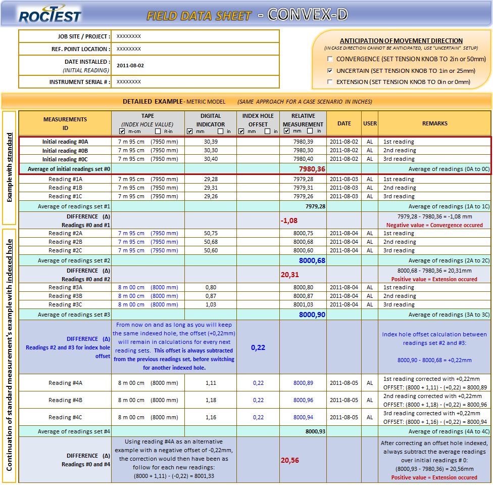
12 Page 10
13 3.3 TEMPERATURE CORRECTIONS -The coefficient of thermal expansion for the steel tape. K tape = 11.6 x 10⁻⁶ meters / meter / ºC -The coefficient of thermal expansion for the the aluminium body of the Instrument. K body = 23 x 10-6 meters / meter / ºC The step below will show you how to make the temperature correction for the steel tape. If required a temperature correction can be done for the aluminium body of the instrument using the same method. Extensometer aluminium body length is approximately 445 mm. How to calculate the change in length of the steel tape: Length is the change in length of the tape due to temperature Tape Length is the summed of the readings on the instrument K tape is the coefficient of thermal expansion of the steel tape Temperature is the change in temperature T current - T initial Length = Tape Length x K tape x Temperature Corrected tape length = Tape Length + Length Exemple: Tape Length is 12.3 meters Temperature is 12 ºC K tape is 11.6 x 10⁻⁶ Length = 12.3 x (11.6 x 10-6 ) x 12 =0.0017m Corrected tape length = 12.3m = m Page 11
14 4 MAINTENANCE 4.1 CLEANING AND LUBRICATION Care should be taken to keep the instrument clean by wiping it with a cloth. Only the tape should be lightly oiled and wiped clean. Any other parts of the instrument (except the tape itself) must not be lubricated. A high quality lubricant has been applied at the factory prior delivery of the instrument on the adjustment knob mechanism and each sliding parts. 4.2 VERIFICATION FRAME An optional verification frame can be supplied. The frame is used to make sure the specified resolution and repeatability of the instrument remain unaffected by shocks, damage or wear. To take a reading on the verification frame, proceed as follows: 1. Attach the hooks on both the tape end and the extensometer head, to the two steel eyes of the verification frame. 2. Tension the tape using the adjustment knob so that the alignment marks are aligned. 3. Using the same field data sheet, note the readings from the digital indicator. 4. Repeat the previous steps (steps 2 and 3) three times and take an average of the readings. 4.3 BATTERY REPLACEMENT To remove the battery, hold the instrument with the digital indicator facing towards the floor. Then, remove the cover and battery using the gravity as help for manipulation. Use the same approach to put a new battery back in place (with the digital indicator facing towards the floor). Battery type: (SR V Silver Oxide Button Battery) Page 12
15 5 MISCELLANEOUS 5.1 CONVERSION FACTORS TYPE TO CONVERT FROM TO MULTIPLY BY LENGTH AREA VOLUME MASS FORCE PRESSURE & STRESS TEMPERATURE at 4 C Microns Millimiters Meters Square millimiters Square meters Cubic centimeters Cubic meters Liters Liters Kilograms Kilograms Kilograms Newtons Newtons Newtons Kilopascals Bars Inches head of water Inches head of Hg Pascal Kilopascals Kilopascals Kilopascals Inches Inches Feet Square inches Square feet Cubic inches Cubic feet U.S. gallon Can Br gallon Pounds Short tons Long tons Pounds-force Kilograms-force Kips Psi Psi Psi PsI Newton / square meter Atmospheres Bars Meters head of water Temp. in F = (1.8 x Temp. in C) + 32 Temp. in C = (Temp. in F 32) / E E6TabConv Page 13

16 5.2 TEMPLATE FOR FIELD DATA SHEET Page 14
VIBRATING WIRE SURFACE STRAIN GAUGE. Model SM-5B. Roctest Limited, All rights reserved.
 INSTRUCTION MANUAL VIBRATING WIRE SURFACE STRAIN GAUGE Model Roctest Limited, 2012. All rights reserved. This product should be installed and operated only by qualified personnel. Its misuse is potentially
WATER LEVEL INDICATOR. Model CPR. Roctest Limited, All rights reserved.
 INSTRUCTION MANUAL WATER LEVEL INDICATOR Model Roctest Limited, 2006. All rights reserved. This product should be installed and operated only by qualified personnel. Its misuse is potentially dangerous.
INSTRUCTION MANUAL ANCHOR LOAD CELL. Model ANCLO
 INSTRUCTION MANUAL ANCHOR LOAD CELL Model ANCLO Roctest Limited 2009. All rights reserved This product should be installed and operated only by qualified personnel. Its misuse is potentially dangerous.
POINT LOAD TESTER. Model PIL-7. Roctest Limited, All rights reserved.
 INSTRUCTION MANUAL POINT LOAD TESTER Model Roctest Limited, 2011. All rights reserved. This product should be installed and operated only by qualified personnel. Its misuse is potentially dangerous. The
VIBRATING WIRE DISPLACEMENT TRANSDUCERS. JM Series. Roctest Limited, All rights reserved.
 INSTRUCTION MANUAL VIBRATING WIRE DISPLACEMENT TRANSDUCERS Series Roctest Limited, 2014. All rights reserved. This product should be installed and operated only by qualified personnel. Its misuse is potentially
Instruction Manual Model 1610
 Instruction Manual Model 1610 Geokon/Ealey Tape Extensometer Office: Jl. Radin Inten II No. 62 Duren Sawit, Jakarta 13440 - Indonesia Workshop: Jl. Pahlawan Revolusi No. 22B, Jakarta 13430 - Indonesia
SENSOPTIC FIBER-OPTIC DISPLACEMENT TRANSDUCER. Model FOD. Roctest Limited, All rights reserved.
 INSTRUCTION MANUAL SENSOPTIC FIBER-OPTIC DISPLACEMENT TRANSDUCER Model FOD Roctest Limited, 2000. All rights reserved. This equipment should be installed and operated only by qualified personnel. Its misuse
Instruction Manual Model 1610
 Instruction Manual Model 1610 Geokon/Ealey Tape Extensometer No part of this instruction manual may be reproduced, by any means, without the written consent of Geokon, Inc. The information contained herein
RETRIEVABLE BOREHOLE EXTENSOMETER. Model BOF-EX. Roctest Limited, All rights reserved.
 INSTRUCTION MANUAL RETRIEVABLE BOREHOLE EXTENSOMETER Model Roctest Limited, 2004. All rights reserved. This product should be installed and operated only by qualified personnel. Its misuse is potentially
VIBRATING WIRE FILL EXTENSOMETER. Model ERI. Roctest Limited, All rights reserved.
 INSTRUCTION MANUAL VIBRATING WIRE FILL EXTENSOMETER Model Roctest Limited, 2009. All rights reserved. This product should be installed and operated only by qualified personnel. Its misuse is potentially
TABLES & CONVERSIONS. Linear Conversions. Mass Conversions. Area Conversions. Mass per Area Conversions. Area per Volume Conversions
 TABLES & CONVERSIONS Linear Conversions inches 25.4 millimeters millimeters 0.039 inches feet 0.3 meters meters 3.28 feet yards 0.91 meters meters 1.09 yards miles 1.61 kilometers kilometers 0.62 miles
Installation Instructions Model Geobeam
 Installation Instructions Model 6700 Geobeam No part of this instruction manual may be reproduced, by any means, without the written consent of Geokon, Inc. The information contained herein is believed
Shearing, bending, and rolling capabilities are available along with fabricating from hand drawn sketches to engineered drawings.
 Tazgo Machine Inc. is a full service stocking warehouse. Items we stock include carbon, aluminum & stainless steel shapes, angles, beams, flats, hex bar, bar grating, squares, CR rounds in 1018,1045 &
VW Surface-Mount Strain Gauge
 VW Surface-Mount Strain Gauge 52650399 Copyright 2003 Slope Indicator Company. All Rights Reserved. This equipment should be installed, maintained, and operated by technically qualified personnel. Any
Instructions for Fitting, Operating and Maintenance
 EN Instructions for Fitting, Operating and Maintenance Retractable Door 1 818 024 RE / 10.2011 ENGLISH Contents 1 Safety Instructions... 3 1.1 Qualified persons... 3 1.2 Symbols and signal words used...
EL Beam Sensors Standard & SC Versions
 EL Beam Sensors Standard & SC Versions 56801399 Copyright 2008 Slope Indicator Company. All Rights Reserved. This equipment should be installed, maintained, and operated by technically qualified personnel.
MSI SINGLE IDLER BELT SCALE
 MSI SINGLE IDLER BELT SCALE Instruction Manual PL-319 January 2001 33453190 Rev. 1.2 Safety Guidelines Warning notices must be observed to ensure personal safety as well as that of others, and to protect
SHAFT ALIGNMENT FORWARD
 Service Application Manual SAM Chapter 630-76 Section 24 SHAFT ALIGNMENT FORWARD One of the basic problems of any installation is aligning couplings or shafts. Therefore, this section will endeavor to
Riverhawk Company 215 Clinton Road New Hartford NY (315) Free-Flex Flexural Pivot Engineering Data
 Free-Flex Flexural Pivot Engineering Data") Riverhawk Company 215 Clinton Road New Hartford NY (315)768-4937 Free-Flex Flexural Pivot Engineering Data PREFACE Patented Flexural Pivot A unique bearing concept for applications with limited angular
Riverhawk Company 215 Clinton Road New Hartford NY (315)768-4937 Free-Flex Flexural Pivot Engineering Data PREFACE Patented Flexural Pivot A unique bearing concept for applications with limited angular
Instructions for Fitting, Operating and Maintenance Canopy Door RE / (St.: )
") EN Instructions for Fitting, Operating and Maintenance Canopy Door 1 818 012 RE / (St.: 12.2010) 12.2010 ENGLISH Contents 1 Safety Instructions... 3 1.1 Qualified persons... 3 1.2 Symbols and signal words
EN Instructions for Fitting, Operating and Maintenance Canopy Door 1 818 012 RE / (St.: 12.2010) 12.2010 ENGLISH Contents 1 Safety Instructions... 3 1.1 Qualified persons... 3 1.2 Symbols and signal words
VW Embedment Jointmeter
 VW Embedment Jointmeter 52632244 Copyright 2003 Slope Indicator Company. All Rights Reserved. This equipment should be installed, maintained, and operated by technically qualified personnel. Any errors
RST INSTRUMENTS LTD.
 RST INSTRUMENTS LTD. Vibrating Wire Crackmeter VWCM Instruction Manual Copyright 2017 Ltd. All Rights Reserved. Ltd. 11545 Kingston St., Maple Ridge, B.C. Canada V2X 0Z5 Tel: (604) 540-1100 Fax: (604)
Instruction Manual August milltronics MMI BELT SCALE
 Instruction Manual August 2003 milltronics MMI BELT SCALE Safety Guidelines Warning notices must be observed to ensure personal safety as well as that of others, and to protect the product and the connected
VW Arc-Weldable Strain Gauge
 VW Arc-Weldable Strain Gauge 52640399 Copyright 2002 Slope Indicator Company. All Rights Reserved. This equipment should be installed, maintained, and operated by technically qualified personnel. Any errors
Appendix. Conversion Factors LENGTH
 Appendix Conversion Factors * LENGTH Inches feet 0.083333 angstrom units 2.54 x 10 8 micros 25400 millis 25.4 centis 2.54 s 0.0254 Feet inches 12.0 angstrom units 3.048 x 10 9 micros 304800 millis 304.80
Instruction Manual August milltronics MSI BELT SCALE
 Instruction Manual August 2003 milltronics MSI BELT SCALE Safety Guidelines Warning notices must be observed to ensure personal safety as well as that of others, and to protect the product and the connected
Albany RR1000. Mechanical Installation Manual. PN: 6410T0029 Version - Rev: 04/23/2014. ASSA ABLOY Entrance Systems
 PN: 6410T0029 Version - Rev: 04/23/2014 Mechanical Installation Manual Albany RR1000 ASSA ABLOY Entrance Systems High Performance Door Solutions Tel: (770) 338-5000 975A Old Norcross Road Fax: (770) 388-5024
Flowserve Spring Diaphragm Rotary Actuators
 Flow Control Division Installation, Operation, Maintenance Instructions Flowserve Spring Diaphragm Rotary Actuators TERMS CONCERNING SAFETY The safety terms DANGER, WARNING, CAUTION and NOTE are used in
Signet 2517 Brass Paddlewheel Flow Sensor * *
 Signet 2517 Brass Paddlewheel Flow Sensor -250.090 English -2517.090 Rev. F 11/06 English SAFETY INSTRUCTIONS 1. Do not remove from pressurized lines. 2. Do not exceed maximum temperature/pressure specifi
Pipe fi ttings MUST be installed by a certifi ed welder only. Signet will not assume liability of any kind for improper fi tting installations.
 Signet 50 High Performance Flow Sensor English *3-50.090* 3-50.090 C 05/06 English SAFETY INSTRUCTIONS 1. Do not remove from pressurized lines.. Do not exceed maximum temperature/pressure specifi cations.
AUTO REWIND AIR HOSE REEL
 Model #s 46845, 46848 AUTO REWIND AIR HOSE REEL OPERATOR S MANUAL STORE THIS MANUAL IN A SAFE PLACE FOR FUTURE REFERENCE!? NEED HELP? Save time, contact us first. 888-648-8665 support@tekton.com WARNING:
TL4076 Top 5 Tips Get to know your TL4076
 TL4076 Top 5 Tips Get to know your TL4076 Thermal Break with Teflon liner (behind fan) Hot End Assembly Fan Heat Block Extruder with toothed gear(brass) and idler (steel) Filament Guide Tube Nozzle Cable
MF205, MF205-4, MF210, MF210-4, MF220 & MF220-4 Compact
 Massey Harris Massey Ferguson Service Manual MF205, MF205-4, MF210, MF210-4, MF220 & MF220-4 Compact Service Manual THIS IS A MANUAL PRODUCED BY JENSALES INC. WITHOUT THE AUTHORIZATION OF MASSEY HARRIS
RB12 AERO - DUAL INSTALLATION MANUAL. February 2017
 RB12 AERO - DUAL INSTALLATION MANUAL February 2017 CONTENTS February 2016 This manual is to be read in conjunction with the Product Specifications & Assembly manual SECTION NO. DESCRIPTION PAGE NO. SECTION
Instruction Manual. Model (Model A9) Retrievable Extensometer
 Retrievable Extensometer") Instruction Manual Model 1300 (Model A9) Retrievable Extensometer No part of this instruction manual may be reproduced, by any means, without the written consent of Geokon, Inc. The information contained
Instruction Manual Model 1300 (Model A9) Retrievable Extensometer No part of this instruction manual may be reproduced, by any means, without the written consent of Geokon, Inc. The information contained
RST INSTRUMENTS LTD.
 RST INSTRUMENTS LTD. MEMS Portable Tiltmeter System (Biaxial) Instruction Manual Model ICTS0004, IC6800S Readout Copyright 2012 Ltd. All Rights Reserved. Ltd. 11545 Kingston St., Maple Ridge, B.C. Canada
MECHANICAL ENGINEERING FORMULAE
 MECHANICAL ENGINEERING FORMULAE Power & Torque Imperial Standards Horsepower (HP) Common unit of mechanical power, one HP is the rate of work required to raise 33,000 pounds one foot in one minute. Metric
Pipe fittings MUST be installed by a certified welder only. +GF+ SIGNET will not assume liability of any kind for improper fitting installations.
 +GF+ SIGNET 0 High Performance Flow Sensor (English) -0.090- F-/99 English SAFETY INSTRUCTIONS. Do not remove from pressurized lines.. Do not exceed maximum temperature/pressure specifications.. Do not
OPERATOR S MANUAL 2200 SERIES LIFT - LIL HOISTER. July 2017
 July 2017 OPERATOR S MANUAL 2200 SERIES LIFT - LIL HOISTER! Before operating this lift, read and understand this Operator s Manual. Become familiar with the potential hazards of this unit. Call SUMNER
VW Embedment Strain Gauge
 VW Embedment Strain Gauge 52650199 Copyright 2003 Slope Indicator Company. All Rights Reserved. This equipment should be installed, maintained, and operated by technically qualified personnel. Any errors
FIBERGLASS RODS BOREHOLE EXTENSOMETER WITH GROUTABLE ANCHORS AND VW SENSORS Model BOREX-E. Roctest Limited, All rights reserved.
 INSTRUCTION MANUAL FIBERGLASS RODS BOREHOLE EXTENSOMETER WITH GROUTABLE ANCHORS AND VW SENSORS Model BOREX-E Roctest Limited, 2015. All rights reserved. This product should be installed and operated only
Larson Systems Inc. V200, V750 and V1500 Digital Valve Spring Tester User Manual. Current for Software Version 6.9
 Larson Systems Inc. V200, V750 and V1500 Digital Valve Spring Tester User Manual Current for Software Version 6.9 About This Manual This manual could contain technical inaccuracies or typographical errors.
HANDY GATE ASSEMBLY, INSTALLATION AND OPERATING INSTRUCTIONS
 ASSEMBLY, INSTALLATION AND OPERATING INSTRUCTIONS BEFORE INSTALLING OR USING THE, REVIEW THE VEHICLE LOADING LIMITATIONS OUTLINED IN THE VEHICLE OWNER S MANUAL AND THE SAFETY COMPLIANCE CERTIFICATION LABEL
Wood Chipper Model C550M Operator's Manual
 Wood Chipper Model C550M Operator's Manual THIS MANUAL MUST BE READ AND UNDERSTOOD BEFORE ANYONE OPERATES THIS MACHINE! Manual# 990023 Revised 01/2010 YOU MUST FILL OUT YOUR WARRANTY REGISTRATION TO ACTIVATE
Series Low Pressure Steam Heating Boiler Safety Valves
 12-200 Series Low Pressure Steam Heating Boiler Safety Valves Section IV Heating Boilers Medium capacity safety valves protect ASME Section IV low pressure steam heating boilers. Cast bronze, full nozzle
Config file is loaded in controller; parameters are shown in tuning tab of SMAC control center
 Measuring Forces Force and Current limits on LCC The configuration file contains settings that limit the current and determine how the current values are represented. The most important setting (which
Predelivery Instructions
 PINK Predelivery Instructions SR5030 Split-Row Planter Manufacturing, Inc. P.O. Box 5060 Salina, Kansas 67402-5060! Read this manual entirely. When you see this symbol, the subsequent instructions and
Objectives: I can convert units using conversion factors in the same system. I can convert units using conversion factors between systems.
 Unit 1: Relationships between Quantities and Reasoning with Equations Lesson 1- Converting Units Objectives: I can convert units using conversion factors in the same system. I can convert units using conversion
POCKET GUIDE for TROUBLESHOOTING Gas Products To be used by F.P.I. trained service technicians only.
 POCKET GUIDE for TROUBLESHOOTING Gas Products To be used by F.P.I. trained service technicians only. 908-489 02/26/99 Table of Contents Tools and Instruments...3 Problem A Pilot not igniting after repeated
Heavy Duty Miniature Quick-Change Applicator (Side-Feed Type) with Mechanical or Air Feed Systems
 with Mechanical or Air Feed Systems") Heavy Duty Miniature Quick-Change Applicator (Side-Feed Type) with Mechanical or Air Feed Systems Instruction Sheet 408-8040 30 NOV 17 Rev H Ram Assembly Ram Post Locking Screw Stock Drag Drag Release
Heavy Duty Miniature Quick-Change Applicator (Side-Feed Type) with Mechanical or Air Feed Systems Instruction Sheet 408-8040 30 NOV 17 Rev H Ram Assembly Ram Post Locking Screw Stock Drag Drag Release
Reference Booklet. Frequently Used Conversion and Calculation Charts.
 PM-GFRB-1 $4.00 Reference Booklet Frequently Used Conversion and Calculation Charts. A Canadian Company Propane & Natural Gas Barbecue Outlets Vancouver Calgary Edmonton Saskatoon Winnipeg Toronto Montreal
RST INSTRUMENTS LTD.
 RST INSTRUMENTS LTD. MEMS In-Place Inclinometer System Instruction Manual Copyright 2018 Ltd. All Rights Reserved. Ltd. 11545 Kingston St., Maple Ridge, B.C. Canada V2X 0Z5 Tel: (604) 540-1100 Fax: (604)
Series Low Pressure Steam Boiler Safety Valves
 14-200 Series Low Pressure Steam Boiler Safety Valves ASME Section IV Set pressures from 5 to 15. Sizes 2", 2-1/2" and 3". Section IV Heating Boilers Applications: The 14 Series is an ASME Section IV high
USER INSTRUCTIONS. Spring Diaphragm Rotary Actuators. Installation Operation Maintenance. Experience In Motion FCD VLAIM /12
 USER INSTRUCTIONS Spring Diaphragm Rotary Actuators FCD VLAIM050-01 05/12 Installation Operation Maintenance Experience In Motion Contents General Information 3 Unpacking 4 Installation 4 Changing Air
Stainless Steel Gas Springs Page 6-0-1
 316 QUALITY STAINLESS STEEL GAS SPRINGS PROGRAM Stainless Steel Gas Springs Page 6-0-1 ALL OUR GASSPRINGS ARE EXECUTED WITH VALVE AND NITRITE SEAL AND ARE PRODUCED UNDER LLOYDS CONTROLLED AND CERTIFIED
KEYSTONE F89 PNEUMATIC QUARTER-TURN ACTUATOR GENERAL PURPOSE / HAZARDOUS AREA
 FEATURES Direct mounting to all Keystone butterfly valves and ball valves. Valve connection compatible with Keystone (imperial and metric) and ISO 5211. Double Rack and Pinion design nullifies side loads
PUSH BUTTON KEY CABINET
 PUSH BUTTON KEY CABINET Model 95689 INSTALLATION And Operation Instructions Due to continuing improvements, actual product may differ slightly from the product described herein. 3491 Mission Oaks Blvd.,
VW Embedment Strain Gauge
 VW Embedment Strain Gauge 52640199 Copyright 2004 Slope Indicator Company. All Rights Reserved. This equipment should be installed, maintained, and operated by technically qualified personnel. Any errors
Operating & Maintenance Instructions Thermobend Elite Range
 Operating & Maintenance Instructions Thermobend Elite Range Table of Contents 1. Setting Up... 2 1.1 Introduction... 2 1.2 Location & Assembly... 4 1.3 Electrical Supply & Connection... 5 1.4 Pneumatic
Pipe fi ttings MUST be installed by a certifi ed welder only. Signet will not assume liability of any kind for improper fi tting installations.
 Signet 50 High Performance Flow Sensor English *3-50.090* 3-50.090 Rev. F 11/1 English For the most up-to-date information, please refer to our website at www.gfsignet.com SAFETY INSTRUCTIONS 1. Do not
BOSS STEEL Metal Reference Book Version 9
 Intro BOSS STEEL Metal Reference Book Version 9 This ninth edition of the Boss Steel Metal Reference Book has been designed to inform and assist you in making the right decision when it comes to acquiring
FBD-NT Press Brake Installation Guide
 FBD-NT Press Brake Installation Guide Summary...2 Environmental conditions...2 Power supply...2 Machine installation...3 Location...4 Carrying...5 Using a crane...5 Using rollers...6 Foundation...7 Cleaning...7
PRODUCT CATALOGUE LOUCON METAL LTD. 37 and 39 Grenfell Crescent, Nepean, ON K2G 0G3. Hours of Operation: Monday-Friday 8:00 AM 5:00 PM
 PRODUCT CATALOGUE 37 and 39 Grenfell Crescent, Nepean, ON K2G 0G3 Hours of Operation: Monday-Friday 8:00 AM 5:00 PM Phone: (613) 226-1102 Fax: (613) 226-6097 e-mail: info@louconmetal.com web: www.louconmetal.com
Config file is loaded in controller; parameters are shown in tuning tab of SMAC control center
 Forces using LCC Force and Current limits on LCC The configuration file contains settings that limit the current and determine how the current values are represented. The most important setting (which
PLUMBING MATHEMATICS
 PLUMBING MATHEMATICS A review of basic fundamentals of mathematics is essential to successful applications of plumbing principals. An acceptable reference that may be used during your examination is Mathematics
Keystone F89 pneumatic quarter-turn actuator General purpose / hazardous area
 Compact, reliable and low operation costs for all types of quarter-turn valves are the keywords of the Keystone F89 range of pneumatic actuators Features Direct mounting to all Keystone butterfly valves
KEYSTONE F89 pneumatic quarter-turn actuator GENERAL PURPOSE / HAZARDOUS AREA
 compact, reliable and low operation costs for all types of quarter-turn valves are the keywords of the Keystone F89 range of pneumatic actuators FEATURES Direct mounting to all Keystone butterfly valves
6.0 SPECIFICATIONS CONTENTS. Calibration. According to factory procedureeeeeeeeeeeeeee Accuracy*
 6.0 SPECIFICATIONS Calibration According to factory procedureeeeeeeeeeeeeee Accuracy* ± 1% full scale (FS) or ± 1 graduation on scale Scale diameter 41 mm Temperature range 45 to 115 F (10-45 C) Air humidity
Installation Instructions X-Force UTV Lift (000 Series) Capacity 2,275 lbs (1,035 kg)
 Capacity 2,275 lbs (1,035 kg)") Installation Instructions X-Force UTV Lift (000 Series) Capacity 2,275 lbs (1,035 kg) Read entire manual before assembling, installing, operating, or servicing this equipment. LP20640 IN20793 September
Installation Instructions X-Force UTV Lift (000 Series) Capacity 2,275 lbs (1,035 kg) Read entire manual before assembling, installing, operating, or servicing this equipment. LP20640 IN20793 September
Vibrating Wire Soil Extensometer Manual
 Vibrating Wire Soil Extensometer Manual All efforts have been made to ensure the accuracy and completeness of the information contained in this document. RST Instruments Ltd reserves the right to change
OPERATOR'S MANUAL AND MAINTENANCE INFORMATION MODEL T-2000 TEXTURE TEST SYSTEM
 OPERATOR'S MANUAL AND MAINTENANCE INFORMATION MODEL T-2000 TEXTURE TEST SYSTEM This Publication contains information proprietary To Food Technology Corporation The contents of this publication may not
B4A Instruction Manual
 Page 1 TABLE OF CONTENTS Vehicle Preparation 2 Floor Slope Calibration 2 Headlamp Aiming 4 Assembly Instructions / Large and Small Universal Adaptors 6 Aiming Instructions 8 Quick Headlamp Aim Check 15
RST INSTRUMENTS LTD.
 RST INSTRUMENTS LTD. Tunnel Convergence Meter Instruction Manual Copyright 2012 Ltd. All Rights Reserved. Ltd. 11545 Kingston St., Maple Ridge, B.C. Canada V2X 0Z5 Tel: (604) 540-1100 Fax: (604) 540-1005
Application Tooling Specification Sheet
 Tool Kit Order No. 63825-6270 FEATURES Application Tooling Specification Sheet TYPE 4C Hand Crimp Tool Order No. 63825-6200 % A full cycle ratcheting hand tool ensures complete crimps % Ergonomically designed
MSI SINGLE IDLER BELT SCALE
 MSI SINGLE IDLER BELT SCALE Instruction Manual PL-319 February 1992 33453190 PRR 1.1 Siemens Controls Thank you for purchasing Milltronics products. We endeavour to design equipment that is simple to use
BX7460P Allure Tow Bar Operator Manual & Installation Instructions. ALLURE Tow Bar (10,000 lb) Pintle Coupler
 Pintle Coupler") Operator Manual & Installation Instructions ALLURE Tow Bar (10,000 lb) Pintle Coupler Hooking Up to Towed Vehicle 1. Position the towing vehicle on a level surface with a straight driveway ahead and engage
Operator Manual & Installation Instructions ALLURE Tow Bar (10,000 lb) Pintle Coupler Hooking Up to Towed Vehicle 1. Position the towing vehicle on a level surface with a straight driveway ahead and engage
MILLTRONICS UNIVERSAL SCALE NIVERSAL SCALE Rev. 1.2
 MILLTRONICS UNIVERSAL SCALE NIVERSAL SCALE 33455530 Rev. 1.2 Safety Guidelines Warning notices must be observed to ensure personal safety as well as that of others, and to protect the product and the connected
Installation Manual TWM Performance Short Shifter Cobalt SS/SC, SS/TC, HHR SS, Ion Redline and Saab 9-3
 Page 1 Installation Manual TWM Performance Short Shifter Cobalt SS/SC, SS/TC, HHR SS, Ion Redline and Saab 9-3 Please Note: It is preferable to park on a flat surface, as you will have to engage and disengage
WARNING this attachments capacity changes depending on the Skid Steer Loader it is hooked up to. CAPACITY AT 24 LOAD CENTER
 SKID STEER FORKLIFT ATTACHMENT Any piece of equipment can be dangerous if not operated properly. YOU are responsible for the safe operation of this equipment. The operator must carefully read and follow
Application Tooling Specification Sheet
 Tool Kit Order No. 63811-7570 FEATURES Application Tooling Specification Sheet TYPE 2C Hand Crimp Tool Order No. 63811-7500 % A full cycle ratcheting hand tool ensures complete crimps % Ergonomically designed
Installation & Calibration
 Installation & Calibration ED2-AT Series SkidWeigh System Lift Truck On-board Check Weighing With Accumulative Load Weight Total ED2-AT Series SkidWeigh V.1.1 General Installation Guide This ED2-AT Series
SETTING ZERO S cont. IF THE ZERO REPEATS WITHIN +/- 1.0 LB THEN YOU ARE READY TO CHECK SPRINGS. PAGE 4 OF 9
 SETUP REMOVE THE NUTS AND WASHERS FROM THE BOTTOM OF THE CRATE. REMOVE THE SCREWS THAT SECURE THE HANDLE IN THE CRATE. NOW CAREFULLY LIFT THE UNIT AND THE HANDLE OUT AND PLACE ON TABLE RESTING ON THE THREADED
Siderolling Tarp Systems Under 9 6 Wide
 Load Loc Select Maximizer Grain Carts Grain Bagger Siderolling Tarp Systems Under 9 6 Wide CRANK STYLE INSTALLATION INSTRUCTIONS MICHEL S INDUSTRIES, LTD. P.O. BOX 119 ST. GREGOR, SK. S0K 3X0 PH:306.366.2184
Installation Instructions
 86-89 Suzuki Samurai Pedal Rebuild Kit SKU# SIB-PRB! Instructions also includes clutch adjustment procedures. Installation Instructions W e a l s o s u p p l y replacement peddle pads. Click HERE for more
Thank you for purchasing a Nelson RainTrain2.
 Thank you for purchasing a Nelson RainTrain2. Read this manual carefully to learn how to operate and service your machine properly. Failure to do so can result in personal injury and/or property damage.
Lockpicking Tools: User Guide
 Lockpicking Tools: User Guide Tips & Tricks for using Lockpicking Tools Contents Introduction..3 Padlock Shims..5 Comb Picks....7 Jiggler Keys...9 The Lock Gun..11 Bypass Sheets....13 Bump Keys...14 Other
Assembly & Operator s Manual
 Assembly & Operator s Manual LiftGator XTR 1200lbs Removable Liftgate TM Visit our website at: www.liftgator.com WARNING: Read the entirety of this manual before using the LiftGator. Failure to do so can
truck crane 140 tons link-belt htc-3140lb BOOM LENGTHS: 42 to 195 ft JIB LENGTHS: 38 to 109 ft JIB OFFSETS:
 truck crane 140 tons link-belt htc-3140lb BOOM LENGTHS: 42 to 195 ft JIB LENGTHS: 38 to 109 ft JIB OFFSETS: 2-15 - 30-45 NOTES: Technical Data Specifications & Capacities Telescopic Boom Truck Crane 140
Personal Protection Equipment (PPE) Safety Glasses Protect eyes Welding Mask Protect eyes and face
 Safety Glasses Protect eyes Welding Mask Protect eyes and face") Table of Contents: Title Page... 1 Introduction... 3 Before Construction... 3 Equipment Needed... 3 Drawings... 4 Construction... 5 1. Cut Sheet Drawings... 5 2. Base... 5 3. Combustion Chamber... 12 4.
Table of Contents: Title Page... 1 Introduction... 3 Before Construction... 3 Equipment Needed... 3 Drawings... 4 Construction... 5 1. Cut Sheet Drawings... 5 2. Base... 5 3. Combustion Chamber... 12 4.
FLUID POWER FLUID POWER EQUIPMENT TUTORIAL PIPE WORK. This work covers part of outcome 2 of the Edexcel standard module:
 FLUID POWER FLUID POWER EQUIPMENT TUTORIAL PIPE WORK This work covers part of outcome 2 of the Edexcel standard module: UNIT 21746P APPLIED PNEUMATICS AND HYDRAULICS The material needed for outcome 2 is
VARIABLE VOLUME RESERVOIR (VVR) FOR INDUSTRIAL AND MOBILE APPLICATIONS
 FOR INDUSTRIAL AND MOBILE APPLICATIONS") SOBACOR inc. 812 boul. Industriel Bois-des-Filion, Québec Canada J6Z 0A3 450-965-9669 450-965-9690 sobacor@sympatico.ca www.sobacor.com VARIABLE VOLUME RESERVOIR (VVR) FOR INDUSTRIAL AND MOBILE APPLICATIONS
SOBACOR inc. 812 boul. Industriel Bois-des-Filion, Québec Canada J6Z 0A3 450-965-9669 450-965-9690 sobacor@sympatico.ca www.sobacor.com VARIABLE VOLUME RESERVOIR (VVR) FOR INDUSTRIAL AND MOBILE APPLICATIONS
Standard Specification for ASTM Hydrometers 1
 Designation: E 100 03 Standard Specification for ASTM s 1 This standard is issued under the fixed designation E 100; the number immediately following the designation indicates the year of original adoption
CRANE RATING MANUAL HTC
 SERIAL NUMBER: XXXX- XXXX CRANE RATING MANUAL HTC- 8611 TELESCOPIC BOOM TRUCK CRANE - 164.1 SIX SECTION LATCHING BOOM For Replacement, Order Part Number: T2P38 (116) R Link-Belt is a registered trademark.
Table of Contents Next FLO-SAFE Manifold System Pre-Installation Kit Matrx Toll-Free: Technical Support: Fax: Rev.
 FLO-SAFE Manifold System Pre-Installation Kit Instruction Manual Matrx 145 Mid County Drive Orchard Park, New York 14127 716-662-6650 Toll-Free: 800-847-1000 Technical Support: 888-279-1260 Fax: 716-662-8440
IC80 Series INTRODUCTION
 SN-PL/2011/002 IC80 Series INTRODUCTION Sankyo America, Inc. is proud to offer the IC80 inline chassis precision link conveyor to manufacturers around the world. This innovative design features zero-backlash
500R MIXER SYPHON TYPE WATER TANK WORKSHOP MANUAL
 500R MIXER SYPHON TYPE WATER TANK WORKSHOP MANUAL WINGET LIMITED PO BOX 4 EDGEFOLD INDUSTRIAL ESTATE PLODDER LANE BOLTON LANCS BL4 OLS TEL: ++ 44 (0) 04 854650 FAX: ++ 44 (0) 04 854663 service@winget.co.uk
Keystone F89C Pneumatic Quarter-Turn Actuator Chemical Industry / Hazardous area
 The F89C addresses the specific requirements for automated quarter-turn valves in the chemical industry on top of the reliability and low maintenance cost offered Features Valve connection compatible with
Instruction Manual MODEL: AC TRACKTECH T Rev. C. World s First Portable, Remote-Control Aircraft Tugs
 Instruction Manual MODEL: AC TRACKTECH T1.5 95328 Rev. C World s First Portable, Remote-Control Aircraft Tugs Contents 1. Components 1-1. Components in the Box 1-2. Tug Components 1-3. Radio Components
Tooling Assistance Center
 Safeguards are designed into this application equipment to protect operators and maintenance personnel from most hazards during equipment operation. However, certain safety precautions must be taken by
HD 7700 Setup & Operator Manual
 HD 7700 Setup & Operator Manual Issue 1 December, 01 Performance Design Inc. The Heavy Duty Ultima (HD 7700) electric punch has been designed to punch most any job that may pass through your bindery or