CONDUCTIX Insul-8 Conductor Bar
|
|
|
- Damian Moody
- 6 years ago
- Views:
Transcription

1


2 CONDUCTIX Insul-8 Conductor Bar CONDUCTIX has designed and built state-of-the-art conductor bar systems for over 60 years. The US branch of Conductix was founded in 1944 as Insul-8 Corporation. Insul-8 developed the first figure 8 conductor bar system, which became the standard method of electrifying overhead cranes. In 1975, Insul-8 became part of the worldwide Delachaux Group. In 1991 the company moved its manufacturing facility to the current location in Harlan, Iowa. Now under the name CONDUCTIX, the company continues as a world leader in the design and manufacture of highperformance conductor bar systems for industrial applications. Recent innovations include the new finger-safe SAFELEC 2 V-contact bar and the Hevi-Bar II conductor system. CONDUCTIX bar is manufactured in the USA to provide quick delivery, many configurations and options, and competitive prices. Our experienced engineering and sales people are recognized experts in the application of conductor bar systems to solve industrial problems. We offer a complete complement of mobile electrification products including Cable Festoon Systems, Cable Chain, Cable Reels, Push-Button Pendants, Radio Remote Controls, and Crane Bumpers. All CONDUCTIX manufacturing facilities are ISO 9001:2000 certified. Our stringent quality systems assure that you will get the right product every time. Omaha, NE Plant Harlan, IA Plant SAFELEC 2 The new industry standard for crane, monorail, and material handling electrification. Easy to install and maintain. Collector shoes track accurately on V-contact bar. Requires fewer joints and expansion sections than other systems. Finger-safe (IP2 rated). Can be mounted for bottom or lateral entry. Heater wire system available for cold climates; black UV resistant cover for outdoor applications. UL Listed Hevi-Bar II The ideal conductor bar system for large process cranes and material handling equipment used in mills and other heavy industrial applications. Aluminum body efficiently dissipates heat; stainless steel V contact surface for accurate shoe tracking and long wear. Can be mounted for bottom or lateral entry. Heater wire system available for cold climates; black UV resistant cover for outdoor applications. UL / CSA Listed


3 CONDUCTIX Insul-8 Conductor Bar Originally developed by Insul-8 over 60 years ago, was the first insulated conductor system for crane/monorail electrification. If you need 8-bar, insist on the original! has many special options and components developed over 60 years of applications. The basic system is designed for bottom entry. A unique Side Contact system is available for lateral mounting. Able to accommodate small bend radii for curved systems and slip rings. UL / CSA Listed Side Contact Cluster Bar A compact conductor bar system with 3/4 minimum spacing between bars. For small cranes, material handling applications, and automated storage/retrieval systems. Finger-safe IP2 rating. Able to accommodate small bend radii for curved systems and slip rings. Can be mounted for bottom or lateral entry. CSA Listed Conductor Bar Summary Chart Specification SAFELEC 2 Hevi-Bar II Side Contact Cluster Bar Ampacity 60, 100, 125, 160, 200, 250, 315, , 700, 1000, , 90, 110, 250, 350, , 90, 110, 250, 350 Max. Voltage / , 120 Speed 1200 fpm 2000 fpm 900 fpm 600 fpm 600 fpm Spacing Between Conductors Max Cover Temperature: Low = 160 O F; Med. = 250 O F, High = 400 O F Low, Med Low (all amps), Med. (all amps), High (700 &1000A) Low, Med, High Low, Med Low Environment Indoor or Outdoor Indoor or Outdoor Indoor or Outdoor Indoor Indoor Corrosion Protection Option No Yes 40A only 40A only No Orientation (Collector Entry) Bottom or Side Bottom or Side Bottom or Side Side Bottom or Side Min. Bend Radius, Low Temp 60 Consult Factory 18 (45 the long way ) 9 16 Min. Bend Radius, Med Temp 60 Consult Factory N/A Heater Wire Available Yes 500 & 1500A only No No No Common Applications Small to Medium overhead cranes, moderate curves Medium to large overhead cranes, higher speeds Small to medium overhead cranes, tighter curves Constrained spaces, slip ring applications Monorail hoists, switches, constrained spaces, > 4 conductors If you don t see what you need, give us a call. We offer thousands of special designs and options!
4 Conductor Bar Data Sheet - Quote Request Fax to: or to: info@conductix.us Request Date / / Sales Person Company Company Type Contact Title Tel Fax APPLICATION 1. Application Type: Runway Bridge Monorail Other 2. New Approved Installation? Extended Existing? Replacement? 3. System Length: (feet) 4. Total # of Conductors: ENVIRONMENTAL DATA Will one conduct be designated as a ground? Yes No Describe the environment where the conductor system will be located: 1. Indoors Outdoors Both Indoors and Outdoors Outdoor & Ice 2. Ambient temperature range: Min. Max. Degrees F 3. Will a heater wire need to be included? Yes No (If yes, consult factory) 4. Is there a source of corrosion present? Yes No If yes, describe the corrosive: Refer to Appendix I Pg Other environmental considerations (dust, etc.)? MECHANICAL DATA 1. Vehicle Speed (feet per min.) Duty Cycle: 2. Number of vehicles or trolleys: Crane Class (if applicable) Refer to Appendix I Pg Will CONDUCTIX be supplying mounting brackets? Yes No 4. Does the system include any curves? Yes No (if yes, consult factory) 5. Other mechanical notes: ELECTRICAL SPECIFICATIONS 1. Number of power feeds: 2. Location of power feeds (check all that apply): Center Multiple End Advanced: Distance power feeds will be from end of system: Refer to Appendix I Pg. 98 (or attach diagram) 3. Number of power phases: Operating voltage: (volts) AC DC 4. Total current draw: (sum of all vehicles ) (Amps) Demand factor Q (typically.9) 5. Operating Frequency (Hz - U.S. is 60 Hz)


5 Conductor Bar Data Sheet - Quote Request Q Sizing systems for multiple hoists, motors, and/or multiple cranes For a single crane: Size the conductor bar to handle 100% of the current draw of the largest motor or group of motors, plus 50% of the combined current draw of the other motors on the vehicle. For multiple cranes or vehicles: Determine the current draw for each crane/vehicle, using the method above. Sum all the current draws for each crane/vehicle, then multiply the sum by the appropriate demand factor: # of Cranes/vehicles Demand Factor Conductix Quick Quote Software If you configure or purchase conductor bar systems, festoon systems, push button pendants, radio controls, and cable reels on a regular basis, you need a copy of our innovative Quick Quote software! This advanced program automatically configures complete systems. It generates bills of materials, quotations, and system drawings. You can also load your customers into the program and send quotes automatically. You can turn your quote into an order with a click! Here is just a partial list of Quick Quote s advanced features: Conductor Bar Systems: l Calculates crane amp draw with multiple vehicles l Automatically calculates and graphs voltage drop given single or multiple power feed locations l Handles advanced bar and collector mounting configurations l Provides conductor bar system schematic Festoon Systems: l Handles advanced festoon mounting configurations l Allows set-up cable package arrangements and clamp configurations l Handles festoon pre-wiring and pre-assembly options Pendants & Radios: l Handles custom ratio applications and kits l Handles custom pendant configurations Contact Conductix Sales today at or us at info@conductix.us for more information. Quick Quote is supplied on our CD ROM All Catalogs and Quick Quote, which can be ordered on from the Catalogs section. The program requires an access code which can be obtained from Conductix.
6 Table of Contents Conductix Conductor Bar Products - Overview 2-3 Conductor Bar Summary Chart 3 Quotations Data Sheet 4 Quick Quote Software 5 Table of Contents 6-7 SAFELEC 2 Overview and Design Features 8-9 Typical 4-Bar System 10 Electrical Ratings Specifications 13 System Components Galvanized Steel Bar (60, 100, 125A) 14 Copper Bar (160, 250, 400A) 15 Aluminum/Stainless Steel Bar (200, 315, 400A) 16 Splice Joints and Joint Compound 17 Power Feeds Hanger Clamps Anchor Clamps 19 End Caps 20 Pick Up Guides 20 Power Interrupting Sections 21 Collectors and Shoes 22 Hanger Brackets 23 Collector Brackets 23 Girder Clamps 23 Heater Wire System 24 SAFELEC 2 Dimensions Installed 25 Collectors 26 Components Brackets HEVI-BAR II Overview and Design Features 32 DURA-COAT Corrosion Protection 32 Typical 4-Bar System 33 Specifications 46 Conductor Bar, Expansion Sections, Splices, Power Feeds, Power Interrupting Sections, End Covers 500A A A A Collectors and Shoes 42 Support Brackets 500A A / 1000A / 1500A Hevi-Bar II Dimensions Installed 47 Bar Profiles 48 Expansion Sections 48 Splice Joints 49 Power Feeds 50 Power Interrupting Sections 51 End Covers 52 Collectors INSUL-8 TM 8-BAR Overview, Design Features, and Main Components 55 Typical 4-Bar System 56 Specifications 57 Conductor Bar Stainless Steel Bar (40A) 58 Galvanized Steel Bar (90, 110A) 58 Stainless Clad Copper Bar (250A) 58 Copper Steel Laminate Bar (250A) 59 Rolled Copper Bar (350A) 59 Solid Copper Bar (500A) 59
7 Table of Contents System Components Bar Cover 60 Connector Pins & Joint Covers 60 Copper Connector Clamp 61 Joint Keeper 61 Joint Repair Kit 61 Connector Tool 61 End Cover 62 Power Feed 62 Expansion Sections 63 Isolation Section and s 63 Transfer Caps 64 Pick Up Guides 64 Hanger Clamp 65 Collectors and Shoes Hanger Brackets Curves and Slip Rings Dimensional Pages SIDE CONTACT Overview and Main Components 76 Conductor Bar Stainless Steel Bar (40A) 77 Galvanized Steel Bar (90, 110A) 77 Stainless Clad Copper Bar (250A) 78 Copper Steel Laminate Bar (250A) 78 Rolled Copper Bar (350A) 78 Expansion Sections 78 System Components Connector Pins 79 Bar Cover 79 End Covers 79 Power Feed 80 Pick Up Guide 80 Hanger Clamps and Brackets 81 Collectors Collector Dimensions 84 Slip Rings and Curves 85 CLUSTER BAR Overview Design Features 86 Typical 4-Bar System 87 Specifications 88 System Components Conductor Bar (40, 120A) 89 Expansion Sections 89 Power Feed 89 End Power Feed 90 End Cover and Splice Cover 90 Crimping Tool 90 Splice Joint 91 Transfer Cap 91 Pick Up Guide 91 Isolation Section 91 Isolation Kit 92 Power Interrupting Section 92 Take Up Section 92 Hanger and Anchor Clamps 93 Brackets Collectors and Mounting Staff 95 Slip Rings, Curves and Curving Machine 96 APPENDICES I - Selection of Conductor Bar Systems II - Manual Voltage Drop Calculations 101 III - Electrical Formulas and Conversions 102 IV - Power Interrupting Sections About Conductix 105 Terms and Conditions 106 Conductor Bar in Action 107 Conductix Worldwide Locations 108


. l In stock availability for quick shipment l A large number of special options and adaptations developed over 70 years of usage to handle numerous industrial situations.")

8 Insul-8 TM Overview Conductix Insul-8 TM, designed by Insul-8 Corporation over 50 years ago - the original figure 8 conductor bar system! This innovative system provided the first safe, insulated electrification solution for cranes, monorails, hoists, conveyors, and many other applications. Hundreds of miles of this bar system are in use all around the world. There are many copy cat systems around - don t settle for imitations - get the original system! UL and CSA Listed Insul-8 TM Features: Designed and built in the USA under stringent ISO 9001: 2000 standards Wide current range: 40A, 90A, 110A, 250A, 350A, 600 volts max. Maximum Speed: 900 fpm Many Options: Stainless steel hardware, green bonding (ground) conductor covers, black UV stable outdoor covers, curved systems to 18 minimum radii (the easy way) or 45 the hard way (low heat cover). l In stock availability for quick shipment l A large number of special options and adaptations developed over 70 years of usage to handle numerous industrial situations. l The ability to be curved into a tighter radius than most other systems. l Knurled joins pins for secure joints. Won t pull apart under normal conditions when properly installed. l Backed by the best customer service and engineering services in the industry. installs quickly and easily: l Minimum number of basic parts l Quick pin-style splice joints l Bar snaps into mating hanger End Cover 1 Square Bar Power Feed Collector Hanger Clamp Conductor Power Feed: Conducts the power source to the conductor bar Collector: Collects power from the bar and transfers it to the moving machine. Connects to a 1 mounting staff Hanger Clamp: Supports the conductor bar End Cover: Caps off the end of the conductor bar Bracket: Attaches to crane beam or other structure to support multiple hangers Anchor Clamp: Connects the bar to the structure and directs movement of the conductors during thermal expansion/contraction Automate your work with our advanced Quick Quote software - see Pg
9 Typical 4-Bar System EXAMPLE OF 4 CONDUCTOR RUNWAY 8 BAR (3 PHASE + 1 GROUND) 175' Max Steel 8 Bars 125' Max Copper 8 Bars Unless otherwise specified 300' Max Steel 8 Bars 200' Max Copper 8 Bars For 100 F Temperature Change 175' Max Steel 8 Bars 125' Max Copper 8 Bars Unless otherwise specified 1'-6" Recommended 6" Minimum Anchor Point 6" Minimum to Expansion Section Powerfeed 6" Minimum Powerfeed 2'-6" Max End Cover Hanger Clamp Recommended Hanger Spacing: 5'-0" for Vertical Entry 3'-0" for Curves 3'-4" for Lateral Entry Joint 10'-0" Expansion Section Required In Runs Longer Than: 350' for 40, 90 & 110 Amps 250' for 250, 350 & 500 Amps Use Anchor Clamp at Center 2-WAY STUB SWITCH Anchor Point 10'-0" Conductor Bar Section End Cover BRIDGE CRA Transfer Caps 1" Max. Gap for 100 Amp 3#8" Max. Gap for 30 Am 1#4" Gap between Transfer Caps Transfer Cap Powerfeed Transfer Cap Powerfeeds as required 18" Min. Radius 1#4" 30 Min. Transfer Caps Left Hand Right Hand Pickup Guides Conductor Conductor Bar 11#2" Min. Spacing Runway Bridge ITCH BRIDGE CRANE INTERLOCK Transfer Caps 1" Max. Gap for 100 Amp Head 3#8" Max. Gap for 30 Amp Head Hanger Brackets as required (by others) Transfer Cap Powerfeeds as required 18" Min. Radius 30 Min. Powerfeed Transfer Cap Transfer Caps Left Hand Right Hand Pickup Guides Conductor Bar } } Power Circuits Control Circuits Runway for Underhung Bridge Crane 11#2" in. Spacing Maximum Misalignment 3#16" 56
10 Specifications Conductor Bar Roll formed of 1/16 material except laminates which are 1/32 copper, 1/32 steel or stainless steel and 1/32 steel for 90A conductor. The cross-section area is 188 mcm (.1477 sq. in.) except solid copper bar which is 313 mcm (.2458 sq. in.). The equivalent rectangle for all conductors is 1 x 1/4. Supports are required at intervals of: 3 on curves, 3-4 for lateral mount, 5 standard Material Assembled with cover, 10 lengths PVC Med. Heat High Heat Expansion Coefficient O F Nominal /ft. Ampacity (continuous duty) ELECTRICAL DATA Q Resistance R (DC) Reactance x (60 Hz) 3o Impedance Z (60 Hz) Stainless Steel A Galvanized Steel A Galvanized Steel A Stainless Clad Copper Laminate Copper Steel Laminate A A Rolled Copper A Solid Copper A All roll-formed conductors (40-350A) are supplied assembled with connector pins and cover, in standard 10 lengths. Joint covers and joint keepers are furnished with each order as required. The solid copper (500A) conductors are supplied in 20 lengths, covered, with connector clamp and case. Conductor bar and covers may be ordered separately for replacement purposes. Q Electrical values R, X and Z are expressed in microhms per foot of single conductor. Example: ohms/ft. X values are calculated at 3 centerline spacing, adjusted for three conductors with multiplier 1:26 a nominal permeability m of is used for the steel conductor calculations. For reference, X = m 52.9 log 10 3 x Z = R 2 1 X Collector Shoe Information 18 Min. Radius 48 Min. Radius 3 OVERALL LENGTH FOR 30A COLLECTORS Current Rating (.16) Sintered copper graphite (standard) 30A (1.41) (.08) Carbon 20A (.50) (.16) Cast Iron 30A (1.92) (.16) Insuloy 30A (1.92) 3 OVERALL LENGTH FOR 60A COLLECTORS (100A CASE ONLY) Sintered copper graphite (standard) 60A (.81) Carbon 30A Cast Iron 60A 4.75 OVERALL LENGTH FOR 100A COLLECTORS (.45) Sintered copper graphite (standard) 100A (1.5) (.22) Carbon 50A (1.32) (.45) Cast Iron 100A (2.7) (.45) Insuloy 100A (2.7) The appropriate conductor bar can be chosen only when all the relevant factors are known. Please refer to the Data Sheet on Pg. 4, and to Appendices I through IV at the back of this catalog. Also, please consult Conductix Sales if you have any questions about the suitability of this product to your application. 57
11 Conductor Bar Stainless Steel 40A - with Connector Pins 40A W / Rigid PVC Cover -10 O F to 160 O F W / Medium Heat Cover -25 O F To 250 O F W / High Heat Cover -60 O F To 400 O F Length Conductor Length Conductor Length Expansion Section Power feed End Cover Galvanized Steel 90A and 110A - with Connector Pins 90A W / Rigid PVC Cover -10 O F to 160 O F W / Medium Heat Cover -25 O F To 250 O F W / High Heat Cover -60 O F To 400 O F Length Conductor Length Conductor Length Expansion Section Power feed End Cover A W / Rigid PVC Cover -10 O F to 160 O F W / Medium Heat Cover -25 O F To 250 O F W / High Heat Cover -60 O F To 400 O F Length Conductor Length Conductor Length Expansion Section Power feed End Cover Stainless Clad Copper 250A - with Connector Pins 250A W / Rigid PVC Cover -10 O F to 160 O F W / Medium Heat Cover -25 O F To 250 O F W / High Heat Cover -60 O F To 400 O F Length Conductor Length Conductor Length Expansion Section Power feed End Cover
12 Conductor Bar Copper Steel Laminate 250A - with Connector Pins 250A W / Rigid PVC Cover -10 O F to 160 O F W / Medium Heat Cover -25 O F To 250 O F W / High Heat Cover -60 O F. To 400 O F Length Conductor Length Conductor Length Expansion Section Power feed End Cover Rolled Copper 350A - with Connector Pins 350A W / Rigid PVC Cover -10 O F to 160 O F W / Medium Heat Cover -25 O F To 250 O F W / High Heat Cover -60 O F. To 400 O F Length Conductor Length Conductor Length Expansion Section Power feed End Cover Solid Copper 500A - uses Clamped Joints (see Pg. 61) 500A W / Rigid PVC Cover -10 O F to 160 O F W / Medium Heat Cover -25 O F To 250 O F W / High Heat Cover -60 O F To 400 O F Length Conductor Length Conductor Length Expansion Section Power feed End Cover
13 Cover and Connectors Cover Meets all requirements for plastic electrical insulation and may be used indoors or outdoors. Material Rigid PVC (Orange) 1114G 11114B Rigid PVC (Green) UV Stable PVC (Black) Medium Heat (Lexan) (Red) High Heat (Polyester) Temp- Rating -10 O F to +160 O F -10 O F to +160 O F -10 O F to +160 O F -25 O F to +250 O F -60 O F to +400 O F Replacement Length / / / / /2 1.7 Connector Pins Used to connect two bar sections together. For quick and easy installation. Supplied with conductor bar Steel zinc plated use with galvanized steel 110A Used with rolled copper and laminated Stainless steel used with Stainless steel 40A Steel zinc plated used with galvanized steel 90A Transition Pin for 90 and 110A, 3 long Joint Cover Insulated protective covers for conductor bar joining parts. Supplied with the conductor bar For A PVC Cover For A Medium Heat Cover For A High Heat Cover.40 60


14 Joint Tools Copper Connector Clamp and Case Complete assembly for solid copper, or for repairs Connector Case Only Connector Clamp Only 1.0 Used To connect 500A solid copper conductor together. Used with all cover types Joint Keeper For rolled or laminated copper (250 and 350A) 0.01 Used to help secure and stabilize copper conductor bar. Supplied at no charge with the appropriate system orders. Joint Repair Kit For A formed For high heat applications 0.66 To repair joints of damaged conductor bar Connector Tool Used with A 2.3 Inserts into pre-punched holes of the conductor bar to pull together conductor sections securely. Supplied with complete systems at no charge. 61
15 End Covers & Power Feeds End Cover For covering the exposed ends of For 40, A Conductors up to 300 O F For 90A Conductors to 400 O F For all conductors to 400 O F For 500A (solid copper) conductors to 160 O F For 500A (Solid copper) to 160 O F (stainless steel hardware).40 Power feed and Accessories Provides attachment of incoming power to the conductor rails. Fully insulated, simple clamp design for easy installation anywhere on the system /110A steel clamp and PVC case 160 O F 90/110A steel clamps and high heat case, 400 O F 250A copper clamp and PVC case, 160 O F 250A copper clamp and high heat case, 400 O F 500A copper clamp with high heat case, 400 O F 250A copper clamp and PVC case, 160 O F (stainless hardware) 500A copper clamp with high heat case 400 O F (stainless hardware) Case clip only. PVC 90/110, 250A Case clip only. High heat. 90/110, 250A Case clip only. High heat 500A Clamp only. Steel 90/110A Clamp only. Copper, 250A Clamp only. Copper, 500A
16 Expansions & Isolation Sections Expansion Section Required every 300 for steel conductors or every 200 for copper conductors to compensate for thermal expansion. Power feeds and flexible jumpers are factory installed to meet electrical and mechanical requirements of your system. Note: numbers are located with the bar - see Pgs Isolation Section Conductor isolation sections are used to electrically isolate control circuits, maintenance bays, etc. Refer to Appendix IV. Pgs , or consult factory for proper selection Kit includes guide assembly, PVC cover, and isolation piece for A (not including 90A) 2.3 Isolation Section s Components used for in-field modification Molded plastic insulating piece only for Molded plastic 1 isolating pin. For A except for 90A (2 per location required) Molded plastic, 1 isolating pin. For 90A only. (2 per location required) Galvanized Steel Guide Assembly Provides rigid support at isolation areas
17 Transfer Caps & Pickup Guides Transfer Caps Used in switches and interlocks to accomplish smooth Collector transfer End/transfer cap for 90A bar Left transfer cap for 90A bar Right transfer cap for 90A bar End/transfer cap for A bar Left hand cap for A bar Right hand cap for A bar 0.03 Pick-Up Guide Requires use of self-centering collectors, see Pg , to allow the Collector to leave the conductor and re-track upon return. Consult factory for selection For J head Collectors, indoors, for 3 bar spacing For J head collectors, indoors, for 4 bar spacing For J head collectors, outdoors, for 3 bar spacing For J head collectors, outdoors, for 4 bar spacing


18 Hanger Clamps Hanger Clamps are designed to grip Conductors for stable support. They are required every 5 for vertical entry, 3 for curved systems and every 3 4 for lateral entry. With Insulator Polycarbonate plastic With plated hardware Polycarbonate plastic with stainless steel hardware Plastic Snap-in Hanger Clamp For standard mount, not recommended for curves or lateral mount. Without Insulator Polycarbonate plastic With plated hardware Polycarbonate plastic with stainless steel hardware With Insulator Spring Steel Steel Snap-in Hanger Clamp For standard mount, not recommended for curves or lateral mount Without Insulator Spring Steel Cross-Bolt Hanger Clamp For standard mount, lateral mount, and curved systems. With Insulator Plated Steel Stainless Steel Without Insulator Plated Steel Stainless Steel Anchor Clamp For standard mount, not recommended for curves or lateral mount. With Insulator Plated Steel Stainless Steel Without Insulator Plated Steel Stainless Steel


19 Collectors Sliding contact Collector Assemblies are offered in either single or double contact shoe types providing current capacities from 30A to 200A. Operational wear is confined to easily replaceable contact shoes. The shoes are supported by insulated holders on articulating, spring-loaded collector arms. 30A J Head C Base Type For systems up to 600 volts with straight runs and curves to 18 minimum radius. For lateral mount, consult factory. Standard Mount Standard Mount, self centering Q Standard tandem Mount Standard tandem mount, self centering Q Replacement Shoe 30 amp replacement shoe A J Head H Base Type For systems up to 600 volts with straight runs and curves to 18 minimum radius. For lateral mount, consult factory. Standard Mount Standard Mount, self centering Q Replacement Shoe 30 amp replacement shoe Q For use with Pick-up Guides only, see Pg. 64.

20 Collectors 100A J Head C Base Type For straight system runs of 600V or less. For lateral mount, consult factory. Standard Mount Standard Mount, self centering Q Standard tandem Mount Standard tandem mount, self centering Q Replacement Shoe 100 amp replacement shoe A J Head H Base Type For straight system runs of 600V or less, and curves to a minimum of 48 radius. For lateral mount, consult factory. Standard Mount Standard Mount, self centering Q Replacement Shoe 100 amp replacement shoe Q For use with Pick-up Guides only, see Pg
21 Brackets Web Mount For top running, web-mounted, bottom entry systems. Zinc plated steel. See Pg. 65 for hangers. Flange Mount For bottom entry monorail and under hung systems, flange-mounted. Zinc plated steel. See Pg. 65 for hangers Web Bracket - 6 to first hole Web Bracket - 9 to first hole, includes position for fourth hanger at For 2 hangers each side For 4 hangers on one side 2.5 Brackets with Hanger Clamps The following brackets have hanger clamps on 3 centers, brackets are zinc plated steel Polycarbonate Snap-In Clamps Without Insulators With Insulators Web type Web type Flange type, 2 hangers each side Flange type, 4 hangers on one side Steel Snap-In Clamps Without Insulators With Insulators Web type Web type Flange type, 2 hangers each side Flange type, 4 hangers on one side Cross-Bolt Clamps Without Insulators With Insulators Web type Web type Flange type, 2 hangers each side Flange type, 4 hangers on one side
22 Universal Brackets Larger number of positions allows Universal Brackets to address most applications. Holes are drilled on 1 centers. Web Bracket - Short Web Bracket - Long Flange Bracket Flange Bracket with Clips Length Order pre-assembled brackets with your choice of hangers on Pg
23 Brackets Directions 1) Select BRACKET and identify (in parentheses) the hole number locations in which hangers are to be assembled. See bottom of page for recommended minimum hanger spacing. 2) Select hangers from Pg. 65. EXAMPLE: Qty (1, 3, 5, 7) Long Bracket Plastic Snap Hanger Bracket Hole Listing (1 Spacing Between) Recommended Minimum Conductor Bar Spacing Indoor Outdoor 8 Bar (bottom entry) 2 3 Side Contact (Lateral Mount) 3 Not for outside use For less than 2 spacing. consult factory 70
24 Curves & Slip Rings Factory curved conductors. Refer to page 72 to specify your curve requirements. Maximum length: 10 Curves PVC Cover, Min. Radius 18 Conductor Bar Current Cap. Galvanized Steel 110A Stainless Clad Copper Laminate 250A Copper Steel Laminate 250A Rolled Copper 350A Solid Copper 500A Med. Heat Cover, Min. Radius 57 Conductor Bar Current Cap. Galvanized Steel 110A Stainless Clad Copper Laminate 250A Copper Steel Laminate 250A Rolled Copper 350A Solid Copper 500A High Heat Cover, Min. Radius 57 Conductor Bar Current Cap. Galvanized Steel 110A Stainless Clad Copper Laminate 250A Copper Steel Laminate 250A Rolled Copper 350A Solid Copper 500A Curved segments for factory manufactured ring. Slip Rings Conductor Bar Ring Conductor Bar Ring Galvanized Steel (110A) Stainless Clad Copper Laminate (250A) Copper Steel Laminate (250A) Rolled Copper (350A) 18 to 35 radius O pieces PVC Cover Galvanized Steel (110A) Stainless Clad Copper Laminate (250A) Copper Steel Laminate (250A) Rolled Copper (350A) 35.1 to 54 radius O pieces PVC Cover Conductor Bar Galvanized Steel (110A) Stainless Clad Copper Laminate (250A) Copper Steel Laminate (250A) Rolled Copper (350A) Solid Copper (500A) Ring 54.1 to 72 radius 4-90 O pieces PVC Cover Solid Copper (500A) Conductor Bar Galvanized Steel (110A) Stainless Clad Copper Laminate (250A) Copper Steel Laminate (250A) Rolled Copper (350A) Solid Copper (500A) Ring 57 to 72 radius 4-90 O pieces Medium Heat Cover Consult factory for assistance with your curve and slip ring requirements 71

: 2. Environment / Ambient Temp: 3.")
 4.")
25 Curves & Slip Rings This worksheet is intended to assist you in choosing the correct curved section for your application. Consult factory when calculating your requirements. Conductix Conductor Bars Curve Definition Customer: Project : Item : Date: 1. Bar type, Rating (Amps/Volts): 2. Environment / Ambient Temp: 3. Fill in Angle of curve: Left tangent 6 standard: Right tangent 6 standard: Radius to contact surface: (Consult Pg. 71 for minimum radii.) 4. Select style of bar: Outside Contact Inside Contact Bottom Contact 5. For systems with parallel curves, sketch layout below and indicate the radius, angle and tangent for each. 72
26 Collector Drawings 73
27 Hanger & Power Feed Drawings Hangers Powerfeeds 74
28 Hanger & Pickup Guide Drawings Gang Hanger Clamp Bracket Pick-up Guides Crane Bridges and Runways 75
29 Appendix I - Selection of Systems A careful review of your equipment and application will help you chose the correct system and reduce the risk of system failures, equipment downtime, and maintenance time and expense. There are eight interrelated factors that should be considered when selecting the correct system. Environmental Conditions: Have all aspects of the operating environment been accounted for? l Freezing Conditions - might require a heater wire to keep the conductor contact surface free from ice. l Water and/or Dust - might adversely affect components and might require the use of insulated hangers to better isolate the live conductors from ground. l Chemicals can adversely affect system components. Acidic or basic fumes may require stainless steel hardware and components. With the Hevi-Bar II system, you may want to consider the optional Dura-Coat treatment to reduce component corrosion. l Cutting Oils may negatively affect Polycarbonate components l Radiation - may require the use of non-pvc components and non-galvanized plated components. Mounting and Installation: How is your system to be mounted? l Bottom Entry puts the running surface on the bottom side of the conductor, which keeps dust, water, or debris away. l Lateral (or side) Entry can be used if space is limited. Lateral mounting is not recommended for dusty, outdoor, or wet conditions. You may be able to stagger the collectors to decrease the space required for the system. l Installation Collector arms are designed to accommodate a certain amount of movement or misalignments between the crane/vehicle and the conductor. But if misalignments are excessive, the collector could disengage from the bar. Poor collector installation is the single greatest cause of new system problems. Installation Instructions should be strictly followed to optimize system performance and prevent problems. Manuals are available at Number of Power and Bonding Conductors Required: Have you ordered enough conductor runs? l Power Legs - each power leg requires one run of bar l Bonding (Ground) Bar - Per article (National Electrical Code): The trolley frame and bridge frame shall not be considered as electrically grounded through the bridge and trolley wheels and its respective tracks. A separate bonding conductor shall be provided. A bonding bar is required for all overhead cranes built after Moving Versus Stationary Applications: Is the equipment moving or stationary when operating? l Moving Machine - draws maximum power as it moves. Current-induced heat is dissipated over a wider area of the conductor. l Stationary Machine - draws maximum power while stationary for extended periods (e.g.: weld stations, testing equipment, or cranes that repeatedly lift in the same location). Current-induced heat is not easily dissipated when collectors are stationary. In these cases, verify that the collectors and conductors are adequate for the application. Current and Voltage Requirements: The purchase of a new conductor system affords the opportunity to size the system for additional cranes or larger cranes that may be added in the future. A small investment now could avoid major investments in the future. l Conductor Bar Rating per NEC Article , the bar must accommodate 100% of the current of all the largest motors involved in a single movement, plus 50% of the next largest motors. The auxiliary hoist motor must be included if it works in conjunction with the main hoist. The system also must accommodate 100% the current draw of auxiliary equipment such as magnets, lighting, air conditioners, etc. that operate when the largest motors are energized. l Multiple Cranes on a Single Runway sum the amperage requirements of each crane, then apply the appropriate diversity factor (NEC Table e). All cranes do not pull the maximum load all the time or pull the load at the same time. l Two Cranes Working in Tandem - do not apply the diversity factor, since both run at the same time. See Conductor Bar Data Sheet, Pg. 5 for further total load calculation details. 97
 and higher. The conductor system may need to meet the fault force requirements as determined by a qualified engineer.")
 recommends a maximum volt age drop of 3% on runways and 2% on bridges.")

30 Appendix I - Selection of Systems l Voltage Rating volt rated insulating covers are standard. Higher voltages require covers designed for that voltage. Conductor separation may also be affected for medium voltage (e.g volts) and higher. The conductor system may need to meet the fault force requirements as determined by a qualified engineer. Voltage Drop and Power Feed Locations: Voltage drop along a conductor increases as system length increases and as ambient temperature increases. l Maximum Voltage Drop - The CMAA (Crane Manufacturers Association of America) recommends a maximum volt age drop of 3% on runways and 2% on bridges. The voltage drop in volts will vary according to voltage available. For example, a 3% voltage drop on a 480 volt system is volts; a 3% voltage drop at 115 volts is 3.45 volts. l Center Power Feed - is the optimal location for most systems. Longer runs may require multiple power feed locations to compensate for voltage drop and to minimize the total cost of the system. l Multiple Power Feeds - can reduce total system cost if the savings of a lower capacity bar offsets the cost to install the multiple power feed locations. l Calculating Voltage Drop - use Conductix Quick Quote (see Pg. 5) to automate this calculation, as shown in the examples below. Voltage drop can also be manually calculated see Appendix II. Figure 1 Center Feed Example: Voltage drop along a 500 foot long runway with one crane drawing 500 amps at 460 volts on a 500 amp rated bar. The green line shows the voltage drop along the run at 0 O F. The blue line shows the voltage drop at 110 O F. The red line indicates the 3% maximum voltage drop. The voltage drop increases linearly as you move away from the center feed point. Figure 2 - Same parameters as Fig. 1, except with a 1000 foot system. Note that the voltage drop is now greater than the recommended 3%. Figure 3: Center Power Example with higher capacity 1500 amp bar to lower the voltage drop below 3%. Figure 4: Two power feeds optimally located. The voltage drop remains under 3%, without the need to increase conductor capacity. A load positioned between the two feed points is supplied by both power feeds. 98
31 Appendix I - Selection of Systems Thermal Expansion/Contraction and Other Effects of Heat: The effects of thermal expansion and contraction become more pronounced as the length of the run increases. The combination of ambient heat plus current-induced heat affects the size of conductor bar needed, the power feed arrangement, and the type of insulating cover required. l Snaking occurs when the conductors heat up, and due to cumulative hanger friction, start to bow to the side. This can be observed by sighting down the runway. Each bar will bow alternately left and right between hangers, which puts strain on the collectors and hangers. Eventually, the collectors can disengage and damage the system. l Snaking - Older Systems - may begin after a year or two in operation. This is because accumulated dirt increases friction between bar and hangers. This possibility should be considered when determining the number of expansions. Precautions taken at the time of installation could avoid costly repairs later. l Shorter Systems - can be anchored in the center. As the temperature of the conductor rises, the expansion simply pushes the bar outward. The longest system that can be successfully center-anchored depends on the friction of the hangers and the rigidity of the conductor. l Longer Systems - require the installation of one or more Expansion sections, which are lengths of conductors designed to slide in and out to absorb bar expansion/contraction between anchor points. The slider is bridged by a jumper cable to maintain electrical continuity and acts as the running surface for the collector. Expansion sections effectively break the run into smaller lengths defined by the anchor points. The length of run an expansion section can accommodate is based on expansion/contraction parameters, including temperature range, conductor material, and the length of the slider. The high end of the temperature range is the sum of current-induced heat of the bar (at maximum load) plus the highest ambient temperature. The low end is the lowest ambient temperature, which may occur during a January system shutdown. Conductor sections needs to be anchored properly between each expansion and between the last expansion and the end of the run. l Ambient Heat All heat sources must be considered and evaluated for their effect on the conductor and cover. Typical heat sources are furnaces, billets, slag, etc. Ambient heat is easy to measure and the effects are consistent with measured values. l Radiant Heat - can be difficult to measure and its effects hard to anticipate. It will directly affect cover, and the cover might withstand it. However, the effect on metal components might be even more pronounced. For example, metal hangers may heat to such a degree that they will melt the cover. Heat shields provide a good way of minimizing the effects of radiant heat. If heat shields are not practical, higher temperature rated covers might be required. l Total Operating Temperature the sum of the ambient temperature, radiant heat, and current-induced temperature rise. This is the total heat the conductor and its cover material must withstand. For example, if your machine is working in an ambient temperature of 120 O F (49 O C), and the current-induced temperature rise of the conductor adds another 50 O F, the total 170 O F (76.7 O C) exceeds the PVC cover rating of 70 O C (156 O F). The cover will deform or melt, and interfere with collector tracking and/or interrupt power. In this scenario, the cover must be made from a heat-resistant material. Conductix offers Medium Heat or High Heat covers for most systems see Pg. 3. Conductor Bar Current Rating and Duty Cycle l Conductor Electrical Capacity a wide variety of capacities are offered, since conductors often power multiple vehicles. Ratings are based on the electrical load the conductor can handle before the operating temperature of the bar exceeds the temperature rating of its cover. The rating assumes a certain ambient temperature (e.g.: 49 O C or 120 O F) and a specific duty cycle. l Duty Cycle - one manufacturer may rate their conductors for continuous duty; others for intermittent duty based on a given duty cycle. It is important to know which was used to establish the ratings. l Continuous Duty - a conductor is put under a continuous load at some normal ambient, usually 30 O C. Once the bar temperature has stabilized at the target load rating, the bar temperature cannot exceed the temperature rating of the cover. Most PVC covers can handle approximately 70 O C, which is a 40 O C rise over 30 O C ambient. 99
32 Appendix I - Selection of Systems l Intermittent Duty - assumes that the current is on for a period of time and off for a period of time; i.e.: one duty cycle. The conductor is allowed to cool between on phases. A 50% duty cycle is most common i.e.: one minute on and one minute off. Since a crane cannot lift continuously, nor is current flowing at maximum for long periods of time, most operate at a 40% duty cycle or less. So a 50% duty cycle is sufficient. However, cranes that see heavy duty, especially Class D and E cranes (see end of this Appendix), may push the conductor beyond a 50% intermittent duty rating. l Collector Electrical Capacity a limited selection of collector capacities is available, since collectors only power the crane/vehicle they service. Additional collectors can be used if the crane/vehicle load exceeds the collector rating. Note that the load will not be shared equally among multiple collectors. The collector closest to the power feed will carry a larger load than those farther down the line. So when using multiple sets of collectors, make sure the collector capacities are adequate for this scenario CMAA Crane Classifications Provided for general information only. Refer to CMAA Section 78-6 for full definitions. Class A (Standby or Infrequent Service): Performs precise lifts at slow speed, with long idle period between lifts. Performs lifts at full or near rated capacity. Power houses, public utilities, turbine rooms. Class B (Light Service): Light service requirements at slow speed. Performs 2 to 5 lifts/hour, light to occasional full loads, at 10 ft. average height. Repair shops, light assembly, service buildings, light warehousing. Class C (Moderate Service): Moderate service requirement with loads averaging 50% of capacity. 5 to 10 lifts per hour at 15 ft. average lift height. Not more that 50% of lifts at rated capacity. Machine shops, paper mill machine rooms, etc. Class D (Heavy Service): Bucket/magnet duty, where heavy duty production is required. Loads of 50% capacity handled constantly. 10 to 20 lifts per hour averaging 15 ft. lift height. Not over 65% of the lifts at rated capacity. Heavy machine shops, foundries, fabricating plants, steel warehouses, container yards, lumber mills, etc. Class E (Severe Service): Loads approaching capacity throughout the life of the crane. 20 or more lifts per hour at or near rated capacity. Magnet/bucket cranes for scrap yards, cement mills, lumber mills, fertilizer plants, container handling. Class F (Continuous Severe Service): Handles loads approaching capacity continuously under severe service conditions throughout the life of the crane. Includes custom designed specialty cranes performing work critical to the total production facility. Needs to have the highest reliability and ease of maintenance. For system recommendations based on Crane Class, contact Conductix Sales. 100
33 Appendix II - Voltage Drop Calculations Proper selection of conductor and covers for Conductix / Insul-8 TM conductor systems is simple, requiring only the ampacity, voltage and ambient conditions. The method for determining the rating for cranes and hoists is completely outlined in NEC (e). Further reference to the Code is made where applicable. I. For a single crane, simply use the nameplate full load ampere rating of the largest motor or group of motors for any one function plus half the rating of the next largest motor or motor groups. Hoist = 65A x 1 = 65.0 Bridge = 27A x.5 = 13.5 Total 78.5A For multiple cranes, use the same method for each crane, add the results and multiply by the demand factor shown in table (e) NEC Book. Examples with data taken from motor nameplates - all are 460V, 3-phase, 60 Hz. Crane #1 Hoist = 65A x 1 = 65.0 Bridge = 27A x.5 = 13.5 Total 78.5A Crane #2 Hoist = 52A x 1 = 52.0 Bridge = 14A x.5 = 7.0 Total 59.0A Total x.195 = 130.0A II. When the motor ampere ratings are unknown, a good approximation may be made using the nominal horse power ratings of the motors, converting them to full load amperes per NEC table and proceeding as above. If the motors are not three-phase, applicable tables through must be used. A few examples from the tables are: Full-Load Current (Three-Phase Alternating-Current Motors) HP 230V 460V 575V Full-Load Current in Amperes, Direct-Current Motors Armature Voltage Rating (Direct-Current) HP 240V HP 240V Voltage Drop Voltage drop is the difference between the voltage at the feed point and the voltage at the extreme end. It is usually expressed as a percentage of the supply voltage and can be calculated as shown below. Voltage drop increases in direct proportion to the length of the conductors. The CMAA specifications limit total voltage drops to 3% on runways and 2% on bridge conductors. Since power feeds are usually located at the mid-point of a system, the effective length is the distance from power feed to the end of the runway. On longer systems if may be necessary to provide additional feed points. Voltage Drop per 100 Ft. of Run Per 100A of Current Conductor Stainless Steel 40A Galvanized Steel 90A Galvanized Steel 110A Stainless Clad Copper 250A Copper Steel Laminate 250A Rolled Copper 350A Solid Copper 500A 3-Phase 60 Hz D.C % at Max Amps and Length from Power feed Bar Amps 480V 240V SS Galv Galv SS / CU CU / Galv Rolled Cu Solid Cu Example Rolled Copper 3-phase 350 long, 250A load. Vd = 1.39 x 3.5 x 2.5 = 12.1 volts Assume load pf is 90 3% of 480V = % of 240V = 7.2 2% of 180V = 9.6 2% of 240V =
34 Appendix III Electrical Formulas & Conversions Electrical Formulas Ohms Law Ohms = volts amperes Amperes = volts ohms Volts = amperes x ohms Power Watts = Amperes = (not 3-Phase) HP = Power Factor = amperes x volts watts volts volts x amps x efficiency 746 watts amperes x volts 3-phase Kilowatts = 3-phase Amperes = 3-phase Volt-Amperes = Single-phase Kilowatts = Single-phase Amperes = volts x amperes x power factor x x HP (Horsepower) x volts x efficiency x power factor volts x amperes x volts x amperes x power factor x HP (Horsepower) volts x efficiency x power factor Speed Synchronous RPM = Hertz x 120 poles Percent Slip = Synchronous RPM - Full Load RPM x 100 Synchronous RPM Metric Conversion Celsius O / Fahrenheit O For quick and easy temperture conversion, please use the Celsius / Fahrenheit crossover chart provided on Pg. 41. To Obtain Multiply Millimeters Inches x 25.4 Inches Millimeters x Meters Feet x.3048 Feet Meters x Square Centimeters Square Inches x 6.45 Square Inches Square Centimeters x Kilograms Pounds x Pounds Kilograms x Kilograms per Meter lb/ft (divided by).6719 Pounds per Foot kg/m X
35 Appendix IV - Power Interrupting Sections Power can be shut off in a designated area along a bar system, either to safely maintain vehicles, or for some other purpose, while leaving the rest of the system powered. The shut off zone can be configured at the end of or in the middle of the system using a Power Interrupting Section. The following diagrams show how this is set up. Note that Tandem Collectors can bridge across the isolation joint of an isolation section, so enough Power Feeds and Isolation Sections must be used to ensure correct power switching. End Power Interrupting Sections SAFELEC 2: For each power phase order: l Qty. 1 - Power Interrupting Section of the desired current rating (Pg. 21). With this kit you get the required isolations and power feeds. l Qty. 1 - Customer supplied DPST switch per phase and necessary power wiring (ordered from others) Hevi-Bar II: For each power phase order: l Qty. 1 - Power Interrupting Section of the desired current rating (Pgs ). With this kit you get the required isolations and power feeds. l Qty. 1 - Customer supplied DPST switch per phase and necessary power wiring (ordered from others) I: System with power off to the maintenance section (DPST switch open), but with tandem collector bridging the first (left-most) isolation joint. II: System with power off to the maintenance section (DPST switch open), but with tandem collector fully to the right of the first (left-most) isolation joint. III: System with power on to the maintenance section (DPST switch closed). 103
36 Appendix IV - Power Interrupting Sections Middle Power Interrupting Sections SAFELEC 2: For each power phase order: l Qty. 2 - Power Interrupting Section of the desired current rating (Pgs. 21). With this kit you get the required isolations and power feeds. l Qty. 1 - Customer supplied TPST switch per phase and necessary power wiring (ordered from others) Hevi-Bar II: For each power phase order: l Qty. 2 - Power Interrupting Section of the desired current rating (Pgs ). With this kit you get the required isolations and power feeds. l Qty. 1 - Customer supplied TPST switch per phase and necessary power wiring (ordered from others) I: System with power off to the maintenance section (TPST switches open), power will not feed into the maintenance zone. II: System with power on (TPST switches closed), normal crane operation resumes with power to all zones. 104


37 About CONDUCTIX Industrial Electric Reels, Inc., began in 1924 with the founding of Industrial Electric Works (IEW), an electrical contractor based in Omaha, Nebraska. After World War II, IEW began the manufacture of electric cable reeling equipment and started IER as an operating division in IER s first cable reel, the hand rewind Series 102 PORT-O-REEL, was quickly followed by light-duty spring retractable cable reels. IER pioneered the development of cable reeling devices and slip rings. Soon the business expanded to larger, custom built motor driven reels and custom engineered slip rings. IER s reputation spread as a quality manufacturer of reels running the gamut from small commercial duty reels to large custom built reels for the most demanding applications such as container cranes, stacker/reclaimers and bulk material ship loaders and unloaders. Since it s inception in 1902, CONDUCTIX parent company, Delachaux S.A., has been a leading international presence in the business of providing mobile electrification. As the Delachaux arm in North and South America, CONDUCTIX Inc. (formerly sister companies Insul-8 and Industrial Electric Reels, Inc. - a.k.a. IER) carries on this tradition of innovation and excellence. Insul-8 and IER became part of the Delachaux Group in 1975 and officially became one company, under the Insul-8 name on December 31, On January 1, 2006 all of the Delachaux power and data transfer companies became CONDUCTIX to enhance the company s worldwide presence. You ll find CONDUCTIX products in use everywhere from irrigation systems and manufacturing plants in the heartland of the United States to public transportation systems in Malaysia. Each former company has it s own rich history: Insul-8 Corporation began in safety-covered metal conductor systems for the material handling industry since Insul-8 was the first company to design and produce a stainless steel capped aluminum conductor and the only manufacturer of such a product for almost 20 years. Today, there are over 20 million meters (nearly 12,500 miles) of Insul-8 contact conductors and tens of thousands of collecting devices throughout the world. Every major port in the United States currently uses Insul-8 s aluminum/stainless steel contact conductors on container cranes due to the dependability of the bar under the most severe conditions. Insul-8 s festoon systems range from the smallest box-track systems to our most rugged Heavy-Duty Festoon. Insul-8 s festoons are known for their safe and efficient operation in which large numbers of conductors can be handled in minimum space. CONDUCTIX has been in the business of supplying power from stationary sources to mobile systems for 60 years. Insul-8 s cable reels, slip rings, conductor bar, festoon systems, pendants and radio controls are used in a wide variety of applications ranging from material handling and mass transit systems to water treatment plants and performing arts theaters. As it has been for the last 60 years and always will be, conducting business will continue to be our only business. u cable and hose reels u conductor bar systems u u cable festoon systems u slip rings u u pendant stations u radio controls u 105
38 Terms & Conditions CONDUCTIX INC. The technical data and images which appear in this manual are for informational purposes only. NO WARRANTIES, EXPRESSED OR IMPLIED, INCLUDING WARRANTIES OF MERCHANTABILITY OR FITNESS FOR A PARTICULAR PURPOSE, ARE CREATED BY THE DESCRIPTIONS AND DEPICTIONS OF THE PRODUCTS SHOWN IN THIS MANUAL. CONDUCTIX makes no warranty (and assumes no liability) as to the function of equipment or the operation of systems built according to customer design; or of the ability of any of its products to interface, operate or function with any portions of customer systems not provided by CONDUCTIX. Seller agrees to repair or exchange the goods sold hereunder necessitated by reason of defective workmanship, and material discovered and reported to Seller within one year after shipment of such goods to Buyer. Except where the nature of the defect is such that it is appropriate in Seller s judgement to effect repairs on site. Seller s obligation hereunder to remedy defects shall be limited to repairing or replacing (at Seller s option), FOB point of original shipment by Seller, any part returned to Seller at the risk and cost of Buyer. Defective parts replaced by Seller shall become the property of Seller. Seller shall only be obligated to make such repair or replacement of the goods which have been used by Buyer in service recommended by Seller and altered only as authorized by Seller. Seller is not responsible for defects which arise from improper installation, neglect, or improper use or from normal wear and tear. Additionally, Seller s obligation shall be limited by the manufacturer s warranty, (and shall not be further warranted by Seller) for all parts procured from others according to published data, specifications or performance information not designed by or for Seller. Seller further agrees to replace, or at Seller s option to provide a refund of the sales price of any goods that did not conform to applicable specifications or which differ from that agreed to be supplied which non-conformity is discovered and forthwith reported to Seller within thirty (30) days after shipment to Buyer. Seller s obligation to replace or refund the purchase price for non-conforming goods shall arise once Buyer returns such good FOB point of original shipment by Seller at the risk and cost of Buyer. Goods replaced by Seller shall be come property of Seller. There is no guarantee or warranty as to anything made or sold by Seller, or any service performed, except as to title and freedom from encumbrances, and except as herein expressly stated and particularly without limiting the foregoing. There is no guarantee or warranty, express or implied, of merchantability or of fitness for any particular purpose or against claim of infringement or the like. Seller makes no warranty (and assumes no liability) as to function of equipment or operation of systems built to Buyer s design or of the ability of any goods to interface, operate or function with any portions of Buyer s system not provided by Seller. Seller s liability on any claim; whether in contract (including negligence) or otherwise, for any loss or damage arising out of, connected with, or resulting from the manufacture, sale, delivery, resale, repair, replacement or use of any products or, services shall in no case exceed the price paid for the product or services or any part thereof which give rise to the claim. In no event shall Seller be liable for consequential, special, incidental or other damages, nor shall Seller be liable in respect to personal injury or damage to property on the subject matter hereof unless attributable to gross misconduct of Seller, which shall mean an act of omission by Seller demonstrating reckless disregard of the foreseeable consequences thereof. Seller is not responsible for incorrect choice of models or where products are used in excess of their rated and recommended capacities and design functions or under abnormal conditions. Seller assumes no liability for loss of time, damage or injuries to property or persons resulting from the use of Seller s products. Buyer shall hold Seller harmless from all liability, claims, suits and expenses in connection with loss or damage resulting from operation of products or utilization of services, respectively, of Seller and shall defend any suit or action which might arise there from Buyer s name - provided that Seller shall have the right to elect to defend any such suit or action for the account of Buyer. The foregoing shall be the exclusive remedies of the buyer and all persons and entitles claiming through the Buyer. 106


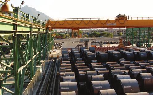

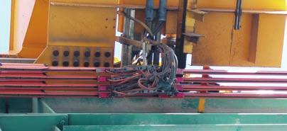


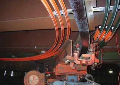
39 Conductor Bar In Action Check out our full line of rugged, dependable, Mobile Electrification Products 107
 1 46 88 15 13 Fax: +33 (0) 1 46 88 15 10 conductix@delachaux.fr www.")
40 CONDUCTIX Worldwide HEADQUARTERS DELACHAUX S.A 119 Avenue Louis Roche - BP Gennevilliers Cedex FRANCE Tel: +33 (0) Fax: +33 (0) delachomgt@delachaux.fr CONDUCTIX OPERATIONS 119 Avenue Louis Roche - BP Gennevilliers Cedex FRANCE Tel: +33 (0) Fax: +33 (0) conductix@delachaux.fr AUSTRALIA CONDUCTIX Pty. Ltd. (Insul-8) Dandenong Tel: +(61) Fax: +(61) info@conductix.com.au BENELUX CONDUCTIX Benelux Brussels Tel: +(32) (0) Fax: +(32) (0) info@conductix.be CANADA CONDUCTIX Corp. (Insul-8) St Jerome Tel: (450) Fax: (450) infocanada@conductix.us CHINA CONDUCTIX Ltd (Han-Fa) Wuhan Tel: +(86) Fax: +(86) info@conductix.cn FRANCE CONDUCTIX (Delachaux) Belley Tel: +(33) (0) Fax: +(33) (0) infoconductix@conductix.fr Gennevilliers Tel: +(33) (0) Fax: +(33) (0) infoconductix@conductix.fr GERMANY / AUSTRIA CONDUCTIX GmbH Offenbach / Main Tel: +(49) Fax: +(49) info@conductix.de ITALY CONDUCTIX Srl (Comes) Milan Tel: +39 (0) Fax: +39 (0) Turin Tel: +39 (0) Fax: +39 (0) info@conductix.it MEXICO CONDUCTIX S.de R.L. de C.V. (Insul-8) Monterrey Tel: +(52) Fax: +(52) infomexico@conductix.us SOUTHEAST ASIA CONDUCTIX Singapore Singapore Tel: +(65) Fax: +(65) info@conductix.com.sg UNITED KINGDOM CONDUCTIX Ltd (Insul-8) Salford Tel: +(44) Fax: +(44) info@conductix.co.uk UNITED STATES CONDUCTIX, Inc. (Insul-8) Omaha, NE Tel: +(1) (1) Fax: +(1) (1) info@conductix.us Harlan, IA Tel: + (1) Fax: + (1) info@conductix.us Picture Credit - Cover: c Digital Vision Countries where we are also represented: Algeria, Argentina, Austria, Bahrain, Bolivia, Brazil, Bulgaria, Cameroon, Chile, China, Colombia, Congo, Ivory Coast, Croatia, Czech Republic, Denmark, U.A.E., Ecuador, Egypt, Finland, Gabon, Greece, Guatemala, Guinea, Honduras, Hungary, Indonesia, India, Iraq, Iran, Ireland, Israel, Japan, Jordan, Korea, Kuwait, Lebanon, Madagascar, Malaysia, Mali, Mauritania, Mexico, Morocco, Netherlands, New Zealand, Niger, Nigeria, Norway, Pakistan, Panama, Paraguay, Peru, Philippines, Poland, Portugal, Romania, Russia, Saudi Arabia, Senegal, Slovakia, South Africa, Spain, Sweden, Switzerland, Syria, Thailand, Taiwan, Tunisia, Turkey, Uruguay, Venezuela, Vietnam... CAT
Conductor Bar. 8 Bar Side Contact
 Conductor Bar 8 Bar Side Contact Contents Conductor Bar Summary Chart 3 Quick Quote Software 4 Comparison of 8 Bar and Safe-Lec 2 5 Quotations Data Sheet 6-7 Insul 8 8 Bar and Side Contact Overview 8 8
Conductor Bar Hevi-Bar II
 Conductor Bar Hevi-Bar II Contents Hevi-Bar II Overview 3 Conductor Bar Summary Chart 4 Quotations Data Sheet 6-7 Hevi-Bar II Features 8 DURA-COAT Corrosion Protection 8 Typical 4-Bar System 9 Hevi-Bar
Conductor Bar Safe-Lec 2 Hevi-Bar II
 Conductor Bar Safe-Lec 2 Hevi-Bar II Contents Safe-Lec 2 and Hevi-Bar II Overview 3 Conductor Bar Summary Chart 4 Quick Quote Software 5 Quotations Data Sheet 6-7 Safe-Lec 2 8-33 Safe-Lec 2 System Components
Conductor Bar Safe-Lec 2 Hevi-Bar II
 Conductor Bar Safe-Lec 2 Hevi-Bar II Contents 2 Safe-Lec 2 and Hevi-Bar II Overview 3 Conductor Bar Summary Chart 4 Quick Quote Software 5 Quotations Data Sheet 6-7 Safe-Lec 2 8-33 Safe-Lec 2 System Components
Conductor Bar Safe-Lec 2 Hevi-Bar II
 Conductor Bar Safe-Lec 2 Hevi-Bar II Contents Safe-Lec 2 and Hevi-Bar II Overview 3 Conductor Bar Summary Chart 4 Quick Quote Software 5 Quotations Data Sheet 6-7 Safe-Lec 2 8-33 Safe-Lec 2 System Components
Cluster Bar. Conductor Bar Systems. Insul-8 Mobile Electrification. For the Electrification of: Solutions From A Single Source
 Insul-8 Mobile Electrification Cable & Hose Reels Conductor Bar Festoon Pendants Radio Controls Slip Rings Solutions From A Single Source Cluster Bar Conductor Bar Systems For the Electrification of: Cranes
DUCT-O-BAR HD Series Conductor Systems 500, 1000 & 1500 Ampere Sizes
 DUCT-O-BAR HD Series Conductor Systems 500, 1000 & 1500 Ampere Sizes A high amperage system of heavy duty conductor bars for large cranes and mobile equipment where strength, reliability and safety are
Conductor Bar Selection
 U L LISTED File # E29805 Contr. 678L Approved in Canada Conductor Bar Selection Determining Ampere Load The conductor selected must be large enough to carry the necessary ampere load safely without undue
Cable Festoon Systems - For Moving Machinery
 Cable Festoon Systems - For Moving Machinery CONDUCTIX offers a comprehensive range of Cable Festoon Systems to power moving machinery. Our festoon systems are ideal for supporting, protecting, and managing
Cable Festoon Systems - For Moving Machinery
 Cable Festoon Systems - For Moving Machinery CONDUCTIX offers a comprehensive range of Cable Festoon Systems to power moving machinery. Our festoon systems are ideal for supporting, protecting, and managing
Series T is Ideal for:
 Series T SAF-T-BAR Series T is Ideal for: Light Rail Systems Automated Storage and Retrieval Systems Conveyors Indoor, Dry Locations Small cranes, monorails, hoists Moving cameras and instruments Other
Hevi-Bar. Conductor Bar Systems. Insul-8 Mobile Electrification. For the Electrification of. Solutions From A Single Source
 Insul-8 Mobile Electrification Cable & Hose Reels Conductor Bar Festoon Pendants Radio Controls Slip Rings Solutions From A Single Source Hevi-Bar Conductor Bar Systems For the Electrification of Cranes
Cable Festoon Systems. C-Track Stretch Wire Rope
 Cable Festoon Systems C-Track Stretch Wire Rope Contents OVERVIEW 3 Festoon Specification Data Sheets 4-5 "Quick Quote Web" Software 6 C-Track Festoon Configurations 7 Flat Cable and Connectors PVC Flat
DUCT-O-BAR Figure 8 Electrical Conductor Systems
 DUCT-O-BAR Figure 8 Electrical Conductor Systems For Overhead Cranes, Trolleys, Monorails, Hoists, Conveyors, Automatic Stacker-Retrieval Systems... any Application that Requires a Reliable, Safe, and
Electromotive Systems ELECTROBAR 8-Bar Conductor Bar System
 Electromotive Systems ELECTROBAR 8-Bar Conductor Bar System ELECTROMOTIVE SYSTEMS ELECTROBAR 8-BAR CONDUCTOR BAR SYSTEMS The practical, proven and economical way to deliver electricity to overhead cranes,
QuickBridge TM. Modern Overhead Crane Bridge Electrification
 QuickBridge TM Modern Overhead Crane Bridge Electrification Features and Benefits QuickBridge TM is a new concept in bridge electrification to give your overhead cranes a clean, contemporary look. QuickBridge
Overhead Crane Specification prepared by SVEDA CRANES SPECIFICATION. * (Top/Under) running * (single/double) girder crane
 running * (single/double) girder crane") SPECIFICATION * (Top/Under) running * (single/double) girder crane 1. SCOPE Crane vendor to provide a complete *-ton capacity * running * girder crane 2. REFERENCE DRAWING (Drawing number and description)
SPECIFICATION * (Top/Under) running * (single/double) girder crane 1. SCOPE Crane vendor to provide a complete *-ton capacity * running * girder crane 2. REFERENCE DRAWING (Drawing number and description)
Electromotive Systems ELECTROBAR ELITE Conductor Bar System
 Electromotive Systems ELECTROBAR ELITE Conductor Bar System ELECTROMOTIVE SYSTEMS ELECTROBAR ELITE ENCLOSED CONDUCTOR BAR SYSTEMS Magnetek s Electromotive Systems division proudly offers ELECTROBAR Elite,
Welded Cap Conductor Rail. for 3rd Rail Mass Transit Systems
 Welded Cap Conductor Rail for 3rd Rail Mass Transit Systems Aluminum-Stainless The Global Solution Aluminum-Stainless Steel Power DID YOU KNOW? 2 There are over 3000 miles (5000km) of AL/SS The World's
Energy Supply Systems
 Energy Supply Systems MULTIPOLE CONDUCTOR RAIL 831 10-125 amps KAT0831-0001b-E 13 pole multipole conductor rail in 33 package distribution centres of the postal service (Post AG) 9 pole multipole conductor
Multipole Conductor Rail MultiLine Program 0831
 Multipole Conductor Rail MultiLine Program 0831 Contents Description / Technical Data Description....2 Technical Data....3 Conductor Rails Rails complete with pre-mounted Connector...4 Power Feeds....5
recognized as the best in the industry for over 115 years. Each component is designed with greater innovation and manufactured with higher
 0-0_q_K //0 : PM Page C R A N E C O M P O N E N T S TM TM THERE S A CRANE SOURCE COMPONENT FOR EVERY JOB. CraneSource crane bridge components have been recognized as the best in the industry for over years.
WORK STATION BRIDGE CRANES
 FREE STANDING WORK STATION BRIDGE CRANES CAPACITIES: SPANS: ENCLOSED TRACKS: PRODUCTIVITY: Up to 4000 lbs Up to 30' Steel, Aluminum & Stainless Steel Average 28% Increase A Class Above... In Productivity.
4 pole insulated conductor rails UNILIFT-ULA 35A, 50A, 80A, 100A
 2 Table of contents General information... 4 Elements of the conductor rail supply line... 4 Innovative connection method... 5 Technical properties... 6 Construction of the line section... 6 Line section...
Interlocks 200 Series
 rd 12070 43 St. NE, St. Michael, MN 55376 763-497-7000 www.tcamerican.com sales@tcamerican.com Installation Instructions Interlocks 200 Series 2I-515; 2I-930 2I-513; 2I-850 Crane Interlock and Operating
Heavy-Duty Conductor Rail CopperHead
 Heavy-Duty Conductor Rail CopperHead Table of Contents CopperHead Conductor Systems 4 Heavy-Duty Conductor Rails...4 Some Advantages of CopperHead Rail Systems...4 Product Pre-Selection...4 Technical
Interlocks 325 Series
 rd 12070 43 St. NE, St. Michael, MN 55376 763-497-7000 www.tcamerican.com sales@tcamerican.com Installation Instructions Interlocks 325 Series 3I-615; 3I-430 3I-613; 3I-450 Crane Interlock and Operating
Saf-T-Bar Conductor Bar T Series
 Saf-T-Bar Conductor Bar T Series P/N 964001 2012.04.12 Rev. 6 SERIES T SAF-T-BAR CONDUCTOR BAR 1 Conductix Incorporated The technical data and images which appear in this manual are for informational purposes
ACI Hoist & Crane. Festoon System. 689 S.W. 7th Terrace Dania, FL (954) Fax (954) Toll Free A-HOIST ( )
 Fax (954) Toll Free A-HOIST ( )") ACI Hoist & Crane Festoon System 689 S.W. 7th Terrace Dania, FL 33004 (954) 921-1171 Fax (954) 921-7117 Toll Free 1-888-4-A-HOIST (1-888-424-6478) www.acihoist.com 2 Standard Duty C-Track Index 1. General
ACI Hoist & Crane Festoon System 689 S.W. 7th Terrace Dania, FL 33004 (954) 921-1171 Fax (954) 921-7117 Toll Free 1-888-4-A-HOIST (1-888-424-6478) www.acihoist.com 2 Standard Duty C-Track Index 1. General
Product Overview Festoon-Systems for I-Beams
 Product Overview Festoon-Systems for I-Beams 2 Conductix-Wampfler Festoon-Systems Count on it! On the go! Cable trolley system program 0350 on a steel mill overhead bridge crane We move your business:
ELECTRONIC OVERHEAD TRAVELLING CRANE DIMENSIONS & LOAD DATA
 ELECTRONIC OVERHEAD TRAVELLING CRANE DIMENSIONS & LOAD DATA FOR ESTIMATING PURPOSES ONLY CONTENTS TOP RUNNING SINGLE GIRDER CRANES 2, 3 & 5 Ton 7.5 & 10 Ton PAGE 2-5 TOP RUNNING DOUBLE GIRDER CRANES 5,
Energy Supply Systems
 Energy Supply Systems SINGLE POLE INSULATED CONDUCTOR RAIL 815 100 amps KAT0815-0001b-E Conductor rail system in a high bay storage Slip ring with conductor rail system in a stretch-foil packing machine
SPACEMASTER WIRE ROPE HOISTS
 SPACEMASTER WIRE ROPE HOISTS The Spacemaster SX represents an innovative design that includes a large drum diameter giving Spacemaster SX hoists the lowest headroom and best wheel loads in the industry
Dearborn Overhead Crane
 A Class Above... In Productivity. In Safety. In Ease of Positioning and Movement. In Ease of Installation. In Designs, Capacities, and Spans. It s no wonder more and more businesses like yours are choosing
Product Overview Conductor Rails
 Product Overview Conductor Rails The simple solution! SingleFlexLine 0811 on an electrified monorail system in a brewery Insulated conductor rails are one of the most widely used systems for the transmission
CEILING MOUNTED WORK STATION BRIDGE CRANES & MONORAILS
 CEILING MOUNTED WORK STATION BRIDGE CRANES & MONORAILS CAPACITIES: SPANS: ENCLOSED TRACKS: PRODUCTIVITY: Up to lbs Up to 0', Aluminum & Stainless Average 28% increase A Class Above... In Productivity.
Stearns Heavy Duty Clutches & Brakes... Rugged, Reliable
 Stearns Heavy Duty Clutches & Brakes... Rugged, Reliable Stearns heavy duty clutches and brakes represent over 75 years of design, engineering and on-the-job experience. Stearns products are backed by
M T E C o r p o r a t i o n. dv/dt Filter. Series A VAC USER MANUAL PART NO. INSTR REL MTE Corporation
 M T E C o r p o r a t i o n dv/dt Filter Series A 440-600 VAC USER MANUAL PART NO. INSTR - 019 REL. 041119 2004 MTE Corporation IMPORTANT USER INFORMATION NOTICE The MTE Corporation dv/dt Filter is designed
SPACEMASTER WIRE ROPE HOISTS
 SPACEMASTER WIRE ROPE HOISTS The Spacemaster SX represents an innovative design that includes a large drum diameter giving Spacemaster SX hoists the lowest headroom and best wheel loads in the industry
1 Product Description System Layout Safety Instructions Intended Use Installation... 3
 Part Number 0812xx- Contents 1 Product Description... 2 2 System Layout... 2 3 Safety Instructions... 3 4 Intended Use... 3 5 Installation... 3 5.1 Hanger Clamp... 3 5.2 Cutting of Conductor Rail... 4
VAHLE MOTOR POWERED CABLE REELS
 VAHLE MOTOR POWERED CABLE REELS INDEX Page Introduction 2, 3 Cable selection 4 Typical applications 5 Questionnaire 6, 7 Model explanation 8 36 Reel selection charts monospiral wrap, horizontal payout
Industrial Control Transformers
 6 Industrial Control Transformers Section 6 Industrial Control Transformers provide a low and safe control voltage for the operation of electromagnetic devices, such as motor starters, contactors, solenoids
M T E C o r p o r a t i o n MATRIX FILTER. SERIES B Volts, 50HZ USER MANUAL PART NO. INSTR REL MTE Corporation
 M T E C o r p o r a t i o n MATRIX FILTER SERIES B 380-415 Volts, 50HZ USER MANUAL PART NO. INSTR - 015 REL. 060628 2006 MTE Corporation IMPORTANT USER INFORMATION NOTICE The MTE Corporation Matrix Filter
Multipole Conductor Rail MultiLine Program 0831
 Multipole Conductor Rail MultiLine Program 0831 ProShell - the modular carrier profile as a system supplement for program 0812 and 0831 ProShell catalog KAT0800-0003-E available for download at www.conductix.com
Product Overview I-Beam Festoon Systems
 Product Overview I-Beam Festoon Systems Count on it! On the go! Program 0350 cable trolley system on a steel mill overhead bridge crane We move your business: where ever materials are being handled, you
Magnetek ELECTROBAR FINGER SAFE (FS) Conductor Bar System
 Conductor Bar System") Magnetek ELECTROBAR FINGER SAFE (FS) Conductor Bar System ELECTROMOTIVE SYSTEMS ELECTROBAR FINGER SAFE (FS) CONDUCTOR BAR SYSTEM Magnetek knows the safety and performance of your overhead material handling
Magnetek ELECTROBAR FINGER SAFE (FS) Conductor Bar System ELECTROMOTIVE SYSTEMS ELECTROBAR FINGER SAFE (FS) CONDUCTOR BAR SYSTEM Magnetek knows the safety and performance of your overhead material handling
Arktite Heavy Duty Circuit Breaking Plugs and Receptacles
 1P Arktite Heavy Duty Circuit Breaking s and Receptacles Industrial Heavy Duty Non-Hazardous Areas Application: Arktite circuit breaking plugs and receptacles are used: to supply power to portable electrically
Design Standard. Purpose: Design Standard:
 Design Standard Purpose: This design standard has the purpose of creating a consistent application of motor-control centers throughout the East Side Union High School District, therefore achieving a standard
Electromotive Systems ELECTROBAR FS Conductor Bar System
 Electromotive Systems ELECTROBAR FS Conductor Bar System ELECTROMOTIVE SYSTEMS ELECTROBAR FS CONDUCTOR BAR SYSTEM Magnetek knows the safety and performance of your overhead material handling system are
Mill Duty Electrification Systems
 Mill Duty Electrification Systems Mission-critical mill equipment must not go down..... Electrification Solutions from Conductix-Wampfler can help! Introduction Mill Duty Electrification In modern iron
Arktite Heavy Duty Circuit Breaking Plugs and Receptacles Industrial Heavy Duty Non-Hazardous Areas
 1P Arktite Heavy Duty Circuit Breaking s and s Industrial Heavy Duty Non-Hazardous Areas Application: Arktite circuit breaking plugs and receptacles are used: to supply power to portable electrically operated
EZTray. Cable Management Made Easy
 EZTray Cable Management Made Easy PRESENTATION Introduction:.................................. 3 EZ Tray: The Tray That Saves You Time!.............. 4-5 EZ Tray: The Innovative Cable Management Solution....
1 Product Description System Layout Safety Instructions Intended Use Installation... 3
 Order Number 0812xx- Contents 1 Product Description... 2 2 System Layout... 2 3 Safety Instructions... 3 4 Intended Use... 3 5 Installation... 3 5.1 Hanger Clamp... 3 5.2 Cutting of Conductor Rail... 4
A. Submit manufacturer's literature and technical data before starting work.
 SECTION 16425 SWITCHBOARD PART 1 GENERAL 1.01 SUMMARY A. Related Section: 1. 16450 - Grounding. 1.02 SUBMITTALS A. Submit manufacturer's literature and technical data before starting work. B. Submit Shop
Saf-T-Bar Conductor Bar H Series
 Saf-T-Bar Conductor Bar H Series P/N 968801 2012.04.24 Rev. 6 SERIES H SAF-T-BAR CONDUCTOR BAR 1 Conductix Incorporated The technical data and images which appear in this manual are for informational purposes
Mipco Connections for Refrigerated Containers. No One Does It Like Mipco. The Mipco. Advantage. Reliability. Safety. Easy Installation & Service
 No One Does It Like Mipco Mipco Interlocked Reefer Power Outlets are used extensively in port terminals and shipboard applications to provide a safe, watertight electrical connection for refrigerated containers.
Understanding NEMA Motor Nameplates
 Understanding NEMA Motor Nameplates Mission Statement is to be the best (as determined by our customers) marketers, designers and manufacturers of industrial electric motors, mechanical power transmission
Solar Combiner Solutions
 Combiner Solutions Built to UL1741 standards NEMA 4X (fiberglass and stainless steel) NEMA 3R (painted steel) Made in America Combiners and disconnects that offer superior resistance and durability from
M T E C o r p o r a t i o n MATRIX FILTER. SERIES B Volts, 50HZ USER MANUAL PART NO. INSTR REL MTE Corporation
 M T E C o r p o r a t i o n MATRIX FILTER SERIES B 380-415 Volts, 50HZ USER MANUAL PART NO. INSTR - 015 REL. 040709 2003 MTE Corporation IMPORTANT USER INFORMATION NOTICE The MTE Corporation Matrix Filter
REFERENCE MANUAL FORM: MX-TRM-E REL REV MTE
 Matrix APAX 380V-415V 50Hz TECHNICAL REFERENCE MANUAL FORM: MX-TRM-E REL. September 2014 REV. 002 2014 MTE Corporation WARNING High Voltage! Only a qualified electrician can carry out the electrical installation
MTE SERIES RLW. World REACTORS USER MANUAL PART NO. INSTR 030 REL MTE Corporation
 MTE SERIES RLW World REACTORS USER MANUAL PART NO. INSTR 030 REL. 090529 2009 MTE Corporation IMPORTANT USER INFORMATION NOTICE MTE Series RLW Line/Load Reactors are components designed to improve the
Insulated Conductor Rail SinglePowerLine Program 0812
 Insulated Conductor Rail SinglePowerLine Program 0812 Table of Contents System Description 5 Technical Data 6 General Instructions 7 System Structure 8 Components and their use....8 Insulated Conductor
CSDA Best Practice. Hi-Cycle Concrete Cutting Equipment. Effective Date: Oct 1, 2010 Revised Date:
 CSDA Best Practice Title: Hi-Cycle Concrete Cutting Equipment Issue No: CSDA-BP-010 : Oct 1, 2010 Revised : Introduction Hi-cycle/high frequency concrete cutting equipment has become more prevalent in
BUILT WITH INTEGRITY
 WITH INTEGRITY Let us share our wealth of knowledge accumulated over three decades. We have equipped the material handling industry across North America with some of the most resilient cranes and crane
4 pole insulated conductor rails ULA 35A, 50A, 80A, 100A
 Table of contents General information... 3 Elements of the conductor rail supply line... 3 Innovative connection method... 3 Technical properties... Construction of the line section... Line section...
4 pole insulated conductor rails ULA 35A, 50A, 80A, 100A
 Table of contents General information... 3 Elements of the conductor rail supply line... 3 Innovative connection method... 3 Technical properties... Construction of the line section... Line section...
Bolted, snap-in and guarter turn type hangers are available. Standard support distance for U12 is 600mm, in curves 300mm.
 General Komay insulated conductors U12 are designed in accordance with today s international safety requirements. The shroud which envelopes the various conductors is an excellent insulator. Therefore
4 Pole / 5 Pole Enclosed Conductor System
 4 / 5 Pole Conductor System 4 Pole / 5 Pole Enclosed Conductor System Enclosed Conductor system with IP23 Finger proof cellular profile. Available in intensities from 20 Amp 200 Amp Data sheet ref : 10
MOTIV- 8 FLEXIBLE CABLE SYSTEMS. www. James Crane.com.au PH:
 MOTIV- 8 FLEXIBLE SYSTEMS www. James Crane.com.au PH: 1300 780 420 Email: Robert@jamescrane.com.au CONTENTS System Selection Enquiry Sheet Carrying Capacity kg Recommended Maximum Speed (m/min) Wire Rope
THE BEST MOVES IN THE WORLD
 THE BEST MOVES IN THE WORLD UNDERHUNG & TOP RUNNING CRANES STACKER CRANE SYSTEMS MONORAILS `SPECIALIZED AVIATION MAINTENANCE CRANES SPECIALIZED LAUNDRY & OVERHEAD MATERIALS HANDLING THE RIGHT MOVE TC/American
Arktite Heavy Duty Circuit Breaking Plugs and Connectors
 Arktite Heavy Duty Circuit Breaking Plugs and Connectors 60 A, 600 VAC/250 VDC, 50**-400 hertz Dimensions Page 968 1P Plug Connector Mating APJ Plugs Mating APR Connectors Style 1 Description Cat. # Dia.
Power-Limiting Cables
 Power-Limiting Cables This section provides general design guidelines for power-limiting heat-tracing systems installed on insulated metal pipes. For other applications or design assistance, contact your
Product Line Glossary Terms
 PURPOSE This document defines terminology used across all of Harrington s Product Lines. SCOPE These definitions will include the following Product Lines: Manual Electric Air Wire Rope Cranes BACKGROUND
EASY CONNECT CRANE KIT Festoon Conductor Systems
 ASSEMBLY INSTRUCTION MANUAL EASY CONNECT CRANE KIT Festoon Conductor Systems October, 2005 Copyright 2005, Yale Lift-Tech, division of Columbus McKinnon Corporation Part No. 117463-05 Mounting Instructions
Matrix APAX. 380V-415V 50Hz TECHNICAL REFERENCE MANUAL
 Matrix APAX 380V-415V 50Hz TECHNICAL REFERENCE MANUAL WARNING High Voltage! Only a qualified electrician can carry out the electrical installation of this filter. Quick Reference ❶ Performance Data Pages
NATURAL HIGH IMPACT STRENGTH COPPER FREE ALUMINUM Number of Wires VAC AT 50 TO 400 HZ/250 VDC
 3804 South Street 75964-7263, TX Nacogdoches Phone: 936-569-7941 Fax: 936-560-4685 AllenWatson@elliottelectric.com AR331 30 Amp Pin & Sleeve Recpt 3-W 3-P 250VDC/600vac Cooper Crouse-Hinds Catalog Number
Demag DH hoist units. The solution to meet special requirements
 Demag DH hoist units The solution to meet special requirements 1 Demag DH hoist units for solutions beyond classic crane applications Synchronised DH hoist units lift and lower a roof segment in a shopping
Collectors. Current Collecting Components/Collectors. Collector Designs for all Applications. Many different Collector Interface Materials & Styles
 Collectors Current Collecting Components/Collectors Collector Designs for all Applications Many different Collector Interface Materials & Styles Rigid Conductor Bar Collectors Pick up Wire Collector Designs
Taxonomies, Classifications, and Categories CIRCUIT BREAKING, COMPRESSOR, CONVEYOR, MOTOR GENERATOR SET, POLARIZED, WELDER
 3804 South Street 75964-7263, TX Nacogdoches Phone: 936-569-7941 Fax: 936-560-4685 AP20467S22 3W-4P 200A Plug Cooper Crouse-Hinds Catalog Number AP20467S22 Manufacturer Cooper Crouse-Hinds Description
SURFACE TRACK (120/250V) SPECIFICATIONS
 SPECIFICATIONS") SURFACE TRACK (120/250V) SPECIFICATIONS GENERAL Lighting Track shall allow fixtures to be located anywhere along the track length. Fixtures shall be easily focused, switched, dimmed, accessorized and removed
SURFACE TRACK (120/250V) SPECIFICATIONS GENERAL Lighting Track shall allow fixtures to be located anywhere along the track length. Fixtures shall be easily focused, switched, dimmed, accessorized and removed
Electrobar FS Conductor Bar System
 Electrobar FS Conductor Bar System Electromotive Part Number: 005-1066 R12 Copyright 2015 Magnetek Material Handling Table of Contents Chapter 1.0: Danger, Warnings and Cautions... 33 Chapter 2.0: Disconnecting
Data Bulletin. Ground-Censor Ground-Fault Protection System Type GC Class 931
 Data Bulletin 0931DB0101 July 2001 Cedar Rapids, IA, USA Ground-Censor Ground-Fault Protection System Type GC Class 931 09313063 GT Sensor Shunt Trip of Circuit Interrupter Window Area for Conductors GC
POWER BAR SYSTEM ECONOMICAL ENCLOSED CONDUCTOR SYSTEM FOR MOBILE EQUIPMENT M O B I L E E L E C T R I F I C A T I O N
 A e r o B A R POWER BAR SYSTEM ECONOMICAL ENCLOSED CONDUCTOR SYSTEM FOR MOBILE EQUIPMENT M O B I L E E L E C T R I F I C A T I O N AeroBAR Enclosed Conductor Bar System AeroBAR provides many of the advantages
FABA. Standard Components. Conductor Bar System. publication #FABASC-04 1/1/04 Part Number: Copyright 2003 Electromotive Systems
 FABA Conductor Bar System Standard Components publication #FABASC-04 1/1/04 Part Number: 000-2201 Copyright 2003 Electromotive Systems Table of Contents Section IS 100 A - Introduction General Information
Design standards used : CMAA, CSA, AIST, AISE, OSHA, FEM, HMI, CWB, AWS, ANSI, ASME, ASTM, AGMA, NEC, NEMA, IEEE, UL, ISO
 Through innovation and cutting-edge technology, provide sound engineering solutions while improving equipment efficiency, reliability, and safety. Achieve the highest level of customer satisfaction throughout
SECTION ENCLOSED SWITCHES AND CIRCUIT BREAKERS
 SECTION 26 28 16 ENCLOSED SWITCHES AND PART 1 - GENERAL 1.1 SUMMARY A. Section includes the following individually mounted, enclosed switches and circuit breakers rated 600V AC and less: 1. Fusible switches.
10 Commercial, Industrial, Agricultural Services
 10 Commercial, Industrial, Agricultural Services This section describes the Power Company requirements for commercial, industrial, and agricultural services. This section covers single phase and three
Type K Features. Heavy, stainless steel terminals. Average 7652 watts per. single unit. Designed to NEMA resistor standards.
 Hubbell Industrial Controls, Inc. Euclid Power Resistors Euclid Power Resistors Type K and Type HHC 38 to 695 Amperes Catalog & Price List January 2011, Replaces May 2010 Engineered for endurance, the
2.0 CONSTRUCTION AND OPERATION 3.0 CHARACTERISTICS K. CO (HI-LO) Overcurrent Relay
 Overcurrent Relay") 41-100K 2.0 CONSTRUCTION AND OPERATION The type CO relays consist of an overcurrent unit (CO), either an Indicating Switch (ICS) or an ac Auxiliary Switch (ACS) and an Indicating Instantaneous Trip unit
41-100K 2.0 CONSTRUCTION AND OPERATION The type CO relays consist of an overcurrent unit (CO), either an Indicating Switch (ICS) or an ac Auxiliary Switch (ACS) and an Indicating Instantaneous Trip unit
Hoists Polipastos Hebezeuge Palans
 Hoists Polipastos Hebezeuge Palans By Detroit Hoist PAGE 2 Better Cranes Begin with Detroit Hoist At the forefront of hoist technology - US made since 1905 For almost a century Detroit Hoist has designed
FREE STANDING WORK STATION JIB CRANE
 SECTION 14661 FREE STANDING WORK STATION JIB CRANE ***** Gorbel, Inc. manufacturers a broad range of material handling cranes including monorail, bridge, gantry, and jib cranes. Numerous work station and
B CW POWER RELAY
 41-241.31B CW POWER RELAY nected in such a way that current, (I A ), leads voltage, (V BA ), by 150 degrees when the motor is operating at unity power factor. Loss of excitation to the motor causes a large
RECESSED TRACK (120V) SPECIFICATIONS
 SPECIFICATIONS") RECESSED TRACK (120V) SPECIFICATIONS GENERAL Recessed track shall be approved by the NEC for flush-mounting into ceiling or any flat surface. Recessed Track shall allow fixtures to be easily focused, switched,
RECESSED TRACK (120V) SPECIFICATIONS GENERAL Recessed track shall be approved by the NEC for flush-mounting into ceiling or any flat surface. Recessed Track shall allow fixtures to be easily focused, switched,
Harrington Beam Accessory Kits. Options and Accessories: Consult Factory. Compliance
 Harrington Beam Accessory Kits Provides the convenience of pre-fabricated bracing and bridge beam accessories. For use with any Harrington end truck specify end truck model when ordering. Kit includes:
Medium Voltage Standby non-paralleling Control GUIDE FORM SPECIFICATION
 Medium Voltage Standby non-paralleling Control 1. GENERAL GUIDE FORM SPECIFICATION A. The requirements of the contract, Division 1, and part 16 apply to work in this section. 1.01 SECTIONS INCLUDE A. Medium
ALINOX INSULATED CONDUCTOR RAIL FOR ELECTRICAL FEEDING OF CRANES
 ALINOX INSULATED CONDUCTOR RAIL FOR ELECTRICAL FEEDING OF CRANES 2 ALINOX INSULATED CONDUCTOR RAIL Features, advantages and benefit The insulated conductor rail system ALINOX is the most suitable solution
GENERAL INDEX TR60. 6 YELLOW LINE Continuous Conductors. Max 5 Poles. 8 BLUE LINE Pre-Mounted Conductors TR85H5P. YELLOW LINE Continuous Conductors
 2 Automation - Lift - Handling System GENERAL INDEX 2 DESCRIPTION 3 BUSBAR LINE VERSIONS LINE TYPE / AMPERAGE COVERAGE 5 TR60 40 A 50 A 60 A 70 A 100 A 140 A 160 A 200 A 320 A 6 YELLOW LINE Continuous
INTEGRID TRACK (120V) SPECIFICATIONS
 SPECIFICATIONS") INTEGRID TRACK (120V) SPECIFICATIONS GENERAL Integrid Track shall be a combination Track and main runner for mech - anically supporting suspended ceiling systems. Integrid Track shall allow fixtures to
INTEGRID TRACK (120V) SPECIFICATIONS GENERAL Integrid Track shall be a combination Track and main runner for mech - anically supporting suspended ceiling systems. Integrid Track shall allow fixtures to