Installation and operating instructions. Swing gate operator SWING-X
|
|
|
- Aldous Merritt
- 5 years ago
- Views:
Transcription


1 Installation and operating instructions Swing gate operator SWING-X
2 Important warning and safety notes for installation and operation These installation- and operating instructions form an integral part of the product gate operator. They have been specifically written for professional installers trained and skilled in the trade and should be carefully read in their full length before carrying out the installation. They describe the proper installation and operation of the sliding gate operator only, not of the overall device automatic gate. After the installation this manual has to be handed over to the user. Installation, connection, adjustments, putting into operation, and servicing may only be carried out by trained professionals in full accordance with these installation- and operating instructions. The EU Machine Directive, laws and rules concerning the prevention of accidents, and laws and standards which are in force in the EU and in the individual countries have to be strictly followed. The TOUSEK Ges.m.b.H. cannot be held liable for any claims resulting from disregards of the laws and standards in force during the installation and operation. The product may only be used in accordance with its original purpose, for which it has been exclusively designed, and which is described in these installation and operating instructions. The TOUSEK Ges.m.b.H. rejects any liability if the product is used in any way not fully conforming to its original purpose as stated herein. The product is not suitable for installation in explosion-hazardous areas. The existance of inflammable gas and steam is of great danger! The packaging materials (cardboard, plastic, EPS foam parts and filling material etc.) have to be properly disposed of in accordance with the applying recycling- and environmental procection laws. They may be hazardous to children and therefore have to be stored out of children s reach. Before beginning with the installation the installer has to make sure that all mechanical components of the gate facility, like carrier profile/rail, gate frame and panels, guiding elements etc. are sufficiently supportive and resistant for the purpose of gate automation. Check also whether the product has transport damages. All electrical installations have to be made in full conformity with the applying rules and laws (e.g. using a fault current circuit breaker, proper grounding etc.). An all-pole disconnecting main switch with a contact opening-gap of minimum 3 mm has to be foreseen. When installing the safety device (photocells, safety edges, emergency-stops etc.) please comply with the valid direcitves/standards, the criteria of practical rules of conduct, the installation environment, the operating logic of the system and the effected force of the motorised gate.. The safety devices must secure possible bruise, shear and general danger areas of the motorised gate. After installation the proper function of the gate facility and the safety devices has to be checked! Place warning signs and notes of the valid regulations to indicate danger areas. With each installation the identification data of the motorised gate has to be placed in a visible place. The label for the Handauslöser has to be placed next to its operating element. The electric motor heats up during operation. Therefore the device should only be touched after it has cooled off. Please make sure that no other persons are on site of the motorised gate area, especially in when operating the facility in hold to run mode (switch with OFF-pre adjustment). The pre-adjusted OFF-button/switch has to be placed in sight of the actuated gate but away from moving parts. This switch/button (except key-switch) has to be mounted in min.,5m height and non-accessible to the public. Children have to be instructed, that the gate facility as well as the belonging parts may not be used improperly, e.g. for playing. Furthermore handheld transmitters have to be kept in safe places and other impulse emitters as buttons and switches have to be installed out of children s reach. Only original spare- and replacement parts may be used for repair of the product. The TOUSEK Ges.m.b.H. rejects any liability for claims resulting from usage of the product in combination with components or devices which do not fully conform to the applying safety laws and rules. The installer has to inform the user about all aspects of the automatic operation of the complete gate facility, as well as about emergency operation. The installer further has to supply to the user all instructions relating to the safe operation of the gate facility. The installation and operating instructions also have to be handed over to the user. The user has to be informed that he has to turn off the main power switch in case of malfunction of the product and that he can use the facility again after repair and adjustment works have been completed. Please notice that the warranty will not be applicable if the label with the engine number has been removed or damaged. Maintenance Disconnect the power supply during mounting, maintenance and repair works. Maintenance works may only be carried out by qualified personnel. Check the proper force adjustment once a month. Check the proper function of the emergency release mechanism periodically. Check if all mounting screws are securely fastened periodically. Remove dirt from the operator periodically. Maintenance and servicing of the complete gate facility has to be carried out according to the gate builder s/ installer s instructions. EU - Manufacturer s Declaration according to Machine Directive 006/4/EC: The company TOUSEK Ges.m.b.H., based in Zetschegasse, A-30 Vienna/Austria, hereby declares that the swing gate operator SWING X is made available only for the purpose of being built into a machine or being joined with other machines or machine components, and that it may not be put into operation until a declaration of conformity according to the Directive 006/4/EC has been issued for the whole machine. The following directives and standards have been applied: - Low Voltage Directive 006/95/EC, incl. changes - Electromagnetic Compatibility Directive 004/08/EC, incl. changes January 0 This manual is the sole property of the TOUSEK Ges.m.b.H. and may not be made available to competitors. All rights reserved. No part of it may be reproduced without our prior written permission. We will not accept liability for any claims resulting from misprints or errors. This edition of the manual replaces all earlier publications of the same. - - tousek / E_SWING-X_ /
 self-locking gear mechanism high-grade bronze worm wheel emergency release lockable with standard half cylinder torque sensor adjustable internal limit stops (mechanical) adjustable")
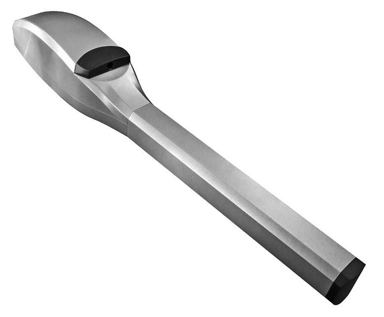
3 . General Swing gate operator SWING-X Characteristics electromechanical swing gate operator for 30V a.c. gate weight max. 500kg (per wing) self-locking gear mechanism high-grade bronze worm wheel emergency release lockable with standard half cylinder torque sensor adjustable internal limit stops (mechanical) adjustable soft stop automatic reverse system ARS suitable for subsequent installation elegant design General features The swing gate operator TOUSEK SWING X, can be easily installed at new and also already existing swing gate facilities For the development of the SWING X electromechanic operator the main objective was set upon reliability and long durability. For this reason all parts are made of premium materials such as aluminium, stainless or galvanised steel. Also the whole gearing which is placed in a diecast aluminium housing as well as the drive unit are entirely made of metal. This ensures long lasting trouble-free operation. The drive/operator is gimbal-mounted on both gate and column side. This enables an absolutely free of play installation of the operator as well as smooth and even movement of the gate. An extremely massive spindle together with a spindle socket made of brass ensures a long lasting and reliable operation. Of course the spindle is supported on both sides. This prevents unwanted vibrations. A torque sensor enables the use of the automatic reverse system (ARS). When touching an obstacle the operator stops and reverses automatically. This guarantees a high degree of safety. the operator closes the gate reliably. The emergency release which is important in case of power failure is lockable with a standard profile half cylinder. It can therefore be replaced and integrated into an already existing house key system. The cylinder and 3 keys are included as standard equipment. The operators ensure the blocking of the gate and therefore usually do not need the use of electric locks. To obtain a fixed detention of the gate in the end positions it can also be useful for blocking gate operators - according to the installation- to install an additional locking device such as e.g. a electronic lock. In order to avoid a limit stop on the floor - which can be dangerous and annoying - the operator has a built-in mechanical limit stop. Technical data Swing gate operator SWING- X3/ X3/LH X4/ X4/LH X5/LH X3/ X3/LH X4/ X4/LH X5/LH Power supply 30Va.c., 50Hz Motor condensator 0µF Max. wing width 3m 4m 4,5m 5m max. stroke 30mm 450mm 30mm 450mm Max. wing weight 500kg travel speed 4mm/s mm/s Operating factor (mode S3) 40% Thrust 4000N 5000N 6500N Ambient temperature -0 bis +40 C Article no Other blocking in open and closed position force adjustment through control unit emergency release lockable through standard half cylinder adjustable Anschläge torque sensor optional: boltable motor attachment brackets for gate and column (galvanised or stainless steel) Note: Max. wing widths do neither apply to full-panel gates (but to stave or trellised gates) nor to non-horizontal gates tousek / E_SWING-X_ /

4 . Installation Swing gate operator SWING-X General installation notes The operator type SWING X is equipped with internal limit stops that can be used for gates below 00kg and with a wing width below 3m for adjustment of limit positions OPEN and CLOSED. Gates with a weight above 00kg and more than 3m gate width can not be used with the internal limit stops, please use external limit stops (4) for gate limit positions! particularly in the closed position it is recommended to use always a floor limit stop (4) or Tousek piston rod. With lean or wooden gates the welding part should not be mounted directly on the gate. Please use for that a flat steel bar. *) Attention: to avoid contaminations and to ensure a long lasting and reliable operation please make sure to keep a minimum distance of 400mm to the driveway top edge. The mounting points Montagepunkte for the front () and for the rear welding part () should be chosen in accordance of the below mentioned mounting measures. The adjustment/alignment of the operator should be levelled out (please note vertical misalignement (V) of welding parts!). V=65mm min. 400mm gate column left gate wing driveway top edge left gate wing INSIDE right gate wing 4 4 a. Definition of mounting points and attachment of welding parts Installation Mounting points Note The mounting points for the front () and for the rear welding part () should be chosen in accordance of the mounting measures (see following tables). Please note that the measures A, B and D must always be measured from the pivotal point of the gate. Furthermore a vertical has to be placed for a levelled adjustment of operator (V=65mm) between the welding parts tousek / E_SWING-X_ /
5 Mounting measures with different swing gate situations Note The specified measures correspond only to the pictured gate types pivotal point centered with max. leaf thickness of 60mm or pivotal point not centered, to the inside. For differing gate types please find out the corresponding measures! Opening to the INSIDE (pivotal point centered to gate leaf) B max. 60mm Opening to the INSIDE (pivotal point not centered (inside) to gate leaf) B A D A D C INSIDE C INSIDE Mounting measures SWING X3 opening to the INSIDE SWING X3/ (standard stroke) Application standard standard SWING X3/LH (long stroke) for larger columns for larger opening angle A (mm) B (mm) C (mm) D (mm) max. opening angle max. wing width 3m 3m 3m 3m Mounting measures SWING X4, X5 opening to the INSIDE SWING X4/ (standard stroke) SWING X4/LH + SWING X5/LH (long stroke) Application standard for larger opening angle standard for larger columns for larger opening angle A (mm) B (mm) C (mm) D (mm) max. opening angle max. wing width 4m 3,5m X4/LH: 4,5m X5/LH: 5m 4m 4m Mounting at larger columns B Important A C D INSIDE For keeping the measurements A and B, at larger columns an alcove according to the beside picture has to be made. The recess in the gate column has to be big enough to make sure that the electrical supply cable of the operator will not be buckled. tousek / E_SWING-X_ /
6 Special case: opening to the OUTSIDE B OUTSIDE max. 60mm A D C Mounting measures opening to the OUTSIDE SWING X3/ (standard stroke) SWING X4/ (standard stroke) SWING X4/LH + SWING X5/LH (long stroke) Application standard standard standard A (mm) B (mm) C (mm) D (mm) max. opening angle max. wing width 3m 4m X4/LH: 4,5m X5/LH: 5m Mounting of welding parts Mounting of rear welding part after having defined the pivotal point (taking into account the mounting measures) attach the rear welding part () in that position to the gate column (wall) and support it with a gusset plate (3). Mounting of front welding part now attach the front welding part () in compliance with measure C to the gate wing. Attention: please note upper/under side (see figure page 4). Please make sure that the gate is fully closed and that the vertical misalignment V = 65mm between the two welding parts is kept to ensure a levelled mounting of the operator. With lean or wooden gates the welding part should not be mounted directly on the gate. Please use for that a flat steel bar. support the front welding part () with a gusset plate (3) tousek / E_SWING-X_ /

, to ensure the movability on the pivotal point!")
, to ensure the movability on the pivotal point!")

7 b. Installation of the operator Installation After having mounted the welding parts and junction plates(3) please install the operator as follows. Before mounting please note that the moving parts should be lubricated on their pivotal points! Now slide the operator with the fork on the rear welding part (), insert the brazed screw from above, place a plate below and fix with by using the screw nut. the screw nut that has been tigthened before, should now be opened a little (approx. /4 turn), to ensure the movability on the pivotal point! Now turn the gate wing until the bolt/pin of the part (L) (= part which is moved through the operator spindle) can be put from above into the drilling of the front welding part (). Then place a plate below and fix by using the screw nut. the screw nut that has been tigthened just now, should now be opened a little (approx. /4 turn), to ensure the movability on the pivotal point! 3 Lubrication for moving mounting parts 3 The pivotal points of the operators (holes of welding parts and corresponding pins/screws, that are used for the attachment of the operator on the welding parts, have to be lubricated before installation of the operator! c. Adjustment of internal limit stops Installation The operator type SWING X is equipped with internal limit stops that can be used for gates below 00kg and with a wing width below 3m for adjustment of limit positions OPEN and CLOSED. The following steps describe the adjustment for gates opening to the inside (when opening to the outside then the limit stops have exactly the contrary function - (6) for closed and (5) for open position): Unlock the gate (see emergency release ). Manually move the gate with unlocked operator into end position CLOSED. Now move the internal limit stop closed (5)- after dismantling the hexagon head screw- towards the part (L) (on contact!). After that please tighten the hexagon head screw. Now move the gate into OPEN limit position. Now move the internal limit stop open (6)-after dismantling the hexagon head screw - towards the partl (L) (on contact!). After that please tighten the hexagon head screw again. Lock the operator again. Readjustment When operator is ready for operation, place/drive/move the operator with electricity (through an impulse) into limit positions and if necessary readjust the internal limit stops. Before adjusting the operator please disconnect from power supply Important (for gate wing > 00kg or >3m) Gates with a weight over 00kg or with a width above 3m, as described here, can not be used with the internal limit stops, please use external limit stops (4) for gate limit positions! 6 L L 5 tousek / E_SWING-X_ /

 have to be laid separately from the 30V lines (supply line, motors, signal lamp).")

8 d. Electric connections and force adjustment Installation Warning Before carrying out the electrical connections, the power supply of the gate facility must be turned off The safety regulations for electric shock prevention have to be complied. The device should only be connected by qualified personnel The device should not be used in an explosive environment! An all-pole disconnecting mains switch with a contact opening gap of min. 3 mm has to be foreseen. The gate facility has to be secured according to the valid safety regulations! IMPORTANT: The control lines (buttons, radio, photocells, etc.) have to be laid separately from the 30V lines (supply line, motors, signal lamp). The safety standards and regulations regarding the force adjustment have to be in compliance with the effective rules! The gate facility must be turned off from power supply when making the electrical connections. The motor wire (M) and sensor wire (S) have to be connected to the control unit as described in the manual of the control unit. Please note the colours (from motor cable) and the index number 3 (from sensor cable)! For the connection of diverse safety devices, transmitters and other accessories please check the corresponding manuals (please note cable/wire plan). The force adjustment of the operator is made through the control unit (please see manual for control unit). yellow/ green M black blue braun 3 3 S Important The motor and sensor wires have to be supplied to the control unit by two separate lines! The sensor wire must not exceed the max. length of 50m! For the sensor supply line between operator and electronic control make sure that only the 3 electronic control cables are being clamped - do not clamp to a ground wire (earth lead)! e. Dismounting the dismounting of the motor is effected in the opposite order of installation. Please note that before dismounting the operator the power supply has to be turned off! 3. Emergency release of the operator at power failure Swing gate operator SWING X should it be necessary to release the operator (e.g. in case of power failure, please proceed as follows: Turn off power supply of gate facility! Unlock the emergency release lock and turn the emergency release lever to the limit (for 90 ). The operator is now unlocked and the gate may be moved manually (slowly!- not faster than with the operator). For operator usage turn the emergency lever back to its initial position and close the emergency release lock. After that turn on the power supply. After impulse transmission the limit positions (OPEN and CLOSE) are being automatically adjusted tousek / E_SWING-X_ /
 included into the logic control box on the ST -models) 9 antenna (connection to")
9 4. Cable plan swing gate operator SWING X A 8 *) operator Tousek SWING X electronic logic control 3 external fotocell (T: transmitter, R: receiver) 4 internal fotocell (T: transmitter, R: receiver) 5 pushbutton momentary contact switch 6 key-operated momentary contact switch 7 signal light 8 radio remote receiver, *) included into the logic control box on the ST -models) 9 antenna (connection to radio receiver with coaxial cable) 0 main power switch and fuse A Note: An all-pole disconnecting main switch with a contact opening-gap of minimum 3 mm has to be foreseen 7 4x0,75 mm 9 3x mm 3x,5 mm x,5 mm 3x0,75 mm 3R x0,75 mm 4T safety sensing edges electric lock 3 hinged lockiing bar 4 floor stops 5 connection box 4 3 x mm 3T 5 5 x0,75 mm Important The motor and sensor wires have to be supplied to the control unit by two separate lines. The sensor wire must not exceed the max. length of 50m! For the sensor supply line between operator and electronic control make sure that only the 3 electronic control cables are being clamped - do not clamp a ground wire (earth lead)! 4x,5 mm 3x0,75 mm 4R NOTE concerning cable laying The electric cables have to be laid in insulating sleeves which are suitable for underground usage. The insulating sleeves have to be lead into the inner of the operator housing. 30 V cables and control lines have to be laid in separate sleeves. Only double-insulated cables, which are suitable for underground usage (e.g. E-YY-J) may be used. In case that special regulations require another type of cable, cables according to these regulations have to be used. SAFETY NOTE Please be aware that the beside picture is only a symbolic sample illustration of a gate facility and may therefore not show all safety devices required for your specific application. To achieve an optimum safety level at your gate facility, please make sure that all safety components and accessories which - according to the applying safety rules and laws - are required in your particular case (e.g. photocells, induction loops, sensing edges, signal lamps, traffic lights, mains- and emergency power off switches etc.) are properly installed, operated, and serviced. All possible bruise, shear and general danger areas of the motorised gate have to be secured. In this context please follow the EU Machine Directive, accident prevention rules and laws, as well as applying EU- and national standards in force at the time of installation and operation of the gate facility. The Tousek Ges.m.b.H. cannot be held responsible for any consequences resulting from disregard of applying standards and laws during installation or operation of the gate facility. x0,75 mm 4x0,75 mm The 0,75mm control lines are shown without ground lead. In order to facilitate connections we recommend using flexible wires and not using thicker wires for the control lines. tousek / E_SWING-X_ /
 () rear welding part (installation on the gate column - supported by gusset plate!")
: boltable motor attachment bracket Article no. galvanised 4030 stainless steel 4030 68 65 max.")
10 5. Dimensioned sketch Swing gate operator SWING X measures in mm () front welding part (installation on the gate - supported by gusset plate!) () rear welding part (installation on the gate column - supported by gusset plate!) (5) internal limit stop (for position CLOSED with gates opening to the inside) (6) internal limit stop (for position OPEN with gates opening to the inside) (L) running part optional (for mounting on the gate): boltable motor attachment bracket Article no. galvanised 4030 stainless steel max. stroke 30 (SWING-X3/, -X4/) 450 (SWING-X3/LH, -X4/LH, -X5/LH) L (SWING-X3/, -X4/) 070 (SWING-X3/LH, -X4/LH, -X5/LH) optional (for mounting on the column): boltable motor attachment bracket Ø0 Article no. galvanised 4080 stainless steel Ø,5 40,5 47,5 47,5, Ø, 00 Ø5, , V=65 measures and technical modifications subject to change! tousek / E_SWING-X_ /
11 tousek / E_SWING-X_ /

12 tousek PRODUCTS sliding gate operators cantilever systems swing gate operators garage door operators folding door operators traffic barriers carpark management system window operators domelight operators sliding door operators electronic controls radio remote controls key operated switches access control safety devices accessories Tousek Ges.m.b.H. Austria A-30 Vienna Zetschegasse Tel. +43// Fax +43// info@tousek.at Tousek GmbH Germany D Freilassing Traunsteiner Straße Tel. +49/86 54/ Fax +49/86 54/ info@tousek.de Tousek GmbH Switzerland CH-675 Ballwil Bahnhofstraße 4 Tel. +4/0/ Fax +4/0/ info@tousek.ch Tousek Sp. z o.o. Poland PL Mikołów (k/katowic) Gliwicka 67 Tel. +48/3/ Fax +48/3/ info@tousek.pl your service partner: Tousek s.r.o. Czech Republic CZ Praha 3 Jagellonská 9 Tel. +40// Fax +40// info@tousek.cz tousek E_SWING-X_ We reserve the right to change dimensions and/or technical specifications without prior notice. Claims resulting from misprints or errors cannot be accepted.
Installation and operating manual. Swing gate operator SWING 225
 Installation and operating manual Swing gate operator SWING 5 Important warning and safety notes for installation and operation These installation- and operating instructions form an integral part of the
sliding gate opener PULL T5, -T8, -T10, -T15
 Technical information / Planning document tousek PRODUCTS sliding gate opener PULL T5, -T8, -T0, -T5 sliding gate operators cantilever systems swing gate operators garage door operators Fields of application:
PULL T8, -T10, -T15 / Master-Slave
 Technical information / Planning document PULL T8, -T10, -T15 / aster-slave tousek PRODUCTS sliding gate operators sliding gate openers for opposite sliding gates cantilever systems swing gate operators
EC MACHINE DIRECTIVE COMPLIANCE DECLARATION
 770 EC MACHINE DIRECTIVE COMPLIANCE DECLARATION (DIRECTIVE 89/392 EEC, APPENDIX II, PART B) Manufacturer: FAAC S.p.A. Address: Via Benini, 1 40069 - Zola Predosa BOLOGNA - ITALY Hereby declares that: the
EC MACHINE DIRECTIVE COMPLIANCE DECLARATION
 EC MACHINE DIRECTIVE COMPLIANCE DECLARATION (DIRECTIVE 89/392 EEC, APPENDIX II, PART B) Manufacturer: FAAC S.p.A. Address: Via Benini, 1 40069 - Zola Predosa BOLOGNA - ITALY Hereby declares that: the 770
Automation Swing Gate Opener
 Automation Swing Gate Opener Operating and installation instructions SP EIFFEL 400 V1.0 Rev 08/01 CONTENTS 0) GENERAL SAFETY REGULATIONS...Page 0 1) DESCRIPTION...Page 03 ) TECHNICAL SPECIFICATIONS 3)
Porte 150 Users Manual Swing Gate Opener 24V DC
 Porte 150 Users Manual Swing Gate Opener 24V DC for residential use only Signal Light Push-button Control Box 14 Contents 1. Important Safety Information 2. Product Description and Application 2.1 Application
Porte 300 Users Manual Swing Gate Opener 24V DC for residential use only
 Porte 300 Users Manual Swing Gate Opener 24V DC for residential use only Signal Light Push-button Control Box Gate 2 Gate 1 Contents 1. Important Safety Information 2. Product Description and Application
Sliding gate operators TPS 20
 Mounting and installation manual Sliding gate operators TPS 20 Safety Sensor TPS 20 TPS 20N TPS 20 PRO Index General warning and safety details... 3 1. Notes, general characteristics, function, technical
IRREVERSIBLE OPERATOR FOR SWING GATES AND DOORS
 VH IRREVERSIBLE OPERATOR FOR SWING GATES AND DOORS WARNING!! Before installing, thoroughly read this manual that is an integral part of the pack Our products if installed by qualified personnel capable
FEATURES AND SPECIFICATIONS
 FEATURES AND SPECIFICATIONS The is a high quality hydraulic operator for residential and condominium use with leaf length up to 3 m. Available in the following versions: AC (with lock in opening and closing)
Installation manual ASTER AUTOMATION FOR SWING GATES 11_16
 Installation manual ASTER AUTOMATION FOR SWING GATES 11_16 Contents 1. GENERAL SAFETY PRECAUTIONS... page 01 2. INTENDED USE AND APPLICATION... page 01 2.1 Kit contents... page 01 2.2 Technical features...
Sliding gate operators PULL T5, -T8, -T10
 Mounting and installation manual Sliding gate operators PULL T5, -T8, -T10 C O M P A T L E I B Index General warning and safety details... 3 1. Notes, general characteristics, function, technical data...
UNDERGROUND OPERATOR FOR SWINGING GATES. WARNING!! Before installing, thoroughly read this manual that is an integral part of the pack
 UNDERGROUND OPERATOR FOR SWINGING GATES COMPAS 2 WARNING!! Before installing, thoroughly read this manual that is an integral part of the pack Our products if installed by qualified personnel capable to
INSTRUCTIONS FOR INSTALLATION
 HYDRAULIC OPERATOR MODO 110-110/L FOR SINGLE- OR DOUBLE-WING SWING GATES INSTRUCTIONS FOR INSTALLATION GENERAL WARNINGS These warnings constitute an integral and essential part of the product and must
SWING GATE OPENERS 24V DC GEAR MOTOR
 SWING GATE OPENERS 24V DC GEAR MOTOR FOR RESIDENTIAL USER MANUAL Flashing Light Push Button Control box Gate 2 Gate 1 Index 1. Warnings 2 4. Technical Characteristics 16 2. Product Description 2.1 Applications
MASTIFF 300/300M SWING GATE OPENER USER MANUAL
 MASTIFF 300/300M SWING GATE OPENER USER MANUAL INDEX 1.1 GENERAL SAFETY PRECAUTION 1.2 INSTALLATION A. STANDARD INSTALLATION B. DIMENSION CHART C. MOTOR FIXING D. WIRE CONNECTION E. EMERGENCY RELEASE F.
Belt Conveyor Pull Rope Switch Types HEN, HEK and SEM OPERATING INSTRUCTIONS
 Belt Conveyor Pull Rope Switch Types HEN, HEK and SEM OPERATING INSTRUCTIONS 2 CE-Sign and Conformity The device meets the requirements of the valid European and national regulations. Conformity has been
TECHNICAL DATA HYDRAULIC UNIT
 GB INSTRUCTIONS MANUAL RISING BOLLARD OIL-HYDRAULIC AUTOMATION COMPONENTS strabuc 918 RELEASE KEY PLUG FOR RELEASE HOLE BOLLARD COVER 12 V WARNING LIGHTS REFLECTORS COMPLETELY RETRACTABLE POST WITH ELECTROPHORESIS
OPERATING INSTRUCTIONS
 Conveyor Belt Misalignment Switch Type MRS 001 Device Identification No.: 91.055 301.001 OPERATING INSTRUCTIONS 2 CE-Sign and Conformity The device meets the requirements of the valid European and national
PW320/PW330 USER MANUAL SWING GATE OPENERS 24V DC GEAR MOTOR FOR RESIDENTIAL. Flashing Light. Push Button. Control box. Gate 2.
 PW320/PW330 USER MANUAL SWING GATE OPENERS 24V DC GEAR MOTOR FOR RESIDENTIAL Flashing Light Push Button Control box Gate 2 Gate 1 Declaration of Conformity Applicant: Powertech Electronics Inc. Manufacturer:
Ordering designation: G(Type) - (Stroke) - (Eye bolt) - (Cable length) - (Options) Legend:
 - (Stroke) - (Eye bolt) - (Cable length) - (Options) Legend:") General technical data: 1.) Anodised aluminium housing with a connecting rod made of aluminium (in the case of motor types G..B, G..C, G..D and G..E, the connecting rod is Ø18, for all other motor types
General technical data: 1.) Anodised aluminium housing with a connecting rod made of aluminium (in the case of motor types G..B, G..C, G..D and G..E, the connecting rod is Ø18, for all other motor types
OPERATING INSTRUCTIONS
 Emergency Cord Switch Type PRS Device identification No.: 91.054 033.001, /.101 and /.201 OPERATING INSTRUCTIONS 2 CE Sign and Conformity The device meets the requirements of the valid European and national
PW150/PW200 USER MANUAL SWING GATE OPENERS 24V DC GEAR MOTOR
 PW150/PW200 USER MANUAL SWING GATE OPENERS 24V DC GEAR MOTOR FOR RESIDENTIAL Flashing Light Push Button Control box Declaration of Conformity Applicant: Powertech Electronics Inc. Manufacturer: Timotion
E R A I GATE AUTOMATION DIVISION
 S E R A I GATE AUTOMATION DIVISION INSTALLATION MANUAL MC/5C - 03.5C UNDERGROUND MOTOR 230 Vac FOR WING GATES UP TO 3,00m AND 300 Kg EACH WING + FOUNDATION BOX IN HOT-GALVANISED STEEL Thank you for choosing
Ditec PWR25H/35H Automation for hinged gates
 Ditec PWR25H/35H Automation for hinged gates (translation of the original instructions) www.entrematic.com IP2250EN Technical Manual Contents Subject Page 1. General safety precautions 27 2. Declaration
Operating instructions ErgoPack 600 E
 Operating instructions ErgoPack 600 E Operation of the device is only permitted if the operating instructions have been carefully read and understood before use! Declaration of conformity EU declaration
Installation manual. English. mystrike OPENER FOR RACK-DRIVEN SLIDING MOTOR
 Installation manual English mystrike OPENER FOR RACK-DRIVEN SLIDING MOTOR 1. WARNINGS AND GENERAL SAFETY INSTRUCTIONS This manual contains important safety information. An incorrect installation or an
Ditec LUXO Swing gates automation (Original instruction)
") Ditec LUXO Swing gates automation (Original instruction) IP2128EN Technical manual www.ditecentrematic.com Index Subject Page 1. General safety precautions 21 2. Declaration of incorporation of partly
Ditec LUXO Swing gates automation (Original instruction) IP2128EN Technical manual www.ditecentrematic.com Index Subject Page 1. General safety precautions 21 2. Declaration of incorporation of partly
EN Operating manual. Motorised zone valve. Three-way, 22 mm & 28 mm 3PV2, 3PV8 & VRMH3
 EN Operating manual Motorised zone valve Three-way, 22 mm & 28 mm 3PV2, 3PV8 & VRMH3 This manual ensures safe and efficient use of the 3PV2 or 3PV8 force-actuated three-way valve with spring-loaded return
MOUNTING AND CONNECTING INSTRUCTIONS 1. GATE ARRANGEMENT ENGLISH
 SATURN SATURN is a motor reducer designed for the automation of sliding gates with grease lubrication of the gear in the 600 version; in oil bath in the 1000 and 2000 versions. The irreversibility of the
contents OPERATOR Maintenance SHAFT-120 Installation and Operating Manual DoorHan, 2012
 OPERATOR contents General Information Safety instructions Operator unit operator Installation Electrical Connections adjustment of extreme positions operator programming Release operation Maintenance Trouble
Contents. EC DECLARATION OF CONFORMITY FOR MACHINES... p. 10. WARNINGS FOR THE INSTALLER... p. 10
 Contents EC DECLARATION OF CONFORMITY FOR MACHINES... p. 10 WARNINGS FOR THE INSTALLER... p. 10 1. DESCRIPTION AND TECHNICAL SPECIFICATIONS... p. 11 1.1. DIMENSIONS... p. 11 2. ELECTRIC DEVICES (standard
Safety. Operating instructions Solenoid valve VGP DANGER. Contents WARNING CAUTION. Changes to edition Elster GmbH Edition 10.
 27 Elster GmbH Edition.7 Translation from the German 344297 D F NL I E DK S N P GR TR CZ PL RUS H www.docuthek.com Operating instructions Solenoid valve Contents Solenoid valve... Contents... Safety....
These operating instructions apply for: NCX 380 NCZ 300 NCX 480 NCZ 370 NCX 580 L NCZ 480 NCX 660 K NCZ 560 NCZ 660 NCZ 800
 Original instructions Operating Instructions for May 2010 Electric Internal Vibrators BA No. 1092E Series NCX and NCZ These operating instructions apply for: NCX 380 NCZ 300 NCX 480 NCZ 370 NCX 580 L NCZ
WEL. Manuale di installazione e manutenzione per automazioni per porte battenti. Installation and maintenance. for swing doors.
 WEL IP1891 - rev. 2007-04-20 I GB F D E P Manuale di installazione e manutenzione per automazioni per porte battenti. Installation and maintenance manual for automations for swing doors. Manuel d installation
Ditec PWR50H/HV/HR Automation for swing gates
 Ditec PWR50H/HV/HR Automation for swing gates (translation of the original instructions) IP2253EN Technical Manual www.entrematic.com Contents Subject Page 1. General safety precautions 23 2. Declaration
MEKO OPENER FOR RACK-DRIVEN SLIDING MOTOR
 Installation Manual MEKO OPENER FOR RACK-DRIVEN SLIDING MOTOR 02_2016 1. WARNINGS AND GENERAL SAFETY INSTUCTIONS This manual contains important safety information. An incorrect installation or an improper
is250/is250d/is250solar SWING GATE OPENER MANUAL
 is250 / is250d / is250solar SWING GATE OPENER USER MANUAL INDEX 1.1 GENERAL SAFETY PRECAUTION...P.1 1.2 INSTALLATION A. STANDARD INSTALLATION...P.2 B. INSTALLATION CHECK...P.3 C. REAR BRACKET INSTALLATION...P.4
INSTALLATION MANUAL ENGLISH ALPHA 200 ALPHA 330. L C (stroke) 960 mm 1160 mm
 960 mm 1160 mm") INSTLLTION MNUL The LPH is provided with a mechanical locking system that grants the operator locking in the opened and closed position avoiding any needs for electric locks and/or magnetic locks. The
INSTLLTION MNUL The LPH is provided with a mechanical locking system that grants the operator locking in the opened and closed position avoiding any needs for electric locks and/or magnetic locks. The
SARGON S - M - L. All rights reserved INSTALLATION MANUAL
 INSTALLATION MANUAL Our compliments for your excellent choice. SARGON LINE S (300mm) M (400mm) and L (600mm) electro-mechanical gear motor has been produced for reliability and high quality. This Manual
GL1200T Cut & Seal. (GL1200 Seal only)
") GL INSTRUMENTS & Operating Instructions Safe Seal Cut & Seal Welder for Filter Sacks GL1200T Cut & Seal (GL1200 Seal only) For industrial use only Important Safety & Operating Instructions Please read
GL INSTRUMENTS & Operating Instructions Safe Seal Cut & Seal Welder for Filter Sacks GL1200T Cut & Seal (GL1200 Seal only) For industrial use only Important Safety & Operating Instructions Please read
INSTALLATION MANUAL FOR SWING SHUTTERS KAF212. FACE S.r.l. Viale delle Industrie, Dosson di Casier Treviso Italy
 INSTALLATION MANUAL FOR SWING SHUTTERS KAF212 FACE S.r.l. Viale delle Industrie, 74 31030 Dosson di Casier Treviso Italy INDEX Subject Page 1. General safety instruction 2 1.1 EC marking and European directives
PERSA 400 USER S AND INSTALLER S MANUAL V1.0 REV. 10/2016
 PERSA 400 USER S AND INSTALLER S MANUAL V1.0 REV. 10/2016 00. CONTT 01. SAFETY INSTRUCTIONS INDEX 01. SAFETY INSTRUCTIONS STANDARDS TO FOLLOW 02. PACKAGE INSIDE PACKAGE 03. OPERATOR TECHNICAL SPECIFICATIONS
The information in this instruction manual is subject to modifications without prior notice and is the exclusive property of Zorzini.
 Dear Customer, Thank you for choosing a Zorzini S.p.A. product. Zorzini manway doors and manhole covers 1 are designed and manufactured according to the highest standards in regards safety, functionality
D Vers. 03 ELECTROMECHANICAL AUTOMATION FOR SWING GATES
 E5 D811007 15-09-99 Vers. 03 ELECTROMECHANICAL AUTOMATION FOR SWING GATES 122 This product complies with recognised technical standards and safety regulations. We declare that this product is in conformity
SUBWING 700 USER S AND INSTALLER S MANUAL V1.0 REV. 04/2017
 SUBWING 700 USER S AND INSTALLER S MANUAL V1.0 REV. 04/2017 00. CONTT 01. SAFETY INSTRUCTIONS INDEX 01. SAFETY INSTRUCTIONS STANDARDS TO FOLLOW 02. OPERATOR CONNECTION SCHEME INSTALLATION MAP TECHNICAL
FITTING AND CONNECTION INSTRUCTIONS
 LEPUS is an oil-bathed motor-reducer created for sliding gates automation. The motor-reducer irreversibility allows a perfect and safe gate closing avoiding the setup of an electrolock and in case of power
Installation, Operating & Maintenance Instructions. UHV gate valve with pneumatic actuator. Series 108 DN mm (I. D. 2½ 8 )
") Installation, Operating & Maintenance Instructions UHV gate valve with pneumatic actuator Series 108 DN 63 200 mm (I. D. 2½ 8 ) This manual is valid for the following product ordering numbers: 108.. -.
Installation, Operating & Maintenance Instructions UHV gate valve with pneumatic actuator Series 108 DN 63 200 mm (I. D. 2½ 8 ) This manual is valid for the following product ordering numbers: 108.. -.
Corso Principi di Piemonte, 65/ RACCONIGI (CN) ITALY tel fax
 ITALY tel fax") V2 S.p.A. Corso Principi di Piemonte, 65/67 12035 RACCONIGI (CN) ITALY tel. +39 01 72 81 24 11 - fax +39 01 72 84 050 info@v2home.com - www.v2home.com IL n.131 EDIZ. 28/08/2012 Bingo I GB F E P D NL ATTUATORE
V2 S.p.A. Corso Principi di Piemonte, 65/67 12035 RACCONIGI (CN) ITALY tel. +39 01 72 81 24 11 - fax +39 01 72 84 050 info@v2home.com - www.v2home.com IL n.131 EDIZ. 28/08/2012 Bingo I GB F E P D NL ATTUATORE
EC DECLARATION OF CONFORMITY FOR MACHINES (DIRECTIVE 98/37/EC) WARNINGS FOR THE INSTALLER
 WARNINGS FOR THE INSTALLER") EC DECLARATION OF CONFORMITY FOR MACHINES (DIRECTIVE 98/37/EC) Manufacturer: Address: Declares that: FAAC S.p.A. Via Benini, 1-40069 Zola Predosa BOLOGNA - ITALY 740-24V mod. operator is built to be integrated
EC DECLARATION OF CONFORMITY FOR MACHINES (DIRECTIVE 98/37/EC) Manufacturer: Address: Declares that: FAAC S.p.A. Via Benini, 1-40069 Zola Predosa BOLOGNA - ITALY 740-24V mod. operator is built to be integrated
INSPECTIONS AND MAINTENANCE
 GB INSTRUCTIONS MANUAL STRABUC 930 ARMOURED OIL-HYDRAULIC RISING BOLLARD COMPONENTS strabuc 930 RELEASE KEY PROTECTION PLUG TO ACCESS RELEASE HOLE BOLLARD COVER 12V WARNING LIGHTS REFLECTORS RISING POST
Safety. Operating instructions Solenoid valve for gas VG 6 VG 15/10 DANGER. Contents WARNING CAUTION. Changes to edition 07.15
 17 Elster GmbH Edition 1.17 Translation from the German 519 D F NL I E DK S N P GR TR CZ PL RUS H www.docuthek.com Operating instructions Solenoid valve for gas VG VG 15/1 Contents Solenoid valve for gas
Mod: KLD6-12/35XLAS-N
 12/2011 Mod: KLD6-12/35XLAS-N Production code: 1914070 INSTRUCTION MANUAL LOGIC LINE PLUS HOOD Reseller Stamp for Warranty Dear customer, Above all, thank you for choosing our product and we would like
Installation Manual. Swing Gate System. Leading the way...
 Installation Manual 402 Swing Gate System Leading the way... Contents EC DECLARATION OF CONFORMITY FOR MACHINES... p. 2 WARNINGS FOR THE INSTALLER... p. 2 1. DESCRIPTION AND TECHNICAL SPECIFICATIONS...
Installation, Operating & Maintenance Instructions. HV gate valve with pneumatic actuator. Series 110 DN mm (I. D.
 Installation, Operating & Maintenance Instructions HV gate valve with pneumatic actuator Series 110 DN 250 320 mm (I. D. 10" 12") This manual is valid for the following product ordering numbers: 11048-.
 IU0U automatic charger Read these instructions carefully before the installation and commissioning and keep them in a safe place. Pass it on to the buyer in case of the further sale of the system. Contents
INSTALLATION MANUAL ACE. Gearmotor for swing gates 01_17
 INSTLLTION MNUL E Gearmotor for swing gates 0_7 Index. SFETY INSTRUTIONS... pag. 0 OMPLINE DELRTION... pag. 0 2. DESRIPTION ND INTENDED USE... pag. 0 2. Technical data... pag. 02 2.2 Kit content... pag.
Operating and Maintenance Manual. for. HADEF overhead crane. as jointed crane TA
 5.52.714.00.1.0 Edition 03.2004 GB Operating and Maintenance Manual for HADEF overhead crane as jointed crane TA Subject to changes. 1 HADEF Table of Contents 1 General Page 3 2 Product description Page
OPERATOR SHAFT-120. Installation and Operating Manual CONTENTS GENERAL INFORMATION SAFETY INSTRUCTIONS OPERATOR UNIT OPERATOR INSTALLATION
 OPERATOR CONTENTS GENERAL INFORMATION SAFETY INSTRUCTIONS OPERATOR UNIT OPERATOR INSTALLATION ELECTRICAL CONNECTIONS ADJUSTMENT OF EXTREME POSITIONS OPERATOR PROGRAMMING RELEASE OPERATION MAINTENANCE TROUBLE
Oil-free piston compressors KK and piston vacuum pumps KV
 Oil-free piston compressors KK and piston vacuum pumps KV Installation and Operating Instructions 0678106030L02 1707V003 Contents Important information 1 About this document 2 1.1 Warnings and symbols
BAYT 980. Oil-hydraulic OIL-HYDRAULIC BARRIER FOR TRAFFIC CONTROL INSTALLATION MANUAL. code 4425 Post with fixing base. POLO 44 - optional -
 Oleodinamica BAYT 980 Oil-hydraulic OIL-HYDRAULIC BARRIER FOR TRAFFIC CONTROL POLO 44 - optional - BAYT 980 560 code 4425 Post with fixing base the gate opener Made in Italy INSTALLATION MANUAL GB INSTRUCTIONS
AC 100. Operating instructions Pneumatic Crimper AC 100. Date of issue: 05/2010. Keep for future use!
 Operating instructions Pneumatic Crimper AC 100 Date of issue: 05/2010 Keep for future use! SAFETY SAFETY Basic information The basic prerequisite for ensuring safe use and continuous operation of the
Installation, Operating & Maintenance Instructions. All-metal gate valve with compact or extended pneumatic actuator
 Installation, Operating & Maintenance Instructions All-metal gate valve with compact or extended pneumatic actuator Series 48 DN 16 320 mm (I.D. ⅝" 12") This manual is valid for the following product ordering
Bowl feeder WV401-1 / Translation of operating and installation instructions
 Bowl feeder WV401-1 / 402-1 Translation of operating and installation instructions Copyright by Afag GmbH This operation instruction applies to: Bowl feeder WV401-1 Bowl feeder WV402-1 Type 230 V / 50
EC DECLARATION OF CONFORMITY
 EC DECLARATION OF CONFORMITY Manufacturer : Address: Declares that: FAAC S.p.A. Via Benini, 1-40069 Zola Predosa BOLOGNA - ITALY 844 T control board, conforms to the essential safety requirements of the
CHECKING AND MAINTENANCE:
 GB INSTALLATION MANUAL APROLI 480 OIL-HYDRAULIC OPERATOR FOR GARAGE DOORS SECTION VIEW OF THE OIL-HYDRAULIC OPERATOR WITH LAMP AND COVER UPPER SECTION SUPPORT LAMP REFLECTOR LIGHT DIFFUSION COVER 230 V-25
Automatic concealed bollards 275 H600 and 275 H800 with pit
 Automatic concealed bollards 275 H600 and 275 H800 with pit Technical installation manual CE Declaration of conformity Warnings for the installer Bollard technical data Preparing and installing the bollard
Instructions for Use Plain Trolley ULK Geared Trolley UHK
 Instructions for Use Plain Trolley Geared Trolley Item no. Load-carrying capacity (payload) Weight Trolley widths *special trolley widths* Device dimensions mm H / W / D Minimum curve radius mm -005 0,5
BARRY BARRIER GATE AUTOMATION
 BARRY BARRIER GATE AUTOMATION Installation Manual 1. WARNINGS AND GENERAL SAFETY INSTUCTIONS This manual contains important safety information. An incorrect installation or an improper use may cause serious
HÖRMANN DSA 100 DSA 100 L DSA 200 DSA 200L. page 1
 HÖRMNN Spindle drive operator for hinged gates DS 100 DS 100 L DS 200 DS 200L Installation Instructions page 1 1 Overview of spindle drive operator for hinged gates E F a e f C b c D d g Table 1: Drive
Operating instructions Safety sensor BNS About this document. Content. 6 Disassembly and disposal 6.1 Disassembly Disposal...
 Safety sensor BNS Disassembly and disposal. Disassembly..... Disposal... EU Declaration of conformity Operating instructions.............pages to Original x.000 / 0.0 / v.a. - 09009- / J / 0-0-0 / AE-Nr.
GB Instructions Manual
 GB Instructions Manual pages - 8 CMYK- 0 0 KYMC- 0 0 KYMC- 0 0 0 KYMC- 8 KYMC- 0 KYMC- 0 0 0 KYMC- 0 0 0 0 Underground oil-hydraulic operator for swinging gates or 7 shaft rotation Compact all-in-one oil-hydraulic
OPERATING INSTRUCTIONS
 Emergency Cord Switch Type LRS 004 Device identification no.: 93.046 690.004 OPERATING INSTRUCTIONS 2 CE-Sign and Conformity The device meets the requirements of the valid European and national regulations.
Assembly and Maintenance Manual Type AS
 Assembly and Maintenance Manual Type AS Hatschekstr.36 69126 Heidelberg Germany Tel +49(0)6221 30470 Fax +49(0)6221 304731 info@stieber.de www.stieber.de Date of issue: 30.05.2018 GB Revision: 0 U:\EngUsers\!ProduktDoku\1AAA_Einbauerklaerung_Wartungsanleitung_Konformitaetserklaerung\1AAA_Wartungsanleitungen\Orginal_Worddatei\_AS.docx
BAYT 980. Oil-hydraulic Road Traffic Barrier. BAYT 980 painted version BAYT 980 stainless steel version inox
 BAYT 980 Oil-hydraulic Road Traffic Barrier BAYT 980 painted version BAYT 980 stainless steel version inox GB Oil-hydraulic road traffic barrier BAYT 980 The Bayt 980 operator is a road barrier used to
GL1200T Cut & Seal. (GL1200 Seal only)
") GL INSTRUMENTS Technical Description & Operating Instructions Safe Seal Cut & Seal Welder for Filter Sacks GL1200T Cut & Seal (GL1200 Seal only) For industrial use only Important Safety & Operating Instructions
GL INSTRUMENTS Technical Description & Operating Instructions Safe Seal Cut & Seal Welder for Filter Sacks GL1200T Cut & Seal (GL1200 Seal only) For industrial use only Important Safety & Operating Instructions
Typical Installation Schematic
 The 760 Gate Automation System The FAAC 760 automation system consists of a monoblock hydraulic unit and foundation box assembly. The system is designed for underground installation, and will not alter
Ropox Shower & Changing Bed
 Ropox Shower & Changing Bed Pre-install / install guide General information Product information It is important to read this manual before mounting and daily use. Product : Ropox Shower & Changing Bed,
Operating instructions Solenoid interlock AZM 161../.. 1. About this document. Content
 Solenoid interlock AZM 11../.. 1. About this document Operating instructions.............pages 1 to ranslation of the original operating instructions 1.1 Function his operating instructions manual provides
Assembly and Maintenance Manual Type ASNU
 Assembly and Maintenance Manual Type ASNU Hatschekstr.36 69126 Heidelberg Germany Tel +49(0)6221 30470 Fax +49(0)6221 304731 info@stieber.de www.stieber.de Date of issue: 30.05.2018 GB Revision: 0 U:\EngUsers\!ProduktDoku\1AAA_Einbauerklaerung_Wartungsanleitung_Konformitaetserklaerung\1AAA_Wartungsanleitungen\Orginal_Worddatei\_ASNU.docx
EC DECLARATION OF CONFORMITY FOR MACHINES WARNINGS FOR THE INSTALLER
 EC DECLARATION OF CONFORMITY FOR MACHINES (DIRECTIVE 2006/42/EC) Manufacturer: Address: Declares that: FAAC S.p.A. Via Benini, 1-40069 Zola Predosa BOLOGNA - ITALY 740 / 741 mod. operator is built to be
Operating instructions Solenoid interlock AZM 161../.. 1. About this document. Content
 Solenoid interlock AZM 11../.. 1. About this document Operating instructions.............pages 1 to ranslation of the original operating instructions 1.1 Function his operating instructions manual provides
Operating Instructions for Roll-Up Door Operators / MDF
 Operating Instructions for Roll-Up Door Operators / MDF GB Roll-Up Door Operator / MDF / Rev. 0.0 1 1. Contents 3. General safety instructions 1. Contents 2 2. Key to symbols 2 3. General safety instructions
FLENDER couplings. FLENDER ARPEX plate packs with conical bolting. ARS-6 sizes to K430 sizes 235 to 820
 FLENDER ARPEX plate packs with conical bolting ARS-6 sizes 255-6 to 722-6 K430 sizes 235 to 820 Operating instructions FLENDER couplings FLENDER ARPEX plate packs with conical bolting ARS-6 sizes 255-6
Installation manual wall-mounted distributor
 EN Installation manual wall-mounted distributor EN 60003233 Issue 11.2016 2016-14-11 Table of contents 1 About this manual 3 1.1 Structure of the warnings 3 1.2 Symbols used 4 1.3 Signal words used 4 2
ARTICULATED ARM GATE OPENER USER MANUAL
 is270 / is270d / is270solar ARTICULATED ARM GATE OPENER USER MANUAL INDEX 1.1 GENERAL SAFETY PRECAUTION...P.1 1.2 INSTALLATION A. STANDARD INSTALLATION...P.2 B. INSTALLATION CHECK...P.3 C. COMPONENTS FOR
SLIDING GATE OPENER USER MANUAL
 is600 / is900solar24 SLIDING GATE OPENER USER MANUAL Bluetooth charge monitoring app INDEX 1.1 GENERAL SAFETY PRECAUTION 1.2 KIT CONTENTS.. P.1 P.2 1.3 DIMENSION... P.3 1.4 TECHNICAL FEATURES P.4 1.5 INSTALLATION
FLUDEX - thermal switching equipment. Operating instructions BA en 04/2012. FLENDER couplings
 FLUDEX - thermal switching equipment Operating instructions FLENDER couplings FLUDEX - thermal switching equipment Application Operation Fitting 1 2 3 Component description 4 Operating instructions Translation
Automatic concealed bollards 275 H600 and 275 H800 Control station
 Automatic concealed bollards 275 H600 and 275 H800 Control station Technical installation manual CE Declaration Warnings for the installer Bollard electrical connection Technical specifications for control
Ditec CUBIC Swing gates automation
 Ditec CUBIC Swing gates automation (Original instructions) IP1812EN Technical Manual www.entrematic.com Index Subject Page 1. General safety precautions 21 General safety precautions for the user 22 2.
AUTOMATION SYSTEM FOR SWING GATES FROG SERIES INSTALLATION MANUAL SUPERFROG
 AUTOMATION SYSTEM FOR SWING GATES FROG SERIES INSTALLATION MANUAL SUPERFROG IMPORTANT SAFETY INSTRUCTIONS FOR INSTALLATION CAUTION: IMPROPER INSTALLATION MAY CAUSE SERIOUS DAMAGE, FOLLOW ALL INSTALLATION
HST -LS Interlocking device (Translation of Original Manual)
") Installation and Operating Manual for Components HST -LS Interlocking device (Translation of Original Manual) HST-LS Ident.-No.: 10268 HST-LS Ident.-No.: 10269 HST-LS, pictured Ident-Nr. 10269 The image
Installation and Operating Manual for Components HST -LS Interlocking device (Translation of Original Manual) HST-LS Ident.-No.: 10268 HST-LS Ident.-No.: 10269 HST-LS, pictured Ident-Nr. 10269 The image
INSTALLATION MANUAL (cod )
") is a bollard designed for the management of traffic areas, parkings and protection of public and private accesses. It has an hydraulic system is engineered in our factory to achieve minimum noise and maximum
is a bollard designed for the management of traffic areas, parkings and protection of public and private accesses. It has an hydraulic system is engineered in our factory to achieve minimum noise and maximum
INSTRUCTION MANUAL. I/P Converter DSG BXXY3Z DSG BXXY4Z
 INSTRUCTION MANUAL I/P Converter DSG BXXY3Z DSG BXXY4Z Revision 2.0 3.626 016136 en Page 1/15 Should you have any questions concerning the I/P converter, please contact the Service Department of the Product
SPEEDROLLER SERVICE MANUAL CE DECLARATIONS LOG BOOK USER MANUAL. Edition : May 2011
 SERVICE MANUAL CE DECLARATIONS LOG BOOK USER MANUAL SPEEDROLLER Edition : May 2011 1 8 2 3 4 Main components 1 drive 2 wind roller with hood (optional) 3 door panel 4 aluminium hinge profile 5 window section
Bowl Feeder BF10 / BF15 Translation of operating and installation instructions
 Bowl Feeder BF10 / BF15 Translation of operating and installation instructions Copyright by Afag GmbH This operation instruction applies to: Bowl feeder right 12 Bowl feeder left 12 Type Order number BF10
HATO 120 / 200 SECTIONAL DOOR OPERATOR USER S MANUAL HATO 120/200 SECTIONAL DOOR OPERATOR USER S MANUAL
 HATO 120/200 SECTIONAL DOOR OPERATOR USER S 2 OUTLINE 1. Safety instructions...4 2. Description and features... 4 3. Technical specifications... 4 4. Check... 5 5. Installation and adjustment... 5 6. Programming...
SPARKSCAN1 HIGH VOLTAGE CLAMP OPERATING MANUAL
 SPARKSCAN1 HIGH VOLTAGE CLAMP OPERATING MANUAL MOTORTECH Tools & Test Equipment for Ignition Systems P/N 01.10.019 Rev. 01/2013 Copyright Copyright 2012 MOTORTECH GmbH. All rights reserved. Distribution
Ditec BOX Balanced up and over doors
 Ditec BOX Balanced up and over doors (original instructions) IP1529EN Technical Manual www.ditecentrematic.com All the rights concerning this material are the exclusive property of Entrematic Group AB.