TECHNICAL DATA HYDRAULIC UNIT
|
|
|
- Paula Caldwell
- 5 years ago
- Views:
Transcription
1 GB INSTRUCTIONS MANUAL
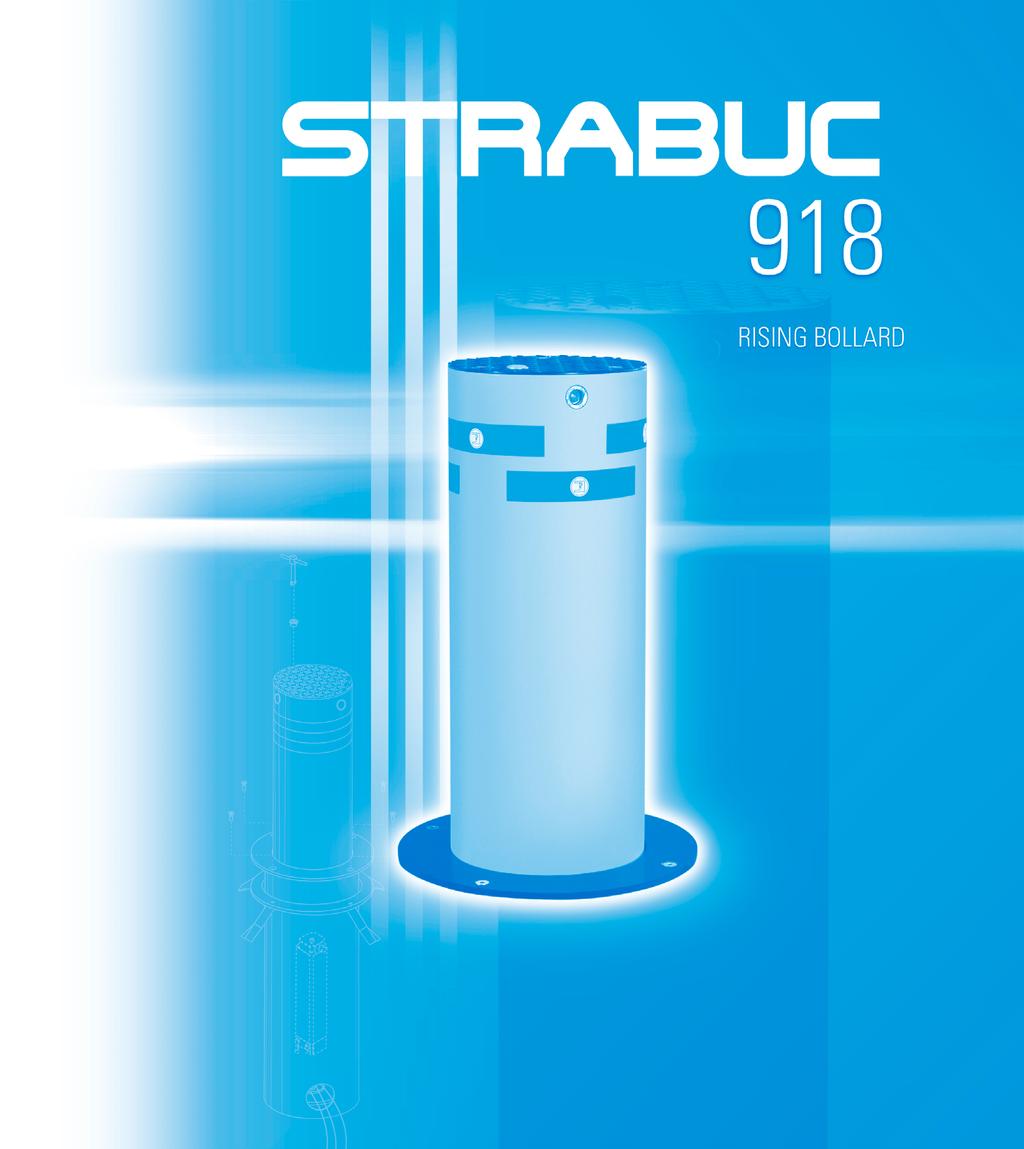
2 RISING BOLLARD OIL-HYDRAULIC AUTOMATION COMPONENTS strabuc 918 RELEASE KEY PLUG FOR RELEASE HOLE BOLLARD COVER 12 V WARNING LIGHTS REFLECTORS COMPLETELY RETRACTABLE POST WITH ELECTROPHORESIS ANTI- CORROSION TREATMENT 4 SCREWS FOR FIXING THE POST TO THE ANCHORAGE FLANGE SUPPORT FLANGE WELDED TO THE CONTAINMENT CYLINDER FIXING FLANGE WITH BRACKETS TO BE SET IN CONCRETE AT 1 cm BELOW THE WITH ELECTROPHORESIS ANTI-CORROSION TREATMENT CONTAINMENT CYLINDER IN ELECTROPHORESIS ANTI-CORROSION TREATED STEEL INTERNAL OIL-HYDRAULIC UNIT 3 WATER DRAINAGE AND WIRING HOLES ELECTRIC CABLES WITH EARTH CONNECTION 24 V LIMIT SWITCH CABLE ELECTRIC MOTOR CABLE V TRANSFORMER CABLE FOR WARNING LIGHTS
3 AUTOMATION INSTALLATION INSTRUCTIONS FOR THE STRABUC 918 TO BE INSTALLED AND OPERATE CORRECTLY, WE RECOMMEND TO FOLLOW THE INSTRUCTIONS AND RELATIVE ILLUSTRATIONS BELOW. The Strabuc 918 is an oil-hydraulic traffic bollard which retracts completely down to the level of the road surface. It is designed to prevent vehicles from passing, but can also be completely retracted without leaving the slightest trace. It is an oil-hydraulic automation with an incorporated internal hydraulic unit, while its control programmer, Elpro 10 CEI is installed externally, in a sheltered area. In order to install the Strabuc 918, it is necessary to dig a containment hole and lay an underground conduit for the electric cables. INSTALLATION OF THE FIXING FLANGE AND THE CONCRETE CONTAINMENT SLEEVE - Dig a hole so as to insert a concrete tube beneath the road following the measurements shown in Pic. 1 (make sure that the hole does not cut into the water table or damage other pipes). You should also dig a lateral hole for the insertion of a conduit for the electric cables to be connected to the electronic programmer (to be installed in a dry place). - The concrete sleeve should enable rainwater to drain away through the base, we therefore recommend gravel foundations. - The fixing flange should be cemented into position at 1 cm beneath the road surface (Pic. 2), above the concrete sleeve, so as to allow the Strabuc 918 rising bollard installed inside the concrete sleeve to be on a level with the road surface when re-entering the containment cylinder. FIXING FLANGE WITH BRACKETS CEMENTED 1 cm BENEATH THE 1.10 metres CONCRETE SLEEVE FOR HOUSING THE STRABUC 918 INTERNAL DIAMETER 40 cm ELECTRIC CABLE CONDUIT CONNECTED TO THE CONCRETE SLEEVE FOUNDATION GRAVEL FOR WATER DRAINAGE PIC. 1 WATER DRAINAGE PIPES CROSS-SECTION OF STRABUC 918 INSTALLATION 1 cm FIXING FLANGE WITH CEMENTED BRACKETS STRABUC 918 INSTALLED WITH BOLLARD LOWERED TO LEVEL CONCRETE SLEEVE PIC. 2 CROSS-SECTION OF CONCRETE SLEEVE WITH STRABUC 918 INSTALLED 3
4 PLACING THE STRABUC 918 INTO THE CONCRETE SLEEVE AND PASSING THE ELECTRIC CABLES THROUGH THE CONDUIT Once the fixing flange has been cemented into position, the Strabuc 918 can be placed into the cement sleeve as it is already ready for use. - Open the rising bollard cover by unscrewing the three screws (Pic. 3), thereby uncovering the top of the rising bollard. - Attach a winch to the Strabuc 918 lifting hook and lift the entire bollard, positioning it above the concrete sleeve (Pic. 4) - Place the electrical cables inside the conduit, letting them rest freely on the conduit floor (Pic. 4) - Place the Strabuc 918 inside the concrete sleeve, accompanying the electrical cables at the same time without tugging or cutting them. - Attach the Strabuc 918 to the fixing flange using the four fixture screws - Close the rising bollard cover, screwing the three screws into place. WARNING: After the installation has been completed, there should be at least 30 cm of space between the hole foundation and the bottom of the Strabuc 918 bollard (Pic. 4). 1 REMOVE THE COVER BY UNSCREWING THE 3 SCREWS BOLLARD COVER FIXING SCREWS BOLLARD COVER LIFTING HOOK PIC. 3 FIXING SCREWS 2 USE A WINCH TO INSERT THE AUTOMATION, HOOKING IT TO THE SPECIFIC LIFTING HOOK IMPORTANT: WHILE LIFTING THE BOLLARD, BE CAREFUL NOT TO PULL OR SQUASH THE ELECTRIC CABLES IMPORTANT: 3 INSERT THE ELECTRIC CABLES CONNECTING THE BOLLARD TO THE ELECTRONIC PROGRAMMER INTO THE CONDUIT, LETTING THEM LAY ON THE BASE WITHOUT SHORTENING THEM 4 SCREW THE 4 FIXING SCREWS INTO THE FIXING FLANCE WHICH HAS ALREADY BEEN CEMENTED INTO PLACE AT 1 CM BENEATH THE 5 REPLACE THE COVER AND SCREW THE SCREWS BACK IN CONDUIT FOR ELECTRIC CABLES CONNECTING THE BOLLARD TO THE ELPRO 10 CEI ELECTRONIC PROGRAMMER 30 cm PIC. 4 4 STRABUC 918 INSERTION INTO THE CONCRETE SLEEVE
5 ELECTRICAL CONNECTIONS TO ELPRO 10 CEI PROGRAMMER ALL CONNECTIONS INSIDE THE STRABUC 918 BOLLARD (ELECTRIC MOTOR, LIMIT SWITCH AND WARNING LIGHTS) HAVE ALREADY BEEN MADE. IMPORTANT: all the electrical connections and wiring (Pic. 5) must respect good installation practice and be installed professionally by qualified personnel, in compliance with the current Machinery Directive 98/37/EC safety standards, carrying out a complete risk analysis and adopting suitable safety measures. - The Elpro 10 CEI programmer should be installed in a dry, sheltered place. - The Elpro 10 CEI programmer should be powered by electric wires with a section of 1.5 mm 2, for a maximum distance of 50 metres. For distances of over 50 metres, we recommend using electric wires with a section of 2 mm 2. - Electric wires with a section of 1 mm 2 can be used to power photocells, pushbuttons, keyswitches and accessories. IMPORTANT: before connecting the electricity supply, switch the voltage change switch to 230 V (Pic. 8). 1 2 x 1 mm 2 RGB wire x 1 mm x 1 mm 2 2 x 1 mm x 1 mm x 1 mm 2 8 PIC ELECTRICAL CONNECTIONS DIAGRAM ELECTRIC SYSTEM COMPONENTS: 1 Miri 4 flashing light with incorporated antenna 2 Prit 19 keyswitches 3 Polo 44 photocell transmitter 4 Astro 43 plug-in card 5 Elpro 10 CEI electronic programmer 6 Electric cable shunt box 7 Differential magneto-thermal mains switch 8 Polo 44 photocell receiver 9 Strabuc 918 rising bollard 10 Small Astro 43 remote control 5
6 RELEASE OPERATION FOR MANUALLY LOWERING THE BOLLARD This operation is generally referred to as the Manual Release operation and involves manually lowering the rising bollard by using a specially moulded key if the Strabuc 918 s power supply happens to be cut off. Warning: This operation only enables the bollard to be lowered and cannot be used to make it rise. 1 - Use a hexagonal key to unscrew the protective plug placed in the bollard cover (Pic. 6) 2 - Insert the release key into the lock inside the bollard cover hole 3 - Turn the release key anti-clockwise, thus making the bollard slowly descend to ground level. RELEASE KEY PROTECTIVE PLUG BOLLARD COVER RISING BOLLARD DESCRIPTION OF ELECTRICAL WIRING CONNECTIONS IN THE STRABUC 918 The Strabuc 918 comes supplied with three electric cables, 10 metres long: a 230 V 50 Hz power supply cable, an electrical limit switch cable and an electrical transformer cable for the warning lights. The connections are only made to the Elpro 10 CEI programmer as illustrated in diagrams in Pic. 7 and Pic. 8. PIC. 6 ALL STRABUC 918 CABLES CAN BE IDENTIFIED BY THEIR IDENTIFICATION LABELS. ELECTRIC MOTOR CABLE LIVE BLACK - LIVE BROWN - NEUTRAL BLUE - EARTH - YELLOW/GREEN - 12µF WARNING LIGHTS TRANSFORMER CABLE LIVE 230 V - BROWN - IN THE CASE OF LACKING IMPETUS ADD A 12µF CAPACITATOR NEUTRAL BLUE - EARTH - YELLOW/GREEN - ELECTRIC CABLE CONDUIT TO BE INSTALLED UNDERGROUND (PIC. 4) LIMIT SWITCH CABLE OPEN LIMIT SWITCH - BLACK - NEUTRAL BLUE - IMPORTANT: IF THE RISING BOLLARD DOES NOT RISE ONCE ALL THE CONNECTIONS HAVE BEEN MADE, INVERT THE LIMIT SWITCHES OPEN AND CLOSE CLOSE LIMIT SWITCH - BROWN - PIC. 7 6
7 TERMINALS FOR THE CONNECTION OF THE PUSH BUTTONS PULIN 3 VOLTAGE CHANGE-OVER SWITCH 400 V 230 V 10 CEI ON PIC. 8 DIP-SWITCH B ON - PHOTOCELLS OFF DURING OPENING ON - REMOTE CONTROL DOES NOT INVERT ON - CLOSES AUTOMATICALLY ON - WITHOUT PRE-FLASHING 24 V OUTPUT 1 CHANNEL RADIO CONTROL PLUG-IN CARD SUPPORT ON N.B: for inverse operations, turn the DIP-SWITCH levers to the OFF position. OFF 3 7 FADINI POWERED CARD N.C. CONTACT. PHOTOCELLS ALL OPERATIONS OPEN, CLOSE & REVERSE RADIO CONTACT MICROPROCESSOR COMMON. PUSH BUTTONS & INDICATOR 1 AMP. FUSE: 24 V OUTPUT TERMINALS N.O. CONTACT. OPEN N.O. CONTACT. CLOSE N.C. CONTACT. STOP DESCRIPTION OF INDIVIDUAL GATE ELECTRONIC PROGRAMMER OPERATION FOR SLIDING GATES Make sure that all the electrical connections comply with the diagram enclosed. Once terminals 21, 22 and 23 are supplied with single-phase 230 V 50 Hz power, the red LED No. 1 should light up, indicating that the card is powered. The OPEN and CLOSE operation timer should be greater than the gate stroke. The PAUSE timer should be adjusted to fit requirements. PROGRAMMER OPERATION LOGIC: following impulse, the warning light comes on and the automation comes into operation after three seconds. The warning light continues to flash during the pause; the flashing light functions for a further three seconds when the gate is closed. In order to deactivate the flashing light before opening (pre-flashing), use DIP-SWITCH B position 4. SETTING DIP-SWITCH B SIGNAL LEDs: LED No. 1: lights up when the card is powered. LED No. 2: Photocells normally lit up. Only switches off when an obstacle is placed between the photocells. LED No. 3: Open, lights up when the relative button is pressed. LED No. 4: Close, lights up when the relative button is pressed. LED No. 5: Stop normally lit up. Switches off if the relative button is pressed. LED No. 6: Closure limit switches off when the gate is completely closed. LED No. 7: Open limit switches off when the gate is completely open. LED No. 8: Radio lights up whenever an impulse is received from the remote control or pushbuttons. RADIO CONTACT. N.O. LIMIT SWITCH. CLOSE. N.C. LIMIT SWITCH. COMMON PEDESTRIAN OPENING CARD CONNECTOR LIMIT SWITCH. OPEN. N.C. 24 V - 3 W max. INDICATOR Should more pairs of photocells be required than the recommended quantity, fit an auxiliary transformer outside the control box. 24 Vac OUTPUT Max. permitted load: 2 pairs photocells 1 radio receiver DWELL TIME CONNECTION WARNINGS: 1) The programmer should be installed in a dry, sheltered place. If it is installed outside, it will require a protective box to protect it from the elements. 2) The whole system should be earthed. 3) If the photocells are not used, create a bridge between terminals 1 and 2. 4) In order to install two pairs of photocells the connections should be made in series with the 1 2 contact normally closed; if installed one next to the other they should be crossed in pairs i.e. transmitter next to the receiver of the next pair. 5) If no pushbuttons are used, create a bridge between terminals 3 and 6. 6) Before the programmer, apply a high-sensitivity 0.03 Amp differential magneto-thermal switch. 7) For single-phase motors use cables of at least 1.5 mm 2. 8) The 24 V~ output to terminals is able to power 2 pairs of photocells plus 1 radio receiver. An auxiliary transformer placed outside the programmer should be used in the case of more than two pairs of photocells or more radio receivers. 9) Terminal No. 11 indicator light output is able to cater for max. 24 V 3 W bulb; terminals No flashing light output maximum absolute power 25 W. PP MOTOR RUN TIME OPEN & CLOSE CUT OFF SWITCH BY COVER KNOB COMMON M SINGLE-PHASE ELECTRIC MOTOR M THREE-PHASE ELECTRIC MOTOR 230 V - 25 W max. FLASHING LAMP NEUTRAL OPEN CLOSE PHASE LIVE NEUTRAL SUPPLY VOLTAGE 230 V SINGLE-PHASE SUPPLY VOLTAGE V THREE-PHASE LINE 630 ma FUSE FLASHING LAMP 5 A FUSE HIGH VOLTAGE N. W.: for special applications, ie. to switch on lights - CCTV etc, SOLID STATE RELAYS are recommended to be used only. Standard relays would affect the micro-processor. ON EARTH DIP-SWITCH B ma FUSE LOGIC N.W.: THIS PANEL IS TESTED TO OPERATE GATES ONLY THROUGH FADINI ACCESSORIES. NO GUARANTEE FOR ACCESSORIES OF OTHER MAKE OR SPECIAL APPLICATIONS. ON OFF 1 - ON: PHOTOCELLS OFF DURING OPENING OFF: PHOTOCELLS INVERT MOTION DURING OPENING 2 - ON: REMOTE CONTROL DOES NOT INVERT OFF: REMOTE CONTROL INVERTS 3 - ON: AUTOMATIC CLOSURE OFF: SEMIAUTOMATIC CLOSURE 4 - ON: WITHOUT PRE-FLASHING OFF: WITH PRE-FLASHING 7
8 TECHNICAL DATA HYDRAULIC UNIT Hydraulic pump...p10 Hydraulic pump capacity l/min. Average working pressure...2 MPa (20 bar) Maximum supplied pump pressure...4 MPa (40 bar) Working temperature C +80 C Hydraulic oil type...oil FADINI A15 by AGIP Static weight of the pump assembly...10 Kg Protection standards...ip 54 OIL-HYDRAULIC PISTON Piston stroke time...6 sec. Useful piston stroke mm Rod diameter...16 mm Piston diameter mm Max. traction force during opening Kg Max. thrust during closure Kg STRABUC 918 total weight Kg Full protection standards...ip 557 Flashing light power supply V - 25 W ELECTRIC MOTOR Power yielded KW (0.33 HP) Power supply voltage / Frequency V - 50 Hz Absorbed current A Absorbed power W Capacitor µf Motor rotation speed revs/min. Duty mode...s 3 PERFORMANCE Duty cycle...6 s Opening - 30 s Pause - 6 s Closing Complete cycle time...42 seconds Complete Opening Pause Closing cycles...85/hour Annual cycles (with 8 hours of use per day)...nr INSPECTIONS AND MAINTENANCE In order to ensure optimal system performance over time and so as to comply with current safety standards, it is necessary to follow the correct maintenance and monitoring procedures for the entire automation, electronic devices and wiring: - Oil-hydraulic automation: maintenance inspection around every 6 months - Electronic devices and safety systems: maintenance inspection monthly. Ø25 Ø 425 Ø 425 thickness 10 mm Ø 325 thickness 6 mm Ø100 Ø 275 thickness 4 mm metres Lineagrafica WARNINGS - Perform a Risk Analysis before every installation and resolve risks through the use of safety devices in compliance with EN and EN safety standards - Follow the instructions provided - Check that the information on the electric motor plate conforms to the distribution network - Dispose of all cardboard, nylon, polystyrene and other packaging with specialized waste disposal firms - If removing the actuator, do not cut the electric wires, but disconnect them from the terminal box by loosening the screws inside the shunt box - Disconnect the mains switch before opening the electrical wire shunt box cover - The whole automation should be earthed with the yellow/green wire - CUSTOMER GUARANTEE CERTIFICATE ON CUSTOMER S REQUEST. We recommend reading the warning regulations, suggestions and observations in this booklet very carefully. The CE mark certifies that the operator conforms to the essential requirements of the European Directive art. 10 EEC 73/23, in relation to the manufacturer s declaration for the supplied items, in compliance with the body of the regulations ISO 9000= UNI EN Automation in conformity to EN 12453, EN safety standard. EUROPEAN MARK CERTIFYING CONFORMITY TO THE ESSENTIAL REQUIREMENTS OF THE STANDARDS 98/37/EC DECLARATION OF CONFORMITY GENERAL WARNINGS EN 12453, EN STANDARDS CEI EN STANDARDS WARRANTY CERTIFICATE ON THE CUSTOMER S REQUEST The growth of MECCANICA FADINI has always been based on the development of guaranteed products thanks to our TOTAL QUALITY CONTROL system which ensures constant quality standards, updated knowledge of the European Standards and compliance with their requirements, in view of an ever increasing process of improvement. Made in Italy s.n.c. Distributor s box AUTOMATIC GATE MANUFACTURERS The manufacturers reserve the right to change the products without any previous notice Via Mantova, 177/A Cerea (Verona) Italy - Tel r.a. - Fax info@fadini.net -
INSPECTIONS AND MAINTENANCE
 GB INSTRUCTIONS MANUAL STRABUC 930 ARMOURED OIL-HYDRAULIC RISING BOLLARD COMPONENTS strabuc 930 RELEASE KEY PROTECTION PLUG TO ACCESS RELEASE HOLE BOLLARD COVER 12V WARNING LIGHTS REFLECTORS RISING POST
BAYT 980. Oil-hydraulic OIL-HYDRAULIC BARRIER FOR TRAFFIC CONTROL INSTALLATION MANUAL. code 4425 Post with fixing base. POLO 44 - optional -
 Oleodinamica BAYT 980 Oil-hydraulic OIL-HYDRAULIC BARRIER FOR TRAFFIC CONTROL POLO 44 - optional - BAYT 980 560 code 4425 Post with fixing base the gate opener Made in Italy INSTALLATION MANUAL GB INSTRUCTIONS
Oil-hydraulic operator for swinging gates
 COMBI 740 Oil-hydraulic operator for swinging gates Below ground Version with two-way locking device Version with brake in open/close cycles Version with 110 and 175 shaft rotation Instruction manual GB
INSTALLATION MANUAL GB
 GB INSTALLATION MANUAL @GB; 66 FITTING INSTRUCTIONS Important: Keep to the instructions outlined in the pages and diagrams that follow to achieve a perfect installation. NUPI 66 is an oil-hydraulic actuator
NYOTA 115. Electro-mechanical sliding gate operator. Instruction manual
 NYOTA 115 Electro-mechanical sliding gate operator Instruction manual GB INSTRUCTIONS FOR THE INSTALLATION OF THE AUTOMATION NYOTA 115 FOR A CORRECT INSTALLATION AND GOOD PERFORMANCE OF NYOTA 115 READ
CHECKING AND MAINTENANCE:
 GB INSTALLATION MANUAL APROLI 480 OIL-HYDRAULIC OPERATOR FOR GARAGE DOORS SECTION VIEW OF THE OIL-HYDRAULIC OPERATOR WITH LAMP AND COVER UPPER SECTION SUPPORT LAMP REFLECTOR LIGHT DIFFUSION COVER 230 V-25
DRIVE 700 OVERALL DIMENSIONS
 GB INSTALLATION MANUAL DRIVE 700 INSTRUCTIONS TO INSTALL THE SYSTEM FOR A PERFECT APPLICATION AND PERFORMANCE OF DRIVE 700 SYSTEM IT IS RECOMMENDED TO KEEP TO THE INSTRUCTIONS AND THE DIAGRAMS IN THIS
Instructions manual. Below ground oil-hydraulic operator for swinging gates. pages 17-32
 Below ground oil-hydraulic operator for swinging gates STANDARD VERSION: 110 or 17 Leaf Rotation Compact, internal drive unit and hydraulic jack Normal version or version with two-way Locking device Models
GB INSTALLATION MANUAL
 GB INSTALLATION MANUAL MEC 800 SPECIAL OIL-HYDRAULIC OPERATOR FOR SWINGING GATES. EXTERNAL APPLICATION. ESSENTIAL COMPONENTS TO FIT THE OPERATOR TO A GATE LEAF FIXING BOLT FLEXIBLE TUBE 0.5 meter STRAIGHT
GB Instructions Manual
 GB Instructions Manual pages - 8 CMYK- 0 0 KYMC- 0 0 KYMC- 0 0 0 KYMC- 8 KYMC- 0 KYMC- 0 0 0 KYMC- 0 0 0 0 Underground oil-hydraulic operator for swinging gates or 7 shaft rotation Compact all-in-one oil-hydraulic
BAYT 980. Oil-hydraulic Road Traffic Barrier. BAYT 980 painted version BAYT 980 stainless steel version inox
 BAYT 980 Oil-hydraulic Road Traffic Barrier BAYT 980 painted version BAYT 980 stainless steel version inox GB Oil-hydraulic road traffic barrier BAYT 980 The Bayt 980 operator is a road barrier used to
INSTALLATION MANUAL (cod )
") is a bollard designed for the management of traffic areas, parkings and protection of public and private accesses. It has an hydraulic system is engineered in our factory to achieve minimum noise and maximum
is a bollard designed for the management of traffic areas, parkings and protection of public and private accesses. It has an hydraulic system is engineered in our factory to achieve minimum noise and maximum
1-24. Oil-hydraulic. Oil-hydraulic road barrier for traffic control from 3 to 8 metres
 GB Instructions manual pages 1-24 Oil-hydraulic Oil-hydraulic road barrier for traffic control from 3 to 8 metres Stainless steel and painted versions Version with aluminium fence Version with articulated
EC MACHINE DIRECTIVE COMPLIANCE DECLARATION
 EC MACHINE DIRECTIVE COMPLIANCE DECLARATION (DIRECTIVE 89/392 EEC, APPENDIX II, PART B) Manufacturer: FAAC S.p.A. Address: Via Benini, 1 40069 - Zola Predosa BOLOGNA - ITALY Hereby declares that: the 770
I - Libretto di istruzioni GB - Instructions manual F - Notices de montage
 I - Libretto di istruzioni GB - Instructions manual F - Notices de montage GB Instructions manual pages 1-20 BOLLARD WITH RETRACTABLE CYLINDRICAL POST OIL-HYDRAULICALLY OPERATED the gate opener made in
D Vers. 03 ELECTROMECHANICAL AUTOMATION FOR SWING GATES
 E5 D811007 15-09-99 Vers. 03 ELECTROMECHANICAL AUTOMATION FOR SWING GATES 122 This product complies with recognised technical standards and safety regulations. We declare that this product is in conformity
EC MACHINE DIRECTIVE COMPLIANCE DECLARATION
 770 EC MACHINE DIRECTIVE COMPLIANCE DECLARATION (DIRECTIVE 89/392 EEC, APPENDIX II, PART B) Manufacturer: FAAC S.p.A. Address: Via Benini, 1 40069 - Zola Predosa BOLOGNA - ITALY Hereby declares that: the
a p prove d ELECTROMECHANICAL SLIDING GATE OPENER
 EN 25 EN 25 ELETROMEHNIL SLIING GTE OPENER G The Junior gear box is built completely of die cast aluminium, and the coupling is supported by shielded roller bearings. ll of the internal operational components
Automatic concealed bollards 275 H600 and 275 H800 with pit
 Automatic concealed bollards 275 H600 and 275 H800 with pit Technical installation manual CE Declaration of conformity Warnings for the installer Bollard technical data Preparing and installing the bollard
FROG KIT. Installation Instructions for a Pair of gates... TECHNICAL HELPLINE THE FROG-P KIT CONSISTS OF:
 CAME UNITED KINGDOM LTD UNIT 3 ORCHARD PARK INDUSTRIAL ESTATE, TOWN STREET, SANDIACRE, NOTTINGHAM NG10 5BP TEL: 0115 921 0430 FAX: 0115 921 0431 TECHNICAL HELPLINE 0115 921 0430 INTERNET - www.cameuk.com
UNDERGROUND OPERATOR FOR SWINGING GATES. WARNING!! Before installing, thoroughly read this manual that is an integral part of the pack
 UNDERGROUND OPERATOR FOR SWINGING GATES COMPAS 2 WARNING!! Before installing, thoroughly read this manual that is an integral part of the pack Our products if installed by qualified personnel capable to
PW320/PW330 USER MANUAL SWING GATE OPENERS 24V DC GEAR MOTOR FOR RESIDENTIAL. Flashing Light. Push Button. Control box. Gate 2.
 PW320/PW330 USER MANUAL SWING GATE OPENERS 24V DC GEAR MOTOR FOR RESIDENTIAL Flashing Light Push Button Control box Gate 2 Gate 1 Declaration of Conformity Applicant: Powertech Electronics Inc. Manufacturer:
AUTOMATION SYSTEM FOR SWING GATES FROG SERIES INSTALLATION MANUAL SUPERFROG
 AUTOMATION SYSTEM FOR SWING GATES FROG SERIES INSTALLATION MANUAL SUPERFROG IMPORTANT SAFETY INSTRUCTIONS FOR INSTALLATION CAUTION: IMPROPER INSTALLATION MAY CAUSE SERIOUS DAMAGE, FOLLOW ALL INSTALLATION
L /2012 rev 0 BISON 45 OTI UNIONE NAZIONALE COSTRUTTORI AUTOMATISMI PER CANCELLI, PORTE SERRANDE ED AFFINI
 L8542965 03/2012 rev 0 BISON 45 OTI UNIONE NAZIONALE COSTRUTTORI AUTOMATISMI PER CANCELLI, PORTE SERRANDE ED AFFINI 1 470 327 F A 500 825 B 243.5 2 C 445 210 15 ±5 205 92 50 2 3 4 I D2 D2 D1 5 T 6 D A
INSTRUCTIONS FOR INSTALLATION
 HYDRAULIC OPERATOR MODO 110-110/L FOR SINGLE- OR DOUBLE-WING SWING GATES INSTRUCTIONS FOR INSTALLATION GENERAL WARNINGS These warnings constitute an integral and essential part of the product and must
SLIDE NEW CONTROL BOARD
 GB SLIDE NEW CONTROL BOARD CN1 CN2 3 4 5 FUSE 2 RL2 RL1 FUSE 1 TR2 TR1 TR3 TR4 U 1 JP1 Ld2 CMR 3 4 CN E Ld7 Ld6 Ld5Ld4Ld3 CN3 3 4 5 6 7 8 9 10 11 SW 12 13 14 Ld1 P2 P1 FUSE 1 FUSE 2 TR1 TR2 TR3 TR4 SW.1
IRREVERSIBLE OPERATOR FOR SWING GATES AND DOORS
 VH IRREVERSIBLE OPERATOR FOR SWING GATES AND DOORS WARNING!! Before installing, thoroughly read this manual that is an integral part of the pack Our products if installed by qualified personnel capable
BISON 20 OM BISON 25 OTI
 L8542939 11/2011 rev 0 BISON 20 OM BISON 25 OTI UNIONE NAZIONALE COSTRUTTORI AUTOMATISMI PER CANCELLI, PORTE SERRANDE ED AFFINI 2 x 1,5 GND 13 8 7 5 RG 58 4 3 4 x 0,35 6 1 2 4 3 x 1,5 min 230V 2 x 0,35
E R A I GATE AUTOMATION DIVISION
 S E R A I GATE AUTOMATION DIVISION INSTALLATION MANUAL MC/5C - 03.5C UNDERGROUND MOTOR 230 Vac FOR WING GATES UP TO 3,00m AND 300 Kg EACH WING + FOUNDATION BOX IN HOT-GALVANISED STEEL Thank you for choosing
PW150/PW200 USER MANUAL SWING GATE OPENERS 24V DC GEAR MOTOR
 PW150/PW200 USER MANUAL SWING GATE OPENERS 24V DC GEAR MOTOR FOR RESIDENTIAL Flashing Light Push Button Control box Declaration of Conformity Applicant: Powertech Electronics Inc. Manufacturer: Timotion
TITANO 400V SLIDING GATE OPENER
 TITANO 400V SLIDING GATE OPENER USE AND MAINTENANCE MANUAL V07 /2018 TECHNICAL FEATURES א א א א QK-T3000 QK-T4000 QK-T6000 (VAC) 400 Three Phase א א א א (W) 700 750 1500 א א א א (A) 1,7 2,2 3,7 א א C -30/+70
L /2012 rev 0 BISON 30 OTI UNIONE NAZIONALE COSTRUTTORI AUTOMATISMI PER CANCELLI, PORTE SERRANDE ED AFFINI
 L8542968 07/2012 rev 0 BISON 30 OTI UNIONE NAZIONALE COSTRUTTORI AUTOMATISMI PER CANCELLI, PORTE SERRANDE ED AFFINI 1 458 250 A F 645 477 B 195 470 270 2 C 13 ±5 156 70 2 3 4 D2 R D2 I D1 T 5 W D H G R
L /2013 rev 0 BISON 35 OTI UNIONE NAZIONALE COSTRUTTORI AUTOMATISMI PER CANCELLI, PORTE SERRANDE ED AFFINI
 L8543019 04/2013 rev 0 BISON 35 OTI UNIONE NAZIONALE COSTRUTTORI AUTOMATISMI PER CANCELLI, PORTE SERRANDE ED AFFINI 1 458 250 A F 645 477 B 195 470 270 2 C 13 ±5 156 70 2 3 4 D2 R D2 I D1 T 5 W D H G R
F ERNI K I T THE FERNI-S KIT CONSISTS OF:
 CAME UNITED KINGDOM LTD ORCHARD PARK INDUSTRIAL ESTATE TOWN STREET, SANDIACRE, NOTTINGHAM, NG10 5BP TEL: 0115 921 0430 FAX: 0115 921 0431 INTERNET - www.cameuk.com E-MAIL - enquiries@cameuk.com TECHNICAL
SWING GATE OPENERS 24V DC GEAR MOTOR
 SWING GATE OPENERS 24V DC GEAR MOTOR FOR RESIDENTIAL USER MANUAL Flashing Light Push Button Control box Gate 2 Gate 1 Index Warnings 2 5. Technical Characteristics 21 1. Product Description and Applications
EC DECLARATION OF CONFORMITY
 EC DECLARATION OF CONFORMITY Manufacturer : Address: Declares that: FAAC S.p.A. Via Benini, 1-40069 Zola Predosa BOLOGNA - ITALY 844 T control board, conforms to the essential safety requirements of the
SWING GATE OPENERS 24V DC GEAR MOTOR
 SWING GATE OPENERS 24V DC GEAR MOTOR FOR RESIDENTIAL USER MANUAL Flashing Light Push Button Control box Gate 2 Gate 1 Index 1. Warnings 2 4. Technical Characteristics 16 2. Product Description 2.1 Applications
Installation manual ASTER AUTOMATION FOR SWING GATES 11_16
 Installation manual ASTER AUTOMATION FOR SWING GATES 11_16 Contents 1. GENERAL SAFETY PRECAUTIONS... page 01 2. INTENDED USE AND APPLICATION... page 01 2.1 Kit contents... page 01 2.2 Technical features...
SUBWING 700 USER S AND INSTALLER S MANUAL V1.0 REV. 04/2017
 SUBWING 700 USER S AND INSTALLER S MANUAL V1.0 REV. 04/2017 00. CONTT 01. SAFETY INSTRUCTIONS INDEX 01. SAFETY INSTRUCTIONS STANDARDS TO FOLLOW 02. OPERATOR CONNECTION SCHEME INSTALLATION MAP TECHNICAL
Automatic concealed bollards 275 H600 and 275 H800 Control station
 Automatic concealed bollards 275 H600 and 275 H800 Control station Technical installation manual CE Declaration Warnings for the installer Bollard electrical connection Technical specifications for control
MEKO OPENER FOR RACK-DRIVEN SLIDING MOTOR
 Installation Manual MEKO OPENER FOR RACK-DRIVEN SLIDING MOTOR 02_2016 1. WARNINGS AND GENERAL SAFETY INSTUCTIONS This manual contains important safety information. An incorrect installation or an improper
INSTALLER AND USER S MANUAL. v4.0 REV. 01/2019
 MBM6 -BARRIER INSTALLER AND USER S MANUAL v4.0 REV. 01/2019 00. CONTT INDEX 01. SAFETY INSTRUCTIONS STANDARDS TO FOLLOW 01. SAFETY INSTRUCTIONS STANDARDS TO FOLLOW 02. PACKAGE INSIDE PACKAGE 03. OPERATOR
SLIDE & OL USER'S AND INSTALLER'S MANUAL V1.0 REV. 06/2017
 SLIDE & OL USER'S AND INSTALLER'S MANUAL V1.0 REV. 06/2017 00. CONTT 01. SAFETY INSTRUCTIONS INDEX 01. SAFETY INSTRUCTIONS STANDARDS TO FOLLOW 02. OPERATOR TECHNICAL SPECIFICATIONS DESCRIPTION DIMSIONS
MOUNTING AND CONNECTING INSTRUCTIONS 1. GATE ARRANGEMENT ENGLISH
 SATURN SATURN is a motor reducer designed for the automation of sliding gates with grease lubrication of the gear in the 600 version; in oil bath in the 1000 and 2000 versions. The irreversibility of the
IMPORTANT NOTICE FOR THE INSTALLER
 EC MACHINE DIRECTIVE COMPLIANCE DECLARATION (DIRECTIVE 89/392 EEC, APPENDIX II, PART B) Manufacturer: FAAC S.p.A. Address: Via Benini, 1 40069 - Zola Predosa BOLOGNA - ITALY Hereby declares that: the 6
DKC400Y AC Sliding Gate Installation Manual. Sliding Gate Opener. Model: DKC400Y. Installation Manual WARNING
 Sliding Gate Opener Model: DKC400Y Installation Manual WARNING Read and thoroughly understand all instructions before installing or operating this automatic gate opener. Failure to do so may cause serious
Installation manual. English. mystrike OPENER FOR RACK-DRIVEN SLIDING MOTOR
 Installation manual English mystrike OPENER FOR RACK-DRIVEN SLIDING MOTOR 1. WARNINGS AND GENERAL SAFETY INSTRUCTIONS This manual contains important safety information. An incorrect installation or an
VER KIT. Installation Instructions TECHNICAL HELPLINE
 CAME UNITED KINGDOM LTD UNIT 3 ORCHARD PARK INDUSTRIAL ESTATE, TOWN STREET, SANDIACRE, NOTTINGHAM NG10 5BP TEL: 0115 921 0430 FAX: 0115 921 0431 TECHNICAL HELPLINE 0115 921 0430 INTERNET - www.cameuk.com
Type of installation. external motor. underground motor. Leaf max length (m) Leaf max length (m) Max leaf weight (kg) V V V
 Leaf max length (m) Max leaf weight (kg) V V V") Type of installation external motor Residential 391 24V 390 230V 390 24V 412 230V 413 230V 415 415 24V S418 402 422 422 PED. S450H Condominium 415 L 415 L 24V 422 422 PED. 400 S450H Industrial 400 Leaf
Type of installation external motor Residential 391 24V 390 230V 390 24V 412 230V 413 230V 415 415 24V S418 402 422 422 PED. S450H Condominium 415 L 415 L 24V 422 422 PED. 400 S450H Industrial 400 Leaf
IN-GROUND OPERATOR FOR SWING GATES FROG SERIES INSTALLATION MANUAL FROG-A 230V
 IN-GROUND OPERATOR FOR SWING GATES FROG SERIES INSTALLATION MANUAL FROG-A 230V IMPORTANT INSTALLATION, SAFETY INSTRUCTIONS CAUTION: IMPROPER INSTALLATION MAY CAUSE SERIOUS DAMAGE, FOLLOW ALL INSTALLATION
ELECTRONIC CONTROL PANEL FOR ONE 230VAC MOTOR TECHNICAL INSTALLATION MANUAL FOR AUTOMATIC GATES
 ELECTRONIC CONTROL PANEL FOR ONE 230VAC MOTOR UNIK1E230 (COMPLETE) UNIK1E230SK (WITHOUT BOX AND TRANSFORMER) BOX IP 54 TECHNICAL INSTALLATION MANUAL FOR AUTOMATIC GATES WARNING! Before installing, thoroughly
Contents. EC DECLARATION OF CONFORMITY FOR MACHINES... p. 10. WARNINGS FOR THE INSTALLER... p. 10
 Contents EC DECLARATION OF CONFORMITY FOR MACHINES... p. 10 WARNINGS FOR THE INSTALLER... p. 10 1. DESCRIPTION AND TECHNICAL SPECIFICATIONS... p. 11 1.1. DIMENSIONS... p. 11 2. ELECTRIC DEVICES (standard
DESIGNED FOR RESIDENTIAL APPLICATION KIT PL600/PL1000 SLIDING GATE OPENERS
 SLIDING GATE OPENER DESIGNED FOR RESIDENTIAL APPLICATION KIT PL600/PL1000 SLIDING GATE OPENERS The strongest solution for sliding gates PL600/PL1000 electro-mechanical sliding gate openers are designed
Typical Installation Schematic
 The 760 Gate Automation System The FAAC 760 automation system consists of a monoblock hydraulic unit and foundation box assembly. The system is designed for underground installation, and will not alter
OMATION FOR SLIDING GATES LINESTAR INSTALLATION MANUAL
 AUTOMA OMATION FOR SLIDING GATES LINESTAR INSTALLATION MANUAL CONTENTS 1.0 Description of the system parts page 3 1.1 Description of the parties of the group gearmotor page 3 2.0 General characteristics
Istruzioni, instructions. Motoriduttore a braccio snodato per cancelli battenti Gear motor with articulated arm for swing gates ALPHEO
 Istruzioni, instructions Motoriduttore a braccio snodato per cancelli battenti Gear motor with articulated arm for swing gates ALPHEO 1 Istruzioni, instructions Attention! This manual is for qualified
EC DECLARATION OF CONFORMITY FOR MACHINES (DIRECTIVE 98/37/EC)
") EC DECLARATION OF CONFORMITY FOR MACHINES (DIRECTIVE 98/37/EC) Manufacturer: Address: Declares that: FAAC S.p.A. Via Benini, 1-40069 Zola Predosa BOLOGNA - ITALY The operator mod. 844 R Reversible is built
EC DECLARATION OF CONFORMITY FOR MACHINES (DIRECTIVE 98/37/EC) Manufacturer: Address: Declares that: FAAC S.p.A. Via Benini, 1-40069 Zola Predosa BOLOGNA - ITALY The operator mod. 844 R Reversible is built
Instruction Manual for the. E-SL 450 Series
 Instruction Manual for the E-SL 450 Series Estate Slide Summary of Functions The Estate Slide is only to be used for vehicular Slide gates in a Class I setting. Class I: A vehicular gate opener (or system)
Corso Principi di Piemonte, 65/ RACCONIGI (CN) ITALY tel fax
 ITALY tel fax") V2 S.p.A. Corso Principi di Piemonte, 65/67 12035 RACCONIGI (CN) ITALY tel. +39 01 72 81 24 11 - fax +39 01 72 84 050 info@v2home.com - www.v2home.com IL n.131 EDIZ. 28/08/2012 Bingo I GB F E P D NL ATTUATORE
V2 S.p.A. Corso Principi di Piemonte, 65/67 12035 RACCONIGI (CN) ITALY tel. +39 01 72 81 24 11 - fax +39 01 72 84 050 info@v2home.com - www.v2home.com IL n.131 EDIZ. 28/08/2012 Bingo I GB F E P D NL ATTUATORE
GROUND GROUND - ( ) Interrati elettromeccanici ISTRUZIONI PER L INSTALLAZIONE. Electromechanical underground INSTRUCTIONS FOR INSTALLATIONS
 Interrati elettromeccanici ISTRUZIONI PER L INSTALLAZIONE. Electromechanical underground INSTRUCTIONS FOR INSTALLATIONS") GROUND GROUND - (610-624) Interrati elettromeccanici ISTRUZIONI PER L INSTALLAZIONE Electromechanical underground INSTRUCTIONS FOR INSTALLATIONS I UK F E D P NL GR 2 GROUND 1a 6 3 4 7 Ø 5 x4 3 9 1 8 1
GROUND GROUND - (610-624) Interrati elettromeccanici ISTRUZIONI PER L INSTALLAZIONE Electromechanical underground INSTRUCTIONS FOR INSTALLATIONS I UK F E D P NL GR 2 GROUND 1a 6 3 4 7 Ø 5 x4 3 9 1 8 1
ELSEMA 240VAC Slider Control Board, SLD
 SLD Slider Control Board ELSEMA Features For Single 240VAC Motor Built-in transformer, auto close, open only, security close & special security close Application Control an automatic door or gate with
EC DECLARATION OF CONFORMITY FOR MACHINES (DIRECTIVE 98/37/EC) WARNINGS FOR THE INSTALLER
 WARNINGS FOR THE INSTALLER") EC DECLARATION OF CONFORMITY FOR MACHINES (DIRECTIVE 98/37/EC) Manufacturer: Address: Declares that: FAAC S.p.A. Via Benini, 1-40069 Zola Predosa BOLOGNA - ITALY 740-24V mod. operator is built to be integrated
EC DECLARATION OF CONFORMITY FOR MACHINES (DIRECTIVE 98/37/EC) Manufacturer: Address: Declares that: FAAC S.p.A. Via Benini, 1-40069 Zola Predosa BOLOGNA - ITALY 740-24V mod. operator is built to be integrated
Automation Swing Gate Opener
 Automation Swing Gate Opener Operating and installation instructions SP EIFFEL 400 V1.0 Rev 08/01 CONTENTS 0) GENERAL SAFETY REGULATIONS...Page 0 1) DESCRIPTION...Page 03 ) TECHNICAL SPECIFICATIONS 3)
Owner s Manual. For SOLAR BOOM GATE. Model: CA-5000 SOLAR
 ECA Electronic Engineering Pty. LTD. Australia Tel: 03-95720 535 Fax: 95 720 536 Owner s Manual For SOLAR BOOM GATE Model: CA-5000 SOLAR ( 2009 / Version 1 ) 1 1 Introduction 1.0 Control PCB Wiring INSTALLATION
Automatic hidden traffic bollards 275 H600 and 275 H800 with pit
 Automatic hidden traffic bollards 275 H600 and 275 H800 with pit - 0 - Technical installation manual CE Declaration of conformity Warnings for the installer Technical specifications of the traffic bollard
SWING GATE OPENER SW300 SERIES
 USER'S MANUAL SWING GATE OPENER SW300 SERIES 2.50m max. 250kg max. 2.50m max. 250kg max. Important Safety Advice: 1. Knowledge of the relevant electro-technical regulations is required. 2. Training in
V200 USER MANUAL SWING GATE OPENER. 100kg 1.5m. 100kg 1.5m
 V200 USER MANUAL SWING GATE OPENER 100kg 1.m 100kg 1.m Content Important Safety Advice... Content of the Kit... Connection Diagram... Installation Guide... Actuator... Control box... AC cable wiring...
BULL 424 ESA BULL 624 ESA
 L8542677 01/2012 rev 1 BULL 424 ESA BULL 624 ESA UNIONE NAZIONALE COSTRUTTORI AUTOMATISMI PER CANCELLI, PORTE SERRANDE ED AFFINI 1 140 260 92 83 330 330 210 326 2 X BULL.P3 34 mm = = 3 3 4 P P D 102 mm
Installation Manual. Swing Gate System. Leading the way...
 Installation Manual 402 Swing Gate System Leading the way... Contents EC DECLARATION OF CONFORMITY FOR MACHINES... p. 2 WARNINGS FOR THE INSTALLER... p. 2 1. DESCRIPTION AND TECHNICAL SPECIFICATIONS...
FITTING AND CONNECTION INSTRUCTIONS
 LEPUS is an oil-bathed motor-reducer created for sliding gates automation. The motor-reducer irreversibility allows a perfect and safe gate closing avoiding the setup of an electrolock and in case of power
Single or Double 240VAC motor control for domestic and industrial gates and doors.
 COBO30 Double 240V Motor Drive Controller Features For 240Volt Motors Auto Closing Open Only Security Closing and Extended Lock Pulse (user selectable) Travel Timer Push Button Input Photo Cell Input Option
Automation systems for swing gates hydraulic
 70 Automation systems for swing gates hydraulic A wide range of operators designed to respond to the multiple needs of swing gates. BFT automation systems are suitable for any type of gate - heavy, light,
E R A I INSTALLATION MANUAL. Gate Opener Department MERCURIO 302 F MERCURIO 502 F MERCURIO 802 F MERCURIO 501 F
 S E R A I Gate Opener Department MERCURIO 302 F MERCURIO 502 F MERCURIO 802 F MERCURIO 501 F INSTALLATI MANUAL SR 29.75 F KIT WITH ENCODER FOR SLIDING GATES (UP TO 300 kg -230V~) SR 24.29 F KIT WITH ENCODER
MBM8 / MBM11- Barriers. Installer and User s manual
 MBM8 / MBM11- Barriers Installer and User s manual v2.0 REV. 01/2014 00. CONTENT 01.SAFETY INSTRUCTIONS INDEX 00. CONTENT index page 01.A 01. SAFETY INSTRUCTIONS standards to follow page 01.B 02. PACKAGE
contents Installation Maintenance DOOR OPERATOR SLIDING-1300/2100 Installation and Operating Manual DoorHan, 2012
 DOOR OPERATOR contents general information SAFETY INSTRUCTIONS operator unit Installation Electrical Connections Programming of Remote Controls Release Operation Maintenance Troubleshooting Warranty Card
FORCE SPD 800/1500/2000
 English AUTOMATION SYSTEMS FOR SLIDING GATES Operating and installation instructions FORCE SPD 800/1500/2000 v1.0 Rev 11/2012 INDEX 1) General Safety Regulations... pág. 01 2) Description... pág. 02 3)
FEATURES AND SPECIFICATIONS
 FEATURES AND SPECIFICATIONS The is a high quality hydraulic operator for residential and condominium use with leaf length up to 3 m. Available in the following versions: AC (with lock in opening and closing)
CE DECLARATION OF MACHINE CONFORMITY
 CE DECLARATION OF MACHINE CONFORMITY (DIRECTIVE 2006/42/EC) Manufacturer : Address: Declares that: FAAC S.p.A. Via Calari, 10-40069 Zola Predosa BOLOGNA - ITALY Operator mod. 541 3ph is built to be incorporated
E R A I Gate Automation Division
 S E R A I Gate Automation Division INSTALLATI MANUAL SR 24.39 CTROL UNIT TO COMMAND 1 OR 2 12/24Vdc MOTORS FOR THE AUTOMATI OF SWING GATES Thank you for choosing a SERAI ELETTRICA product, which we are
SPEEDROLLER SERVICE MANUAL CE DECLARATIONS LOG BOOK USER MANUAL. Edition : May 2011
 SERVICE MANUAL CE DECLARATIONS LOG BOOK USER MANUAL SPEEDROLLER Edition : May 2011 1 8 2 3 4 Main components 1 drive 2 wind roller with hood (optional) 3 door panel 4 aluminium hinge profile 5 window section
Table of Contents. General Safety Preparation for Installation Parts List Optional Accessories Part List... 5
 REV 12a Table of Contents General Safety....... 2 Preparation for Installation....... 3 Parts List....... 4 Optional Accessories Part List...... 5 Technical Specifications & Feature...... 5 Installation
CAUTION CM-SE CM-S21 CM-S41
 CAUTION Safety, Technology & Innovation CM Series Operating Instructions for, CM-S21,, CM-S11, CMS31 CM Series Safety System This information is designed to help suitably qualified personnel install and
EL5600 Series Electric Linear Actuators Installation and Maintenance Instructions
 3581050/5 IM-P358-05 CH Issue 5 EL5600 Series Electric Linear Actuators Installation and Maintenance Instructions 1 Safety information 2 General 3 Installation 4 Commissioning 5 Maintenance IM-P358-05
SARGON S - M - L. All rights reserved INSTALLATION MANUAL
 INSTALLATION MANUAL Our compliments for your excellent choice. SARGON LINE S (300mm) M (400mm) and L (600mm) electro-mechanical gear motor has been produced for reliability and high quality. This Manual
access
 184 Table of Contents Access Garage door Motors Dexxo Pro 800 RTS... 188 Dexxo Pro 1000 RTS... 189 Dexxo Optimo RTS... 190 Receiver Axroll NS... 191 Freeroll ESE RTS, RTS receiver for roller garage doors...
UNDERGROUND OPERATOR FOR SWING GATES 119AS45EN. Installation manual FROG-A / FROG-AV / FROG-AE. English
 119AS45EN UNDERGROUND OPERATOR FOR SWING GATES Installation manual FROG-A / FROG-AV / FROG-AE English EN WARNING! important safety instructions: READ CAREFULLY! NECESSARY AND IN A VISIBLE PLACE SPECIAL
Installation Manual 820/860. Sliding Gate System. Leading the way...
 Installation Manual 820/860 Sliding Gate System Leading the way... EC MACHINE DIRECTIVE COMPLIANCE DECLARATION (DIRECTIVE 89/392 EEC, APPENDIX II, PART B) Manufacturer: FAAC S.p.A. Address: Via Benini,
PERSA 400 USER S AND INSTALLER S MANUAL V1.0 REV. 10/2016
 PERSA 400 USER S AND INSTALLER S MANUAL V1.0 REV. 10/2016 00. CONTT 01. SAFETY INSTRUCTIONS INDEX 01. SAFETY INSTRUCTIONS STANDARDS TO FOLLOW 02. PACKAGE INSIDE PACKAGE 03. OPERATOR TECHNICAL SPECIFICATIONS
PY600AC Sliding Gate Opener User Manual
 PY600AC Sliding Gate Opener User Manual 2017 Dear users, Thank you for choosing this product. Please read the manual carefully before assembling and using it. Please do not leave out the manual if you
V. 003 QUESTO LIBRETTO È DESTINATO SOLO ALL'INSTALLATORE.
 V. 003 QUESTO LIBRETTO È DESTINATO SOLO ALL'INSTALLATORE. L'installazione dovrà essere effettuata solamente da personale professionalmente qualificato in conformità a quanto previsto dalla legge n 46 del
VERG 24V BARRIER. English
 VERG 24V BARRIER General features VERG 24V is an electro-mechanical barrier (2, 3, 4, 5 m) recommended for the automation of access points which require a high opening/closing speed (parking lots, motorways,
BULL 5M - BULL 5M.S BULL 8M - BULL 8 M.S BULL 8 OM - BULL 8 OM.S
 L8542676 04/2012 rev. 2 BULL 5M - BULL 5M.S BULL 8M - BULL 8 M.S BULL 8 OM - BULL 8 OM.S UNIONE NAZIONALE COSTRUTTORI AUTOMATISMI PER CANCELLI, PORTE SERRANDE ED AFFINI 1 140 260 100 91 330 330 210 326
OpenAir Electric Damper Actuators GDE/GLB Series Non-spring Return Rotary 24 Vac - Modulating Control 0 to 10 Vdc
 Technical Instructions Document No. 155-187P25 EA GDE/GLB-1 OpenAir Electric Damper Actuators GDE/GLB Series Non-spring Return Rotary 24 Vac - Modulating Control 0 to 10 Vdc Description The OpenAir direct
UNIK2E _ V2 (COMPLETE) UNIK2ESK _ V2 (WITHOUT BOX AND TRANSFORMER)
 UNIK2ESK _ V2 (WITHOUT BOX AND TRANSFORMER)") ELECTRONIC CONTROL UNIT FOR TWO 12VDC MOTOR UNIK2E _ V2 (COMPLETE) UNIK2ESK _ V2 (WITHOUT BOX AND TRANSFORMER) BOX IP 54 TECHNICAL INSTALLATION MANUAL FOR AUTOMATIC GATES WARNING! Before installing, thoroughly
ELECTRONIC CONTROL UNIT FOR TWO 12VDC MOTOR UNIK2E _ V2 (COMPLETE) UNIK2ESK _ V2 (WITHOUT BOX AND TRANSFORMER) BOX IP 54 TECHNICAL INSTALLATION MANUAL FOR AUTOMATIC GATES WARNING! Before installing, thoroughly
BARRY BARRIER GATE AUTOMATION
 BARRY BARRIER GATE AUTOMATION Installation Manual 1. WARNINGS AND GENERAL SAFETY INSTUCTIONS This manual contains important safety information. An incorrect installation or an improper use may cause serious
CONTROL UNIT BIOS2. Manual for installation. Programmable Control board for wings gates.
 Programmable Control board for wings gates www.remotecontrolgates.co.uk Manual for installation Compatible from firmware version BIOS2BT02 CONTROL UNIT BIOS2 1. Introduzione The control unit BIOS2 is particularly
Sliding Gate Operator User's Manual
 Sliding Gate Operator User's Manual PY800AC/PY00AC. Products introduction Please read the instructions carefully before proceeding. MCU is supplied to control the gate operator. Keypad / single button
GL1200T Cut & Seal. (GL1200 Seal only)
") GL INSTRUMENTS & Operating Instructions Safe Seal Cut & Seal Welder for Filter Sacks GL1200T Cut & Seal (GL1200 Seal only) For industrial use only Important Safety & Operating Instructions Please read
GL INSTRUMENTS & Operating Instructions Safe Seal Cut & Seal Welder for Filter Sacks GL1200T Cut & Seal (GL1200 Seal only) For industrial use only Important Safety & Operating Instructions Please read
contents OPERATOR Maintenance SHAFT-120 Installation and Operating Manual DoorHan, 2012
 OPERATOR contents General Information Safety instructions Operator unit operator Installation Electrical Connections adjustment of extreme positions operator programming Release operation Maintenance Trouble
ELECTRIC ACTUATOR MOD. VB015 MAINTENANCE AND INSTALLATION INSTRUCTIONS OF VALBIA ELECTRIC ACTUATORS
 ELECTRIC ACTUATOR MOD. VB015 MAINTENANCE AND INSTALLATION INSTRUCTIONS OF VALBIA ELECTRIC ACTUATORS TABLE OF CONTENTS 1.0 - WARNINGS 2.0 - GENERAL DATA 2.1 - Technical characteristics 2.2 - Data on electrical