DODGE CHALLENGER / CHARGER AND CHRYSLER 300 INTERCOOLED SUPERCHARGER SYSTEM 272A1001 TO SUIT PENTASTAR 3.6L V6
|
|
|
- Roxanne Holland
- 5 years ago
- Views:
Transcription


1 DODGE CHALLENGER / CHARGER AND CHRYSLER 300 INTERCOOLED SUPERCHARGER SYSTEM 272A1001 TO SUIT PENTASTAR 3.6L V6 INSTALLATION INSTRUCTIONS
2 CHANGES TO FACTORY SPECIFICATIONS FUEL: Minimum 95 RON (91 Octane USA) premium unleaded gasoline / fuel to be used at all times. Never allow the engine to knock or detonate as serious engine damage may occur. SERVICING REQUIREMENTS: See maintenance section of this manual. Routinely check the supercharger gearbox oil level on the dipstick provided on the supercharger gearbox, top up level if necessary with Redline 75W90 NS gear or equivalent. Inspect supercharger drive belt at every routine service and replace when required. Drain and replace supercharger oil every 50,000 km or 30,000 miles. Use Redline 75W90 NS gear oil or equivalent. It is critical not to overfill supercharger gearbox as damage will occur. Fill with exactly 60 millilitres or 2.03 US fluid ounces and check the oil level with the dipstick provided. NOTE: Many of the photos shown in this document are of a typical Dodge Challenger vehicle and are similar to a typical Dodge Charger and Chrysler 300 vehicles. Some of the terminology and language used in this instruction may vary from that of the end user / installer s expectations, as some tools and automotive components have different common names in different geographical locations. TOOLS AND CONSUMABLES REQUIRED TO COMPLETE INSTALLATION Metric & inch spanners (wrenches) and sockets Pliers & side cutters (dykes) Metric Allen keys Torque Wrench ½ Breaker bar ½ Drive short extension Flat blade & Philips screwdrivers Hose clamp pliers Torque wrench Trim clip removal tool Electrical tape 3/8 Metric socket set Rubber grease or white petroleum jelly Masking tape Optional: Cooling system refiller.


3 Lower Supercharger Manifold PARTS SUPPLIED Upper Supercharger Manifold with Pulley Idler Bracket, Pulleys and Fasteners Intercooler feed hose 272P7401 Intercooler return hose 272P7403 Pump feed hose 272P7405 Engine breather hose A 263P7419 IAT sensor loom extension Brake booster hose 272P2303 Idler pulley spacer, idler pulley, M8 x 80 hex head screw & washer Pulley Bracket, Pulley, Screws and washers Coolant Crossover


")

")
4 Water pump W/Pump Wiring Harness Intercooler Radiator Radiator mount brackets (X2) with mounting hardware. 6PK2635 (K061037) drive belt Fuel Injectors (X6) M6 Manifold Studs (x7) M6 Nyloc Nuts (x7) 26mm springband clamps (x6) 19mm springband clamp (x2) 6PK Idler pulley (x1) Diablo SP1000 flash tuner
 MAP sensor")
 M6 x 100 (x1) Hex head screws")

 M6 x 20")
5 M6 x 30 Flange head screw (x10) M6 x 25 Flange head screw BLK (x4) MAP sensor adaptor loom Throttle body extension loom M6 x 90 (x1) M6 x 100 (x1) Hex head screws + 6mm x 17mm x 3mm Washers (x2) Clean air duct and hose clamps MAP sensor Drive Pulley Self-tapping screw (x1) ¼ BSPP plug M8 x 16 flange head screw (x2) M6 x 20 flange head screw (x2)
 M8 x 110")

 M10 Flat")
")


 M8 X 40")
6 M10 x 110 hex head bolt (X1) M8 x 110 bolt (X1) Pulley retaining washer M8 flat washers (X5) M10 Flat washers (X3) Idler Spacer (x1) Bearing shim (x1) 60mm Idler pulley (X3) 26mm springband clamp (x6) M10 x 70 bolt (X2) M8 X 40 Socket Head Cap Screw (SHCS)
7 PENTASTAR 3.6L V6 SUPERCHARGER SYSTEM SECTION 1 DISASSEMBLY INSTRUCTIONS PREPARATION Ensure that all components required to install the supercharger system are available, refer to the Parts Supplied section provided earlier. Ensure that all required tools are available. Please read the entire installation manual prior to beginning the installation procedure. Ensure the vehicle is located in a secure position with vehicle tyres secured and hand brake applied. To avoid injury, Sprintex recommends the use of a suitable vehicle lift or appropriate safety stands when the vehicle is required to be lifted. Stands should be positioned as per the vehicle manufacturer s owner s handbook. SAFETY WARNING No unauthorised service or alteration may be undertaken to the Sprintex supercharger. Installation should be carried out in a workshop which is a safe and ventilated working environment with equipment and procedures compliant with local authority guidelines and legal requirements. Installers should ensure adequate hearing, eye, and physical protection is used at all times during the installation process. Installers should take reasonable precautions to avoid fatigue and closely follow the installation instructions during every installation. Sprintex recommends installation should not be carried out unsupervised. Sprintex, its directors, employees and agents will not accept liability for damage accident or injury resulting from the installation process. Safety warnings are also provided throughout this document. Allow engine to cool prior to proceeding with disassembly to prevent scalding.

8 NOTES: During disassembly and removal of components, take notes and ensure parts are labelled and stored safely; this will help with the reassembly. Most of the photos shown in this document are of a typical Dodge Challenger and are similar to a typical Dodge Charger and Chrysler 300 vehicles. Connect and disconnect battery cables, jumper cables or battery charger only with the ignition off. Disconnecting the battery may erase fault codes stored in control module memory. Using diagnostic equipment, check for fault codes before disconnecting battery cables. If the malfunction indicator light (MIL) is illuminated. MIL (Malfunction Indicator Lamp) light. The MIL light can be found in one of two locations, dependant on the market the vehicle has been built for. The MIL light may be an illuminated ENGINE symbol within the instrument cluster. Please refer to the owner s handbook to define which off the above applies to the vehicle to be fitted with the Sprintex unit. Always disconnect the negative battery terminal first. This prevents possible shorting and potential battery damage.


9 1. Fuel System Pressure Relief Remove the fuel fill cap. Remove the fuel pump relay from Power Distribution Centre (PDC). For location of the fuel pump fuse, refer to label on the underside of the PDC cover Start and run the engine until it stalls. Attempt restarting the engine until it will no longer run. Turn the ignition key to the OFF position. Be certain that all electrical accessories are turned off. Re-install the fuse. Disconnect and isolate the negative ( - ) battery terminal. Disconnect and isolate the battery positive cable.

 that secure the front fascia assembly to the")

10 2. Front Fascia Removal. Raise and support the vehicle. Remove the left and right front splash shields as necessary Remove the belly pan. Remove the six mounting fasteners that secure the front fascia assembly (9) to the inside of the front fender. Partially lower the vehicle and remove the push-pin retainers (10) that secure the front fascia assembly to the upper radiator support. Carefully pull the left and front side of the fascia out of the fender mounted fascia mounting brackets. Carefully pull the front fascia assembly forward to disengage the push-pin retainer from the slot in each side of the fascia and disconnect the fog lamp wire harness connectors, if equipped.


11

 sensor Loosen")

12 3. Remove the engine cover. Lift the engine cover retaining grommets off the ball studs and remove the engine cover Disconnect the electrical connector from the Inlet Air Temperature (IAT) sensor Loosen the clamp at the throttle body and at the air cleaner housing. Lift the air inlet hose assembly retaining grommet off the ball stud. Remove the air inlet hose assembly.


.")


13 4. Disconnect brake booster hoses. Disengage the brake booster hose retainer from the upper intake manifold. Disconnect the electrical connectors from the Manifold Absolute Pressure (MAP) sensor and the Electronic Throttle Control (ETC). Disengage the ETC harness from the clip on the throttle body and unfasten the wire harness retainer from the upper intake manifold near the MAP sensor and reposition the wire harness. Disconnect the following hoses from the upper intake manifold; Brake booster vacuum hose, EVAP vapour purge line and completely remove the Positive Crankcase Ventilation hose from the vehicle. Disconnect the crankcase ventilation tube from the airbox. Remove the airbox retaining screw and remove the airbox from the vehicle.
, loosen the stud (3) and reposition the upper intake manifold support bracket (2).")
, loosen two stud retainers (3) and reposition the two upper intake manifold support brackets (2).")

 and remove the upper intake manifold (2). Cover the open intake ports to prevent debris from entering the engine.")
14 5. Intake manifold removal. Unfasten the wire harness retainer (4) from the upper intake manifold support bracket (2) stud retainer (3). Remove the two nuts (1), loosen the stud (3) and reposition the upper intake manifold support bracket (2). Remove the heater core return tube upper support bracket retaining nut (2) and reposition tube (1). Remove the two nuts (1), loosen two stud retainers (3) and reposition the two upper intake manifold support brackets (2). NOTE: The upper intake manifold attaching bolts are captured in the upper intake manifold. Once loosened, the bolts will have to be lifted out of the lower intake manifold and held while removing the upper intake manifold. NOTE: Exercise care not to inadvertently loosen the two fuel rail attachment bolts that are in close proximity of the upper intake manifold attaching bolts. Remove the seven manifold attaching bolts (1) and remove the upper intake manifold (2). Cover the open intake ports to prevent debris from entering the engine. Remove the insulator from the left cylinder head cover Re-tighten the stud retainers and refit the heater core return tube. Re-tighten the upper manifold support bracket and reattach the harness to the stud retainer. Remove the IAT sensor from the manifold and set aside for use later on in the install process Cover the inlet ports to prevent any foreign objects entering the engine.


15 6. Drain the vehicles cooling system. WARNING: Do not remove cylinder block drain plugs or loosen radiator draincock with system hot and under pressure. Serious burns from coolant can occur. DO NOT WASTE reusable coolant. If solution is clean, drain coolant into a clean container for reuse. Remove radiator pressure cap. Raise and support the vehicle. Remove the underbody splash shield. Loosen radiator petcock. Drain coolant into a clean container. 7. Replace the injectors. Disconnect the fuel injector electrical connectors by lifting the red locking tab then apply pressure to the black tab when removing the connector. Place a rag under the fuel rail supply line quick connector to catch any residual fuel while disconnecting the fuel supply hose from the fuel rail. Disconnect the fuel supply line quick-connect fitting at the fuel supply line. Note: Fuel may escape under pressure when any fuel hose is disconnected. Take care to avoid contact with the skin or eyes. Ensure that no ignition source is close by to prevent the risk of fire. Remove the four bolts (1) from the fuel rail (2). CAUTION: When removing the fuel rail from the lower intake manifold, one or more fuel injectors may remain in the intake manifold resulting in residual fuel spilling out onto the engine from the fuel rail.


16 Remove the remaining fuel injectors (1) from the fuel rail (2). Remove the remaining fuel injectors (1) from the lower intake manifold. Lubricate the o-rings of the injectors supplied with the system with rubber grease or white petroleum jelly prior to replacing the OEM injectors. Take care when installing the injectors into the fuel rail to prevent damage to the o-ring. Re-attach the fuel rail with the OEM fasteners and tighten to 7Nm. Re-connect and lock the fuel injector electrical connectors. Lubricate the fuel rail spigot with rubber grease or white petroleum jelly before reconnecting the fuel rail supply line quick connector. Ensure that the connector is locked in place. Remove the grey harness retainers from the valve cover and harness on the left bank, neatly tuck the harness down beside the fuel rail and tie in place with the cable ties supplied. At this stage connect the water pump wiring harness to the injector connector of cylinder #2 and run the wire down beside the radiator. Tie in place with cable ties supplied. Securely attach the harness to the valve cover using the cable ties supplied on both banks. Failure to correctly secure the wiring loom may cause electrical faults in the future with short circuits due to insufficiently secured wiring.


17 8. Remove the OEM coolant cross over. Remove thermostat housing mounting bolts and remove the thermostat housing assembly. Remove the Heater supply hose from the coolant crossover. Remove the coolant crossover mounting bolts. Take notice to the four bolts that bolt directly to the timing cover. Remove the coolant crossover and gaskets. Clean gasket sealing faces Ensure that the gasket is in place prior to installing the supplied cross over. NOTE: The shorter M6 mounting bolts, bolt directly to the engine timing cover. Install the supplied coolant cross over, Hand tighten the M6 mounting screws, then tighten the screws in a criss cross pattern to 12Nm s.
, then slowly rotate the tensioner (7) into the freearm position.")


18 9. Install idler pulleys. Remove main drive belt (4) Rotate belt tensioner (7) until it contacts its stop. Remove belt (4), then slowly rotate the tensioner (7) into the freearm position. Remove the OEM Idler pulley and bolt (1) and replace with supplied pulley spacer, 60mm flat idler pulley, pulley retaining washer and M8 x 80 hex head bolt and tighten to 25Nm. Remove the 2 fasteners from the timing case. Install the supplied drive belt. Attach the pulley bracket to the engine with M8 x 110 hex head bolt and M8 flat washer and M10 x 110 hex head bolt and M10 flat washer tighten M8 fastener to 25Nm, Tighten M10 fasteners to 55Nm, ensure the new belt is fed around the pulley on the pulley bracket prior to tightening fasteners. Attach the heater supply hose to the new coolant crossover and fix in place with the original hose clamps. Attach the thermostat housing, clean the mating areas of timing chain cover and thermostat housing. Ensure the seal is retained in the thermostat housing prior to re-attaching it to the crossover. Position thermostat housing on the coolant cross over and Install two thermostat housing bolts. Tighten bolts to 12 Nm.
19 PENTASTAR 3.6L V6 SUPERCHARGER SYSTEM SECTION 2 INSTALLATION INSTRUCTIONS

.")

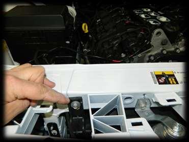
20 10. Install the lower supercharger manifold. Install the 7 manifold studs with a 4mm socket and tighten to 8Nm For stud location see the image below. Note that the right side uses rear position for the stud and the left utilises the front position. Place the four M6 X 25mm black screws into the lower manifold from the underside (see image). Retain screws in place with M6 Nyloc nuts, finger tighten only. Place the lower manifold over the studs & install the M6 Nyloc nuts utilising the four nuts which are retaining the four M6 x 25mm black screws in place. Take care to not drop any nuts down the intake ports. Gently push the lower manifold back towards the bulkhead and tighten the nuts to 12Nm.


21 11. Install the upper supercharger manifold. Carefully lower the upper manifold onto the lower manifold. Place the M6 X 90mm long hex head screw and washer supplied into the upper manifold prior to installation. With the upper manifold in place, start to tighten the two rear screws from the underside, finger tighten only. Place the ten M6 X 30mm flange head screws into the upper manifold, finger tighten the screws to engage the threads. To align the upper manifold to the accessory drive, place the supercharger drive support bracket over the supercharger drive extension and install and tighten the M8 X 40 SHCS on the support bracket, and tighten the screw so the support bracket is firm but still allows the idler bracket to rotate on supercharger drive extension. Next attach the support bracket to the block with the two, M10 x 70 hex head screws and M10 washers, tighten these fasteners up so the support bracket is firmly attached to the timing case but still has some movement from left to right. Tighten the support brackets M8 x 40 SHCS to 10Nm. Place the M6 x 100 hex head screw and washer into bolt hole #4. (see next step for hole identification) Insert the ten M6 X 30 flange head screws into the supercharger manifold then finger tighten all fasteners.


22 12. Tighten the upper manifold Follow the sequence below for tightening the fasteners. Tighten all the fasteners to 8Nm s on first pass. Remove the idler bracket and tighten all fasteners to 12Nm. Attach the throttle body and IAT sensor loom extensions and the MAP sensor adaptor loom extension supplied to the OEM connectors.


23 13. Install the supercharger drive support bracket Re-attach the idler bracket to the timing case, tighten the M10 x 70 hex head screws with the M10 washers to 55Nm then tighten the M8 x 40 SHCS to 15Nm. Attach the bearing shim, to the upper post of the supercharger drive support bracket prior to installing the 6PK grooved idler pulley. Attach the flat idler pulley to the lower post of the support bracket, and tighten both pulleys with two M8 x 16mm screws and two 8.5mm x 25mm x 3mm washers, and tighten to 23Nm. Install a 1mm shim into the back supercharger drive pulley and attach it to the supercharger with the four M6 x 20mm SHCS and tighten to 12Nm. 14. Install the drive belt Install the new drive belt supplied, ensure that the belt is routed correctly (see image below). Relieve the tension on the belt tensioner to complete the fitting of the belt and ensure that the belt is correctly fitted on all pulleys before releasing the belt tensioner


24 15. Install the throttle body Prior to installing the throttle body remove the o- ring seal from the OEM manifold and fit it to the throttle body seal groove of the supercharger manifold. Attach the throttle body to the manifold with the four M6 x 40mm SHCS and washers supplied, and tighten to 12Nm. Connect the throttle body extension loom to the throttle body and secure in place with the OEM harness clip and a cable tie supplied. Trim off excess cable tie. 16. Install the MAP sensor Prior to installing the MAP sensor, lubricate the o-ring with rubber grease or white petroleum jelly attach the MAP sensor to the manifold and secure in place with the self-tapping screw supplied and tighten to 6Nm. Attach the MAP sensor adaptor to the MAP sensor. 17. Install engine breather hose. Attach the straight end of engine breather hose A to the spigot of the rear of the LHS valve cover. Attach the other end of the hose to the manifold, as shown in image below. And attach the EVAP purge hose to the manifold. ENGINE BREATHER HOSE A ¾ I.D. (19MM)


 Insert the check valve into")


25 18. Install the brake booster hose. Disconnect the brake vacuum hose at the T junction, press the white button and remove the fitting. Separate the hose from the T junction. Next separate the check valve from the section of hose removed. Attach the bent section of this hose to the T piece. (see highlighted image) Insert the check valve into the other end of hose, ensuring that the valves orientation is correct. Attach the straight end of the brake booster hose supplied to the check valve, and attach the other end of the brake booster hose to the manifold, secure with spring band clamp supplied. Secure the hose in place with cable ties supplied.


26 19. Install the clean air duct. Install the IAT sensor that was previously removed from the intake manifold, into the new clean air duct supplied. Prior to installing the sensor apply rubber grease to the sensor o-ring to prevent it getting damaged upon installation. Re-install the airbox and secure with the OEM fastener. Loosely attach the hose clamps supplied to the duct and attach the duct to the Airbox and throttle body, tighten the hose clamps to fix the duct in place. Connect the IAT extension loom to the IAT sensor. Re-attach the crankcase ventilation tube to the airbox


27 20. Install the radiator mount brackets and radiator. Prior to installation of the radiator mount brackets remove the air deflectors from the radiator. Install the ¼ BSPP plug supplied, into the radiator and tighten to 16Nm. Pre-assemble the radiator to the brackets, utilising the M6 and M8 X 12 hex head screws, only finger tighten fasteners at this stage. Attach the water pump to LHS radiator mount bracket with the heavy duty cable tie provided. Attach the pump feed hose to the radiator and water pump with the supplied spring band clamps. Remove the screws from the radiator brackets on both sides. Feed the radiator assembly up through the gap between the bumper support frame and air conditioner condenser and attach the radiator assembly to the radiator support panel with the OEM fastener. Ensure the new radiator bracket is place on top of the OEM radiator brackets, finger tighten only. Attach the lower end of the radiator assembly to the radiator support panel with the M6 X 12 hex head screws and M6 Nyloc nuts provided. Note: On the Dodge Charger and Chrysler 300 a Ø6.5mm hole will have to be drilled into the shroud to align the M6 screw to attach to the radiator support panel. Attach the water pump harness to the pump and connect the pump earth connection to the left hand side bottom radiator mount screw. Once all fasteners are installed tighten the M8 fasteners to 16Nm and tighten the M6 fasteners to 12Nm, also tighten the OEM fasteners to 12Nm. Secure the water pump harness to the radiator mount brackets with supplied cable ties.


28
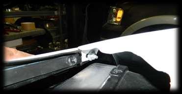
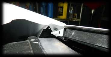
29 21. Install the Intercooler hoses. Feed the intercooler return hose (the black hose in image below) through the gap at the top of the radiator and next to the headlight and attach the hose to the front hose spigot of the supercharger manifold. Attach the other end of the hose to the top spigot of the radiator and fix hose in place with the spring band clamp supplied. Attach the pump feed hose to the lower radiator spigot; attach the other end of the hose to the water pump. Feed the intercooler feed hose (yellow hose in image below) through the gap at the top of the radiator and next to the headlight and attach the hose to the remaining spigot of the supercharger manifold, next attach the other end of the hose to the water pump. Secure the hose with the springband clamp provided. Attach the pump connector to the pump; ensure that the connector is properly secured to the pump. Neatly tie the hoses and wiring harness in place with the cable ties suppled and trim off excess cable ties. Prior to re-installing the air deflectors; on the left hand side of the air deflector a section 50mm tall x 25mm wide, 25mm from the top of the radiator opening will have to be removed to allow the hoses to pass through. Secure hoses in place with the supplied cable ties. Re install the air deflectors.
30 22. Refill the vehicles cooling system Evacuating or purging air from the cooling system involves the use of a pressurized air operated vacuum generator. The vacuum created allows for a quick and complete coolant refilling while removing any airlocks present in the system components. WARNING: ANTIFREEZE IS AN ETHYLENE GLYCOL BASE COOLANT AND IS HARMFUL IF SWALLOWED OR INHALED. IF SWALLOWED, DRINK TWO GLASSES OF WATER AND INDUCE VOMITING. IF INHALED, MOVE TO FRESH AIR AREA. SEEK MEDICAL ATTENTION IMMEDIATELY. DO NOT STORE IN OPEN OR UNMARKED CONTAINERS. WASH SKIN AND CLOTHING THOROUGHLY AFTER COMING IN CONTACT WITH ETHYLENE GLYCOL. KEEP OUT OF REACH OF CHILDREN. DISPOSE OF GLYCOL BASED COOLANT PROPERLY. CONTACT YOUR DEALER OR GOVERNMENT AGENCY FOR LOCATION OF COLLECTION CENTER IN YOUR AREA. DO NOT OPEN A COOLING SYSTEM WHEN THE ENGINE IS AT OPERATING TEMPERATURE OR HOT UNDER PRESSURE; PERSONAL INJURY CAN RESULT. AVOID RADIATOR COOLING FAN WHEN ENGINE COMPARTMENT RELATED SERVICE IS PERFORMED; PERSONAL INJURY CAN RESULT WEAR APPROPRIATE EYE AND HAND PROTECTION WHEN PERFORMING THIS PROCEDURE. NOTE: The service area where this procedure is performed should have a minimum shop air requirement of 80 PSI (5.5 bar) and should be equipped with an air dryer system. NOTE: For best results, the radiator should be empty. The vehicle's heater control should be set to the heat position (ignition may need to be turned to the on position but do not start the motor). Refer to the Chrysler Pentastar Service Equipment (Chrysler PSE) Coolant Refiller # or equivalent tool's operating manual for specific assembly steps. Choose an appropriate adapter cone that will fit the vehicle's radiator filler neck or reservoir tank. Attach the adapter cone (2) to the vacuum gauge Make sure the vacuum generator/venturi ball valve (3) is closed and attach an airline hose (2) (minimum shop air requirement of 80 PSI/5.5 bar) to the vacuum generator/venturi (1). Position the adaptor cone/vacuum gauge assembly into the radiator filler neck or reservoir tank. Ensure that the adapter cone is sealed properly Connect the vacuum generator/venturi (2) to the positioned adaptor cone/vacuum gauge assembly (1) Open the vacuum generator/venturi ball valve. NOTE: Do not bump or move the assembly as it may result in loss of vacuum. Some radiator overflow hoses may need to be clamped off to obtain vacuum. Let the system run until the vacuum gauge shows a good vacuum through the cooling system. Refer to the tool's operating manual for appropriate pressure readings. NOTE: If a strong vacuum is being created in the system, it is normal to see the radiator hoses to collapse. Close the vacuum generator/venturi ball valve. Disconnect the vacuum generator/venturi and airline from the adaptor cone/vacuum gauge assembly. Wait approximately 20 seconds, if the pressure readings do not move, the system has no leaks. If the pressure readings move, a leak could be present in the system and the cooling system should be checked for leaks and the procedure should be repeated. Place the tool's suction hose into the coolant's container. NOTE: Ensure there is a sufficient amount of coolant, mixed to the required strength/protection level available for use. For best results and to assist the refilling procedure, place the coolant container at the same height as the radiator filler neck. Always draw more coolant than required. If the coolant level is too low, it will pull air into the cooling system which could result in airlocks in the system. Connect the tool's suction hose (1) to the adaptor cone/vacuum gauge assembly (2). Open the suction hose's ball valve to begin refilling the cooling system. When the vacuum gauge reads zero, the system is filled.


31 NOTE: On some remote pressurized tanks, it is recommended to stop filling when the proper level is reached. Close the suction hose's ball valve and remove the suction hose from the adaptor cone/vacuum gauge assembly. Remove the adaptor cone/vacuum gauge assembly from the radiator filler neck or reservoir tank. With heater control unit in the HEAT position, operate engine with container cap in place. After engine has reached normal operating temperature, shut engine off and allow it to cool. When engine is cooling down, coolant will be drawn into the radiator from the pressure container. Add coolant to the recovery bottle/container as necessary. Only add coolant to the container when the engine is cold. Coolant level in a warm engine will be higher due to thermal expansion. Add necessary coolant to raise container level to the COLD MINIMUM mark after each cool down period. Once the appropriate coolant level is achieved, attach the radiator cap or reservoir tank cap.


32 23. Secure hoses and wiring Make sure all hoses and wiring are neatly secured with cable ties supplied. 24. Connect battery Connect battery terminals and tighten to 7 Nm. Note: Always connect the positive battery terminal before connecting the negative terminal to reduce the danger of short circuit through the wrench. 25. Fill intercooler system and vehicle cooling system. Remove the intercooler fill cap and fill the system with approximately 1.9 litres of ethylene glycol based automotive engine coolant. Ensure all air is expelled from the system. Air in the intercooler system can reduce engine performance and cause pinging or detonation. 26. Load the ECM re-flash Read the instructions included with the Diablo SP1000 flash tuner. Intune DCX instructions apply. Follow the on screen prompts on the Diablo SP1000 flash tuner.
33 PENTASTAR 3.6L V6 SUPERCHARGER SYSTEM SECTION 3 PRE TEST DRIVE INSPECTION

34 27. Pre start inspection Ensure coolant is at correct level. Ensure engine oil is at correct level. Ensure vehicle has fresh 95 RON (91 Octane USA) premium unleaded fuel or higher. Ensure the belt is correctly installed on each pulley and aligned. Ensure the air filter is clean. Check & replace spark plugs if necessary. Set gap to factory specification. SAFETY WARNING: Ensure adequate steps are taken to prevent injury, spillage or fire should any of the required installation steps not have been carried out to specification. 28. Engine warm up Start engine and allow it to run until engine reaches normal operating temperature. Ensure that the Intercooler water pump is operational. NOTE: If the intercooler water pump is not operating, check pump ground connection to ensure the pump is connected to ground. Check for coolant leaks. Check the intercooler filler cap coolant level with the engine running and top up the system if required. Check engine coolant level and top up if required. NOTE: Do not remove radiator cap for routine coolant level inspections. The coolant level can be checked at coolant recovery bottle (2). The coolant reserve/overflow system provides a quick method for determining coolant level. With engine not running, the coolant level should be between MIN and MAX marks (3). If the coolant level is at or below the MIN mark, fill the recovery bottle with a 50/50 mixture of antifreeze and water ONE QUART AT A TIME. Repeat this procedure until the coolant level is at the FULL mark.


35 29. Check and adjust supercharger pulley alignment. Due to manufacturing tolerances of the original parts, it may be necessary to adjust the alignment of the supercharger pulley to match the other pulleys in the system, either remove or add shims supplied to align the belt. If required, add another shim into the pulley to bring the pulley forward to align the belt as necessary. If the 1mm shim is removed from the pulley to achieve correct belt alignment, the use the shim removed as a washer underneath the pulley bolts when attaching the pulley. Remove the 4, M6 x 20mm SHCS. Relieve the belt tension and remove the belt from the pulley and remove the pulley from the drive extension. Place the shim into the pulley and re-attach the pulley and belt. Tighten the screws to 12Nm. 30. Re-attach the vehicles front fascia. Re-attach the front fascia by reversing the steps in step Road test Road test vehicle. Recheck all joints and connections for leaks and rectify as necessary. Check intercooler system coolant level and top up as necessary. Check engine coolant level and top up as necessary.
36 PENTASTAR 3.6L V6 SUPERCHARGER SYSTEM SECTION 4 MAINTENANCE INSTRUCTIONS
37 32. Supercharger belt replacement It is recommended that the supercharger drive belt be checked at every regular service and be replaced at 50,000 km (30,000 miles) or 2 years, whichever occurs first. 33. Supercharger gear case oil change interval Check oil level every 5,000 to 10,000 km or 3,000 to 6,000 miles, top up oil to correct level if necessary with Redline 75W90 NS gear oil or equivalent. Replace the supercharger oil every 50,000 km or 30,000 miles, use Redline 75W90 NS gear oil or equivalent. It is critical not to overfill the supercharger gear case as damage will occur. Fill with exactly 60 millilitres or 2.03 US fluid ounces. Make sure vehicle is parked on level ground before checking oil level, check the oil level in the supercharger assembly, using the dipstick provided, Tighten the dipstick fully before checking the oil level. Refit the dipstick and tighten to 10Nm. 34. Supercharger gear case oil change procedure Make sure the vehicle is parked on level ground before checking the oil level. Allow sufficient time for the oil level to settle after the engine has been run. Remove the dipstick from the gear case. Using a syringe and a 190mm long piece of tube draw out at much oil as possible from the gear case. Fill the gearbox with Redline 75W90 NS gear oil or equivalent. Check oil level with the dipstick provided in the supercharger. Refit the dipstick and tighten to 10Nm.
JEEP JK INTERCOOLED SUPERCHARGER SYSTEM
 2012 + JEEP JK INTERCOOLED SUPERCHARGER SYSTEM TO SUIT PENTASTAR 3.6L V6 INSTALLATION INSTRUCTIONS 263D1001 CHANGES TO FACTORY SPECIFICATIONS FUEL: Minimum 95 RON (91 Octane USA) premium unleaded gasoline
DODGE RAM 1500 INTERCOOLED SUPERCHARGER SYSTEM
 2013 + DODGE RAM 1500 INTERCOOLED SUPERCHARGER SYSTEM TO SUIT PENTASTAR 3.6L V6 INSTALLATION INSTRUCTIONS 271D1001 CHANGES TO FACTORY SPECIFICATIONS FUEL: Minimum 95 RON (91 Octane USA) premium unleaded
DODGE CHALLENGER / CHARGER AND CHRYSLER 300 INTERCOOLED SUPERCHARGER SYSTEM 272A1001 TO SUIT PENTASTAR 3.6L V6
 2012 2014 DODGE CHALLENGER / CHARGER AND CHRYSLER 300 INTERCOOLED SUPERCHARGER SYSTEM 272A1001 TO SUIT PENTASTAR 3.6L V6 INSTALLATION INSTRUCTIONS Page 1 of 42 TABLE OF CONTENTS INTELLECTUAL PROPERTY USED
JEEP GRAND CHEROKEE INTERCOOLED SUPERCHARGER SYSTEM
 2012 + JEEP GRAND CHEROKEE INTERCOOLED SUPERCHARGER SYSTEM TO SUIT PENTASTAR 3.6L V6 INSTALLATION INSTRUCTIONS 273D1001 Page 1 of 50 TABLE OF CONTENTS INTELLECTUAL PROPERTY USED IN THIS PUBLICATION...4
JEEP JK INTERCOOLED SUPERCHARGER SYSTEM
 2012 + JEEP JK INTERCOOLED SUPERCHARGER SYSTEM TO SUIT PENTASTAR 3.6L V6 263D1001 Page 1 of 49 TABLE OF CONTENTS INTELLECTUAL PROPERTY USED IN THIS PUBLICATION... 4 IMPORTANT INFORMATION / PRODUCT WARNING...
TOYOTA 86 / SUBARU BRZ / SCION FR-S SUPERCHARGER SYSTEM
 SUPERCHARGER SYSTEM INSTALLATION INSTRUCTIONS Page - 1 - of 47 TABLE OF CONTENTS INTELLECTUAL PROPERTY USED IN THIS PUBLICATION...- 4 - IMPORTANT INFORMATION / PRODUCT WARNING...- 5 - CHANGES TO FACTORY
INSTALLATION INSTRUCTIONS
 JEEP- JK (2007-2011) INTERCOOLED SUPERCHARGER SYSTEM 264A1005 / 264A1007 INSTALLATION INSTRUCTIONS System Serial # Supercharger Serial # ECU Serial # Page - 1 - of 60 264D1005 Installation Instructions,
INSTALLATION INSTRUCTIONS
 JEEP- TJ (NON- INTERCOOLED) HARDWARE ONLY (TO SUIT 1997-2004 MODEL VEHICLES) 257A1007 INSTALLATION INSTRUCTIONS Kit Serial # Supercharger Serial # Page - 1 - of 44 257D1007 Installation Instructions, Rev
SPRINTEX MINI Cooper S SUPERCHARGER REPLACEMENT SYSTEM 254A1001 INSTALLATION INSTRUCTIONS
 SPRINTEX MINI Cooper S SUPERCHARGER REPLACEMENT SYSTEM 254A1001 INSTALLATION INSTRUCTIONS IMPORTANT INFORMATION PRODUCT WARNING Installation of the Sprintex Supercharger kit on your Mini Cooper S vehicle
INSTALLATION INSTRUCTIONS
 SPRINTEX Jeep- TJ (Non-Intercooled) (TO SUIT 2005-2006 MODEL VEHICLES) 257D1001 INSTALLATION INSTRUCTIONS Kit Serial # Supercharger Serial # Tuner (ECU reflash unit) Serial # Page - 1 - of 41 257D1001
INSTALLATION INSTRUCTIONS
 JEEP- TJ (NON-INTERCOOLED) (TO SUIT 2005-2006 MODEL VEHICLES) 257A1001 & 257A1005 INSTALLATION INSTRUCTIONS Kit Serial # Supercharger Serial # Tuner (ECU reflash unit) Serial # Page - 1 - of 43 257D1001
SLP Camaro ZL1 STAGE 3 (650 HP)
") SLP - 2012 Camaro ZL1 STAGE 3 (650 HP) PART #26002 PACKING LIST Before installation, use this check list to make sure all necessary parts have been included. ITEM QTY CHECK PART NUMBER DESCRIPTION 1. 1
SLP - 2012 Camaro ZL1 STAGE 3 (650 HP) PART #26002 PACKING LIST Before installation, use this check list to make sure all necessary parts have been included. ITEM QTY CHECK PART NUMBER DESCRIPTION 1. 1
2006 Honda Civic SI Supercharger Kit Installation Instruction Kit #
 2006 Honda Civic SI Supercharger Kit Installation Instruction Kit #350-091 3239 MONIER CIRCLE, STE.5 RANCHO CORDOVA, CA 95742 916.635.4550 FAX 916.635.4632 www.ct-engineering.com INS-157 VERSION: 3.25.2009
Edelbrock E-Force Supercharger Part #1538: Dodge 1500 Truck 5.7L V8 HEMI
 Edelbrock E-Force Supercharger Part #1538: 2009-2014 Dodge 1500 Truck 5.7L V8 HEMI 2009-14 Dodge 5.7L Hemi 1500 Truck INTRODUCTION Thank you for purchasing the Edelbrock Supercharger System for the 2009-15
This information covers the proper procedure for replacing the Volvo D16F engine in a VT or VNL chassis.
 Volvo Trucks North America Greensboro, NC USA Engine, Replacement DService Bulletin Trucks Date Group No. Page 10.2007 210 139 1(47) Engine, Replacement Volvo D16F VNL, VT W2005773 This information covers
INSTALLATION INSTRUCTIONS
 JEEP- JK (2007-2011) SUPERCHARGED INTERCOOLER UPGRADE KIT 264A1001 INSTALLATION INSTRUCTIONS System Serial # Page - 1 - of 39 264D1001 Installation Instructions, Rev 1.06 Table of Contents INTELLECTUAL
2014 RAM C/V Tradesman
 Fig. 91: Suction Hose Ball Valve NOTE: View typical 14. Open the suction hose's ball valve to begin refilling the cooling system. 15. When the vacuum gauge reads zero, the system is filled. NOTE: On some
FREE $15 Gift Card for every $100 spent on Ship To Home orders. Find Out How
 1 of 29 10/12/2011 5:05 PM FREE $15 Gift Card for every $100 spent on Ship To Home orders. Find Out How Ford Ranger/Explorer/Mountaineer 1991-1999 Intake Manifold REMOVAL & INSTALLATION Print The engines
Procharger Stage II Intercooled Supercharger System (11-14 GT)
") Procharger Stage II Intercooled Supercharger System (11-14 GT) Installation Time: Approximately one day. Installed on 2012 Mustang GT 5.0/Manual Required Tools 3/8 Socket Set (Standard and Metric) 1/2
Procharger Stage II Intercooled Supercharger System (11-14 GT) Installation Time: Approximately one day. Installed on 2012 Mustang GT 5.0/Manual Required Tools 3/8 Socket Set (Standard and Metric) 1/2
Edelbrock E-Force Supercharger Dodge/Chrysler 5.7L and 6.4L HEMI Part #1534, 1535, and 15350
 Edelbrock E-Force Supercharger 2011-2013 Dodge/Chrysler 5.7L and 6.4L HEMI Part #1534, 1535, 15340 and 15350 PLEASE COMPLETE THIS PROCEDURE PRIOR to starting the installation of your E-Force supercharger
INSTALLATION INSTRUCTIONS
 INNOVATE MOTORSPORTS SCION FR-S / SUBARU BRZ / TOYOTA FT86 SUPERCHARGER KIT FOR INNOVATE PART NUMBERS 6010 and 6011 INSTALLATION INSTRUCTIONS Kit Serial # Supercharger Serial # 6010 & 6011 Version 1.0
LChevrolet Camaro Supercharger Kit
 PART #92000A Important Notes: 2010-2013 6.2LChevrolet Camaro Supercharger Kit The use of fuel additives (ie. octane boosters) is not recommended. There is a possibility that these chemicals can damage
Always wear safety glasses when working on your vehicle.
 90-93 MAZDA MIATA SUPERCHARGER KIT The KraftWerks 90-93 Mazda Miata Supercharger Kit was designed for easy installation. Competent mechanics with the appropriate tools will find the process to be relatively
16A. STARTING - CHARGING Starter: Removal - Refitting REFITTING 16A-11 K4M II - REMOVAL OPERATION III - FINAL OPERATION
 STARTING - CHARGING Starter: Removal - Refitting 16A K4M II - REMOVAL OPERATION III - FINAL OPERATION JR5 a Clip: -the gearbox control cable sleeve stops on the gearbox, - the control cables onto the gearbox.
APR, LLC
 + 1. 3 3 4. 5 0 2. 5 1 8 1 4 8 0 0 U S H W Y 2 8 0 W e s t, O p e l i k a, A l a b a m a 3 6 8 0 1 4 8 0 0 U S H W Y 2 8 0 W e s t, O p e l i k a, A l a b a m a 3 6 8 0 1 + 1. 3 3 4. 5 0 2. 5 1 8 1 NOTES:
ENGINE COOLING SYSTEM
 B ENGINE A SECTION ENGINE COOLING SYSTEM CO C D CONTENTS E PRECAUTIONS... 2 Precautions for Supplemental Restraint System (SRS) AIR BAG and SEAT BELT PRE-TEN- SIONER... 2 Precautions for Liquid Gasket...
INSTALLATION INSTRUCTIONS
 INSTALLATION INSTRUCTIONS Accessory Application Publications No. AIR CONDITIONER CIVIC 2- AND 4-DOOR AII 24158 Issue Date SEP 2002 What s New The installation instructions for the 2003 Civic A/C are the
2015+ SUBARU STI FRONT-MOUNT INTERCOOLER PARTS LIST AND INSTALLATION GUIDE INSTALL DIFFICULTY DISCLAIMER CAUTION INSTALL PROCEDURE TOOLS NEEDED
 PARTS LIST AND PARTS INCLUDED 1PC ALUMINUM INTAKE PIPE 1PC BAR-AND-PLATE INTERCOOLER 1PC STEEL CRASH BAR W/ MOUNTING HARDWARE 2PC HOT-SIDE INTERCOOLER PIPES 2PC COLD-SIDE INTERCOOLER PIPES 1PC BPV FLANGE
Installation Instructions for: TOYOTA 4.5L SUPERCHARGER SYSTEM
 Installation Instructions for: TOYOTA 4.5L SUPERCHARGER SYSTEM 1995-1997 Land Cruiser * PREMIUM FUEL REQUIRED * Magnuson Products LLC 1990 Knoll Drive, Bldg A, Ventura, CA 93003 (805) 642-8833 phone *
Special Note About The JDM High Performance Water Pump:
 Page 1 of 30 JDM Engineering, Inc. home Call Us! 732-780- 0770 back to Installation Instructions Electric Fan Upgrade Kit Electric Fan Wiring Diagram Thank you for your purchase of the JDM Engineering
 Page 1 of 6 Section 03-01C: Engine, 7.5L MFI 1996 Bronco/F-Series Workshop Manual IN-VEHICLE SERVICE Procedure revision date: 06/19/2000 Cylinder Heads Removal SPECIAL SERVICE TOOL(S) REQUIRED Description
Edelbrock Victor II Intake Manifold. For Chrysler 5.7L (Eagle) and 6.1L Gen III HEMI Engines Part #7179
 and 6.1L Gen III HEMI Engines Part #7179") For Chrysler 5.7L (Eagle) and 6.1L Gen III HEMI Engines PLEASE study these instructions carefully before beginning this installation. You should be familiar with and comfortable working on your vehicle.
For Chrysler 5.7L (Eagle) and 6.1L Gen III HEMI Engines PLEASE study these instructions carefully before beginning this installation. You should be familiar with and comfortable working on your vehicle.
1999 E-Series Workshop Manual
 http://www.fordservicecontent.com/pubs/content/~wsxm/~mus~len/21/sxm31c16.h... Page 1 of 3 SECTION 303-01C: Engine 6.8L 1999 E-Series Workshop Manual IN-VEHICLE REPAIR Procedure revision date: 06/30/1998
INSTALLATION INSTRUCTIONS
 SPRINTEX MINI Cooper S SUPERCHARGER REPLACEMENT SYSTEM 254A1001 INSTALLATION INSTRUCTIONS Kit Serial # Supercharger Serial # ECU Serial # Page - 1 - of 47 Table of Contents INTELLECTUAL PROPERTY USED IN
Light condition and operation Windshield glass condition Wiper blade condition Paint condition and corrosion Fluid leaks Door and hood lock condition
 GENERAL CHECKS Engine Compartment The following should be checked regularly: Engine oil level and condition Transmission fluid level and condition Brake fluid level Clutch fluid level Engine coolant level
Edelbrock Victor II Intake Manifold. For Chrysler 5.7L (Eagle), 6.1L and 6.4L Gen III HEMI Engines Part #7179
, 6.1L and 6.4L Gen III HEMI Engines Part #7179") For Chrysler 5.7L (Eagle), 6.1L and 6.4L Gen III HEMI Engines PLEASE study these instructions carefully before beginning this installation. You should be familiar with and comfortable working on your
For Chrysler 5.7L (Eagle), 6.1L and 6.4L Gen III HEMI Engines PLEASE study these instructions carefully before beginning this installation. You should be familiar with and comfortable working on your
Huron Speed Products Twin Turbo Install Gen 2 CTS-V (09-15)
") Huron Speed Products Twin Turbo Install Gen 2 CTS-V (09-15) 1 2 Remove two bolts in trunk cover with 8mm socket. Pull up on cover to remove. Unscrew net tie down on side cover where battery is located
Huron Speed Products Twin Turbo Install Gen 2 CTS-V (09-15) 1 2 Remove two bolts in trunk cover with 8mm socket. Pull up on cover to remove. Unscrew net tie down on side cover where battery is located
Lower Intake Manifold Replacement
 Lower Intake Manifold Replacement Removal Procedure 1. Turn OFF all the lamps and the accessories. 2. Ensure the ignition switch is in the OFF position. 3. Disconnect the negative battery cable from the
Fuel and exhaust systems 4A 21
 Fuel and exhaust systems 4A 21 15.40 Unscrew the union nuts and disconnect the fuel feed and return hoses from the manifold 41 Disconnect the injector wiring harness connector and the vacuum hose from
Installation Instructions Part Number
 Installation Instructions Part Number 84152143 Thank you for choosing Chevrolet Performance as your high performance source. Chevrolet is committed to providing proven, innovative performance technology
Edelbrock E-Force Supercharger JEEP WRANGLER JK 3.6L V6 Part #1527 and 15270
 Edelbrock E-Force Supercharger 2012-14 JEEP WRANGLER JK 3.6L V6 Part #1527 and 15270 INTRODUCTION Thank you for purchasing the Edelbrock Supercharger System for the Jeep Wrangler with 3.6L V6 Pentastar.
OIL COOLER KIT CHEVY CAMARO 2.0T PARTS LIST AND INSTALLATION GUIDE INSTALL DIFFICULTY DISCLAIMER CAUTION TOOLS NEEDED NOTE INSTALL PROCEDURE
 PARTS LIST AND PARTS INCLUDED 3PC APPLICATION-SPECIFIC MOUNTING BRACKETS 1PC HORN RELOCATION MOUNTING BRACKET 1PC 25-ROW OIL COOLER (SLEEK SILVER OR STEALTH BLACK) 1PC 4'4" STAINLESS STEEL BRAIDED HOSE
1988 Ford F-350 PICKUP
 1988 Ford F-350 PICKUP Submodel: Engine Type: V8 Liters: 7.5 Fuel Delivery: FI Fuel: GAS 1987 93 4.9L Engine The intake and exhaust manifolds on these engines are known as combination manifolds and are
Installation Instructions for: Radix. INTERCOOLED SUPERCHARGER SYSTEM 2008 Hummer H3-Alpha
 Installation Instructions for: Radix INTERCOOLED SUPERCHARGER SYSTEM 2008 Hummer H3-Alpha Step-by-step instructions for installing the best in supercharger systems. ATTENTION! Your MAGNA CHARGER intercooler
ENGINE COOLING SYSTEM
 B ENGINE A SECTION ENGINE COOLING SYSTEM CO C D CONTENTS E PRECAUTIONS... 2 Precautions for Liquid Gasket... 2 REMOVAL OF LIQUID GASKET SEALING... 2 LIQUID GASKET APPLICATION PROCEDURE... 2 PREPARATION...
EXPANSION TANK MUSTANG GT FORD FIESTA ST PARTS LIST AND INSTALLATION GUIDE PARTS LIST AND INSTALLATION GUIDE
 PARTS LIST MMHOSE-MUS8-15L: 4 PC SILICONE HOSES 8 PC CLAMPS 1 PC STAINLESS STEEL ADAPTER MMHOSE-MUS8-15U: 1 PC SILICONE HOSE 1 PC QUICK-DISCONNECT FITTING 1 PC CLAMP MMHOSE-MUS8-15ANC: INSTALLATION INSTRUCTIONS
INTERCOOLED SUPERCHARGER SYSTEM FORD 5.4L 3V F-150 TRUCK
 Installation Instructions for: INTERCOOLED SUPERCHARGER SYSTEM 2004-2006 FORD 5.4L 3V F-150 TRUCK Step-by-step instructions for installing the best in supercharger systems. 89-89-65-001 Rev C Magnuson
GENERAL INSTRUCTIONS
 KYMCO MXU 500i/700i Repair Manual Cooling System 6.Cooling System This chapter covers the location and servicing of the external components for the KYMCO MXU 700i and MXU 500i models. 1.Coolant... 6-4
Installation Manual v1.0: Twin CP3 Fuel Injection Kit Dodge 5.9L
 Installation Manual v1.0: Twin CP3 Fuel Injection Kit 2004.5-2007 Dodge 5.9L Figure 1 - Full Kit Photo 25 Figure 2 - Hardware Kit Please read all instructions before installation. This kit is not emissions
1 of 12 10/5/2015 8:11 AM
 1 of 12 10/5/2015 8:11 AM REMOVAL 1. Perform the fuel pressure release procedure See: Fuel Pressure Release > Procedures > Fuel System Pressure Release Procedure. 2. Recover the refrigerant from the refrigerant
Edelbrock Hemi Supercharger Part #1530, 1531, 1532, 1533, 1536 & 1537
 Edelbrock Hemi Supercharger INTRODUCTION Thank you for purchasing the Edelbrock Hemi Supercharger System for various Chrysler/Dodge vehicles. The Edelbrock E-Force Supercharger System for the 2005 to 2010
Edelbrock E-Force Supercharger JEEP WRANGLER JK 3.6L V6 Part #1527, 1528, and 15270
 Edelbrock E-Force Supercharger 2012-16 JEEP WRANGLER JK 3.6L V6 Part #1527, 1528, 15282 and 15270 WARNING! The supercharger bypass valve is factory installed and adjusted intended to be vacuum operated
COMPONENT LOCATOR > DISASSEMBLED VIEWS
 Page 1 of 45 2006 Pontiac Grand Prix 3.8L Eng Base Service Manual: ENGINE MECHANICAL - 3.8L COMPONENT LOCATOR > DISASSEMBLED VIEWS Fig 1: Engine Block Component Views Callout Component Name 100 Engine
1501 Industrial Way N., Toms River, NJ Fax: PACKING LIST
 1/6/04 1501 Industrial Way N., Toms River, NJ 08755 732-349-2109 Fax:732-244-0867 MODERATE - Installation requires metric tools and possibly cutting and drilling. The ability to closely follow instructions
Installation Instructions for: Toyota 4Runner and FJ Cruiser
 Installation Instructions for: 2010-2017 Toyota 4Runner and 2010-2014 FJ Cruiser Step-by-step instructions for installation of the supercharger system. * PREMIUM GASOLINE FUEL REQUIRED * ATTENTION! Your
Installation Instructions for: Radix. Intercooled Supercharger System GM 4.8L & 5.3L SUV S Only
 Installation Instructions for: Radix Intercooled Supercharger System 07-10 GM 4.8L & 5.3L SUV S Only Step-by-step instructions for installing the best in supercharger systems. * PREMIUM FUEL REQUIRED *
Huron Speed Products Twin Turbo Install Gen 2 CTS-V (09-15)
") Huron Speed Products Twin Turbo Install Gen 2 CTS-V (09-15) The following install guide is simply that, a guide to help you with installation. It is by no means the exact method to perform installation,
Huron Speed Products Twin Turbo Install Gen 2 CTS-V (09-15) The following install guide is simply that, a guide to help you with installation. It is by no means the exact method to perform installation,
SHELBY GT500
 2007-2009 SHELBY GT500 Removal of Factory Unit WARNING: 1. Radiator fluid must be handled properly. Please observe local ordinances with regards to handling and disposal. 2. Allow vehicle and components
SUPERCHARGER. ON-VEHICLE INSPECTION 1. INSPECT SUPERCHARGER OIL LEVEL HINT: With the engine cold, check the oil level on the dipstick.
 EG45 ONVEHICLE INSPECTION 1. INSPECT OIL LEVEL HINT: With the engine cold, check the oil level on the dipstick. (a) Park the vehicle on a level spot and turn the engine off. (b) 4WD: Remove the LH front
2017+ L5P Duramax 3 ½ Down Pipe & EGR Fix Kit
 2017+ L5P Duramax 3 ½ Down Pipe & EGR Fix Kit Covers installation of PN s: WCF100630, WCF100829 Note: This Kit is for off road competition use only! Off Road Competition Use Tuning & Exhaust System is
BBK Intake Manifold Kit ( L) - Installation Instructions
 - Installation Instructions") BBK Intake Manifold Kit (86-93 5.0L) - Installation Instructions The below installation instructions work for the following products: BBK Intake Manifold Kit (86-93 5.0L) Please read through the instructions
BBK Intake Manifold Kit (86-93 5.0L) - Installation Instructions The below installation instructions work for the following products: BBK Intake Manifold Kit (86-93 5.0L) Please read through the instructions
26 - COOLING SYSTEM CONTENTS ENGINE COOLING - DESCRIPTION... 3 ENGINE COOLING - OPERATION... 9 COOLING SYSTEM FAULTS... 1
 26 - COOLING SYSTEM CONTENTS Page LAND ROVER V8 DESCRIPTION AND OPERATION ENGINE COOLING - DESCRIPTION... 3 ENGINE COOLING - OPERATION... 9 FAULT DIAGNOSIS COOLING SYSTEM FAULTS... 1 REPAIR COOLANT - DRAIN
Intake Manifold Removal
 PLEASE READ ALL OF THE FOLLOWING INSTRUCTIONS CAREFULLY PRIOR TO INSTALLATION. AT ANY TIME YOU DO NOT UNDERSTAND THE INSTRUCTIONS Parts included: -GT350 Intake manifold M-944-M5 -GT350 Air bucket w/filter.
This information covers procedures for replacing the sealant for the crankshaft cover on the Volvo D16F engine.
 Volvo Trucks North America Greensboro, NC USA DService Bulletin Trucks Date Group No. Page 1.2008 216 50 1(17) Sealant Crankshaft Cover, Replacement D16F Sealant Crankshaft Cover, Replacement W2005773
ENGINE COOLING GROUP CONTENTS RADIATOR GENERAL DESCRIPTION SPECIAL TOOLS THERMOSTAT
 14-1 GROUP 14 CONTENTS GENERAL DESCRIPTION 14-2 SPECIAL TOOLS 14-3 DIAGNOSIS 14-3 INTRODUCTION 14-3 TROUBLESHOOTING STRATEGY 14-3 SYMPTOM CHART 14-4 SYMPTOM PROCEDURES 14-4 ON-VEHICLE SERVICE 14-17 ENGINE
EXHAUST SYSTEM AND INTAKE MANIFOLD
 J EXHAUST SYSTEM AND INTAKE MANIFOLD 11-1 EXHAUST SYSTEM AND INTAKE MANIFOLD CONTENTS page EXHAUST SYSTEM... 1 EXHAUST SYSTEM DIAGNOSIS... 2 page SERVICE PROCEDURES... 3 TORQUE SPECIFICATIONS... 10 EXHAUST
INSTALLATION INSTRUCTIONS CATCH CAN KIT
 INSTALLATION INSTRUCTIONS CATCH CAN KIT FORD FOCUS Document: 19-0150 Support: info@radiumauto.com STEPS 1 TO 19 COVER THE PCV SIDE CATCH CAN KIT (P/N: 20-0315) STEPS 20-32 COVER THE CRANKCASE CATCH CAN
ADM Performance 6079 Mapleshade Lane Dallas, Texas (214)
") 1) Disconnect Battery Ground 2) Raise front end of Vehicle FAN INSTALL INSTRUCTIONS 3) Remove lower Radiator hose and drain coolant into a pan. (you will reuse coolant later) 4) Remove Air Intake piping
1) Disconnect Battery Ground 2) Raise front end of Vehicle FAN INSTALL INSTRUCTIONS 3) Remove lower Radiator hose and drain coolant into a pan. (you will reuse coolant later) 4) Remove Air Intake piping
HIGH PRESSURE FUEL PUMP 1
 2010 X250, 303-04 FUEL CHARGING AND CONTROLS - V8 5.0L PETROL HIGH PRESSURE FUEL PUMP 1 (G1185928) REMOVAL AND INSTALLATION 19.45.30 HIGH PRESSURE FUEL PUMP FRONT RENEW 5000 CC, AJ V8, NATURALLY ASPIRATED
10-rib belt system upgrade Installation Manual
 10-rib belt system upgrade Installation Manual 2011-2017 and up Ford MUSTANG gt 5.0l coyote WHIPPLE SUPERCHARGERS 3292 NORTH WEBER AVE FRESNO, CA 93722 TEL 559.442.1261 FAX 559.442.4153 A color PDF of
ENGINE ASSEMBLY STOCK TO 250 HP
 GM SPORT COMPACT Performance Build Book 25 ENGINE ASSEMBLY STOCK TO 250 HP Fig. 3 The stock ECOTEC engine has proven reliable to 250 hp.(fig. 3) Performance upgrades are available from GM Performance Parts
L Intake Manifold Part #
 86-93 5.0L Intake Manifold Part #5001-5002 I N S T A L L A T I O N I N S T R U C T I O N S Supplied Materials Bottom cover, Upper manifold, Lower manifold, Plenum cover plate, 1501 Throttle body (comes
INSTALLATION INSTRUCTIONS CATCH CAN KIT
 INSTALLATION INSTRUCTIONS CATCH CAN KIT FORD FOCUS Document: 19-0150 Support: info@radiumauto.com STEPS 1-19 COVER THE PCV SIDE CATCH CAN KIT (P/N: 20-0315) STEPS 20-32 COVER THE CRANKCASE CATCH CAN KIT
4 December 2017 PN# , , Dodge 6.7L Rumble B SXE (I-00400) 1. BD Rumble B SXE. D o d g e 6. 7 L H P C R Installation Instructions
 1. BD Rumble B SXE. D o d g e 6. 7 L H P C R Installation Instructions") 4 December 2017 PN#1045705, 1045706, 1045708 Dodge 6.7L Rumble B SXE (I-00400) 1 DOWNLOAD ENHANCED INSTALL MANUALS AT dieselperformance.com BD Rumble B SXE D o d g e 6. 7 L H P C R Installation Instructions
4 December 2017 PN#1045705, 1045706, 1045708 Dodge 6.7L Rumble B SXE (I-00400) 1 DOWNLOAD ENHANCED INSTALL MANUALS AT dieselperformance.com BD Rumble B SXE D o d g e 6. 7 L H P C R Installation Instructions
Powerstroke EGR Delete A B C
 20-203 6.7 Powerstroke EGR Delete A B C D E F G H I J K Part # A B C D E F G H I J K PACKING LIST: QTY. 3 5 2 Description Sensor Bracket Exhaust Blockoff Plate Straights Barbed Brass Fitting 39 5/8 Coolant
BD TrackMaster S D o d g e H P C R Installation Instructions
 7 July 2016 PN#1045701, 1045702, 1045704 Dodge 6.7L TMS400 (I-00361) 1 BD TrackMaster S400 2008-2012 D o d g e H P C R Installation Instructions 1045701 2008-2009 Dodge 6.7L TMS400 1045702 2010-2012 Dodge
VR6 Supercharger System Golf III and Jetta III VR6 Installation Manual Model Year
 VR6 Supercharger System Golf III and Jetta III VR6 Installation Manual Model Year 1994-1999.5 Date 10/28/00 Page 1 Index 1.0 Parts List 1.1 Required Tools 1.2 Required Standard Parts 1.3 Required Misc.
ENGINE LUBRICATION & COOLING SYSTEMS SECTIONLC CONTENTS. ENGINE LUBRICATION SYSTEM...2 Precautions...2
 ENGINE LUBRICATION & COOLING SYSTEMS SECTIONLC CONTENTS ENGINE LUBRICATION SYSTEM...2 Precautions...2 LIQUID GASKET APPLICATION PROCEDURE...2 Preparation...2 SPECIAL SERVICE TOOLS...2 Lubrication Circuit...3
AIR CLEANER GENERAL REMOVAL. 1CAUTION Do not run engine without filter element in place. Debris could be drawn into the engine causing damage.
 AIR CLEANER GENERAL The air cleaner prevents foreign material from entering the carburetor and engine by trapping airborne dust and dirt in the filter element. Service air cleaner filter element every
Edelbrock 5.0L Mustang GT Supercharger Part #1588 & 1589
 Edelbrock 5.0L Mustang GT Supercharger Part #1588 & 1589 INTRODUCTION Edelbrock 5.0L Ford Supercharger System Thank you for purchasing the Edelbrock 5.0L Ford Supercharger System for the Mustang GT. The
ADJUSTMENTS Mazda MX-3. Fig. 1: Identifying Engine Code & Number Courtesy of MAZDA MOTORS CORP. VALVE CLEARANCE ADJUSTMENT
 Fig. 1: Identifying Engine Code & Number Courtesy of MAZDA MOTORS CORP. ADJUSTMENTS VALVE CLEARANCE ADJUSTMENT 1. No valve clearance adjustment is required, as hydraulic valve lash adjusters are used.
WARNING: ALWAYS relieve fuel pressure before disconnecting any fuel related component. DO NOT allow fuel to contact engine or electrical components.
 4.0L V8 - VINS [K,U] Selected Block 1990 Lexus LS 400 For Lextreme Powertrain 2020 S. Hacienda Blvd. # D Hacienda Heights California 91745 Copyright 1998 Mitchell Repair Information Company, LLC Friday,
M-9424-M50CJ INTAKE MANIFOLD INSTALLATION INSTRUCTIONS
 Please visit www.fordracingparts.com for the most current instruction information!!! PLEASE READ ALL OF THE FOLLOWING INSTRUCTIONS CAREFULLY PRIOR TO INSTALLATION. AT ANY TIME YOU DO NOT UNDERSTAND THE
ENGINE COOLING SYSTEM
 ENGINE SECTION CO A ENGINE COOLING SYSTEM CO C D CONTENTS E PRECAUTION... 2 PRECAUTIONS... 2 Precaution for Supplemental Restraint System (SRS) "AIR BAG" and "SEAT BELT PRE-TEN- SIONER"...2 Precaution
TOYOTA SEQUOIA MY SUPERCHARGER FIT KIT Preparation
 Preparation SEQUOIA FIT KIT: PTR29-0C080 Item Qty Req d Description 1 1 Low Temperature Radiator (LTR) 2 1 TRD Air Filter 3 1 Air Box Lid 4 1 Coolant Cross Over Manifold 5 1 Hardware Bag A 6 1 Hardware
INSTALLATION INSTRUCTIONS COOLANT EXPANSION TANK
 INSTALLATION INSTRUCTIONS COOLANT EXPANSION TANK 2011+ FORD MUSTANG Document: 19-0147 Support: info@radiumauto.com Steps below show installation in a 2015+ Ford Mustang (P/N: 20-0286) The same procedure
TOYOTA FJ CRUISER / 4RUNNER COLD AIR INTAKE Section I Installation Preparation. 4.0L V6 (1GR) Roller Rocker Part Number(s): PTR
 Roller Rocker Part Number(s): PTR") Section I Installation Preparation Part Number(s): PTR03-89100 Kit Contents Item # Quantity Reqd. Description 1 1 Air Filter (P/N: PTR43-00083) 2 1 Upper Air Box 3 1 Lower Air Box 4 1 Hump Coupler 5 1
Section I Installation Preparation Part Number(s): PTR03-89100 Kit Contents Item # Quantity Reqd. Description 1 1 Air Filter (P/N: PTR43-00083) 2 1 Upper Air Box 3 1 Lower Air Box 4 1 Hump Coupler 5 1
Always use fuel with a minimum octane rating of 93 (R+M)/2. (Equivalent to 98 RON).
/2. (Equivalent to 98 RON).") Before Commencing Installation Verify that you have all necessary tools as listed. Clean all air ducting prior to commencing installation. The sequence of installation of each part is very important. It
Before Commencing Installation Verify that you have all necessary tools as listed. Clean all air ducting prior to commencing installation. The sequence of installation of each part is very important. It
2000 Chrysler SEBRING
 2000 Chrysler SEBRING Submodel: JX Engine Type: V6 Liters: 2.5 Fuel Delivery: FI Fuel: GAS 2.0L SOHC and 2.4L DOHC Engines The intake manifold for the 2.0L SOHC engine is a long branch design made of a
BLACKBIRD INSTALLATION SUPPLEMENT
 BLACKBIRD INSTALLATION SUPPLEMENT FOR 2003-7 FORD 6.0 LITER DIESEL SINGLE ALTERNATOR F-350, F-450, F-550, EXCURSION VERSION 7-07 Parts Description Blackbird Wiring Manual Installation Supplement 6.0 Liter
Intake Manifold Replacement
 Page 1 of 14 2004 Chevrolet TrailBlazer - 4WD Bravada, Envoy, Rainier, TrailBlazer (VIN S/T) Service Manual Engine Engine Mechanical - 4.8L, 5.3L, and 6.0L Repair Instructions - On Vehicle Document ID:
1 Engine and peripherals
 1 Engine and peripherals Engine cooling circuit: Specifications -3 Engine cooling circuit: check -5 Engine cooling circuit: Operating diagram -7 Engine cooling: Parts and consumables for the repair work
1997 Volvo 850 GLT. Fig. 2: Removing Drive Shaft, Engine Mount Bolt & Torque Arm (5-Cylinder) Courtesy of VOLVO CARS OF NORTH AMERICA.
 Courtesy of VOLVO CARS OF NORTH AMERICA.") Fig. 2: Removing Drive Shaft, Engine Mount Bolt & Torque Arm (5-Cylinder) 4. Remove front exhaust pipe nuts and springs. Remove front exhaust pipe bolts. Disconnect speedometer. Remove engine mounting
Fig. 2: Removing Drive Shaft, Engine Mount Bolt & Torque Arm (5-Cylinder) 4. Remove front exhaust pipe nuts and springs. Remove front exhaust pipe bolts. Disconnect speedometer. Remove engine mounting
2016+ NISSAN TITAN XD
 PARTS LIST AND PARTS INCLUDED 1PC MISHIMOTO INTERCOOLER 2PC SILICONE BOOTS WITH DURACORE TECHNOLOGY 4PC CONSTANT-TENSION T-BOLT CLAMPS 2PC ALUMINUM SPACERS MOUNTING HARDWARE CAUTION Never work on the cooling
03-04 Mach 1. Hellion Power Systems Mach 1 Kit Instructions
 Hellion Power Systems 03-04 Mach 1 Kit Instructions Part 1 Hellion recommends that the front suspension system be installed either by trained professionals or by 5.Remove rack bolts K-Member Installation
Disconnect the APP sensor harness connector. See Fig. 4. Remove the accelerator pedal mounting nuts. Remove the APP assembly.
 ENGINE CONTROLS - REMOVAL, OVERHAUL & INSTALLATION - 6.6L DIESEL... Page 1 of 41 FUEL SYSTEMS ACCELERATOR PEDAL POSITION SENSOR Removal & Installation Disconnect the APP sensor harness connector. See Fig.
6.7L Cummins EGR Delete
 6.7L Cummins EGR Delete H I A B E C D F J K G L PACKING LIST: Part# A B C D E F G H I J K L QTY. 4 Description Coolant Hose Coolant Hose Connector M0 Flange Nut 5/6 Bolts, Nuts, and Flat Washers /4-0 Bolt,
EXPANSION TANK PARTS LIST AND INSTALLATION GUIDE
 PARTS LIST AND INSTALLATION GUIDE PARTS LIST 1 PC MISHIMOTO RADIATOR 2 PC CAST THERMOSTAT HOUSINGS 1 PC MAGNETIC DRAIN PLUG W/ DOWTY OIL SEAL 4 PC RUBBER BUSHINGS AND METAL COLLARS 3 PC HARDWARE PACKETS
Engine and A4LDE Automatic Transmission Remove and Install ( ) Remove
 Remove") Engine and A4LDE Automatic Transmission Remove and Install ( 3 0) Special Tools 068A -068A Engine lifting bracket -540 Bolt tightening angle gauge Workshop Equipment Transmission jack Workshop crane Assembly
Engine and A4LDE Automatic Transmission Remove and Install ( 3 0) Special Tools 068A -068A Engine lifting bracket -540 Bolt tightening angle gauge Workshop Equipment Transmission jack Workshop crane Assembly
SL63 Weistec M156 Supercharger System Installation Guide Stage 1 / Stage 2
 SL63 Weistec M156 Supercharger System Installation Guide Stage 1 / Stage 2 WARNING! DO NOT HAVE YOUR ECU REPROGRAMMED ANYWHERE BUT AT WEISTEC FOR THIS SUPERCHARGER. THE AMG 63 USES AN ELECTRONIC THROTTLE