HIGH PRESSURE FUEL PUMP 1
|
|
|
- Beatrice Bridget Wade
- 5 years ago
- Views:
Transcription


1 2010 X250, FUEL CHARGING AND CONTROLS - V8 5.0L PETROL HIGH PRESSURE FUEL PUMP 1 (G ) REMOVAL AND INSTALLATION HIGH PRESSURE FUEL PUMP FRONT RENEW 5000 CC, AJ V8, NATURALLY ASPIRATED HIGH PRESSURE FUEL PUMP FRONT RENEW 5000 CC, AJ V8, SUPERCHARGED HIGH PRESSURE FUEL PUMP REAR RENEW 5000 CC, AJ V8, NATURALLY ASPIRATED HIGH PRESSURE FUEL PUMP REAR RENEW 5000 CC, AJ V8, SUPERCHARGED REMOVAL USED WITHINS USED WITHINS USED WITHINS USED WITHINS
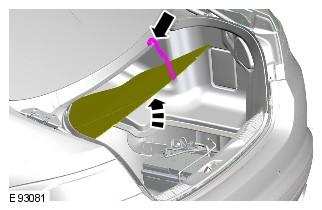
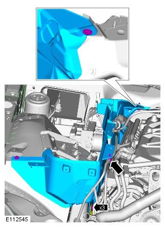
2 WARNING: Do not smoke or carry lighted tobacco or open flame of any type when working on or near any fuel related components. Highly flammable mixtures are always present and may ignite. Failure to follow these instructions may result in personal injury. CAUTION: Make sure that tools and equipment are clean, free of foreign material and lubricant. Some variation in the illustrations may occur, but the essential information is always correct. Refer to: Petrol and Petrol-Ethanol Fuel Systems Health and Safety Precautions ( General Information, Description and Operation). 2. Refer to: Fuel System Pressure Release - V8 5.0L Petrol/V8 S /C 5.0L Petrol ( Fuel System - General Information, General Procedures). 3. Refer to: Secondary Bulkhead Panel LH - TDV6 3.0L Diesel /V8 5.0L Petrol/V8 S/C 5.0L Petrol ( Front End Body Panels, Removal and Installation). 4. Refer to: Secondary Bulkhead Panel RH - TDV6 3.0L Diesel /V8 5.0L Petrol/V8 S/C 5.0L Petrol ( Front End Body Panels, Removal and Installation). 5.
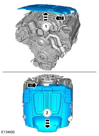
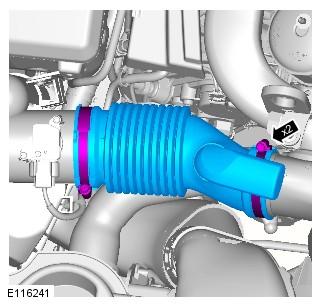
3 Refer to: Engine Cover - V8 5.0L Petrol/V8 S/C 5.0L Petrol ( Interior Trim and Ornamentation, Removal and Installation). 6. Refer to: Fuel Injection Component Cleaning (303-04A Fuel Charging and Controls - V8 5.0L Petrol, General Procedures) Refer to: Air Cleaner Outlet Pipe RH (303-12A Intake Air Distribution and Filtering - V8 5.0L Petrol, Removal and Installation). 10. CAUTIONS:
4 Be prepared to collect escaping fluids. Make sure that all openings are sealed. Use new blanking caps CAUTIONS: Be prepared to collect escaping fuel. Make sure that all openings are sealed. Use new blanking caps.
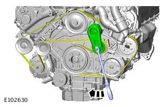
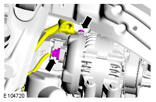
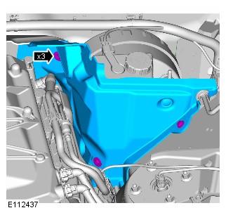
5 13. WARNING: Do not work on or under a vehicle supported only by a jack. Always support the vehicle on safety stands. Raise and support the vehicle. 14. Refer to: Engine Mount RH (303-01A Engine - V8 5.0L Petrol, Removal and Installation). 15. Refer to: Generator - V8 5.0L Petrol ( Generator and Regulator - V8 5.0L Petrol/V8 S/C 5.0L Petrol, Removal and Installation). 16. Engine shown removed for clarity.
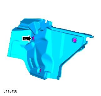
6 17. Engine shown removed for clarity. 18.
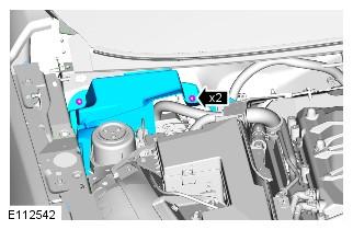
7 Engine shown removed for clarity. 19. CAUTION: Make sure that all openings are sealed. Use new blanking caps.
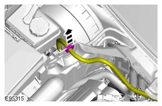
8 20. CAUTIONS: Remove and discard the high-pressure fuel supply lines. Be prepared to collect escaping fluids. Make sure that all openings are sealed. Use new blanking caps. Engine shown removed for clarity. 2
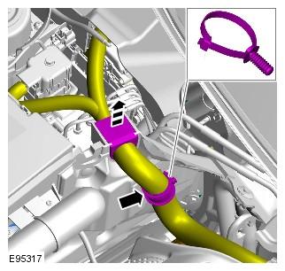
9 22. CAUTION: Be prepared to collect escaping fluids. Loosen the Torx screws a turn each at a time.
10 23. CAUTION: Be prepared to collect escaping fluids. INSTALLATION Lubricate the fuel rail high-pressure fuel pump bucket with clean engine oil.
11 2. CAUTION: Tighten the Torx screws a turn at a time until the correct torque is achieved. Lubricate the fuel rail high-pressure fuel pump O-ring seal with clean engine oil.
12 Install the high-pressure fuel pump. Torque: 12 Nm 3. Loosen the Torx screws half a turn each. 4.
13 5. CAUTIONS: Install new high-pressure fuel supply lines. Lubricate the high-pressure fuel supply line unions with clean engine oil. NOTES: Engine shown removed for clarity. Remove and discard the blanking caps.
14 Install the high-pressure fuel supply lines, tighten the bolts and unions finger tight at stage. 6. CAUTION: Care must be taken when positioning the fuel rail highpressure fuel pump cover to one side.
15 Tighten the Torx screws. Torque: 12 Nm Lower the vehicle. Engine shown removed for clarity.
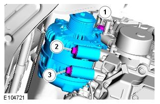
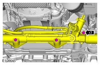
16 Torque: Unions (1) 21 Nm M6 (2) 11 Nm M8 (3) 25 Nm M5 nut (4) 6 Nm 9. Remove and discard the blanking caps.
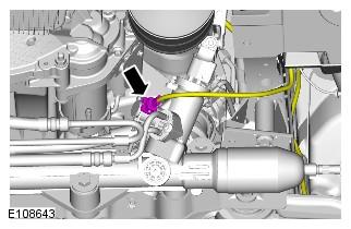
17 Torque: Unions 21 Nm Bolt 12 Nm 10. Install the bolt and unions finger tight before final tightening.
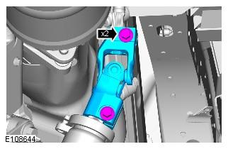
18 Torque: Unions 21 Nm M6 11 Nm 1 Engine shown removed for clarity. Torque: M10 29 Nm M6 11 Nm
19 12. Torque: 25 Nm 13. Refer to: Generator - V8 5.0L Petrol ( Generator and Regulator - V8 5.0L Petrol/V8 S/C 5.0L Petrol, Removal and Installation). 14. Refer to: Engine Mount RH (303-01A Engine - V8 5.0L Petrol, Removal and Installation) NOTES:
20 Do not tighten at this stage. Lubricate the union threads with clean engine oil. Remove and discard the blanking caps. 17. Torque: Unions 21 Nm Bolts 8 Nm 18.
21 Refer to: Air Cleaner Outlet Pipe RH (303-12A Intake Air Distribution and Filtering - V8 5.0L Petrol, Removal and Installation). 2 Refer to: Engine Cover - V8 5.0L Petrol/V8 S/C 5.0L Petrol ( Interior Trim and Ornamentation, Removal and Installation).
22 22. Refer to: Secondary Bulkhead Panel RH - TDV6 3.0L Diesel /V8 5.0L Petrol/V8 S/C 5.0L Petrol ( Front End Body Panels, Removal and Installation). 23. Refer to: Secondary Bulkhead Panel LH - TDV6 3.0L Diesel /V8 5.0L Petrol/V8 S/C 5.0L Petrol ( Front End Body Panels, Removal and Installation). 24. Refer to: Battery Disconnect and Connect ( Battery, Mounting and Cables, General Procedures) X250, BATTERY, MOUNTING AND CABLES BATTERY DISCONNECT AND CONNECT (G ) GENERAL PROCEDURES DISCONNECT If a new battery is installed, the battery monitoring system (BMS) must be reset using Jaguar approved diagnostic equipment.
23 Refer to: Battery and Battery Charging Health and Safety Precautions ( General Information, Description and Operation). 2. Obtain and record the audio unit preset radio frequencies Where fitted. 5. CAUTION: Take extra care not to damage the wiring harness.
24 6. 7. CAUTION: Make sure that the battery negative cable does not move when detaching the negative terminal from the battery.
25 CONNECT CAUTION: Make sure that the battery negative cable to the body retaining bolt is not loose and fully tightened.
26 Torque: 13 Nm 2. Torque: 6 Nm 3.
27 4. Make sure that both the positive and negative battery terminals are correctly located.
28 5. Where fitted. 6. This step is only necessary when installing a new battery. Using Jaguar approved diagnostic equipment, reset the battery monitoring system (BMS). 7. Refer to: Door Window Motor Initialization ( Glass, Frames and Mechanisms, General Procedures). 8. Enter the audio unit preset radio frequencies. 9. Reset the clock to the correct time. 10. Start the engine and allow to idle until the engine reaches normal operating temperature. 1 Switch the engine off.
29 2010 X250, INTERIOR TRIM AND ORNAMENTATION ENGINE COVER - V8 5.0L PETROL/V8 S/C 5.0 L PETROL (G ) REMOVAL AND INSTALLATION ENGINE COVER RENEW 3000 CC, TDV6 0.1 USED WITHINS ENGINE COVER RENEW 5000 CC, AJ V8 0.1 USED WITHINS REMOVAL Removal steps in this procedure may contain installation details. Some variation in the illustrations may occur, but the essential information is always correct.
30 INSTALLATION To install, reverse the removal procedure X250, GENERAL INFORMATION
31 DESCRIPTION AND OPERATION WARNINGS: Fuel may not give adequate warning before toxic or harmful effects arise. Exposure to fuel can be harmful and can cause severe health damage or death. Extreme care must be exercised when handling hot fluids. Always wash off spilled fluids from affected areas of skin immediately. Highly flammable mixtures are always present and may ignite when working on fuel systems. Do not allow naked flames, sparks or lighted substances to come near fuel related components. Fuel must not be used as a cleaning agent. Keep fuel containers tightly closed, out of direct sunlight and in a cool area. Keep away from heat sources, ignition sources and oxidizing agents. SKIN CONTACT: Excessive or prolonged skin contact with diesel fuel may cause serious skin disorders including skin cancer. SKIN CONTACT: Fuel is mildly irritating to the skin and may cause dermatitis due to defatting effect. Remove contaminated clothing. Wash affected areas of skin with soap and water. Seek medical attention for any persistent skin irritation or abnormality. Wash contaminated clothing before reuse. EYE CONTACT: Fuel is mildly irritating to the eyes. Flush with plenty of running water, blinking as often as possible. Do not force the eyelid open. Seek medical attention for any persistent eye irritation or abnormality.
32 SWALLOWED: Fuel is moderately toxic and tends to foam on vomiting. If drawn into the lungs, inflammation may develop. Do not induce vomiting. If spontaneous vomiting occurs place the victim in a forward position to reduce the risk of fuel being drawn into the lungs. Give nothing by mouth. If breathing but unconscious, place in the recovery position. If breathing has stopped, apply artificial respiration. Seek immediate medical attention. INHALED: Fuel is toxic to the respiratory and other body systems. Exposure may result in various symptoms including drowsiness, unconsciousness or severe health damage. Move a victim to fresh air. Keep a victim warm and at rest. If unconscious, place in the recovery position. If not breathing, apply artificial respiration. Give cardiac massage if necessary. Seek immediate medical attention. CAUTIONS: Fuel injection equipment is manufactured to very precise tolerances and fine clearances. It is essential that absolute cleanliness is observed when working with these components. Make sure that the workshop area in which the vehicle is being worked on is as clean and as dust free as possible X250, GENERATOR AND REGULATOR - V8 5.0L PETROL/V8 S/C 5.0L PETROL GENERATOR - V8 5.0L PETROL (G )
33 GENERATOR - V8 5.0L PETROL (G ) REMOVAL AND INSTALLATION GENERATOR - RENEW 3000 CC, AJ-V6 0.6 USED WITHINS GENERATOR - RENEW 3000 CC, TDV6 1 USED WITHINS GENERATOR - RENEW 5000 CC, AJ V8, NATURALLY ASPIRATED GENERATOR - RENEW 5000 CC, AJ V8, SUPERCHARGED USED WITHINS USED WITHINS REMOVAL Removal steps in this procedure may contain installation details. Refer to: Battery Disconnect and Connect ( Battery, Mounting and Cables, General Procedures). 2. WARNING: Make sure to support the vehicle with axle stands. Raise and support the vehicle. 3. Refer to: Air Deflector ( Front End Body Panels, Removal and Installation).
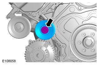
34 4. 5. Torque: 25 Nm 6. Torque: 12 Nm 7. Tighten the bolts in the indicated sequence.
35 Torque: 48 Nm INSTALLATION To install, reverse the removal procedure X250, FUEL CHARGING AND CONTROLS - V8 5.0L PETROL FUEL INJECTION COMPONENT CLEANING GENERAL PROCEDURES FUEL INJECTION COMPONENT CLEANING USING A VACUUM GUN ***DO NOT ISSUE*** GENERAL EQUIPMENT 5000 CC, AJ V8 0 USED WITHINS (G )
36 GENERAL EQUIPMENT EQUIPMENT NAME Pneumatic vacuum gun CLEANING WARNINGS: Do not carry out any repairs to the fuel system with the engine running. Failure to follow this instruction may result in personal injury. Do not smoke or carry lighted tobacco or open flame of any type when working on or near any fuel related components. Highly flammable vapors are always present and may ignite. Failure to follow these instructions may result in personal injury. If fuel contacts the eyes, flush the eyes with cold water or eyewash solution and seek immediate medical attention. Place the vehicle in a well ventilated, quarantined area and arrange ' No Smoking/Petrol Fumes' signs about the vehicle. Wash hands thoroughly after fuel handling, as prolonged contact may cause irritation. Should irritation develop, seek medical attention. Do not carry or operate cellular phones when working on or near any fuel related components. Highly flammable vapors are always present and may ignite. Failure to follow these instructions may result in personal injury. CAUTIONS:
37 Before using the cleaning fluid, protect all electrical components and connectors with lint-free non-flocking material. Make sure that all parts removed from the vehicle are placed on the lint-free non-flocking material. Make sure that any protective clothing worn is clean and made from lint-free non-flocking material. Make sure that clean non-plated tools are used. Clean tools using a new brush that will not lose its bristles, prior to starting work on the vehicle. Use a steel topped workbench and cover it with clean, lint-free non-flocking material. Make sure the workshop area in which the vehicle is being worked on is as clean and as dust free as possible. Foreign matter from work on clutches, brakes or from machining or welding operations can contaminate the fuel system and may result in later malfunction. Using a new brush that will not lose its bristles, brush the components being removed and the surrounding area. 2. Using a pneumatic vacuum gun, remove all traces of foreign material. General Equipment: Pneumatic vacuum gun 2010 X250, ENGINE - V8 5.0L PETROL ENGINE MOUNT RH (G )
38 ENGINE MOUNT RH (G ) REMOVAL AND INSTALLATION ENGINE MOUNTING - RIGHT HAND RENEW 3000 CC, AJ-V6 0.7 USED WITHINS ENGINE MOUNTING - RIGHT HAND RENEW 3000 CC, TDV6 5.1 USED WITHINS ENGINE MOUNTING - RIGHT HAND RENEW 5000 CC, AJ V8 0.8 USED WITHINS REMOVAL Removal steps in this procedure may contain installation details. All vehicles Refer to: Battery Disconnect and Connect ( Battery, Mounting and Cables, General Procedures). 2. WARNING: Do not work on or under a vehicle supported only by a jack. Always support the vehicle on safety stands.
39 Raise and support the vehicle. 3. Refer to: Air Deflector ( Front End Body Panels, Removal and Installation). All vehicles CAUTION: Support the engine on a jack. The angle may need to be adjusted during this procedure. Support the engine with the lifting equipment. Right-hand drive vehicles 2. Note the fitted position.
40 Torque: 35 Nm 3. Torque: 100 Nm All vehicles
41 Torque: 63 Nm 2. Torque: 48 Nm 3. Do not disassemble further if the component is removed for access only.
42 Torque: 48 Nm INSTALLATION To install, reverse the removal procedure X250, INTAKE AIR DISTRIBUTION AND FILTERING - V8 5.0L PETROL AIR CLEANER OUTLET PIPE RH (G ) REMOVAL AND INSTALLATION AIR CLEANER OUTLET PIPE RIGHT HAND RENEW 5000 CC, AJ V8 0.1 USED WITHINS
43 REMOVAL Removal steps in this procedure may contain installation details. INSTALLATION To install, reverse the removal procedure X250, FRONT END BODY PANELS SECONDARY BULKHEAD PANEL LH - TDV6 3.0 L DIESEL /V8 5.0L PETROL/V8 S/C 5.0L PETROL (G )
44 REMOVAL AND INSTALLATION ENGINE COMPARTMENT LEFT HAND COVER RENEW 3000 CC, TDV6 0.7 USED WITHINS ENGINE COMPARTMENT LEFT HAND COVER RENEW 5000 CC, AJ V8 0.7 USED WITHINS REMOVAL Removal steps in this procedure may contain installation details. All vehicles Refer to: Secondary Bulkhead Center Panel ( Front End Body Panels, Removal and Installation). 2.
45 Torque: 25 Nm Right-hand drive vehicles Left-hand drive vehicles Vehicles with 5.0L
46 Torque: 7 Nm All vehicles Torque: 5 Nm 2.
47 Do not disassemble further if the component is removed for access only. INSTALLATION To install, reverse the removal procedure X250, FRONT END BODY PANELS SECONDARY BULKHEAD PANEL RH - TDV6 3.0 L DIESEL /V8 5.0L PETROL/V8 S/C 5.0L PETROL (G )
48 REMOVAL AND INSTALLATION ENGINE COMPARTMENT RIGHT HAND COVER RENEW 3000 CC, AJ-V6 0.9 USED WITHINS ENGINE COMPARTMENT RIGHT HAND COVER RENEW 3000 CC, TDV6 0.9 USED WITHINS ENGINE COMPARTMENT RIGHT HAND COVER RENEW 5000 CC, AJ V8 0.9 USED WITHINS REMOVAL Removal steps in this procedure may contain installation details. All vehicles Refer to: Secondary Bulkhead Center Panel ( Front End Body Panels, Removal and Installation). 2.
49 Torque: 25 Nm Right-hand drive vehicles Some variation in the illustrations may occur, but the essential information is always correct. Left-hand drive vehicles
50 2. Some variation in the illustrations may occur, but the essential information is always correct. Vehicles with 5.0L Refer to: Air Cleaner RH (303-12A Intake Air Distribution and Filtering - V8 5.0L Petrol, Removal and Installation).
51 Vehicles with diesel engine All vehicles 2.
52 INSTALLATION To install, reverse the removal procedure X250, FUEL SYSTEM - GENERAL INFORMATION
53 FUEL SYSTEM PRESSURE RELEASE - V8 5.0L PETROL/V8 S/C 5.0L PETROL (G ) GENERAL PROCEDURES FUEL SYSTEM 3000 CC, AJ-V6 DEPRESSURISE 0.1 USED WITHINS FUEL SYSTEM 5000 CC, AJ V8 DEPRESSURISE 0.1 USED WITHINS DRAINING Remove the fuel pump fuse. 2. Remove the fuel filler cap. 3. CAUTION: When depressurising the fuel system, make sure that there is no throttle input. Failure to follow this instruction may cause damage to the vehicle. Start the engine and allow it to idle until the engine stalls. 4. Crank the engine for approximately five seconds to make sure that the fuel rail pressure is released. FILLING
54 Make sure all repairs have been carried out before proceeding to the following steps. Install the fuel pump fuse. 2. Install the fuel filler cap. 3. Read and clear stored DTC fault codes.
CAUTION: Make sure that tools and equipment are clean, free of foreign material and lubricant.
 Published: 20-Nov-2013 Fuel Charging and Controls - V8 5.0L Petrol - Fuel Rail RH Removal and Installation Special Tool(s) 310-197 Remover, Fuel Injector 310-198 Installer, Teflon Seal 310-199 Re-shape
Fuel Injector ( )
") Published: Mar 29, 2010 Fuel Injector (196010) Special Service Tools Fuel Injector remover 303-1127 Removal WARNING: Do not smoke or carry lighted tobacco or open flame of any type when working on or near
Published: Mar 29, 2010 Fuel Injector (196010) Special Service Tools Fuel Injector remover 303-1127 Removal WARNING: Do not smoke or carry lighted tobacco or open flame of any type when working on or near
 Page 1 of 32 09-Mar-2014 Fuel Charging and Controls - V8 5.0L Petrol - High Pressure Fuel Pump 1 Removal and Installation Removal CAUTION: Always carry out the cleaning process before carrying out any
Fuel Pump Module. Fuel Pump Module. Special Service tools. Remover/Installer, Fuel Pump Module/Fuel Transfer Pump Locking Ring A 1.
 Fuel Pump Module Fuel Pump Module Special Service tools Remover/Installer, Fuel Pump Module/Fuel Transfer Pump Locking Ring 310-072A 1. WARNING: PLACE THE VEHICLE IN A QUARANTINED AREA AND ARRANGE NO SMOKING/PETROL
INTAKE MANIFOLD (G )
") PUBLISHED: 13-FEB-2018 2011.0 RANGE ROVER SPORT (LS), 303-01 ENGINE - V8 N/A 5.0L PETROL INTAKE MANIFOLD (G1245958) REMOVAL AND INSTALLATION 30.15.02 MANIFOLD - INTAKE - LH /FRONT /EACH - RENEW 5000 CC,
PUBLISHED: 13-FEB-2018 2011.0 RANGE ROVER SPORT (LS), 303-01 ENGINE - V8 N/A 5.0L PETROL INTAKE MANIFOLD (G1245958) REMOVAL AND INSTALLATION 30.15.02 MANIFOLD - INTAKE - LH /FRONT /EACH - RENEW 5000 CC,
M-9407-GT05 Mustang GT Dual Fuel Pump Kit INSTRUCTION SHEET
 Please contact the Techline for the most current instruction information (800) FORD788!!! PLEASE READ THE FOLLOWING INSTRUCTIONS CAREFULLY PRIOR TO INSTALLATION!!! OVERVIEW: The following information describes
FUEL TANK DRAINING. Special Tool(s) Special Tool(s)
 Special Tool(s)") FUEL TANK DRAINING Special Tool(s) Zoom Special Tool(s) WARNING: Do not smoke, carry lighted tobacco or open flame of any type when working on or near any fuel-related component. Highly flammable mixtures
FUEL TANK DRAINING Special Tool(s) Zoom Special Tool(s) WARNING: Do not smoke, carry lighted tobacco or open flame of any type when working on or near any fuel-related component. Highly flammable mixtures
M-9424-M50B 2012 Boss 302 Intake Manifold INSTALLATION INSTRUCTIONS
 !!! PLEASE READ ALL OF THE FOLLOWING INSTRUCTIONS CAREFULLY PRIOR TO INSTALLATION. WARNING: CUSTOM CALIBRATION REQUIRED! CALIBRATION NOT INCLUDED! KIT CONTENTS: 1) Intake Manifold Assembly 2) Assembly
SDS. Safety Data Sheet TCP 950E PRODUCT AND COMPANY IDENTIFICATION HAZARDS IDENTIFICATION
 Page 1 of 6 1 PRODUCT AND COMPANY IDENTIFICATION Product Name: Revision Date: Number: CAS Number: Product Code: Synonyms: Company_ Identification Tri-County Petroleum State Route 1036 Defiance, PA 16672
06/03. Fuel Vapor Odor In Interior Convertible Models Only Repair Procedure. Note: Ensure WDS is loaded with software release JTP 759/24 or later.
 SERVICE XK DATE 06/03 TECHNICAL BULLETIN Fuel Vapor Odor In Interior Convertible Models Only Repair Procedure 303-61 MODEL 1999-2003 MY XK Convertible VIN 031303-A35945 Issue: Owners of some 1999-2003
LINCOLN. Continental 1
 3154_U01.qxd 8/1/03 7:28 AM Page 1 Continental 1 BRAKES...1-27 DRIVE TRAIN...1-21 ENGINE REPAIR...1-7 FUEL SYSTEM...1-20 PRECAUTIONS...1-7 SPECIFICATION CHARTS...1-2 STEERING AND SUSPENSION...1-22 A Air
JOHN DEERE WORLDWIDE COMMERCIAL & CONSUMER EQUIPMENT DIVISION. Lawn Tractors L100, L110, L120, and L130 TM2026 DECEMBER 2002 TECHNICAL MANUAL
 2026 December 2002 JOHN DEERE WORLDWIDE COMMERCIAL & CONSUMER EQUIPMENT DIVISION Lawn Tractors L100, L110, L120, and L130 TM2026 DECEMBER 2002 TECHNICAL MANUAL North American Version Litho in U.S.A. Safety
REMOVAL AND INSTALLATION
 310-00-1 Fuel System 310-00-1 REMOVAL AND INSTALLATION Fuel Tank and Filler Pipe Special Tool(s) Fuel Tank Drain Hose 310-F013 2. NOTE: Steps 2 through 5 are only necessary if servicing the fuel tank or
Model: OBD-L On-Board-Diagnostics II Memory Saver Detector
 Model: OBD-L On-Board-Diagnostics II Memory Saver Detector OWNERS MANUAL IMPORTANT SAFETY INSTRUCTIONS SAVE THESE INSTRUCTIONS This manual will show you how to use your memory saver detector safely and
NiCd Product Safety Data Sheet
 MSDS3589 NiCd Product Safety Data Sheet PRODUCT NAME: Moltech Power Systems Rechargeable Battery TRADE NAME: Nickel Cadmium Battery CHEMICAL SYSTEM: Nickel Cadmium Type No.: Volts: Approximate Weight:
Light condition and operation Windshield glass condition Wiper blade condition Paint condition and corrosion Fluid leaks Door and hood lock condition
 GENERAL CHECKS Engine Compartment The following should be checked regularly: Engine oil level and condition Transmission fluid level and condition Brake fluid level Clutch fluid level Engine coolant level
NiCd Material Safety Data Sheet
 Product Name: Nickel Cadmium Battery Chemical Systems: Nickel Cadmium Designed for Recharge: Yes NiCd Material Safety Data Sheet According to REACH regulation (EC1907/2006, Article 31) these batteries
 Page 1 of 14 Oil Pan Removal & Installation 4.2L Engine 4WD Vehicles To Remove: 1. Before servicing the vehicle refer to the precautions at the beginning of this section. 2. Raise and support the vehicle.
SECTION 7 1 DO IT YOURSELF MAINTENANCE MR2 U. Introduction
 SECTION 7 1 DO IT YOURSELF MAINTENANCE Introduction Engine compartment overview............................... 160 Trunk room overview........................................ 161 Fuse locations.............................................
AIR CLEANER GENERAL REMOVAL. 1CAUTION Do not run engine without filter element in place. Debris could be drawn into the engine causing damage.
 AIR CLEANER GENERAL The air cleaner prevents foreign material from entering the carburetor and engine by trapping airborne dust and dirt in the filter element. Service air cleaner filter element every
FUEL PUMP CAMSHAFT TIMING ADJUSTMENT (G )
") PUBLISHED: 10-OCT-2017 2010.0 RANGE ROVER SPORT (LS), 303-01 ENGINE - V8 S/C 5.0L PETROL FUEL PUMP CAMSHAFT TIMING ADJUSTMENT (G1473741) GENERAL PROCEDURES 19.90.17 HIGH PRESSURE FUEL TIMING CHECK AND
PUBLISHED: 10-OCT-2017 2010.0 RANGE ROVER SPORT (LS), 303-01 ENGINE - V8 S/C 5.0L PETROL FUEL PUMP CAMSHAFT TIMING ADJUSTMENT (G1473741) GENERAL PROCEDURES 19.90.17 HIGH PRESSURE FUEL TIMING CHECK AND
Page 1 of 6. MSDS for # PATINA FINISHES
 Page 1 of 6 ÚÄÄÄÄÄÄÄÄÄÄÄÄÄÄÄÄÄÄÄÄÄÄÄÄÄÄÄÄÄÄÄÄÄÄÄÄÄÄÄÄÄÄÄÄÄÄÄÄÄÄÄÄÄÄÄ ³ M A T E R I A L S A F E T Y D A T A S H E E T ³ ÀÄÄÄÄÄÄÄÄÄÄÄÄÄÄÄÄÄÄÄÄÄÄÄÄÄÄÄÄÄÄÄÄÄÄÄÄÄÄÄÄÄÄÄÄÄÄÄÄÄÄÄÄÄÄÄÙ ³ SECTION 1 - CHEMICAL PRODUCT
SPECIFICATIONS Horsepower: 1.5 HP Running Maximum PSI: 125 PSI Tank Capacity: 15 Gallons CFM: 6 40 PSI 5 90 PSI
 15 GALLON AIR COMPRESSOR Model: 7678 DO NOT RETURN TO STORE Please call 800-348-5004 for parts and service CALIFORNIA PROPOSITION 65 WARNING: You can create dust when you cut, sand, drill or grind materials
Fuel supply system components, removing and installing
 20-1 Fuel supply system components, removing and installing Checking fuel system for leaks Removing and installing fuel filter and draining water, engine code AAZ: Repair Manual, 1.9 Liter 4-Cyl. 2V Eco-Diesel
Material Safety Data Sheet for Lithium Button Cell Series
 SECTION I Hazardous Ingredients / Identity Information IMPORTANT: Use under normal conditions, the lithium battery is hermetically sealed. Ingestion: Swallowing may lead to serious injury or death in as
Document No.:JJJ/JS-QW Date: 06/13/12 Product Name: Nickel Cadmium Battery Chemical Systems: Nickel-Cadmium Designed for Recharge: Yes
 NiCd Material Safety Data Sheet Document No.:JJJ/JS-QW751-06 Date: 06/13/12 Product Name: Nickel Cadmium Battery Chemical Systems: Nickel-Cadmium Designed for Recharge: Yes SECTION I-MANUFACTURER INFORMATION.
INTAKE AIR TEMPERATURE SENSOR (IAT)
") INTAKE AIR TEMPERATURE SENSOR (IAT) 4.8 Refer to the ELECTRICAL DIAGNOSTIC MANUAL for information on the function and testing of the intake air temperature sensor (IAT sensor). sm054 To prevent accidental
INTAKE AIR TEMPERATURE SENSOR (IAT) 4.8 Refer to the ELECTRICAL DIAGNOSTIC MANUAL for information on the function and testing of the intake air temperature sensor (IAT sensor). sm054 To prevent accidental
30,000mWh LITHIUM-POLYMER CAR JUMP STARTER USER S MANUAL PLEASE READ THIS MANUAL CAREFULLY BEFORE OPERATION
 Lithium Battery Disposal: This product contains a lithium battery. A lithium battery should not be thrown away in the trash. Please dispose of the battery at an authorized disposal or recycle center. Check
LDG6000SA DIESEL GENERATOR OWNERS MANUAL
 LDG6000SA DIESEL GENERATOR OWNERS MANUAL BEFORE OPERATING THIS EQUIPMENT PLEASE READ THESE INSTRUCTIONS CAREFULLY Preface Thank-you for purchasing this generator. This operation manual contains information
10/20/ Ford E 250 Engine Mechanical > Engine, 4.6L and 5.4L > IN VEHICLE REPAIR > Intake Manifold 5.4L
 2005 Ford E 250 : Engine Mechanical > Engine, 4.6L and 5.4L > IN VEHICLE REPAIR > Intake Manifold 5.4L Intake Manifold 5.4L Listen SECTION 303 01A: Engine 4.6L and 5.4L 2005 E Series Workshop Manual IN
M-2300-M Mustang GT Rear Disc Brake Bracket Kit INSTALLATION INSTRUCTIONS
 Please contact the Tech Line for the most current instruction information (800) 367-3788!!! PLEASE READ THE FOLLOWING INSTRUCTIONS CAREFULLY PRIOR TO INSTALLATION!!! INTRODUCTION: This kit allows for the
South Magellan Drive, Torrance, California USA
 Prepared by: DJ / ND Reviewed/ Approved by: AS Page 1 of 17 SV520002R 101207 www.enovasystems.com 19850 South Magellan Drive, Torrance, California 90502 USA Copyright Prepared by: DJ / ND Reviewed/ Approved
Rayco 1620, 1625, 1631 & 1635 Upgrade Wheel Assembly
 Rayco 1620, 1625, 1631 & 1635 Upgrade Wheel Assembly If you have any questions or concerns, please call 1-800-473-3683 BEFORE YOU BEGIN Read these instructions completely and carefully IMPORTANT - Before
M-9603-CJ 123 mm Cold Air Kit for 5.4L 4V V8 Cobra Jet Mustang INSTALLATION INSTRUCTIONS
 Please contact the Techline for the most current instruction information 1-800-367-3788.!!! PLEASE READ THE FOLLOWING INSTRUCTIONS CAREFULLY PRIOR TO INSTALLATION!!! OVERVIEW: This kit is designed for
OPERATION MANUAL ESX-2
 OPERATION MANUAL ESX-2 Fuel System Cleaner RTI Technologies, Inc 4075 East Market St. York, PA 17402 800-468-2321 www.rtitech.com Manual P/N 035-80873-00 (Rev A) Table of Contents Component Description...2
PRODUCT NAME: NI-MH SEALED CELL BATTERY
 PRODUCT NAME: NI-MH SEALED CELL BATTERY P.C.: 518119 Yan An Road, Kuichong, Longgang, Shenzhen, China +86 755 84203333 Fax Number for Information +86 755 84202222!" # "! $ %&" $ '&#% & $%& (&$ ) # ) )
RedGum GP160 Splitter. Owner s Manual
 RedGum GP160 Splitter Owner s Manual Product Description & Intended Purpose: This Log Splitter / Wood Splitter is an outdoor product that splits wood logs for use as fuel in a fireplace or a woodstove.
ENGINE LUBRICATION 12-1 CONTENTS GENERAL INFORMATION... 2 LUBRICANTS... 3 SPECIAL TOOLS... 3 ENGINE OIL COOLER ON-VEHICLE SERVICE...
 12-1 ENGINE LUBRICATION CONTENTS 12109000129 GENERAL INFORMATION... 2 LUBRICANTS... 3 SPECIAL TOOLS... 3 ON-VEHICLE SERVICE... 3 Engine Oil Check... 3 Engine Oil Replacement... 3 Oil Filter Replacement...
2014 Ford Edge SE ENGINE Fuel Tank & Lines - Edge, MKX
 17. Remove the 2 nuts, 7 bundle retainer clips and remove the fuel supply and EVAP vapor tube assembly. To install, tighten to 9 Nm (80 lb-in). 18. To install, reverse the removal procedure. FUEL LINES
Airless Spray Gun INSTRUCTIONS DP psi (345 bar) Maximum Working Pressure
 Maximum Working Pressure") INSTRUCTIONS DP-6376 Airless Spray Gun 5000 psi (345 bar) Maximum Working Pressure INSTRUCTIONS This manual contains important warnings and information. READ AND KEEP FOR REFERENCE. Table of Contents Warnings......................................
INSTRUCTIONS DP-6376 Airless Spray Gun 5000 psi (345 bar) Maximum Working Pressure INSTRUCTIONS This manual contains important warnings and information. READ AND KEEP FOR REFERENCE. Table of Contents Warnings......................................
SECTION 8 1 DO IT YOURSELF MAINTENANCE. Introduction
 SECTION 8 1 DO IT YOURSELF MAINTENANCE Introduction Engine compartment overview............................... 396 Fuse locations............................................. 397 Do it yourself service
PRODUCT SAFETY DATA SHEET
 Page 1 of 4 PRODUCT SAFETY DATA SHEET PRODUCT NAME: Energizer Battery Type No.: Volts: 3.0 TRADE NAMES: Approximate Weight: 11 40 g. CHEMICAL SYSTEM: Lithium Manganese Dioxide Designed for Recharge: No
IMPORTANT INFORMATION
 Table of Contents IMPORTANT INFORMATION Section 1B - Maintenance MAINTENANCE 1 B Specifications........................... 1B-1 Special Tools........................... 1B-2 Mercury/Quicksilver Lubricants
General information on the Anti-lock Brake System (ABS)
") Page 1 of 8 45-1 General information on the Anti-lock Brake System (ABS) Information for repair work on ABS WARNING! Brake fluid is poisonous. It must NEVER be removed by siphoning with your mouth. If
Page 1 of 8 45-1 General information on the Anti-lock Brake System (ABS) Information for repair work on ABS WARNING! Brake fluid is poisonous. It must NEVER be removed by siphoning with your mouth. If
Mustang 5.0L Cold Air Intake Installation Instructions P/N:
 2015-2017 Mustang 5.0L Cold Air Intake Installation Instructions P/N: 421826 39555 Schoolcraft Rd, Plymouth MI, 48170 800.59.ROUSH 2015-2017 Mustang 5.0L Cold Air Intake Installation Instructions P/N:
1999 E-Series Workshop Manual
 http://www.fordservicecontent.com/pubs/content/~wsxm/~mus~len/21/sxm31c16.h... Page 1 of 3 SECTION 303-01C: Engine 6.8L 1999 E-Series Workshop Manual IN-VEHICLE REPAIR Procedure revision date: 06/30/1998
2015+ Mustang LoudMouth I and LoudMouth II Exhaust Kits
 2015+ Mustang LoudMouth I and Installation Instructions P/N: 620054, 620055, 620061, 620062 (S1315-5231LM1, S1315-5231LM2, S1315S1-5231LM1, S1315S1-5231LM2) *LoudMouth II shown. BY 39555 Schoolcraft Rd,
Introduction 1 Important Safety Information 3 Installing TopKAT Series 900 Replacement Report Printer Kit 5
 MDE-5061 TopKAT Series 900 Replacement Report Printer Kit (M11810K001) Installation Instructions March 2013 Introduction Purpose This manual provides instructions for installing the TopKAT Series 900 Replacement
Disc Brake System ( For Cross-Country)
") Technical Service Instructions General Safety Information Disc Brake System ( For Cross-Country) SI-8C60F t WARNING Please use extra caution to keep your fingers away from the rotating disc brake rotor
Technical Service Instructions General Safety Information Disc Brake System ( For Cross-Country) SI-8C60F t WARNING Please use extra caution to keep your fingers away from the rotating disc brake rotor
Fuel Charging and Controls
 Page 1 of 9 SECTION 303-04C: Fuel Charging and Controls 6.7L Diesel 2011 F-250, 350, 450, 550 Super Duty Workshop Manual DESCRIPTION AND OPERATION Procedure revision date: 03/12/2010 Fuel Charging and
1999 F-150/250 Workshop Manual
 Page 1 of 8 SECTION 303-01B: Engine 4.6L and 5.4L IN-VEHICLE REPAIR Procedure revision date: 02/03/1999 Intake Manifold Lightning Removal WARNING: Do not smoke or carry lighted tobacco or open flame of
M-9424-M50CJ INTAKE MANIFOLD INSTALLATION INSTRUCTIONS
 Please visit www.fordracingparts.com for the most current instruction information!!! PLEASE READ ALL OF THE FOLLOWING INSTRUCTIONS CAREFULLY PRIOR TO INSTALLATION. AT ANY TIME YOU DO NOT UNDERSTAND THE
Installation Manual. Truck Edition Single Temperature Systems TS-200 TS-300 TS-500. TK IM (Rev. 4, 05/04)
") Installation Manual Truck Edition Single Temperature Systems TS-200 TS-300 TS-500 TK 50727-1-IM (Rev. 4, 05/04) Copyright 1999 Thermo King Corp., Minneapolis, MN, U.S.A. Truck Edition Installation Manual
Installation Manual Truck Edition Single Temperature Systems TS-200 TS-300 TS-500 TK 50727-1-IM (Rev. 4, 05/04) Copyright 1999 Thermo King Corp., Minneapolis, MN, U.S.A. Truck Edition Installation Manual
M-9603-GTB 85 mm Cold Air Kit w/premium Cal. for 4.6L 3V V8 Mustang INSTALLATION INSTRUCTIONS
 Please contact the Techline for the most current instruction information 800-367-3788.!!! PLEASE READ THE FOLLOWING INSTRUCTIONS CAREFULLY PRIOR TO INSTALLATION!!! OVERVIEW: This kit is designed for use
Material Safety Data Sheet
 * * * Section 1 - Chemical Product and Company Identification * * * Product Numbers: All Containers Chemical Name: Complex Mixture Product Use: 2-Cycle Engine Oil Manufacturer Information Warren Oil Phone:800-779-6456
PI1500X Power Inverter User s Manual
 PI1500X Power Inverter User s Manual featuring WARNING Failure to follow instructions may cause damage or explosion, always shield eyes. Read entire instruction manual before use. Warning: This product
MY F150 CrewCab 1. Tools Required 10X. Page 1 of 15 DL3J-19A014-AA Copyright Ford 2013 FoMoCo
 2013-2014MY F150 CrewCab 1 Tools Required A B C D E F G 4X H I J K 3X L 3X 2X 10X 2X Page 1 of 15 DL3J-19A014-AA Copyright Ford 2013 FoMoCo 2013-2014MY F150 CrewCab 2 Vehicles with selector lever in floor
Mustang V-6 Cold Air Intake P/N: ( A600) Application: Ford Mustang 3.7L Manual or Automatic Transmission
 Application: Ford Mustang 3.7L Manual or Automatic Transmission") 2015-2017 Mustang V-6 Cold Air Intake P/N: 421828 (131537-9A600) Application: 2015-2017 Ford Mustang 3.7L Manual or Automatic Transmission Installation Instructions Before installing your ROUSH Performance
2015-2017 Mustang V-6 Cold Air Intake P/N: 421828 (131537-9A600) Application: 2015-2017 Ford Mustang 3.7L Manual or Automatic Transmission Installation Instructions Before installing your ROUSH Performance
ENGINE SPECIFICATIONS
 ENGINE SPECIFICATIONS MECHANICAL LOCATION INDEX Engine cover 1 (See ENGINE COVER REMOVAL/INSTALLATION.) 2 Drive belt Page 1 (See DRIVE BELT DEFLECTION/TENSION INSPECTION.) (See DRIVE BELT ADJUSTMENT.)
ALTERNATOR REQUESTED INFORMATION. Vehicles With Dual Generator [ Engine Mount - LH ] 2007 Ford Pickup 6.0L Eng F350 Super Duty
![ALTERNATOR REQUESTED INFORMATION. Vehicles With Dual Generator [ Engine Mount - LH ] 2007 Ford Pickup 6.0L Eng F350 Super Duty](/thumbs/72/66590437.jpg "ALTERNATOR REQUESTED INFORMATION. Vehicles With Dual Generator [ Engine Mount - LH ] 2007 Ford Pickup 6.0L Eng F350 Super Duty") ALTERNATOR 2007 Ford Pickup 6.0L Eng F350 Super Duty REQUESTED INFORMATION Vehicles With Dual Generator [ Engine Mount - LH ] Fig 1: Rotating Drive Belt Tensioner Clockwise 1. Remove the accessory drive
ALTERNATOR 2007 Ford Pickup 6.0L Eng F350 Super Duty REQUESTED INFORMATION Vehicles With Dual Generator [ Engine Mount - LH ] Fig 1: Rotating Drive Belt Tensioner Clockwise 1. Remove the accessory drive
PSJ-2212, PSJ-3612, PSJ-4424
 Model: PSJ-2212, PSJ-3612, PSJ-4424 Jump Starter and DC Power Source OWNER S MANUAL PSJ-2212 PLEASE SAVE THIS OWNER S MANUAL AND READ BEFORE EACH USE. This manual will explain how to use your jump starter
Fuel Pump ( ) Table of Contents. Summary. View Related Topic. Summary. General Information Test. Preparatory Steps. Remove.
 Table of Contents. Summary. View Related Topic. Summary. General Information Test. Preparatory Steps. Remove.") View Related Topic Fuel Pump (005-016) Table of Contents Summary General Information Test Without Electric Lift Pump With Electric Lift Pump Preparatory Steps Marine Applications Remove Rear Gear Train
View Related Topic Fuel Pump (005-016) Table of Contents Summary General Information Test Without Electric Lift Pump With Electric Lift Pump Preparatory Steps Marine Applications Remove Rear Gear Train
AIR-COOLED DIESEL GENERATOR OWNERʼS MANUAL. This manual contains important safety information. TDG2500E TDGW7000E TDG7000SE TDG4500E
 AIR-COOLED DIESEL GENERATOR OWNERʼS MANUAL This manual contains important safety information. TDG2500E TDGW7000E TDG7000SE TDG4500E TDG8000-3 TDG7000SE-3 TDG7000E TDG8000E TDGW7000SE TDG7000E3 TDGW8000E
Vehicle battery BATTERY WARNING SYMBOLS BATTERY CARE
 Vehicle battery BATTERY WARNING SYMBOLS On the battery label, the warning signs are as follows: BATTERY CARE No smoking, no naked flames, no sparks. The battery may emit explosive gas. Keep away from children
Required Tools and Materials Following tools and materials are required to install the Boot Switch Kit: Nut Driver Heat Gun Thread Lock
 MDE-5163A Boot Switch Kit (M14142K001) Installation Instructions August 2014 Introduction Purpose This manual provides instructions to install the Boot Switch Kit (M14142K001) in Gasboy 9800A/2600A/215A/7215A
Material Safety Data Sheet Material Name: Gold Band Wintergrade Chain & Bar With TA
 Part Number: 70 2023 (6/1 Gal) Manufacturer's Part Number: 3-05-02004 Chemical Name: NA Product Use: Chain and Bar Oil Manufacturer Information Warren Oil * * * Section 1 - Chemical Product and Company
TP300 INDUSTRIAL TRASH PUMP OPERATOR S MANUAL
 TP300 INDUSTRIAL TRASH PUMP OPERATOR S MANUAL IT IS EXTREMELY IMPORTANT TO READ AND UNDERSTAND THE ENTIRE CONTENTS OF THIS OPERATOR S MANUAL BEFORE ATTEMPTING TO OPERATE THE PRODUCT. THIS EQUIPMENT IS
1. Product And Company Identification
 1. Product And Company Identification Product Name: Responsible Party: STP Premium 2 Cycle Oil with Fuel Stabilizer Information Phone Number: +1 203-205-2900 Emergency Phone Number: For Medical Emergencies,
The application of ACF-50 compound
 Page: 1 / 8 1. General information This instruction defines the principles and procedure for the application of the ACF-50 anticorrosion compound, which is applied in the form of spraying, usually on the
 Page 1 of 6 Section 303-01A: Basic Engine 4.2L REMOVAL 1997 F-150/250 Workshop Manual Engine Special Service Tool(s) Engine Lifting Bracket or equivalent 014-00730 Removal 1. Remove the hood. 2. On A/C
EM6000 WATER BASED PARTS WASHER OPERATION & MAINTENANCE INSTRUCTION
 EM6000 WATER BASED PARTS WASHER OPERATION & MAINTENANCE INSTRUCTION DEAR CUSTOMER Thank you for your recent purchase of a Zep Water based parts washer. Like thousands of other Zep customers, you ve made
BINKS MODEL 7N SPRAY GUN
 SERVICE MANUAL EN BINKS MODEL 7N SPRAY GUN Binks Model 7N Gun is a rugged, light weight, hand held Spray Gun, for applying gel-coats and polyester resins. Catalyst is introduced to the material stream
Chapter 4 Part C: Emissions control systems
 Chapter 4 Part C: Emissions control systems Contents Catalytic converter - general information and precautions........ 9 Crankcase emissions control system - testing and renewal....... 2 Exhaust emissions
2016+ Camaro V8 or V6/I4 Exhaust Kit
 2016+ Camaro V8 or V6/I4 Exhaust Kit Installation Instructions P/N: 620079 (99-135) P/N: 620078 (99-136) 39555 Schoolcraft Rd, Plymouth MI, 48170 855.SLP.PERF 2016+ Camaro V8 or V6/I4 Exhaust Kit Installation
2015 Mustang Heat Extractors Installation Instructions P/N: (R C920)
") Installation Instructions P/N: 421869 (R1315-16C920) 39555 Schoolcraft Rd, Plymouth MI, 48170 800.59.ROUSH 2015 Mustang Heat Extractors Installation Instructions P/N: 421869 (R1315-16C920) Application:
Installation Instructions P/N: 421869 (R1315-16C920) 39555 Schoolcraft Rd, Plymouth MI, 48170 800.59.ROUSH 2015 Mustang Heat Extractors Installation Instructions P/N: 421869 (R1315-16C920) Application:
Fuel and exhaust systems 4A 21
 Fuel and exhaust systems 4A 21 15.40 Unscrew the union nuts and disconnect the fuel feed and return hoses from the manifold 41 Disconnect the injector wiring harness connector and the vacuum hose from
2015+ Mustang GT V8 X-Pipe Exhaust Kit Installation Instructions P/N: (99-137)
") 2015+ Mustang GT V8 X-Pipe Exhaust Kit Installation Instructions P/N: 422046 (99-137) 39555 Schoolcraft Rd, Plymouth MI, 48170 800.59.ROUSH 2015+ Mustang GT V8 X-Pipe Exhaust Kit Installation Instructions
2015+ Mustang GT V8 X-Pipe Exhaust Kit Installation Instructions P/N: 422046 (99-137) 39555 Schoolcraft Rd, Plymouth MI, 48170 800.59.ROUSH 2015+ Mustang GT V8 X-Pipe Exhaust Kit Installation Instructions
Maintenance GENERAL INFORMATION
 GENERAL INFORMATION Protect the environment We must all play our part in protecting the environment. Correct vehicle usage and disposal of waste cleaning and lubrication materials are significant steps
Material Safety Data Sheet
 Page 1 of 8 Material Safety Data Sheet Infosafe No. LOW SULFUR DIESEL ACRJ8 Issue Date January 2007 Status ISSUED by CALTEX BS: 1.10.9 Classified as hazardous according to criteria of NOHSC 1. IDENTIFICATION
GSL Electronics Modified Sine Wave Power Inverters
 GSL Electronics Modified Sine Wave Power Inverters Congratulations on choosing one of our Modified Sine Wave Inverters for your application. There are 6 models in the range, which will meet most of your
Volkswagen New Beetle Brake System ABS, ABS/EDL 45 Anti-lock Brake System (ABS) (Page GR-45)
 (Page GR-45)") 45 Anti-lock Brake System (ABS) (Page GR-45) Anti-lock brake system (ABS) and anti-lock brake system with electronic differential lock (ABS/EDL) ITT Mark 20 IE Differences between ABS ITT Mark 20 IE and
45 Anti-lock Brake System (ABS) (Page GR-45) Anti-lock brake system (ABS) and anti-lock brake system with electronic differential lock (ABS/EDL) ITT Mark 20 IE Differences between ABS ITT Mark 20 IE and
F L NA Cold Air Intake Installation Instructions P/N: ( )
") 2015-2017 F-150 3.5L NA Cold Air Intake Installation Instructions P/N: 421982 (111535-9600) 39555 Schoolcraft Rd, Plymouth MI, 48170 800.59.ROUSH 2015-2017 F-150 3.5L NA Cold Air Intake Installation Instructions
2015-2017 F-150 3.5L NA Cold Air Intake Installation Instructions P/N: 421982 (111535-9600) 39555 Schoolcraft Rd, Plymouth MI, 48170 800.59.ROUSH 2015-2017 F-150 3.5L NA Cold Air Intake Installation Instructions
MATERIAL SAFETY DATA SHEET
 MATERIAL SAFETY DATA SHEET 1. Name of Product and Manufacturer Intec Industries Co., Ltd. Name of Product : Nickel Metal Hydride Rechargeable cell or battery pack Name of Company : Intec Industries Co.,
Water pump Owner's Manual
 Water pump Owner's Manual Safety Precautions I. General Safeguards Please read this operation manual to have a thorough understanding of the content there before use the product. Failure to do so may lead
2003 Explorer/Mountaineer Workshop Manual
 Page 1 of 11 SECTION 414-00: Battery and Charging System 2003 Explorer/Mountaineer Workshop Manual DIAGNOSIS AND TESTING Procedure revision date: 06/18/2002 Charging System Printable View (257 KB) Refer
Lubricating Oil Pan
 007-025 Lubricating Oil Pan Preparatory Steps Batteries can emit explosive gases. To reduce the possibility of personal injury, always ventilate the compartment before servicing the batteries. To reduce
F L and 2.7L Ecoboost V6
 2015-2016 F-150 3.5L and 2.7L Ecoboost V6 Installation Instructions P/N: 421981 (1115TT-9600) Application: 2015-2016 Ford F-150 2.7L Ecoboost V6, 2015-2016 Ford F-150 3.5L Ecoboost V6 Important Note: Before
PRECAUTIONS ENGINE REPAIR
 3234_U01.qxd 9/23/03 3:44 PM Page 13 BLAZER XTREME TRAILBLAZER BRAVADA ENVOY JIMMY 1-13 PRECAUTIONS Before servicing any vehicle, please be sure to read all of the following precautions, which deal with
Preventive maintenance 4
 00 Series Preventive maintenance Preventive maintenance periods Use the procedures in this chapter to maintain your engine in accordance with the preventive maintenance schedule. Check the periods given
2015+ Mustang Shift Ball Installation Instructions P/N: (R BLK) P/N: (R WHT)
 P/N: (R WHT)") 2015+ Mustang Shift Ball Installation Instructions P/N: 421906 (R1315-7213 BLK) P/N: 421907 (R1315-7213 WHT) 39555 Schoolcraft Rd, Plymouth MI, 48170 800.59.ROUSH 2015+ Mustang Shift Ball Installation
2015+ Mustang Shift Ball Installation Instructions P/N: 421906 (R1315-7213 BLK) P/N: 421907 (R1315-7213 WHT) 39555 Schoolcraft Rd, Plymouth MI, 48170 800.59.ROUSH 2015+ Mustang Shift Ball Installation
2015+ Mustang GT V8 X-Pipe/H-Pipe Exhaust Kit Installation Instructions
 2015+ Mustang GT V8 X-Pipe/H-Pipe Exhaust Kit Installation Instructions P/N: 422046 and 422119 39555 Schoolcraft Rd, Plymouth MI, 48170 800.59.ROUSH 2015+ Mustang GT V8 X-Pipe/H-Pipe Exhaust Kit Installation
JOHN DEERE WORLDWIDE COMMERCIAL & CONSUMER EQUIPMENT DIVISION. Lawn Tractors L100, L110, L120, and L130 TM2026 DECEMBER 2002 TECHNICAL MANUAL
 2026 December 2002 JOHN DEERE WORLDWIDE COMMERCIAL & CONSUMER EQUIPMENT DIVISION Lawn Tractors L100, L110, L120, and L130 TM2026 DECEMBER 2002 TECHNICAL MANUAL North American Version Litho in U.S.A. SAFETY
12 VOLT 30 AMP DIGITAL SOLAR CHARGE CONTROLLER
 12 VOLT 30 AMP DIGITAL SOLAR CHARGE CONTROLLER User s Manual Congratulations on your Coleman solar product purchase. This product is designed to the highest technical specifications and standards. It will
16A. STARTING - CHARGING Starter: Removal - Refitting REFITTING 16A-11 K4M II - REMOVAL OPERATION III - FINAL OPERATION
 STARTING - CHARGING Starter: Removal - Refitting 16A K4M II - REMOVAL OPERATION III - FINAL OPERATION JR5 a Clip: -the gearbox control cable sleeve stops on the gearbox, - the control cables onto the gearbox.
SB ISS.04. Operation Manual AGMDPRO Automatic Spray Gun
 EN SB-2-991 ISS.04 Operation Manual AGMDPRO Automatic Spray Gun Table of Contents Topic Page Specification and Materials of Construction 3 EC Declaration of Conformity 3 Safety Precautions 4 Model Part
INSPECTION/ADJUSTMENT
 3 3 INSPECTION/ADJUSTMENT SERVICE INFORMATION----------------------------------------------------------------------- 3-1 MAINTENANCE SCHEDULE-------------------------------------------------------------------
Material Safety Data Sheet BISSELL Homecare Inc. Print Date: 2/6/2014 BISSELL Anna Vacuum Page 1 of 6
 BISSELL Anna Vacuum Page 1 of 6 1. Basic item Product name Explanatory sheet about safety of product for transportation (Safety Data Sheet for transportation) Anna Vacuum with lithium ion battery ( Lithium
TECH TIRE BALANCING COMPOUND
 TECH TIRE BALANCING COMPOUND Product: 112 TL SERIES Manufacturer emergency phone number: Section 1 : PRODUCT AND COMPANY IDENTIFICATION Manufacturer: Truflex/Pang Rubber Products Company, Inc. 200 East
NILFISK BA 500 Service Manual
 NILFISK BA 500 Service Manual Model 66324400 12/94 Form Number 043023 TABLE OF CONTENTS Batteries...21 Brush Drive Belt Adjustment Or Replacement...7 Brush Drive Motor - Carbon brush Inspection... 8 Brush
SECTION D Fuel Charging and Controls Turbocharger
 303-04D-i Fuel Charging and Controls Turbocharger 303-04D-i SECTION 303-04D Fuel Charging and Controls Turbocharger CONTENTS PAGE Turbocharger Body On... 303-04D-2 303-04D-2 Fuel Charging and Controls