AUTOMATIC SPINDLE CAPPER
|
|
|
- Briana Bridges
- 5 years ago
- Views:
Transcription
 3999 East Hupp Road, Bldg. R-43 Phone: 219-393-3600 La Porte, IN 46350 Fax: 219-393-5260 www.")
1 OPERATIONS MANUAL AUTOMATIC SPINDLE CAPPER (Shown above in one of several configurations.) 3999 East Hupp Road, Bldg. R-43 Phone: La Porte, IN Fax:
2 AUTOMATIC SPINDLE CAPPER Record the information below for servicing and maintenance throughout the life of the machine. SERIAL NUMBER: ORDER NUMBER: INSTALLED: Page 2 of 40
3 TABLE OF CONTENTS TOPIC PAGE List of Illustrations 4 Safety Precautions and Warning Summary 5 Machine Specifications and Facility Power Requirements 6 Glossary of Terms 7 Uncrating the Machine 8 Introduction and Theory of Operation 9 Operator Controls 10 Set-Up, Change-Over, and Machine Adjustments 14 Operating Instructions and Sequence of Operation 22 Routine Maintenance 23 Gripper Belt Maintenance and Replacement 24 Spindle Wheel Replacement 30 Troubleshooting 32 Assembly Drawings 34 Spare Parts Kit 40 Page 3 of 40
4 LIST OF ILLUSTRATIONS FIGURE NUMBER TITLE PAGE 1 Operator Control Panel 10 2 Emergency Stop (E-STOP) Button 11 3 Capper Power Switch 11 4 Power Height Control 11 5 Spindle Power and Speed Controls 12 6 Gripper Belt Power and Speed Controls 12 7 Elevator Power and Speed Controls 13 8 Conveyor Belt Power and Speed Controls 13 9 Cap Present Sensor Level the Conveyor Belt Level the Capper Housing from Side to Side Level the Capper Housing from Front to Back Level the Gripper Belts from Side to Side Level the Gripper Belts from Front to Back Solid Spacers and Drive Spacers Stomper Activation Sensor Proper Stabilizer Height Position Spindle Width Adjustment Controls Level Spindle Alignment Proper Spindle Wheel Contact with Cap Clutch Torque Nut Gripper Belt Height Control Gripper Belt Width Control Proper Gripper Belt Contact with Bottle Place Wood on Conveyor Belt Removal of Spacer Bolts Idler Pulley Tension Bolt Bottom Idler Pulley Bolt Spacer Block Bolts Spindle without Clutch Spindle with Clutch 30 Page 4 of 40

5 SAFETY PRECAUTIONS AND WARNING SUMMARY Listed below are general safety precautions, as well as a summary of Warnings found throughout this Manual. READ AND UNDERSTAND ALL OF THEM PRIOR TO DOING ANYTHING WITH THIS EQUIPMENT. Failure to read and understand all safety precautions and Warnings may risk injury to personnel or damage to the equipment. Only individuals trained and qualified to work on this equipment may perform maintenance, troubleshooting, diagnostic, or repair work on it. Never insert fingers into any part of machine. Note the location of the EMERGENCY STOP (E-STOP) button on the top of the Operator Control Panel and advise all personnel as to its location. It is used to instantly stop the machine. Never bypass any safety devices specifically designed for and built into the machine. Do not operate or perform work on this machine with clothing that is too loose or hair that is too long. Always perform all maintenance or repair work in accordance with your facility s Lock-Out / Tag-Out Procedures and in compliance with all applicable industry and government codes and guidelines. Make sure all electrical equipment is properly grounded prior to operation. Make sure machine power is off before opening the electrical box. Make sure that any replacement parts installed in this machine meet all applicable industry and government standards and that they have been designed to meet the specific load and function for the intended application. Always follow all established facility guidelines and applicable codes concerning the use of lifting and moving devices. Improper lifting or moving of equipment could cause injury to personnel or damage to the equipment. Following any lubrication procedure, always clean off and remove all excess lubricant before returning machine to production. Failure to do so may compromise product integrity or machine performance. Make sure all tasks are performed with enough personnel to safely perform them. Page 5 of 40
6 MACHINE SPECIFICATIONS AND FACILITY POWER REQUIREMENTS Machine specifications for the 3-station automatic spindle capper are listed below. Because not all applications are the same, it is always best to refer to the electrical schematic diagram that came with the machine. It can be found inside the electrical box. Always make sure machine power is off before opening the electrical box. Also refer to the information labels located on the machine itself. SPECIFICATION ENGLISH UNITS METRIC UNITS Power input 110 VAC single phase 50 / 60Hz Power consumption 20 AMP Air pressure 70 / 100 psi 5-7 bar Air volume 3-5 f 3 / minute m 3 / minute Machine dimensions:* Length 96 in 2,438mm Width 48 in 1,220mm Height 75 in 1,900mm * some customer installations may vary from these numbers Machine weight (without the crate) ~ 1,200 pounds ~ 545kg Page 6 of 40
7 GLOSSARY OF TERMS Spindles Wheels Change-Over Chute Clutch Fingers Gripper Belts Spindles Stabilizer the rubber wheels located on the spindles that contact the caps during machine operation the process of changing from one product, bottle, or cap to another the pathway through which caps are fed to the line the final set of spindles which tighten the caps to final torque based on customer specification small guides located at the end of the cap chute that properly position in-feeding caps just before placement on the bottle the looped belts which guide the bottles through the capper the long cylinders to which are attached either the bearings or the clutches a metal bar that runs above the bottle travel path to help guide the capped bottles in place through the capper Page 7 of 40
8 UNCRATING THE MACHINE WARNING Make sure all tasks are performed with enough personnel to safely perform them. 1. Remove top and sides of crate, but leave the machine attached to crate base. 2. Carefully lift crate base with machine still attached to it using a forklift and carefully move machine into desired position. Make sure forklift forks extend through the entire crate base or skid. WARNING Always follow all established facility guidelines and applicable codes concerning the use of lifting and moving devices. Improper lifting or moving of equipment could cause injury to personnel or damage to the equipment. 3. Once machine is in desired position, remove the banding straps and bolts securing the machine to the crate base or skid. 4. Carefully lift the machine again and remove the crate base or skid from under it. 5. Once the machine itself is on the floor in the desired position, complete the uncrating process by removing any tie wraps or guards securing moving machine parts during shipment. Page 8 of 40
9 INTRODUCTION AND THEORY OF OPERATION The spindle capper receives bottles with caps and automatically tightens the caps. Gripper side belts and cap stabilizer hold caps and bottles in place while rubberized tightening discs (spindle wheels) contact the cap on opposite sides and spin the cap down. Clutches allow just the right torque on caps. Bottles do not stop during the continuous operation of tightening. Standard unit can take 1 to 4 tightening stations, and cap sorter can be vibrating bowl, centrifugal bowl, or sorting elevator for cap sizes of from 8mm to 120mm. Bottle sizes of from 1/2 an ounce to 2.5 gallons can be run. Key machine features include: 1 to 4 cap tightening stations stainless steel spill area exceptionally heavy-duty universal chute with cap range from 8mm to 120mm full chute sorter pause sensor power height adjustment clutches individual spindle adjustments crank gripper belt height adjustment can accommodate a huge range of cap types, including flat, tall, sport, Yorker, CRC, flip-top, pump sprayer, and trigger sprayer heavy-duty portable frame Based on specific applications, machine options include: single or double gripper belts F-style cap spacer a bottle separator hazardous (NEMA 1) electrical NEMA 4 electrical Suitable applications for this machine are pharmaceuticals cleaners bottled water juices foods chemicals Page 9 of 40

10 OPERATOR CONTROLS Operator controls are explained below. Refer to Figures 1 through 8. The Operator Control Panel is located on the right side of the machine. Refer to Figure 1. Figure 1. OPERATOR CONTROL PANEL. Page 10 of 40


, hold the selector")
11 OPERATOR CONTROLS (continued) An Emergency Stop (E-STOP) button is located on the front of the machine. To activate it, press it in and the machine will shut down immediately. To release it and resume operations, pull it out. Refer to Figure 2. Figure 2. EMERGENCY STOP (E-STOP) BUTTON. The capper is turned on or off using the Capper Power Switch. Refer to Figure 3. Figure 3. CAPPER POWER SWITCH. The Power Height control adjusts the height of the capper housing. Refer to Figure 4. To raise or lower the capper power box, move the selector switch to the desired function (up or down), hold the selector switch until the capper power box is positioned as desired, then release the selector switch. Figure 4. POWER HEIGHT CONTROL. Page 11 of 40

12 OPERATOR CONTROLS (continued) Capper spindle power and speed are controlled using the Spindle Power Switch and Spindle Speed Control. Refer to Figure 5. To increase the speed of the spindles, rotate the speed control dial clockwise. To decrease spindle speed, rotate the speed control dial counterclockwise. Figure 5. SPINDLE POWER AND SPEED CONTROLS. Gripper belt power and speed are controlled using the Belts Power Switch and Belts Speed Control. Refer to Figure 6. To increase the speed of the gripper belts, rotate the speed control dial clockwise. To decrease belt speed, rotate the speed control dial counterclockwise. Figure 6. GRIPPER BELT POWER AND SPEED CONTROLS. Page 12 of 40

13 OPERATOR CONTROLS (continued) Cap elevator power and speed are controlled using the Elevator Power Switch and Elevator Speed Control. Refer to Figure 7. To increase the speed of the elevator, rotate the speed control dial clockwise. To decrease elevator speed, rotate the speed control dial counterclockwise. Figure 7. ELEVATOR POWER AND SPEED CONTROLS. Conveyor belt power and speed are controlled using the Conveyor Power Switch and Conveyor Speed Control. Refer to Figure 8. To increase the speed of the conveyor belt, rotate the speed control dial clockwise. To decrease conveyor belt speed, rotate the speed control dial counterclockwise. Figure 8. CONVEYOR BELT POWER AND SPEED CONTROLS. Page 13 of 40

14 SET-UP, CHANGE-OVER, AND MACHINE ADJUSTMENTS The information in this section is a guide for proper machine function. In general, there are several good practice set-up and adjustment tips that should be followed for reliable operation. These are listed below. It may also be useful to refer to the Troubleshooting section of this Manual, as the information in these 2 sections complement each other and both contribute to proper machine function. When changing from one bottle or cap to another, requiring a change to the settings of the adjustment control knobs based on those new requirements, see your Supervisor or a facility Maintenance representative. 1. Make sure the speed of the conveyor belt is the same as the speed of the gripper belts. 2. Capper machine operation is facilitated by two photoelectric sensor eyes. The first is located up inside the cap feed chute and senses the presence of caps in the chute, triggering the chute elevator to stop when a cap is detected. The second of the two sensors will be addressed later in this section. Make sure the Cap Present Sensor is properly set to read or sense the presence of caps in the chute. Refer to Figure 9. Sensor eye Figure 9. CAP PRESENT SENSOR. 3. Set the cap chute to be properly in line with the bottle. Make sure it isn t off from side-to-side, too high, or too low. Page 14 of 40


15 SET-UP, CHANGE-OVER, AND MACHINE ADJUSTMENTS (continued) 4. To ensure proper line performance during production, the conveyor belt must be level, the capper must be level with the conveyor belt, and the gripper belts must be level with the conveyor belt. Refer to the figures below for detailed views of machine leveling points. 4a. Place a level on the conveyor belt and verify that it is level. Refer to Figure 10. Level on conveyor belt Figure 10. LEVEL THE CONVEYOR BELT. 4b. Place a level across the front of the capper housing and verify that it is level from side to side. Refer to Figure 11. Level under capper housing Figure 11. LEVEL THE CAPPER HOUSING FROM SIDE TO SIDE. Page 15 of 40


16 SET-UP, CHANGE-OVER, AND MACHINE ADJUSTMENTS (continued) 4c. Place a level from front to back under the capper housing to verify that the capper housing is level from front to back. Refer to Figure 12. Level under capper housing Figure 12. LEVEL THE CAPPER HOUSING FROM FRONT TO BACK. 4d. Make sure the gripper belts are level from side to side by placing a level across the top of the gripper belt assembly. Refer to Figure 13. Level on gripper belts Figure 13. LEVEL THE GRIPPER BELTS FROM SIDE TO SIDE. Page 16 of 40


17 SET-UP, CHANGE-OVER, AND MACHINE ADJUSTMENTS (continued) 4e. Make sure the gripper belts are level from front to back by placing a level across the in-feed side of both sets of belts. Refer to Figure 14. Level on gripper belts Figure 14. LEVEL THE GRIPPER BELTS FROM FRONT TO BACK. 5. Make sure the 2 solid spacers are tight. Refer to Figure Make sure the final or drive spacers have approximately 1/16-inch of play in them for proper bottle travel flow. Refer to Figure 15. Solid Spacers (2 pairs) Drive Spacers (1 pair) Figure 15. SOLID SPACERS AND DRIVE SPACERS. Page 17 of 40


18 SET-UP, CHANGE-OVER, AND MACHINE ADJUSTMENTS (continued) 7. The second of the two photoelectric sensor eyes, referenced in Step 2 of this section, triggers the stomper assembly to activate when a capped bottle is present in the stomper assembly position. The stomper assembly is factory-set to be a 1-shot operation, activating the stomper assembly one time whenever a capped bottle is detected. Make sure the Stomper Activation Sensor is properly set to read or sense the presence of a capped bottle. Refer to Figure 16. Sensor eye Figure 16. STOMPER ACTIVATION SENSOR. 8. Make sure the stabilizer bar is set to the proper height to meet up with the capped bottle prior to tightening. Refer to Figure 17. Stabilizer bar height Figure 17. PROPER STABILIZER HEIGHT POSITION. 9. The four pairs of spindle wheels function in tandem with each other, front and back, and must be set in line and level to facilitate equal contact with, and to apply equal pressure on, the stable part of each capped bottle passing between them. Refer to Figures 18 through 21. Page 18 of 40

 Figure 19. LEVEL SPINDLE ALIGNMENT. 9c. Spindle wheels must support capped bottle. Refer to Figure 20. Spindle wheel contact points Figure 20. PROPER SPINDLE WHEEL CONTACT WITH CAP.")
19 SET-UP, CHANGE-OVER, AND MACHINE ADJUSTMENTS (continued) 9a. Spindle width adjustments are made with individual controls. Refer to Figure 18. Figure 18. SPINDLE WIDTH ADJUSTMENT CONTROLS. 9b. All four pairs of spindles should be level along the line. Refer to Figure 19. When running taller caps, however, it may be necessary to raise the first pair of spindles. The second and final pair of spindles, though, should still be level with each other. Typical spindle wheel level alignment (First set of spindles may be higher if running taller caps.) Figure 19. LEVEL SPINDLE ALIGNMENT. 9c. Spindle wheels must support capped bottle. Refer to Figure 20. Spindle wheel contact points Figure 20. PROPER SPINDLE WHEEL CONTACT WITH CAP. Page 19 of 40
 to tighten (plus torque) or counterclockwise (CCW) for less torque (minus torque).")

20 SET-UP, CHANGE-OVER, AND MACHINE ADJUSTMENTS (continued) 9d. On the last set of spindles, set the clutch torque nut by turning it clockwise (CW) to tighten (plus torque) or counterclockwise (CCW) for less torque (minus torque). Refer to Figure 21. Torque adjustment Figure 21. CLUTCH TORQUE NUT. 10. The gripper belts function together to contact and support the stable part of the bottles passing between them. Make sure the gripper belts are set to the proper height and width to contact and support the stable part of the bottle. Refer to Figures 22, 23, and a. Gripper belts can be raised or lowered together. Refer to Figure 22. Figure 22. GRIPPER BELT HEIGHT CONTROL. Page 20 of 40


21 SET-UP, CHANGE-OVER, AND MACHINE ADJUSTMENTS (continued) 10b. The distance between the gripper belts can be adjusted as needed. Refer to Figure 23. Figure 23. GRIPPER BELT WIDTH CONTROL. 10c. Set the gripper belts to contact and support the stable part of the bottle. Refer to Figure 24. Gripper belt contact points Figure 24. PROPER GRIPPER BELT CONTACT WITH BOTTLE. NOTE When a change-over has been implemented to run different product, bottles, or caps, or when any change has been made to the machine settings, it is useful to restore power to the line and perform a test run prior to resuming production to verify proper line speed and operation. Performing a pre-production test run will help identify and eliminate any unresolved concerns which could negatively impact your production run. Page 21 of 40
22 OPERATING INSTRUCTIONS AND SEQUENCE OF OPERATION After setting up, adjusting, and testing the capper as described earlier in this Manual, perform the steps below to run production. Refer to the Operator Controls section of this Manual for photographs and descriptions of the operator control buttons. NOTE Make sure all settings have been made and verified as described in the Set-Up, Change-Over, and Machine Adjustments section of this Manual. If additional changes or adjustments are desired, see your Supervisor or facility Maintenance representative. NOTE Make sure the photoelectric sensor eyes are properly set as described in the Set-Up, Change-Over, and Machine Adjustments section of this Manual. 1. Release the red Emergency Stop (E-STOP) button by pulling it out. The E-STOP is located at the top of the Operator Control Panel. 2. The spindles, gripper belts, conveyor belt, and elevator all have their own individual power switches. Turn all of these power switches to the ON position. 3. Once all of the individual component power switches have been placed in the ON position, as described above, the spindles, gripper belts, conveyor belt, and cap elevator all begin to cycle. The capper is now ready to run production. 4. Capper machine operation is described below. a. b. c. d. e. 5. Upon receiving input from the Stomper Activation Sensor, the stomper assembly places the cap on the bottle. The capped bottle passes under the stabilizer bar to seat the cap. The first set of spindles (left-side) begins the cap threading process. The second set of spindles begins the cap tightening process. The last set of spindles, called clutches, completes the cap tightening process by achieving the desired cap torque or tightness in accordance with customer and product specification. Operator should monitor line operation during production, check for ample cap and bottle supply, as well as proper machine and line function. Page 22 of 40
23 ROUTINE MAINTENANCE Listed below are some common components found in Liquid Packaging Solutions machines. Note that not all of these components are found in all machines. The purpose of this listing is to provide a general overview concerning good sense maintenance practices and some basic tips regarding how to prolong the useful life of the machine. In all cases, following any lubrication procedure, always clean off and remove excess lubricant before resuming production. ITEM TASK FREQUENCY COMMENTS Bearings lubricate semi-annually multi-purpose or food-grade grease Chains lubricate semi-annually 90-weight gear lube Gear reducers lubricate semi-annually 90-weight gear oil (fill only to lower plug as over-filling will cause the excess to leak out the vent) Guide shafts lubricate semi-annually silicone spray Following any lubrication procedure, remember to always clean off and remove all excess lubricant before resuming production. Failure to do so may compromise product integrity or machine performance. Page 23 of 40
24 GRIPPER BELT MAINTENANCE AND REPLACEMENT To clean the gripper belts without damaging the texture of the belt, use a mild detergent with water for best results. A sponge or fine scotch-bright pad will also increase the cleaning effectiveness. Be sure belts are completely dry before resuming production. Never use any type of alcohol or other petroleum product to clean the urethane belts. Replacing the belts is best performed by breaking the task into smaller sections. It is good practice, as well, to replace all of the gripper belts at one time. This procedure is written to reflect that. It is recommended to read the entire procedure before starting work. NOTE This process is best performed by two people working together to better support the various components during disassembly and re-assembly. NOTE It is best to perform this process from front to back during disassembly, then from back to front during re-assembly to better access the various components during the process. NOTE If your machine has only one pair of gripper belts, proceed to page 28 and perform the steps listed there. Refer to the figures as referenced. If your machine has four gripper belts (an upper and a lower pair), perform the steps below as described below. 1. Remove the front and back lower gripper belt assemblies first. Perform Steps 1a through 1g below. Refer to Figures 25 and 26. 1a. Place two pieces of wood on the conveyor belt to coincide with the under side of the gripper belt assemblies above them. Refer to Figure 25. 1b. In preparation for lowering the capper housing, note the current height setting of the capper housing using the graduated rule on the side of the box. It is useful to write down that height setting for use at the end of this process. Page 24 of 40

 from the top of the front gripper belt assembly. Refer to Figure 26. Repeat the process for the back top gripper belt assembly.")
25 GRIPPER BELT MAINTENANCE AND REPLACEMENT (continued) 1c. After the wood has been placed on the conveyor belt under the gripper belt assemblies and noting the current height setting of the capper housing, carefully lower the capper housing all the way so that the lower gripper belt assemblies rest on the pieces of wood. Refer to Figure 25. Shut off machine power. Figure 25. PLACE WOOD ON CONVEYOR BELT. 1d. Remove the two spacer bolts (one on each side) from the top of the front gripper belt assembly. Refer to Figure 26. Repeat the process for the back top gripper belt assembly. Retain all mounting hardware for re-use. After removing these bolts, both the front and back lower gripper belt assemblies will be disconnected and should be resting on the wood. Spacer bolts (two per belt) Figure 26. REMOVAL OF SPACER BOLTS. Page 25 of 40


26 GRIPPER BELT MAINTENANCE AND REPLACEMENT (continued) 1e. After removing all four of the spacer bolts from the upper front and back gripper belt assemblies and with both the lower front and back gripper belt assemblies resting on the wood, restore machine power and raise the capper housing to its highest position in order to create the maximum work space clearance possible. 1f. Once the capper housing is all the way up, shut off all machine power. 1g. At this time, remove and set aside the lower front and back gripper belt assemblies from the wood to get them out of the way. The belts in those two assemblies will be replaced later. 2. To remove the belts on the upper front and back gripper belt assemblies, perform Steps 2a through 2d below. Refer to Figures 27, 28, and 29. 2a. Loosen, but do not remove, the two idler pulley tension button head bolts. Refer to Figure 27. Loosen but do not remove top bolt. Figure 27. IDLER PULLEY TENSION BOLT. 2b. From the under side of both assemblies, remove the bottom idler pulley bolt. Refer to Figure 28. Retain mounting hardware. Remove and retain lower bolt. Figure 28. BOTTOM IDLER PULLEY BOLT. Page 26 of 40

27 GRIPPER BELT MAINTENANCE AND REPLACEMENT (continued) 2c. Remove the four small bolts from the spacer blocks. Refer to Figure 29. Once these bolts are removed, the gripper belt assembly protective plate will come off. Retain all mounting hardware for re-use. Remove and retain spacer bolts. Figure 29. SPACER BLOCK BOLTS. 2d. Once the four spacer bolts have been removed and the protective plate is off, remove the existing belt. 3. To replace the gripper belt on the upper front and back gripper belt assemblies, perform Steps 3a through 3e below. From this point, the process is basically the reverse of the process performed thus far. Remember to re-assemble the back assembly first and then the front for full access to the work area. 3a. Position the replacement belt as the old one had been. 3b. Re-assemble the gripper belt assembly with the protective plate in place. Align mounting holes. 3c. Re-install the four bolts through the spacers removed in Step 2c above. 3d. From the bottom of the assembly, re-install the idler pulley bolt that was removed in Step 2b above. 3e. From the top of the assembly, move the idler pulley tension bolt to the full out position and then tighten it. To prolong the life of the new belt, there should be approximately 1/2 an inch of slack in the belt so it isn t too tight. Page 27 of 40
28 GRIPPER BELT MAINTENANCE AND REPLACEMENT (continued) 4. To change the belts on the lower gripper belt assemblies, repeat Steps 2a through 3e above. Remember that both the process and the construction are both the same, but that the orientation is backwards. In other words, on the lower gripper belt assemblies, it is the lower idler pulley tension bolt that is loosened and the upper idler pulley bolt that is removed. 5. Set the completed lower gripper belt assemblies back on the wood, positioned near where they were is Step 1a. 6. Restore machine power. 7. Lower the capper housing down to the level of the lower gripper belt assemblies on the wood. 8. Shut off machine power. 9. Re-install the lower gripper belt assemblies, the back one first, by re-installing the spacer bolts which were removed in Step 1d. 10. Restore machine power again. 11. Raise the capper housing back up to its original level as noted in Step 1b. 12. Shut off machine power. 13. With all machine components re-assembled, re-confirm at this time, as in Step 3e above, that there is approximately 1/2 an inch of slack in all four of the gripper belts. If not, verify re-assembly and the location of the idler pulley tension bolts. 14. Restore machine power again and perform a test run to ensure proper function and alignment before resuming production. If your machine has only one pair of gripper belts, perform the steps below. Refer to Figures 3, 4, and 5 on the previous pages. 1. Note and record the height of the capper housing using the graduated rule. 2. Raise the capper housing for better access to the work area, then shut off machine power. Page 28 of 40
29 GRIPPER BELT MAINTENANCE AND REPLACEMENT (continued) 3. Loosen, but do not remove, the two idler pulley tension button head bolts. 4. From the under side of both assemblies, remove the bottom idler pulley bolt. Retain mounting hardware. 5. Remove the small bolts securing the gripper belt assembly protective plate. Once these bolts are removed, the plate will come off. Retain all mounting hardware for re-use. 6. Once the protective plate is off, remove the existing belt. 7. To replace the gripper belts on the front and back gripper belt assemblies, perform Steps 8 through 13 below. Remember to re-assemble the back assembly first and then the front for full access to the work area. 8. Position the replacement belt as the old one had been. 9. Re-assemble the gripper belt assembly with the protective plate in place. Align mounting holes. 10. Re-install the small bolts through the plate that were removed in Step From the bottom, re-install the idler pulley bolt removed in Step 4 above. 12. Move the idler pulley tension bolt loosened in Step 3 to the full out position, then tighten it. To prolong the life of the new belt, there should be approximately 1/2 an inch of slack in the belt so it isn t too tight. Adjust idler pulley tensions bolt(s) as needed. 13. Restore machine power, lower capper housing to its original height as noted in Step 1 of this section. Perform a test run to ensure proper function and alignment before resuming production. Page 29 of 40


30 SPINDLE WHEEL REPLACEMENT Depending on production volume, it will be necessary to replace the spindle wheels located at the ends of each spindle. It is recommended to replace all of them at one time. The process is slightly different for the spindles with the clutch assemblies. Both are covered in this section. To replace the spindle wheels, perform the steps below. 1. Note the height of the capper housing using the graduated rule on the side of the housing assembly. 2. Raise the capper housing box to its full height to permit sufficient work clearance. 3. Turn off all machine power. 4. Raise and brace each spindle and remove the flathead screws securing the lower spindle plate to the bottom of the spindle shaft. Refer to Figures 30 and 31. Use an 1/8-inch Allen wrench. Retain the screws for re-use. With the screws removed, the lower plate will come off. Retain the plate for re-use. Remove four bolts and plate. Figure 30. SPINDLE WITHOUT CLUTCH. Remove three bolts and plate. Figure 31. SPINDLE WITH CLUTCH. Page 30 of 40
31 SPINDLE WHEEL REPLACEMENT (continued) 5. After the lower spindle plate is removed, work the wheel off the spindle shaft. 6. Insert the replacement disk up onto the spindle shaft, positioned as the original wheel had been. 7. Position the lower spindle plate onto the bottom of the spindle shaft and align mounting holes. 8. Reinstall the flathead screws removed in Step Return the spindles to their normal down position. 10. Restore machine power. 11. Lower the capper housing back down to its original height. 12. Perform a test run before resuming production. Make sure that when they are rotating, the spindle wheels all appear flat from all angles and not wobbling or wavy. It is important for all the spindle wheels to be level to ensure equal contact with and equal pressure on each capped bottle passing between them. Page 31 of 40
32 TROUBLESHOOTING Listed below are some common situations that may occur over the life of the capper. Each symptom is followed by some possible causes. It may also be useful to refer to the Set-Up, Change-Over, and Machine Adjustments section of this Manual, as the information in these 2 sections complement each other and contribute to proper machine function. SYMPTOM COMMENTS No cap on bottle. Check set-up for proper component alignment. Check cap chute finger function. Make sure there are caps in chute. Check cap chute width. Check stabilizer height. Crooked cap on bottle. Make sure bottle enters gripper straight and that gripper belts aren t squeezing bottle. Check cap chute mounting plate alignment. Check cap chute finger settings. Make sure stabilizer is low enough to push cap all the way down. Loose cap on bottle. Check all 3 spindle stages for proper function. Check spindle alignment. Check spindle clutch for proper function. Check for damaged or worn spindle wheels. Check that spindle wheels contact the stable part of the cap. Destroyed cap on bottle. Check spindles to ensure proper position for bottles and caps being run. Wheels could be too tight or too fast. Stomper assembly doesn t activate. Photoelectric sensor eye not properly set. Check distance from capped bottle. Stomper assembly stomps repeatedly. This is factory-set to be a 1-shot function. Return control to OSD (one-shot delay). Page 32 of 40
33 TROUBLESHOOTING (continued) SYMPTOM COMMENTS Bottle tipping. Make sure bottle enters gripper straight and that gripper belts aren t squeezing bottle. Check alignment of spindle wheels. Check bottle travel path through capper for obstructions. Check that gripper belts and conveyor belt are traveling at the same speed. Check tightness of gripper belts on bottle. Make sure the spindle wheels are centered on the cap and that both have the same amount of torque. Product overflows bottle during capping. Check gripper belts to make sure they re not too tight. Capped bottle looks squishy or appears to be soft, dented, or dimpled. Check that gripper belts aren t too tight. Lower gripper belt wobbling. Check torque on drive spacer and make sure there s approximately 1/16 inch of play in it. It should click. Gripper wheel is spinning oblong. Loosen, adjust, then retighten bottom spindle plate. Gripper belts break. Gripper belts are too tight. There should be about a ½ inch of slack in the belts. Bottles are being lifter off conveyor belt. Gripper belts are not level with conveyor belt. Capper is not level with conveyor belt. Sensor doesn t stop cap chute elevator. Eye is out of adjustment for cap. Eye is dirty. Cap color has changed. Page 33 of 40
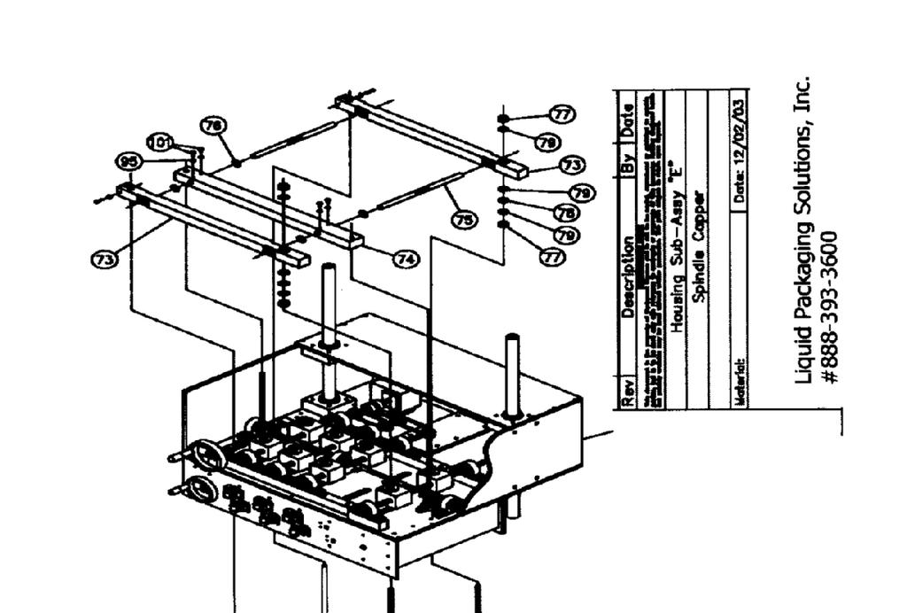
34 ASSEMBLY DRAWINGS On the following pages are the assembly drawings for the 4-station automatic spindle capper. Use them to verify assembly and for confirmation of part numbers, spare parts ordering, and related information. Page 34 of 40

35 Page 35 of 40

36 Page 36 of 40

37 Page 37 of 40


38 Page 38 of 40

39 Page 39 of 40
40 SPARE PARTS KIT Spare parts are available from and should be purchased directly through Liquid Packaging Solutions to ensure proper form, fit, and function to satisfy customer-specific applications. Liquid Packaging Solutions cannot guarantee the usability or suitability of any spare parts not purchased directly from Liquid Packaging Solutions. To order a spare parts kit or to contact the Liquid Packaging Solutions Sales Department, call (219) Refer to the Assembly Drawings on the previous pages to determine Part Numbers for individual parts Page 40 of 40
Vertical Stacking System for both Floor and Roof Lines. SQ-1 INTELLIGENT STACKERS. Operators Manual
 Vertical Stacking System for both Floor and Roof Lines. SQ-1 INTELLIGENT STACKERS Operators Manual FOREWORD This manual explains the proper maintenance of Square 1 Design Intelligent Stacking System as
CALIFORNIA TRIMMER MOWER MAINTENANCE MANUAL
 CALIFORNIA TRIMMER MOWER MAINTENANCE MANUAL 2 Table of Contents Section 1: General Information Page Handle Assembly Instructions 4 Maintenance All Models 6 Oil Change Procedures All Models 9 Height Adjustment
Tooling Assistance Center
 Safeguards are designed into this application equipment to protect operators and maintenance personnel from most hazards during equipment operation. However, certain safety precautions must be taken by
ASSEMBLY INSTRUCTIONS / OWNERS MANUAL AIR BIKE AB-1
 AIR BIKE AB- ASSEMBLY INSTRUCTIONS / OWNERS MANUAL IMPORTANT : READ ALL ASSEMBLY INSTRUCTIONS AND SAFETY PRECAUTIONS BEFORE USING THIS PRODUCT. REFERENCE ALL SAFETY GUIDELINES AND WARNING LABELS. RETAIN
Clutch Installation Guide
 Clutch Installation Guide 0 STOP! READ CAREFULLY BEFORE INSTALLING CLUTCH This clutch must be installed by a qualified installer. Improper installation or failure to replace or resurface the flywheel,
62 Deck Idler Kit High Speed
 Part No. 00 FORM NO. -899 6 Deck Idler Kit High Speed For Model 70 Serial No. 99000 to 99000 For Model 7 Serial No. 9900 to 99000 INSTALLATION INSTRUCTIONS Loose Parts Note: Use the chart below to identify
Contents. Overview Pinsetter Orientation...1-4
 Contents Overview...1-3 Pinsetter Orientation...1-4 Pinsetter Description...1-5 Ball Pit...1-5 Ball Cushion...1-5 Transport Band...1-7 Ball Accelerator...1-8 Pin Elevator...1-10 Distributor...1-14 Setting
Tech Note Truck 14 & 15.5 Twin Plate Cast Iron Type Installation Guidelines
 1. (14 & 15.5 ) Check condition of the flywheel. Grind to resurface or replace flywheel. Surface MUST BE machined or premature clutch failure can occur. Flywheel depth must be 2.938 (74.62mm) for 14 (350mm)
IMPORTANT! DO NOT THROW AWAY THE SHIPPING CARTON AND PACKING MATERIAL
 Operator s Manual IMPORTANT! DO NOT THROW AWAY THE SHIPPING CARTON AND PACKING MATERIAL ii Table of Contents Operator Safety... 1 Introduction... 2 Unpacking and Setup... 3 Unpacking... 3 Setup... 4 ROCKET
This is the Unpacking Guide for the Optibike Pioneer Allroad electric bicycle. The Guide provides information required to remove the Allroad from the
 This is the Unpacking Guide for the Optibike Pioneer Allroad electric bicycle. The Guide provides information required to remove the Allroad from the box and assemble it. If you have not assembled a bicycle
Wheel Horse. 44 Snowthrower. for 5xi Lawn and Garden Tractors. Model No & Up. Operator s Manual
 FORM NO. 8 Rev A Wheel Horse Snowthrower for 5xi Lawn and Garden Tractors Model No. 7966 890050 & Up Operator s Manual IMPORTANT: Read this manual, and your tractor manual, carefully. They contain information
FTFR Maintenance and Parts Manual SQ-1 FLOOR TRUSS FINISH ROLLER. Operators Manual
 FTFR Maintenance and Parts Manual SQ-1 FLOOR TRUSS FINISH ROLLER Operators Manual FOREWORD This manual explains the proper maintenance of Square 1 Design Floor Truss Finish Roller as well as the daily
INSTRUCTIONS. Fc. -1,<" SERIES ST-261 REGULATING UNLOADER VALVE
 INSTRUCTIONS Fc. -1,
Albany RR1000. Mechanical Installation Manual. PN: 6410T0029 Version - Rev: 04/23/2014. ASSA ABLOY Entrance Systems
 PN: 6410T0029 Version - Rev: 04/23/2014 Mechanical Installation Manual Albany RR1000 ASSA ABLOY Entrance Systems High Performance Door Solutions Tel: (770) 338-5000 975A Old Norcross Road Fax: (770) 388-5024
Procharger Stage II Intercooled Supercharger System (11-14 GT)
") Procharger Stage II Intercooled Supercharger System (11-14 GT) Installation Time: Approximately one day. Installed on 2012 Mustang GT 5.0/Manual Required Tools 3/8 Socket Set (Standard and Metric) 1/2
Procharger Stage II Intercooled Supercharger System (11-14 GT) Installation Time: Approximately one day. Installed on 2012 Mustang GT 5.0/Manual Required Tools 3/8 Socket Set (Standard and Metric) 1/2
Contents. Section 5: Adjustments Ball Detect Adjustment Transport Band Tension Adjustment
 Contents Section 5: Adjustments... 5-3 1. Ball Detect Adjustment... 5-3 2. Transport Band Tension Adjustment... 5-5 3. Transport Band Drive Belt Tension Adjustment... 5-7 4. Ball Cushion Adjustment...
INSTALLATION INSTRUCTIONS FOR DSP9600/9100 WHEEL BALANCER
 Form 5063T, 06-05 Supersedes Form 5063T, 02-04 INSTALLATION INSTRUCTIONS FOR DSP9600/9100 WHEEL BALANCER This document provides the information needed to install the DSP9600/9100 Wheel Balancer. NOTE:
MODEL 660 AUTOMATIC FASTENING CENTER OPERATOR S MANUAL
 MODEL 660 AUTOMATIC FASTENING CENTER OPERATOR S MANUAL Copyright: January 13, 2003 Revised: 080612 Serial No. 0506113. 1 TABLE OF CONTENTS INTRODUCTION..3 OPERATOR SAFETY... 3 SYSTEM REQUIREMENTS..4 INSTALLATION
Self-Adjust Clutch Installation Guide
 Self-Adjust Clutch Installation Guide 0 STOP! READ CAREFULLY BEFORE INSTALLING CLUTCH This clutch must be installed by a qualified installer. Improper installation or failure to replace or resurface the
Operations Manual Eagle 1000 Series Stretch Wrapper
 Operations Manual Eagle 1000 Series Stretch Wrapper Models A & B - 1 - READ ALL INSTRUCTIONS CONTAINED IN THIS MANUAL PRIOR TO MACHINE INSTALLATION! - 2 - Contents page 1. Machine Safety Information 1.1
XPS-ProFeed Shuttle SERVICE MANUAL. Revised:
 XPS-ProFeed Shuttle SERVICE MANUAL Revised: 9-14-15 RENA SYSTEMS INC. 910 East Main Street; Suite 200 Norristown, PA 19401-4110 Phone: (610) 650-9170 Fax: (610) 270-3947 Web Site: www.renausa.com SAFETY
Air / Hydraulic Floor Service Jack
 655 Eisenhower Drive Owatonna, MN 55060 USA Phone: (507) 455-7000 Tech. Serv.: (800) 533-6127 Fax: (800) 955-8329 Order Entry: (800) 533-6127 Fax: (800) 283-8665 International Sales: (507) 455-7223 Fax:
Installation Instructions Table of Contents
 Installation Instructions Table of Contents Pre- Installation of Garage Storage Lift 2 Layout the Garage Storage Lift 3 Installing the strut Channels 3 Install the Drive Assembly 5 Install the Drive Shaft
Assembly Instructions
 Assembly Instructions Part Number Description Model Approx. Assembly Time 99994-049 Cab Enclosure MULE SX 3-4 Hours WARNING Improper installation of this accessory could result in an accident causing serious
Not for Reproduction. BILLY GOAT AERATOR Owner's Manual AE401, AE401H, AE401H5T Replacement Parts. AE Owner s Manual TINE ROW KIT TINE KIT P/N
 BILLY GOAT AERATOR Owner's Manual AE401, AE401H, AE401H5T Replacement Parts TINE ROW KIT Complete tine row set for replacement of one complete row of tines. Includes mounting plates, spacer, and all hardware.
Marzocchi Suspension MZ III MZ III. Technical instructions
 Technical instructions Exploded view - MZ III - 100 Rif. Code Quantity Spare part list - MZ III - 100 Rif. Code Description Q.ty in the model Technical characteristics: Technical characteristics Single-crown
High Lift Transmission Jack
 655 Eisenhower Drive Owatonna, MN 55060 USA Phone: (507) 455-7000 Tech. Serv.: (800) 533-6127 Fax: (800) 955-8329 Order Entry: (800) 533-6127 Fax: (800) 283-8665 International Sales: (507) 455-7223 Fax:
COOKSON OWNER'S MANUAL
 COOKSON OWNER'S MANUAL FDO-A10 INDUSTRIAL DUTY FIRE DOOR OPERATOR R L I S T E D 3040233 US CONTROL PANEL SERIAL# OPERATOR SERIAL# 9001.DWG ECN 0959 REV 4 SPECIFICATIONS MOTOR TYPE:...INTERMITTENT HORSEPOWER:...1/8
servicing the swivel
 servicing the swivel The swivel seals and bearings require periodic replacement. This document describes how to determine which service procedure to use to service the swivel assembly, part number 101110.
Air / Hydraulic Floor Service Jack
 SPX Corporation 655 Eisenhower Drive Owatonna, MN 55060-0995 USA Phone: (507) 455-7000 Tech. Serv.: (800) 533-6127 Fax: (800) 955-8329 Order Entry: (800) 533-6127 Fax: (800) 283-8665 International Sales:
S-Drive Performance Trainer
 S-Drive Performance Trainer SERVICE MANUAl Table of contents CHAPTER 1: Serial number location... 1 CHAPTER 2: Important Safety instructions 2.1 Read and Save These Instructions... 2 2.2 Before Getting
Gantry System for both Floor and Roof Truss Lines SQ-1 INTELLIGENT GANTRY. Operators Manual
 Gantry System for both Floor and Roof Truss Lines SQ-1 INTELLIGENT GANTRY Operators Manual FOREWORD This manual explains the proper maintenance of Square 1 Design Gantry Rollers as well as the daily lubrication
Serial N... MX1 Chain Driven Pipe Cutting and Bevelling Machine Parts and Operating Manual
 Serial N... MX1 Chain Driven Pipe Cutting and Bevelling Machine Parts and Operating Manual Table of contents Section Description Page 1.0 General Information 2 2.0 Specification 2 2.1 General Specification
Gantry System for both Floor and Roof Truss Lines SQ-1 INTELLIGENT GANTRY. Operators Manual
 Gantry System for both Floor and Roof Truss Lines SQ-1 INTELLIGENT GANTRY Operators Manual FOREWORD This manual explains the proper maintenance of Square 1 Design Gantry Rollers as well as the daily lubrication
WALKIE HIGH LIFT HYDRAULIC SYSTEM
 WALKIE HIGH LIFT HYDRAULIC SYSTEM W30-40ZA [B453]; W20-30ZR [B455]; W25-30-40ZC [B454] PART NO. 1524251 2000 SRM 1025 SAFETY PRECAUTIONS MAINTENANCE AND REPAIR When lifting parts or assemblies, make sure
1 M-3000-H4 F150 4X4 Lowering Kit
 READ INSTRUCTIONS COMPLETELY THROUGH BEFORE STARTING. IT IS RECOMMENDED THAT INSTALLATION BE DONE BY A QUALIFIED MECHANIC. REPLACE ALL STOCK PARTS THAT ARE DAMAGED OR WORN. ALWAYS WEAR EYE PROTECTION.
Type 1051 and 1052 Size 33 Diaphragm Rotary Actuator
 Instruction Manual Type 1051 and 1052 Size 33 Diaphragm Rotary Actuator 1051 & 1052 Actuator Contents Introduction............................. 1 Scope of Manual........................... 1 Description................................
Fisher 2052 Diaphragm Rotary Actuator
 Instruction Manual 2052 Actuator Fisher 2052 Diaphragm Rotary Actuator Contents Introduction... 1 Scope of Manual... 1 Description... 1 Specifications... 4 Installation... 4 Actuator Mounting and Changing
Fisher 657 Diaphragm Actuator Sizes and 87
 Instruction Manual 657 Actuator (30-70 and 87) Fisher 657 Diaphragm Actuator Sizes 30 70 and 87 Contents Introduction... 1 Scope of Manual... 1 Description... 2 Specifications... 2 Installation... 3 Mounting
Agricultural Track Service Procedures Removal, Installation, Inspection and Alignment
 Agricultural Track Service Procedures Removal, Installation, Inspection and Alignment CNH STX Quadtrac Series CPB-0303 8/1/2006 Table of Contents Introduction...1 Track Terminology...1 General Tooling
SLM - Sealing Liquid Monitor INSTRUCTIONS FOR USE
 INSTRUCTIONS FOR USE 1/8 1 INSTALLATION SLM - Sealing Liquid Monitor INSTRUCTIONS FOR USE 1.1 Mounting The SLM has a mounting plate for simple installation. The SML can be mounted using a bolt already
THE SSD CHUTE IS INTENDED FOR THE DESTRUCTION OF SOLID STATE MEDIA ONLY! ATTEMPTING TO SHRED ROTATIONAL DRIVES WILL VOID WARRANTY!
 Security Engineered Machinery Model 0304 Comboo SSD/HDD Shredder OPERATION AND MAINTENANCE MANUAL POP 0065 Rev. 1 Revised: 10/21/2016 Security Engineered Machinery Co., Inc E Mail: Service@SEMSHRED.com
Front Drive System - Big Block Chevy Installation Instructions Big Block Chevy with AC & with PS
 Front Drive System - Big Block Chevy Installation Instructions Big Block Chevy with AC & with PS All American Billet Store (800) 764-0926 www.allamericanbilletstore.com Items needed for install Jack Jack
INSTALLATION AND OPERATING INSTRUCTIONS
 ASTRO ENVELOPE FEEDER AMC-2000-5 FOR RYOBI 3302 / ITEK 3985 (2 COLOR) INSTALLATION AND OPERATING INSTRUCTIONS INTRODUCTION Thank you for purchasing the Astro Envelope Feeder. It is fast, efficient, reliable,
Collector Drive for 44 Mower
 FORM NO. -80 Collector Drive for Mower Model No. 7955-990000 & Up Operator s Manual IMPORTANT: Read this manual, and your tractor manual, carefully. They contain information about your safety and the safety
CABINET REEL OPERATING INSTRUCTIONS
 CABINET REEL OPERATING INSTRUCTIONS MODELS 15, 25, 40 & 60 SERIES RAPID-AIR CORPORATION 4601 KISHWAUKEE ST. ROCKFORD, IL 61109-2925 Phone: (815) 397-2578 Fax: (815) 398-3887 Web Site: www.rapidair.com
OLYMPIAN MODEL 740 Operation and Service Manual
 OLYMPIAN MODEL 740 Operation and Service Manual P/N 133911-102 FCI MANUAL P/N 133865-001 Data herein has been verified and validated and believed adequate for the intended use. If the machine or procedures
Reproduction or other use of this Manual, without the express written consent of Vulcan, is prohibited.
 SERVICE MANUAL ELECTRIC BRAISING PANS (30 & 40 GALLON) VE30 VE40 ML-126849 ML-126850 VE40 SHOWN - NOTICE - This Manual is prepared for the use of trained Vulcan Service Technicians and should not be used
KidWalk KidWalk II Dynamic Mobility System
 OWNER S MANUAL KidWalk KidWalk II Dynamic Mobility System Manufactured By Prime Engineering A Division of Axiom Industries, Inc. Supplier Info 70111KWOM 2 TABLE OF CONTENTS This owner s manual is organized
Thermo-Bob 3 Installation Manual: KLR650E (2008 and newer)
") Thermo-Bob 3 Installation Manual: KLR650E (2008 and newer) Thank you for purchasing the Thermo-Bob 3 radiator bypass system for the KLR650. Since the KLR already has a doohickey, it seemed that this thingamabob
Thermo-Bob 3 Installation Manual: KLR650E (2008 and newer) Thank you for purchasing the Thermo-Bob 3 radiator bypass system for the KLR650. Since the KLR already has a doohickey, it seemed that this thingamabob
Air-Assist Service Jack Max. Capacity: 10 Tons
 Form No. 565786 Parts List & Operating Instructions for: 1511B Air-Assist Service Jack Max. Capacity: 10 Tons 109 67 66 68 77 69 70 78 95 94 107 106 108 26 71 72 72 93 X L 65 75 92 91 90 89 88 87 86 85
Checker Unload Checkstand Installation Instructions
 Front-End Checkouts Commercial Refrigeration Equipment Display Merchandisers Store Fixtures Checker Unload Checkstand Installation Instructions Attention Store Manager: Please find enclosed in this packet
Rekluse Motor Sports. The z-start Clutch DRZ400 KLX400. Installation Guide Copyright 2002 Rekluse Motor Sports z-start Revision 3.
 Rekluse Motor Sports The z-start Clutch DRZ400 KLX400 Installation Guide Copyright 2002 Rekluse Motor Sports z-start Revision 3.000 RMS160 KLX400 DRZ400 z-start Clutch 191-260 Manual Revision: 103105 Rekluse
( Versions Available)
") STYLE 494 ELECTRIC LADDER PIPE INSTALLATION, OPERATING AND MAINTENANCE INSTRUCTIONS ( Versions Available) The following is intended to provide the basic instructions for installation, operating and maintenance
STYLE 494 ELECTRIC LADDER PIPE INSTALLATION, OPERATING AND MAINTENANCE INSTRUCTIONS ( Versions Available) The following is intended to provide the basic instructions for installation, operating and maintenance
GANTRY ROLLER MANUAL MODELS: G14-24 G14-18 GR14-24 G2640 VOLUME 1, EDITION
 GANTRY ROLLER MANUAL MODELS: G14-24 G14-18 GR14-24 G2640 VOLUME 1, EDITION 5 7-13-04 FOREWORD This manual explains the proper maintenance of Klaisler Gantry Rollers as well as the daily lubrication and
XPS-ProFeed Shuttle SERVICE MANUAL. Revised:
 XPS-ProFeed Shuttle SERVICE MANUAL Revised: 1-14-15 RENA SYSTEMS INC. 910 East Main Street; Suite 200 Norristown, PA 19401-4110 Phone: (610) 650-9170 Fax: (610) 270-3947 Web Site: www.renausa.com SAFETY
INSTALLATION AND OPERATING INSTRUCTIONS
 ASTRO ENVELOPE FEEDER AMC-2000 INSTALLATION AND OPERATING INSTRUCTIONS INTRODUCTION Thank you for purchasing the Astro Envelope Feeder. It is fast, efficient, reliable, and is designed to give you many
Installation Manual. AutoSteer. Gleaner Combine. AutoGuide 2 Steer Ready. Supported Models A66 A76 R66 R76 S67 S77 PN: A
 Installation Manual AutoSteer Gleaner Combine AutoGuide 2 Steer Ready Supported Models A66 A76 R66 R76 S67 S77 PN: 602-0312-01-A LEGAL DISCLAIMER Note: Read and follow ALL Instructions in this manual carefully
NEW CRITICAL INSTRUCTIONS. MUST READ!
 HHX Ride-On Trowel Cross Shaft and Drive Pulley Installation Instructions The following instructions are intended to assist the user in the installation of a cross shaft and/or drive pulley. Please read
Wheel Horse. 36 Tiller. Model No & Up. Operator s Manual
 FORM NO. 8 9 Rev. A Wheel Horse 6 Tiller for Classic Garden Tractors Model No. 7970 690000 & Up Operator s Manual IMPORTANT: Read this manual carefully. It contains information about your safety and the
Collector Drive for 60 Mower
 FORM NO. -66 Collector Drive for 60 Mower Model No. 7965-990000 & Up Operator s Manual IMPORTANT: Read this manual, and your tractor manual, carefully. They contain information about your safety and the
SX1000 Service Manual SALES: CUSTOMER SERVICE:
 SX1000 Service Manual SALES: 800-278-3933 CUSTOMER SERVICE: 800-745-1373 Revision: August 1999 Table of Contents Section Page I. Overview 2 II. Troubleshooting Tables 3 III. Maintenance Procedures Procedure
INSTALLATION, OPERATION, AND MAINTENANCE MANUAL WELKER INJECTION PUMP
 INSTALLATION, OPERATION, AND MAINTENANCE MANUAL WELKER INJECTION PUMP MODEL SSO-8 DRAWING NUMBERS AD148CF AD148CG AD148CO AD148CQ AD500CA MANUAL NUMBER IOM-065 REVISION Rev. A, 8/17/2016 TABLE OF CONTENTS
ALL AMERICAN BILLET. Front Drive System - Small Block Ford Installation Instructions
 ALL AMERICAN BILLET Front Drive System - Small Block Ford Installation Instructions Small Block Ford with AC & PS All American Billet Store (800) 764-0926 www.allamericanbilletstore.com Items needed for
ISO1000R Service Manual SALES: CUSTOMER SERVICE:
 ISO1000R Service Manual SALES: 800-278-3933 CUSTOMER SERVICE: 800-745-1373 Revision: August 1999 Table of Contents Section Page I. Overview 2 II. Troubleshooting Tables 3 III. Maintenance Procedures Procedure
MicroCoat System Operating Manual MC4000 Series MC785M, MC785M-WF Spray Valves
 MicroCoat System Operating Manual MC Series MC785M, MC785M-WF Spray Valves A NORDSON COMPANY Introduction The MicroCoat System provides precise lubrication control for metal stamping operations. The MC
2106 HDCT-DUAL Belt Tracker
 2106 HDCT-DUAL Belt Tracker Features Stainless steel construction Two cylinders for added tracking power and neutral positioning External bearings Two mechanical remote sensors Filter regulator unit Tracker
IDENTIFICATION KLR.5100 Bagels bagger Left/right: right SERIAL NUM:
 Contents IDENTIFICATION... 1 Name and address of the manufacturer... 1 Declaration of conformity with standards of products... 1 Range of applications, intended use and general functions... 1 Dimensions
SITRANS F. Ultrasonic Flowmeters. Hi-Precision Mounts. Operating Instructions. Answers for industry.
 SITRANS F Ultrasonic Flowmeters Hi-Precision Mounts Operating Instructions Edition 12/2014 Answers for industry. Preliminary Instructions 1 Reflect Mount Mode 2 SITRANS F Ultrasonic Flowmeters Hi-Precision
Rekluse Motor Sports. The z-start Clutch GAS GAS. 200, 250, and strokes. 400 and strokes
 Rekluse Motor Sports The z-start Clutch GAS GAS 200, 250, and 300 2-strokes 400 and 450 4-strokes Installation Guide Copyright 2002-2004 Rekluse Motor Sports z-start Revision 3.000 RMS100 Gas Gas z-start
Control System. Part B, Section 1. This section covers the following unit configurations. Model Voltage 1, 2 Pump Piston (E, F, or G)
") Part B, Section 1 This section covers the following unit configurations. Model 3100 3400 3500 Voltage 1, 2 Pump Piston (E, F, or G) Manifold 4-Port (A) 6-Port (B or C) Control UniScan (1) B 1-0 B 1-1 Section
Part B, Section 1 This section covers the following unit configurations. Model 3100 3400 3500 Voltage 1, 2 Pump Piston (E, F, or G) Manifold 4-Port (A) 6-Port (B or C) Control UniScan (1) B 1-0 B 1-1 Section
SBCNNS. Abrasive Blast Cabinet Assembly & Operating Instructions
 SBCNNS Abrasive Blast Cabinet Assembly & Operating Instructions READ ALL INSTRUCTIONS AND WARNINGS BEFORE USING THIS PRODUCT. This manual provides important information on proper operation & maintenance.
TRAILER WINCH MODELS ST315 AND ST712. General Safety (Continued) Description. Unpacking. General Safety Information.
 Description. Unpacking. General Safety Information.") OPERATION AND MAINTENANCE MANUAL TRAILER WINCH READ CAREFULLY BEFORE ATTEMPTING TO ASSEMBLE, INSTALL, OPERATE OR MAINTAIN THE PRODUCT DESCRIBED. PROTECT YOURSELF AND OTHERS BY OBSERVING ALL SAFETY INFORMATION.
OPERATION AND MAINTENANCE MANUAL TRAILER WINCH READ CAREFULLY BEFORE ATTEMPTING TO ASSEMBLE, INSTALL, OPERATE OR MAINTAIN THE PRODUCT DESCRIBED. PROTECT YOURSELF AND OTHERS BY OBSERVING ALL SAFETY INFORMATION.
MINI MANIA REMOTE OIL COOLER INSTALLATION INSTRUCTIONS P/N NME1055
 MINI MANIA REMOTE OIL COOLER INSTALLATION INSTRUCTIONS P/N NME1055 Mini Mania s Cooper S Remote Oil Cooler Kit is designed to reduce operating temperatures by cooling the motor oil using an external radiator.
CBT25, 50 & 100 driveshaft
 CBT25, 50 & 100 driveshaft replacement 2 CBT driveshaft REPLACEMENT Revision History rev. level 01_03.13.2014 NOTE: due to the fact that a new machine (never exposed to seed treatment) was used to demonstrate
Philapack, LLC. Filler Machine Division
 Philapack, LLC Filler Machine Division 1840 County Line Rd. #203, Huntingdon Valley, PA 19006 Telephone (215) 322-2122: Fax (215) 355-1509 Web site: www.philapack.com Parts Email: parts@philapack.com Machine
WELDING POSITIONER OPERATION MANUAL MODEL TT-100 V1.0
 WELDING POSITIONER OPERATION MANUAL MODEL TT-100 Carefully read and understand these operation instructions before operating, inspecting, or servicing this product. This manual for use with Serial Numbers
Installation Instructions
 Preparing your vehicle to install your brake system upgrade 1. Rack the vehicle. 2. If you don t have a rack, then you must take extra safety precautions. 3. Choose a firmly packed and level ground to
Kysor On/Off Rear Air Fan Drive
 . Proper precautions must be taken to prevent personal injury from contact with moving parts, unintended engine start or other hazards present when working with powered equipment. Refer to the vehicle
A1062 & A1072 AUGER ASSEMBLY MANUAL. Read & understand all instructions pertaining to this auger prior to use!
 A1062 & A1072 AUGER ASSEMBLY MANUAL Read & understand all instructions pertaining to this auger prior to use! Safety Alert Watch for this ALERT Symbol. It identifies potential hazards to Personal SAFETY
RAMPAGE POWER LIFT RAMP
 RAMPAGE POWER LIFT RAMP INSTALLATION AND OPERATING INSTRUCTIONS (3/10/07) The Rampage Power Lift Ramp is the fast, easy, and safe way to load a motorcycle into a truck. One person can load or unload a
OEM TM-50 Quick Start Guide
 This quick start guide provides basic setup and operating instructions for the OEM TM-50. The intended use of the OEM TM-50 Taping Machine is to produce taped reels of individually sealed and consistently
OPERATIONAL INSTRUCTION OVERVIEW MAINTENANCE CHECKLIST
 OPERATIONAL INSTRUCTION OVERVIEW Operation Both manual and electrically powered winches develop tremendous forces; therefore, all backstops must be operated by qualified personnel only to avoid structural
INSTALLATION & OWNER S MANUAL
 1 of 18 INSTALLATION & OWNER S MANUAL (*Not including cab & other accessories) A/C Alternator Kit: Yamaha Drive & Drive2 P/N: 1ACYDR2DRK Recommended it be installed with Curtis Cab: Sandstone (p/n 1GCYD1-A,
JEEP JK4 STEP SLIDER INSTALLATION BD-SS-100-JK4
 JEEP JK4 STEP SLIDER INSTALLATION BD-SS-100-JK4 PARTS LIST QTY DESCRIPTION 1 Drivers Side Slider Assembly 1 Passenger Side Slider Assembly 1 Wiring Harness and Fuse 1 Double Sided Sticky Squares and Alcohol
ONYX VALVE CO MODEL DAC-PFO Installation & Maintenance
 ONYX VALVE CO MODEL DAC-PFO Installation & Maintenance OPERATION: (01-10) The Onyx series DAC-PFO pinch valve fails open on loss of air. This simple spring and air bag arrangement that drives a pair of
Installation Instructions. PowerFlex 700 Drive - Frame 8 Components Replacement
 Installation Instructions PowerFlex 700 Drive - Frame 8 Components Replacement Important User Information Solid-state equipment has operational characteristics differing from those of electromechanical
Radiator Kit kw Standby Generator Set
 Radiator Kit 299878 1200 kw Standby Generator Set These instructions are intended to finalize assembly of the radiator kit to the generator set. The generator set was fully assembled prior to testing and
SP0 & SP1 Knapsack Sprayer
 SP0 & SP1 Knapsack Sprayer We would like to congratulate you on the purchase of your new SP0. The sprayer that allows you the easiest, most comfortable way of carrying out your farm, garden, etc. projects
INSTALLATION AND OPERATING INSTRUCTIONS
 ASTRO ENVELOPE FEEDER AMC-2000 INSTALLATION AND OPERATING INSTRUCTIONS INTRODUCTION Thank you for purchasing the Astro Envelope Feeder. It is fast, efficient, reliable, and designed to provide many years
Super T QR20 INSTRUCTIONS GENERAL RULES
 INSTRUCTIONS GENERAL RULES 1. Where specified, assemble and disassemble the shock absorption system using the MARZOCCHI special tools only. 2. On reassembling the suspension system, always use new seals.
OPERATOR S MANUAL R-Series Roust-a-Bout
 December 2017 OPERATOR S MANUAL R-Series Roust-a-Bout! Before operatingthis lift, readand understandthis Operator s Manual. Become familiar with the potentialhazards of thisunit. Call SUMNER if youhaveanyquestions.
Procedure Replacing a Cover
 Procedure 7.1 - Replacing a Cover Cover Removal 1. Remove two screws, one each side, from the front of the top cover. Remove the top cover. See Diagram 7.1. Diagram 7.1 - RBK 815 Covers Top Cover Left
Maintenance Information
 (Dwg. MHP1539) 16600470 Edition 1 May 2007 Z Rail Aluminum and Steel Overhead Rail System Maintenance Information Save these Instructions The minimum maintenance required for a rail system requires inspection
Cylinder Installation Compression/Stripper, for Models, 22HF, 16HF, 1600 machines
 Knowledge Base Article Type: Instructions Cylinder Installation Compression/Stripper, for Models, 22HF, 16HF, 1600 machines Description: Instructions on How to properly install stripper beam and compression
KLAISLER MANUFACTURING CORPORATION
 KLAISLER MANUFACTURING CORPORATION FINISH ROLLER MANUAL MODELS: TR210-24 TR214-24 TR216-24 TR212-24 TR215-24 VOLUME 1, EDITION 4 7/15/04 FOREWORD This manual explains the proper maintenance of Klaisler
NILFISK BA 500 Service Manual
 NILFISK BA 500 Service Manual Model 66324400 12/94 Form Number 043023 TABLE OF CONTENTS Batteries...21 Brush Drive Belt Adjustment Or Replacement...7 Brush Drive Motor - Carbon brush Inspection... 8 Brush
WARCO CHEMAG SERIES GH FILTERS
 WARCO CHEMAG SERIES GH FILTERS High Performance Pleated & Bag Type Filtration Systems INSTALLATION, OPERATION, AND MAINTENANCE INSTRUCTIONS Thank you for your purchase of a WARCO Series GH Filtration System.
NEW CRITICAL INSTRUCTIONS. MUST READ!
 HHN Ride-On Trowel Cross Shaft and Drive Pulley Installation Instructions The following instructions are intended to assist the user in the installation of a cross shaft and/or drive pulley. Please read
INSTALLATION INSTRUCTIONS AMBASSADOR DRUM OVERHEAD SERIES 100 DUMBWAITER
 INSTALLATION INSTRUCTIONS AMBASSADOR DRUM OVERHEAD SERIES 100 DUMBWAITER The installation of Matot Drum Dumbwaiters should only be performed by qualified, experienced, and trained elevator installers.