Gantry System for both Floor and Roof Truss Lines SQ-1 INTELLIGENT GANTRY. Operators Manual
|
|
|
- Kelly McCoy
- 5 years ago
- Views:
Transcription

1 Gantry System for both Floor and Roof Truss Lines SQ-1 INTELLIGENT GANTRY Operators Manual
2 FOREWORD This manual explains the proper maintenance of Square 1 Design Gantry Rollers as well as the daily lubrication and periodic inspection procedures. Please read this manual thoroughly even though you may already be familiar with other Square 1 Design equipment, because it contains the most current information about the Square 1 Design Gantry Roller. This manual has been based on the standard Square 1 Design Gantry Roller. If you have any questions on modifications to your equipment, please contact Square 1 Design., or your sales representative. Square 1 Design reserves the right to make any changes or modifications to this manual or its Gantry Roller without giving notice and without incurring obligation. 1
3 CONTENTS Foreword Page 1 Before Initial Operation Page 3 General Description Page 4 Operation on Gantry Roller Page 5 Safety and Maintenance Page 5 Safety Guidelines Page 5-6 Maintenance Page 7 General Operation Page 7 Drive Train Adjustment Page 8 Chain Page 8 Roller Adjustment Page 8 Repair and Replacement Page 9 Electrical Page 9 Safety Switches Page 9 Control Panel Page 9 Motors Page 10 Mechanical Page 10 Drive Assembly Page 10 Chain Removal Page 10 Drive Sprocket Removal Page 10 Idler Sprocket Removal Page 10 Roller Page 11 Bearing Removal Page 11 Roller Removal Page 11 Warranty Information Page 12 Ordering Replacement Parts Page 13 Troubleshooting Page 14 PM Schedule and Details Page Grease Fitting Locations Page Bogie Block/Sensor Mount Page 21 Gantry Parts Diagram Page Replacement Parts List Page 26 2
4 BEFORE INITIAL OPERATION Please read this manual thoroughly. This will give you a better understanding of a Square 1 Design Gantry Roller and permit you to operate it correctly and safely. Identify and inform ALL employees who will operate or be near the Square 1 Design equipment of all concerns in this manual and on the production floor. It is very important from both the employers and manufactures standpoint that employee s safety comes above all else. The employer should make sure any employee who either operates or works near the equipment has been properly trained and given written notice of any and all safety concerns on the production floor. Always perform pre-operation checks and periodic maintenance. This will help prevent sudden malfunctions (due to poorly maintained equipment), improve work efficiency and help insure safe working conditions. 3
5 GENERAL DESCRIPTION The Square 1 Design Gantry Roller is an initial press machine. It is designed to be used in conjunction with a conveyor system to increase the assembly speed of finished wood trusses. The standard Square 1 Design Gantry Roller operates at a constant work speed of 120 feet per minute. The Square 1 Design Gantry Roller s heavy-duty design will allow it to press even the heaviest gauge plate very quickly and easily. The model # and serial # are located inside the Electrical panel of the Square 1 Design Gantry Roller. This information will be needed when contacting Square 1 Design for service information. Any information that is needed can be obtained by contacting you sales representative or: Square 1 Design & Manufacture Inc. 1 Clark Road Shelbyville, IN Phone: Fax: Sales@square1design.com 4
6 OPERATION OF THE GANTRY ROLLER The Square 1 Design Gantry Roller is very simple to operate and maintain. Square 1 Design suggests that operation of Square 1 Design equipment proceed in the following manor: 1. Everyone near the machine read the manual so general safety guidelines can be identified. 2. Everyone near the machine identify the safety devices and how they operate. 3. Perform daily, weekly, and monthly safety and maintenance analysis. 4. Correct any problems before operation of the equipment is started. 5. Check the area before beginning to be certain no employees are near the machine. SAFETY AND MAINTENANCE Employee safety is to key concern at Square 1 Design Manufacturing and should also be at your production facility. It is important to stress safety concerns around any type of production equipment because serious injury can occur without the proper training and supervision. Square 1 Design & Manufacture Inc. suggests that any employee who will operate or work around this equipment be given the opportunity to read this manual and receive training from qualified personnel at your facility. With the proper maintenance the equipment and work area become much safer. Square 1 Design & Manufacture Inc. has the following list of general safety and maintenance guidelines that should accompany any safety standards your company has established. SAFETY GUIDELINES 1. Cleanliness: The area surrounding the Square 1 Design Gantry Roller must be checked daily for any obstructions such as loose lumber or plates that could jam any area of the machine. 2. Operate new equipment with special caution: People are sometimes overconfident that the new equipment will work just like old equipment. This is not always true and a special caution should be taken around the new equipment. 3. Proper equipment use: Individuals working on or near the Square 1 Design Equipment, to prevent injury, should wear the proper equipment. Loose fitting clothing that can be caught in the machine or on the Gantry itself should NOT worn. Safety glasses MUST be worn for the protection of the employees. Employees without the Proper equipment should not be allowed near the Square 1 Design Gantry Roller. It is management s responsibility to enforce these guidelines, as well as the employees responsibility to make sure these guidelines are enforced. 4. Safety bars should be identified and proven to be in proper working order. All employees who will be working on or near the Square 1 Design Gantry Roller should know how the safety features work and confirm the machine is operating properly. If any employee notices the equipment may be malfunctioning in any way, a supervisor is to be notified and the power to the equipment is to be locked down until the problem can be rectified. 5. Disconnect and lock out all power sources before any maintenance or repair is to take place. It is important for the equipment s power to be disconnected and locked out to prevent accidental start-ups whether by another employee or workers error. 6. Follow the safety checklist Daily. The following checklist should be followed daily to ensure employees safety and a safe work environment. 5
7 SAFETY CHECKLIST Daily: A. Check safety bars to assure they move freely and easy. B. Check to make sure the machine stops properly when the safety bars/safety sensors are activated. C. Check for unusual noised, overheating, oil leaks, or other unusual machine characteristics. D. Check bearings for wear. E. Visually inspect motors and gearboxes for excessive dirt, heat, or vibration. F. Check gearbox oil levels (fill as required) G. Check ventilation openings to assure they are not clogged by dirt or dust. H. Check the area around the machine and track for cleanliness. I. Check to be sure everyone around the machine is wearing the proper equipment. J. Perform daily maintenance K. Be sure area is clear of people when starting the machine. Weekly: A. Check all bolts, nuts and set screws and tighten as require. B. Check drive train tension and adjust if necessary. C. Check oil level in drive unit and add proper amount if necessary. D. Use compressed air to remove sawdust and dirt build-up on the system and around the bearings.* *Wear eye protection when using the compressed air. 6
8 MAINTENANCE As mentioned earlier, keeping the equipment well maintained makes the work environment safer and allows reliable production for many years. Maintenance of the Square 1 Design Gantry Roller consists of lubricating the machine and chain, then tightening the nuts and bolts. The following is a maintenance schedule MUST be followed. Motors: The gearboxes on each motor have sight gauges for oil levels; insure that both motors are kept at the correct level. Chain: A non-detergent petroleum based oil every 18 hours should be used. Greased Fittings: General-purpose grease should be used every 8 hours or as needed. Nuts and Bolts: All nuts and bolts must be checked and tightened before operation of the Gantry Roller. Air Lines: All Air fittings and lines must be checked to provide the correct air volume. General Operation Operation of the Square 1 Design Gantry roller requires the operator to not only pay attention to his safety but to every other employee s safety as well. The entire work area must be inspected before operation of the machine. After the safety inspection, the operator should review the functions of the control buttons. There are 4 buttons on the standard gantry that allow the operator to run the machine. They are as follows: 1-Red Stop Button This button is used in situations where immediate breaking is required. When this button is pressed power is cut off to the motors. When this power is cut the fail-safe brakes activate stopping the drive shafts. Caution should be taken to stop the machine prior to an obstacle because the machine s weight may keep it rolling for a few seconds after the brakes have activated. 1-Forward Button This button moves the machine in forward motion. 1-Reverse Button This button moves the machine in reverse motion. Along with general machine operation the operator must also perform several daily operational adjustments. This section lists these adjustments and instructs the user on how to perform them. 7
9 DRIVE TRAIN ADJUSTMENT Square 1 Design Gantry Rollers have a drive train on both the left and right ends. All rollers are pre-set at Square 1 Design & Manufacture Inc. for a standard 2 x 4 and the chain tension is pre-set. Adjustment may be necessary, depending on actual moisture content and wood size. CHAIN ADJUSTMENT Begin by removing the bolt and lock washer that is holding the right end chain guard on (See Exhibit 3). Lift off the chain guard to allow enough space to work free of any obstructions. Loosen the two lock nuts holding the idler sprocket adjustment screw in place. Loosen the four nuts that mount the bearings to the machine The idler sprocket may then be adjusted by turning the threaded bolt clockwise to increase tension, counter clockwise to decrease tension. Care must be taken to keep the sprocket in line with the other sprockets. A little slack is desirable as it allows the chain links to seat themselves on the sprocket teeth. This will reduce wear on the sprocket and bearings. After the adjustment is complete, the locknut must be tightened to maintain proper tension. Retighten the four mounting bolts. Replace the chain guard and replace the lock washer and bolt. ROLLER ADJUSTMENT The Square 1 Design Gantry Roller has up to 4 ½ of total roller adjustment. To adjust the roller height, the drive chain idler sprocket adjustments must be loosened to allow plenty of slack in the drive chains. Care must be taken during roller adjustment to assure there is enough slack in the drive chains to allow full roller adjustment. To lower the roller, loosen the bottom roller adjustment nuts at both ends of the roller assembly. Begin by turning the top roller adjustment nuts counter clockwise to lower each end of the roller. Lower the roller until it comes to rest on top of the 2 x 4*. Tighten the bottom roller adjustment nuts. To raise the roller loosen the bottom roller adjustment nuts on both ends of the roller assembly (See Exhibit 5). Begin by turning the top roller adjustment clockwise to raise each end of the roller until a 2 x 4* can be inserted between the two rollers at each end. The roll will then need to be lowered slightly to put pressure on the wood. Tighten the bottom roller adjustment nuts. Readjust the chain drive to proper tension. Caution should be taken not to restart the machine without resetting the tension, as this will cause damage to the sprockets and the chain. *These are the instructions for a truss made from 2 lumber. For variations in thickness, the same directions can be followed using the same size lumber from which the truss is going to be made. 8
10 REPAIR AND REPLACEMENT In the case that a part of the machine is not working properly, this section lists how to remove and replace the correct part from Square 1 Design Gantry Roller. If parts are needed it is recommended that you contact Square 1 Design & Manufacture Inc. at the address listed on page 14. ELECTRICAL The following sections cover the electrical portions of the Square 1 Design Gantry Roller. Exhibits listed throughout this section contain a parts list and breakout of each item. Replacement parts are available as individual components or as complete units. Square 1 Design machines use SO multiconductor cable with sealed fittings. Any repairs should be done using the same materials. SAFETY SWITCHES There are 2 safety switches on each machine. Switches are available through Square 1 Design & Manufacture Inc. If they should need to be replaced contact Square 1 Design & Manufacture Inc. to make sure they are installed properly. REMOVAL OF SAFETY SWITCHES The safety switches are set to work with the safety bars. Remove the screws, nuts and lock washers holding the switch in place. Loosen the conduit locknut and unscrew the switch from the conduit. The wiring can now be disconnected and a new switch can be installed using the schematic as a guide. Reverse the instructions to reinstall the safety switches. Set actuator arm against the safety bar and tighten. Test and make sure safety bar is working properly before attempting to use the machine. CONTROL PANEL This unit is available as a complete control panel, a starter, or component parts for starters. Refer to the Electrical Schematic provided for parts list, breakout, and schematic to determine the information needed. REMOVAL OF CONTROL PANEL To remove the control panel, first disconnect the wiring inside the box to all motors, switches and input voltage. Remove the conduit locknuts inside and pull the conduit free from the panel. The control panel can now be removed by unfastening the 4 nuts and bolts mounting it to the mounting bracket. Reverse the order to install the panel. Refer to the schematic that came with your machine for the rewiring. Make sure the machine is operating correctly prior to running production. PENDANT SWITCH REMOVAL ALL 3 SWITCHES (Stop, Forward. and Reverse) can be replaced by using the same method. First remove the back plate off of the control pendant. Unscrew the switch from the plate. Remove the nameplate and push the switch through the panel. Reverse the procedure for re installing the switch to the front of the panel. Be extra cautious the buttons match the front panel when reinstalling (The stop button say Stop etc.) Refer to the schematic that came with your machine when making the connections. Make sure the machine is operating correctly prior to running production. 9
11 MOTORS The motors are available as a complete unit or in component parts. MOTOR REMOVAL Both motors (left and right drive) may be removed and replaced by the same method. Begin by disconnecting the electrical connections inside the connection box mounted on the side of the motor. Unscrewing 4 nuts holding the cover on the connection box can do this. The connection box cover is connected to the conduit. It can be set aside for reassembly. Remove the drive sprocket and the 4 bolts holding the motor mounting plate. Be careful as the motor and gearbox are very heavy and should be supported before removing the bolts. Reverse the procedure to remount the motor. Refer to the schematic provided to make the electrical connections. Make sure the machine runs properly before running the machine in production. MECHANICAL The following section covers the mechanical portion of the Square 1 Design Gantry Roller. Exhibits listed throughout this section contain parts lists and breakouts of common replacement parts. Some replacement parts are available as individual components and other are available only as a complete unit. Contact Square 1 Design & Manufacture Inc. or you sales representative for more information. DRIVE ASSEMBLY The drive assembly contains a number of component parts that are available as replacements. CHAIN REMOVAL Remove the chain guards. Locate the master link in the chain making sure it is in a location with easy access. Reduce the tension on the chain. Remove the master link by unsnapping the retaining clip and removing the link plate. Slide the master link out of the chain. Reverse the procedure for reassembly. Make sure the machine is operating correctly prior to running production DRIVE SPROCKET REMOVAL Remove the chain guards. Remove the chain from the drive train assembly. For the sprocket with a bushing: loosen the set screw in the key, remove the 3 hex head cap screws holding the bushing tight. Screw in 2 bolts into the 2 jack bolt holes. Tighten these bolts until the taper lock bushing is loose. It can be removed using the correct size puller. The sprocket will now slide off. For the sprocket with the setscrews: loosen both setscrews and slide off sprocket. It may be necessary to use fine grade emery paper to remove any butts from the shaft before reassembly. Reverse the procedure before reassembly. Make sure the machine is operating correctly prior to running production. IDLER SPROCKET REMOVAL Remove the chain guards. Remove the chain from the drive train. Remove the 4 bolts holding the bearings in place. To remove the sprocket, loosen the 2 set screws holding the shaft in position in the bearings. Reverse the procedure for reassembly and grease before start up. Make sure the machine is operating correctly prior to running production. 10
12 ROLLER The roller and bushings are replaceable items. Contact Square 1 Design for breakouts to determine the replacement parts required. BEARING REMOVAL Remove the chain guards. You will need to remove the roller sprocket before starting the bearing removal. Support the roll to prevent any moving. First, unfasten the 4 bolts A, B, C, and D. Remove the bearing side supports Remove the grease insert from the bearing block. Loosen the roll adjustment bolts. Pop the pins out of the adjustment rod to the bearing block. Unscrew the roll adjustment rod from the bearing block. Pull the bearing block off of the shaft with the correct tools. Check the bearing housing for damage. If the bearing has worn through the housing it will have to be replaced. To remove the bearing, use an arbor slightly smaller the O.D. of the bearing, and press it out of the housing. When pressing a new bearing into the housing, care must be taken to prevent damage to the bearing. After the bearing is installed in the housing, the grease holes must be drilled. Use the housing as a guide for the drilling. Remove all burrs from the I.D. of the bearing. Check the shaft for burrs before reassembly. Reverse the procedure to reassemble and reseal all fittings before start-up. Make sure the machine is operating correctly prior to running production. ROLLER REMOVAL Follow the directions to remove the bearing blocks. The roller can be removed by two different methods. To remove the roller from the top of the machine: disconnect all electrical from the top frame. Remove top guard from frame. Remove the nuts from the top of the bearing block. Remove the head assembly. Repeat this procedure for the other side. Place slings around the roller and attach a crane or hoist of proper capacity and lift the roller from the unit. Reverse the procedure to reassemble and grease all fittings before start-up. 11
13 WARRANTY Square 1 Design & Manufacture, Inc. warrants the equipment manufactured by it, to be free from defects in materials or workmanship for one (1) year from the date of delivery to the original purchaser. This is provided the equipment had been properly installed, operated, used, cared for, adjusted, cleaned and lubricated by the owner. All equipment claimed to be defective shall be returned to Square 1 Design & Manufacture, Inc. charges prepaid. All collect shipments will be refused. If upon inspection Square 1 Design & Manufacture Inc. determines to its satisfaction, that any part of the equipment is defective, Square 1 Design & Manufacture, Inc, at its option, correct the defect by repair or replacement. This warranty shall not apply if the original equipment had been altered or modified by any person other than Square 1 Design & Manufacture Inc. This Warranty shall not apply to starters, motors, gear reducers, or microswitches that are component parts of the equipment. Those separate component parts are governed by separate warranties of the respective component manufacturers, which warranties of the respective component manufacturers which warranties may be shorter than or longer than the one (1) year warranty granted by Square 1 Design & Manufacture, Inc. upon request by the owner. Any repairs are available from Square 1 Design & Manufacture Inc. upon request by owner. Any repair or replacement of such component parts shall be governed solely by manufacturer, and it shall be owner s responsibility to enforce any warranty claims directly with such component part manufacturer. EXCEPTION FOR THIS WARRANTY AS EXPRESSLY STATED, SQUARE 1 DESIGN & MANUFACTURE, INC. MAKES NO OTHER WARRANT EXPRESSED OR IMPLIED. ANY IMPLIED WARRANTY OF MERCHANTABILITY OR FITNESS FOR A PARTICULAR PURPOSE IS HEREBY DISCLAIMED. Square 1 Design & Manufacture Inc. shall not be liable for damages, direct, consequential, or incidental, or for delays, if such occur as a result of defects in material or workmanship. SQUARE 1 DESIGN & MANUFACTURE INC. PURCHASE DATE: MODEL NUMBER: SERIAL NUMBER: 12
14 ORDERING REPLACEMENT PARTS: Replacement parts can be ordered by calling, ing, or faxing: Square 1 Design & Manufacture Inc. 1 Clark Road Shelbyville, IN Phone: Fax: Sales@square1design.com When ordering parts, you must include the serial and model # s of your Square 1 Design Gantry Roller. 13
15 TROUBLESHOOTING There are several problems that can occur due to general vibration of the machine, or lack of maintenance. The following list the 4 common calls that Square 1 Design receives: Problem Cause Results The machine will not press the plates tight enough. The bogie wheels are not tight to the tube. Adjust the bogie wheels up to the bottom of the tube. One side of the machine starts before the other. The machine presses the plate good on one piece of wood at the joint, but not on the other. Intermittent electrical problems during operation of the machine. Your wood is smaller than previous wood. Chains are not adjusted properly. Wood is different sizes. A loose wire in the system. Adjust the roller down to match the wood. Retighten chains equally. This may have to be done several times up and down the track. Use uniform wood in the truss. Check all contacts in the box, push buttons, and safety switches. 14
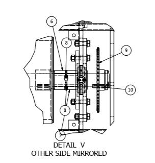
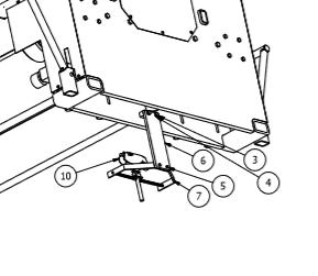
16 PM Schedule for Square 1 Design Intelligent Gantry System Prior to performing any PM s please follow your companies Lock Out/Tag Out Procedure to prevent injury. Monthly PM Schedule Grease Gantry. Check chain tension. Tighten down button head cap screws that hold skins in place. Hand check set screws located on sprockets Quarterly PM Schedule Semi-Annual PM Schedule Annual PM Schedule 26 Grease Fittings Per machine 13 per side Remove Covers located on the end of the Square 1 Design Intelligent Gantry to access Grease Fittings 1 on the roller per side. Located behind the large drive sprocket. (This is accessible once End Cover is removed.) 4 for the idler shafts per side, Located to the left and right of the large drive sprocket. (These are accessible once End Cover is removed.) 4 for the black wheels per side, fitting located on the bottom side of the bearing. (These are accessible from under the Gantry.) 2 for the slack adjuster. Located below the large drive sprocket. (These are accessible once the End Cover is removed) Check for Chain Tension Below the Drive Sprocket there are 2 bearing, a sprocket and a shaft that make up the Tensioner. If chain is too loose adjustment is made by loosing the 4 (1/2 Bolts that hold the bearings in place) Then adjusting down the ½ full thread bolts at the top of the weldment. Adjust evenly, when desired tension is applied to the chain, tights down jam nuts, and retighten the 4 bolts that hold the bearings in place. Tighten button head cap screws that hold skins in place. These are the black in color cap screws that hold the outside guards in place. Doing this will help prevent the loose of fasteners and help with noise. Hand Check set screws Check set screws in the sprockets, with an Allen Key just make sure that the set screws haven t vibrated loose. There are 2 per sprocket, and 2 per black drive wheel, with the exception of the drive sprocket that has 1 in the key way. While doing this also check the locking collars. Safety Sensor Bracket Verify that the bolts that hold the mounting bracket are tight, lack of doing so could cause that sensor to move and in turn throw off the sensors location. Quarterly PM Schedule All monthly PM s should be completed. Check to make sure that no electrical connections have come loose. 15

17 Verify that no air connections have come loose. Check 1-1/2 Jam nuts located above and below the headset and verify that they are tight. If these become loose it will allow for the roll to move up and down and not provide a good press of the plates. Verify that the 1 bolts and jam nuts located on the bogie blocks are tight. Annual PM Schedule All monthly PM s should be completed. All Quarterly PM s should be completed. 16


18 Location of Grease Fitting for the Roll Location of Grease Fittings for Idler Bearings 17


19 Location of Grease Fittings for Drive Wheels 18

20 Location of Grease Fittings for Slack Adjuster bearings. 19

21 Location of Roll Height Adjustment Jam Nut Location 20


22 Location of Bogie Block Bolts and adjustment bolts and Jam Nuts. Location of Bolts for Sensor Bracket 21
23 22
24 23
25 24
26 25
27 Part Number Location Page Location GA SM Bearing Block Page 24; Number 1 BEAR-0014 Bearing Adapter (Floor Truss) Page 24; Number 3 BEAR-0013 Bearing inside Bearing Block; (Floor Page 24; Number 4 Truss) *BEAR-0017 Bearing Inside Bearing Block; (Roof Truss) SPRO-0018 Sprocket on Roll Page 24; Detail V; Number 9 WHE-0010 Guide Wheel on Side of Gantry Page 25; Number 14 (Red) *WHE-0020 Guide Wheel on Side of Gantry Page 25; Number 14 (Black) BEAR-0015 Load Runner; Bottom of the Drive Page 25; Number 3 Tube WHE-0019 Drive Wheel (Green) Page 25; Number 7 *WHE-0021 Drive Wheel (Black) Page 25; Number 7 SPRO-0021 Sprocket Attached to the Drive Page 25; Number 11 Wheel Shaft BEAR-0002 Bearing that Holds Drive wheel Page 25; Number 2 Shaft; 4 Bolt Flange GA SM Shaft for Drive Wheel Page 25; Number 6 SHCO-0001 Locking Collars on Drive Wheel Page 25; Number 8 Shaft; 1 Piece *SCHO-0006 Locking Collars on Drive Wheel Page 25; Number 8 Shaft; 2 Piece ASME B NA4-2 Snap Ring on Drive Wheel Shaft Page 25; Number 12 GA SM Shaft for Slack Adjuster Page 26; Number 14 BEAR-0016 Bearing for Slack Adjuster; 2 Bolt Page 26; Number 12 Pillow Block SPRO-0020 Sprocket for Slack Adjuster Page 26; Number 16 GA SM Shaft for Idler Page 26; Number 6 BEAR-0007 Bearing for Idler Shaft; 2 Bolt Page 26; Number 2 Flange Bearing SPRO-0010 Sprocket for Idler Shaft Page 26; Number 8 Gantry Motor 7.5 HP Page 27; Detail E; Number 7 *Gantry Motor 10 HP Page 27; Detail E; Number 7 SPRO-0022 Sprocket on the Motor Page 27; Detail E; Number 8 **ELAC-0002 Electrical Collector with Connection Page 27; Number 10 Cable (Please Specify MFG for Re- Order) **ELAC-0125 Electrical Collector Tow Arm; Page 27; Number 7 Number 3 (Please Specify MFG for Re-Order) ELAC Button Pendant to Operate Gantry **ELAC-0006 Electrical Track Joint Cover **ELAC-0007 Electrical Track Anchor Clamp **ELAC-0101 Electrical Track Hanger Clamp *Please Specify as some SQ-1 Gantry Systems may vary. **Please Specify Manufacture of Electrical Track as some SQ-1 Gantry Systems may vary. 26
28 27
Gantry System for both Floor and Roof Truss Lines SQ-1 INTELLIGENT GANTRY. Operators Manual
 Gantry System for both Floor and Roof Truss Lines SQ-1 INTELLIGENT GANTRY Operators Manual FOREWORD This manual explains the proper maintenance of Square 1 Design Gantry Rollers as well as the daily lubrication
Vertical Stacking System for both Floor and Roof Lines. SQ-1 INTELLIGENT STACKERS. Operators Manual
 Vertical Stacking System for both Floor and Roof Lines. SQ-1 INTELLIGENT STACKERS Operators Manual FOREWORD This manual explains the proper maintenance of Square 1 Design Intelligent Stacking System as
FTFR Maintenance and Parts Manual SQ-1 FLOOR TRUSS FINISH ROLLER. Operators Manual
 FTFR Maintenance and Parts Manual SQ-1 FLOOR TRUSS FINISH ROLLER Operators Manual FOREWORD This manual explains the proper maintenance of Square 1 Design Floor Truss Finish Roller as well as the daily
GANTRY ROLLER MANUAL MODELS: G14-24 G14-18 GR14-24 G2640 VOLUME 1, EDITION
 GANTRY ROLLER MANUAL MODELS: G14-24 G14-18 GR14-24 G2640 VOLUME 1, EDITION 5 7-13-04 FOREWORD This manual explains the proper maintenance of Klaisler Gantry Rollers as well as the daily lubrication and
KLAISLER MANUFACTURING CORPORATION
 KLAISLER MANUFACTURING CORPORATION FINISH ROLLER MANUAL MODELS: TR210-24 TR214-24 TR216-24 TR212-24 TR215-24 VOLUME 1, EDITION 4 7/15/04 FOREWORD This manual explains the proper maintenance of Klaisler
RolsplicerTM. Maintenance Manual And Illustrated Parts List
 RolsplicerTM Maintenance Manual And Illustrated Parts List List of Illustrations Figure Page. Rolsplicer 3 2. Roller Adjustment 4 3. Rolsplicer 6 4. Lid Hold Down Assembly 8 5. Automatic Lid Speed Adjustment
READ AND SAVE THESE INSTRUCTIONS. Centrifugal Downblast Exhaust Fan Belt Driven for Roof & Wall Mounting
 READ AND SAVE THESE INSTRUCTIONS INSTALLATION, OPERATING INSTRUCTIONS & PARTS MANUAL Centrifugal Downblast Exhaust Fan Belt Driven for Roof & Wall Mounting Electrical wiring and connections should be done
OPERATIONS MANUAL LEVER CHAIN HOIST
 OPERATIONS MANUAL LEVER CHAIN HOIST IMPORTANT SAFETY INFORMATION Please read, understand and follow all safety information contained in these instructions prior to the use of this hoist. Retain these instructions
11 ½" MODEL SINGLE CHAIN CONVEYOR
 11 ½" MODEL SINGLE CHAIN CONVEYOR USER S MANUAL 11 ½" Chain conveyor Revision 2011-05-31 2 CONTENTS WARRANTY...3 FOREWORD...4 SAFETY PRECAUTIONS...5 ASSEMBLY INSTRUCTIONS...6 SPECIFICATIONS...6 ASSEMBLING
MODEL A OLD NORCROSS ROAD LAWRENCEVILLE, GA (770) TEL (770) FAX (877) TOLL FREE
 TEL (770) FAX (877) TOLL FREE") USER MANUAL RAPID-ROLL DOOR OWNER S MANUAL MODEL 230 975-A OLD NORCROSS ROAD LAWRENCEVILLE, GA 30045 (770) 338-5000 TEL (770) 338-5034 FAX (877) 925-2468 TOLL FREE Part # 6410T0009 Architectural Drawing
USER MANUAL RAPID-ROLL DOOR OWNER S MANUAL MODEL 230 975-A OLD NORCROSS ROAD LAWRENCEVILLE, GA 30045 (770) 338-5000 TEL (770) 338-5034 FAX (877) 925-2468 TOLL FREE Part # 6410T0009 Architectural Drawing
INSTALLATION INSTRUCTIONS
 INSTALLATION INSTRUCTIONS Thank you for purchasing ROLTECTM Electric Hopper Conversion. Agri-Cover, Inc. proudly manufactured this hardware using superior quality materials and workmanship. With proper
CONTENTS. VIKING PUMP, INC. A Unit of IDEX Corporation Cedar Falls, IA USA SECTION TSM 710.1
 TECHNICAL SERVICE MANUAL industrial heavy duty motor speed pumps SERIES 4076 AND 4176 SIZES hle, ate and ale SECTION TSM 710.1 PAGE 1 of 8 ISSUE B CONTENTS Introduction....................... 1 Safety
OWNER S MANUAL. LOEGERING th Street SE Casselton, ND USA Fax:
 OWNER S MANUAL TRAIL BLAZERS and D SERIES TRACKS LOEGERING 800-373-5441 15514 37 th Street SE 701-347-5441 Casselton, ND 58012 USA Fax: 701-347-4323 E-Mail: lmi@loegering.com Internet: www.loegering.com
Model 858-RH. Operating and Assembly Manual. Palmor Products Inc Serum Plant Road Thorntown, IN 46071
 Model 5-RH Operating and Assembly Manual Palmor Products Inc. 55 Serum Plant Road Thorntown, IN 6071 3/31/015 SAFETY RULES Remember, any power equipment can cause injury if operated improperly or if the
OWNER S MANUAL Z SERIES TRACKS. Rev. 355_05
 OWNER S MANUAL Z SERIES TRACKS Rev. 355_05 LOEGERING 800-373-5441 15514 37 th Street SE 701-347-5441 Casselton, ND 58012 USA Fax: 701-347-4323 E-Mail: lmi@loegering.com Internet: www.loegering.com Loegering
Before equipment use, please read this operation manual carefully. Serial Number: Date Purchased:
 Pushed & Geared Trolleys OPERATION MANUAL This operation manual is intended as an instruction manual for trained personnel who are in charge of installation, maintenance, repair etc. Before equipment use,
Operating and Assembly Manual
 Model 1080 Operating and Assembly Manual Midwest Equipment Manufacturing, Inc. 5225 Serum Plant Road Thorntown, IN 46071 08-02-16 SAFETY RULES Remember, any power equipment can cause injury if operated
TABLE OF CONTENTS DESCRIPTION. Safety Instructions & Safety Sign Locations Operating Instructions Assembly Instructions...
 TABLE OF CONTENTS DESCRIPTION PAGE Warranty... 1 Safety Instructions & Safety Sign Locations... 2 Operating Instructions... 3 Assembly Instructions... 5 500 & 600 Snowblower Drawings... 8 500 & 600 Snowblower
LEWIS WINDROWER OWNER / OPERATOR MANUAL
 LEWIS WINDROWER OWNER / OPERATOR MANUAL MODEL # WR-1 WINDROWER Manufactured by: LEWIS BROTHERS MANUFACTURING, INC. Post Office Box 146 Baxley, GA 31513 Tel: (912) 367-4651 Fax: (912) 367-3958 2-21-14 1
Outload Trough Roller Conveyor
 Outload Trough Roller Conveyor OWNER'S MANUAL 00003400 (8/99) Table of Contents Warranty Information.............................. Inside Front Cover Operator Qualifications / Sign Off Sheet..............................
WARRANTY REGISTRATION AND POLICY
 WARRANTY REGISTRATION AND POLICY Buhler Manufacturing products are warranted for a period of twelve (12) months from original date of purchase, by original purchaser, to be free from defects in material
HQZ & RBM MODEL LIFT & TRANSFERS
 Technical Documentation HQZ & RBM MODEL LIFT & TRANSFERS Each serial number is unique to that specific conveyor and provides mk North America with complete order details. The conveyor serial number is
B DUAL DRUM SANDER
 OWNER S MANUAL B2022-25 DUAL DRUM SANDER INDEX GENERAL SAFETY INSTRUCTIONS Page 3 Specifications Page 4 Features Page 5 Assembly Instructions Initial Assembly Page 6 Installing Abrasives Page 7 Adjusting
Twin Screw Undercar Conveyor
 Twin Screw Undercar Conveyor Owner s Manual #19015700 05-00 Table of Contents Operator Qualifications...................................... 1 Safety.................................................. 2-4
Flip - Up Conveyor. for 10" BeltVeyors OWNER'S MANUAL (12/00)
") Flip - Up Conveyor for 10" BeltVeyors OWNER'S MANUAL 19023100 (12/00) Table of Contents Warranty Information............................ Inside Front Cover Operator Qualifications........................................
Flip - Up Conveyor for 10" BeltVeyors OWNER'S MANUAL 19023100 (12/00) Table of Contents Warranty Information............................ Inside Front Cover Operator Qualifications........................................
Linear Actuator. Installation Manual. warranty installation parts list. Linear Actuator Installation Manual Page 1
 Linear Actuator Installation Manual warranty installation parts list January 2004 Linear Actuator Installation Manual Page 1 MA1221B12 Warranty Information Chore-Time Equipment ( Chore-Time ) warrants
PREMIER, MARINE, & STANDARD
 INSTA LLATION INSTRUCTION AND SERVICE MANUAL I TITAN 12" x 2" BRAKES FREE BACKING. UNI-SERVO. DUO-SERVO PREMIER, MARINE, & STANDARD Limited Warranty TITAN Inc. ("TITAN') warrants its products to be free
READ AND SAVE THESE INSTRUCTIONS. High Velocity Restaurant-Duty Utility Set Belt Driven for Roof Mounting
 READ AND SAVE THESE INSTRUCTIONS INSTALLATION, OPERATING INSTRUCTIONS & PARTS MANUAL High Velocity Restaurant-Duty Utility Set Belt Driven for Roof Mounting Electrical wiring and connections should be
580RK SERVICE GUIDELINES For coupling models: 580 & 580J
 580 Coupling THE FIRST NAME IN QUALITY COUPLINGS 580RK SERVICE GUIDELINES For coupling models: 580 & 580J BEFORE GETTING STARTED: This procedure should only be performed by a qualified mechanic. Measure
Read this entire manual before operation begins.
 Read this entire manual before operation begins. Record below the following information which is located on the serial number data plate. Serial No. Model No. Date of Installation Contents Specifications.............
TECHNICAL SERVICE MANUAL
 Electronic copies of the most current TSM issue can be found on the Viking Pump website at www.vikingpump.com TECHNICAL SERVICE MANUAL industrial heavy duty motor speed pumps SERIES 4076 AND 4176 SIZES
AC Electric Capstan Owner s Manual Installation and Operating Instructions
 AC Electric Capstan Owner s Manual Installation and Operating Instructions Model: HD2000-1A34-F-01 Serial Number: 123456 VAC _ Ø Hz Line Size: 1/2 CAUTION The final determination as to the suitability
Read this entire manual before operation begins.
 Read this entire manual before operation begins. Record below the following information which is located on the serial number data plate. Serial No. Model No. Date of Installation Contents Specifications.............
MBF-P 2040 PLASTIC MODULAR BELT CONVEYOR
 Technical Documentation PLASTIC MODULAR BELT CONVEYOR Each serial number is unique to that specific conveyor and provides mk North America with complete order details. The conveyor serial number is located
TABLE OF CONTENTS INSTALLATION & OPERATING INSTRUCTION MANUAL FOR MODEL PRC-- POWER ROLLER CONVEYOR
 TABLE OF CONTENTS INSTALLATION & OPERATING INSTRUCTION MANUAL FOR MODEL PRC-- POWER ROLLER CONVEYOR 1. INSTALLATION 2 1.1. GENERAL INSTALLATION 2 1.1.1. Building Connections 3 2. OPERATION 3 2.1. GENERAL
Airflo MANUFACTURING CO., INC.
 Airflo MANUFACTURING CO., INC. 365 UPPER OAKWOOD AVE, ELMIRA NY 14903 PHONE: 607-733-8284 / FAX: 607-733-0587 OPERATOR & PARTS MANUAL PSV-8L ELECTRIC SPREADER Visit our website at www.air-flo.com Contents
Read this entire manual before operation begins.
 Read this entire manual before operation begins. Record below the following information which is located on the serial number data plate. Serial No. Model No. Date of Installation Contents Specifications.............
20 Gauge Super-Speed. shoprpmachine
 Operator tor s s manual 20 Gauge Super-Speed 1 WARRANTY Our guarantee on the products we manufacture is limited to repair or replacement without charge, of any part found to be defective in materials or
KFM-P 2040 INCLINE BELT CONVEYOR
 Technical Documentation KFM-P 2040 INCLINE BELT CONVEYOR Each serial number is unique to that specific conveyor and provides mk North America with complete order details. The conveyor serial number is
Lincoln Hoist. Web Hoist Operating Manual. Lincoln Hoist
 Lincoln Hoist Web Hoist Operating Manual Lincoln Hoist Mfg. by Lincoln Precision Machining Company 121 Creeper Hill Road, P.O. Box 458, North Grafton, MA 01536 USA Toll Free (888) 306-7222 Phone (774)
INSTALLATION, OPERATION AND MAINTENANCE MANUAL WALL EXHAUST FANS BELT DRIVE XBL FANS
 INSTALLATION, OPERATION AND MAINTENANCE MANUAL WALL EXHAUST FANS BELT DRIVE XBL FANS The purpose of this manual is to aid in the proper installation and operation of the fans. These instructions are intended
Jet Fans. Instruction Manual READ AND SAVE THESE INSTRUCTIONS WARRANTY
 Jet Fans Instruction Manual READ AND SAVE THESE INSTRUCTIONS WARRANTY All Leader Fan products are guaranteed to be free from defects of workmanship or material and to function satisfactorily when properly
MG12K24T60V4 Mechanical Grapple
 170 State Route 271 Attachment Solutions MG12K24T60V4 Mechanical Grapple Operators Manual KENCO Mechanical Grapple Operation Manual 1 TABLE OF CONTENTS 170 State Route 271 Section I. General Information....
EV-2051-M Electric Motor. Operation and Maintenance Manual
 EV-2051-M Electric Motor Operation and Maintenance Manual Table of Contents Safety... 3 General...3 Safety Notices...6 Cautions, Warnings and Dangers...7 Cautions...8 Warnings...11 Dangers...13 Important
INSTALLATION, OPERATION AND MAINTENANCE MANUAL WALL EXHAUST FANS BELT & DIRECT DRIVE XB, HV, HVA, ADD, DDS, DDP
 INSTALLATION, OPERATION AND MAINTENANCE MANUAL WALL EXHAUST FANS BELT & DIRECT DRIVE XB, HV, HVA, ADD, DDS, DDP The purpose of this manual is to aid in the proper installation and operation of the fans.
LifeGuardLift. LifeGuard Power Lift Model #100287A OWNERS MANUAL. Rev: 2/14/11
 LifeGuardLift OWNERS MANUAL LifeGuard Power Lift Model #100287A Rev: 2/14/11 Table of Contents 1. ASSEMBLY INSTRUCTIONS A. Lift Assembly B. Setup C. Disassembly 2. CONTROL SYSTEM A. Batteries B. Battery
Visit Our Our Our Web Site at:
 Visit Our Our Our Web Site at: ww w ww w w w w. l o c k f o rr r m e r r r. c o m 711 OGDEN AVENUE, LISLE, ILLINOIS 60532-1399 Phone (630) 964-8000 Fax (630) 964-5685 09-1998 Operator tor s manual 20 Gauge
OPERATOR MANUAL Combo Belt Conveyor
 1 OPERATOR MANUAL Combo Belt Conveyor Document No. 11-01, Rev., 0816 2 WARNINGS THIS CONVEYOR IS DESIGNED FOR A SPECIFIC APPLICATION. CHECK FRAME AND METAL BELT FOR DAMAGE DURING SHIPMENT. READ THE MANUAL
INSTALLATION INSTRUCTIONS AND OWNER S MANUAL
 INSTALLATION INSTRUCTIONS AND OWNER S MANUAL Thank you for purchasing the AlloyCover from WeatherTech. Manufactured with pride using superior quality materials and workmanship. With proper care, your cover
READ AND SAVE THESE INSTRUCTIONS. Centrifugal Upblast Exhaust Fan (Standard & High Pressure Exhaust) Belt Driven for Roof & Wall Mounting
 Belt Driven for Roof & Wall Mounting") READ AND SAVE THESE INSTRUCTIONS INSTALLATION, OPERATING INSTRUCTIONS & PARTS MANUAL Centrifugal Upblast Exhaust Fan (Standard & High Pressure Exhaust) Belt Driven for Roof & Wall Mounting Electrical wiring
READ AND SAVE THESE INSTRUCTIONS INSTALLATION, OPERATING INSTRUCTIONS & PARTS MANUAL Centrifugal Upblast Exhaust Fan (Standard & High Pressure Exhaust) Belt Driven for Roof & Wall Mounting Electrical wiring
Positive Displacement Pump
 www.conairgroup.com U S E R G U I D E UGC028-1105 Positive Displacement Pump Models PD 3. 5, 7.5, 10, 15 and 25 Corporate Office: 724.584.5500 l Instant Access 24/7 (Parts and Service): 800.458.1960 l
TABLE OF CONTENTS. Warranty Disclaimers Delivery Checklist After Sale Checklist Safety Set Up... 8
 TABLE OF CONTENTS Pickett Equipment Warranty... 2 Warranty Disclaimers... 3 Delivery Checklist... 4 After Sale Checklist... 4 Safety... 5-7 Set Up... 8 Machine Adjustments and Operation... 9 Maintenance
AGRI-COVERTM SWITCH CONTROL INSTRUCTIONS
 AGRI-COVERTM SWITCH CONTROL INSTRUCTIONS Use these instructions in place of the rocker switch and solenoid sections in your roll tarp or ROLTECTM Electric Hopper Conversion instructions. Some installs
INSTALLATION INSTRUCTIONS
 INSTALLATION INSTRUCTIONS Thank you for purchasing TONNOSPORT Roll-Up Cover. Agri-Cover, Inc. proudly manufactured this cover using superior quality materials and workmanship. With proper care, your cover
RollSeal 1733 County Road 68 Bremen, Alabama Part No Rev Owner s Manual RS-Divider Curtain
 1. 2. 7 3. 4. RollSeal 1733 County Road 68 Bremen, Alabama 35033 256-287-7000 Part No 4801-5176 Rev 12-11-17 Owner s Manual RS-Divider Curtain Table of Contents 1 Warnings (Avertissements)... 3 2 Limited
48" and 52" Hyflo Fans Installation and Operators Instruction Manual
 48" and 52" Hyflo Fans Installation and Operators Instruction Manual Thank You The employees of Chore-Time Equipment would like to thank your for your recent Chore-Time purchase. If a problem should arise,
INSTALLATION, OPERATION & MAINTENANCE MANUAL AXIAL UPBLAST FANS RTA, RWTA, RHTA, RB, RD, RTA SH
 INSTALLATION INSTALLATION, OPERATION & MAINTENANCE MANUAL AXIAL UPBLAST FANS RTA, RWTA, RHTA, RB, RD, RTA SH The purpose of this manual is to aid in the proper installation and operation of the fans. These
Spring-Engaged/Hydraulically-Released BD Caliper Brake. (i) MTY (81) QRO (442) MEX (55)
 MTY (81) QRO (442) MEX (55)") Spring-Engaged/Hydraulically-Released BD Caliper Brake (i) FORM NO. L-07-E-0300 In accordance with Nexen s established policy of constant product improvement, the specifications contained in this manual
Spring-Engaged/Hydraulically-Released BD Caliper Brake (i) FORM NO. L-07-E-0300 In accordance with Nexen s established policy of constant product improvement, the specifications contained in this manual
Hydraulic Bead Breaker Kit
 Hydraulic Bead Breaker Kit Owner s Manual WARNING: Read carefully and understand all ASSEMBLY AND OPERATION INSTRUCTIONS before operating. Failure to follow the safety rules and other basic safety precautions
NEW EQUIPMENT WARRANTY
 NEW EQUIPMENT WARRANTY We warrant that this equipment from U.S. Stoneware Corporation is within stated specifications and is free from defects in materials and workmanship. Our obligation under this warranty
NEW EQUIPMENT WARRANTY
 NEW EQUIPMENT WARRANTY We warrant that this equipment from U.S. Stoneware Corporation is within stated specifications and is free from defects in materials and workmanship. Our obligation under this warranty
48" Vanguard Slant Wall and Cone Belt Drive Fans Installation & Operator s Instruction Manual
 8" Vanguard Slant Wall and Cone Belt Drive Fans Installation & Operator s Instruction Manual MV1600-1C 9/99 MV1601-9 9/99 March 2002 Chore-Time Warranty Belt Drive Fans Chore-Time Warranty Chore-Time Equipment
1000 lb. Adjustable Gantry Crane
 1000 lb. Adjustable Gantry Crane Owner s Manual WARNING: Read carefully and understand all ASSEMBLY AND OPERATION INSTRUCTIONS before operating. Failure to follow the safety rules and other basic safety
GUF-P MINI BELT CONVEYOR
 Technical Documentation GUF-P MINI BELT CONVEYOR Each serial number is unique to that specific conveyor and provides mk North America with complete order details. The conveyor serial number is located
INSTRUCTION MANUAL FOR MODEL PRC POWER ROLLER CONVEYOR
 INSTRUCTION MANUAL FOR MODEL PRC POWER ROLLER CONVEYOR - 1 - TABLEOFCONTENTS 1. OPERATION 3 1.1. GENERAL DESCRIPTION 3 1.2. OPERATION 3 1.2.1. GENERAL INSTRUCTIONS 3 2. MAINTENANCE 4 2.1. CHAIN TAKEUP
INSTALLATION, INSTRUCTION AND SERVICE MANUAL
 INSTALLATION, INSTRUCTION AND SERVICE MANUAL Actuator/Brake/Trailer Dealer Please provide to consumer. Consumer Read and follow instructions. Keep with trailer for reference. Page 1 of 7 1. Introduction...
2000 lb Adjustable Gantry Crane
 2000 lb Adjustable Gantry Crane Owner s Manual WARNING: Read carefully and understand all ASSEMBLY AND OPERATION INSTRUCTIONS before operating. Failure to follow the safety rules and other basic safety
INSTALLATION INSTRUCTIONS
 INSTALLATION INSTRUCTIONS Thank you for purchasing VANISH Roll-Up Cover. Agri-Cover, Inc. proudly manufactured this cover using superior quality materials and workmanship. With proper care, your cover
ATV TRACK KIT. Operator s Manual Installation Instructions Service Instructions Replacement Parts List. Effective Date: October, 2012
 p/n 2258-642 ATV TRACK KIT Operator s Manual Installation Instructions Service Instructions Replacement Parts List Track Assembly Kits (p/n 1436-204) Mounting Assembly Kits (p/n 1436-205) 1436-815) Effective
TECHNICAL SERVICE MANUAL
 TECHNICAL SERVICE MANUAL HEAVY-DUTY bracket mounted PUMPS SERIES 4193 AND 493 SIZES GG - AL SECTION TSM 154 PAGE 1 of 10 ISSUE C CONTENTS Introduction....................... 1 Special Information...................
610 BUSHEL MANURE SPREADER
 610 BUSHEL MANURE SPREADER RODA MANUFACTURING 1008 LOCUST ST. HULL, IA. 51239 Art s-way Manufacturing 712-439-2366 Co., Inc. Hwy 9 West - PO Box 288 WWW.RODAMFG.COM Armstrong, IA. 50514 U.S.A 2 INTRODUCTION
BELOW-THE-HOOK & MATERIAL HANDLING EQUIPMENT
 BELOW-THE-HOOK & MATERIAL HANDLING EQUIPMENT lifting EQUIPMENT Tongs HBTF Bar Tong Fixed... Page 62 TONGS HBTA Bar Tong Adjustable... Page 63 lifting EQUIPMENT HBTF BAR TONG FIXED FEATURES This style of
Operator's Manual. VC-60 & VC-60 Plus Harper Industries, Inc. 7/03 Part No
 Operator's Manual VC-60 & VC-60 Plus 2003 Harper Industries, Inc. 7/03 Part No. 970066 Thank you for purchasing a Harper/Goossen Verti-Cutter. As with all Harper/Goossen products, the Harper/Goossen Verti-Cutter
CRD610 Automatic Fitting Inserter
 CRD610 Automatic Fitting Inserter OPERATIONS MANUAL VERSION 1.2 LAST EDITED 12.12.2018 cleanroomdevices.com 1 Table of Contents Title Page. 1 Table of Contents...2 1.0 General Product & Safety Information....3
DRAGO. Corn Header Manual f HEADSIGHT.COM
 DRAGO Corn Header Manual 09020801f HEADSIGHT.COM 574.546.5022 About Headsight Headsight Contact Info Headsight, Inc. 4845 3B Road Bremen, IN 46506 Phone: 574-546-5022 Fax: 574-546-5760 Email: info@headsight.com
Wood Chipper Model C550M Operator's Manual
 Wood Chipper Model C550M Operator's Manual THIS MANUAL MUST BE READ AND UNDERSTOOD BEFORE ANYONE OPERATES THIS MACHINE! Manual# 990023 Revised 01/2010 YOU MUST FILL OUT YOUR WARRANTY REGISTRATION TO ACTIVATE
RED23305 Owner s Manual
 RED23305 Owner s Manual 5 foot, 3-Point Mounted Snow Blower 270 West Park Avenue Huron, SD 57350 866-526-5682 Serial Number: Date of Purchase: Red Devil Snow Blower See Figure 1. 1. The Red Devil Snow
CRUSTBUSTER OWNER / OPERATOR MANUAL
 CRUSTBUSTER OWNER / OPERATOR MANUAL MODEL # CB-1 CRUSTBUSTER Manufactured by: LEWIS BROTHERS MANUFACTURING, INC. Post Office Box 146 Baxley, GA 31513 Tel: (912) 367-4651 Fax: (912) 367-3958 5-2-17 1 INTRODUCTION
INSTALLATION INSTRUCTIONS
 INSTALLATION INSTRUCTIONS Thank you for purchasing a LOMAX TM Hard Tri-Fold or Professional Series Cover. Agri-Cover, Inc. proudly manufactured this cover using superior quality materials and workmanship.
INSTALLATION INSTRUCTIONS
 INSTALLATION INSTRUCTIONS Thank you for purchasing ACCESS Original Roll-Up Cover. Agri-Cover, Inc. proudly manufactured this cover using superior quality materials and workmanship. With proper care, your
Hydraulic Furniture Movers
 Hydraulic Furniture Movers Owner s Manual WARNING: Read carefully and understand all ASSEMBLY AND OPERATION INSTRUCTIONS before operating. Failure to follow the safety rules and other basic safety precautions
Heavy Duty Engine Cranes
 Heavy Duty Engine Cranes Operating Instructions & Parts Manual Model Number Atd-7484 Atd-7485 (Foldable Legs) Capacity 2 Ton 2 Ton Model Atd-7484 Model Atd-7485 Atd Tools Inc. 160 Enterprise Drive, Wentzville,
Installation, Operating and Maintenance Instructions. Rotating Machine Screw Actuators. With Parts List Publication Part No.
 Installation, Operating and Maintenance Instructions With Parts List Publication Part No. SK-2389-R1 Rotating Machine Screw Actuators 1/4 Through 1-Ton Capacity Caution This manual contains important information
"WHERE TUBING AND FITTINGS COME TOGETHER"
 CLEAN ROOM DEVICES, LLC "WHERE TUBING AND FITTINGS COME TOGETHER" CRD200SS TUBE EXPANDER OPERATIONS MANUAL VERSION 4.3 LAST EDITED 06.17.15 cleanroomdevices.com Table of Contents Table of Contents....1
MODEL NO & UP SAFETY INSTRUCTIONS. Keep this Operator s Manual in the plastic tube behind the operator seat.
 FORM NO. 94-7276 MODEL NO. 41026-60101 & UP OPERATOR S INSTRUCTIONS HOSE REEL KIT To assure maximum safety, optimum performance, and to gain knowledge of the product, it is essential that you or any other
Compressor Clutch Replacement Procedure
 Clutch Replacement Procedure P-1401-WE 819-0316 Installation Instructions An Altra Industrial Motion Company Warner Replacement Clutches for the following compressors: Denso 6E171 10P15 6P148 6C17 Ford
Installation Instructions
 85-4592 rev. 08 02-18 Installation Instructions Thank you for purchasing our sway bar kit. Please read through these instructions before installation. Auxiliary Rear Anti-Sway Bar Kit for Ford F53 part
Operating and Maintenance Instructions
 1500 Tube Leak Test Gun - Vacuum Tube & Pipe Cleaners Tube Testers Tube Plugs Tube Removal Tube Installation Operating and Maintenance Instructions www.elliott-tool.com Table Of Contents Introduction...
Electric Actuator Installation, Operation & Maintenance Manual
 ICI Indelac Controls, Inc. Electric Actuator Installation, Operation & Maintenance Manual 6810 Powerline dr.-florence, Ky. 41042 - Telephone 859-727-7890, Tool free 800-662-9424 Fax. 859-727-4070, e-mail:
Straight-Bore Clutch LSCC-32, 44, 54
 Straight-Bore Clutch LSCC-32, 44, 54 1 In accordance with Nexen s established policy of constant product improvement, the specifications contained in this manual are subject to change without notice. Technical
Operations Manual Eagle 1000 Series Stretch Wrapper
 Operations Manual Eagle 1000 Series Stretch Wrapper Models A & B - 1 - READ ALL INSTRUCTIONS CONTAINED IN THIS MANUAL PRIOR TO MACHINE INSTALLATION! - 2 - Contents page 1. Machine Safety Information 1.1
8" - 12" Hydraulic Steel Squeeze Off Tool
 8" - 12" Hydraulic Steel Squeeze Off Tool ECN 19130 C812S Hydraulic Steel Squeeze Off Tool for Steel Pipe Page 1 of 8 This Footage Tools C812S Steel Squeeze Off Tool is sold with one pump configuration
ROLLER SPREADER. Model - #171A-M Lee's Chapel Road Browns Summit, NC Tel: (800) Fax: (336) Web:
 Fax: (336) Web:") ROLLER SPREADER Model - #171A-M2 2949 Lee's Chapel Road Browns Summit, NC 27214 Tel: (800)-901-8037 Fax: (336)-375-1112 Web: www.jltclamps.com G@MAN#171A-M2-R1 2/11/04 SAH INTRODUCTION Company Introduction
ROLLER SPREADER Model - #171A-M2 2949 Lee's Chapel Road Browns Summit, NC 27214 Tel: (800)-901-8037 Fax: (336)-375-1112 Web: www.jltclamps.com G@MAN#171A-M2-R1 2/11/04 SAH INTRODUCTION Company Introduction
Owner s Manual Gantry Cranes
 Owner s Manual Gantry Cranes Fixed Height Gantry Crane MODEL NUMBER: SERIAL NUMBER: CAPACITY IN TONS: Telescoping Gantry Crane Bushman Equipment, Inc. 262-790-4200, 800338-7810, Fax 262-790-4200 www.bushman.com
specifications and is free from defects in materials and workmanship.
 We warrant that this equipment from U.S. Stoneware Corporation is within stated specifications and is free from defects in materials and workmanship. Our obligation under this warranty is limited to repairing
Raydot LLC 24 Actuator (115 VOLT)
") Installation, Operation & Parts Manual Read carefully the information provided. Retain manual for future reference. Raydot LLC 24 Actuator (115 VOLT) 145 Jackson Ave. S. Cokato, MN 55321-USA (320) 286-2103
Installation, Operation & Parts Manual Read carefully the information provided. Retain manual for future reference. Raydot LLC 24 Actuator (115 VOLT) 145 Jackson Ave. S. Cokato, MN 55321-USA (320) 286-2103
ZRF-P 2040 TIMING BELT CONVEYOR
 Technical Documentation ZRF-P 2040 TIMING BELT CONVEYOR Each serial number is unique to that specific conveyor and provides mk North America with complete order details. The conveyor serial number is located
ECONOMIZER FAN. Receiving and Inspection
 ECONOMIZER FAN Economizer Fans INSTALLATION, OPERATION AND MAINTENANCE MANUAL This publication contains the installation, operation and maintenance instructions for standard units of the Economizer Fan
O:\Manuals\SHAVING MILLS\30 INCH\SHAVING MILL MANUAL..30 INCH P.W doc 1
 O:\Manuals\SHAVING MILLS\30 INCH\SHAVING MILL MANUAL..30 INCH P.W.10.30.2017.doc 1 TABLE OF CONTENTS 30 SHAVING MILL COVER & TABLE OF CONTENTS......Pages 1 2 STATEMENT OF FACT.... Page - 3 MACHINE REGISTRATION.....Page
MiTek Machinery Division. Service Bulletin
 MiTek Machinery Division Service Bulletin Machinery Affected: Document: Title: Applies To: Distribution: RoofGlider Press SB198 Redesigned Push Bar Push Bars Manufactured With Gas Spring and Clamp-Style