Pneumatics products Logic elements, Position / Detectors Electro-pneumatic valves
|
|
|
- Lydia Barker
- 5 years ago
- Views:
Transcription

1 Pneumatics products Logic elements, Position / Detectors Electropneumatic valves Switching Control systems Directional control CH 5453 Busslingen


2 For over 50 years, Crouzet, a subsidiary of Schneider Electric, has established a reputation for providing microcontrol products, micromotors and position sensors. Read on to discover Crouzet's complete offer of Pneumatic products for industrial and explosive atmospheres. Always one step ahead of market trends and customer requirements, Crouzet is continually developing its range of both standard and customised automation components and solutions to cover all the latest commercial and industrial applications and meet the needs expressed by manufacturers of automated equipment and machinery. Throughout the world, Crouzet the adaptation specialist provides you with technical and industrial expertise to ensure seamless integration, whatever the equipment environment or operating requirements of the machine. Crouzet belongs to Custom Sensors & Technologies (CST) which is made up of the leading brands of Kavlico, Crydom as well as the former divisions of BEI Technologies, including Newall and Systron Donner. In addition to the Microcontrol products in this brochure, CST also offers an extensive range of products and solutions in detection, control and motorisation. The result? Even better service and technical choice for our customers. Ecodesign is central to the company's "Offer Creation Process", the aim of which is to design products and services that correspond as closely as possible to customers' requirements and reduce their environmental impact throughout their life cycle. Customer satisfaction will always be our prime objective. To this end, we rely on standards ISO 9001 and ISO14001 to ensure that our design, industrialisation, manufacturing and commercialisation processes correspond to our customers' requirements. All Crouzet products are fully compliant with the RoHS directive CH 5453 Busslingen

3 Expertise for all your applications Crouzet's Pneumatic expertise provides you with an offer to meet all your automation system requirements, including systems for explosive atmospheres. The quality of the Pneumatic components is based on a rigorous organisation which meets all current European and international directives, standards and approvals. All our products are fully compliant with the RoHS directive and embody an ecodesign concept. The Pneumatic offer is the result of the implementation of Crouzet applications and expertise: v Listening to and analysing your requirements v Expertise in the associated applications: mechanical, electronic, sensors, etc. v Prototyping and industrialisation v Tests v Standardisation and certification (IEC, EN, ULCSA, ATEX, etc.) v Equipment which is responsive and effective v International logistics and after sales support. Crouzet has developed broad expertise in ensuring that your specific needs are taken into account. Thanks to this expertise, we are continuously developing our standard products to create solutions tailored to your requirements. Some relevant areas Water treatment, chemical factories, silos, gas storage, ports, refineries, paper industry, paint factories, vehicles (if used in ATEX conditions), etc. CH 5453 Busslingen


4 Pneumatic offer for use in industrial and explosive atmospheres This guide has been designed to help you quickly identify the appropriate products for your requirements.most of our pneumatic components are available in a standard range and a range for use in explosive atmospheres (ATEX): this information is given in the righthand column on each page. Industrial range The standard range of pneumatic components is designed to meet requirements for industrial applications. The operating characteristics (pressure, flow rate, service life, etc.) have been optimised to best meet these needs. Range for use in explosive atmospheres The range for use in explosive atmospheres has been developed specifically for applications requiring compliance with European Directive 94/9/EC, the full details of which can be found on pages 30 and 31 of this guide. The user is responsible for ensuring the compliance of his installations. All new installations must be compliant, and replacements in the event of breakdown or maintenance must comply with this directive. Characteristics of our ATEX components v ATEX products are specifically marked in accordance with the latest versions of harmonised standards v Every product is supplied with a guide specifying the usage restrictions in explosive atmospheres v A copy of the approval certificate can be provided if requested at the time of order v The order entry must state the usage conditions Crouzet states the usage restrictions on acknowledgements of receipt of order, delivery notes and invoices Crouzet has produced a separate catalogue for Pneumatic products for use in explosive atmospheres. This catalogue gives details of the entire Crouzet range of ATEX pneumatic products along with associated standards, certifications, directives, markings and order conditions. CH 5453 Busslingen
. Since 1 July 2003, this directive has applied to electrical, mechanical, hydraulic and pneumatic products.")


5 ATEX Directive 94/9/EC: general information Principles of Directive 94/9/EC: The directive aims to harmonise the legislation of European Union member states in order to ensure free circulation of equipment intended for use in explosive atmospheres (gas and dust). Since 1 July 2003, this directive has applied to electrical, mechanical, hydraulic and pneumatic products. It concerns the assessment of protective devices and systems (manufacturers) as well as the design (design office), installation (installers, panelbuilders) and maintenance (maintenance depts) of installations. Definition of an explosive atmosphere: An explosive atmosphere is defined as a mixture of flammable substances (in the form of gas, vapour, mist or dust) with air under atmospheric conditions in which, after ignition, combustion spreads throughout the entire unburned mixture. Sparks Heat source Application since 30 June 2003: Manufacturers must offer products, which comply with Directive 94/9/EC and must have a Quality Control System that has been approved by a notified body. Users are responsible for using equipment correctly according to the zones they have defined within their installations based on the potential risks. Existing installations must be brought into conformity with the ATEX Directive before 30 June All new products commissioned must comply with Directive 94/9/ EC. In the event of breakdown, installed equipment that cannot be repaired must be replaced with equipment complying with Directive 94/9/EC Classification: Potentially explosive environments are classified by zone in compliance with Directive 1999/92/EC. This directive is aimed at users. It details the minimum requirements for increasing protection of the health and safety of workers exposed to explosive atmospheres. ATEX Directive 94/9/EC defines categories of equipment and protection systems, which can be used in the corresponding zones. Categories M1 and M2 relate to mines (group I) Categories 1, 2 and 3 relate to other locations (group II) often referred to as "Surface industries" Oxidiser Oxygen (air contains 21% oxygen) Some relevant areas: Fuel Flammable substances in the form of gas, vapour, mist, dust Documents and recommendations/products: ATEXcertified products must be supplied with an EC declaration of conformity and a user manual. At the time of sale, the sales representatives must check the zone in which the product is to be used. On the order, the customer must inform the manufacturer of the conditions of use. Manufacturers and distributors must ensure that their sales of ATEX products are traceable (so that customers who have been sold an ATEX product can be located in relation to the product's date of manufacture). In the case of an assembly, the product with the lowest certification level determines the level of the whole assembly. Silos Water treatment Refineries Paper industry Ports Gas storage Paint factories Vehicles (if used in ATEX conditions) Chemical factories CH 5453 Busslingen
6 Equipment definition: Equipment for surface industry Group II Zone Type of atmosphere G = Gas, D = Dust G D G D G D Presence of Explosive atmosphere Category of equipment that can be used as per 94/9/EC dated 23/03/94 Continuous presence (or for long periods, i.e. more than 1000 hours per year) 1 Intermittent presence (or occasional, i.e. 10 to 1000 hours per year) 2 Fleeting presence (or rare, i.e. 1 to 10 hours per year) 3 Marking example: Certified products must incorporate marking specific to Directive 94/9/EC, such as: Crouzet Automatismes SAS 2 rue du Docteur Abel, Valence, FRANCE Type: Serial no: Year of construction CE 0081 II 1 G Ex ia II C T6 LCIE 02 ATEX 6121 X Max. amb. T: +50 C Explanation of the marking example: The CE marking along with the identification number of the notified body responsible for monitoring the QCS (0081 = LCIE). CE 0081 II 1 G The symbol indicating that this product can be used in an explosive atmosphere followed by the equipment group (II = Surface Industries), the category (1 = continuous presence; 2 = intermittent presence; 3 = fleeting presence), and the type of explosive atmosphere G = Gas, D = Dust. In affixing this CE marking, the manufacturer declares that the product has been manufactured in complete conformity with the requirements of all the relevant directives. Next line of the marking specified by the harmonised standards: The CEType Examination Certificate reference (if appropriate). LCIE 02 ATEX 6121 X Max. amb. T: +50 C The ambient operating temperature range. In the event of use in an explosive atmosphere caused by dust, the following items are added to the marking: The surface limit temperature T C for use in an explosive atmosphere caused by dust. The IP rating (only for dust) Ex ia II C T6 X Reference to the operating instructions for the product Temperature Class corresponding to a max. surface temperature of 85 C Subdivision IIC: including hydrogen acetylene in particular, carbon bisulfur Protection method used: intrinsic safety Symbol indicating that the equipment complies with one or more protection methods CH 5453 Busslingen


7 Examples of applications: Medical mattress Microporous textile Pressure zones Electrical control Solenoid valves Air supply Control console Textile machine Worked yarn Weaving unit Process control Yarn processing modules To yarn processing module Pneumatic solenoid valves Unprocessed yarn Industrial valve Electronic valve Air supply Open/close flow control Exhaust Pneumatic actuators for quarterturn or proportional taps and valves allow open/close commands and flow rate changes to be automated. The pneumatic actuating cylinder is operated by means of an air distributor valve built into the valve body and controlled by a solenoid valve. CH 5453 Busslingen


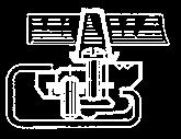
8 Marking control system Semiautomatic resin filling system, with antidrip control Automatic assembly system CH 5453 Busslingen


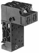
9 Particular realizations Component on manifold mastered Solenoid valves on manifold System for inflating Valves modules on manifold For others configurations, consult us CH 5453 Busslingen

10 General summary Pages Manual actuated valves Position detectors Pressure switches Vacuum Pneumatic logic components Electropneumatic control valves 57 Multifluid solenoid valves Teaching materials CH 5453 Busslingen

11 Manual actuated valves CH 5453 Busslingen


 mm Operating")


12 Push buttons diameter 12 and actuators Features Version Symbol Actuator Valve color color black black NC red black black/red black black grey N0 red grey black/red grey NC Push button round Push button double round NO Characteristics Operating pressure bar Orifice diameter mm Flow at 6 bars Nl/mn. Valves NC : black NO : grey Operating forces (depending on actuator) N Effective travel mm Fluid: dry or lubricated air Pushin connectors for semirigid tubing (NFE 49100) mm Operating temperature C Mechanical life operations Weight g Dimensions Ø x Ø x Threaded barrel 2 threaded barrels CH 5453 Busslingen


13 3position lever manual return position lever spring return Horizontal outputs Vertical outputs Ø x Ø x Ø x Ø x Square lever M3 28,5 CH 5453 Busslingen
 3/2 fixed on")


 use of a round lug.")
14 3/2 valves for manual actuators Ø 22 mm 3/2 valve supplied with screws for fixing the adaptator Valve(s) 3/2 fixed on adaptator (supplied with adaptator not assembled) Adaptator for 3/2 valve on actuators Ø 22 Version Symbol Connection Ø 4 Gas 1/8 Connection Ø NC NO NC NO NC + NO NC + NC Characteristics Operating pressure bar Orifice diameter mm Flow at 4 bars NI/min Control force N Operating temperature in dry air C Life operations Nonconnectable exhaust Weight g x x x x x x Principle of operation Dimensions Ø 22 series NC version Exhaust ,2 1 Supply 2 Output Holes drilled in panel for actuators Ø 22 EN Installation 46,5 32 Holes drilled for the (optional) use of a round lug. * > 40 Ø 40 pushbuttons * > 45 for lever type rotary switches CH 5453 Busslingen
15 Actuators Ø 22 mm for manually operated valves Push buttons 2positions rotary switches 3positions rotary switches Function Red Green Black Flush push contact Emergency stop plastic Ø Emergency stop Ø 40 mm pushturn Black symmetrical actuator Long lever Black Symbol Position Weight g Dimensions Ø Ø 40 13,5 34,5 1 2positions rotary switches 3positions rotary switches Function RONIS key 455 removable in position Black symmetrical actuator Black symmetrical actuator with return Long lever Black Black Long lever, spring to center RONIS key 455 remov. in pos. 0 3 positions with spring to center RONIS key 455 removable in position 0 3 fixed positions Symbol Position 45 2 x 45 2 x 45 2 x 45 2 x 45 2 x 45 2 x 90 Weight Dimensions Ø , Ø 29 27, CH 5453 Busslingen

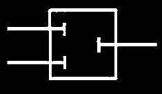
16 Conforms to the Machinery Directive Definition (conforming to EN 574 +A1) A pneumatic 2hand control device is used with dangerous machinery and requires the simultaneous use of both hands to trigger and maintain machine operation. Such a device must be located outside the dangerous zone, so that the operator cannot enter this zone before the machine has come to a complete standstill. A pneumatic 2hand control device is composed of 2 parts : 2 manual pushbuttons which require the simultaneous use of both hands. A pneumatic relay. 1 Types of 2hand control devices Requirements I II Type III A B C Use of both hands (simultaneous actuation) Relationship between input signals and output signal Cessation of the output signal Prevention of accidental operation Prevention of defeat Reinitiation of the output signal Synchronous actuation Use of category 1 (EN 9541) Use of category 3 (EN 9541) Use of category 4 (EN 9541) Category 1 (EN 9541) : the system should use well tried components and principles. Category 3 (EN 9541) : the system must be designed so that a single fault will not cause the loss of the safety function. Category 4 (EN 9541) : the system must be designed so that an accumulation of faults must not lead to a loss of the safety function. Synchronous action An output signal is only generated if both control actuating devices are actuated within 500 ms. Resetting the output signal The release of a single control device interrupts the output signal, but a reset is only possible once both control devices have been released. CH 5453 Busslingen

 81 580 101 81 580 101 81 580 202 2 2 8 2.5 0.2 max.")

17 Pneumatic relay for twohand control 100% pneumatic Complies with Machinery Directive and the standard EN 574 +A1 CE Certification typeiiia and IIIB Part numbers Pneumatic relay for twohand control EN 574 +A1 classification III A III B Symbol Characteristics Operating pressure Orifice diameter Max. delay between input signals Connection Operating temperature Mechanical life Weight bar mm s C operations g max. Subbase Principle of operation Connections (Typical application with doubleacting cylinder) max. Semirigid tubing Ø 4 (NFE 49100) Components follow current standards To obtain an output signal it is necessary to give simultaneous input signals 'a' and 'b' with a max. delay of The output signal 's' is lost if one or both of the inputs are removed. Dimensions , M4 Mounted on subbase (See page 4/15 of Pneumatic catalogue) 32 10,5 125,7 Pb Pa Sb Sa Sb Sb Pb Pb 24 2 x M3 Depth 10 CH 5453 Busslingen
 81 580 504 Type III A 81 580 503 Type III B Symbol")

 5 +50 1.")
18 Twohand pneumatic safety start module Conforms to the Machinery Directive and standard EN 574 Including pneumatic relay to classification IIIA or IIIB depending on version Part numbers Twohand pneumatic safety start module Pneumatic relay (to EN 574) Type III A Type III B Symbol S S 1 P Characteristics Operating pressure Orifice diameter Max. delay between input signals Connection Operating temperature Mechanical life Weight bar mm s C operations g max. Semirigid tubing Ø 4 (NFE 49100) x Connections (Typical application with doubleacting cylinder) P max. Semirigid tubing Ø 4 (NFE 49100) x P S P 1 S Components follow current standards Dimensions Supply via 4 mm pushin fitting Output via 4 mm pushin fitting Fixing viewed from below CH 5453 Busslingen


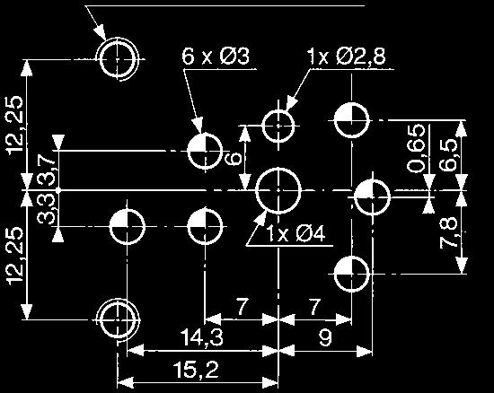
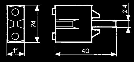
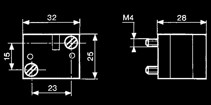
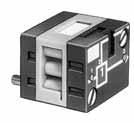
19 Pneumatic impulse counters 4, 5, 6 digits with or without reset With or without preselection Part numbers Totalizer Preselection counter Version Symbol digits no reset to zero digits with manual zero reset digits with manual or pneumatic zero reset Characteristics Supply pressure bar Pressure to break bar Pressure to make bar Reset : Minimum pressure bar Reset time ms Circuit pressure bar Signal emitted when preset is reached Operating temperature C Weight g Connection 2 8 > 0.3 > > 0.3 > > 0.15 > A Output signal P Supply Y 'Reset to zero' signal Z Input signal 1 Note : the count pulse must be removed before the reset pulse is applied. The preset value can be changed during operation without the counter resetting to zero. Dimensions Connectors for semirigid tubing Ø 4 (NFE 49100) ,5 22 x 33,3 5,3 Ø 3.2 f/90 2 holes for M3 screws 24 = = = 0000 Ø 4 Ø 3,2 F/90 = 41,5 = 2 60, = = Ø 4 Ø 3,2 F/90 = 41,5 = 23 = = 37 = 41,5 M3 CH 5453 Busslingen


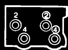
20 Indicators and pedal valves Ergonomics Part numbers Pneumatic indicators Ø 22 Pedal valve Version NC Symbol Red Green Yellow Blue Characteristics Operating pressure Pushin connection for semirigid tubing (NFE 49100) Operating temperature Mechanical life Weight Dimensions bar mm C operations g 8 Ø Ø x White tube Input Output Red tube Holes drilled for indicators CH 5453 Busslingen
21 Position detectors 2 CH 5453 Busslingen


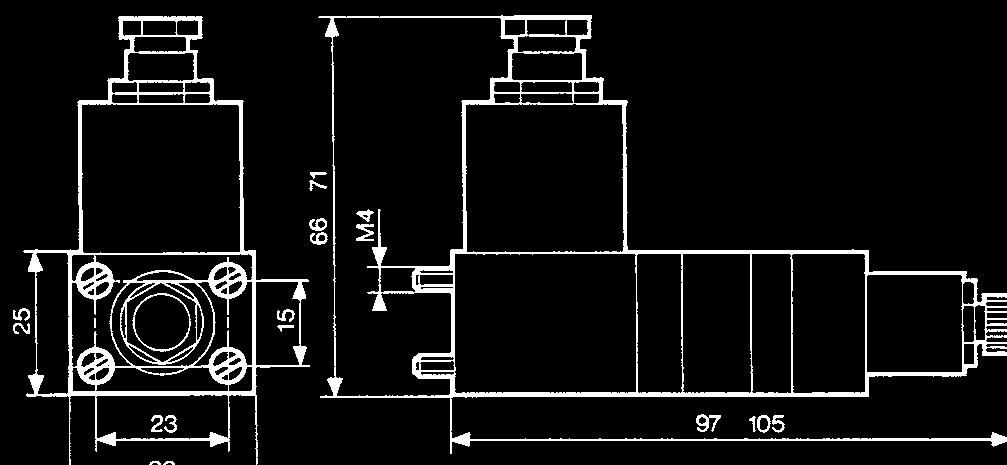
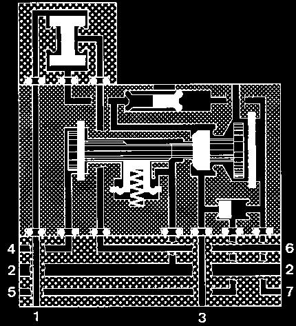
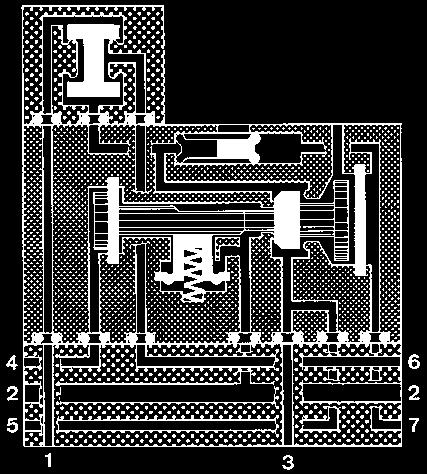
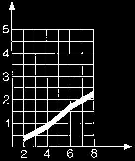
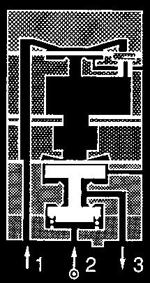
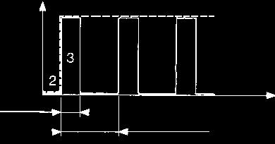
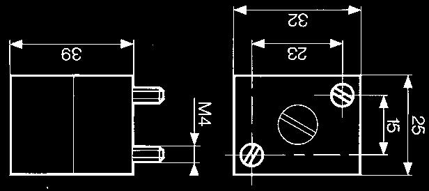
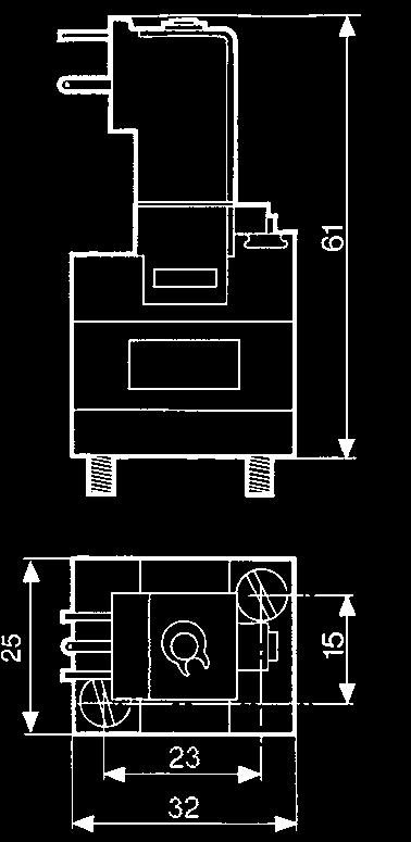
22 Pressure decay sensor 100 % pneumatic Also available in ATEX version for use in potentially explosive atmospheres in accordance with 94/9/EC Directive Pressure decay sensor Symbol Characteristics Operating pressure bar 2 8 Flow at 6 bars NI/min 200 Tripping point with 6 bar supply b 0.3 Connection Subbase page 3637 Operating temperature C Mechanical life operations 10 7 Weight g 25 Connections Without flow restrictor With flow restrictor 2 Signal when cylinder is in Signal when cylinder is out Principle of operation Fitted inline between the cylinder and the control valve, the sensor will give an output when the pressure in this line is exhausted and the cylinder is at end of stroke. For the correct usage of sensors on a falling pressure, it is recommended that the practical cylinder load is limited to 60% of the theoretical force. Evolution of pressure within a doubleacting cylinder Pressure in the cylinder Circuit pressure Working pressure Pressure difference Operation of the sensor on a fall in pressure Exhaust pressure Cylinder response time Control valve changeover Cylinder travel time Starting point End of stroke of cylinder Time Dimensions ATEX version products are available in the following catologues: Pneumatic products for explosive atmospheres or on our website 22 CH 5453 Busslingen


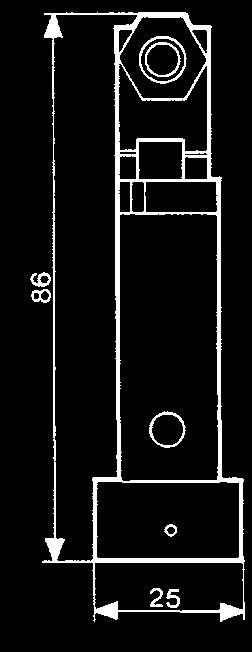
23 Low force position detector 100 % pneumatic Conforme à la nore DIN Forme A Faible effort d'actionnement < 50 g à 6 bars Pas de consommation permanente d'air comprimé Also available in ATEX version for use in potentially explosive atmospheres in accordance with 94/9/EC Directive Function Symbol NO NC Characteristics Orifice diameter mm Operating pressure bar Flow at 4 bars NI/min Activation force at 6 bars N Permissible fluids (air / inert gas) Max/min of fluid C temperatures operating C storage C Mechanical life at 6 bars operation Response on activation ms time on release ms Barb connection for semirigid tubing Weight g Principle of operation NC Desactivated < 0, x < 0, x Activated 2 S (2) (1) Operation accessories Unless otherwise requested, flat and rollerended levers are supplied loose. 161 A flat R E with roller R Dimensions DIN Form A 161 A R 25.4 ±0,2 161 E R 24.1 ±0,2 Ø Total Course travel totale 14.7 ±0.5 Position Tripping d'action point 16 Rest Position point repos ± R R Ø ATEX version products are available in the following catologues: Pneumatic products for explosive atmospheres or on our website 23 CH 5453 Busslingen
24 Microvalve series position detectors 100 % pneumatic Part numbers Version NO NC Features Symbol Horizontal output Vertical output Rear connection by screw NO NC 2 Characteristics Operating pressure bar Orifice diameter mm Flow at 6 bars NI/min Operating force at 6 bars N Effective travel mm Pushin connection for semirigid tubing (NFE 49100) mm Ø 4 Ø 4 Ø 4 Operating temperature C Mechanical life operat. 5 x x x 10 6 Weight g Principle of operation NC NO PFC PA PRT PR Actuation positions : PFC : End of travel position PA : Operating position (max output kv) PRT : Release position (max. exhaust kv) PR : Rest position Dimensions o 5,2 11,5 11,5 CH 5453 Busslingen


25 Microvalve series position detectors 100 % pneumatic Part numbers Features Version NC Vertical output Symbol Short lever With ball Roller trip With roller Threaded barrel Ø 16 Plunger Characteristics Operating pressure bar Orifice diameter mm Flow at 6 bars NI/min Operating force at 6 bars N Effective travel mm Pushin connection for semirigid tubing (NFE 49100) mm Ø 4 Ø 4 Ø 4 Ø 4 Operating temperature C Mechanical life operat. 5 x x x x 10 6 Weight g Dimensions Ø x Ball Ø 9 PR PR PR PR Max. fixing capacity 18 mm 2 nuts 21 mm across flat PR PR Actuation positions : PR : Rest position CH 5453 Busslingen


")
 PRT : Release position (max exhaust kv) PR : Rest position")
26 "Miniature" series position detectors 100 % pneumatic All metal Part numbers Version NC NO Control Symbol Pushin connection for semirigid tubing (NFE 49100) Ø 4 silenced exhaust M5 connectable exhaust Ø 4 connectable exhaust * Ø 6 connectable exhaust * Ø 4 silenced exhaust Ø 6 silenced exhaust Simple plunger Lever with plastic roller Lever with roller bearing NC NC NC Lever with oneway trip plastic roller 2 Operating Characteristics pressure bar Orifice diameter mm Flow at 6 bars NI/min Actuation force at 6 bars N Circuit function : NC Circuit function: NO Connectable exhaust Operating temperature C Mechanical life operations Weight g Principle of operation Actuation travel NC NO Vertical attack Simple plunger Exhaust Actuation positions : Poppet PR = PFC = PA = PO = PRT = PA : Operating position (max output kv) PFC : End of travel position PO : Midposition closed (no exhaust, no outlet) PRT : Release position (max exhaust kv) PR : Rest position Dimensions * with barb for tube Ø 2.7 x 4 Material: body zamak CH 5453 Busslingen


27 Lever with plastic roller Lever with roller bearing Lever with plastic roller Lever with roller bearing NC NC NO Horizontal actuating 30 cam (other angles of attack are also possible, 45 even 90 ). With lever With lever With lever Oneway trip lever PA = PA = PO = PRT = PRT = PO = PA = PO = PRT = PR = ,5 PFC = 25,5 PA = 26 PO = PRT = Horizontal actuating 30 cam (other angles of attack are also possible, 45 even 90 ). PR = PR = 36 Material: body zamak Other configuration on demand CH 5453 Busslingen
 Rotary actuator 81 922 010 Programmable rotary head without lever Rotary")


 PRT : Release position (max exhaust kv) PR : Rest position The detectors 81 922 010 and 81 922 210 can operate to both left")
28 "Compact series position detectors 100 % pneumatic All metal Part numbers Features Version Direct acting Roller plunger with unthreaded barrel Rotary actuator Righthand rotary head with roller lever (CNOMO) Rotary actuator Programmable rotary head without lever Rotary actuator Programmable rotary head without lever Symbol 2 Characteristics BSP Connection pushin for semirigid tubing mm (NFE 49100) Operating pressure bar Bore diameter mm Flow at 6 bars Nm 3 /h Activation force at 6 bars dan Circuit function: NC Mechanical life operations Silenced or connectable (1/8) exhaust Operating temperature C Weight g Accessories Lever with roller plastic bearing Lever with adjustable plastic roller bearing Adjustable steel rod lever Ø > / > Ø > / > Principle of operation Exhaust 2 S Poppet 1 Vertical attack Detectors with roller plunger with unthreaded barrel. Horizontal attack Detectors with roller plunger with unthreaded barrel. PRT PO PA Line of attack Actuation positions : PR PRT PO PA PFC PA : Operating position (max output kv) PFC : End of travel position PO : Midposition closed (no exhaust, no outlet) PRT : Release position (max exhaust kv) PR : Rest position The detectors and can operate to both left and right. Material: body zamak Other configuration on demand CH 5453 Busslingen
29 Rotary actuator Detectors with levers Dimensions ,1 Ø 11 3,4 32,5* 3 Ø 11,6 29,7 23,5 12, ,5 R = ,5* 37 R 120 max ,1 = = Ø 18 36* 25* ,5 CH 5453 Busslingen
 Symbol 81 923 001 Barb for tube 2.")

 mm PFC : End of travel")
 mm mm PR : Rest position mm 0,1 8 2 130 16 1000 5 +50 10 7 27 0,4 0 0,9 1,5 3 0,1 8 2,7 200 21")

 PRT : Release position (max exhaust kv) PR : Rest position")
30 "Adjustable stop" series position detectors 100 % pneumatic All metal Part numbers Pushin connection for semirigid tubing (NFE 49100) Symbol Barb for tube 2.7 x Pushin connector for tube Ø 4 2 Characteristics Operating pressure bar Orifice diameter mm Flow at 6 bars NI/min Actuation force at 6 bars N Circuit function: NC Max. load: without shock dan Will stop a 63 mm Ø cylinder : 6 bar supply Operating temperature C Mechanical life operations Weight g Actuation positions PA : Operating position (max output kv) mm PFC : End of travel position mm PO : Midpoint closed (no exhaust, no outlet) PRT : Release position (max. exhaust kv) mm mm PR : Rest position mm 0, ,4 0 0,9 1,5 3 0,1 8 2, , ,5 3 Principle of operation Exhaust Poppet Black barb Versions PO PA PFC PRT PR With barb Ø Values in mm Actuation positions : PA : Operating position (max output kv) PFC : End of travel position PO : Midposition closed (no exhaust, no outlet) PRT : Release position (max exhaust kv) PR : Rest position Dimensions Fixing This should be as close as possible to the plunger 17 Across flat 17 Across flat M12x1 Material: body zamak CH 5453 Busslingen


 Life at 6 bars operations")


31 Position detectors use with relay 100 % pneumatic All metal Low force operation <N 1 Very low force Version 30 mn References Version Symbole with ball with wire Positive Negative Characteristics Pushin connection for semirigid tubing mm (NFE 49100) Life at 6 bars operations Actuation force at 6 bars N Fluid used: that delivered by the leak sensor relay.. Operating temperature C Weight g Ø , ,5 Ø , , Operating pressure Sensor consumption for relay supply at 6 bar The distance between relay and sensor must be less than 15 m for a tube Ø 2.7 x 4 mm Connection subbase see pages 54/55 Mechanical life Connection bar Nl/ operations Principle of operation Supplied at industrial pressure, the relay produces a permanent bleed at its input port. A sensor shutting off this bleed causes the relay to switch Exhaust Subbase (see page 54/55) Dimensions Connector Ø 4 17 mm Across flat Connector Ø 4 17 mm Across flat Material: brass CH 5453 Busslingen


 Operating temperature C")


32 Position detectors 100 % pneumatic All metal Gap, proximity, paddle Part numbers Detector Symbol de proximité gap gap with palette S P P S 2 Characteristics Detection distance mm 18 mm gap sensor Supply pressure bar Minimum output pressure mbar Unlimited life (static component) Operating temperature C Consumption at supply pressure of: 0.5 b 2.5 b NI/h NI/h Barb connection for semirigid tubing (NFE 49100) mm Operating pressure nozzle sensor d. detection 200 mm bar Flow nozzle at 2 bars sensor at 2 bars at 2 bars at 6 bars Sensor consumption for relay supply at 6 bars Weight Principle of operation d. detection 100 mm bar NI/h NI/h N N NI/min g Ø 2.7 x Ø 2.7 x Ø 2.7 x 4 63 Ø 2.7 x Black barb Black barb 10 max. Connection Supply Used Black barb Black barb Black barb Encombrements Across flat 17 Across flat 17 Across flat CH 5453 Busslingen

 Sensitive amplifiers (for 81 371 401) Version")


 Other information With gap sensors, use an")
33 Ampliers for mounting on installation plan Gap sensor Also available in ATEX version for use in potentially explosive atmospheres in accordance with 94/9/EC Directive Part numbers Simple amplifiers (for /401) Sensitive amplifiers (for ) Version Symbol positive negative positive negative Characteristics Pressure to make mb Operating pressure (nonlubricated air) bar Orifice diameter mm Average consumption at 4 bars Nl/min Permissible overload for 1 hour mb Operating temperature C Mechanical life operations Weight g Connections Used for gaps up to 25 mm. The supply to the sensor should be made via a pressure regulator or oneway flow restrictor (see page 52 Connection subbase x x Black barb x max. Black barb x Principle of operation Simple amplifiers An output at normal industrial pressure is delivered on a low pressure input. NB: Hysteresis is 20% of the pilot pressure. Pilot pressure Supply pressure Pa Positive output Negative output 1 pilot 2 supply 3 output Sensitive amplifiers An output at normal industrial pressure is delivered on a very low pressure input. 5 4 Pilot pressure Note: The specifications are given for a supply pressure of 6 bars, and for detection at the midpoint of the gap. 2 Supply 1 pressure Pa Dimensions Pushin connection for semirigid tubing Ø 4 mm (NFE 49100) Other information With gap sensors, use an amplifier with negative output if you require a signal on interruption of the jet. ATEX version products are available in the following catologues: Pneumatic products for explosive atmospheres or on our website CH 5453 Busslingen


 Min. detectable dimensions Max.")


34 Relais amplificateur semsible avec détendeur intégré Débit réglable Montage rail DIN Part numbers Amplifiers with integral regulator Version Symbol Positive output 2 Characteristics Pressure to make mb Reduced pressure supplied at port 8 bar Flow through port 8 Nm 3 /h Consumption of amplifier only NI/h Permissible overload for 1 hour mb Operating temperature C Mechanical life operations Weight g Detectors (see page 28) Nominal range Min. total consumption for detection (0.5 b regulated pressure) Max. total consumption for short response time (2.5 b regulated pressure) Min. detectable dimensions Max. frequency of use nominal sensing distance 2 Force exerted by the jet on the parts to be detected mm NI/h NI/h mm mm Hz N x Proximity Ø Ø x 10 6 Gap Ø Ø 2 Ø x 10 6 Proximity Ø Ø 7 Ø Connection To use with detectors page 32 Principle of operation pilot pressure This amplifier is suitable for providing a supply to associated sensors. Dimensions Pushin connection for semirigid tubing Ø 4 mm (NFE 49100) Viewed from B Regulated pressure (bar) Viewed from A Adjustable regulator CH 5453 Busslingen
35 CH 5453 Busslingen
36 CH 5453 Busslingen


37 CH 5453 Busslingen
38 CH 5453 Busslingen


39 CH 5453 Busslingen
40 CH 5453 Busslingen

41 CH 5453 Busslingen
42 CH 5453 Busslingen


43 sentronic CH 5453 Busslingen


44 Ω CH 5453 Busslingen

45 sentronic CH 5453 Busslingen


46 CH 5453 Busslingen


47 sentronic CH 5453 Busslingen


48 sentronic CH 5453 Busslingen


49 sentronic CH 5453 Busslingen


50 sentronic CH 5453 Busslingen


51 sentronic CH 5453 Busslingen


52 sentronic CH 5453 Busslingen


53 sentronic CH 5453 Busslingen
54 Ω sentronic CH 5453 Busslingen


55 sentronic CH 5453 Busslingen


56 sentronic CH 5453 Busslingen
57 CH 5453 Busslingen
58 sentronic CH 5453 Busslingen


59 CH 5453 Busslingen


60 CH 5453 Busslingen


61 CH 5453 Busslingen


62 CH 5453 Busslingen


63 CH 5453 Busslingen


64 CH 5453 Busslingen


65 CH 5453 Busslingen
66 Multifluid solenoid valves 6 CH 5453 Busslingen
 Intermediate valve Part numbers Orifice Adjustment diameter KV range Power 0.8 mm 0.")
 Maximum switching rate Weight")
67 Standard 2/2 miniature solenoid valves for fluids and inert gases Autonomous Mounted individually or in a battery Variable orientation coil Low power consumption : 1 W Quick to fit together, no tools needed M5 fittings or possibility of barb Mounting Individual Bank end valves (1 pair) Intermediate valve Part numbers Orifice Adjustment diameter KV range Power 0.8 mm b 1W NC NC NC Standard features Voltage Electrical connections Fluid connection Manual override + pressure indicator 24V c 2.8 x 0.5 blade terminals (W7D5) at 9.4 mm centres tapped holes M5 without 6 General characteristics Response time Operating temperature Viscosity range Vibration resistance Air flow rate (at 2 bars) Maximum switching rate Weight Individual mounting Bank end/inner valves Body material Mechanical life (operations) UL and cul approval MH Accessories for 2/2 miniature solenoid valves Connector for solenoid valve (see page 5/11) Visual indicators 24 V50/60 Hz CC (see page 65) 48 V50/60 Hz AC V50/60 Hz AC V50/60 Hz AC LED seal (see page 65) 1224 V a c Dimensions Individual max 7.5/ blade terminals 2.8 x 0.5 W7D5 3 blade terminals 2.8 x 0.5 W7D tapped holes 45 max x 3.2 mm Ø ( M3 x 18 screw) 18 5 to 15 ms 5 C +50 C up to 30 cst up to 5 g 15 to 40 Nl/mn 30 Hz 32.5 g 35 g Glassreinforced polyamide x 10 7 Bank end valves (1 pair) max / max Intermediate valve = 20 = = 15 = = = = = 30.2 max / max = = = = 15.5 = = 3 blade terminals 2.8 x 0.5 W7D5 1 x 3.2 mm Ø ( M3 x 20 screw) M M CH 5453 Busslingen

68 Standard 3/2 miniature solenoid valves for fluids and inert gases Autonomous Mounted individually or in a battery All connections on one face Small size Mounting Individual Bank end valves (1 pair) Intermediate valve Part numbers Orifice Adjustment diameter KV Débit range Power 0.8 mm b 1W 0.8 mm b 2W 1.2 mm b 2W 1.5 mm b 2W Standard features Voltage Electrical connections Fluid connection Manual override Pressure indicator General characteristics Response time Operating temperature Viscosity range Vibration resistance Air flow rate (at 2 bars) Maximum switching rate Weight Individual mounting Bank end/inner valves Body material Mechanical life (operations) UL and cul approval MH Accessories for 3/2 miniature solenoid valves Connector for solenoid valve (see page 5/11) Visual indicators 24 V50/60 Hz DC (see page 65) 48 V50/60 Hz AC V50/60 Hz AC V50/60 Hz AC LED seal (see page 65) Dimensions Individual NC V a c V c 2.8 x 0.5 blade terminals (W7D5) at 9.4 mm centres tapped holes M5 by impulse without 5 to 15 ms 5 C +50 C up to 30 cst up to 5 g 15 to 40 Nl/min 30 Hz 32.5 g 35 g Glassreinforced polyamide x 10 7 Bank end valves (1 pair) NC Intermediate valve NC blade terminals 2.8 x 0.5 W7D5 Manual override blade terminals 2.8 x 0.5 W7D5 3 blade terminals 2.8 x 0.5 W7D5 Manual override Manual override 26.9 max /8 2 tapped holes max max / max max / max x 3.2 mm Ø ( M3 x 18 screw) x 3.2 mm Ø ( M3 x 20 screw) = 15 = = = M = = = = M = = CH 5453 Busslingen
69 Teaching materials 72 CH 5453 Busslingen
 Characteristics Maintained sequencer subbase assembly 1 relay subbase 1 peripheral subbase 1 plate with 8")

70 Teaching materials Ideal for learning pneumatics For high schools, colleges and training centres Part numbers Training console PUMA 2000 Addon unit Weight (kg) Characteristics Maintained sequencer subbase assembly 1 relay subbase 1 peripheral subbase 1 plate with 8 pushbuttons 1 plate with 8 indicators 1 basic console 1 cylinder mounting plate (3 cylinders + control valves + position detectors) 2 electropneumatic interface units 1 pneumoelectrical interface unit Dimensions CH 5453 Busslingen
71 CH 5453 Busslingen
72 CH 5453 Busslingen
Position detectors.
 Position detectors Pressure decay sensor 00 % pneumatic Also available in ATEX version for use in potentially explosive atmospheres in accordance with 94/9/EC Directive Pressure decay sensor 8 04 0 Operatin
Pneumatics. Switching, automation systems, directional control in industrial and explosive atmospheres. Overview. b Switching.
 Pneumatics Switching, automation systems, directional control in industrial and explosive atmospheres Overview b Switching b Control systems b Directional control Overview Pneumatics Contents b Presentation
For mounting on subbase or footprint in accordance with CNOMO recommendation E 06620N Part numbers (and voltages) Voltage max. power consumption U nom
 Voltage max. power consumption U nom") Intrinsically Safe Miniature Solenoid Valves Order/Technical Support Tel: (800) 6775 / FAX: (800) 677865 / www.crouzetusa.com 5/6 5 For mounting on subbase or footprint in accordance with CNOMO recommendation
Intrinsically Safe Miniature Solenoid Valves Order/Technical Support Tel: (800) 6775 / FAX: (800) 677865 / www.crouzetusa.com 5/6 5 For mounting on subbase or footprint in accordance with CNOMO recommendation
Intrinsically Safe Miniature Solenoid Valves
 Intrinsically Safe Miniature Solenoid Valves 5 Order/Technical Support Tel: (800) 6775 / FAX: (800) 677865 / www.crouzetusa.com 5/6 Intrinsically safe miniature solenoid valves EEx ia T6 approval no. 9
Electro-pneumatic control valves
 Electropneumatic control valves Visit our website for further information www.crouzet.com 9 Electropneumatic miniature solenoid Miniature solenoid valves Terminals Wires Connector LED indicators Valve
MANUALLY AND MECHANICALLY OPERATED VALVES Product Index
 MANUALLY AND MECHANICALLY OPERATED VALVES Product Index Function pipe connections type of operator technology ports/positions * - instant fittings O.D. (mm) w - internal thread ØG * ØG NC NO /8 / /8 Manually
General characteristics Operating fluid Compressed air or inert gas Conditions of use Operating pressure 30 to 20 PSI (2 to 8 bars). Fluid: Filtered a
. Fluid: Filtered a") Pneumatic Logic Components Order/Technical Support Tel: (800) 67753 / FAX: (800) 6773865 / www.crouzetusa.com 5/3 5 General characteristics Operating fluid Compressed air or inert gas Conditions of use
Pneumatic Logic Components Order/Technical Support Tel: (800) 67753 / FAX: (800) 6773865 / www.crouzetusa.com 5/3 5 General characteristics Operating fluid Compressed air or inert gas Conditions of use
Short form catalogue ATEX certified products
 Short form catalogue certified products Products classified for the use in potentially esplosive atmospheres (Directive Atex 94/9/CE) As from the first of July 2003, all products which are commercialised
ATEX LABELLING FOR MOTORS AND GEAR UNITS
 ATEX LABELLING FOR MOTORS AND GEAR UNITS EN ATEX INFORMATION GAS AND DUST COMPLETE DRIVE SOLUTIONS FROM A SINGLE SOURCE RELIABLE n Reliable products n Coordinated components n NORD's own development and
YFC. Limit switch. Ex d. 24 operating head types
 Ex d YFC Limit switch 24 operating head types - Group IIC - Zone 1, 2, 21, 22 - Aluminium alloy - Easy installation, wiring and maintenance - Durable and safe over time Fastening system Earth screw RAL735
Explosion-Protected Pressure Switches
 Explosion-Protected Pressure Switches To new ATEX Standard TECHNICAL DATA 0165 0340 0341 Degree of protection: IP 65 ATEX protection zone: 1 22 22 Switching power: 1 A / 250 VAC 0.25 A / 250 VDC 2 A /
Proportional pressure reducing valves type DHRZO and DHRZA standard and ex-proof version, direct operated, ISO 4401 size 06
 www.atos.com Table TF040-2/E Proportional pressure reducing valves type DHRZO and DHRZA standard and ex-proof version, direct operated, ISO 4401 size 06 A B DHRZO-A-012/25 A B DHRZA-A-010/25 DHRZ* are
T 3965 EN Type 3965 Solenoid Valve Island To control pneumatic actuators
 T 365 EN Type 365 Solenoid Valve Island To control pneumatic actuators Application The Type 365 Solenoid Valve Island is a compact solution for the central control of pneumatic actuators in chemical and
ELECTRO-PNEUMATIC CONTROL VALVES
 WWW.CROUZETCONTROL.COM 7 PNEUMATICS PRODUCTS ELECTROPNEUMATIC CONTROL VALVES WWW.CROUZETCONTROL.COM 8 PNEUMATICS PRODUCTS WWW.CROUZETCONTROL.COM 9 PNEUMATICS PRODUCTS Miniature solenoid valves for alternatin
SPECIAL DUST EXPLOSIVES ATMOSPHERES
 SPECIAL DUST EXPLOSIVES ATMOSPHERES Explosive atmospheres Main sectors of activity subject to a higher risk of explosion or fire Flour mills Wood and aluminium workshops A reference for installations in
nickel-plated brass - PBT technopolymer HNBR, FKM stainless steel
 CATALOGUE > Release 8.7 > Series A solenoid valves Series A directly operated solenoid valves /-way, 3/-way NC and NO. Monostable - bistable (with magnetic memory) Ports M5 - G1/8 - R1/8 - cartridge ø4
USER s MANUAL 1. GENERAL INFORMATION 2. PRODUCT IDENTIFICATION
 1. GENERAL INFORMATION The MICROSOL intrinsic safety solenoid valves produced by Fluid Automation Systems SA are dedicated to piloting fluids in explosive atmospheres according to the ATEX 94/9/CE directive,
MICRO SOLENOID VALVE pinch mechanism for flexible tube O.D to 9.5 mm
 MICRO SOLENOID VALVE pinch mechanism for flexible tube O.D..65 to 9.5 mm U / Series 84 FEATURES Solenoid valve suitable for cutting off the flow of a fluid by pinch For sterile, aseptic, physiological
Versions. Version with K VS Version with K VS 2.0. Fig. 1: Type 3967 Solenoid Valve
 Type 367 Solenoid Valve Application Solenoid valve for controlling pneumatic linear actuators with NAMUR rib according to IEC 60534 or pneumatic rotary actuators with NAMUR interface according to VDI/VDE
INDUSTRY PROCESS AND AUTOMATION SOLUTIONS. Technical Bulletin
 INDUSTRY PROCESS AND AUTOMATION SOLUTIONS Technical Bulletin Guidelines for selection of planetary gear units of the 300- INDUSTRIAL series for installation in hazardous areas, classified by Directive
Lenze ATEX-compliant gearboxes Gearboxes for use in potentially explosive atmospheres
 Lenze ATEX-compliant gearboxes Gearboxes for use in potentially explosive atmospheres ATEX for drive technology The ATEX directive, which has been in force since July 1, 2003, has been introduced in an
Table of contents. Technical informations > ATEX Page Technical informations Page Mechanically operated valves Page 13-06
 Technical informations > Table of contents ATEX Page 13-02 Technical General informations information Page 13-02 Mechanically operated valves Page 13-06 Pneumatically operated valves Page 13-06 Electrically
Series 3730 Electropneumatic Positioner Type
 Series 3730 Electropneumatic Positioner Type 3730-1 Application Single-acting or double-acting positioner for attachment to pneumatic control valves. Self-calibrating, automatic adaptation to valve and
DIRECT OPERATED SOLENOID PILOT VALVES Product Index
 DIRECT OPERATED SOLENOID PILOT VALVES Product Index ports/positions Function pipe connections * - instant fittings O.D. (mm) w - internal thread (ØG) x - external thread (ØG) n - pad mount : - pad mount,
Explosion-proof Solenoids ATEX. II 2 G / II 2 D EEx dm IIC T4, T5, T6. Catalogue 8735/GB. Maximum photo
 Explosion-proof Solenoids II 2 G / II 2 D EEx dm IIC T4, T5, T6 Catalogue Maximum photo ATEX Explosionproof solenoids with flameproof enclosure/encapsulation "dm" According to ATEX directive 94/9/EC and
Input, Control and Processing elements
 PNEUMATIC & HYDRAULIC SYSTEMS CHAPTER FIVE Input, Control and Processing elements Dr. Ibrahim Naimi Valves The function of valves is to control the fluid path or the pressure or the flow rate. Depending
Intrinsically safe solenoid valves on/off controls - ATEX or IECEX certification
 Table E3-/E Intrinsically safe solenoid valves on/off controls - ATEX or IECEX certification valve body valve spool intrinsically safe solenoid electrical connector manual override DHW-6/WP/6 On/off valves
Electropneumatic Converters i/p Converters Type 6111 Mounting and Operating Instructions EB 6111 EN
 Electropneumatic Converters i/p Converters Type 6111 Fig. 1 Type 6111 in standard version Fig. Type 6111 mounted on a supply air manifold Fig. 3 Type 6111 in field enclosure Mounting and Operating Instructions
Chapter 11: Valves and Actuators with the NAMUR-interface
 Right of authorship: the content of the training (wording, drawings, pictures) are owned by the author. Any utilization except for individual use is allowed only after permission of the author. Valves
nickel-plated brass - PBT technopolymer HNBR, FKM stainless steel
 CATALOGUE > Release 8.8 > Series A solenoid valves Series A directly operated solenoid valves /-way - Normally Closed (NC) and Normally Open (NO) 3/-way - Normally Closed (NC) and Normally Open (NO)»»
TX³ RCCBs 2P up to 100 A
 87045 LIMOGES Cedex Telephone number: +33 (0)5 55 06 87 87 Fax: +33 (0)5 55 06 88 88 TX³ RCCBs CONTENTS PAGE 1. Description, use... 1 2. Range... 1 3. Overall dimensions... 1 4. Preparation - Connection...
Control block VOFA with safety function
 Key features Innovative Versatile Reliable Easy to assemble Can be used for safe reversing of a hazardous movement (5/2-way solenoid valve) Can be used for safe venting (3/2-way solenoid valve function,
15 mm Pilot Valve. More technical specifications are reported in the following pages. 1
 15 mm Pilot Valve The 15 mm pilot valve has been designed and developped by Amisco as a logical evolution of the traditional product range manufactured for the pneumatic market. The 15 mm solenoid valve
3/2-, 5/2- and 5/3-way Solenoid Valves for process pneumatics
 /-, 5/- 5/-way Solenoid Valves for process pneumatics Type 658 stard High flow-rate capacity Reduced power consumption Single or manifold mounting stard Type 658/659 can be combined with... Stard-, EEx
p max (see table of performances) Q max (see table of performances) bar Maximum flow l/min see par
 Q max (see table of performances) bar Maximum flow l/min see par") 41 510/112 ED EXPLOSION-PROOF VERSION SOLENOID OPERATED DIRECTIONAL CONTROL VALVES in compliance with ATEX 94/9/EC MD1K ISO 4401-03 (CETOP 03) E4P4K CETOP P05 E07P4K ISO 4401-07 (CETOP 07) E5P4K ISO 4401-08
41 510/112 ED EXPLOSION-PROOF VERSION SOLENOID OPERATED DIRECTIONAL CONTROL VALVES in compliance with ATEX 94/9/EC MD1K ISO 4401-03 (CETOP 03) E4P4K CETOP P05 E07P4K ISO 4401-07 (CETOP 07) E5P4K ISO 4401-08
Shut-off dampers. Type AK-Ex. For low-leakage shut-off of volume flows in potentially. explosive atmospheres (ATEX) PD AK-Ex 1.
 PD AK-Ex 1.") X X testregistrierung Shut-off dampers Type ATEX-compliant parts and units For low-leakage shut-off of volume flows in potentially explosive atmospheres (ATEX) Circular shut-off dampers for shutting off
X X testregistrierung Shut-off dampers Type ATEX-compliant parts and units For low-leakage shut-off of volume flows in potentially explosive atmospheres (ATEX) Circular shut-off dampers for shutting off
Offshore and Onshore Applications Lucifer TM 2/2 and 3/2 ways 316L Stainless Steel solenoid valves
 aerospace climate control electromechanical filtration fluid & gas handling hydraulics pneumatics process control sealing & shielding courtesy of Statoil Offshore and Onshore Applications Lucifer TM 2/2
Subject: Pneumatic Training Kit with portable Air Compressor
 MSME TOOL ROOM: HYDERABAD (CENTRAL INSTITUTE OF TOOL DESIGN) Balanagar, Hyderabad 500 037 TEL.NO.23772747, 23776168 FAX No.0-4023772658 E-mail:citdpurchase@citdindia.org Visit us: www.citdindia.org. TENDER
3/2 Way Valve G1/8. Data Sheet No E. Characteristics Symbol Unit Description General Features Spool valve.
 AP64E00DX00X Characteristics to VDI 90 Pressures quoted as gauge pressure Characteristics Symbol Unit Description General Features Spool valve Mounting screws M Tube connection Thread Port size ; 7.4 deep
Kuhnke Technical Data. Contact Details
 Kuhnke Technical Data The following page(s) are extracted from multi-page Kuhnke product catalogues or CDROMs and any page number shown is relevant to the original document. The PDF sheets here may have
Ex m Solenoid Operator Type 0519
 nass magnet GmbH Eckenerstrasse 4-6 D-30179 Hannover Doc. No. 113-720-0002 Revision No. 2 01.06.2015 Ex m Solenoid Operator Type 0519 Operating Instructions Dear Customer! To ensure the function and for
Attachments. Explosion-proof actuators. For opening and closing multileaf dampers installed in potentially explosive atmospheres (ATEX) 09/2017 DE/en
 09/2017 DE/en") X X testregistrierung Attachments Limit switch Solenoid valve Pneumatic actuator Electric actuator For opening and closing multileaf dampers installed in potentially explosive atmospheres (ATEX) for Type
X X testregistrierung Attachments Limit switch Solenoid valve Pneumatic actuator Electric actuator For opening and closing multileaf dampers installed in potentially explosive atmospheres (ATEX) for Type
Type 4746 Electric or Pneumatic Limit Switch
 Type 4746 Electric or Pneumatic Limit Switch Application Limit switches with inductive, electric or pneumatic contacts for attachment to pneumatic or electric control valves, to Type 4763 Electropneumatic
XCKJ390559H29EX limit switch XCKJ - round rod Ø 6 mm - 2NC + NO - ATEX/IECEx
 Characteristics limit switch XCKJ - round rod Ø 6 mm - 2NC + NO - ATEX/IECEx Main Range of product OsiSense ATEX D Series name Standard format Product or component type Limit switch Device short name XCKJ
Type 2511/12. Type Type 2030 Cable plug. ASI cable plug. Dosing control. General technical data Orifice Type 6518
 3/2-, 5/2- and 5/3-way Solenoid Valves for process pneumatics Type 658 standard standard High flow-rate capacity Reduced power consumption Single or manifold mounting Standard-, EEx m and EEx i versions
2/2 Solenoid Cartridge Valve, Size 6
 / Solenoid Cartridge Valve, Size 6 Q max = l/min (.3 gpm), p max = 3 bar (4 psi) Bidirectional leak-proof shutoff, direct acting, with EX-safty solenoid coil Description Valve: Bidirectional leak-proof
Technical Data. Dimensions
 Model Number Features 40 mm flush 4-wire DC ATEX-approval for zone 2 and zone 22 S Technical Data specifications Switching element function PNP NO/NC Rated operating distance s n 40 mm Installation flush
DX³ RCCBs - ID 4P up to 100 A
 87045 LIMOGES Cedex Telephone number: +33 (0)5 55 06 87 87 Fax: +33 (0)5 55 06 88 88 DX³ s - ID CONTENTS PAGE 1. Description, use... 1 2. Range... 1 3. Overall dimensions... 1 4. Preparation - Connection...
Quickstepper FSS Key features
 Key features Description Pneumatic/mechanical sequencer with 12 steps and start logic circuits Ready-to-install sequence controller Acknowledgement-controlled motion sequences The Quickstepper is a mini
INLINE Flow sensor for hazardous area II 1 G/D - II 2 D - II 3 GD - I M1
 INLINE Flow sensor for hazardous area II G/D - II D - II GD - I M Type SE0 Ex can be combined with... Flow meter with NAMUR or NPN/PNP output signal Mounting, dismounting of electronics by a Quarter-Turn
3/2-, 5/2- and 5/3-way Solenoid Valves for process pneumatics
 /2-, 5/2-5/-way Solenoid Valves for process pneumatics Type 658 stard High flow-rate capacity Reduced power consumption Single or manifold mounting stard Type 658/659 can be combined with... Stard-, EEx
Body: Seat disc: Anod. aluminium body NBR. Connection / Orifice Flow factors Temperature values ( C)
") Parker Lucifer Data Sheet 22062004 General information Lucifer ref.: 341N31 Global ref.: 7341NAKBJNM0 Housing ref.: 2995 Coil ref.: 481865 Protection class: Assembly wt. (g): 510 Body: Seat disc: Anod.
Parker Lucifer Data Sheet 22062004 General information Lucifer ref.: 341N31 Global ref.: 7341NAKBJNM0 Housing ref.: 2995 Coil ref.: 481865 Protection class: Assembly wt. (g): 510 Body: Seat disc: Anod.
Modern Explosion Protection
 Industrial Hydraulics Electric Drives and Controls Linear Motion and Assembly Technologies Pneumatics Service Automation Mobile Hydraulics Modern Explosion Protection ATEX valves for use in industrial
Pneumatic Power Valves Series 75/76 Manual, Mechanical, Pneumatic and Electric Valves
 Quic-Pics Catalogue Pneumatic Power Valves Series 75/76 Manual, Mechanical, Pneumatic and Electric Valves Contents: Product Line Overviews 2 Manually Operated Valves 5 Pushbuttons 6 Toggle Switch 8 Knob
Sentronic PLUS 614 Series
 Sentronic PLUS 64 Series Proportional Technology www.asco.com PRESSURE CONTROL: 64 SERIES SENTRONIC PLUS Sentronic PLUS Sentronic PLUS is a digitally operated pressure regulator valve. This valve accurately
Flameproof Enclosures
 Flameproof Enclosures The range comprises many standard sizes of enclosures manufactured in stainless steel 316L and/or in painted carbon steel. The enclosures allow for utilization of standard electrical
Solenoid coils VACF Type codes
 Solenoid coils VACF Type codes VACF B B2 1A Type VACF Solenoid coil, F series Solenoid coil type A B Width 30 mm, for 8 mm armature tube Width 22 mm, for 8 mm armature tube A1 Connection pattern type A,
Direct-acting 3/2 way plunger valve
 Direct-acting 3/2 way plunger valve Direct-acting, compact valve with diameter of up to DN 2.5 Vibration-proof, bolted coil system Banjo threaded connection for direct mounting on pneumatic valves Type
-V- New. Valve series VOFC. 2009/08 Subject to change Internet:
 Valve series VOFC 2009/08 Subject to change Internet: www.festo.com/catalogue/... 159 Solenoid valves VOFC Key features General information The valves in the VOFC series are special 3/2-way and 5/2-way
System 6000 Electropneumatic Converter for Direct Current Signals Type 6116 i/p Converter
 System 6000 Electropneumatic Converter for Direct Current Signals Type 6116 i/p Converter Application Used to convert a direct-current input signal into a pneumatic output signal for measuring and control
VD4 Installation and service instructions kv A ka
 Medium voltage products VD4 Installation and service instructions 12... 36 kv - 630... 3150 A - 16... 50 ka Index For your safety! 1 I. Introduction 2 II. Programme for environmental protection 2 1. Packing
MINI-SOLENOID VALVES ISO (CNOMO, size 15) interface direct operated, pad mounting body connector size 15
 interface direct operated, pad mounting body connector size 15") MINI-SOLENOID VALVES ISO 58 (CNOMO, size 5) interface direct operated, pad mounting body connector size 5 NC / Series 0 FEATURES Compact, monobloc solenoid pilot valve with spade-plug connector type EN
MINI-SOLENOID VALVES ISO 58 (CNOMO, size 5) interface direct operated, pad mounting body connector size 5 NC / Series 0 FEATURES Compact, monobloc solenoid pilot valve with spade-plug connector type EN
Series PD directly operated solenoid valves
 > Series PD solenoid valves CATALOGUE > Release 8.8 Series PD directly operated solenoid valves /-way - Normally Closed (NC) Please note that all Series PD solenoid valves are supplied with direct current
[You may download this article at: https://fluidsys.org/downloads/ ]
![[You may download this article at: https://fluidsys.org/downloads/ ]](/thumbs/75/72588514.jpg "[You may download this article at: https://fluidsys.org/downloads/ ]") Fluidsys Training Centre, Bangalore offers an extensive range of skill-based and industry-relevant courses in the field of Pneumatics and Hydraulics. For more details, please visit the website: https://fluidsys.org
Fluidsys Training Centre, Bangalore offers an extensive range of skill-based and industry-relevant courses in the field of Pneumatics and Hydraulics. For more details, please visit the website: https://fluidsys.org
P r e s s u r e i S w i t c h e s V a c u u m i S w i t c h e s PressureiTransmitters
 P r e s s u r e i M o n i t o r i n g P r e s s u r e i S w i t c h e s V a c u u m i S w i t c h e s PressureiTransmitters TRADITION AND INNOVATION From a mechanical workshop to an international industrial
System Electropneumatic Converters (Proportional Valves) Electronic Process Controllers Signal Converters
 Electronic Process Controllers Signal Converters") System 6000 Electropneumatic Converters (Proportional Valves) Electronic Process Controllers Signal Converters Edition April 2018 Information Sheet T 6000 EN Electropneumatic Converters i/p converters
System 6000 Electropneumatic Converters (Proportional Valves) Electronic Process Controllers Signal Converters Edition April 2018 Information Sheet T 6000 EN Electropneumatic Converters i/p converters
Sensor boxes SRBE Key features and product range overview
 Sensor boxes SRBE Sensor boxes SRBE Key features and product range overview Function Sensor boxes SRBE are used for electrical feedback and control of the position of process valves actuated using pneumatic
UNI EN ISO EN
 Airplus Safeline eneral Upon implementation of the AIRPLUS T series, air-treatment units, PNEUMAX develops a supply and discharge valve, with an electropneumatic control and spring-return, fitted with
Solenoid valves VMPA
 Key features Innovative Versatile Reliable Easy to mount Slim high-performance valves in a sturdy metal housing MPA1 (width 10 mm): flow rate up to 360 l/min MPA14 (width 14 mm): flow rate up to 670 l/min
Type Electronic Limit Switch
 Type 3738-20 Electronic Limit Switch With optional solenoid valve Application Electronic limit switch for on/off applications to indicate the end position. Optionally with integrated solenoid valve. Special
Series PD directly operated solenoid valves
 > Series PD solenoid valves CATALOGUE > Release 8.7 Series PD directly operated solenoid valves New /-way Normally Closed (NC) Note: all Series PD /-way solenoid valves are basically in DC. To operate
Valves and Solenoid valves Series E 2/
 CATALOGUE > Release 8.6 > Series E valves and solenoid valves Valves and Solenoid valves Series E 5/-way monostable/bistable - 5/3 CC CO CP With outlets on the body - For individual or manifold assembly
Common wiring modules can be connected by fieldbus, multi-pole or common earth/neutral modules.
 / and 4/ multi-way valves; servo assisted; DN 4; flow rate: l/min.; /8, legris ø 6 mm port connections Advantages / Benefits Optimised system solutions due to high level of modularity Compact design with
SPOOL VALVES solenoid air operated 1/4 to 1/2 tapped body and NAMUR for integrated pilot
 SPOOL VALVES operated / to / tapped body and NAMUR for integrated pilot ATEX /-/ Series - FEATURES The valves offer environmental protection against the ingress of liquids, dusts or other foreign matter
CPC DX (CPC Dual Transfer Skid) Redundant current to pressure converter assembly
 Redundant current to pressure converter assembly") Product Specification 03421 (Revision NEW, 5/2015) CPC DX (CPC Dual Transfer Skid) Redundant current to pressure converter assembly Applications The CPC-DX (current-to-pressure converter dual transfer)
Product Specification 03421 (Revision NEW, 5/2015) CPC DX (CPC Dual Transfer Skid) Redundant current to pressure converter assembly Applications The CPC-DX (current-to-pressure converter dual transfer)
Type AK-Ex FOR LOW-LEAKAGE SHUT-OFF OF VOLUME FLOWS IN POTENTIALLY EXPLOSIVE ATMOSPHERES (ATEX)
") Homepage > Products > Control units > Shut-off and restriction > Shut-Off Devices > Type AK-Ex Type AK-Ex FOR LOW-LEAKAGE SHUT-OFF OF VOLUME FLOWS IN POTENTIALLY EXPLOSIVE ATMOSPHERES (ATEX) Circular shut-off
Homepage > Products > Control units > Shut-off and restriction > Shut-Off Devices > Type AK-Ex Type AK-Ex FOR LOW-LEAKAGE SHUT-OFF OF VOLUME FLOWS IN POTENTIALLY EXPLOSIVE ATMOSPHERES (ATEX) Circular shut-off
Explosion protection. Air + combustible gas + ignition source = explosion. Air + combustible dust + ignition source = explosion
 Ex-protection Explosion protection Valves for fluid technology for use in explosion hazard areas Explosion protection for gas, dust and mining Flameproof enclosures and intrinsic safety Solutions for all
Standard valves to ISO Product range overview
 Standard valves to ISO 15218 Product range overview Function Electrical connection Voltage Manual override Page/Internet Pilot valve to ISO 15218 Width 15 mm Plug connector type C, to EN 175301-803 Plug
2/ VDMA (ISO ) 5/2-5/3-way CC CO CP. CATALOGUE > Release 8.8 CONTROL > Series 7 valves and solenoid valves GENERAL DATA
 5/2-5/3-way CC CO CP. CATALOGUE > Release 8.8 CONTROL > Series 7 valves and solenoid valves GENERAL DATA") CATALOGUE > Release 8.8 > Series 7 valves and solenoid valves Series 7 valves and solenoid valves VDMA 4563 (ISO 15407-1) 5/ - 5/3-way CC CO CP Size 6 mm (VDMA 4563-01) Size 18 mm (VDMA 4563-0) GENERAL
CATALOGUE > Release 8.8 > Series 7 valves and solenoid valves Series 7 valves and solenoid valves VDMA 4563 (ISO 15407-1) 5/ - 5/3-way CC CO CP Size 6 mm (VDMA 4563-01) Size 18 mm (VDMA 4563-0) GENERAL
Masoneilan. Model 8007 and 8008 Electropneumatic Transducers. New Nozzle Design Minimises Effect of Vibration. Specification Data BS 6500 E 06/03
 Masoneilan Model 8007 and 8008 Electropneumatic Transducers Specification Data BS 6500 E 06/03 New Nozzle Design Minimises Effect of Vibration New Nozzle Design Minimises Effect of Vibration Model 8007
Type 3761 Pneumatic or Electropneumatic Positioner for Rotary Actuators. Fig. 1 Type 3761 Positioner. Mounting and Operating Instructions EB 8386 EN
 Type 3761 Pneumatic or Electropneumatic Positioner for Rotary Actuators Fig. 1 Type 3761 Positioner Mounting and Operating Instructions EB 8386 EN Edition July 2007 Contents Contents Page 1 Design and
2/2-way, 3/2-way NC and NO. Monostable - bistable (with magnetic memory) Ports M5 and G1/8 - cartridge ø4
 Ports M5 and G1/8 - cartridge ø4") CATALOGUE > Release 8.5 > Directly operated solenoid valves Series A Directly operated solenoid valves Series A /-way, 3/-way NC and NO. Monostable - bistable (with magnetic memory) Ports M5 and G1/8 -
CATALOGUE > Release 8.5 > Directly operated solenoid valves Series A Directly operated solenoid valves Series A /-way, 3/-way NC and NO. Monostable - bistable (with magnetic memory) Ports M5 and G1/8 -
Type 6213 EV, 6281 EV
 Type 6213 EV, 6281 EV 2/2-way solenoid valve 2/2-Wege-Magnetventil Électrovanne 2/2 voies Operating Instructions Bedienungsanleitung Manuel d utilisation 1 OPERATING INSTRUCTIONS The operating instructions
Technical Documentation
 Technical Documentation Product manual Holding brake controller Document: 0198441113316 Edition: V1.00, 03.2006 Important information The drive systems described here are products for general use that
Test. What type of cylinder would you use? A. Single-acting cylinder B. Double-acting cylinder Answer:
 Test This test allows you to establish whether your basic knowledge of pneumatic controls is sufficient for you to attend the advanced course P or whether you should attend the basic level course P. The
Electronic Limit Switch Type
 Electronic Limit Switch Type 3738-20 with optional solenoid valve for on/off rotary actuators Application Electronic limit switch for on/off applications to indicate the end position of rotary actuators.
DHAXW4-07*/M DHOXW-06* Input Power. 32 W (only for 12 and 24 DC) 40 W (only for 110 and 220 DC) 8 W 25 W T6 T4 8 W 25 W T4 T3 T6 T4 T4 T3 25 W 8 W
 40 W (only for 110 and 220 DC) 8 W 25 W T6 T4 8 W 25 W T4 T3 T6 T4 T4 T3 25 W 8 W") www.atos.com Table TE137obs/E Stainless steel valves for water base fluids standard or ex-proof solenoid valves with Multicertification TEX, IECEx, EC or CULUS certification UL certified valves are obsolete
www.atos.com Table TE137obs/E Stainless steel valves for water base fluids standard or ex-proof solenoid valves with Multicertification TEX, IECEx, EC or CULUS certification UL certified valves are obsolete
Direct-acting 2/2-way plunger valve
 Direct-acting 2/2-way plunger valve Type can be combined with Direct-acting and compact valve up to diameter of DN 6.0 Vibration-proof, bolted coil system Increased leak-tightness with welded plunger guiding
P r e s s u r e i S w i t c h e s V a c u u m i S w i t c h e s PressureiTransmitters
 P r e s s u r e i M o n i t o r i n g P r e s s u r e i S w i t c h e s V a c u u m i S w i t c h e s PressureiTransmitters TRADITION AND INNOVATION From a mechanical workshop to an international industrial
Solenoid valves MHJ, fast-switching valves
 Solenoid valves MHJ, fast-switching valves Solenoid valves MHJ, fast-switching valves Key features Innovative Versatile Reliable Easy to install Individual electrical connection via connecting cable and
ADVANTAGES. Air + combustible gas + ignition source = explosion. Air + combustible dust + ignition source = explosion
 EX-PROTECTION ADVANTAGES Valves for fluid technology for use in explosion hazard areas Explosion protection for gas, dust and mining Flameproof enclosures and intrinsic safety Solutions for all zones The
TRESHOLD SENSORS LOGIC PNEUMATIC COUNTERS TIMERS VALVES
 PNEUMATIC TIMERS N.C / N.O. PNEUMATIC COUNTERS with / VALVE PANEL MOUNTED PNEUMATIC COUNTERS LOJIC VALVES OR GATES TRESHOLD SENSORS LOGIC PNEUMATIC COUNTERS TIMERS VALVES LOGIC PNEUMATIC LOGIC VALVES
RVP-R- VAV controller. In explosion-proof version
 VAV controller In explosion-proof version RVP-R- SMAY LLC / 29 Ciep³ownicza St. / 31-587 Cracow / Poland tel. +48 12 378 18 00 / fax. +48 12 378 18 88 / e-mail: info@smay.eu Intended use VAV control units
: Automation Laboratory 1
 Table A.1 shows elements found in FluidSIM library with a brief description for each of them. Compressed air supply The compressed air supply provides the needed compressed air. It contains a pressure
Series
 PNEUMATI valves Series 79-8 - 84-85 - 87 Steelspool Valves Solenoid Valves Mechanical Valves Pneumatic Valves oils & Plug-in sockets VM/EN 4 The components illustrated and described in the present calalogue
Explosion protected hydraulic products. Product overview industrial and mobile hydraulics
 Explosion protected hydraulic products Product overview industrial and mobile hydraulics 2 Explosion protected hydraulic products Recognizing hazards and categorizing them correctly Legal directives such
Solenoid System. The coil is also in conformity with 94/9/EC ATEX for electrical apparatus of group II, category 3 (Ex na II 3 GD T4 or T5).
.") EVI 7 S9 Solenoid System The EVI7 S9 system by AMISCO includes a wide range of solenoids, coils and operators, designed for pneumatic valves. All solenoids of this system have the guide tube with a diameter
EVI 7 S9 Solenoid System The EVI7 S9 system by AMISCO includes a wide range of solenoids, coils and operators, designed for pneumatic valves. All solenoids of this system have the guide tube with a diameter
MINIATURE MICROSWITCHES - STANDARD
 0/08 MINIATURE MICROSWITCHES - STANDARD VD - 8 C-spring snap-action mechanism with wiping contacts Ratings from 0.0 A Vc up to A 0 Va and hp Va / hp 0 Va Broad range of operating forces from 0. N to N
PTEX extruder pumps Pneumatic extruder pump for drums of grease up to NLGI grade 2
 1-4009-EN PTEX extruder pumps Pneumatic extruder pump for drums of grease up to NLGI grade 2 The PTEX extruder pumps are pneumatically actuated pumps designed to deliver lubricant under pressure to lubrication
DNX 3 MCB 4500 A / 6 ka Phase + Neutral, neutral on left side
 87045 LIMOGES Cedex Telephone number: +33 (0)5 55 06 87 87 Fax: +33 (0)5 55 06 88 88 DNX 3 MCB 4500 A / 6 ka CONTENTS PAGE 1. Description, use... 1 2. Range... 1 3. Overall dimensions... 1 4. Preparation