SCOTCH YOKE PART TURN PNEUMATIC ACTUATOR DAN 15 - DAN 1920 / SRN 15 - SRN 960
|
|
|
- Imogen Gregory
- 5 years ago
- Views:
Transcription


1 INSTRUCTION MANUAL - 1
2 INX: Pag. 1. GERAL FEATUR 3 2. WORKING CONDIONS 3 3. OPERATION AND ROTATION DIRECTION 6 4. SAFETY INFORMATION 8 5. INSTALLATION INSTRUCTION 9 6. MATERIALS AND THEIR DURABILY MAINTANCE SPECIAL VERSIONS STORAGE TROUBLHOOTING DISPOSAL OF PRODUCTS AT THE D OF THEIR LIFE CYCLE CLARATION OF CONFORMY 25 Environmentally friendly: under the green leaf icon you can find the instructions for a correct and environmentally friendly handling of the product. reserves the right to change, at any time, the features and data of its own products, to better improve the quality and the duration of said products. FOREWORD The present User s Installation and Maintenance Manual has been edited in conformity with: 2006/42/EC Directive Machinery ; 2014/34/UE Directive Equipment and protection systems designated to be used in potentially explosive atmospheres (ATEX). The following standards/technical specifications also apply: :2009 Industrial valves: Actuators Pneumatic part-turn actuators for industrial valves. IEC 61508:2010-1/7 Functional safety of electrical/electronic/programmable electronic safety-related systems. Part 1 :7 UNI C/TS 764-6:2005 Pressure equipment Part 6: Operating instructions structure and contents. Below you will find the safety instructions, the minimum information for storage / warehousing, the installation, the commissioning, the main-tenance and the instructions for disposal of products at the end of their life cycle for the pneumatic actuators: Where provided, the actuators are CE marked in accordance with the applicable European Directives (ex. 2014/34/UE - ATEX). OMAL disclaims any liability for damage caused by improper use, even if partial, respect to the information contained in this manual. - 2
3 1. GERAL FEATUR OMAL manufacture a wide range of part turn pneumatic actuators for valve remote control. The actuators are available on Double Acting DA and Spring Return SR versions. - The principle of the actuator application is to open and close the connected valve, without the manual operation with lever or hand wheel, by means of an electric-pneumatic connection on remote control. - Scotch Yoke is a mechanical system that allows to transform the linear force into a rotary torque. OMAL applies the scotch - yoke system for its actuator production to transfer the pistons linear force to a driving shaft torque. This system provides a long working life and best performance with the minimum energy consumption. - OMAL Scotch-Yoke system with its oblique grooves produces a torque curve with the highest torque at the start opening operation in order to overcome the valve breakaway torque. The maintenance should be done by OMAL trained personnel only. This instruction manual contains important information regarding the OMAL Scotch-Yoke pneumatic actuator operation, installation, maintenance and storage. Please read carefully before installation and keep it in a safe place for further reference. 2. WORKING CONDIONS a. Construction Standard OMAL actuators are suitable for indoor and outdoor installation. The laser marking or a printed label on the actuator body gives the actuator technical characteristics: type, size, operating pressure, output torque, operating temperature, flange connection, product code and production date. b. Motive energy The operating media should be dry and filtered compressed air not necessarily lubricated or inert gases compatible with internal actuator parts and lubricants. The operating medium shall have a dew point equal to 20 C or, to be at least, 10 C below the ambient temperature ( ISO , Class 3 ). The maximum particle size shall not exceed 40 μm ( ISO , Class 5 ). c. Supply operating media pressure The maximum supply pressure is 8,4 bar ( 120 psi ) Nominal supply pressure is 5,6 bar ( 80 psi ), working pressure range from 2,5 bar ( 36 psi ) up to 8,4 bar (120 psi ). d. Operating temperature Actuator standard working temperature range form 20 C ( -4 F ) to 80 C ( 176 F ) For low and high temperature versions please contact OMAL. For high humidity and low temperature application are recommended to use a supplementary protection ( e.g. screens, sheds or integral painting) e. Operating drive rotation The part turn actuator rotation angle is nominally 90. OMAL actuator provides a stroke of 92 rotation, from 1 to 91, with standard stroke adjustment of 10. f. Cycle time The cycle time is dependent on different operating and installation factors such as the supply pressure, the flow capacity, the connection pipe size, the solenoid valve performance, the valve torque and characteristics, environmental temperature condition. - 3
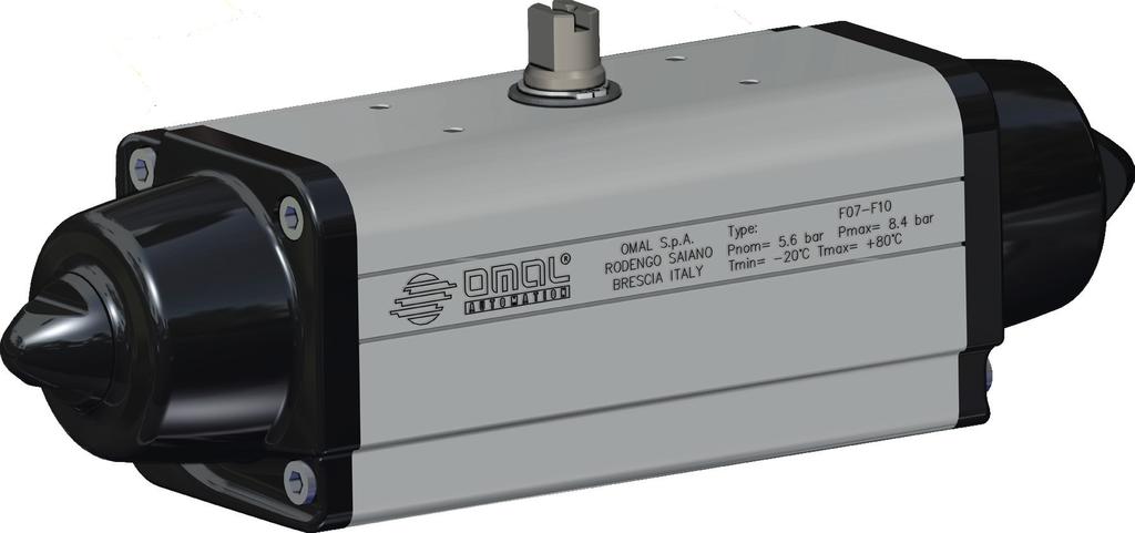
4 Actuator opening, closing and open/close cycle times (sec.). Actuator size 0-90 cycle time SEC 90-0 cycle time SEC Actuator size 0-90 cycle time SEC 90-0 cycle time SEC DAN15 0,04 0,04 SRN15 0,13 0,09 DAN30 0,06 0,07 SRN30 0,14 0,10 DAN45 0,08 0,09 SRN53 0,20 0,17 DAN60 0,10 0,10 SRN60 0,25 0,22 DAN106 0,12 0,13 SRN90 0,31 0,33 DAN120 0,15 0,15 SRN120 0,40 0,37 DAN180 0,20 0,21 SRN180 0,58 0,44 DAN240 0,28 0,25 SRN240 0,65 0,53 DAN360 0,38 0,36 SRN360 0,96 0,72 DAN480 0,46 0,4 SRN480 1,16 0,90 DAN720 0,64 0,59 SRN720 1,65 1,49 DAN960 0,81 0,73 SRN960 2,60 2,14 DAN1440 1,36 1,21 DAN1920 1,59 1,44 The above time table is referred to a standard actuator working cycle at the following tests conditions : Ambient temperature: 18 C 25 C Motive energy operating medium: compressed air at 5,6 bar Nominal cycle: 90 in both directions Load: free DA actuators operate with solenoid valve 5/2 ISO 1-2. While the SR actuators with solenoid valve 3/2. Time tested with Electronic Timer device. NOTE: different working condition such as air pressure, piping connection, filters or solenoid valves, could change the timing of the operations. g. Lubrication The actuators are factory lubricated for the standard working condition life. During maintenance and reassembling OMAL recommends to use TECNOLUBE SYNTHY POLYMER 402, or equivalents. h. Internal wear protection The cylinder is lapped to obtain a surface with fine roughness and is protected with 20 µm technical oxidation. The pistons slide supports are in P.T.F.E. or polyurethane only, no rubber in contact. The use of steel bearings on the Scotch-Yoke system ensures no play and low friction during operation i. External protection OMAL standard actuators are suitable for indoor and outdoor installation. The aluminium body is external protected form corrosion and wear with 20 µm technical oxidation. The cast aluminium end caps are polyester painted. Driving shaft and caps screws are in stainless steel. For aggressive atmosphere and severe environmental condition select the required protection from the external finishes showed in our catalogue or contact directly our technical department. j. Functional Safety The pneumatic actuators are also suitable for installations which require high level of functional reliability, up to SIL3, in compliance with the IEC standard. k. Marking and classification All OMAL actuators bodies are marked with the Manufacturer name and address, the actuator Type code including the Series and - 4

5 Size, and its range of Pressure and Temperatures working conditions and limits. Marking :2009 point 6.1 Name of the company in charge of marketing the product in the E.U. Address of the company in charge of marketing the product in the E.U. Model, operating pressure and temperature. Product code. Month and year of production Working pressures: nominal and maximum Standard flanging MARKING Marking instructions where the temperature is different from the standard one: - low temperature version: T. min.= -50 C T. max=60 C - high temperature version: T. min.= -20 C T. max=150 C DATE OF PRODUCTION - 5


6 3. OPERATION AND ROTATION DIRECTION a. Double Acting The pistons of standard DA actuators are mounted as shown below. This provides the highest torque at the valve start opening for valve clockwise to close. The pistons are then in their outermost position and the end travel stops can be fine adjusted. 2 4 The port 2 is in connection with the cylinder side chambers, supplying the pressurised air in port 2 the standard Double Acting actuator drive shaft rotates counter clockwise to open, while the port 4 is in connection with the intermediate chamber and when pressurised the drive shaft rotates clockwise to close. b. Single Acting, Spring Return fail to Close The pistons of standard SR actuators are mounted as shown below. Although spring force is diminished, the geometry of the mechanism provides a greater torque at the end of the spring stroke. When the actuator is in the valve open position, and the springs are fully compressed, the end of travel stops can be fine adjusted. Caution. In order to avoid suction of dust or dirt inside of the actuator chambers during the spring action, install a filter on the port The port 4 is in connection with the intermediate chamber and when pressurised the drive shaft rotate counter clockwise to open. - 6


7 c. Double Acting operation cycle (DA) d. Simple Acting Spring Return fail to close operation cycle (SR) Important. Special Double Acting version for flow dosing and Spring Return fail to open actuators with different piston positions have different rotation to close and to open: please follow their special instructions. -Connection schema Actuator operation functionality remote control should be done by means of direct solenoid valve connection to the actuator standard interface V/VDI 3845 NAMUR, or by means of pipes screwed on the ports marked with the numbers 2 and 4 and connected to a separate control cabinet. Fig 3.1 Typical air connection schema -Rotation direction. In accordance with the international standard ISO the actuator air ports connection position, location, orientation and form shall be clearly identified and marked with the numerate 2 and 4. Standard Double Acting and Simple Acting Spring Return actuators shall be Clockwise ( CW ) direction to valve Close, and Counter Clockwise ( CCW ) direction to valve Open. - 7
8 4. SAFETY INFORMATION - The actuator should be used within the pressure mentioned limits only, operating the actuator over the pressure limit will damage the internal actuator parts. - Operating the actuator over or under the temperature limits will damage the internal and external parts. - Operating the actuator in corrosive environments without the required external protection will damage the actuator. - Before installation, service or maintenance verify that the actuator is not pressurised, disconnect the air lines and make sure that the air ports are vented - Do not remove the end caps while the actuator is installed in the line, or while the actuator is under pressure. - Do not disassemble the caps end spring cartridge, this operation should be done by OMAL trained personnel only, this operation could causes personal injury. - Before mounting the actuator onto the valve make sure that the valve rotation is according with the actuator operating rotation, and the upper shaft slot orientation is also correct. - Before installing the actuated valve do cycling test for a wile to ensure the correct mechanical mounting and actuator/valve operations. - The actuator installation shall be done according to and in observance with the local and national laws regulation. OMAL cannot be responsible for any damage to people, animals or things due to an improper use of the product. - 8
9 5. INSTALLATION INSTRUCTION The principle of the actuator application is to open and close the connected part turn valve installed in a plant, without the manual operation, by remote control by means of an electric-pneumatic connection. The normal sizing of actuators require a 20%-30% safety margin over the valve breakaway torque to handle valves. Plant design, chemical and physical flow characteristics and environmental condition could increase the safety factor to apply to actuator sizing. Before performing any installation operation, verify the actuator and valve conditions according to the safety notice above described. Moreover the utmost clearness is required during valve installation of the air supply connection to the actuator. All the connection parts such as reductions, joints, plates, brackets and equipment must be clean and dirty free. Before assembling the actuator onto the valve make sure that both items are correctly oriented, depending upon which direction of rotation is required. - Before starting the actuator installation, should be done a visual actuator control to verify its physical condition after transportation and storage. - Control trough the shaft slot or caps the actuator position - Read carefully the OMAL instruction sheet included in the cardboard box - Read the actuator limits and performances marked on the actuator body to verify its suitability - Remove the protection label stickers from the ports Fig 5.1 Actuator control - Before fitting the actuator on the valve, clean the valve and the actuator from the dust and dirt. - Verify the valve position, close or open, and the rotation direction. - Verify the actuator position and rotation according with the valve requirement and operation, especially for Spring Return installation Fail to Close or Fail to Open. - Spring Return Fail to Close actuators are always supplied in the close position. - While Spring Return Fail to Open are always supplied in the open position. - 9
 DIRECT MOUNTING Valve actuator Direct mounting is the best solution to avoid plays between valve stem and actuator drive shaft.")
10 Fig 5.2 Valve/Actuator assembly: (A) direct-mount (B) plate-mount (C) bracket-mount. A B C A) DIRECT MOUNTING Valve actuator Direct mounting is the best solution to avoid plays between valve stem and actuator drive shaft. For a direct mounting you should have the same standard flange connection on valve and actuator as well as the valve stem dimensions that fit perfectly with the actuator drive. Before installation please verify that the actuator and valve flange ISO connections are the same size; verify that the valve stem size and shape is suitable for direct mounting, if necessary use a drive reduction. Fit the valve stem into the actuator drive shaft connection, and bolt together the two ISO flanges. B) MOUNTING PLATE CONNECTION In case direct mounting is not possible cause of little differences in actuator/valve flanges or drives sizes, mounting plates adapters with suitable flanges dimensions allows an easy connection living a sufficient space for the valve/actuator drive adapter. C) BRACKET & JOINT CONNECTION Wherever for technical reason the plant installation requires a distance between actuator and valve, or the valve flange and/or stem are not standard, and in any case, where the valve/actuator connection could not be possible, a bracket and joint is the right answer. The Bracket is a steel bridge that allows to connect the valve with is own flange connection in one side and with the suitable actuator connection onto the opposite side, living a space in between for a steel joint connection. The joint allows a drive connection between the actuator and the valve stem indispensable in case of stem key drive and flat head. Chose the suitable flange bracket and the required joint connections to fix the actuator onto the valve very tight without any plays. OMAL actuator with its draining channels system on the flange connection pattern is especially designed for valve direct mounting. This system allows to drop away any possible flow coming from the valve stem that with valve/actuator direct mounting could damage the actuator. - 10


11 Screw torque wrench setting SIZE TORQUE Nm M5 5-6 M M M M M M M Fig 5.3 Actuator/Valve rotation control and mounting. Type : DAN (Valve closed) Type : DAN (Valve open) - 11

 - 12")
12 Type : SRN (Valve closed) Type : SRN (Valve open) - 12
13 Stroke adjustment. Both actuator versions, Double Acting and Spring Return, are provided as standard with 10 stroke adjustment. a. DAN instruction - Double Acting stroke adjustment. Close adjustment. The stroke adjustment on the actuator mounted on the valve should be done with the valve free of any flow pressure or friction impediments, in addition the actuator shall be disconnected from the air supply and equipment. This operation should be done with the valve/actuator held firmly in the pipeline or in a vice. - Supply the air pressure to port 2 to open the valve, and to position the actuator pistons inward. - Remove the cap nuts ( part N 18 ) and its O-ring ( part N 24 ). - Screw in clockwise direction the screw adjustment ( part N 28 ) in one actuator side only. - Supply the air pressure to port 4 to close the valve and to position the pistons outward and against the adjustment screw, and check the valve close position. - In case the valve position is not correct, repeat the operation from the beginning. - In opposite situation, if, with the air supply in the port 4, the valve is not sufficiently closed, unscrew counter clockwise the adjustment screw ( part N 28 ) backward counter clockwise until the required position has been found. - Obtained the correct valve position, and with the air pressure to the port 4, screw the other adjustment screw up to piston pressing, in this way both adjustment screws are working to stop the pistons simultaneously. - Tightly screw the cap nuts ( part N 18 ) with its sealing O-ring ( part N 24 ) on the end caps to hold the adjustment screws in desired position. - The actuator is now ready to operate correctly. OMAL standard stroke adjustment is max 10, special longer screws are available on request. - 13
14 b. SRN instruction - Single Acting Spring return Fail to Close stroke adjustment. Open adjustment The stroke adjustment on the actuator mounted on the valve should be done with the valve free of any flow pressure or friction impediments, in addiction the actuator shall be disconnected from air supply and equipment. This operation should be done with the valve/actuator held firmly in the pipeline or in a vice. - Remove the cap nuts ( part N 18 ) and its O-ring ( part N 24 ). - Screw, clockwise direction, the screw adjustment ( part N 21 ) in one actuator side only. - Supply air pressure to port 4, and due to the air pressure action the pistons moves to the outward position up to the limits determined by the adjustment screw on the piston head. - Check the valve open position, if the valve is to much open repeat the operation from the beginning. - In opposite case, valve not sufficiently open, with the air supply to the port 4, move the adjustment screw ( part N 21 ) backward counter clockwise until the required position has been found. - Obtained the correct valve position, and with the air pressure to the port 4, screw the other adjustment screw up to piston pressing, in this way both adjustment screws are working to stop the pistons simultaneously. - With pressurised air supply, tightly screw the cap nuts ( part N 18 ) with its sealing O-ring ( part N 24 ) on the end caps to hold the adjustment screws in desired position. - In this condition the actuator is ready to operate correctly. OMAL standard stroke adjustment is max 10, special longer screws are available on request. - 14
15 Close adjustment The stroke adjustment on the actuator mounted on the valve should be done with the valve free of any flow pressure or friction impediments, in addiction the actuator must be disconnected from air supply and equipment. This operation should be done with the valve/actuator well held in the pipeline or in a vice. - Remove the cap nuts ( part N 18 ) and its O-ring ( part N 24 ). - Supply the air pressure to port 4 to open the valve, and position the actuator pistons outward. - Unscrew, counter clockwise direction, both screws in same measure ( part N 21 ). - Stop to supply air pressure to port 4, and due to the spring action the pistons moves to the inward position up to the limits determinate to the adjustment screws on the spring caps ( part N 22 ), ***WARNING - Check the valve close position, if is over closed repeat the operation from the beginning until the desired valve closure position is achieved. - In opposite case, with the valve to much open, with the air supply to the port 4, move both adjustment screws inward, clockwise in same measure. - Without pressurised air supply, tighten the cap nuts ( part N 18 ) with its sealing O-ring ( part N 24 ) on the end caps to hold the adjustment screws in desired position. - In this condition the actuator is ready to operate correctly. ***WARNING: The Spring Return close adjustment is not a mechanical stop that act against the pistons travel or the shaft rotation, but the screws limits the spring travel and the pistons without any force standstills. In this condition the shaft is not stopped and theoretically could be moved to the total closing position, adjustments of closing and opening can not be performed both. OMAL standard stroke adjustment is max 10, special longer screws are available on request. This adjustment table represent the average drive variation angle α for each full turn of the adjustment screw β. - 15
16 For each 1 of drive variation α 1 the adjustment screw is to be rotate as β 1. *The below table data is referred to the standard stroke adjustment only (10 ). For longer screw adjustment please contact technical commercial department. ACTUATOR SIZE ADJUSTMT SCREW ROTATION ANGLE SHAFT VARIATION ANGLE AFTER ADJUSTMT ADJUSTMT SCREW ROTATION ANGLE SHAFT VARIATION ANGLE AFTER ADJUSTMT β α β α DAN ' DAN ' SRN ' DAN ' SRN ' DAN ' SRN DAN ' SRN ' DAN SRN ' DAN ' SRN ' DAN ' SRN ' DAN SRN DAN ' SRN ' DAN SRN DAN ' SRN '
17 6. MATERIALS AND THEIR DURABILY Life time 20 years or number of cycles as per ( see table below ). Nominal torque (a) Nm Piston or vane actuator Minimum number of cycles (b) Maximum stroking time for testing, based on 0-90 s (c) a. Based on ISO b. One cycle consists of nominal 90 angular travel in both directions (i.e. 90 to open + 90 to close). For angular travel other than 90, the endurance shall be agreed between the purchaser and the manufacturer/supplier. c. For thermoplastic actuators the minimum number of cycles shall be Should it be necessary to replace its pistons sealing, this operations must be done by OMAL trained people with proper tools, we recommend to return the actuator to OMAL where the actuator will be overhauled and than tested for a correct replacement. On request OMAL will be willing to provide its sealing Kits. WARNING: OMAL declines any responsibility for the products repaired by third parties - 17
18 Fig 6,1 Actuator components and material list. POS. NOMINATION Q. MATERIALS STANDARDS 1 Cylinder 1 Aluminium alloy AW 6063 Anodized 2 Piston 2 Aluminium alloy AB Cap 2 Aluminium alloy AB46100 Painted 4 Shaft 1 Stainless steel AISI DIN Scotch yoke 1 Steel alloy UNI 90MnVCr8Ku - DIN Ardenered 6 Support bush 1 Acetalitic resin 7 Shaft support 1 Acetalitic resin 8 Bush 2 Steel alloy UNI 110w4Ku - DIN Rotative sleeve 2 Steel alloy UNI 6364A - DIN * Dynamic seal (piston) 2 Polyurethane 11* Piston s support 4 RPTFE-CF 12* Piston o-ring 2 Nitrilic rubber 13* O-ring (upper sealing shaft ) 1 FKM 14 External support ring 1 Aluminium alloy 15 Washer 1 Stainless steel UNI DIN Seeger 1 Stainless steel UNI DIN * O-ring (low sealing shaft ) 1 FKM 18 Nut 1 Aluminium alloy AB46100 Painted 19* Cap o-ring 2 Nitrilic rubber 20 Screw 8 Stainless steel AISI DIN Spring loading screw 2 Steel UNI 3740/65 8G Galvanized 22 Spring cap 2 Steel DIN Galvanized 23 Spring 2 Steel DIN * O-ring 2 Nitrilic rubber 25 External elastic pin of the yoke 1 Steel DIN Internal elastic pin of the yoke 1 Steel DIN Centering ring 1 Aluminium alloy DIN AIMgSiPb Anodized 28 Stroke adjustment screw 2 Stainless steel AISI DIN * Parts included in the spare parts kit. - 18

19 7. MAINTANCE The OMAL SpA actuator, when installed and used properly, does not require maintenance, under normal use, as it s provided with sufficient lubrication for standard duration. Send the actuator directly to for inspection or extraordinary maintenance If the cap or piston seals need to be replaced, can supply a kit containing spare parts. WARNING: The seals must be replaced by qualified personnel and with the appropriate tools. declines all responsibility for products that are repaired by third parties REPLACING THE SEALS a) Disassembly Actuator disassembly operation must done with the actuator free from any pneumatic and electric connection and dismounted from the valve. Verify that the actuator is air bag free, and the spring return actuator is completely in its springs rest position. Check that the air port 2 and 4 are absolutely vented. Use proper tools only. a.1) Loosen the end cap screws ( part N 20 ) in cross sequence to remove the end caps ( part n 3 ), in case of force on the screws that means that the actuator is still under air or spring action and the operation should be discontinued until the action is removed. The end caps contain a sealing O-ring ( part N 19 ) on its seat that should be checked before replacement. Caution. The Spring Return end caps cartridges (Parts N ) are a safety device, where the preloaded spring is set to avoid the dangerous spring jumping. Do not release the screw ( part N 21 ) to remove the spring from its seat, this operation must be done by OMAL technician only a.2) B) Hold the actuator in the vice and rotate the drive shaft until the pistons ( part N 2 ) are released form the scotchyoke groves ( part N 5 ), then slip off the pistons from the cylinder ( part N 1 ). Do not use compressed air to remove the pistons from the body, this operation could cause personal injuries. - 19
 When the components are disassembled, they should be properly cleaned and wear checked prior to being greased and reassembled.")
20 a.3) The dynamic seal ( part N 10 ), O-ring ( part N 12 ) and supports ( part N 11 ) should be checked before replacement. Do not use sharp tools to cut the dynamic seal and O-ring or remove the supports from the piston as this may cause furrows or marks. a.4) When the components are disassembled, they should be properly cleaned and wear checked prior to being greased and reassembled. In case the sealing parts are too much worn out use new parts from the spare parts kit. WARNING: Due to OMAL scotch-yoke shaft blow-out security system the shaft disassembly operation must be carried out by OMAL technician only. b) Assembly b.1) O-ring ( part N 12 ) and dynamic seal ( part N 10 ) shall be greased and mounted onto the piston seat using a proper conical tool ( see the drawing ) that allows an easy and perfect slip-in of the items without any damages. b.2) Push into its piston seats the P.T.F.E. supports ( part N 11 ). b.3) Grease the pistons ( part N 2 ) on the replaced parts ( parts N ), and the piston bearings ( part N 8 ). b.4) Grease the internal cylinder surface ( part N 1 ). - 20
21 b.5) Position the scotch-yoke shaft ( part N 5 ) in order to have the groves in position for the pistons insertion and the right shaft required direction of rotation. b.6) Insert the pistons ( part N 2 ), using a proper conical tool ( see the drawing ), in the scotch-yoke grooves ( part N 5 ) and press simultaneously the two pistons inside of the cylinder ( part N 1 ). The OMAL scotch-yoke system will avoid pistons misalignment. Holding the actuator on a vice rotate the shaft to verify the shaft rotation direction and the easy movement. b.7) Replace the sealing O-ring ( part N 19 ) on its caps seat ( part N 3 ) and grease it. Fit the end caps to the body screwing the screws in cross ( part N 20 ). NOTE: For the screw torque wrench setting see paragraph 5. INSTALLATION INSTRUCTION Holding the actuator in a vice, rotate the shaft to check the direction of rotation and its correct movement. DAN Inlet Conical tool SRN Inlet Conical tool - 21
.")
22 8. SPECIAL VERSIONS OMAL manufactures and supplies special actuators versions for specific actuator use and environmental. a)external protections. All the standard version could be supply with different external protection according with the plant ambient working condition ( see OMAL catalogue or contact OMAL commercial team ). b)stainless Steel Actuators For food and chemical plants OMAL manufacture a Stainless Steel version. The body and all the external part are made in stainless steel. The rotary system is the same Scotch-Yoke used for the standard actuators. For the stainless steel actuators performances please refers to the standard actuators data tables. c)simple Acting spring return Fail to Open. Spring Return Fail to Open actuators are required when in case of the pressurised air or electrical power supply are off the valve should be automatically opened. In the fail to open actuators the pistons are inserted into the cylinder like the Double Acting version, and due to the spring force the actuator is Normally Open. WARNING: Nominal torque and torque performances in Spring return Fail to Open version, due to its construction, are different from the Spring Return Fail to Close standard versions. For sizing and application please refer to OMAL technical department. Simple Acting Spring Return fail to open operation cycle. - 22
23 d) This double acting DAN special version, with the pistons rotated and extra long adjustment screws, limits the actuator/valve travel in the open position and is used when the valve should never be totally open, but limited up to 45% of its capacity. WARNING: Double Acting (DAN) and Spring Return (SRN) special version develop different torque forces and before installation and maintenance please consult OMAL technical department for their technical data and torque diagrams. 9. STORAGE The OMAL actuator has been packaged to provide protection during shipment, however, it can be damaged in transport. Prior to storage, inspect the actuator for shipping damage. Keep the actuators in their original packing box during storage. It is recommended to keep the actuators in a clean and dry environment at temperatures between -10 C and +60 C until ready for use. The actuator has two air ports, which are closed by labels for prevent liquids or others material to entering in the actuator during storage. If the actuators are to be stored for a long period of time before installation, it is recommended to stroke them periodically to prevent setting of the seals. Store the actuators indoors to protect them from humidity and dust. - 23
24 10. TROUBLHOOTING POTTIAL EFFECT OF FAILURE POTTIAL CAUSE OF FAILURE SOLUTION Lack of supply Verify that the actuator has been connected to the pneumatic line correctly Loss or reduction of the supplied torque Verify that the supply pressure value corresponds to the functioning requirements Air supply not enough to produce the required torque (See actuator data plate). Air leakage from the seals Verify that the screws are completely tightened Stem O-ring seal damaged Leaks from the stem upper or lower Damages on the body seals Shaft damaged Contact for repair Leakage from cylinder caps Seals damaged Replace the seals (see Maintenance chapter) Replace the piston seals (see Maintenance chapter) Piston sealing damaged Leakage from the ports after maneuver Cylinder body damaged Contact for repair Increase of valve maneuver torque Verify the valve release torque and possibly replace with a new one Air supply not enough to produce the Insufficient rotation angle required torque Increase the air supply Mechanical stop (if there) not duly adjusted Adjust the stops by increasing the stroke Wrong connection between the actuator and the valve stem Check the connection elements between the valve and the actuator 11. DISPOSAL OF PRODUCTS AT THE D OF THEIR LIFE CYCLE The OMAL products are designed so that when they are at the end of their life cycle they can be completely disassembled, separating the different materials for the proper disposal and/or recovery. All materials have been selected in order to ensure minimal environmental impact, health and safety of personnel during their installation and maintenance, provided that, during use, they are not contaminated by hazardous substances. The personnel in charge of the product disposal/recovery, must be qualified and equipped with appropriate personal protective equipment (PPE), according to the product size and the type of service for which the device was intended. The management of waste generated during the installation, maintenance or due to the product disposal, is governed by the rules in force in the country where the product is installed, in any case, the following are general guidelines: - The metal components (aluminium/steel) can be restored as raw material; - Seals/sealing elements (NBR, FKM, FVMQ...), as contaminated by fluids from other materials and lubrication, must be disposed of. - The packaging materials that come with the product, should be transferred to the differentiated collection system available in the country. - 24
25 12. CLARATION OF CONFORMY The actuators have been designed, manufactured and tested to meet the requirements of the following European standards and are marked, where provided, with the relative CE conformity marking: /42/EC Directive Machinery ; /34/EU Directive Equipment and protective systems intended for use in potentially explosive atmospheres (ATEX). - Regulation (EC) No 1907/2006 and successive Concerning the Registration, Evaluation, Authorization and Restriction of Chemicals (REACH). - 25
BR 31a Rack-and-pinion Actuator,
 Operating, assembly and maintenance instructions BR 31a Rack-and-pinion Actuator, SRP and DAP 1. General These instructions are intended to support the user in the assembly, maintenance, and repair of
Quarter turn actuator DAPS..R..-F..
 Quarter turn actuator DAPS..R..-F.. Festo AG & Co. KG Postfach D-73726 Esslingen +49 711 347-0 www.festo.com (en) Operating instructions 8030408 1309g [8030416] Original: de Quarter turn actuator DAPS..R..-F.....
aero 2 -IOM aero 2 ACTUATOR - INSTALLATION, OPERATION & MAINTENANCE MANUAL
 Instruction DP00226 May 2015 IMPORTANT SAFETY WARNINGS A. Before carrying out any repair or maintenance on the actuator, make sure that the pressure supply lines and electrical connections have been safely
Mounting and Operating Instructions EB 8222 EN. Type 3310/AT and Type 3310/3278 Pneumatic Control Valves. Type 3310 Segmented Ball Valve
 Type 3310/AT and Type 3310/3278 Pneumatic Control Valves Type 3310 Segmented Ball Valve Fig. 1 Type 3310/3278 with positioner Fig. 2 Type 3310/AT Mounting and Operating Instructions EB 8222 EN Edition
CO 3-WAY PNEUMATIC VALVE INSTRUCTION MANUAL 2080
 CO 3-WAY PNEUMATIC VALVE INSTRUCTION MANUAL 2080 STI S.r.l has taken every care in collecting and verifying the documentation contained in this Instruction Manual. The information herein contained are
Angle seat valve with piston actuator VZXA-...-K
 Angle seat valve with piston actuator VZXA-...-K Instructions Operating (Translation of the original instructions) Festo AG & Co. KG Ruiter Straße 82 73734 Esslingen Germany +49 711 347-0 www.festo.com
Installation & Operation Manual
 Installation & Operation Manual (I-TORK PDS Series Pneumatic Actuator) PDS-M0108/1010 74-6, Chun Ui-Dong, Won Mi-Gu, Bucheon, Kyoung Ki-Do, Korea Tel : 82-2-855-1365, 66 Fax : 82-2-855-1367 E-mail : roy75@i-tork.com
Pneumatic actuator Assembly & maintenance procedures
 Pneumatic actuator Assembly & maintenance procedures SPRING RETURN ACTUATOR Fig.7901 DOUBLE ACTING ACTUATOR Fig.7902 - LCIE 05 AR 022 2 CONTENTS 1. Applicable Range... page 4-6 2. General Information...
Angle seat valve with diaphragm actuator VZXA-...-M
 Angle seat valve with diaphragm actuator VZXA-...-M Instructions Operating (Translation of the original instructions) Festo AG & Co. KG Ruiter Straße 82 73734 Esslingen Germany +49 711 347-0 www.festo.com
USER MANUAL. Pneumatic actuator - AL WARNING! WARNING! WARNING!
 Type and Design DA = Double Acting. Actuator with pneumatic operation in both directions. SR = Spring Return. Actuator with spring return. RC 210, 230, 250 and 270 have 1 piston. RC 220, 240, 260, 265
C Series Pneumatic Rack & Pinion Rotary Actuators
 Allied Flow Controls, Inc. C Series Pneumatic Rack & Pinion Rotary Actuators Spring Return & Double Acting Features and Benefits Torque Range at 0 Psig Air Pressure: Double Acting: -,00 lbf-in Spring Return:
Angle seat valve with piston actuator VZXA-...-K
 Angle seat valve with piston actuator VZXA-...-K Festo AG & Co. KG Postfach 73726 Esslingen Germany +49 711 347-0 www.festo.com 3 Further information Accessories www.festo.com/catalogue Spare parts www.festo.com/spareparts
Features PNEUMATIC ACTUATORS. Stainless steel pneumatic actuators Spring return SR from bar. Technical features. Working condition
 OMAL S.p.a. Via Ponte Nuovo, 11-25050 Rodengo Saiano (BS) ITALY Phone +39 0308900145 - Fax +39 0308900423 Booked in the Enterprise Register of: Brescia number 1661640175 Share capital completely deposited:
4th GENERATION PNEUMATIC ACTUATOR
 4th GENERATION PNEUMATIC ACTUATOR Catalogue N : 4thG./99-B MULTI-FUNCTION INDICATOR The multi-function indicator which is supplied as standard on 4th Generation Actuator and manufactured in composite material
Type 0283, Operating Instructions. Bedienungsanleitung Manuel d utilisation. 2/2-way solenoid valve 2/2-Wege-Magnetventil Électrovanne 2/2 voies
 Type 0283, 0293 2/2-way solenoid valve 2/2-Wege-Magnetventil Électrovanne 2/2 voies Operating Instructions Bedienungsanleitung Manuel d utilisation Contents 1 The operating instructions...2 2 Intended
MANUAL - PNEUMATIC ACTUATORS, SERIES DA & SR - 1 -
 MANUAL - PNEUMATIC ACTUATORS, SERIES DA & SR - 1 - DOUBLE ACTING ACTUATOR DA SPRING RETURN ACTUATOR SR - LCIE 05 AR 022 MANUAL - PNEUMATIC ACTUATORS, SERIES DA & SR - 2 - Content 1. Applicable Range 3
MTC Series. Double Acting and Spring Return Actuator and Accessories. MasterTorq. Pneumatic Actuators. Atex Class 2
 Double Acting and Spring Return Actuator and Accessories MTC Series TM Pneumatic Actuators Atex Class Operations Double Acting A B A B By supplying air to Port A, pressure is applied to the center chamber
Mounting and Operating Instructions EB 8135/8136 EN. Series V2001 Valves Type 3535 Three-way Valve for Heat Transfer Oil
 Series V2001 Valves Type 3535 Three-way Valve for Heat Transfer Oil Type 3535 Three-way Valve with bellows seal and rod-type yoke (partial view) Mounting and Operating Instructions EB 8135/8136 EN Edition
Type Operating Instructions. Bedienungsanleitung Manuel d utilisation. 2/2-way solenoid valve 2/2-Wege-Magnetventil Électrovanne 2/2 voies
 Type 5404 2/2-way solenoid valve 2/2-Wege-Magnetventil Électrovanne 2/2 voies Operating Instructions Bedienungsanleitung Manuel d utilisation Contents 1 Operating instructions...2 2 Intended use...3 3
ACM SERIES Pneumatic Actuators
 ACM SERIES Pneumatic Actuators ATEX ACHEM Controls Add: North Service Road #., Oakville, Ontario Canada Phone: --34 Cell: 0--004 E-mail: Kevin.armstrong@achemgroup.com www.achemgroup.com Skype: achemkevin
EL-O-Matic F-Series Rack and Pinion Pneumatic Actuators
 EL-O-Matic F-Series Rack and Pinion Pneumatic Actuators Product Data Sheet EF.00.00.EN Rev. 8 January 2018 High quality and economical actuator Improve plant and operator safety Reliable and flexible in
Type Operating Instructions. Bedienungsanleitung Manuel d utilisation. 2/2-Way Solenoid Valve 2/2-Wege-Magnetventil Électrovanne à 2/2 voies
 Type 5282 2/2-Way Solenoid Valve 2/2-Wege-Magnetventil Électrovanne à 2/2 voies Operating Instructions Bedienungsanleitung Manuel d utilisation 1 OPERATING INSTRUCTIONS The operating instructions contain
INSTALLATION, OPERATION & MAINTENANCE MANUAL
 Rack & Pinion Pneumatic Actuators INSTALLATION, OPERATION & MAINTENANCE MANUAL QSM, Inc. 127 Village Lane Easley, SC 29642 U.S.A. Ph: (864) 605-0150 Fax: (864) 605-0830 www.tru-flo.com TABLE OF CONTENTS
BUTTERFLY VALVE 27 SERIES Pneumatic actuator - El-O-Matic
 C D E FIGURE: PD: pneumatic actuator, double acting PE: pneumatic actuator, spring return PEO: pneumatic actuator, spring return, normally open BUTTERFLY VALVE 27 SERIES Pneumatic actuator - El-O-Matic
MANUAL. Pneumatic actuator - AL Type and Design. Operating Medium. The Application of the Scotch Yoke Construction WARNING!
 Ref. 5.400B_UK 20150511 www.axellarsson.se Pneumatic actuator AL 77200 Type and Design DA = Double Acting. Actuator with pneumatic operation in both directions. SR = Spring Return. Actuator with spring
Type Operating Instructions. Bedienungsanleitung Manuel d utilisation
 Globe control valve, pneumatically operated Actuator sizes 40 mm - 125 mm, Nominal diameter DN10-65 Kolbengesteuertes Geradsitzventil Antriebsgrößen 40 mm - 125 mm, Nennweiten DN10-65 Vanne à siège droit
Bettis RPE-Series Rack and Pinion Pneumatic Actuators
 Bettis RPE-Series Rack and Pinion Pneumatic Actuators Product Data Sheet September 2017 BE.00.00 Rev. 3 High quality and economical actuator Improve plant and operator safety Riable and flexible in process
Type 5411, Operating Instructions. Bedienungsanleitung Manuel d utilisation
 Type 5411, 5413 3/2 or 4/2 way solenoid valve 3/2 oder 4/2-Wege-Magnetventil Électrovanne 3/2 ou 4/2 voies Operating Instructions Bedienungsanleitung Manuel d utilisation 1 THE OPERATING INSTRUCTIONS The
Type Operating Instructions. Bedienungsanleitung Manuel d utilisation. 2/2-Way Solenoid Valve 2/2-Wege-Magnetventil Électrovanne à 2/2 voies
 Type 5282 2/2-Way Solenoid Valve 2/2-Wege-Magnetventil Électrovanne à 2/2 voies Operating Instructions Bedienungsanleitung Manuel d utilisation Contents 1 Operating Instructions... 2 2 Authorized use...
AV INSTALLATION, OPERATION & MAINTENANCE MANUAL
 Rack & Pinion Pneumatic Actuators AV INSTALLATION, OPERATION & MAINTENANCE MANUAL AVCS PO Box 68172 Minneapolis, MN 55418 TABLE OF CONTENTS CHAPTER 1: PRODUCT DESCRIPTION 3 CHAPTER 2: TECHNICAL FEATURES
Flow Line Controls. Installation & Operations Manual SERIES 20/21 Pneumatic Actuators
 Flow Line Controls Installation & Operations Manual SERIES 20/21 Pneumatic Actuators Flow Line Controls, Inc. P.O. Box 677 Schriever, LA 70395 Phone: 985-414-6003 Toll Free 1-800-815-9226 Fax 985-414-6072
PNEUMATIC ACTUATORS ASSEMBLY & MAINTENANCE PROCEDURES. Ref. Doc. MMMACTREGDRE English Rev.2 January 2012 ADA & ASR SERIES DOUBLE ACTING ACTUATOR ADA
 ADA & ASR SERIES SPRING RETURN ACTUATOR ASR DOUBLE ACTING ACTUATOR ADA - LCIE 05 AR 022 V R 1 REVIEW CONTROL PROCEDURE REF. DOC. MMMACTREGDRE Rev. Date Carried out by Approved Description 0 02-01-2006
DelTorq Series 21 ACTUATOR
 Jamieson Equipment Company DelTorq Series 21 ACTUATOR INSTALLATION, OPERATION AND MAINTENANCE MANUAL ENGINEERING DATA SHEET E.D.S. NO EDS055 ISSUE DATE - -- 20/01/2007 (Please read the entire instructions
Operation and Maintenance Instructions for Bettis GVO-C Series GVO-CLP-SR Pneumatic Actuators
 Part Number: GVO-CLP-SR.IOM.1003, Rev. 0 Release: March 2016 Operation and Maintenance Instructions for Bettis GVO-C Series GVO-CLP-SR Pneumatic Actuators Part Number: GVO-CLP-SR.IOM.1003, Rev. 0 Table
Operating and Installation Instructions Diaphragm Vacuum Pumps and Compressors
 Operating and Installation Instructions Diaphragm Vacuum Pumps and Compressors Type range: UN813.3ANI UN813.4ANI UN813.3ANDCB UN813.4ANDCB UN813.5ANI Fig. 1: UN813.3ANI Fig. 2: UN813.4ANI You have selected
SC/V - VALVE ACTUATOR SPRING RETURN INSTRUCTION MANUAL 5018
 SC/V - VALVE ACTUATOR SPRING RETURN INSTRUCTION MANUAL 5018 STI S.r.l has taken every care in collecting and verifying the documentation contained in this Instruction Manual. The information herein contained
IOM Manual. IOM Manual. Series 20/21.
 IOM Manual IOM Manual Series 20/21 www.flowlinevalves.com Flow Line Valve and Controls, L.L.C. 110 Main Project Road Schriever, LA 70395 P.O. Box 677 Schriever, LA 70395 Phone 985-414-6004 * Toll Free
Type 6213 EV, 6281 EV
 Type 6213 EV, 6281 EV 2/2-way solenoid valve 2/2-Wege-Magnetventil Électrovanne 2/2 voies Operating Instructions Bedienungsanleitung Manuel d utilisation 1 OPERATING INSTRUCTIONS The operating instructions
EL-O-Matic F-Series Rack and Pinion Pneumatic Actuators
 Product Data Sheet October 2016 EF.00.00.EN Rev. 7 EL-O-Matic F-Series Rack and Pinion Pneumatic Actuators High quality and economical actuator Improve plant and operator safety Reliable and flexible in
Bettis RPE-Series Rack and Pinion Pneumatic Actuators
 Rack and Pinion Pneumatic Actuators BE.00.00 Rev. 7 March 2019 High quality and economical actuator Improve plant and operator safety Reliable and flexible in process control Increase serviceability BEG.01.00.EN,
Spin-on filter according to Bosch Rexroth standard: Type 50 SL 30 to 80D. Features. Contents. RE Edition:
 Spin-on filter according to Bosch Rexroth standard: Type 50 SL 30 to 80D RE 51476 Edition: 2015-06 Nominal sizes: 30 to 80D Connection up to G1; SAE 10 56558_d Features Spin-on filters are used in hydraulic
VMH. www. delta-elektrogas.com. Safety shut off valves for gas with hydraulic actuator DN65 DN200 EE
 VMH Safety shut off valves for gas with hydraulic actuator DN65 DN200 www. delta-elektrogas.com EE168-0513 VMH Contents Description.. 3 Features.. 3 Functioning and application. 4 Special versions and
Note: the numbers in parenthesis refer to the components in the exploded view of page 3 for UT-0 thru UT-6.5 and page 4 for UT-7 and UT-8.
 Note: the numbers in parenthesis refer to the components in the exploded view of page 3 for UT-0 thru UT-6.5 and page 4 for UT-7 and UT-8. CAUTION: Remove dust from the actuator that may cause sparks;
Operating Instructions. Pneumatic Control Valve Low Temperature. Type Series GS3
 Operating Instructions Pneumatic Control Valve Low Temperature Type 8026 Series GS3 With: Digital Positioner Type 8048 Electro-pneumatic Positioner Type 8047 Pneumatic Positioner Type 8047 Version: 03/2006
Spin-on filter according to Bosch Rexroth standard. Type 7 SL ; 7 SLS Features. Contents. RE Edition: Replaces: 01.
 Spin-on filter according to Bosch Rexroth standard Type 7 SL 30 260; 7 SLS 90 260 RE 51426 Edition: 2015-03 Replaces: 01.10 Nominal sizes: 7 SL 30 260; 7 SLS 90 260 Nominal pressure 7 bar [101 psi] Connection
Twin Power. Manual. Pneumatic Multiturn actuator in Standard and ATEX design WARNING! WARNING! Mounting. Assembly example
 Top Quality Valve Actuators Made in Sweden Twin Power Manual Pneumatic Multiturn actuator in Standard and ATEX design Mounting The Twin Power actuator works beyond reproach in all positions. Valves with
ONYX VALVE CO MODEL CAR, CAP-PFO Installation & Maintenance
 ONYX VALVE CO MODEL CAR, CAP-PFO Installation & Maintenance OPERATION: (4-2010) The Onyx series CAR-PFO and CAP-PFO pinch valves fail open on loss of air. The simple spring and air bag arrangement drives
516VX1VSSBIPD Pneumatic actuator - El-O-Matic
 DN B 00 mm D E 56VXVSSBIPD Pneumatic actuator - El-O-Matic F E A L DIMENSIONS: (mm) DN L A B PD PE PD D E F Kg PE D E G Kg 5 5 53 6 25 266 286 59, 0 239 259 20 5,7 20 20 52 53 25 273 293 59, 65 258 278
flowserve.com Limitorque LRP Limitorque Rack & Pinion Pneumatic Actuator
 flowserve.com Limitorque LRP Limitorque Rack & Pinion Pneumatic Actuator 1 LRP Limitorque Rack and Pinion Actuator Series Limitorque is the brand customers trust when safe, reliable and robust valve automation
BALL VALVE - 340BA SERIES Pneumatic actuator - El-O-Matic
 C D E BALL VALVE - 30BA SERIES Pneumatic actuator - El-O-Matic FIGURE: PD: Pneumatic actuator, double acting PE: Pneumatic actuator, spring return G F DIMENSIONS: (mm) Ø DN C PD PE PD D E F Kg PE D E G
TECHNICAL MANUAL MT029
 Ed.2008 Rev.B REFLUX 919 TECHNICAL MANUAL MT029 INSTALLATION, COMMISSIONING AND MAINTENANCE ISTRUCTIONS TABLE OF CONTENTS Chapter Page 1. AIM 4 2. DESCRIPTION OF THE VALVE 4 3. IDENTIFICATION OF THE VALVE
KE-M02 configuration Configuratie documentatie documentation KE-M02
 Configuratie documentatie KE-M02 1/32 2/32 3/32 4/32 5/32 General Technical Data for Compact Power Module KE series Through the years DCOC has developed a highly evolved modular system resulting in powerful,
Bray/ VAAS Slurry Series Knife Gate Valve 760/762/765/766/767/768 Series Operation and Maintenance Manual
 Bray/ VAAS Knife Gate Valve 760/762/765/766/767/768 Series Table of Contents Definition of Terms 1 Safety Instructions 1 Introduction 2 Unpacking 2 Storage 2 Installation 3 Commissioning 3 Cylinder-Operated
SERIES 15 PNEUMATIC ACTUATOR CONTENT PNEUMATIC ACTUATOR ZT SERIES PNEUMATIC ACTUATOR... 1 AW SERIES PNEUMATIC ACTUATOR...
 CONTENT... 1-27 ZT SERIES... 1 AW SERIES... 19 reserves the right to change specifications without notice. i ZT SERIES INTRODUCTION The ZT series pneumatic actuator is one of the best designs in the market,
CATALOGUE+PRICELIST ALUMINIUM ROTARY ACTUATORS SERIES AC-A 0-90 ACG AUTOMATION CENTER GERMANY GMBH & CO. KG
 CATALOGUE+PRICELIST 2.011 ALUMINIUM ROTARY ACTUATORS SERIES AC-A 0-90 DESIGN AND STRUCTURE Design and structure Our newly-designed AC-A Series Pneumatic Actuator is aluminum rack & pinion actuators in
CVS Rack and Pinion Pneumatic Actuator
 Instruction Manual CVS Rack and Pinion Pneumatic Actuator Introduction These instructions apply specifically to the CVS Rack and Pinion pneumatic actuator. This manual provides sizing, maintenance, operation,
Easytork Vane Actuator IOM
 Easytork Vane Actuator IOM General Storage The Easytork Vane Actuator ( EVA ) is a high-quality product and as such must be handled, transported and stored with care. Prior to storage, inspect the actuator
Storage, operating and maintenance instructions for AZ plug valves and Standard valves
 ARMATUREN Plug - Valves metallic with PTFE Sleeve 2-7 way Storage, operating and maintenance instructions for AZ plug valves and Standard valves Plug - Valves FEP/PFA - lined, 2-3 way Butterfly - Valves
Type Operating Instructions. Bedienungsanleitung Manuel d utilisation. 2/2-way solenoid valve 2/2-Wege-Magnetventil Électrovanne 2/2 voies
 Type 6027 2/2-way solenoid valve 2/2-Wege-Magnetventil Électrovanne 2/2 voies Operating Instructions Bedienungsanleitung Manuel d utilisation 1 OPERATING INSTRUCTIONS The operating instructions contain
BALL VALVE SERIES Pneumatic actuator - El-O-Matic
 C D E BALL VALVE - 390 SERIES Pneumatic actuator - El-O-Matic FIGURE: PD: Pneumatic actuator, double acting PE: Pneumatic actuator, spring return G F DIMENSIONS: (mm) Ø DN C PD PE PD D E F Kg PE D E G
BW - BIG VOLUME BOOSTER INSTRUCTION MANUAL 2072
 BW - BIG VOLUME BOOSTER INSTRUCTION MANUAL 2072 STI S.r.l has taken every care in collecting and verifying the documentation contained in this Instruction Manual. The information herein contained are reserved
RACK & PINION ACTUATORS 2R40 to 2R1750 Series Installation & Maintenance Manual
 TRIAC 2R Series Actuators: Attention: Instructional videos on some of the information provided below can be found on our website (http://www.a-tcontrols.com/videos/). Description Section Installation of
Operating Instructions. Angle Seat Control Valve. Type 7020
 Operating Instructions Angle Seat Control Valve Type 7020 With: Digital Positioner Type 8048 Electro-pneumatic Positioner Type 8047 Pneumatic Positioner Type 8047 Version: 02/2006 Manual-7020e.doc Art.-No:
Type Operating Instructions. Bedienungsanleitung Manuel d utilisation
 Type 0131 2/2- or 3/2-way solenoid valve 2/2- oder 3/2-Wege-Magnetventil Électrovanne 2/2 ou 3/2 voies Operating Instructions Bedienungsanleitung Manuel d utilisation 1 OPERATING INSTRUCTIONS The operating
PNEUMATIC RACK & PINION ACTUATOR
 PNEUMATIC RACK & PINION ACTUATOR series RA SERVOVALVE spa Via Quasimodo 27-20010 S.STEFANO TICINO (MI) PHONE: 0039-029748461 FAX: 0039-0297484646 E-mail: servovalve@servovalve.it RA Rev. 0/15 SERIES RA
DelTech Controls L.L.C.
 DelTech Controls L.L.C. DelTorq Series 20 ACTUATORS TECHNICAL DATA SHEET T.D.S. NO. 20 105 / R1 ISSUE DATE : NOV 2004 INSTALLATION, OPERATION AND MAINTENANCE MANUAL Guarantee : ( Please read the entire
BUTTERFLY VALVE SERIES Pneumatic actuator - El-O-Matic
 B C D BUTTERFLY VALVE - 223 SERIES Pneumatic actuator - El-O-Matic FIGURE: PD: Pneumatic actuator, double acting PE: Pneumatic actuator, spring return G F L DIMENSIONS: (mm) DN L B PD PE PD C D F Kg PE
BALL VALVE SERIES Pneumatic actuator - El-O-Matic
 B C D E BALL VALVE - 350 SERIES Pneumatic actuator - El-O-Matic FIGURE: PD: Pneumatic actuator, double acting PE: Pneumatic actuator, spring return G F DIMENSIONS: (mm) Ø DN B PD PE PD C D E F Kg PE C
Filtrec elements are tested according to ISO 2941, ISO 2942 and ISO 23181
 Common HYDRAULIC FILTRATION Side wall mounting suction filters Technical Information Connection Ports: 1-1 1/4-1 1/2 BSP (other thread options on request) 1 1/2 SAE J518-3000/M12 Housing Materials: Cover:
BALL VALVE SERIES Pneumatic actuator - El-O-Matic
 C D E BALL VALVE - 1370 SERIES Pneumatic actuator - El-O-Matic FIGURE: PD: Pneumatic actuator, double acting PE: Pneumatic actuator, spring return G F L DIMENSIONS: (mm) Ø L C PD PE PD D E F Kg PE D E
BALL VALVE HIT SERIES Pneumatic actuator - El-O-Matic
 B C D E BALL VALVE - 516 HIT SERIES Pneumatic actuator - El-O-Matic FIGURE: PD: Pneumatic actuator, double acting PE: Pneumatic actuator, spring return G F A L DIMENSIONS: (mm) DN L A B PD PD C D E F Kg
RCI200 Range. Compact Scotch-Yoke Actuators for Quarter-Turn Valves. Redefining Flow Control
 RCI200 Range Compact Scotch-Yoke Actuators for Quarter-Turn Valves Redefining Flow Control Rotork Actuators Quality Controlled Since the company was founded in 1957, Rotork has become the standard for
ONYX VALVE CO MODEL DAO-PFC Installation & Maintenance
 ONYX VALVE CO MODEL DAO-PFC Installation & Maintenance OPERATION: (4-2010) The Onyx DAO-PFC pinch valve is an open frame valve without housing enclosure and fails closed on loss of air. The actuator drives
PNEUMATIC ACTUATOR FIG. PD - PE
 FIG. PD - PE New design (El-O-Matic type F) Single acting type PE (+ PD up to 100) Available from size12 up to 600 Double acting type PD Available in size 150 up to 600 Old design (El-O-Matic type E) Single
BUTTERFLY VALVE - N1234 SERIES Pneumatic actuator - El-O-Matic
 B C D BUTTERFLY VALVE - N123 SERIES Pneumatic actuator - El-O-Matic FIGURE: PD: Pneumatic actuator, double acting PE: Pneumatic actuator, spring return G F L DIMENSIONS: (mm) DN L B PD PE PD C D F Kg PE
VQ400M SERIES CLASS A COMBINATION VALVES PRODUCT HANDBOOK APPLICATION
 VQ400M SERIES PRODUCT HANDBOOK APPLICATION The VQ400M Series class A safety combination valves are used for control and regulation of gaseous fluids in gas power burners, atmospheric gas boilers, melting
Swing Piston Compressors and Vacuum Pumps
 Swing Piston Compressors and Vacuum Pumps NPK 050 NPK 0100 Operating and Installation Instructions Read and observe these Operating and Installation Instructions! KNF Neuberger GmbH Alter Weg 3 D-79112
Pressure: Max working 8 bar (116 psi) (acc. to NFPA T ) Burst 16 bar (232 psi) (acc. to NFPA T ) Buna-N (FKM on request)
 (acc. to NFPA T ) Burst 16 bar (232 psi) (acc. to NFPA T ) Buna-N (FKM on request)") HYDRAULIC FILTRATION Return filters, tank top mounting, inside-to-outside filtration Technical Information Pressure: Max working 8 bar (116 psi) (acc. to NFPA T 3.10.5.1) Burst 16 bar (232 psi) (acc. to
HYDRAULIC FILTRATION Return filters, tank top mounting, inside-to-outside filtration Technical Information Pressure: Max working 8 bar (116 psi) (acc. to NFPA T 3.10.5.1) Burst 16 bar (232 psi) (acc. to
PN9000 Series Pneumatic Actuators Installation and Maintenance Instructions
 3579049/14 IM-P357-29 CTLS Issue 14 PN9000 Series Pneumatic Actuators Installation and Maintenance Instructions PN9100 PN9200 1. Safety information 2. General product information PN9300 3. Installation
ONYX VALVE CO MODEL DAC-PFO Installation & Maintenance
 ONYX VALVE CO MODEL DAC-PFO Installation & Maintenance OPERATION: (01-10) The Onyx series DAC-PFO pinch valve fails open on loss of air. This simple spring and air bag arrangement that drives a pair of
Mounting and Operating Instructions EB 8097 EN. Type and Type Pneumatic Control Valves
 Type 3347-1 and Type 3347-7 Pneumatic Control Valves Type 3347-7, cast body with welding ends Type 3347-7, bar stock body with threaded connections Mounting and Operating Instructions EB 8097 EN Edition
Operating Instructions
 16 1 Independent & Unauthorized Changes and Spare Parts Alterations and changes to actuators are only possible, i.e. permitted under express permission from the company airpower Europe GmbH. These conditions
USE AND MAINTENANCE MANUAL
 Note: the numbers in parenthesis refer to the components in the exploded view of page 4. VALBIA supplies a range of pneumatic rotary actuators, RACK and PINION TYPE, quarter turn, in double acting or spring
VALV-POWR VALUE-LINE DOUBLE-OPPOSED PISTON ACTUATORS MODEL A. Installation, Maintenance and Operating Instructions
 VALV-POWR VALUE-LINE DOUBLE-OPPOSED PISTON ACTUATORS MODEL A Installation, Maintenance and Operating Instructions IMO-529 EN /208 2 IMO-529 EN TABLE OF CONTENTS. GENERAL... 3 2. TECHNICAL DATA... 3 3.
Type Operating Instructions. Bedienungsanleitung Manuel d utilisation
 2/2-way angle seat control valve 2/2-Wege-Schrägsitzregelventil Vanne de réglage à siège incliné 2/2 voies Operating Instructions Bedienungsanleitung Manuel d utilisation We reserve the right to make technical
RCI200. Compact Scotch-Yoke Actuators for Quarter-Turn Valves. Established Leaders in Valve Actuation. Fluid Power Actuators and Control Systems
 Fluid Power Actuators and Control Systems Established Leaders in Valve Actuation RCI200 Compact Scotch-Yoke Actuators for Quarter-Turn Valves PUB014-002-00 Issue 08/10 Rotork Actuators Quality Controlled
Removing the Actuator for Valve Repair IMPORTANT! READ THIS BEFORE PROCEEDING!
 SVF Flow Controls Inc. Maintenance Manual - CleanFLOW Removing the Actuator for Valve Repair IMPORTANT! READ THIS BEFORE PROCEEDING! Before proceeding with the removal of an actuator from a valve it is
RC200 Range. Compact Scotch-Yoke Actuators for Quarter-Turn Valves. Redefining Flow Control
 RC200 Range Compact Scotch-Yoke Actuators for Quarter-Turn Valves Redefining Flow Control Rotork Actuators Quality Controlled Since the company was founded in 1957, Rotork has become the standard for excellence
VQ400M SERIES CLASS A COMBINATION VALVES PRODUCT HANDBOOK APPLICATION
 VQ400M SERIES PRODUCT HANDBOOK APPLICATION The VQ400M Series class A safety combination valves are used for control and regulation of gaseous fluids in gas power burners, atmospheric gas boilers, melting
GT Range. Rack & Pinion Actuators for Rotary Valve Control. Keeping the World Flowing
 GT Range Rack & Pinion Actuators for Rotary Valve Control Keeping the World Flowing Rotork Actuators Quality Controlled Since the company was founded in 1957, Rotork has become the standard for excellence
Pneumatic Rack & Pinion AC-SERIES ACTUATOR
 Pneumatic Rack & Pinion AC-SERIES ACTUATOR TABLE OF CONTENTS Design Features Operating Principle Parts & Materials Dimensions Torque Sheets Spring Options Measurements Sizes & How to Order 1 2 3 4 8 10
Type Pneumatic Control Unit. Operating Instructions
 Pneumatic Control Unit Operating Instructions We reserve the right to make technical changes without notice. Technische Änderungen vorbehalten. Sous réserve de modifications techniques. Bürkert Werke GmbH
back to main page Type: Butterfly valves Instructions and Operation Manual Warning! Warning! Danger for life! 1. Intended use Danger for life!
 Instructions and operation manual for butterfly valves This manual is intended to support the users of Herberholz butterfly valves type HRD/HRA, RD/RA, LDKE/LDKF for installation, operation and maintenance
ONYX VALVE CO MODEL DAO-ADA Installation & Maintenance
 ONYX VALVE CO MODEL DAO-ADA Installation & Maintenance OPERATION: (4-2010) The Onyx DAO-ADA pinch valve is an open frame valve without housing enclosure and fails last position on loss of air. This actuator
GT Range. Rack & Pinion Actuators for Rotary Valve Control. Keeping the World Flowing
 GT Range Rack & Pinion Actuators for Rotary Valve Control Keeping the World Flowing Rotork Actuators Quality Controlled Since the company was founded in 1957, Rotork has become the standard for excellence
Mounting and Operating Instructions EB 8091 EN. Pneumatic Control Valve Type and Type Type with 120 cm 2 actuator
 Pneumatic Control Valve Type 3510-1 and Type 3510-7 Type 3510-1 with 120 cm 2 actuator Type 3510-7 with 120 cm 2 actuator and integrated positioner Type 3510-1 with 60 cm 2 actuator Fig. 1 Pneumatic control
DT 17_015 MANUAL BYP / BYPS ACTUATORS RANGE
 DT 17_015 INSTALLATION OPERATION MAINTENANCE MANUAL BYP / BYPS ACTUATORS RANGE REV DATE DESCRIPTION PREPARED CHECKED 0 18/03/2018 ISSUED G.N. M.D. 1 10/04/2018 GENERAL REVISION G.N. M.D. 2 13/04/2018 SPRING
ONYX VALVE CO MODEL DAO-PFO Installation & Maintenance
 ONYX VALVE CO MODEL DAO-PFO Installation & Maintenance OPERATION: (4-2010) The Onyx DAO-PFO pinch valve is an open frame valve without housing enclosure and fails open on loss of air. The actuator drives
radius Series A pneumatic rack & pinion actuators
 radius Series A pneumatic rack & pinion actuators EVOLUTION IN ENGINEERING The Series A double acting and spring return pneumatic rack and pinion actuators from Radius offer uncompromising standards of
radius Series A pneumatic rack & pinion actuators
 radius Series A pneumatic rack & pinion actuators EVOLUTION IN ENGINEERING Seals: Buna-N Nitrile is standard. Optional materials are available. The Series A double acting and valve and damper applications.