Models 2308 ROTARY MOWER
|
|
|
- Imogene Lawson
- 5 years ago
- Views:
Transcription


1 2308 SERIES Models 2308 ROTARY MOWER Rigid Deck / Multi Spindle Publish Date 10//15 Manual Part No This Operator's Manual is an integral part of the safe operation of this machine and must be maintained with the unit at all times. READ, UNDERSTAND, and FOLLOW the Safety and Operation Instructions contained in this manual before operating the equipment. C01-Cover_A Important Operating and Safety Instructions are found in the Mower Safety Video that can be instantly accessed on the internet at: Pull Model 2308 Lift Model.

2

3
4
5
6
7 TABLE OF CONTENTS SAFETY SECTION GENERAL SAFETY INSTRUCTIONS AND PRACTICES OPERATOR SAFETY GENERAL OPERATING SAFETY CONNECTION OR DISCONNECTING IMPLEMENT SAFETY CRUSHING HAZARDS THROWN OBJECTS HAZARDS RUN OVER HAZARDS PTO ENTANGLEMENT HAZARDS MOWER BLADE CONTACT HAZARDS HIGH PRESSURE OIL LEAK HAZARDS ELECTRICAL & FIRE HAZARDS TRANSPORTING HAZARDS HAZARDS WITH MAINTENANCE OF IMPLEMENT PARTS INFORMATION DECAL LOCATION to 1-17 DECAL DESCRIPTION to 1-25 Federal Laws and Regulations INTRODUCTION SECTION Equipment Specifications to 2-4 KEY OPERATION POINTS Operating Noise Level/Sound Pressure Limited Warranty ASSEMBLY SECTION DEALER SETUP INSTRUCTIONS NOTICE (FILL GEARBOXES WITH OIL) LIFT MODEL ASSEMBLY to 3-5 SEMI-MOUNT MODEL ASSEMBLY TAILWHEEL ASSEMBLY (DUAL TAILWHEEL BEAM ASSEMBLY) PULL TYPE MODEL ASSEMBLY to 3-8 TIRES & WHEELS FOR PULL MODELS AXLE HEIGHT CONTROL - HYDRAULIC & RATCHET DRIVELINE ATTACHMENT OPERATION SECTION OPERATOR REQUIREMENTS TRACTOR REQUIREMENTS ROPS and Seat Belt Tractor Safety Devices Tractor Horsepower Point Hitch Drawbar - Pull Type Mower Front End Weight Power Take Off (PTO) Tire Spacing GETTING ON & OFF THE TRACTOTR Boarding the Tractor Dismounting the Tractor...4-8
8 TABLE OF CONTENTS STARTING THE TRACTOR CONNECTING THE MOWER TO THE TRACTOR Connecting the Mower-Lift Type and Semi-Mount Type Point Quick Hitch Connecting Mower - Lift Type (Quick Hitch) Safety Tow Chain Connecting the Mower-Pull Type SETTING THE MOWER Setting Mower Height- Lift Type Setting Mowing Height-Pull Type Setting Deck Pitch DRIVELINE ATTACHMENT Driveline Length Check Constant Velocity (CV) Driveline PRE-OPERATION INSPECTION AND SERVICE Tractor Pre-Operation Inspection/Service Mower Pre-Operation Inspection/Service to 4-22 Cutting Component Inspection to 4-24 Blade Bolt Inspection DRIVING THE TRACTOR AND IMPLEMENT Starting the Tractor Brake and Differential Lock Setting Raising the Mower Driving the Tractor and Mower Crossing Ditches and Steep Inclines to 4-32 OPERATING THE TRACTOR AND IMPLEMENT Foreign Debris Hazards Bystanders/Passersby Precautions to 4-34 Engaging the Power Take Off (PTO) PTO RPM and Ground Speed to 4-37 Operating the Mower Right of Way (Highway) Mowing Shutting Down the Implement DISCONNECTING THE MOWER FROM THE TRACTOR to 4-40 MOWER STORAGE TRANSPORTING THE TRACTOR AND IMPLEMENT Tire and Wheels Transporting on Public Roadways Hauling the Tractor and Implement TROUBLESHOOTING GUIDE to 4-46 MAINTENANCE SECTION HAZARDS WITH MAINTENANCE OF IMPLEMENT Lubrication to 5-5 GEARBOX Driveline Lubrication MAIN DRIVELINE SHIELDS MAIN CV DRIVELINE SAFETY SHIELD BLADE SERVICING BLADE SHARPENING BLADE REMOVAL BLADE CARRIER REMOVAL Blade Bolt Inspection
9 TABLE OF CONTENTS BLADE CARRIER INSTALLATION BLADE PAN TIMING SLIP CLUTCH Slip Clutch Operation Check Slip Clutch Adjustment STORAGE PROPER TORQUE FOR FASTENERS
10
11 SAFETY SECTION Safety Section 1-1

12 SAFETY SAFETY 2308 SERIES 10/15 Safety Section 1-2

13 SAFETY SAFETY 2308 SERIES 10/15 Safety Section 1-3

14 SAFETY SAFETY 2308 SERIES 10/15 Safety Section 1-4
15 SAFETY SAFETY 2308 SERIES 10/15 Safety Section 1-5

16 SAFETY SAFETY 2308 SERIES 10/15 Safety Section 1-6

17 SAFETY SAFETY 2308 SERIES 10/15 Safety Section 1-7
18 SAFETY SAFETY 2308 SERIES 10/15 Safety Section 1-8

19 SAFETY SAFETY 2308 SERIES 10/15 Safety Section 1-9

20 SAFETY SAFETY 2308 SERIES 10/15 Safety Section 1-10

21 SAFETY SAFETY 2308 SERIES 10/15 Safety Section 1-11

22 SAFETY SAFETY 2308 SERIES 10/15 Safety Section 1-12

23 SAFETY SAFETY 2308 SERIES 10/15 Safety Section 1-13

24 SAFETY SAFETY 2308 SERIES 10/15 Safety Section 1-14
25 SAFETY SAFETY 2308 SERIES 10/15 Safety Section 1-15
26 SAFETY SAFETY 2) 1# e 1* 1$ 1^ 1! 1) 1& i o w 1% t r 1( y u q e 2308 SERIES 10/15 Safety Section 1-16
27 SAFETY ITEM PART NO. QTY LEVEL DESCRIPTION 1. D559 1 WARNING Genuine Bush Hog Parts NAME D614 2 DANGER Thrown Object Hazard INFORMATION Warranty 5. D546 3 DANGER Guard Missing-Do Not Operate 6. D547 1 DANGER Rotating D/L Entanglement 7. D553 1 WARNING Multi-Hazard 8. D549 1 DANGER Thrown Object Hazard LOGO Bush Hog 10. D581 1 INSTRUCT Lubrication Chart REFLECTOR Amber Reflector 12. NFS 1 SER PLT Serial Number Plate REFLECTOR Red Reflectors 14. D551 1 WARNING Blade Rotation, CCW 15. D552 1 WARNING Blade Rotation, CW Canister 17. D813 1 DANGER Multi-Language Safety Decal 19. D454 1 WARNING Crushing Hazard (Decal under deck) 20. * REFLECTOR SMV Sign *Provided By Tractor Manufacturer or Dealer SAFETY 2308 SERIES 10/15 Safety Section 1-17

28 SAFETY SAFETY 2308 SERIES 10/15 Safety Section 1-18

29 SAFETY SAFETY 2308 SERIES 10/15 Safety Section 1-19

30 SAFETY SAFETY 2308 SERIES 10/15 Safety Section 1-20

31 SAFETY SAFETY 2308 SERIES 10/15 Safety Section 1-21

32 SAFETY SAFETY 2308 SERIES 10/15 Safety Section 1-22

33 SAFETY SAFETY 2308 SERIES 10/15 Safety Section 1-23

34 SAFETY SAFETY 2308 SERIES 10/15 Safety Section 1-24

35 SAFETY SAFETY 2308 SERIES 10/15 Safety Section 1-25
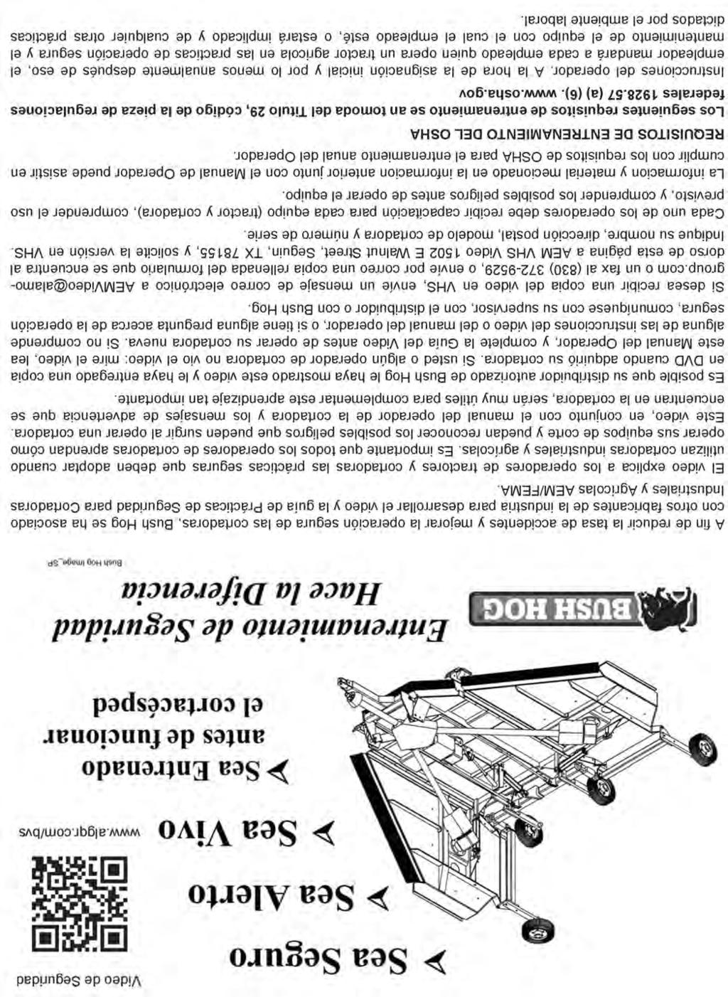
36 SAFETY Federal Laws and Regulations This section is intended to explain in broad terms the concept and effect of federal laws and regulations concerning employer and employee equipment operators. This section is not intended as a legal interpretation of the law and should not be considered as such. Employer-Employee Operator Regulations U.S. Public Law (The Williams-Steiger Occupational and Health Act of 1970) OSHA This Act Seeks:...to assure so far as possible every working man and woman in the nation safe and healthful working conditions and to preserve our human resources... SAFETY DUTIES Sec. 5 (a) Each employer- (1) shall furnish to each of his employees employment and a place of employment which are free from recognized hazards that are causing or are likely to cause death or serious physical harm to his employees; (2) shall comply with occupational safety and health standards promulgated under this Act. (b) Each employee shall comply with occupational safety and health standards and all rules, regulations and orders issued pursuant to this Act which are applicable to his own actions and conduct. OSHA Training Requirements Title 29, Code of Federal Regulations Part (a)(6). Operator instructions. At the time of initial assignment and at least annually thereafter, the employer shall instruct every employee who operates an agricultural tractor and implements in the safe operating practices and servicing of equipment with which they are or will be involved, and of any other practices dictated by the work environment. Keep all guards in place when the machine is in operation; Permit no riders on equipment Stop engine, disconnect the power source, and wait for all machine movement to stop before servicing, adjusting, cleaning or unclogging the equipment, except where the machine must be running to be properly serviced or maintained, in which case the employer shall instruct employees as to all steps and procedures which are necessary to safely service or maintain the equipment. Make sure everyone is clear of machinery before starting the engine, engaging power, or operating the machine. Employer Responsibilities: To ensure employee safety during Tractor and Implement operation, it is the employer s responsibility to: 1. Train the employee in the proper and safe operation of the Tractor and Implement. 2. Require that the employee read and fully understand the Tractor and Implement Operator s manual. 3. Permit only qualified and properly trained employees to operate the Tractor and Implement. 4. Maintain the Tractor and Implement in a safe operational condition and maintain all shields and guards on the equipment. 5. Ensure the Tractor is equipped with a functional ROPS and seat belt and require that the employee operator securely fasten the safety belt and operate with the ROPS in the raised position at all times. 6. Forbid the employee operator to carry additional riders on the Tractor or Implement. 7. Provide the required tools to maintain the Tractor and Implement in a good safe working condition and provide the necessary support devices to secure the equipment safely while performing repairs and service. 8. Require that the employee operator stop operation if bystanders or passersby come within 300 feet. Child Labor Under 16 Years of Age Some regulations specify that no one under the age of 16 may operate power machinery. It is your responsibility to know what these regulations are in your own area or situation. (Refer to U.S. Dept. of Labor, Employment Standard Administration, Wage & Home Division, Child Labor Bulletin #102.) 2308 SERIES 10/15 Safety Section 1-26
37 INTRODUCTION SECTION Introduction Section 2-1

38 INTRODUCTION INTRODUCTION 2308 SERIES 10/15 Introduction Section 2-2

39 INTRODUCTION The Bush Hog 2308 Series Rotary Mower is designed for medium duty applications such as weed, grass, corn stalks, and light brush to 1-1/2" diameter. These mowers are multi spindle with two free-swinging blades on each spindle. Free swinging blades reduce the shock of impact when a stationary object is hit. Additional protection is provided by a slip clutch on the gearbox input shaft and a rubber element shaft between gearboxes. A ovalblade holder allows the mower to ride over stumps and similar immovable objects. These Mowers are attached to the tractor using 3- point Cat I & II standard and quick hitches, and pull hitch. Standard equipment includes driveline shields, clutch shields and front and rear discharge shields. EQUIPMENT SPECIFICATIONS MODELS 2308 Lift, 2308 Semi Mount, 2308 Pull INTRODUCTION Cutting Width (All Models) Overall Width (All Models) Overall Length (Lift, Semi Mount) (Pull) Cutting Height...2 to 13 Cutting Capacity (maximum)...1-1/2 Weight (Lbs.) Lift Lbs. Semi Mount Lbs. Pull Lbs. HP Required (PTO) Lift...50HP Semi Mount...40HP Pull...40HP Blade Tip Speed (540 PTO RPM)...16,173 FPM Gearbox Rating (All Models) Center...140HP Outboard...75HP Limited Warranty...5 Year Driveline...Cat. 4 with1 Year Limited Warranty 2308 SERIES 10/15 Introduction Section 2-3
40 INTRODUCTION The 2308 Series is shipped from the factory with the Front and Rear Safety Enclousers assembled to the cutter. The enclousers can be Single Row or Double Row chains on the front or Single Row Chains, Double Row Chains or a Metal Band to the rear. These Enclousers should be maintained in good working order and remain attached to the cutter when operating in conditions may present a Thrown Object Hazard to Humans or Livestock. INTRODUCTION 2308 Lift Model with Twin Beam Tailwheel and Double Row Chain enclosers front and rear Pull Model with Heavy Duty Axle and Single Row Chain enclosers front and rear SERIES 10/15 Introduction Section 2-4
41 INTRODUCTION KEY OPERATION POINTS Cutting performance and distribution are best when cutter is level from side to side and front to rear. In extra heavy material, rear chains will allow better discharge and better distribution than solid rear deflectors or bands. Never operate the Mower below full PTO speed of 540 or 1000 rpm. Corn should be cut at 5 to 6 mph. If full PTO rpm cannot be maintained, use one lower gear. Operating Noise Level/Sound Pressure The sound levels at the operator's ear from the attached machine (rotary cutter) are at least 10 db(a) below the levels from typical Agricultural tractors used to power and transport this machine. Therefore, the Noise emission values given by the OEM of the Agricultural tractor used to power and transport this machine would be valid when this machine is attached to and operated by that Agricultural tractor in all OEM recommended applications. Warranty information In addition to the standard Limited Warranty shown on the facing page, Bush Hog also provides: 1. A FIVE-YEAR (60 months) LIMITED WARRANTY* on GEARBOX components provided they have been properly maintained and have not been subjected to abuse or mis-use except as limited below. INTRODUCTION * WARRANTY LIMITATIONS - GEARBOX A. Warranty is ONE-YEAR (12 MONTHS) for Seals (After one year, seals are considered to be WEARING PARTS and replacement is the users' responsibility.) B. Users' Gearboxes may be rebuilt by Bush Hog or replaced by new or rebuilt Gearboxes at the option of Bush Hog. 2. ONE-YEAR (12 months) LIMITED WARRANTY** on the DRIVELINE components provided they have been properly maintained and have not been subjected to abuse or mis-use. * *WARRANTY LIMITATIONS - DRIVELINE A. Warranty is ONE-YEAR (12 MONTHS) for DRIVELINE SHIELDS except that evidence of wear from contact with other parts on the shield voids this warranty. B. Shield Bearings are wearing parts and are not warrantable. C. Slip-Clutch Disks are wearing parts and are not warrantable. Evidence of burning up Slip Clutch Plates due to improper adjustment will void warranty on Slip Clutch Parts. NOTE - properly maintained specifically includes, but is not limited to: A) Running Gearboxes with the proper amount of the correct lubricant. B) Adjusting Slip Clutches correctly to provide proper protection for Driveline and Gearbox Components. C) Properly lubricate all driveline components as specified. D) Maintaining proper bearing preload on all gearbox shafts SERIES 10/15 Introduction Section 2-5

42 INTRODUCTION INTRODUCTION 2308 SERIES 10/15 Introduction Section 2-6
43 ASSEMBLY SECTION Assembly Section 3-1

44 ASSEMBLY ASSEMBLY DO NOT attempt any assembly while the machine is still attached to the shipping bracket and standing in the vertical position. Serious injury or death could occur from the machine falling over. Assembly must be performed with the machine placed on a hard level surface with the shipping bracket removed SERIES 10/15 Assembly Section 3-2
45 ASSEMBLY NOTICE! The 2308 is shipped WITHOUT OIL in the Gearboxes and must be filled before connecting to the Tractor and placed in operation! USE 85W / 140 GEAR OIL LEFT SIDE GEARBOX VENT PLUG CENTER GEARBOX FILLER PLUG WITH DIPSTICK RIGHT SIDE GEARBOX ASSEMBLY FILLER PLUG WITH DIPSTICK VENT PLUG OIL FILL CHECK PLUG VENT PLUG 2308 SERIES 10/15 Assembly Section 3-3 OIL FILL PROCEDURE DO NOT OVER FILL GEARBOXES. 1. Remove the oil filler plugs on top the Left and Right side Gearboxes 2. Add 3.13 Quarts (3L) of 85W/140 Gear Oil. 3. Check with dipstick on the filler plug. 4. Remove the vent plug from the top of the Center Gearbox and the top check plug from the back of the Center Gearbox. Fill with 2.6 Quarts (2.5L) of 85W/140 Gear Oil until oil runs out the check plug hole. 5. Reinstall the vent plug and the check plug.
46 ASSEMBLY 3 POINT LIFT MODEL ASSEMBLY ASSEMBLY 2308 Lift Model with Twin Beam Tailwheel selection FLEX LINK ASSEMBLY 1. Install (2) bushings between the LH and RH Struts using 3/4 x 2-1/2 capscrews and 3/4 locknuts at each location. 2. Place the LH and RH Flex Yokes together and align the slotted holes. Place a Bushing into the slotted holes. 3. Install the Flex Yokes with Bushing between the Struts so the slanted end is toward the ground and rest atop the bushing previously installed. Align the holes of the struts and the bushing in the yokes. 4. Insert a 3/4 x 2-1/2 Capscrew and fasten with a 3/4 Locknut. 5. Tighten all fasteners. RH Flex Yoke Bushings Between Struts RH Strut LH Strut LH Flex Yoke Bushing into slotted hole Capscrews 3/4 x 2-1/2 and Locknuts 3/ SERIES 10/15 Assembly Section 3-4
47 ASSEMBLY RH Mast 3/4 Locknut Cat I QH Top Bushing 5/8 x 2 Capscrew Strut Bushing 1 Hex Nut 1 Lockwasher 3 POINT LIFT MODEL ASSEMBLY 3/4 Locknut Spacer Bushing Mast Spacer Spacer Bushing 3/4 x 5-1/2 Capscrew 3/4 x 4 Capscrew 5/8 SAE Flatwasher 5/8 SAE Locknut LH Mast ASSEMBLY Drivline Holder 1 x 2-1/2 Capscrew Cat. II Bushing 3 Point Lift and Semi Mount Spacer Bushing 3 Point Lift and Semi Mount Cat. I Hitch Pin 3 Point Lift and Semi Mount 1. Remove the mast from the shipping position and attach the LH and RH Mast to the inside of the inner mount plates using the rear holes. Install the 2 Strut Bushings in the holes of the Mast. Install using the 5/8 x 2 capscrew, 5/8 SAE flatwasher and 5/8 locknut. Make sure the 5/8 flatwasher is installed to the inside against the bushing in order to retain it in the mast. 2. Assemble the mast halves by placing the CAT I Quick Hitch Top Bushing between the mast in the lower hole and install the 3/4 x 4 capscrew and 3/4 locknut. 3. Attach the RH and LH pivot arm halves to the top holes on the mast. Place the mast spacer between the mast and the pivot arms halves to the outside of the mast. Place a spacer bushing in each pivot arm and install a 3/4 x 5-1/2 Capscrew and 3/4 Locknut. 4. Install the Driveline Holder to the right hand inside strut using the hole the shipping stand was bolted to. Use the 1 x 2-1/2 capscrew, 1 lockwasher and 1 hex nut to attach the Driveline Holder SERIES 10/15 Assembly Section 3-5 SEMI MOUNT MODEL ASSEMBLY 1. Semi Mount Models do not require the Mast or Struts and Flex Links used on the 3 Point Lift models. 2. Cat.I Hitch Pins with Cat. II Bushings and Spacer Bushings are shipped installed to the lift points of the cutter. 3. Install the Driveline Holder to the right hand inside strut using the hole the shipping stand was bolted to. Use the 1 x 2-1/2 capscrew, 1 lockwasher and 1 hex nut to attach the Driveline Holder.

48 ASSEMBLY TAILWHEEL INSTALLATION 3 POINT LIFT and SEMI MOUNT MODELS DUAL TAILWHEEL BEAM ASSEMBLY ASSEMBLY 1. Place the height adjusting collar on the tailwheel beam. 2. Attach the height adjusting bracket to the base frame of the machine. Use two each 1/2 x 3-1/4 capscrews, 1/2 locknuts per bracket. 3. Place the tailwheel beam between the mounting lugs on the base frame and secure with 1/2 x 4-1/2 capscrews and 1/2 locknuts. 4. With the tailwheel beam in the slot of the adjusting bracket, slide the adjusting collar to the bracket and install with two 1/2 x 1-1/4 capscrews and1/2 locknuts. 5. Place the tailwheel through the pivot tube of the tailwheel beam and secure with spiral pin. 6 Apply Grease to pivot tube. Height Adjusting Bracket Capscrew 1/2 x4-1/2 Locknut 1/2 Mounting Lugs Tailwheel Beam Height Adjusting Collar Spiral Pin Capscrew 1/2 x1-1/2 Locknut 1/2 Capscrew 1/2 x3-1/4 Locknut 1/2 Tailwheel Assembly 2308 SERIES 10/15 Assembly Section 3-6
49 ASSEMBLY PULL MODEL ASSEMBLY ASSEMBLY PULL MODEL ASSEMBLY (Refer to Illustration on next page) 1. Remove Tongue assembly from shipping position and assemble to lower front holes of the hitch plates (NOTE: be sure the pivot bushings remain inside the pivot tubes of the tongue.) Install the 1 x 8 capscrews through the tongue pivot tubes and secure with 1 locknuts. 2. Install the Leveling Rods to the tongue with the clevis that has the slotted holes. Place a 1 flatwasher to each side against the slotted hole and insert the clevis pin. Secure with the 3/16 x 1-1/2 Cotter Pins. 3. Attach the Leveling Rods to the Axle Lugs with the Clevis Pin and two 3/16 x 1-1/2 Cotter Pins. 4. Place the Axle Arm assemblies to the Axle assembly and secure with (2) U-bolts per Axle Arm and (2) 3/4 Hex Nuts, 3/4 Lockwashers, 3/4 Flatwashers per U - Bolt. 5. Remove the Lug Nuts along with the Hub Cap Retainer. Install the Wheel assembly. Replace Hub Cap Retainer on one of the lug bolts. Install the Lug Nuts and tighten. 6. Hose Holder is placed atop the hole in the plate between the Hitch Plates. Place a 1/2 Flatwasher on top of the mounting loop of the Hose Holder and insert a 1/2 x1-1/2 Capscrew through the assembly securing with a 1/2 Locknut to the underside of the plate SERIES 10/15 Assembly Section 3-7
50 ASSEMBLY PULL MODEL ASSEMBLY Step 3 Steps 1 & 2 Step 4 ASSEMBLY Steps 5 Step SERIES 10/15 Assembly Section 3-8


51 ASSEMBLY TIRES AND WHEELS Before installing any tires and wheels make certain the Cutter is jacked up high enough and is securely supported. When installing laminated or airplane tires, be sure the flat side of the lug nut is against the wheel. There are only three types of tires that can be used on this cutter DO NOT USE ANY OTHER TYPE OF TIRE OR WHEEL, such as automutive tires and rims. DO NOT EXCEED THE MAXIMUM SPEED FOR EACH TYPE OF TIRE. Excessive speed can cause damage to the machine, tire and wheel. When installing Laminated Tires and Wheels note the direction of travel and curvature of rubber segments of the tire and install as shown in illustration below. Do not exceed 20 M.P.H. on Lamianted Tires. Before seperating wheel halves on Airplane Tires,let all the air out ouf the tire by removing the valve core to make certain no air pressure is left in the tube befor seperating the wheel halves to dismount tire. *DO NOT LOOSEN WHEEL CLAMP BOLTS BEFORE PRESSURE IS REMOVED FROM TUBE AND TIRE TO PREVENT EXPLOSIVE SEPERATION OF WHEEL HALVES WITH POSSIBLE SERIOUS BODILY IN- JURY. NOTE SEGMENT CURVATURE Place Flatside of Lug Nut Against Wheel ASSEMBLY LAMINATED TIRE Place Flatside of Lug Nut Against Wheel *Wheel Clamp Bolts Lugnuts FOAM FILLED TIRE MAXIMUM INFLATION PRESSURE 40 PSI MAXIMUM SPEED 20 MPH *Wheel Clamp Bolts Lugnuts AIRPLANE TIRE 2308 SERIES 10/15 Assembly Section 3-9

52 ASSEMBLY AXLE HEIGHT CONTROL 2308 Models Axle Working Height is determined by either a mechanical Ratchet Assembly or a single acting Hydraulic Cylinder using Stop Collar adjustments. HYDRAULIC KIT INSTALLATION ASSEMBLY 1. Install the Hydraulic Cylinder to the machine with the Rod End of the cylinder to the cylinder lug on the axle and the Base End of the cylinder to the mount lug on the base frame. 2. Remove the plug on the Rod End of the cylinder and replace with the Breather Plug supplied. 3. Remove the plug at the base end of the cylinder and install the Hydraulic Adaptor 9/16 JIC x 3/4 SAE with O ring in the cylinder. 4. Attach the Hydraulic Hose to the adaptor. 5. There are two adaptors furnished in the kit to adapt the hose to the fitting used in the hydraulic port on the tractor. Determine which adaptor is required for your application and install to the hydraulic hose. 6. Attach the fitting for the tractor hydraulic port to the hose. 7. Make sure all fittings at tight and plug in hose to tractor hydraulic port. DO NOT ATTEMPT TO CHARGE THE HYDRAULIC CYLINDER WITHOUT THE BREATHER PLUG INSTALLED. DAMAGE TO THE CYLINDER MAY OCCUR. 8. Crank the tractor and from the drivers seat cycle the cylinder several times. 9. Extend the Cylinder Rod and install the Stop Collars to support the machine. Hydraulic Adaptor 9/16 JIC to3/4 SAE with O Ring Breather Plug Cylinder Rod End Cylinder Base End Stop Collar Kit RATCHET INSTALLATION 1. Remove the Clevis Pins from the Ratchet Assembly and place the clevis ends to the Axle Lug and the Mount Lug on the Base Frame. 2. Install the Clevis Pins 2308 SERIES 10/15 Assembly Section 3-10
53 ASSEMBLY DRIVELNE ATTACHMENT DRIVELINE ATTACHMENT - SLIP CLUTCH Before starting assembly, make certain that all paint, dirt and grease are removed from gearbox shaft. To ease assembly, apply a light coat of grease to splines, then assemble. Do not assemble a driveline without a shield. Entanglement in rotating shafts can kill. ASSEMBLY 1. Remove tapered pin from splined clutch hub on the end of the driveshaft. 2. Open the clutch shield inspection holes to expose the gearbox input shaft and give access to theyoke. 3. Slide the Slip Clutch end of the driveline onto the gearbox input shaft. 4. Make certain that the slip clutch is fully onto the input shaft splines. 5. Align the tapered pin hole in the hub with the grove on the input shaft. 6. Install the tapered pin, washer and locknut. Torque the nut to 30 ft./lbs SERIES 10/15 Assembly Section 3-11
54
55 OPERATION SECTION Operation Section 4-1

56 OPERATION BUSH HOG 2308 SERIES ROTARY WOWER OPERATION INSTRUCTIONS OPERATION 2308 SERIES 10/15 Operation Section 4-2

57 OPERATION OPERATION 2308 SERIES 10/15 Operation Section 4-3
58 OPERATION OPERATION Tractor Requirements and Capabilities ASABE approved Roll-Over Protective Structure (ROPS) or ROPS cab and seat belt. Tractor Safety Devices... Slow Moving Vehicle (SMV) emblem, lighting, PTO master shield Tractor Horsepower: -Minimum... Lift - 50 HP, Pull - 40 HP & Semi-Mount - 40 HP -Maximum HP Hitch -Lift Type Mower: - Lifting Capacity... Lift lbs, Semi-Mount lbs - 3-Point Hitch CAT I-II and Quick Hitch, CAT I-II Semi-Mount, center pull -Hydraulics... Optional Pull Type Mower: -Drawbar extended length, safety chain attachment point -Hydraulics... Optional Front End Weight... As needed to maintain 20% weight on front axle Power Take Off RPM 6-spline, 1-3/8 diameter output shaft 2308 SERIES 10/15 Operation Section 4-4
 emblem which are clearly visible from the rear of the unit. Lights and a SMV emblem must be equipped directly on implements if the visibility of the tractor warning signals are obscured.")
59 OPERATION Tractor Safety Devices If transporting or operating the tractor and implement near a public roadway, the tractor must be equipped with proper warning lighting and a Slow Moving Vehicle (SMV) emblem which are clearly visible from the rear of the unit. Lights and a SMV emblem must be equipped directly on implements if the visibility of the tractor warning signals are obscured. Maintain all manufacturer equipped safety shields and guards. Always replace shields and guards that were removed for access to connect, service, or repair the tractor or implement. Never operate the tractor PTO with the PTO master shield missing or in the raised position. OPS-U Tractor Horsepower The power required to operate a mower is determined by the tractor PTO horsepower. For most mowing conditions, the 2308 Series lift mower requires a tractor with at least 50 HP and the semi-mount and pull type mower require at least 40 HP. Operating the mower with a tractor that does not have adequate power may damage the tractor engine. Exceeding 75 HP may cause mower damage by overpowering the unit in heavy cutting conditions. 3-Point Hitch Lift Type Mower-The tractor 3-point hitch must be rated to lift at least 1850 lbs. The Model 2308 Series is designed to be mounted on a tractor with CAT I or CAT II 3-point or CAT I or CAT II Quick Hitch. Top Link attaches here OPERATION Refer to the tractor operator s manual for the category of the tractor being used. If the hitch does not conform to ASABE dimensions, the mower may not fit or raise properly. Consult an authorized dealer for possible modification procedures to mount non-conforming hitches. Depending on the hitch category, certain size pins are used to attach the mower to the tractor. Quick Hitch requires 1-7/16 diameter lower pin and 1-1/4 diameter upper pin. CAT II hitches require 1-1/8 lower pins and 1 inch upper pins. CAT III hitches require 1-7/16 lower pins and 1-1/4 upper pin diameters. Our 3-point Quick Hitch is designed to connect to a Quick-Attach coupler making mounting and dismounting your mower easier. The 3-Point Quick Hitch is also designed to connect the mower to a tractor s 3-point linkage without the use of a Quick Attach Coupler. Lift Arms attach here 2308 SERIES 10/15 Operation Section 4-5
 2308 SERIES 10/15 Operation")
60 OPERATION Drawbar - Pull Type Mower OPERATION Front End Weight Power Take Off (PTO) 2308 SERIES 10/15 Operation Section 4-6

61 OPERATION OPERATION 2308 SERIES 10/15 Operation Section 4-7

62 OPERATION OPERATION 2308 SERIES 10/15 Operation Section 4-8
63 OPERATION OPERATION 2308 SERIES 10/15 Operation Section 4-9

64 OPERATION OPERATION 2308 SERIES 10/15 Operation Section 4-10

65 OPERATION OPERATION 2308 SERIES 10/15 Operation Section 4-11

66 OPERATION OPERATION 2308 SERIES 10/15 Operation Section 4-12

67 OPERATION OPERATION 2308 SERIES 10/15 Operation Section 4-13

 If a hydraulic cylinder is used for height control, stroke spacers can be placed on the cylinder rod to maintain a set cutting height. 2.")
68 OPERATION OPERATION Setting Mowing Height - Pull Type 1. Park the tractor and mower on level ground. 2. Using the hydraulic cylinder or ratchet attached to the rear axle position the front skid shoes 1 less off the ground of the desired mowing height. (Example: If a 3 cut is desired Place the Skidshoes at 2 off the ground.) If a hydraulic cylinder is used for height control, stroke spacers can be placed on the cylinder rod to maintain a set cutting height. 2. Adjust the two Leveling Rods so the front of the mower is approximately 3/4 lower than the rear. 3. Level Rod adjustment is achieved by loosening the lock nut against the clevis and screwing the Level Rods in or out to set desired setting. 4. Be sure Level rods are equally set to maintain a level cut. 5. Tighten the Lock Nut against the clevis to maintain the setting. Leveling Rod Lock Nut Clevis 2308 SERIES 10/15 Operation Section 4-14

69 OPERATION OPERATION 2308 SERIES 10/15 Operation Section 4-15

70 OPERATION OPERATION 2308 SERIES 10/15 Operatio Section 4-16

71 Constant Velocity (CV) Driveline OPERATION OPERATION 2308 SERIES 10/15 Operation Section 4-17

72 OPERATION OPERATION 2308 SERIES 10/15 Operation Section 4-18

73 OPERATION OPERATION 2308 SERIES 10/15 Operation Section 4-19

74 OPERATION OPERATION 2308 SERIES 10/15 Operation Section 4-20

75 OPERATION OPERATION 2308 SERIES 10/15 Operation Section 4-21

76 OPERATION OPERATION 2308 SERIES 10/15 Operation Section 4-22
77 OPERATION OPERATION Check Output Shaft Nut Torque Maintain at 450 ft. lbs. Check Blade Bolt Torque Maintain at 600 ft. lbs SERIES 10/15 Operation Section 4-23

78 OPERATION OPERATION 2308 SERIES 10/15 Operation Section 4-24
79 OPERATION OPERATION 2308 SERIES 10/15 Operation Section 4-25
80 OPERATION OPERATION 2308 SERIES 10/15 Operation Section 4-26

81 OPERATION OPERATION 2308 SERIES 10/15 Operation Section 4-27

82 OPERATION OPERATION 2308 SERIES 10/15 Operation Section 4-28

83 OPERATION OPERATION 2308 SERIES 10/15 Operation Section 4-29

84 OPERATION OPERATION 2308 SERIES 10/15 Operation Section 4-30

85 OPERATION OPERATION 2308 SERIES 10/15 Operation Section 4-31

86 OPERATION OPERATION 2308 SERIES 10/15 Operation Section 4-32

87 OPERATION OPERATION 2308 SERIES 10/15 Operation Section 4-33

88 OPERATION OPERATION 2308 SERIES 10/15 Operation Section 4-34

89 OPERATION OPERATION 2308 SERIES 10/15 Operation Section 4-35

90 OPERATION OPERATION 2308 SERIES 10/15 Operation Section 4-36

91 OPERATION OPERATION 2308 SERIES 10/15 Operation Section 4-37

92 OPERATION OPERATION 2308 SERIES 10/15 Operation Section 4-38

93 OPERATION OPERATION 2308 SERIES 10/15 Operation Section 4-39

94 OPERATION OPERATION 2308 SERIES 10/15 Operation Section 4-40

95 OPERATION OPERATION 2308 SERIES 10/15 Operation Section 4-41

96 OPERATION OPERATION 2308 SERIES 10/15 Operation Section 4-42

97 OPERATION OPERATION 2308 SERIES 10/15 Operation Section 4-43

98 OPERATION OPERATION 2308 SERIES 10/15 Operation Section 4-44
99 OPERATION OPERATION 2308 SERIES 10/15 Operation Section 4-45
100 OPERATION OPERATION 2308 SERIES 10/15 Operation Section 4-46
101 MAINTENANCE SECTION Maintenance Section 5-1

102 MAINTENANCE MAINTENANCE 2308 SERIES 10/15 Maintenance Section 5-2
103 MAINTENANCE MAINTENANCE 2308 SERIES 10/15 Maintenance Section 5-3

104 MAINTENANCE 3 POINT LIFT and SEMI MOUNT GREASE POINTS Gearboxes MAINTENANCE Caster Spindles Wheel Hubs 2308 SERIES 10/15 Maintenance Section 5-4
105 MAINTENANCE PULL HITCH GREASE POINTS Gearboxes MAINTENANCE Wheel Hubs 2308 SERIES 10/15 Maintenance Section 5-5

106 MAINTENANCE GEARBOX The gearboxes should not require additional lubricant unless the box is cracked or a seal is leaking. It is recommended that the oil level be checked after 8 to 10 hours of operation. If additional oil is required follow the steps below under OIL FILL PROCEDURE. MAINTENANCE Use 85W/140 Gear Oil. Under no circumstances should the fill level exceed the fill level marks on the dipsticks on the outboard boxes or past the Oil Fill Check Plug on the rear of the Center Gearbox. NOTE: Overfilling the Gearboxes can cause a buildup of pressure during operation and blow out the seals and cause the excess oil to spew from the Vent Plugs! ATTENTION: If Gearbox suddenly starts making an unusual noise, stop at once, check for leaks and refill Gearbox as required. LEFT SIDE GEARBOX VENT PLUG CENTER GEARBOX FILLER PLUG WITH DIPSTICK RIGHT SIDE GEARBOX FILLER PLUG WITH DIPSTICK VENT PLUG OIL FILL CHECK PLUG OIL FILL PROCEDURE DO NOT OVER FILL GEARBOXES! VENT PLUG 1. Remove the oil filler plugs on top the Left and Right side Gearboxes 2. Add additional oil (as needed) of 85W/140 Gear Oil. 3. Check with dipstick on the filler plug. 4. Remove the vent plug from the top of the Center Gearbox and the top Oil Fill Check Plug from the back of the Center Gearbox. Fill with additional oil (as needed) of 85/140 Gear Oil until oil runs out the Oil Fill Check Plug hole. 5. Reinstall the vent plug and the check plug SERIES 10/15 Maintenance Section 5-6


107 MAINTENANCE MAINTENANCE 2308 SERIES 10/15 Maintenance Section 5-7

108 MAINTENANCE MAINTENANCE 2308 SERIES 10/15 Maintenance Section 5-8
109 MAINTENANCE MAINTENANCE 2308 SERIES 10/15 Maintenance Section 5-9
110 MAINTENANCE MAINTENANCE 2308 SERIES 10/15 Maintenance Section 5-10
111 MAINTENANCE MAINTENANCE 2308 SERIES 10/15 Maintenance Section 5-11
112 MAINTENANCE MAINTENANCE 2308 SERIES 10/15 Maintenance Section 5-12
113 MAINTENANCE MAINTENANCE 2308 SERIES 10/15 Maintenance Section 5-13
114 MAINTENANCE MAINTENANCE 2308 SERIES 10/15 Maintenance Section 5-14

115 MAINTENANCE MAINTENANCE 2308 SERIES 10/15 Maintenance Section 5-15

116 MAINTENANCE MAINTENANCE 2308 SERIES 10/15 Maintenance Section 5-16
117

118 SAFETY 2308 SERIES 10/15 Sección de Seguridad 1-25 SEGURIDAD

119 SAFETY 2308 SERIES 10/15 Sección de Seguridad 1-24 SEGURIDAD

120 SAFETY 2308 SERIES 10/15 Sección de Seguridad 1-23 SEGURIDAD

121 SAFETY 2308 SERIES 10/15 Sección de Seguridad 1-22 SEGURIDAD

122 SAFETY 2308 SERIES 10/15 Sección de Seguridad 1-21 SEGURIDAD

123 SAFETY 2308 SERIES 10/15 Sección de Seguridad 1-20 SEGURIDAD

124 SAFETY 2308 SERIES 10/15 Sección de Seguridad 1-19 SEGURIDAD

125 SAFETY 2308 SERIES 10/15 Sección de Seguridad 1-18 SEGURIDAD

126 SAFETY 2308 SERIES 10/15 Sección de Seguridad 1-17 SEGURIDAD

127 SAFETY 2308 SERIES 10/15 Sección de Seguridad 1-16 SEGURIDAD

128 SAFETY 2308 SERIES 10/15 Sección de Seguridad 1-15 SEGURIDAD
129 SAFETY 2308 SERIES 10/15 Sección de Seguridad 1-14 SEGURIDAD

130 SAFETY 2308 SERIES 10/15 Sección de Seguridad 1-13 SEGURIDAD

131 SAFETY 2308 SERIES 10/15 Sección de Seguridad 1-12 SEGURIDAD

132 SAFETY 2308 SERIES 10/15 Sección de Seguridad 1-11 SEGURIDAD

133 SAFETY 2308 SERIES 10/15 Sección de Seguridad 1-10 SEGURIDAD

134 SAFETY 2308 SERIES 10/15 Sección de Seguridad 1-9 SEGURIDAD

135 SAFETY 2308 SERIES 10/15 Sección de Seguridad 1-8 SEGURIDAD

136 SAFETY 2308 SERIES 10/15 Sección de Seguridad 1-7 SEGURIDAD

137 SAFETY 2308 SERIES 10/15 Sección de Seguridad 1-6 SEGURIDAD

138 SAFETY 2308 SERIES 10/15 Sección de Seguridad 1-5 SEGURIDAD

139 SAFETY 2308 SERIES 10/15 Sección de Seguridad 1-4 SEGURIDAD

140 SAFETY 2308 SERIES 10/15 Sección de Seguridad 1-3 SEGURIDAD

141 SAFETY 2308 SERIES 10/15 Sección de Seguridad 1-2 SEGURIDAD
142 2308 SERIES 10/15 Sección de Seguridad 1-1
143

144
145
146

147 Placa de Número de serie


148 2308 SERIES Modelo 2308 Publicado en 10/15 Parte no
4815RR1,4810RR RR1,14810RR1
 4815RR1,4810RR1 14815RR1,14810RR1 This Manual applies to Models: 4815RR1, 4810RR1, 14815RR1, 14810RR1 FLEX-WING ROTARY CUTTERS / SHREDDERS Published 07/16 Part No. 50076491 To the Owner/Operator/Dealer
320 Series Models 325, 326, 327
 0 Series Models,, ROTARY MOWER Published 0/ PARTS MANUAL SECTION An Operator s Manual was shipped with the equipment. The Operator s Manual is an integral part of the safe operation of this machine and
PARTS MANUAL SECTION. Models 295, 296, 297, 1297 ROTARY MOWER
 0 Series Models,,, ROTARY MOWER Published 0/ PARTS MANUAL SECTION An Operator s Manual was shipped with the equipment. The Operator s Manual is an integral part of the safe operation of this machine and
BUSH HOG LAND MAINTENANCE REPAIR PARTS MANUAL MODEL: 3414 SECTION: 67
 BUSH HOG LAND MAINTENANCE REPAIR S MANUAL MODEL: SECTION: 0 Griffin Ave. Selma, AL 0 () - () -00 Parts Ordering -00-0- Fax -00-- www.bushhog.com BUSH HOG/ LAND MAINTENANCE REPAIR S MANUAL July, 0 ROTARY
2720/12720 PARTS MANUAL 72A SECTION FLEX WING ROTARY MOWER
 0/0 This Manual applies to models 0 and 0 that use a blade pan which measures. blade hole center to blade hole center. Also blades measure 8. from hole center to blade tip. See Section if these dimensions
SECTION V ASSEMBLY CAUTION THE FOLLOWING SAFETY PRECAUTIONS SHOULD BE THOROUGHLY UNDERSTOOD BEFORE ATTEMPTING MACHINE ASSEMBLY.
 SECTION V ASSEMBLY CAUTION THE FOLLOWING SAFETY PRECAUTIONS SHOULD BE THOROUGHLY UNDERSTOOD BEFORE ATTEMPTING MACHINE ASSEMBLY. 1. Wear personal protective equipment such as, but not limited to protection
Part Number Published 08/ Series Blade. 181 Series Blade
 141 SERIES 181 SERIES Published 08/15 Part Number 50076192 141 Series Blade 181 Series Blade To the Owner/Operator/Dealer All implements with moving parts are potentially hazardous. There is no substitute
BH200 SERIES ROTARY CUTTER
 Revised Published01/19 BH200 SERIES ROTARY CUTTER PARTS MANUAL SECTION 121 MODELS BH215, BH216, BH217 An Operator s Manual was shipped with the equipment. The Operator s Manual is an integral part of the
SQ84T SQUEALER. Dual Spindle Offset Lift Type Rotary Mower Published 01/19 Part No Alamo Group Inc.
 SQ84T SQUEALER Dual Spindle Offset Lift Type Rotary Mower Published 01/19 Part No. 50075492 This Operator's Manual is an integral part of the safe operation of this machine and must be maintained with
LAND MAINTENANCE REPAIR PARTS MANUAL BUSH HOG MODEL: 307 SECTION: 16
 BUSH HOG LAND MAINTENANCE REPAIR S MANUAL MODEL: 0 SECTION: P.O. Box 0 Selma, AL 0-0 () - () -00 Parts Ordering -00-0- Fax -00-- www.bushhog.com BUSH HOG / LAND MAINTENANCE REPAIR S MANUAL SEPTEMBER, 0
SUNDOWN Operation. & Parts Manual. for Box Blade Models BB15-48, 60 BB20-48, 60, 72 BB30-60, 72, 84, & 96
 SUNDOWN Operation & Parts Manual for Box Blade Models BB15-48, 60 BB20-48, 60, 72 BB30-60, 72, 84, & 96 Operations and Parts Manual Table of Contents Section Page Table of Contents 2 Retail Customer Responsibility
BUSH HOG LAND MAINTENANCE REPAIR PARTS MANUAL MODEL: 280 SERIES SECTION: 59
 BUSH HOG LAND MAINTENANCE REPAIR S MANUAL MODEL: 0 SERIES SECTION: P.O. Box 0 Selma, AL 0-0 () - () -00 Parts Ordering -00-0- Fax -00-- www.bushhog.com BUSH HOG/ LAND MAINTENANCE REPAIR S MANUAL JUNE,
BUSH HOG LAND MAINTENANCE REPAIR PARTS MANUAL MODEL: 405 / 406 SECTION: 17
 BUSH HOG LAND MAINTENANCE REPAIR S MANUAL MODEL: 0 / 0 SECTION: 0 Griffin Ave. Selma, AL 0 () - () -00 Parts Ordering -00-0- Fax -00-- www.bushhog.com BUSH HOG/ LAND MAINTENANCE REPAIR S MANUAL SEPTEMBER,
BUSH HOG LAND MAINTENANCE REPAIR PARTS MANUAL MODEL: 280 SERIES SECTION: 59
 BUSH HOG LAND MAINTENANCE REPAIR S MANUAL MODEL: 0 SERIES SECTION: 0 Griffin Ave. Selma, AL 0 () () 00 Parts Ordering 00 0 Fax 00 www.bushhog.com BUSH HOG/ LAND MAINTENANCE REPAIR S MANUAL October, 0 0
3308, 3308SH PARTS MANUAL SECTION ROTARY MOWER
 0, 0SH ROTARY MOWER Published / PARTS MANUAL SECTION 0 An Operator s Manual was shipped with the equipment. The Operator s Manual is an integral part of the safe operation of this machine and must be maintained
ROTARY MOWER OPERATION, SERVICE & PARTS MANUAL FOR
 ROTARY MOWER OPERATION, SERVICE & PARTS MANUAL FOR L-G-40-40-P, L-G-48-40-P, L-G-60-40-P & L-G-72-40-P Slip Clutch Models: L-G-60-40-SC-P & L-G-72-40-SC-P February 2003 FORM: RotMwrBook.QXD TABLE OF CONTENTS
Bush Hog Land Maintenance Parts May, 2017
 Revised 05/17 Bush Hog Land Maintenance Parts May, 2017 TABLE OF CONTENTS ROTARY CUTTERS BH4-2, BH5-2, BH6-2 DESCRIPTION...PAGE NUMBER Tail Wheel Assembly (With Hub)...104A-1-1 Tail Wheel Assembly (Without
BOX SCRAPERS. Operation, Service & Parts Manual For Models: BB30-60, BB30-66, BB30-72, & BB FORM: BB30Scraper.QXD
 BOX SCRAPERS Operation, Service & Parts Manual For Models: BB30-60, BB30-66, BB30-72, & BB30-84 FORM: BB30Scraper.QXD September 2006 TABLE OF CONTENTS Introduction.............................1 Safety
PARTS MANUAL 3510, 3510-O, SECTION ROTARY MOWER
 , -O, ROTARY MOWER Published 0/ S MANUAL SECTION An Operator s Manual was shipped with the equipment. The Operator s Manual is an integral part of the safe operation of this machine and must be maintained
BUSH HOG LAND MAINTENANCE REPAIR PARTS MANUAL MODELS: RPM & RPM SECTION: 79
 BUSH HOG LAND MAINTENANCE REPAIR S MANUAL MODELS: -0 RPM & -000 RPM SECTION: 9 0 Griffin Ave. Selma, Al. 0 () - () -00 Parts Ordering -00-0- Fax -00-- www.bushhog.com April, 0 BUSH HOG/ LAND MAINTENANCE
PARTS MANUAL SECTION 105 FLEX WING ROTARY CUTTER. Published 09/14
 8 FLEX WING ROTARY CUTTER Published 09/ PARTS MANUAL SECTION 0 An Operator s Manual was shipped with the equipment. The Operator s Manual is an integral part of the safe operation of this machine and must
MULTI-SPINDLE ROTARY CUTTERS
 Performance You Can Count On MULTI-SPINDLE ROTARY CUTTERS SQ & 2000 SERIES 3000 SERIES Nothing beats a Bush Hog! Bush Hog s entire line of multi-spindle rotary cutters is designed for heavy crop clearing,
MULTI-SPINDLE ROTARY CUTTERS
 MULTI-SPINDLE ROTARY CUTTERS SQ & 2000 Series MULTI-SPINDLE ROTARY CUTTERS Nothing beats a Bush Hog! Bush Hog s entire line of multi-spindle rotary cutters is designed for heavy crop clearing, pasture
LANDSCAPE RAKE. Operation & Parts Manual For 20 Series LR20-60 & LR April Form: MW_LandscapeRakes
 LANDSCAPE RAKE Operation & Parts Manual For 20 Series LR20-60 & LR20-72 April 2008 Form: MW_LandscapeRakes TABLE OF CONTENTS PAGE Introduction...1 Checklists...2 General Informatioon...3 Safety Rules...4
Pre-Delivery Checklist
 Pre-Delivery Checklist The Dealer should inform the Purchaser of this product of the Warranty terms, provisions, and procedures that are applicable. The Dealer and Purchaser should review the contents
Pre-Delivery Checklist
 Pre-Delivery Checklist The Dealer should inform the Purchaser of this product of the Warranty terms, provisions, and procedures that are applicable. The Dealer and Purchaser should review the contents
Mulching and Finishing Mowers MP and FP
 Mulching and Finishing Mowers MP and FP Parts Manual Locke Turf 0 Highway E, Opp, Alabama, () -00 Transport Wheel, Tire & Spindle MP and FP ALPHABETICAL INDEX CONTENTS PAGE 00 Hydraulic Cylinder (Rear)
Performance You Can Count On FLEX-WING ROTARY CUTTERS
 Performance You Can Count On FLEX-WING ROTARY CUTTERS 1812 1815 2215 2810 2815 3810 3815 4815 2820 1812 FLEX-WING ROTARY CUTTER The 1812 Flex-Wing Rotary Cutter is designed for small tractors with a PTO
BUSH HOG LAND MAINTENANCE REPAIR PARTS MANUAL MODEL: TD-1100 SECTION: 66
 BUSH HOG LAND MAINTENANCE REPAIR S MANUAL MODEL: TD-00 SECTION: 0 Griffin Ave. Selma, AL 0 () - () -00 Parts Ordering -00-0- Fax -00-- www.bushhog.com BUSH HOG/ LAND MAINTENANCE REPAIR S MANUAL JUNE, 00
Rotary Cutters RCR3596, RCRM3596, RCR3510 & RCRM3510
 Rotary Cutters RCR3596, RCRM3596, RCR3510 & RCRM3510 15998! Read the Operator s Manual entirely. When you see this symbol, the subsequent instructions and warnings are serious - follow without exception.
GROUNDSMASTER. 52 Recycler. for 120 Traction Unit. Model No & UP. Operator s Manual
 FORM NO. 8-980 Rev A GROUNDSMASTER 5 Recycler for 0 Traction Unit Model No. 077 79000 & UP Operator s Manual IMPORTANT: Read this manual carefully. It contains information about your safety and the safety
BUSH HOG LAND MAINTENANCE REPAIR PARTS MANUAL MODEL: RZ60 SECTION: 31
 BUSH HOG LAND MAINTENANCE REPAIR S MANUAL MODEL: RZ0 SECTION: 0 Griffin Ave. Selma, AL 0 (4) - (4) 4-00 Parts Ordering -00-04- Fax -00--4 www.bushhog.com BUSH HOG/ LAND MAINTENANCE REPAIR S MANUAL JANUARY
AG84-B ARCHIVE BOOK ROTARY MOWER. By Serial Number / Production COMPLETE PARTS LISTING. ALAMO INDUSTRIAL 1502 E. Walnut
 AG8-B ROTARY MOWER ARCHIVE BOOK By Serial Number / Production April 99 May 00 () AG8-B Model - 8" Rotary Pull Type or Lift Type Option COMPLETE PARTS LISTING Archive Book Part No. 0979 ALAMO INDUSTRIAL
ProLine. 44 Mower. for 120 Traction Unit. Model No & Up. Operator s Manual
 FORM NO. 9 ProLine Mower for 0 Traction Unit Model No. 05 99000 & Up Operator s Manual IMPORTANT: Read this manual carefully. It contains information about your safety and the safety of others. Also become
PARTSBOOK. This part of the manual contains part numbers and illustrations based on the latest information available at the time of print.
 2 PARTSBOOK This part of the manual contains part numbers and illustrations based on the latest information available at the time of print. Hall Manufacturing, Inc. reserves the right to make changes at
2820/12820 SECTION 103. This Manual applies to Models: 2820R1, 12820R1, 12820S1 2820RR1, 12820RR1, 12820SR1 FLEX WING ROTARY CUTTER/SHREDDER
 0/0 This Manual applies to Models: 0R, 0R, 0S 0RR, 0RR, 0SR FLEX WING ROTARY CUTTER/SHREDDER Published 0/ PARTS MANUAL SECTION 0 An Operator s Manual was shipped with the equipment. The Operator s Manual
PARTS MANUAL SECTION R1, 2215RR1-540 RPM 12215R1, 12215RR1-1000RPM FLEX WING ROTARY CUTTER. Published 07/16
 225R, 225RR - 50 RPM 225R, 225RR - 000RPM FLEX WING ROTARY CUTTER Published 07/6 PARTS MANUAL SECTION 3 An Operator s Manual was shipped with the equipment. The Operator s Manual is an integral part of
EverythingAttachments.com
 EverythingAttachments.com 60 Xtreme Duty Brush Cutter Owner s Manual SAFETY GENERAL SAFETY INSTRUCTIONS AND PRACTICES A careful operator is the best operator. Safety is of primary importance to the manufacturer
Operator s Manual. Table of Contents. Rotary Cutter RC35120 RCM Copyright 2008 Printed M 7/14/08
 Operator s Manual RC35120 RCM35120 Rotary Cutter 10438 Cover photo may show optional equipment not supplied with standard unit.! Read the Operator s manual entirely. When you see this symbol, the subsequent
AERATORS. Operation & Parts Manual For 20 Series AE20-48, AE20-60, & AE April Form: MW_Aerators
 AERATORS Operation & Parts Manual For 20 Series AE20-48, AE20-60, & AE20-72 April 2008 Form: MW_Aerators TABLE OF CONTENTS PAGE Introduction...1 Checklists...2 General Information...3 Safety Rules...4
HT419H BUSH HOG. 2501Griffin Ave. Selma, Al Published 11/15 Part No
 Published Part No. 50076695 BUSH HOG 2501Griffin Ave. Selma, Al 36703 www.bushhog.com Read and understand the complete Warranty Statement Found in this Manual. Be sure at time of purchase your Dealer has
SINGLE SPINDLE ROTARY CUTTERS
 SINGLE SPINDLE ROTARY CUTTERS RAZORBACK-SERIES ROTARY CUTTER AVAILABLE IN RED, ORANGE, BLUE, AND GREEN The Razorback-Series has Bush Hog s legendary durability and reliability built into each of the three
FLX15 ROTARY CUTTERS PARTS MANUAL ATENCIÓN! LEA EL INSTRUCTIVO
 Published: /0 FLX ROTARY CUTTERS S/N A00000 A0000 inclusive PARTS MANUAL Part No. A0-00P An Operators Manual with IMPORTANT Safety, Assembly, Operation and Maintenance information was packaged with this
TT4101 Rotary Tedder
 TT Rotary Tedder 0//0 Illustrated Parts Breakdown Page Page Page Page Page Page Page Page Page Page Page Tongue Assembly S/N S/N - Tongue Assembly S/N + Main Frame S/N - Main Frame S/N to Main Frame S/N
BUSH HOG. Operator s Manual FLEX-WING ROTARY CUTTER ASSEMBLY OPERATION MAINTENANCE. Part No
 BUSH HOG 2315 FLEX-WING ROTARY CUTTER Operator s Manual ASSEMBLY OPERATION MAINTENANCE 797 $4.00 Part No. 91885 CONGRATULATIONS! You have invested in the best implement of its type on the market today.
1 RS-300/D 320/D 340/D 350H Parts Manual
 300/D 320/D 340/D 350H Parts Manual Table Of Contents Three Point Hitch / Hitch Frame Assembly... 3 Tongue Pull Hitch Assembly... 7 Main Gearbox... 11 Crank Handle & Gear... 13 Hydraulic Lift... 15 Rotor
ALAMO INDUSTRIAL WARRANTY REGISTRATION INFORMATION
 TEAR TEAR TEAR TEAR TEAR TEAR TEAR TEAR TEAR TEAR TEAR TEAR TEAR TEAR TEAR TEAR TEAR TEAR TEAR TEAR TEAR TEAR TEAR TEAR TEAR 1. PRINT FIRMLY. 2. REMOVE WHITE COPY FOR CUSTOMER RECORDS. 3. REMOVE YELLOW
TT4100 Rotary Tedder
 TT0 Rotary Tedder Serial numbers 0 and higher Illustrated Parts Breakdown Page Page Tongue Assembly S/N - Tongue Assembly S/N to Page Page Page Page Page Tongue Assembly S/N to Tongue Assembly S/N + Main
BUSH HOG. Model 4215 Rotary Cutter Operator s Manual. OPERATION l MAINTENANCE. 05/09 Rev. 1 $
 BUSH HOG Model 4215 Rotary Cutter Operator s Manual OPERATION l MAINTENANCE 05/09 Rev. 1 $4.00 91121 CONGRATULATIONS! You have invested in the best implement of its type on the market today. The care you
BUSH HOG. ASSEMBLY l OPERATION l MAINTENANCE. Model ATH 720 Air Tunnel. Model FTH 600 Flat Tunnel. 04/09 Rev.1 $
 BUSH HOG ATH/FTH Air Tunnel & Flat Deck Finishing Mowers Operator s Manual Model ATH 720 Air Tunnel Model FTH 600 Flat Tunnel ASSEMBLY l OPERATION l MAINTENANCE 04/09 Rev.1 $4.00 90898 CONGRATULATIONS!
1 HR-301/D Parts Manual. Table Of Contents
 Table Of Contents 301/D Parts Manual 3 Point Hitch...2 Pull-Type Hitch...4 Main Frame...6 Angle Adjuster - Serial Number 44982 & Prior...8 Rotor Assembly - Serial Number 44982 & Prior...10 Rotor Assembly
RMB 1445 BUSH HOG REAR-MOUNT BOOM MOWER Griffin Ave. Selma, AL Alamo Group Inc.
 RMB 1445 REAR-MOUNT BOOM MOWER Published 02/13 Part No. 50068815 OPERATOR S MANUAL This Operator's Manual is an integral part of the safe operation of this machine and must be maintained with the unit
Reel Mower TRM Parts Manual. Locke Turf 307 Highway 52E, Opp, Alabama 36467, (334)
") Reel Mower TRM-0 Parts Manual Locke Turf 0 Highway E, Opp, Alabama, () -00 General Information Mower Layout Please note that Left and Right are determined by standing at eh rear of the mower and facing
Reel Mower TRM-0 Parts Manual Locke Turf 0 Highway E, Opp, Alabama, () -00 General Information Mower Layout Please note that Left and Right are determined by standing at eh rear of the mower and facing
BUSH HOG. ASSEMBLY l OPERATION l MAINTENANCE. 06/09 Rev. 1 $
 BUSH HOG Model 2715 / 2710 Flex-Wing Rotary Cutter Operator s Manual ASSEMBLY l OPERATION l MAINTENANCE 06/09 Rev. 1 $4.00 50054473 CONGRATULATIONS! You have invested in the best implement of its type
FLEX-WING ROTARY CUTTERS
 FLEX-WING ROTARY CUTTERS 1812 FLEX-WING ROTARY CUTTER The 1812 Flex-Wing Rotary Cutter is designed for small tractors with a PTO horsepower of 50 to 75. The narrow cutting width of 12-feet makes this Flex-Wing
ARCHIVE BOOK - II AG20-IV / AG14-IV ROTARY FLEX WING MOWER
 AG0-IV / AG-IV ROTARY FLEX WING MOWER ARCHIVE BOOK - II By Serial Number / Production Book = Apr. 99 s/n AG0-0300 Jun. 00 AG0-IV Model - 0' Flex Wing Rotary AG-IV Model - ' Flex Wing Rotary COMPLETE PARTS
PART'S MANUAL. Rear Mounted Blade RHINO
 850 Revised 06-10 PART'S MANUAL Rear Mounted Blade Part No. 00787017P An Operator's Manual was shipped with the equipment in the Manual Canister. This Operator's Manual is an integral part of the safe
BUSH HOG. Model 2720 Flex-Wing Rotary Cutter Operator s Manual. OPERATION l MAINTENANCE. 06/09 Rev.1 $
 BUSH HOG Model 2720 Flex-Wing Rotary Cutter Operator s Manual OPERATION l MAINTENANCE 06/09 Rev.1 $4.00 50028833 CONGRATULATIONS! You have invested in the best implement of its type on the market today.
Model 858-RH. Operating and Assembly Manual. Palmor Products Inc Serum Plant Road Thorntown, IN 46071
 Model 5-RH Operating and Assembly Manual Palmor Products Inc. 55 Serum Plant Road Thorntown, IN 6071 3/31/015 SAFETY RULES Remember, any power equipment can cause injury if operated improperly or if the
BUSH HOG. ASSEMBLY l OPERATION l MAINTENANCE. 06/09 Rev1. $
 BUSH HOG 2615L/2610L Flex-Wing Rotary Cutter Operator s Manual ASSEMBLY l OPERATION l MAINTENANCE 06/09 Rev1. $4.00 50018135 CONGRATULATIONS! You have invested in the best implement of its type on the
Reel Mower TRM 5138 and TRM 7192
 Reel Mower TRM and TRM Parts Manual Locke Turf 0 Highway E, Opp, Alabama () -00 General Information Mower Layout Please note that Left and Right are determined by standing at eh rear of the mower and facing
ROTARY TILLER. Operation, Service & Parts Manual For P-P/C Series. November 1996 (Rev. 4-05) FORM: PTillerBook.QXD
 FORM: PTillerBook.QXD") ROTARY TILLER Operation, Service & Parts Manual For P-P/C Series FORM: PTillerBook.QXD November 1996 (Rev. 4-05) TABLE OF CONTENTS Preparation......................................1 Assembly Instructions.............................2
ROTARY TILLER Operation, Service & Parts Manual For P-P/C Series FORM: PTillerBook.QXD November 1996 (Rev. 4-05) TABLE OF CONTENTS Preparation......................................1 Assembly Instructions.............................2
ARCHIVE BOOK - I AG20-IV / AG14-IV ROTARY FLEX WING MOWER. By Serial Number / Production COMPLETE PARTS LISTING BOOK 1
 AG20-IV / AG1-IV ROTARY FLEX WING MOWER ARCHIVE BOOK - I By Serial Number / Production Book 1 = Sep. 1989 s/n AG20-0100 s/n AG20-01299 AG20-IV Model - 20' Flex Wing Rotary AG1-IV Model - 1' Model (Not
ALAMO INDUSTRIAL WARRANTY REGISTRATION INFORMATION
 TEAR TEAR TEAR TEAR TEAR TEAR TEAR TEAR TEAR TEAR TEAR TEAR TEAR TEAR TEAR TEAR TEAR TEAR TEAR TEAR TEAR TEAR TEAR TEAR TEAR 1. PRINT FIRMLY. 2. REMOVE WHITE COPY FOR CUSTOMER RECORDS. 3. REMOVE YELLOW
PARTS MANUAL SECTION 111
 P - SERIES ZERO TURN MOWER MODELS P5525CT, P6124FS, P6126KP, P6127CT Published 11/15 S MANUAL SECTION 111 An Operator's Manual was shipped with the equipment. The Operator's Manual is an integral part
HAMMER KNIFE FLAIL MOWER SHREDDER
 HAMMER KNIFE FLAIL MOWER SHREDDER Operation, Service, & Parts Manual For Models: GOL79 & GOL89 October 2010 FORM: GOLShredder.QXD TABLE OF CONTENTS Installation....................................................1
BUSH HOG 2501 Griffin Ave. Selma, AL Contact Us
 RD5/RD6 ROTARY MOWER Published 01/11 PART'S MANUAL SECTION 88 An Operator's Manual was shipped with the equipment. The Operator's Manual is an integral part of the safe operation of this machine and must
Spearhead. Swipe E150/E180/E210. Parts Book
 Spearhead Swipe E150/E180/E210 Parts Book 1 st Edition April 2009 Please ensure that this manual is handed to the operator before using the machine for the first time. The operator must fully understand
ROTARY TILLER. Operation, Service & Parts Manual For "AS" Series. FORM: ASTillerBook.QXD
 ROTARY TILLER Operation, Service & Parts Manual For "AS" Series FORM: ASTillerBook.QXD April 2002 TABLE OF CONTENTS Preparation......................................1 Assembly Instructions.............................2
BUSH HOG LAND MAINTENANCE REPAIR PARTS MANUAL
 BUSH HOG LAND MAINTENANCE REPAIR PARTS MANUAL MODEL: DM7, DM8, DM9 SECTION: 43 2501 Griffin Ave. Selma, AL 36703 (334) 872-6261 (334) 874-2700 Parts Ordering 1-800-304-2836 Fax 1-800-572-1784 www.bushhog.com
AG96 ARCHIVE BOOK ROTARY MOWER. By Serial Number / Production COMPLETE PARTS LISTING. ALAMO INDUSTRIAL 1502 E. Walnut
 AG ROTARY MOWER ARCHIVE BOOK By Serial Number / Production June June 00 () AG Model - " Cut Rotary Pull Type, Centered Pull, Std. Offset Pull, Option Lift Type, PT Centered, Std. PT Offset, Option Hyd.
O P E R A T O R ' S M A N U A L
 O P E R A T O R ' S M A N U A L TEDDER TD47 PQ990107 (07/0/1) To the Owner; Thank-You for choosing a quality product from Frontier Equipment. We strive to give you the best equipment and the best level
THE GIANT-VAC PTO BLOWER MODELS 2000*/3200**/4000***
 THE GIANT-VAC PTO BLOWER MODELS 2000*/3200**/4000*** Congratulations! ASSEMBLY INSTRUCTIONS AND OPERATOR S MANUAL You have just purchased one of the finest pieces of outdoor power equipment on the market
Welcome. Hall Manufacturing, Inc E. Washington Ave., P.O. Box Drawer 5638 North Little Rock, AR (501)
") Welcome Thank you for selecting the Bush-Whacker 8410 Rotary Mower. Your machine has been carefully inspected by both the factory and the dealership prior to being received by you to ensure that it is
Welcome Thank you for selecting the Bush-Whacker 8410 Rotary Mower. Your machine has been carefully inspected by both the factory and the dealership prior to being received by you to ensure that it is
BUSH HOG SERIES 91 REAR MOUNTED BLADE
 BUSH HOG SERIES 91 REAR MOUNTED BLADE Operator s Manual ASSEMBLY l OPERATION l MAINTENANCE 12/08 $4.00 50064420 CONGRATULATIONS! You have invested in the best implement of its type on the market today.
Price Per Loaded Mile:
 SEQ. #416-612 MINNESOTA PRICING PAGES (Typed Responses Required) JUNE, 2012 Price quote for: Vendor Name: Contact Person: Street Address: P.O. Box: City, State, Zip Phone #: Toll Free #: Fax #: Email Address:
BUSH HOG. ASSEMBLY l OPERATION l MAINTENANCE 908 $
 BUSH HOG Squealer Series Rotary Cutters SQ142, SQ148, SQ160, SQ172, SQ184, SQ84T Operator s Manual ASSEMBLY l OPERATION l MAINTENANCE 908 $4.00 50056690 CONGRATULATIONS! You have invested in the best implement
OPERATOR'S MANUAL & PARTS CATALOG 12 TON RUNNING GEAR
 Unverferth Grain Handling Systems OPERATOR'S MANUAL & PARTS CATALOG 1 TON RUNNING GEAR Model RGE- Unverferth Manufacturing Co., Inc. Box 7 Kalida, OH 8 Part No. 00 PH: 1-- FAX: 1--8 www.unverferth.com
HT46X Rotary Tedder. Illustrated Parts Breakdown. Center Section
 HTX Rotary Tedder Illustrated Parts Breakdown Page Page Page Page Page Page Page Page Page Page 0 Page Center Section Hydraulics Outer Wing Assembly Center Bolted Components Tine Rotor and Hardware Tilt
BUSH HOG. Model 3715/3710 Flex-Wing Rotary Cutter Operator s Manual. OPERATION l MAINTENANCE. 06/09 Rev.1 $
 BUSH HOG Model 3715/3710 Flex-Wing Rotary Cutter Operator s Manual OPERATION l MAINTENANCE 06/09 Rev.1 $4.00 50029874 CONGRATULATIONS! You have invested in the best implement of its type on the market
OPE R AT O R S MANU A L QUICK-HITCH ADAPTER. 5BP (Field conversion kit)
") OPE R AT O R S MANU A L 5BP006750 (Field conversion kit) Manual 5BP97378B Date 06/8/05 SAFETY Take note! This safety alert symbol found throughout this manual is used to call your attention to instructions
OPE R AT O R S MANU A L 5BP006750 (Field conversion kit) Manual 5BP97378B Date 06/8/05 SAFETY Take note! This safety alert symbol found throughout this manual is used to call your attention to instructions
PARTSBOOK. Hall Manufacturing, Inc E. Washington Ave., P.O. Box Drawer 5638 North Little Rock, AR (501)
") 540 RPM 2 PARTSBOOK This part of the manual contains part numbers and illustrations based on the latest information available at the time of print. Hall Manufacturing, Inc. reserves the right to make changes
540 RPM 2 PARTSBOOK This part of the manual contains part numbers and illustrations based on the latest information available at the time of print. Hall Manufacturing, Inc. reserves the right to make changes
Published Part No P PARTS MANUAL
 A60/A72/A72SD Rotary Mower Published 03-04 Part No. 00757274P PARTS MANUAL An Operator's Manual was shipped with the equipment in the Manual Canister. This Operator's Manual is an integral part of the
10 Ft Flex Wing New*Roadside Cutters
 Bush Hog TOUGH 10 Ft Flex Wing New*Roadside Cutters * Featuring NEW Bush Hog TOUGH 2710L Flex Wing Roadside Cutter Unit Is Available In Right Or Left Hand Version The Only 10 Ft Roadside Cutters Built
BUSH HOG. ASSEMBLY l OPERATION l MAINTENANCE. 04/09 Rev. 1 $
 BUSH HOG ATH 900 Air Tunnel Finishing Mower Operator s Manual ASSEMBLY l OPERATION l MAINTENANCE 04/09 Rev. 1 $4.00 90789 CONGRATULATIONS! You have invested in the best implement of its type on the market
TW14 PART'S MANUAL RHINO ROTARY MOWER
 Rev 11 PART'S MANUAL ROTARY MOWER Part No. 00792245P An Operator's Manual was shipped with the equipment in the Manual Canister. This Operator's Manual is an integral part of the safe operation of this
LP1207 LP1208 LP1210 LAND PLANES LP12_5TL15788_06/10
 LP1207 LP1208 LP1210 O P E R A T O R ' S M A N U A L LAND PLANES LP12_5TL15788_06/10 TO THE DEALER: Assembly and proper installation of this product is the responsibility of the Frontier dealer. Read manual
ROTARY CUTTER DS8.50/DS8.50Q DS10.50/DS10.50Q DSO8.50/DSO8.50Q DSO10.50/DSO10.50Q OPERATOR'S MANUAL MAN1168. (Rev. 10/16/2017)
") ROTARY CUTTER MAN1168 (Rev. 10/16/2017) DS8.50/DS8.50Q DS10.50/DS10.50Q DSO8.50/DSO8.50Q DSO10.50/DSO10.50Q OPERATOR'S MANUAL TO THE DEALER: Assembly and proper installation of this product is the responsibility
ROTARY CUTTER MAN1168 (Rev. 10/16/2017) DS8.50/DS8.50Q DS10.50/DS10.50Q DSO8.50/DSO8.50Q DSO10.50/DSO10.50Q OPERATOR'S MANUAL TO THE DEALER: Assembly and proper installation of this product is the responsibility
TO THE OWNER ASSEMBLY
 TO THE OWNER This is an operational and general maintenance manual only and does not cover repair. All repair work must be performed by an authorized BOLENS DEALER or the factory warranty is void. Bolens
MULTI-SPINDLE ROTARY CUTTERS
 MULTI-SPINDLE ROTARY CUTTERS Durable and easy-to-use cutters for brush cutting and crop shredding Contents Table of Contents 30- and 40-Series, Dual-spindles...4 DS8.30 96-inch, pull-type MDS8.30 96-inch,
300 Series OPERATOR S MANUAL REAR MOUNTED BLADE BUSH HOG Griffin Ave. Selma, AL
 300 Series Published 09/10 REAR MOUNTED BLADE OPERATOR S MANUAL Part No. 00786978C This Operator's Manual is an integral part of the safe operation of this machine and must be maintained with the unit
AG60 ARCHIVE BOOK ROTARY MOWER. By Serial Number / Production July 1988 to January 2004 (Current) (AG60 Model - 60" Rotary) COMPLETE PARTS LISTING
 (AG60 Model - 60 Rotary) COMPLETE PARTS LISTING") AG0 ROTARY MOWER ARCHIVE BOOK By Serial Number / Production July January 00 (Current) (AG0 Model - 0" Rotary) COMPLETE PARTS LISTING Archive Book Part No. 070 ALAMO INDUSTRIAL 0 E. Walnut Seguin, Texas
AG0 ROTARY MOWER ARCHIVE BOOK By Serial Number / Production July January 00 (Current) (AG0 Model - 0" Rotary) COMPLETE PARTS LISTING Archive Book Part No. 070 ALAMO INDUSTRIAL 0 E. Walnut Seguin, Texas
FLAIL MOWER SHREDDER
 FLAIL MOWER SHREDDER Operation, Service, & Parts Manual For Models: GML41, 49, 61, 69, & 79 February 2006 FORM: GMLMower.QXD TABLE OF CONTENTS Installation....................................................1
ST RPM OPERATIOR S MANUAL AND PARTS BOOK 7 FOOT ROTARY CUTTERS
 ST-8410 2010 540 RPM OPERATIOR S MANUAL AND PARTS BOOK 7 FOOT ROTARY CUTTERS Welcome Thank you for selecting the Bush-Whacker 8410 Rotary Mower. Your machine has been carefully inspected by both the factory
WARRANTY REGISTRATION AND POLICY
 WARRANTY REGISTRATION AND POLICY Buhler Manufacturing products are warranted for a period of twelve (12) months from original date of purchase, by original purchaser, to be free from defects in material
BUSH HOG. TD 1500/1700 Tri-Deck Finishing Mower. OPERATION l MAINTENANCE
 BUSH HOG TD 1500/1700 Tri-Deck Finishing Mower Operator s Manual OPERATION l MAINTENANCE 707 $4.00 95292 CONGRATULATIONS! You have invested in the best implement of its type on the market today. The care
MAXILATOR OPERATOR'S MANUAL INLINE MOWER CADDY MODEL MBS RICE ROAD ROCKMART, GA (866) HAYBALE
 HAYBALE") MAXILATOR OPERATOR'S MANUAL INLINE MOWER CADDY MODEL MBS-80 51 RICE ROAD ROCKMART, GA 30153 (866) HAYBALE MAXILATOR EQUIPMENT, LLC Phone: (866) HAYBALE LIMITED WARRANTY Effective January 1, 2016 Maxilator
MAXILATOR OPERATOR'S MANUAL INLINE MOWER CADDY MODEL MBS-80 51 RICE ROAD ROCKMART, GA 30153 (866) HAYBALE MAXILATOR EQUIPMENT, LLC Phone: (866) HAYBALE LIMITED WARRANTY Effective January 1, 2016 Maxilator
DISC HARROW PART'S MANUAL DHP8/10/12. RHINO 1020 S. Sangamon Ave. Gibson City, IL
 DISC HARROW DHP8/10/12 Published 03/16 PART'S MANUAL P/N 00789085P An Operator's Manual was shipped with the equipment in the Manual Canister. This Operator's Manual is an integral part of the safe operation
Rotary Cutters RCR3515 (540 RPM) and RCRM3515 (1000 RPM)
 and RCRM3515 (1000 RPM)") Rotary Cutters RCR3515 (540 RPM) and RCRM3515 (1000 RPM) 22156 318-301M Operator s Manual! Read the Operator s Manual entirely. When you see this symbol, the subsequent instructions and warnings are serious
Rotary Cutters RCR3515 (540 RPM) and RCRM3515 (1000 RPM) 22156 318-301M Operator s Manual! Read the Operator s Manual entirely. When you see this symbol, the subsequent instructions and warnings are serious
Published 08/12 Part No
 BBX48/60/65/72 BOX BLADE Published 08/12 Part No. 50071569 OPERATOR S MANUAL This Operator's Manual is an integral part of the safe operation of this machine and must be maintained with the unit at all