TO THE OWNER ASSEMBLY
|
|
|
- Amberlynn Walker
- 6 years ago
- Views:
Transcription


1 TO THE OWNER This is an operational and general maintenance manual only and does not cover repair. All repair work must be performed by an authorized BOLENS DEALER or the factory warranty is void. Bolens equipment is carefully engineered to give troublefree performance if properly operated and maintained. Keep your equipment clean and lubricate it as prescribed in this manual. Periodically inspect your unit and perform any upkeep maintenance necessary. Your dealer is obligated by the factory to completely assemble and service new equipment prior to delivery, and thoroughly explain and demonstrate its operation. He will repair or replace any parts which fail due to defective material and/or workmanship during the warranty period, and also provide future repair service and supply genuine factory repair parts. () Align hole in splined end of universal joint (C) fig. # with hole in rear splined end of tractor power take-off shaft (D). Coat splines with grease and slide universal joint over shaft and secure with special cotter pin (E). IMPORTANT: REMOVE UNIVERSAL JOINT (C) FROM TRACTOR POWER TAKE-OFF SHAFT (D) IF MOWER IS REMOVED FROM TRACTOR. IF THE JOINT IS NOT REMOVED AND THE POWER TAKE- OFF IS ENGAGED, DAMAGE WILL RESULT FROM WHIPPING ACTION OF THE FREE END OF UNI- VERSAL JOINT. ASSEMBLY () Position one arm (U) fig. # over each end of lift assembly (T) and secure with /8 x cotter pin. The arms (U) must bend outward and the spacer assemblies (G) must be toward the front and as far up in slot of arm (U) as possible. LEFT SIDE VIEW () Place hanger assembly (A) under tractor frame with lift arm (B) to the right-hand side of tractor. Position loose hangers of assembly outside of tractor frame so the holes in hangers align with holes in tractor frame located directly behind foot rest mounting and secure with /8 x carriage bolts, lock washers and hex nuts. () Position hole in tube bracket of lift assembly (R) fig. # over stud arm of lift arm (B), add /8 flat washer and secure with spring cotter. Position other end of lift assembly on tractor lift lever pin, secure with /8 flat washer and spring cotter. IMPORTANT: THE SPRING COTTER MUST NEVER BE REMOVED FROM GUIDE ROD UNLESS THE MOWER IS COMPLETELY INSTALLED ON TRAC- TOR AND THEN ONLY WHEN MOWER IS RAISED TO THE HIGHEST POSITION WITH THE TRACTOR LIFT LEVER. IT IS ALSO VERY IMPORTANT THAT THE LIFT ASSEMBLY IS NOT REMOVED FROM EITHER MOWER OR TRACTOR UNTIL THE SPRING COTTER IS AGAIN INSERTED IN GUIDE ROD HOLE TO HOLD THE COMPRESSION SPRING IN PLACE. TOP VIEW FORM NO PRINTED IN U.S.A. 0/
2 (5) With the tractor lift lever in the raised position, move mower under tractor and insert shaft of universal joint (F) fig. # into free end of universal joint. NOTE: COAT DRIVE SHAFT WITH GREASE FOR EASE OF ASSEMBLY. () Lower the tractor lift lever, positioning lower ends of hangar assembly (A) fig. #, inside mounting brackets (j) fig. #, align holes and secure with clevis pins (K) and spring cotter. NOTE: THE HEAD OF CLEVIS PINS MUST BE TO THE INSIDE AND SPRING COTTERS ON THE OUTSIDE. (7) Position rod ends (M) fig. #, over bails (L), align holes and secure with clevis pins (N) and spring cotters. Insert free ends of rods (P) into mounting brackets on tractor gear case from the outside and secure with spring cotters. (8) Raise mower to the highest position with tractor lift lever and CAREFULLY REMOVE THE SPRING COTTER FROM GUIDE ROD OF LIFT ASSEMBLY TO RELEASE COMPRESSED SPRING. The L-shaped section of guide rod has a hole to carry that spring cotter while mower is mounted on the tractor. Spring cotter must be removed to permit the mower to float properly. LEVELING THE MOWER Check for even tire pressure. No less than 8 P.S.I. front and rear. For best cutting results, it is important that the mower be leveled from front to back and from side to side. The side leveling should be done first. () With the tractor standing on a smooth, level surface, move lift lever to extreme forward quadrant notch. Check to see that both right and left hand runners are the same height off the floor. If correction is necessary, move spacer assembly (G) fig. # in the slotted hole of arm (U) on the low side to level mower. Retighten spacer assembly. () To level the mower front to back, loosen jam nuts (S) fig. # and free both ends of rods (P) completely from mower or tractor. Use only one rod to adjust the mower, leaving the other rod disconnected. If the front end of the mower is too low, lengthen the rod, if it is too high, shorten the rod. Placing a level on the left side of mower deck near the runner will assure proper adjustment. NOTE: IT IS RECOMMENDED THIS FORE AND AFT ADJUSTMENT BE MADE SO THAT THE TIP OF THE FRONT BLADE IS / BE- LOW THE TIPS OF THE REAR BLADES. Caution: Do not exceed this / downward pitch on the front blade. () After the mower has been leveled, adjust and install second rod to proper length so that it fits without forcing or binding. Recheck the side to side level and make corrective adjustment if necessary. OPERATION Be sure the mower is disengaged before starting the engine. For best results, the engine should run at full throttle to maintain sufficient blade speed. The ground speed should be controlled with the tractor gear shift and speed range selector, and not by changing engine speed. For heavy cutting or when engine begins to lag, the ground speed should be reduced. For best cutting under normal conditions, second gear HI range at full throttle is recommended. NOTE: THE MOWER WILL NOT CUT CLEAN WHEN THE GROUND SPEED IS TOO HIGH OR WHEN THE BLADE SPEED DROPS DUE TO OVERLOAD. CONTROLS There are two controls for operating the mower; the tractor power take-off lever for engaging and disengaging the mower, and the tractor lift lever to raise and lower the mower. The power take-off lever must be engaged slowly to start mower and prevent premature belt failure. HEIGHT OF CUT The cutting height is regulated by raising or lowering the mower with the tractor lift lever. The cutting height ranges from a low of -/ inches with tractor lift lever in front quadrant notch to a height of approximately inches in the rear notch. When cutting tall grass or in questionable areas, it is advisable to cut higher in the low speed range than on an average lawn since the power requirements are greater. For transport, disengage the tractor power take-off and raise the mower to the highest position with tractor lift lever. DRIVE BELT The mower has one drive belt which drives the three blades, as illustrated on fig. #. The belt is under constant spring tension and requires no adjustment. To replace drive belt, proceed as follows: () Remove bails (L) () Remove belt shield () Remove capscrews (W) holding gear case to base. () Release tension of spring (V) (5) Remove drive belt from drive pulleys (X) and idler pulleys (Y) and (H). () Raise gear case (Z) which will allow enough clearance to slide belt out from the rear. (7) Install new belt by reversing the above procedure. CUTTING BLADES For efficient cutting, maintain sharp cutting edges on the blades at all times. When sharpening blades, be sure to grind or file equal portions off both ends to maintain balance, as an unbalanced blade will cause excessive vibration. The blades should be checked on a blade balancer before reinstallation. The blades are identical and staggered for clearance so the position of individual blades is not important. BE SURE THE BLADES ARE FASTENED SECURELY AT ALL TIMES. TORQUE CAPSCREWS TO 00 LBS. RECHECK PERIODICALLY.
3 LUBRICATION The unit has five grease fittings. One on each blade housing located on the top side of the mower deck; one on each universal joint. Lubricate grease fittings every 8 hours of operation. One stroke per fitting. NOTE: THE GEAR CASE IS FILLED AT THE FACTORY WITH SAE 90 GEAR OIL. A standard /8 pipe plug is used to prevent leakage during shipment or storage and MUST BE REPLACED WITH SPECIAL BREATHER #85 SUPPLIED IN CAR- TON BEFOR ATTEMPTING TO RUN MOWER. CHECK OIL LEVEL BEFORE RUNNING MOWER AND AT LEAST EVERY TO 8 HOURS OF OPERA- TION TO MAINTAIN SPECIFIED LEVEL. CARE AND MAINTENANCE Your mower is equipped with a hose fitting insert which enables you to wash out the underside of your mower without removing it from the tractor. To attach hose, remove the yellow plastic cap from the hose fitting. Attach hose, lower mower to its lowest cutting position, start tractor engine, (NOTE: Be sure tractor shift lever is in NEUTRAL and parking brake is applied.) engage mower blades, then turn water on full force for approximately to minutes. Shut off water and allow blades to continue running for several more minutes. This will partially airdry the under side of the deck. NOTE: ALWAYS REPLACE HOSE FITTING CAP AFTER WASHING OUT DECK. Periodically place a few drops of oil on all linkage joints. Regularly check the complete unit for loose screw and nuts. SAFETY SUGGESTIONS () Regard your mower as a piece of power equipment. Teach this to all who operate the equipment. () Never allow children, teen-agers, and inexperienced adults to operate powered equipment. () Be sure you know how to stop the mower and engine at a moment s notice. () Before starting operation, clear the entire lawn area of all debris that could catch onto or be thrown by the blade. (5) When you mow on rough terrain, in high grass or weeds, the blade should be set at the highest cutting point to minimize possible ejection of debris from the mower. () Unless artificial lighting is adequate, mow only during daylight hours. (7) Give complete and undivided attention to the job at hand. BE ALERT (8) Keep the area of operation clear of all persons, particularly small children. (9) Do not engage the mower until you are ready to start mowing. Disengage mower and stop engine whenever you leave the tractor. (0) When operating over uneven terrain and slopes, use extreme care and make sure of solid firm footing at all times. () Exercise special care when mowing around objects to prevent the blades from striking them and never deliberately mow over any object. () Stop the operation and disengage mower blades when another person approaches. Do not pass or stand on the grass discharge side of the mower with the engine running. () Prohibit others from riding with the operator. () Never adjust the mower or change attachments until the engine has been TURNED OFF and the spark-plug wire disconnected. A gasoline engine can be started if the blade or P.T.O. Shaft is turned in the course of making adjustments or repairs. (5) Efficient mowing results and maximum safety can only be expected if the mower is maintained and operated correctly.
4
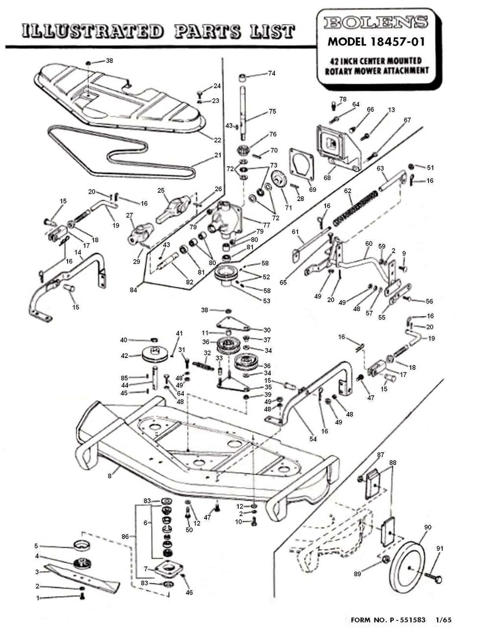
5 ROTARY MOWER MODEL Ref. Part Description Req d. Ref. Part Description Req d Capscrew H.T. Lockwasher /8 Mower Blade Drive Hub Cap Bearing Assy (See Note) Bearing Housing Base Carriage Bolt /8- x Capscrew Head Cap /8- x Spacer Flat Washer /8 Capscrew 5/-8 x -/ Bail R.H. Clevis Pin Spring Cotter Rod End Jam Nut 5/8- Link Rod Cotter Pin /8 x Drive Belt -5/ Belt Cover Lockwasher / Capscrew /-0 x / Universal Joint & Shaft Roll Pin / x -/ Universal Joint Roll Pin / x Cotter Pin Special Idler Arm Anchor Bolt Spring Spacer Bearing Idler Arm Idler Pulley Nut Special Jam Nut /8- Spacer Retaining Ring Set Screw 5/-8 x /8 Blade Drive Pulley Woodruff Key / x / Drive Shaft Sq. Key / x / * * Grease Fitting * 707 Repair Kit for Joint Marked N * 708 Repair Kit for Joint Marked NEAPCO NOTE: Sold only as assembly Do to Tolerances, requires complete matched bearing set including spacer and retaining ring positioned in housing if replacement of any individual part is necessary Carriage Bolt 5/-8 x / Lockwasher 5/ Hex Nut 5/-8 Capscrew /8- x -/ Lock Nut /8- Set Screw /8- x 5/ Pulley Bail L.H. Adjusting Arm Carriage Bolt 5/-8 x Flat Washer 5/ Lock Screw /8- x / Hex Nut /8- Lift Arm Guide Rod Spring Tube Capscew 5/-8 x 7/8 Capscew 5/-8 x -/ Plug Capscew /8- x -/ Gear Case Support Gasket Roll Pin / x -/ Gear 9T Thrust Race Thrust Bearing Needle Bearing Vertical Shaft Gear T Gear Case Only Air Vent Fitting Locknut 5/-8 Needle Bearing Seal Horizontal Shaft Seal Complete Gear Case Assy Woodruff Key / x 7/8 Housing & Bearing Assy WHEEL KIT MODEL 858 Nut Self Locking /- Clamp Wheel Support Nut Self Locking Jam /- Wheel 5 Dia. Bolt Special /- x -/ 8 8 5
6 This Word Document is password protected to preserve formatting and prevent modification. It was created from a PDF downloaded from My Tractor Forum.com - my thanks to them and Robert Wirsing for making this information available.
BrentChalmers.com. Owner Operation and Maintenance Manual ROTARY MOWER MODEL WISCONSIN,U.S.A. PORT ATTACHMENT 28 INCH WASHI~GTON,
 ROTARY MOWER Owner Operation and Maintenance Manual ATTACHMENT 28 INCH MODEL 15100-01 (2) Do not allow children to operate powered equipment at any time. The average child is not capable of coping with
GROUNDSMASTER. 52 Recycler. for 120 Traction Unit. Model No & UP. Operator s Manual
 FORM NO. 8-980 Rev A GROUNDSMASTER 5 Recycler for 0 Traction Unit Model No. 077 79000 & UP Operator s Manual IMPORTANT: Read this manual carefully. It contains information about your safety and the safety
Agri-Fab OWNERS MANUAL. Model No " ROUGH CUT TRAILMOWER. CAUTION: Read Rules for Safe Operation and Instructions Carefully
 Agri-Fab OWNERS MANUAL Model No. 45-0362 CAUTION: Read Rules for Safe Operation and Instructions Carefully Safety Assembly Operation Maintenance Parts 42" ROUGH CUT TRAILMOWER NOTE: Your mower deck will
ProLine. 44 Mower. for 120 Traction Unit. Model No & Up. Operator s Manual
 FORM NO. 9 ProLine Mower for 0 Traction Unit Model No. 05 99000 & Up Operator s Manual IMPORTANT: Read this manual carefully. It contains information about your safety and the safety of others. Also become
42" ROUGH CUT TRAILMOWER
 OWNERS MANUAL Model No. 45-03625 42" ROUGH CUT TRAILMOWER CAUTION: Read Rules for Safe Operation and Instructions Carefully IMPORTANT: BATTERY REQUIRED!! The battery is NOT included with the deck but must
Agri-Fab OWNERS MANUAL. Model No " ROUGH CUT TRAILMOWER. CAUTION: Read Rules for Safe Operation and Instructions Carefully
 Agri-Fab OWNERS MANUAL Model No. 45-03071 45-0361 CAUTION: Read Rules for Safe Operation and Instructions Carefully Safety Assembly Operation Maintenance Parts 42" ROUGH CUT TRAILMOWER the fastest way
owner operation and maintenance manual
 TEN-FIFTY owner operation and maintenance manual MODEL 192-02 SAFE OPERATING PRACTICES Serious accidents can be prevented. Every operator should approach the following safety practices with serious intentions
Wheel Horse. 42 Mower. for Lawn and Garden Tractors. Model No & Up. Operator s Manual
 FORM NO. 9 559 Rev A Wheel Horse 4 Mower for Lawn and Garden Tractors Model No. 78 890000 & Up Operator s Manual IMPORTANT: Read this manual carefully. It contains information about your safety and the
Z Master. 62 Mower. for Z Master Z 255 Traction Unit. Model No & UP. Operator s Manual
 FORM NO. 9 88 Z Master 6 Mower for Z Master Z 55 Traction Unit Model No. 7408 89000 & UP Operator s Manual IMPORTANT: Read this manual carefully. It contains information about your safety and the safety
ProLine. 36 Mower. for Mid-Size Traction Unit. Model No & Up. Operator s Manual
 FORM NO. 8 77 Rev A ProLine 6 Mower for Mid-Size Traction Unit Model No. 05 79000 & Up Operator s Manual IMPORTANT: Read this manual carefully. It contains information about your safety and the safety
Wheel Horse. 52 Mowers. Model No & Up Model No & Up. Operator s Manual
 FORM NO. 9-567 Wheel Horse 5 Mowers for Lawn & Garden Tractors Model No. 7880 890000 & Up Model No. 7885 890000 & Up Operator s Manual IMPORTANT: Read this manual carefully. It contains information about
BrentChalmers.com OWNERS MANUAL ~GRAVELV A DIVISION OF CLARKE-GRAVELY CORPORATION
 ~GRAVELV A DIVISION OF CLARKE-GRAVELY CORPORATION To continue its program of Qualitv and design improvement the man,,!factu~er reserve,s the rigt:.t to c,:",ange.specifi~atjons, design or prices without
44 and 52 Twin Bagger 100 Series Z Master
 Form No. 7 87 and 5 Twin Bagger 00 Series Z Master Model No. 7855 Serial No. 000000 and Up Operator s Manual English (CE) Contents Page Introduction................................ Safety.....................................
48 Side Discharge Mower
 FORM NO. 9 7GB Wheel Horse 48 Side Discharge Mower for Lawn & Garden Tractors Model No. 7868 790000 & Up Operator s Manual IMPORTANT: Read this manual carefully. It contains information about your safety
Wheel Horse. 44 Snowthrower. for 5xi Lawn and Garden Tractors. Model No & Up. Operator s Manual
 FORM NO. 8 Rev A Wheel Horse Snowthrower for 5xi Lawn and Garden Tractors Model No. 7966 890050 & Up Operator s Manual IMPORTANT: Read this manual, and your tractor manual, carefully. They contain information
Wheel Horse. 48 Mower. for Lawn and Garden Tractors. Model No & Up. Operator s Manual
 FORM NO. 5 Wheel Horse 48 Mower for Lawn and Garden Tractors Model No. 786 990000 & Up Operator s Manual IMPORTANT: Read this manual carefully. It contains information about your safety and the safety
Wheel Horse. 48 Mower. for 5xi Tractors. Model No & Up. Operator s Manual
 FORM NO. 9 Wheel Horse 48 Mower for 5xi Tractors Model No. 786 990000 & Up Operator s Manual IMPORTANT: Read this manual, and your tractor manual, carefully. They contain information about your safety
36 Rear Discharge Mower
 FORM NO. 8 95 Rev. A Wheel Horse 6 Rear Discharge Mower for Classic Garden Tractor Model No. 7805 790000 & Up Operator s Manual IMPORTANT: Read this manual carefully. It contains information about your
48 Side Discharge Mower
 FORM NO. 9 650 Rev A Wheel Horse 8 Side Discharge Mower for Classic Garden Tractor Model No. 786 890000 & Up Operator s Manual IMPORTANT: Read this manual carefully. It contains information about your
ROTARY TILLER. Operation, Service & Parts Manual For "AS" Series. FORM: ASTillerBook.QXD
 ROTARY TILLER Operation, Service & Parts Manual For "AS" Series FORM: ASTillerBook.QXD April 2002 TABLE OF CONTENTS Preparation......................................1 Assembly Instructions.............................2
Kubota Rear Discharge Mowers 1.3m
 Operating instructions and parts manual for Kubota Rear Discharge Mowers 1.3m (For G2160 Tractors) autoguide equipment Heddington, Nr Calne, Wiltshire, SN11 0PS Telephone: +44 (0) 1380 850885 Fax: +44
42 Mower Wheel Horse Classic Garden Tractor Attachment
 Form No. 6 9 Mower Wheel Horse Classic Garden Tractor Attachment Model No. 78 000000 and Up Operator s Manual Domestic English (EN) Contents Page Introduction................................ Slope Chart..............................
48 Mower Wheel Horse Classic Garden Tractor Attachment
 Form No. 6 96 Rev B 8 Mower Wheel Horse Classic Garden Tractor Attachment Model No. 786 000000 and Up Operator s Manual Domestic English (EN) Contents Page Introduction.................................
57 ROUGH CUT OWNER S MANUAL. With Assembly Instructions For Model: MR55H KUNZ ENGINEERING, INC. / MENDOTA, IL / PH (815) /07
 /07") 57 ROUGH CUT OWNER S MANUAL With Assembly Instructions For Model: MR55H KUNZ ENGINEERING, INC. / MENDOTA, IL 61342 / PH (815) 539-6954 1/07 ASSEMBLY INSTRUCTIONS Read the complete assembly instructions
57 ROUGH CUT OWNER S MANUAL With Assembly Instructions For Model: MR55H KUNZ ENGINEERING, INC. / MENDOTA, IL 61342 / PH (815) 539-6954 1/07 ASSEMBLY INSTRUCTIONS Read the complete assembly instructions
36 Tiller Wheel Horse Lawn and Garden Tractor Attachment
 Form No. 9 6 Rev B 6 Tiller Wheel Horse Lawn and Garden Tractor Attachment Model No. 797 890000 and Up Operator s Manual English(En) Contents Page Introduction................................ Safety.....................................
FORM NO GB Rev A OPERATOR S MANUAL MODEL NO & UP MODEL NO & UP REELMASTER 5100 CUTTING UNIT
 FORM NO. 3318-294 GB Rev A MODEL NO. 03505 60001 & UP MODEL NO. 03508 60001 & UP OPERATOR S MANUAL REELMASTER 5100 CUTTING UNIT The TORO COMPANY 1991, Rev. 1992, 1993, 1994 Table of Contents Page No. SPECIFICATIONS
Form No Wheel Horse. 52 in. Mower 5xi Tractor Attachment. Model No and Up. Operator s Manual. Domestic English (EN)
") Form No. -50 Wheel Horse 5 in. Mower 5xi Tractor Attachment Model No. 7870 0000000 and Up Operator s Manual Domestic English (EN) Contents Page Introduction................................ Safety and Instruction
Form No. -50 Wheel Horse 5 in. Mower 5xi Tractor Attachment Model No. 7870 0000000 and Up Operator s Manual Domestic English (EN) Contents Page Introduction................................ Safety and Instruction
57 ROUGH CUT WITH ELECTRIC CLUTCH BLADE ENGAGEMENT OWNER S MANUAL. With Assembly Instructions For Model: MR55KE
 57 ROUGH CUT WITH ELECTRIC CLUTCH BLADE ENGAGEMENT OWNER S MANUAL With Assembly Instructions For Model: MR55KE KUNZ ENGINEERING, INC. / MENDOTA, IL 61342 / PH (815) 539-6954 01/05 ASSEMBLY INSTRUCTIONS
52 inch Twin Bagger and Finishing Kit 200 Series Z Master
 Form No. 9 68 inch Twin Bagger and Finishing Kit 00 Series Z Master Model No. 7898 Serial No. 000000 and Up Model No. 780 Operator s Manual English (EN) Contents Page Introduction................................
57 ROUGH CUT OWNER S MANUAL. With Assembly Instructions For Models: MR55T, MR55B & MR55K
 57 ROUGH CUT MR55K MR55B OWNER S MANUAL With Assembly Instructions For Models: MR55T, MR55B & MR55K KUNZ ENGINEERING, INC. / MENDOTA, IL 61342 / PH (815) 539-6954 1/05 ASSEMBLY INSTRUCTIONS Read the complete
OWNERS MANUAL. Model No. LST42G 42" SNOW THROWER. Safety Assembly Operation Maintenance Parts
 OWNERS MANUAL Model No. LST42G 42" SNOW THROWER CAUTION: Read Rules for Safe Operation and Instructions Carefully Safety Assembly Operation Maintenance Parts the fastest way to purchase parts www.speedepart.com
57 ROUGH CUT OWNER S MANUAL. With Assembly Instructions. For Models: MR55T, MR55B-17.5HP, MR55B-22HP & MR55K
 57 ROUGH CUT MR55K MR55B OWNER S MANUAL With Assembly Instructions For Models: MR55T, MR55B-17.5HP, MR55B-22HP & MR55K KUNZ ENGINEERING, INC. / MENDOTA, IL 61342 / PH (815) 539-6954 1/07 ASSEMBLY INSTRUCTIONS
DM-135 DRUM MOWER USER S MANUAL
 DM-135 DRUM MOWER USER S MANUAL 1 DM135 DRUM MOWER INSTRUCTIONS CHAPTER 1 SAFE OPERATION Do not attempt to operate the mower until you have read the operator s manual and all the safety signs on the mower.
48in Snow Blade TimeCutter Z Riding Mower Attachment
 Form No. 9-8 8in Snow Blade TimeCutter Z Riding Mower Attachment Model No. 796 Serial No. 000000 and Up Operator s Manual Register your product at www.toro.com Original Instructions (EN, GB) Contents Page
ASSEMBLY INSTRUCTIONS
 ASSEMBLY INSTRUCTIONS Read the complete assembly instructions before starting the assembly. You should have: - one mower deck assembly - two carrier arm assemblies - two rear tire assemblies - one ATV
THE GIANT-VAC PTO BLOWER MODELS 2000*/3200**/4000***
 THE GIANT-VAC PTO BLOWER MODELS 2000*/3200**/4000*** Congratulations! ASSEMBLY INSTRUCTIONS AND OPERATOR S MANUAL You have just purchased one of the finest pieces of outdoor power equipment on the market
KING COBRA/CALIBER GRASS COLLECTION SYSTEM PARTS & OPERATORS MANUAL
 KING COBRA/CALIBER GRASS COLLECTION SYSTEM PARTS & OPERATORS MANUAL GRASS CATCHER W/WEIGHTS: TUBE KITS: BLOWER KITS: 52 542128 52 542119 5101002 60 542129 60 542120 5101003 2 WORLDLAWN POWER EQUIPMENT
Worldlawn Power Equipment, Inc. Industrial Park 2415 Ashland Ave. Beatrice, NE Toll Free Number:
 Operator s Manual R WYZ48/52/60CS BAGGER Worldlawn Power Equipment, Inc. Industrial Park 2415 Ashland Ave. Beatrice, NE 68310 Toll Free Number: 1-800-267-4255 OPERATOR S MANUAL This catcher manual is for
Collection System. Please read the operator s manual carefully and make sure you understand the instructions before using the machine.
 Collection System 967004601 Please read the operator s manual carefully and make sure you understand the instructions before using the machine. 2012 All rights reserved. Swainsboro, GA. Printed in U.S.A.
DFS Vac Collection System 400 Series Z Master
 Form No. 0 DFS Vac Collection System 00 Series Z Master Model No. 780 Serial No. 000000 and Up Operator s Manual Register your product at www.toro.com Original Instructions (EN/GB) Contents Page Introduction................................
62 Deck Idler Kit High Speed
 Part No. 00 FORM NO. -899 6 Deck Idler Kit High Speed For Model 70 Serial No. 99000 to 99000 For Model 7 Serial No. 9900 to 99000 INSTALLATION INSTRUCTIONS Loose Parts Note: Use the chart below to identify
Walker Loader Bucket OPERATOR S AND PARTS MANUAL
 Walker Loader Bucket OPERATOR S AND PARTS MANUAL Please Read and Save These Instructions For Safety, Read all Safety and Operation Instructions Prior To Operating Machine P/N 6690 TABLE OF CONTENTS Introduction
Operator s Manual. Commercial / Residential 33 Mower. Service Information Maintenance Mower Operation Adjustments & Repairs Warranty
 Operator s Manual R Commercial / Residential 33 Mower Service Information Maintenance Mower Operation Adjustments & Repairs Warranty Worldlawn Power Equipment, Inc. 422 Turnbull Canyon Road City of Industry
Quiet Collector. Model No & Up
 FORM NO. -8GB Rev A Quiet Collector Model No. 795-890000 & Up Operator s Manual IMPORTANT: Read this manual, and your tractor manual, carefully. They contain information about your safety and the safety
OWNERS MANUAL. Model No. LST42D 42" SNOW THROWER. Safety Assembly Operation Maintenance Parts
 OWNERS MANUAL Model No. LST42D 42" SNOW THROWER CAUTION: Read Rules for Safe Operation and Instructions Carefully Safety Assembly Operation Maintenance Parts the fastest way to purchase parts www.speedepart.com
Quiet Collector. Model No & Up
 FORM NO. -0 Quiet Collector Model No. 79-990000 & Up Operator s Manual IMPORTANT: Read this manual, and your tractor manual, carefully. They contain information about your safety and the safety of others.
ROTARY MOWER OPERATION, SERVICE & PARTS MANUAL FOR
 ROTARY MOWER OPERATION, SERVICE & PARTS MANUAL FOR L-G-40-40-P, L-G-48-40-P, L-G-60-40-P & L-G-72-40-P Slip Clutch Models: L-G-60-40-SC-P & L-G-72-40-SC-P February 2003 FORM: RotMwrBook.QXD TABLE OF CONTENTS
Model 858-RH. Operating and Assembly Manual. Palmor Products Inc Serum Plant Road Thorntown, IN 46071
 Model 5-RH Operating and Assembly Manual Palmor Products Inc. 55 Serum Plant Road Thorntown, IN 6071 3/31/015 SAFETY RULES Remember, any power equipment can cause injury if operated improperly or if the
Operator s Manual. Commercial / Residential 33 Mower. Service Information Maintenance Mower Operation Adjustments & Repairs Warranty
 Operator s Manual R Commercial / Residential 33 Mower Service Information Maintenance Mower Operation Adjustments & Repairs Warranty Worldlawn Power Equipment, Inc. 422 Turnbull Canyon Road City of Industry
HAMMER KNIFE FLAIL MOWER SHREDDER
 HAMMER KNIFE FLAIL MOWER SHREDDER Operation, Service, & Parts Manual For Models: GOL79 & GOL89 October 2010 FORM: GOLShredder.QXD TABLE OF CONTENTS Installation....................................................1
ILLUSTRATED PARTS LIST THIS MANUAL CONTAINS THE ILLUSTRATED PARTS LIST FOR MODELS:
 IPL MODEL SWZU 1 6 2 6 6 6 6 ILLUSTRATED PARTS LIST 0 2 6 8 THIS MANUAL CONTAINS THE ILLUSTRATED PARTS LIST FOR MODELS: SWZU6-1KA with a serial number of 260001 to 26 SWZU8-1KA with a serial number of
Operator's Manual. VC-60 & VC-60 Plus Harper Industries, Inc. 7/03 Part No
 Operator's Manual VC-60 & VC-60 Plus 2003 Harper Industries, Inc. 7/03 Part No. 970066 Thank you for purchasing a Harper/Goossen Verti-Cutter. As with all Harper/Goossen products, the Harper/Goossen Verti-Cutter
Section 2 - SAFETY MESSAGES AND SYMBOLS
 Section 2 - SAFETY MESSAGES AND SYMBOLS CHOKE "ON" "FAST" RABBIT I CHOKE ] I ENGINE SPEED I CHOKE "OFF" TURTLE "SLOW" 7 Section 2 - SAFETY MESSAGES AND SYMBOLS "START" I BLAOBSENGAGBO"ON" I BLAOBS DISENGAGED
OWNERS MANUAL. Model No. LST42B 42" SNOW THROWER. Safety Assembly Operation Maintenance Parts
 OWNERS MANUAL Model No. LST42B 42" SNOW THROWER CAUTION: Read Rules for Safe Operation and Instructions Carefully Safety Assembly Operation Maintenance Parts the fastest way to purchase parts www.speedepart.com
Adjustments manual for: Gear Drive, ETS Gear Drive, Walk Hydro, ETS Walk Hydro, Mini Rider, Large Rider Gen 2
 For Husqvarna Parts Call 66-678-96 or 66-56-98 Adjustments manual for: Gear Drive, ETS Gear Drive, Walk Hydro, ETS Walk Hydro, Mini Rider, Large Rider Gen MANUAL NO. 5957 REV. (//) For Husqvarna Parts
Safety Instructions, Installation & Operator s Manual For
 Safety Instructions, Installation & Operator s Manual For #6-3173 TWIN BAG GRASS CATCHER KIT FOR 38 YARD CRUISERS SERIES 2 MODEL YZ145382BVE IMPORTANT! THIS KIT NOT INTENDED FOR USE ON ANY SERIES OF HZ/HZS
Hydro Cut Series Walk-Behind Mowers
 Parts Manual HP Product Mfg. No. Description 92 Hydro Cut, HP Kawasaki, 2 inch (CE) Hydro Cut Series Walk-Behind Mowers Rev. 0/200 Table Of Contents PRODUCT COMPONENTS PAGES Engine Deck & Handle Bars
TECHNICAL DATA BROCHURE ZTR 308/3II
 Date 8/84 Page 1 of 6 TECHNICAL DATA BROCHURE ZTR 308/3II IMPORTANT - READ OPERATOR'S MANUAL BEFORE OPERATION OR MAKING ADJUSTMENTS. ' Seat Adjustment Loosen bolts on sliding brackets under each side of
Parts Manual. UltraBelt GD Walk Behind Mower
 Parts Manual UltraBelt GD Walk Behind Mower Models: Description: UltraBelt GD, 14HP Kohler w/ 36" Mower Deck 5900027 15HP Kawasaki V-Twin w/ 36" Mower Deck (AV15) 5900030 15HP Kawasaki V-Twin w/ 48" Mower
SETUP, PARTS & MAINTENANCE MANUAL 2 BAG CATCHER
 SETUP, PARTS & MAINTENANCE MANUAL 2 BAG CATCHER MODELS: 970338 2 BAG CATCHER, 36 970339 2 BAG CATCHER, 42 970340 2 BAG CATCHER, 48 970341 2 BAG CATCHER, 52 WARNING: If incorrectly used this machine can
GRASS CATCHER PART S & OPERATORS MANUAL
 GRASS CATCHER PART S & OPERATORS MANUAL WORLDLAWN POWER EQUIPMENT, INC. WORLDLAWN.COM 2415 ASHLAND AVE BEATRICE, NE 68310 800-267-4255 FAX 402-223-4103 2 3 4 OPERATORS MANUAL This catcher manual is for
WHEEL HORSE LAWN TRACTOR
 FORM NO. 897 WHEEL HORSE LAWN TRACTOR FOR AND 8 MOWERS SET-UP INSTRUCTIONS Loose Parts Note: Use the chart below to verify all parts have been shipped. DESCRIPTION QTY. USE Front Wheel Shim Washer (as
DIAMONDBACK/EDGE GRASS COLLECTION SYSTEM PARTS & OPERATORS MANUAL
 DIAMONDBACK/EDGE GRASS COLLECTION SYSTEM PARTS & OPERATORS MANUAL GRASS CATCHER W/WEIGHT: TUBE KIT: BLOWER KIT: 48 5101305 632093 632078 52 5101305 542119 632074 60 632086 542120 632081 3 WORLDLAWN POWER
42 Rear Discharge Mower, 42, 48, and 52 Side Discharge Mower Wheel Horse XT Series Garden Tractor Attachment
 Form No. 8 08 Rev A Rear Discharge Mower,, 8, and Side Discharge Mower Wheel Horse XT Series Garden Tractor Attachment Model No. 789 000000 and Up Model No. 789 000000 and Up Model No. 7890 000000 and
STOP 42"- 2 STAGE SNOW THROWER TRACTOR ATTACHMENT. Operator's Manual. Model No Safety Assembly Operation Maintenance Parts
 Operator's Manual STOP 42"- 2 STAGE SNOW THROWER TRACTOR ATTACHMENT Model No. 486.248381 DO NOT RETURN TO STORE For Missing Parts or Assembly Questions Call 1-866-576-8388 CAUTION: Before using this product,
Champion Series Zero-Turn Riders & Mower Decks
 Parts Manual Champion Series Zero-Turn Riders & Mower Decks HP Tractors Mfg. No. Description Champion, HP Zero-Turn Rider Champion, HP Zero-Turn Rider (CE) 0HP Tractors Mfg. No. Description Champion, 0HP
STOP 42" HIGH SPEED LAWNSWEEPER. Owner's Manual. Model No's Safety Assembly Operation Maintenance Parts
 Owner's Manual STOP 42" HIGH SPEED LAWNSWEEPER Model No's. 486.242223 DO NOT RETURN TO STORE For Missing Parts or Assembly Questions Call 1-866-576-8388 CAUTION: Before using this product, read this manual
Operating and Assembly Manual
 Model 380/385-IC/385-LH Operating and Assembly Manual Midwest Equipment Manufacturing, Inc. 5225 Serum Plant Road Thorntown, IN 46071 2-0916 SAFETY RULES Remember, any power equipment can cause injury
Wheel Horse. 48 Snow/Dozer Blade. Model No & Up. Operator s Manual
 FORM NO. 9 878 Rev A Wheel Horse 8 Snow/Dozer Blade for 5xi Lawn and Garden Tractors Model No. 7955 890000 & Up Operator s Manual IMPORTANT: Read this manual, and your tractor manual, carefully. They contain
Service Manual. Bolens 683 Series Box Frame Tractor IMPORTANT: READ SAFETY RULES AND INSTRUCTIONS CAREFULLY
 Service Manual Bolens 683 Series Box Frame Tractor IMPORTANT: READ SAFETY RULES AND INSTRUCTIONS CAREFULLY This Service Manual is not a substitute for the Operator s Manual. You must read, understand and
PARTS MANUAL SECTION 111
 P - SERIES ZERO TURN MOWER MODELS P5525CT, P6124FS, P6126KP, P6127CT Published 11/15 S MANUAL SECTION 111 An Operator's Manual was shipped with the equipment. The Operator's Manual is an integral part
CUTTER DECK. * Purchase part Shear Bolt Package to replace these parts. (4 of each per package)
") 0 0 0 0 CUTTER DECK 0 0S00 CUTTER DECK Foot Plate 00-0 Serr. Fl. Hex Nut, /- -0 Grease Fitting Frame, Cutter Deck Support (incl.,,) 00-0 Hex Locknut, Elastic Stop, /- 0 Rod, Deck Prop - L.H. 00- Serr.
0 0 0 0 CUTTER DECK 0 0S00 CUTTER DECK Foot Plate 00-0 Serr. Fl. Hex Nut, /- -0 Grease Fitting Frame, Cutter Deck Support (incl.,,) 00-0 Hex Locknut, Elastic Stop, /- 0 Rod, Deck Prop - L.H. 00- Serr.
ILLUSTRATED PARTS LIST THIS MANUAL CONTAINS THE ILLUSTRATED PARTS LIST FOR MODELS:
 IPL MODEL STHM 7 1 0 1 1 2 1 0 2 ILLUSTRATED PARTS LIST THIS MANUAL CONTAINS THE ILLUSTRATED PARTS LIST FOR MODELS: STHM-2CV SM-1V SM-72A with a serial number of D00001 to D with a serial number of D00001
HAMMER KNIFE FLAIL MOWER SHREDDER
 HAMMER KNIFE FLAIL MOWER SHREDDER Operation, Service, & Parts Manual For Models: GOF69, 79, 89, 98, & 108 February 2006 Rev. 2009 FORM: GOFMower.QXD TABLE OF CONTENTS Installation....................................................1
THE FINISHING TOUCH 42 FINISH CUT MOWER SELF PROPELLED WALK BEHIND
 Visit us at: www.swisherinc.com OWNER S MANUAL STARTING SERIAL #: L105-074001 MODEL NO. WB11542F Rev. Important! Read and follow all Safety Rules and Instructions before operating this equipment. THE FINISHING
Models: Operator s Manual KIKW36150 KIKW48150 KIKW48170 MANUAL REV. IR (02/16/04)
") Operator s Manual Models: KIKW36150 KIKW48150 KIKW48170 MANUAL 110567 REV. IR (02/16/04) Thank you for buying a YAZOO/KEES! Before operating your new mower, read, understand and follow the important safety
Operator s Manual Models: KIKW36150 KIKW48150 KIKW48170 MANUAL 110567 REV. IR (02/16/04) Thank you for buying a YAZOO/KEES! Before operating your new mower, read, understand and follow the important safety
Model No POINT REVERSE TINE TILLER. Safety Assembly Operating Maintenance Repair Parts
 owners manual Model No. 45-0385 3-POINT REVERSE TINE TILLER CAUTION: Read Rules for Safe Operation and Instructions Carefully Safety Assembly Operating Maintenance Repair Parts the fastest way to purchase
STOP UNIVERSAL TILLER 36" TOW-BEHIND. Model No Owner's Manual. Safety Assembly Operation Maintenance Parts
 Owner's Manual STOP 36" TOW-BEHIND UNIVERSAL TILLER Model No. 486.252444 DO NOT RETURN TO STORE For Missing Parts or Assembly Questions Call 1-866-576-8388 CAUTION: Before using this product, read this
Collector Drive for 44 Mower
 FORM NO. -80 Collector Drive for Mower Model No. 7955-990000 & Up Operator s Manual IMPORTANT: Read this manual, and your tractor manual, carefully. They contain information about your safety and the safety
TECHNICAL DATA BROCHURE ZTR 426
 TECHNICAL DATA BROCHURE ZTR 426 Date 8/84 IMPORTANT - READ OPERATOR'S MANUAL BEFORE OPERATION. Page 1 of 6 Seat Adjustment Loosen bolts on sliding bracket under each side of seat, slide seat forward or
Rear Roller Brush Kit Greensmaster 3150 & 3250
 Rear Roller Brush Kit Greensmaster 50 & 50 Model No. 04640 Model No. 0464 Form No. 8 808 Rev. B Installation Instructions Note: The Rear Roller Brush Kit can only be installed on cutting unit models 0460
Collector Drive for 60 Mower
 FORM NO. -66 Collector Drive for 60 Mower Model No. 7965-990000 & Up Operator s Manual IMPORTANT: Read this manual, and your tractor manual, carefully. They contain information about your safety and the
ILLUSTRATED PARTS LIST THIS MANUAL CONTAINS THE ILLUSTRATED PARTS LIST FOR MODELS:
 IPL MODEL SWZU 71 7 7 7 ILLUSTRATED PARTS LIST 70 7 THIS MANUAL CONTAINS THE ILLUSTRATED PARTS LIST FOR MODELS: SWZUA-KAI with a serial number of C00001 to C SWZUV-17KAI with a serial number of C00001
CREATIVE EQUIPMENT CC 18 Main Road, Fishers Hill, Germiston, 1401 Tel: Fax:
 FRAME & DRIVE IDLER ASSEMBLY REF # PART # DESCRIPTION 1 MTD603-04680A FRAME ASSY 2 MTD703-05829 DRIVE IDLER ARM 3 MTD710-0520 HEX SCREW, 3/8-16 x 1.5 4 MTD710-3005 HEX SCREW, 3/8-16 x 1.25 5 MTD712-04065
Z-Force 48 CUB CADET LLC, P.O. BOX CLEVELAND, OHIO Printed In USA
 Illustrated Parts Manual Z-Force CUB CADET LLC, P.O. BOX CLEVELAND, OHIO -00 Printed In USA Form No. -0 February, 0 To The Owner Thank You Thank you for purchasing a Cub Cadet Zero-Turn Tractor. It was
Reproduction. Not for OPERATOR S MANUAL. Turbo Vacuum System. Model Description Turbo Vacuum Collection System (For 60 Mower Decks)
") OPERATOR S MANUAL Turbo Vacuum System Model Description 1695759 Turbo Vacuum Collection System (For 60 Mower Decks) Copyright Briggs & Stratton Power Products Group, LLC Milwaukee, WI USA. All Rights Reserved.
OPERATOR S MANUAL Turbo Vacuum System Model Description 1695759 Turbo Vacuum Collection System (For 60 Mower Decks) Copyright Briggs & Stratton Power Products Group, LLC Milwaukee, WI USA. All Rights Reserved.
Operator and Parts Manual
 Operator and Parts Manual Blower Kit 42" Collection System 966529101 2010 HTC. All Rights Reserved. Beatrice, NE. Printed in U.S.A. CONTENTS SAFETY RULES...4 ASSEMBLY...6 OPERATION...10 TIPS FOR IMPROVED
42in GT Classic Single Stage Snowthrower Conversion Kit XT Series Garden Tractor
 Form No. 9 66 in GT Classic Single Stage Snowthrower Conversion Kit XT Series Garden Tractor Part No. 06 88 Installation Instructions English (EN) This kit is for installing an existing 00 Series Classic
ENGINE DRIVEN ROTARY MOWER
 ENGINE DRIVEN ROTARY MOWER Operation, Service & Parts Manual For Models ERM-413, 416, & 617 April 2009 Form: ERMHydMower TABLE OF CONTENTS SECTION DESCRIPTION...PAGE 1 Introduction... 1 2 Preparation...2
Agri-Fab OWNERS MANUAL. Model No " FINISH CUT TRAILMOWER. CAUTION: Read Rules for Safe Operation and Instructions Carefully
 Agri-Fab OWNERS MANUAL Model No. 45-0305 63" FINISH CUT TRAILMOWER CAUTION: Read Rules for Safe Operation and Instructions Carefully NOTE: Your mower deck will require a 12 volt battery to operate. This
ROTARY TILLER. Operation, Service & Parts Manual For P-P/C Series. November 1996 (Rev. 4-05) FORM: PTillerBook.QXD
 FORM: PTillerBook.QXD") ROTARY TILLER Operation, Service & Parts Manual For P-P/C Series FORM: PTillerBook.QXD November 1996 (Rev. 4-05) TABLE OF CONTENTS Preparation......................................1 Assembly Instructions.............................2
ROTARY TILLER Operation, Service & Parts Manual For P-P/C Series FORM: PTillerBook.QXD November 1996 (Rev. 4-05) TABLE OF CONTENTS Preparation......................................1 Assembly Instructions.............................2
Parts Manual. Coronet / 2400 Series Riders & Mower Decks RMO. 13HP Product. 16HP Product. Mower Decks
 Parts Manual 13HP Product Mfg. No. Description 1694610 Coronet, 13HP Hydro RMO Coronet / 2400 Series Riders & Mower Decks RMO 1694612 Coronet, 13HP Hydro RMO (CE) 1694613 2413H, 13HP Hydro RMO 1694614
Operating and Assembly Manual
 Model 1080 Operating and Assembly Manual Midwest Equipment Manufacturing, Inc. 5225 Serum Plant Road Thorntown, IN 46071 08-02-16 SAFETY RULES Remember, any power equipment can cause injury if operated
Pacer Series Transaxle Drive Walk-Behind Mower
 Parts Manual Pacer Series Transaxle Drive Walk-Behind Mower 15HP Product Mfg. No. Description 1694895 Pacer, 15HP B&S Walk-Behind 2690447 Pacer, 15HP B&S w/34" Deck 17HP Product Mfg. No. Description 5900630
THE GIANT-VAC GIANT THATCHER MODELS 55GT 55GTH 91GT
 THE GIANT-VAC GIANT THATCHER MODELS 55GT 55GTH 91GT ASSEMBLY GUIDE AND OPERATOR S MANUAL As you unpack your Giant-Thatcher power unit, you will find the following parts: 1 - Power unit with motor, thatcher
Installation Instructions Z-Gate Shifter
 Installation Instructions Z-Gate Shifter Part Number 80681 1998, 2001 by B&M Racing and Performance Products The B&M Z-Gate shifter can be used in vehicles equipped with most popular three speed automatic
STOP 42"- 2 STAGE SNOW THROWER TRACTOR ATTACHMENT. Operator's Manual. Model No Safety Assembly Operation Maintenance Parts
 Operator's Manual STOP 42"- 2 STAGE SNOW THROWER TRACTOR ATTACHMENT Model No. 486.248371 DO NOT RETURN TO STORE For Missing Parts or Assembly Questions Call 1-866-576-8388 FITS HUSQVARNA TRACTORS AND CRAFTSMAN
HYDRAULICS. TX420 & & lower. Hydraulic Tandem Pump Removal. 4. Remove the LH side panel (Fig. 0388).
.") TX420 & 425 240000299 & lower 4. Remove the LH side panel (Fig. 0388). Hydraulic Tandem Pump Removal Note: Cleanliness is a key factor in a successful repair of any hydraulic system. Thoroughly clean all
TX420 & 425 240000299 & lower 4. Remove the LH side panel (Fig. 0388). Hydraulic Tandem Pump Removal Note: Cleanliness is a key factor in a successful repair of any hydraulic system. Thoroughly clean all
Wheel Horse. 36 Tiller. Model No & Up. Operator s Manual
 FORM NO. 8 9 Rev. A Wheel Horse 6 Tiller for Classic Garden Tractors Model No. 7970 690000 & Up Operator s Manual IMPORTANT: Read this manual carefully. It contains information about your safety and the
Wheel Horse 48 Blade for 5xi Garden Tractors
 Form No. -9 Wheel Horse 8 Blade for 5xi Garden Tractors Model 7955 0000000 Operator s Manual Domestic English (EN) Contents Page Introduction................................ Installation.................................