Makotherm Thermal / Catalytic Oxidizer Operation and Maintenance Manual
|
|
|
- Matthew Newton
- 5 years ago
- Views:
Transcription
1 Makotherm Thermal / Catalytic Oxidizer Operation and Maintenance Manual GENERAL INFORMATION FOR UNIT The Thermal / Catalytic Oxidizer with a Blower Package is used for the remediation of soils with volatile organic compounds which are present from leakage or spillage. The unit is most effective when the soil vapor concentration yield is nominally between 500 and 15,000 parts per million by volume. Soil vapors are extracted with the blower through the entrained liquid separator, which removes the majority of the water brought up from the soil during the vacuum extraction process. Dilution air is added if necessary and the vapors proceed to the oxidizer chamber where the burner heats them to their final temperature of 1,450 o F +. The vapors come into contact with the flame and combust into water vapor and carbon dioxide. The destruction efficiency for the unit is 98% or above. The unit is described more thoroughly in the technical specification section of this document. TECHNICAL SPECIFICATIONS VOC Processing Capability: The Thermal / Catalytic Oxidizer can treat up to 15,000 ppmv of BTEX type VOC s including MTBE. Destruction Efficiency: The Destruction Efficiency is 98% +. Major Components Entrainment Separator: The Entrainment Separator is provided to remove water that is brought up during vapor extraction from the vapor stream. It has a tangential inlet that cyclonically separates the water from the vapors with 99% + efficiency. It also has a demister element to remove incoming particulate and water droplets. Vacuum Blower: The Vacuum Blower extracts the vapors from the soil and can produce vacuum levels from 1 inch of water to 350 inches of water. The pump is powered by a motor, which is sized to provide enough horsepower to generate the flow required at the specified vacuum level for the system. (see your specific quotation and specifications for exact blower / horsepower for your unit). 1
2 Oxidizer Chamber: The Oxidizer Chamber is constructed of 3/16 inch carbon steel and lined with a 5 inch ceramic fiber high temperature lining that provides a safe cold face temperature while operating at 1450 o F + on the hot face. Burner and Fuel Train: An excess air burner is installed on the oxidizer chamber. This provides the necessary heat for the pre-heating of the incoming vapors. The operating range for the burner is 1450 o F to 1800 o F. The fuel train is a NFPA double blocking valve type with proportional gas modulation depending on temperature. Control Panel: The Control Panel contains a main disconnect, on/off switches, operator interface lights, controllers, chart recorder, fuses, motor starters, relays and wiring. The panel is a NEMA 4 type for outdoor use. Valves: The Entrainment Separator comes equipped with two butterfly valves, which are actuated by a drive motor. One is a Process Isolation Valve that is provided to isolate the vapors during start-up, when an alarm occurs or when the oxidizer is not at temperature. The other is a Dilution Valve that continually modulates and maintains the outlet temperature at a pre-set level. Auto Drain Pump: A Liquid Pump is provided to remove the water accumulated in the entrainment separator. The pump is activated when the water reaches the high liquid level switch and shuts off when it reaches the low-level switch. The pump transfers the water to a receptacle provided by the client at the site. Liquid Level Switches: Liquid Level Switches are provided on the entrainment separator and the oil seal tank. A High Liquid Level Switch activates the liquid transfer pump when it is triggered. Flow Transmitter: The Flow Transmitter receives a high and low air pressure signal from the pitot tube or orifice plate in the process line and transmits a signal to the chart recorder. The chart recorder records the total volumetric flow rate passing to the oxidizer. Temperature Controller: The Temperature Controller receives a signal from the control thermocouple and maintains the pre-set temperature by modulating the fuel-train drive motor and valve. Dilution Controller: The Dilution Controller receives a signal from the stack thermocouple and maintains the pre-set temperature by modulating the dilution drive motor and valve. High Limit Temperature Controller: The High Limit Temperature Controller receives a signal from the stack thermocouple and shuts the oxidizer off if the exhaust temperature exceeds 1800 o F in the Thermal mode or 1150 o F in the Catalytic mode. 2
3 Treatment System SYSTEM WARNINGS The Treatment System utilizes high temperatures, high voltages and flammable vapors to operate. All personnel operating the Treatment System must be trained in the operation and maintenance of the system as well as the safety devices provided with the system. 1. Do not attempt to bypass any of the safety interlocks provided in an attempt to operate the unit. Unless authorized by Mako personnel for diagnostic purposes only. Bypassing safety switches will void the warranty and can cause major damage to equipment and personnel. 2. Do not modify or bypass the transformers, fuse blocks, or controllers in order to make the system operational unless authorized by Mako personnel. 3. Do not remove any equipment from the unit in order to make the unit operational. 4. Keep all body parts clear of the exhaust stack, oxidizer chamber, burner, air intake valves and moving parts due to burns from high temperature conditions and severe bodily injury situations that can occur as a result of body contact with these parts. 5. Do not restrict, block or close the exhaust stack during operation. 6. Disconnect incoming voltage to the unit control panel before attempting to work on the panel or other electrical components on the unit. Use a voltage meter to determine that the power is off. Have only qualified personnel work on the electrical components, preferably a qualified electrician. 7. Verify that propane is secure and that no there are no leaks in the lines. 8. Shutdown the system and contact Mako immediately if you are experiencing any unsafe conditions. 3
4 SYSTEM INSTALLATION AND START-UP Follow each step listed here in exactly the order listed. For your safety, do not skip any steps or perform any steps out of order. Installation: 1. Operate the unit on a level dry surface. 2. Connect the properly rated electrical supply with a ground from the generator to the control panel main disconnect using a qualified electrician. 3. Check voltage, wire size and amperage rating of electricity installed, making sure that it matches the manufacturers panel specifications and electrical drawings for your specific system before proceeding. 4. Check 120-volt power circuit to see that controllers are powered up. 5. Check rotation of the Vacuum blower, combustion blower and liquid transfer pump making sure they are correct. 6. Check natural gas / propane supply making sure it is connected to the inlet piping from the supply source. Insure there is no leakage from any of the lines with a soap bubble test. Start-up Procedures: 1. Verify that the Main Disconnect Switch on the control panel is in the Off position. 2. Open the system control panel door and have a qualified electrician verify that the voltage at top of the Main Disconnect is set to the specified voltage. 3. With the control panel door closed and latched, turn the Main Disconnect switch to the On position. 4. Turn the Control Power switch to the On position. 5. Push the Start button, the vacuum blower should come on after pushing the Start Button. 6. Press the Limits Reset Button the limits operational light should come on if all limits are in a safe condition. 7. The unit should purge for 60 seconds and then attempt to light the burner. 8. If the unit burner lights, the unit will heat the unit to 1400 degrees at which time the well isolation valve should open and the unit will begin to process vapors. In the Catalytic mode the unit should heat to 600 degrees and then open the process valve. 4
5 System Alarms 1. High Water Alarm Entrained Liquid Tank: Water level is above the high/high level switch in the entrained liquid separator. Blower immediately shuts off and unit is shutdown. 2. Low Gas Pressure Fuel Train: Gas pressure is below 4 water column at the inlet to the fuel train. Unit closes the process valve and shuts off the burner. Unit will re-light if the condition corrects itself within 30 minutes. 3. High Gas Pressure Fuel Train: Gas pressure is above 1 pound at the inlet to the fuel train. Unit closes the process valve and shuts off the burner. Unit will re-light if the condition corrects itself within 30 minutes. 4. High Temperature Oxidizer Exhaust: Exhaust temperature in the oxidizer stack has exceeded 1800 degrees F in the Thermal Mode or 1150 degrees F in the Catalytic Mode. Unit closes the process valve and shuts off the burner. Unit shuts down in 30 minutes and needs to be manually reset. 5. Combustion Air Flow Alarm: Combustion air blower is not producing enough airflow or is off. Unit closes the process valve and shuts off the burner. Unit shuts down in 30 minutes and needs to be manually reset. 6. Flame Failure Burner: Burner did not light. Unit closes the process valve and shuts off the burner. Unit shuts down in 30 minutes and needs to be manually reset. 5
6 MAINTENANCE SHEDULE Check Blower Monthly (Maintenance procedure in product bulletin) Grease Motor fittings Monthly (Use grease gun on zirk fittings, give two pumps to the fittings) Check Panel Wire connections Monthly (Tighten them if necessary) Check Entrainment Separator Filter Tri-Yearly (Remove Entrainment Separator lid, clean or replace as needed) Clean out Entrainment Separator Weekly (Use clean water to rinse sides and remove hand clean out for debris) Clean Level Switches and Site Glass Weekly (Use clean water to rinse out debris) Check Water Pump Monthly (Insure proper operation) Check Flow Transmitter Weekly Check Thermocouple wiring at Thermocouple Bi-Yearly (Open T/C head and inspect wiring, change if necessary) Check Drive Motor linkage on valves Monthly (Check adjustment screws, tighten if necessary) Lubricate Butterfly Valves Weekly (Spray WD-40 into valve area under vacuum) Check level switches Monthly (Insure proper operation) 6
7 Catalytic Operation When converting unit to catalytic operation do the following prior to use while catalyst installed or damage can occur to the cell: 1. Cool unit down to safe temperature range to work on unit 2. Open side door hatch catalyst receptacle should be clean and free of debris. 3. Install catalyst cell with refractory cement as a caulking seal below lower outer edge of catalyst and shelf ledge. 4. Re-seal catalyst cell door with ceramic gasket in place and all fasteners tight. 5. Access temperature controller and change controller set point to 650 degrees. 6. Change alarm 1 set point in temperature controller to 600 degrees. 7. Change dilution controller set point to 1000 degrees 8. Change high limit controller set point to 1150 degrees. 7
8 AA...A2 Installation Instructions SPECIFICATIONS AA...A2 SPDT differential pressure switch for pressure and/or vacuum ranges. The differential pressure acts via the diaphragm against the force of the setting spring on the microswitch. The pressure switch operates without any auxiliary power. Gases Air and non-aggressive gases only. Not suitable for natural gas, propane, butane or other combustable gases. Switch SPDT Switch action Pressure, vacuum or differential pressure switch. Contact Rating 5 A resistive, 2.5 A Vac Electrical Connection Screw terminals via 1/2" NPT conduit connection Enclosure NEMA Type 4 Maximum Operating Pressure 7 PSI (500 mbar) Ambient / Medium Temperature -40 F to +140 F (-40 C to +60 C) Materials in contact with Gas Housing: Polycarbonate Switch: Polycarbonate Diaphragms: NBR-based rubber Switching contact: Silver (Ag) Approvals UL Listed: File No. MH CSA Certified: Certification # FM Approved: Report J.I. 1T7A8.AF ATTENTION Read these instructions carefully. Failure to follow them and/or improper installation may cause explosion, property damage and injuries. Installation must be done with the supervision of a licensed burner technician. The system must meet all applicable national and local code requirements. Check the ratings in the specifications and on the switch to make sure that it is suitable for your application. Never perform work if gas pressure or power is applied, or in the presence of an open flame. Once installed, perform a complete checkout including leak testing. Label all wires prior to disconnection when servicing. Wiring errors can cause improper and dangerous operation Verify proper operation after servicing. Definition of switching hysteresis p The pressure difference between the upper and lower switching pressures. OPERATION A2 Installation Manual /2002 Pressure at meter Switching hysteresis p Setpoint tolerance Installation position Standard installation position is vertical upright diaphragm. When installed horizontally, the pressure switch switches at a pressure higher by approx. 0.2 in. W.C. When installed upside down, the pressure switch switches at a pressure lower by approx. 0.2 in. W.C. When installed in other positions, the pressure switch switches at pressure deviating from the set reference value by max. ± 0.2 in. W.C. KARL DUNGS INC. 524 Apollo Drive,Suite 10 Lino Lakes, MN U.S.A. 1 2 Phone: (651) Fax: (651) info@karldungsusa.com Adjustment as pressure rises Upper switching pressure Rising Falling Lower switching pressure
9 1.8 (45,5) AA...A2-4 Hose Connection 1.0 (24,9) 0.3 (6,9) Ø 0.2 (4,6) Ø 0.1 (2,5) 0.7 (18,5) 0.4 (10) 0.7 (18,5) PRESSURE CONNECTIONS 1.8 (44,6) Ø 0.1 x 0.3 (3 x 8) deep 2.8 (72) AA...A2-6 Threaded Connection 2.3 (59) 1.2 (31,4) 0.3 (7) 0.3 (8) A Ø 0.1 (2,5) 0.7 (18,5) 0.4 (10) (1) 1/4 NPT 0.7 (18,5) Pressure connection can only be used as test nipple. (3) Test Nipple Dimensions inch (mm) (1) Pressure connection (+) (2) Pressure connection ( ) (3) Test nipple p (+) 2.8 (72) Test Button ø 0.1 x 0.4 (3 x 10) deep Ø 0.2 (4,2) 0.8 (20) (1) 0.6 (15) (2) 3.2 (82) 2.1 (53,7) LK Ø 3.1 (78,8) LK Ø 3.0 (76) Made in Germany 1.8 (44,6) (2) 1/8 NPT 0.6 (15) Made in Germany 3.2 (82) 2.1 (53,7) LK Ø 3.1 (78,8) LK Ø 3.0 (76) Made in Germany Ø 0.2 (4,2) 0.4 (10) Made in Germany 3.2 (82) ax. torq que 65 in. Lbs M. 1/2 NPT Conduit Connection 2.1 (53,7) 0.6 (15,2) AA...A2-4 Mounting Procedure Use suitable hoses for the medium. Use a maximum 5/32 ID. hose Secure the hoses with a cable tie or a cable clip. 0.6 (15,2) 0.3 (6,5) 3.1 (78,5) 3.4 (87,5) ax. torq que 65 in. Lbs M. 2.1 (53,7) AA...A2-6 Mounting Procedure Apply good quality pipe sealant to the male threads only. Use 13/16 Wrench to secure the switch to the pipe. DO NOT Exceed 45 lb-in of Torque on 1/8 Connections DO NOT Exceed 60 lb-in of Torque on 1/4 Connections After installation is complete, perform a leak test. A2 test button When the test button is pressed the 1/4" NPT pressure connection is interrupted and the pressure below the diaphragm is relieved. The pressure switch changes the contact position from NO to NC. When the test button is released, the pressure is built up again and the switch changes to its original position. Remove the clear cover from the switch. Use 14 or 16 AWG wire rated for at least 75 C Route the wires through the conduit connector Connect the wiring to the appropriate screw terminals. Replace the clear cover from the switch. CAUTION: All wiring must comply with local electrical codes, ordinances and regulations. CAUTION: Do not exceed the switch ratings given in the specifications and on the switch. WIRING AA...A2 switching function As pressure rises: 1 NC opens, 2 NO closes As pressure falls: 1 NC closes, 2 NO opens COM 3 (P) p 2 1 NO NC Medium Pressure Adjusting the Set Point Remove the clear cover from the switch. Adjust the set point to the desired set point pressure by turning the dial until the desired pressure is opposite the white arrow on the blue dial face. After adjusting the set point for normal operation check to see that the gas pressure switch operates as intended. ADJUSTMENT Use an accurate pressure gauge connected upstream from the switch to measure the actual pressure. Replace the clear cover. Automatic Reset The NC contact of the AA...A2 breaks when pressure rises above the set point. It makes automatically when pressure falls below set point. 2 2
10 Design Guide /01 ThermAir Burners TA Series version 1.10
11 COPYRIGHT DISCLAIMER NOTICE LIABILITY AND WARRANTY Copyright I998 by Eclipse Combustion, Inc. All rights reserved worldwide. This publication is protected by federal regulation and shall not be copied, distributed, transmitted, transcribed or translated into any human or computer language, in any form or by any means, to any third parties, without the express written consent of Eclipse Combustion, Inc., Rockford, Illinois, U.S.A. We reserve the right to change the construction and/or configuration of our products at any time without being obliged to adjust earlier supplies accordingly. The material in this manual is believed adequate for the intended use of the product. If the product, or its individual modules or procedures, are used for purposes other than those specified herein, confirmation of their validity and suitability must be obtained. Eclipse Combustion, Inc. warrants that the material itself does not infringe any United States patents. No further warranty is expressed or implied. We have made every effort to make this manual as accurate and complete as possible. Should you find errors or omissions, please bring them to our attention so that we may correct them. In this way we hope to improve our product documentation for the benefit of our customers. Please send your corrections and comments to our Documentation Manager. It must be understood that Eclipse Combustion s liability for its products, whether due to breach of warranty, negligence, strict liability, or otherwise, is limited to the furnishing of such replacement parts and Eclipse Combustion will not be liable for any other injury, loss, damage or expenses, whether direct or consequential, including but not limited to loss of use, income of or damage to material arising in connection with the sale, installation, use of, inability to use or the repair or replacement of Eclipse Combustion s products. Any operation expressly prohibited in this Guide, any adjustment, or assembly procedures not recommended or authorized in these instructions shall void the warranty. 2 Eclipse ThermAir T/A Series v1.10, Design Guide No. 114, 10/01
12 About this manual AUDIENCE This manual has been written for people who are already familiar with all aspects of a nozzle-mix burner and its add-on components, also referred to as the burner system. These aspects are: design/selection use maintenance. The audience is expected to have had experience with this kind of equipment. THERMAIR DOCUMENTS Design Guide No. 114 This document ThermAir Data Sheets, Series 114 Available for individual TA models Required to complete design & selection Installation Guide No. 114 Used with Data Sheet to complete installation ThermAir Price List No. 114 Used to order burners RELATED DOCUMENTS EFE 825 (Combustion Engineering Guide) Eclipse Bulletins and Info Guides: 710, 732, 742, 760, 818, 832, 852, 854, 856, 610, 620, 630, 826, 820, 930, I-354. Purpose The purpose of this manual is to ensure that the design of a safe, effective, and trouble-free combustion system is carried out. Eclipse ThermAir T/A Series v1.10, Design Guide No. 114, 10/01 3
13 DOCUMENT CONVENTIONS There are several special symbols in this document. You must know their meaning and importance. The explanation of these symbols follows below. Please read it thoroughly. d Danger: Indicates hazards or unsafe practices which WILL result in severe personal injury or even death. Only qualified and well trained personnel are allowed to carry out these instructions or procedures. Act with great care and follow the instructions. w Warning: Indicates hazards or unsafe pratices which could result in severe personal injury or damage. Act with great care and follow the instructions. c Caution: Indicates hazards or unsafe practices which could result in damage to the machine or minor personal injury, Act carefully. n Note: Indicates an important part of the text. Read thoroughly. HOW TO GET HELP If you need help, contact your local Eclipse Combustion representative. You can also contact Eclipse Combustion at any of the addresses listed on the back of this document. 4 Eclipse ThermAir T/A Series v1.10, Design Guide No. 114, 10/01
14 Table of contents About this manual Audience ThermAir Documents Related Documents Document Conventions How to Get Help Table of Contents Introduction Product Description Safety Capabilities Operator Training Replacement Parts System Design Burner Option Selection Blower Option Selection Control Methodology Ignition System Flame Monitoring Control System Main Gas Shut-Off Valve Train Appendix Conversion Factors Key To System Schematics Eclipse ThermAir T/A Series v1.10, Design Guide No. 114, 10/01 5
15 6 Eclipse ThermAir T/A Series v1.10, Design Guide No. 114, 10/01
16 Introduction 1 PRODUCT DESCRIPTION The ThermAir burner (TA Series) is a nozzle-mix burner with a packaged combustion air blower that is designed to fire with fixed combustion air over a wide gas turndown range. An integral gas orifice is provided to ease burner setup. The burner is designed to facilitate: fixed air operation direct spark ignition simple gas control multiple fuel capability The burner is suitable for direct and indirect air heating for a wide range of applications on industrial furnaces and ovens. Figure 1.1 ThermAir Burner Eclipse ThermAir T/A Series v1.10, Design Guide No. 114, 10/01 7
17 8 Eclipse ThermAir T/A Series v1.10, Design Guide No. 114, 10/01
18 Safety 2 INTRODUCTION SAFETY This section is provided as a guide for the safe operation of the ThermAir burner system. All involved personnel should read this section carefully before operating this system. d Danger: The ThermAir burners, described herein, are designed to mix fuel with air and burn the resulting mixture. All fuel burning devices are capable of producing fires and explosions if improperly applied, installed, adjusted, controlled, or maintained. Do not bypass any safety feature; fire or explosion could result. Never try to light a burner if it shows signs of damage or malfunction. w Warning: The burner might have HOT surfaces. Always wear protective clothing when approaching the burner. n Note: This manual provides information in the use of these burners for their specific design purpose. Do not deviate from any instructions or application limits described herein without written advice from Eclipse Combustion. Read the entire manual before attempting to start this system. If you do not understand any part of the information contained in this manual, contact your local Eclipse representative or Eclipse Combustion before continuing. Eclipse ThermAir T/A Series v1.10, Design Guide No. 114, 10/01 9
19 CAPABILITIES Only qualified personnel, with good mechanical aptitude and experience on combustion equipment, should adjust, maintain, or troubleshoot any mechanical or electrical part of this system. OPERATOR TRAINING REPLACEMENT PARTS The best safety precaution is an alert and trained operator. Train new operators thoroughly and have them demonstrate an adequate understanding of the equipment and its operation. A regular retraining schedule should be administered to ensure operators maintain a high degree of proficiency. Order replacement parts from Eclipse Combustion only. All Eclipse Combustion approved, customer supplied valves or switches should carry UL, FM, CSA, CGA, and/or CE approval, where applicable. 10 Eclipse ThermAir T/A Series v1.10, Design Guide No. 114, 10/01
20 System Design 3 DESIGN Design structure The design process is divided into the following steps: 1. Burner Option Selection including: Burner Model / Size Selection Fuel Type Air Supply Combustor Burner Configuration Control Motor Gas Control Options Flame Supervision Air Flow Switch 2. Blower Option Selection including: Power Supply Frequency Pressure & Flow Blower Motor Type Blower Inlet Motor Orientation 3. Control Methodology including: Burner Control Trial for Ignition 4. Ignition System including: Ignition Transformer 5. Flame Monitoring Control System including: Flame Sensor Flame Monitoring Control 6. Main Gas Shut-Off Valve Train including: Component Selection Valve Train Size Eclipse ThermAir T/A Series v1.10, Design Guide No. 114, 10/01 11
21 Step 1: Burner Option Selection Step 1 describes how to select burner options to suit an application. Use the ThermAir Price List 114 and Data Sheets, Series 114 when following this selection process. Caution: Consult EFE-825, Eclipse Combustion Engineering Guide, or contact Eclipse Combustion if you have special conditions or questions. Burner Model / Size Selection Consider the following when selecting the burner size: Heat Input. Calculate the required heat input to achieve the required heat balance. Power Supply Frequency. Burner capability to fire against elevated chamber pressures will be affected by the power supply frequency (50Hz or 60Hz power). Combustion Chamber Pressure. Consider the effects that large or varying chamber pressures have on burner performance. Altitude. The maximum burner capacity is reduced by approximately 3% each 1000 feet (300 meters) above sea level. Combustion Air Supply. Combustion air should be fresh (20.9% O 2 ) and clean (without corrosives). Combustion Air Temperature. Higher air supply temperatures will reduce the burner maximum capacity. Contact Eclipse for maximum capacities at elevated combustion air temperatures. The combustion air supply temperature should not exceed 250 F into the blower. Fuel Type. Variation in calorific value and density will affect burner performance. Fuel Type Fuel Symbol Gross Heating Value Specific Gravity Natural gas CH 4 90% BTU/ft 3 (40 MJ/m 3 ) 0.60 Propane C 3 H BTU/ft 3 (103 MJ/m 3 ) 1.52 Butane C 4 H BTU/ft 3 (130 MJ/m 3 ) 1.95 BTU/ft standard conditions (MJ/m normal conditions) If using an alternative fuel supply, contact Eclipse Combustion with an accurate breakdown of the fuel components. Air Supply When a standard ThermAir burner is ordered, a combustion air blower is supplied and mounted directly to the burner body. Combustor Type All ThermAir burners come equipped with 310SS combustors for applications up to 1500ºF (815ºC). For higher temperature applications, consult factory. 12 Eclipse ThermAir T/A Series v1.10, Design Guide No. 114, 10/01
22 Burner Configurations Left Hand Piping Left Hand Piping Upright Inverted Right Hand Piping Right Hand Piping Gas Control Options COMPLETE (ratio regulator and control BV) BASIC (control BV only) STRIPPED (Less ratio regulator and control BV) Control Motor (Applies to Basic and Complete Configurations) Select a control motor. Standard control motor options include various models which Eclipse will mount to the gas control valve. ThermAirs can be ordered with control motor bracket and mounting hardware only. Customer supplied control motors must conform to the these specifications: rotation not to exceed 2 rpm. minimum torque of 25 in-lb. (2,8 Nm) 90 stroke. continuous modulating or high/low modulating control. reversible direction of rotation. certain applications may require control motors with a limit switch or switches if: - the burner capacity is to be limited to fit an application. - the chamber is to be fired with positive or negative pressure. - the chamber pressure is outside the range -1 w.c. to +1 w.c. (-2,5 to 2,5 mbar) - there is a need to indicate a high and/or low fire gas butterfly valve (BV) position. Burner Configuration Select configuration. Gas Control Options Select the gas pipe thread type and the gas control options desired. Gas control options are: Stripped, N.P.T. or Rc connections Basic, Modulating gas control valve (N.P.T. or Rc) Complete, Modulating gas control valve and ratio regulator Flame Supervision Select a flame rod or No Sensor Included option. If a flame rod is selected, it will be factory mounted in the burner. If No Sensor Included option is selected, a U.V. scanner must be ordered separately. Flame rods are available for all ThermAir Burners up to and including the TA100. Larger burners must be monitored with a U.V. scanner. n Note: Access for the installation of certain UV scanners can be limited with specific piping arrangements on certain size burners. Access is restricted by the blower housing scroll and the orientation of the ½ NPT UV scanner port on the burner s rear cover. Verify that the UV scanner model you have selected is able to be installed on the burner in your desired burner configuration. Eclipse ThermAir T/A Series v1.10, Design Guide No. 114, 10/01 13
23 Step 1: Burner Option Selection (continued) Air Flow Switch The air flow switch provides a signal to the monitoring system when there is not enough air pressure from the blower. If a switch is selected, it will be factory mounted. Warning: Eclipse Combustion supports the NFPA regulation requiring, as a minimum standard for main gas shut-off systems, the use of an air pressure switch in conjunction with other system components. Step 2: Blower Option Selection Note: Standard blower options are listed in Price List 114, additional blower options are available through Eclipse Combustion. Price and leadtime may vary. Power Supply Frequency Select the 50Hz or 60Hz option. The 50Hz blower motors have IEC frames and are CE marked. The 60Hz motors have NEMA frames. Pressure & Flow ThermAirs include a combustion air blower. Blower Motor Type Motor types include various options: voltages, single or three phase, TEFC or automotive duty enclosures. Inlet Filter Air Flow Switch Right Hand Blower Motor Blower Inlet When selecting an inlet, consider the following: amount and size of particles in the air. sound requirements. space limitations. cleanliness requirements of the process. Motor Orientation All ThermAirs are assembled with either a right-hand or lefthand blower motor orientation. 14 Eclipse ThermAir T/A Series v1.10, Design Guide No. 114, 10/01
24 Step 3: Control Methodology Gas Turndown The entire ThermAir burner family is capable of gas turndown of greater than 30:1 based upon starting at high fire. A typical single burner installation would be controlled by a modulating gas valve. Leakage flow through this valve in the closed position could exceed the desired low fire input. If this is the case, consider an alternate control method to obtain your desired low fire. Control Methods There are numerous gas control options possible to provide a reliable gas control/ignition system. The method of control you select and the type of Gas Control Options you select will have a large impact on burner performance and ignition reliability. These options and their variations are outlined in the following schematics. With Ratio-Regulator A ThermAir burner equipped with a packaged blower and a ratio-regulator is ignited via direct spark at low fire. 1. Air Air flow to the burner is fixed. 2. Gas High fire gas flow is limited by a metering gas orifice, sized for a given loading line pressure to the ratio-regulator, installed in the burner at the gas inlet. Gas flow to the burner is controlled by the modulating gas valve in the gas line. Although the Ratio-Regulator does not control gas flow, it will provide for ease of burner set-up and additional safety if there is reduced combustion air pressure and/or flow. Figure 3.1 Packaged blower with ratio-regulator Main Gas Valve Train Eclipse ThermAir T/A Series v1.10, Design Guide No. 114, 10/01 15
25 Without Ratio-Regulator Refer to Packaged Blower Burner Adjustment in ThermAir Installation Guide for Start and Stop Adjustment instructions. 1. Air Air flow to the burner is fixed. 2. Gas High fire gas flow of a ThermAir burner not equipped with a ratio-regulator is controlled by the outlet pressure of the main gas pressure regulator. The main gas pressure regulator must be adjusted to change high fire gas flow (ref: Figure 3.2). Figure 3.2 Packaged blower without ratio-regulator Main Gas Valve Train The Use of Blocking Valves n Note: The position of the gas blocking valve(s) relative to the ratio-regulator will have an impact on burner performance. Blocking Valve Main Gas Valve Train Use of Ratio-Regulator is optional Main Gas Valve Train Ignition throughout the operational range Main Gas Valve Train or Main Gas Valve Train Ignition limited to 40% of maximum Trial for Ignition It is recommended that low fire start be used. Local safety and insurance codes require limits on the maximum trial for ignition period. These limits vary from one location to the next. Ensure that you are in compliance with the strictest requirement applicable to your installation. 16 Eclipse ThermAir T/A Series v1.10, Design Guide No. 114, 10/01
26 The time it takes for a burner to ignite depends upon: the distance from the gas shut-off valve to the burner the gas flow at start conditions It is possible to have low fire too low to ignite the burner within the trial for ignition period. Under these circumstances you must consider one of the following options: start at a higher input level resize and/or relocate the gas controls use bypass start gas Bypass Start Gas (Optional) A bypass start gas circuit provides gas flow around gas control valves during the trial for ignition period. Bypass start gas may be required if the automatic gas control valves are not located close to the burner. The solenoid valve in the bypass line plus the automatic gas shut-off valves are opened during the trial for ignition period. If a flame is established, the bypass solenoid closes at the end of the trial for ignition period while the automatic gas control valves remain open. If a flame is not established, then both the bypass solenoid and the automatic shut-off valves close. Bypass start gas circuit schematics Key points to consider when providing bypass start gas for ignition. 1. Locate the bypass solenoid valve as close to the burner as possible. 2. Provide some means for flow adjustment. 3. To provide the bypass start gas circuit with a constant gas pressure: A. Connect to the main gas line downstream of the main gas pressure regulator (see Figure 3.3). B. Provide a bypass gas pressure regulator (see Figure 3.4) 4. The downstream gas connection can be either through the peepsight location in the rearcover or into the main gas line to the burner. Figure 3.3 Bypass gas pressure regulated via main gas pressure regulator. Main Gas Valve Train NC Eclipse ThermAir T/A Series v1.10, Design Guide No. 114, 10/01 17
27 Figure 3.4 Bypass gas pressure regulated via independent pressure regulator. Main Gas Valve Train Step 4: Ignition System Ignition Transformer For the ignition system, use a transformer with: secondary voltage 6,000 to 8,000 VAC. minimum secondary current 0.02 amps continuous. full wave output. DO NOT USE the following: twin outlet transformer distributor type transformer half wave transformer high voltage >8,000VAC low voltage <6,000VAC Step 5: Flame Monitoring Control System Flame Rod TA015 - TA100 The flame monitoring control system consists of two main components: Flame Sensor Flame Monitoring Control Flame Sensor Two types can be used on ThermAir Burners: flame rod U.V. scanner Flame rods are available for ThermAir Burner sizes TA015 through TA100. Further information can be found in: Info Guide 832 UV Scanner All TA Sizes U.V. scanners can be used on all ThermAir Burner sizes. Further information can be found in: Info Guide 852; 90 U.V. scanner Info Guide 854; straight U.V. scanner Info Guide 856; self-check U.V. scanner 18 Eclipse ThermAir T/A Series v1.10, Design Guide No. 114, 10/01
28 Flame Monitoring Control The Flame Monitoring Control processes the signal from the flame rod, or U.V. scanner, and controls the start-up sequence and the main gas shut-off valve sequence. Eclipse Combustion recommends the use of flame monitoring control systems which maintain a spark for the entire trial for ignition period when using U.V. scanners. Some of these flame monitoring models are: Veri-Flame; see Bulletin / Info Guide 610, 620, 630 Bi-Flame series; see Instruction Manual 826 Multi-Flame series 6000; see Instruction Manual 820 DO NOT USE: PCI Automatic flame monitoring Honeywell RM7890 series flame monitoring Flame monitoring relays which interrupt the trial for ignition when the flame is detected. Step 6: Main Gas Shut-Off Valve Train Component Selection Eclipse Combustion can help in the design of a main gas shutoff valve train that satisfies the customer and complies with all local safety standards and codes set by the authorities within that jurisdiction. Contact Eclipse Combustion for further information. Note: Eclipse Combustion supports NFPA regulations (two gas shut-off valves as a minimum standard for main gas shutoff systems). Valve Train Size Fuel pressure supplied to the ratio regulator inlet (when used)must be at least 15 w.c. (37.5mbar). It should not exceed the maximum pressure rating of the ratio-regulator. The valve train should be sized sufficiently to provide the specified pressure. Warning: Do not operate ThermAirs with gas inlet pressure less than the loading line pressure. Lower gas inlet pressures may cause the ratio regulator to remain fully open with reduced air flow. This could result in the possible accumulation of unburned fuel in the burner which, in extreme situations, could cause a fire or an explosion. Eclipse ThermAir T/A Series v1.10, Design Guide No. 114, 10/01 19
29 Appendix CONVERSION FACTORS Metric to English. From To Multiply By cubic meter (m 3 ) cubic foot (ft 3 ) cubic meter/hour (m 3 /h) cubic foot/hour (cfh) degrees Celsius (ºC) degrees Fahrenheit (ºF) (ºC x 1.8) + 32 kilogram (kg) pound (lb) kilowatt (kw) BTU/hr 3414 meter (m) foot (ft) 3.28 millibar (mbar) inches water column ( w.c.) millibar (mbar) pounds/sq in (psi) 14.5 x 10⁻³ millimeter (mm) inch (in) 3.94 x 10⁻² MJ/m 3 (normal) BTU/ft 3 (standard) x 10-2 Metric to Metric. kilopascals (kpa) millibar (mbar) 10 meter (m) millimeter (mm) 1000 millibar (mbar) kilopascals (kpa) 0.1 millimeter (mm) meter (m) English to Metric. From To Multiply By BTU/hr kilowatt (kw) x 10-3 cubic foot (ft 3 ) cubic meter (m 3 ) x 10-2 degrees Fahrenheit (ºF) degrees Celsius (ºC) (ºF 32) 1.8 foot (ft) meter (m) inches (in) millimeter (mm) 25.4 inches water column ( wc) millibar (mbar) 2.49 pound (lb) kilogram (kg) pounds/sq in (psi) millibar (mbar) BTU/ft 3 (standard) MJ/m 3 (normal) Eclipse ThermAir T/A Series v1.10, Design Guide No. 114, 10/01
30 KEY TO SYSTEM SCHEMATICS These are the symbols used in the schematics. Symbol Appearance Name Remarks Bulletin/ Info Guide ThermAir Main Gas Shutoff Valve Train Eclipse Combustion, Inc. strongly endorses NFPA as a minimum 756 Gas Cock Gas cocks are used to manually shut off the gas supply on both sides of the main gas shut-off valve train. 710 NC Solenoid Valve (normally closed) Solenoid valves are used to automatically shut off the gas supply on a bypass gas system or on small capacity burners. 760 Adjustable Limiting Orifice Adjustable limiting orifices are used for fine adjustment of gas flow. 730 Pressure Regulator A pressure regulator reduces gas pressure to a stable, usable pressure. 684 Ratio Regulator The ratio regulator adjusts the gas flow in ratio with the air flow. It contro;s the outlet pressure equal to the impulse line pressure. The impulse line is connected between the top of the ratio regulator and the blower housing. 742 Automatic Gas Control Valve An automatic gas control valve adjusts gas flow to the burner based on control system requirements Impulse Line Eclipse ThermAir T/A Series v1.10, Design Guide No. 114, 10/01 21
31 Installation Guide /2001 Litho in U.S.A.
32 Data /02 Main Specification TA040 PARAMETER BLOWER SIZE ThermAir Burners Model TA040 Version "w.c. Packaged 6"w.c. Packaged Maximum input (Btu/hr) Minimum input Frequency Capacity at Chamber Pressure Capacity at Chamber Pressure BTU/hr "w.c. kw mbar BTU/hr "w.c. kw mbar 60 Hz 403, ,5 467, ,5 Packaged 375, ,0 400, ,0 Blower 345, ,5 370, ,5 50 Hz 434, ,5 Packaged Not Available 406, ,0 Blower 376, ,5 BTU/hr kw BTU/hr kw Natural gas, Propane/Butane 8,000 2,3 13,000 3,8 Main Gas Inlet Pressure " w.c. mbar " w.c. mbar Fuel pressure at gas Natural gas , inlet (Tap "B") Propane Butane ,2 16, High Fire Flame Length inches mm inches mm Measured from the outlet Natural gas end of combustor Propane Butane Maximum Chamber Temperature ºF ºC Alloy Tube SIC Tube Flame Detection Flame rod or UV scanner Fuel Natural gas, Propane, or Butane. For any other mixed gas, contact Eclipse Combustion for orifice sizing All information is based on laboratory testing in neutral (0.0 w.c.) chamber with standard combustor design. Different chamber conditions and/or combustor design will affect the data. Maximum inputs are given for the standard combustion air blower without an air filter. All inputs based upon gross calorific values and standard conditions: 1 atmosphere, 70º F ( 21ºC). Blower motor service factors greater than 1.0 may be required when firing into negative chamber pressure applications. For specific application questions, contact your Eclipse Combustion representative. Eclipse reserves the right to change the construction and/or configuration of our products at any time without being obliged to adjust earlier supplies accordingly.
33 Performance Graphs ThermAir TA040 % Excess Air Control & Operation Zone Typical Fixed Air Control Input (x1000 Btu/hr) Input (kw) 120 Chamber Pressure (mbar) Chamber Pressure ( w.c.) Air Flow vs. Chamber Pressure Presssure Air Flow (scfh) Air Flow (Nm 3 /hr) Flame Length (mm) Flame Length (in.) Natural Gas Propane Butane Burner Flame Length (3"w.c. Blower) Input (x 1000 BTU/hr) Input (kw) 120 Flame Length (mm) Flame Length (in.) Burner Flame Length ( 6"w.c. Blower) Natural Gas Propane Butane Input (x 1000 BTU/hr) Input (kw) Fuel Orifice P vs. Input (3" w.c. Blower) (Measured between Taps B and D) Fuel Orifice P vs. Input (6" w.c. Blower) (Measured between Taps B and D) Pressure Drop (mbar) Pressure Drop ( w.c.) Natural Gas (10.0 mm orifice) Propane (7.2 mm orifice) Butane (6.7 mm orifice) Pressure Drop (mbar) Pressure Drop ( w.c.) Natural Gas (10.0 mm orifice) Propane (7.2 mm orifice) Butane (6.7 mm orifice) Input (x 1000 Btu/hr.) Input (x 1000 Btu/hr.) Input (kw) Input (kw) 2 Eclipse Model TA040, v1.10, Data 114-3, 12/02
34 NOx ppm Dimensions-TA (21.6) NOx Emission Data Natural Gas Propane Butane Input (x 1000 Btu/hr.) Input (kw) Performance Graphs (Continued) ThermAir TA040 Notes on emission data NOx emission data is given for: Ambient combustion air ~70 F (20 C) Minimal process air velocity ppm volume dry at 3% O 2 Neutral chamber pressure Emissions are influenced by: Chamber conditions Fuel type Firing rate Combustion air temperature CO emission is largely influenced by chamber conditions. Contact your local Eclipse Combustion representative for an estimate of CO emission on your application. D A E mm (in) C 40 (1.6) B F Tap "A" Optional Filter/Silencer and Pressure Switch shown in gray Tap "D" Tap "C" Port Connection Sparkplug Flamerod or scanner Peepsight Weights Burner, w/ blower Burner, less blower Filter/Silencer 14mm 0.5" N.P.T. 0.75" N.P.T. lb kg (8.4) Hz G mm A in mm B in mm N/A 447 N/A C Tap "B" 0.5" N.P.T or 0.5" B.S.P Blower 6" w.c. D in N/A 16.9 mm N/A 440 in N/A 17.3 mm Blower 3" w.c. N/A N/A N/A 198 E in mm F in (0.31) mm G in x Ø 12 (0.47) Ø 95 (3.7) OD 162 (6.4) Ø 136 (5.35) bolt circle 90 (3.5) Ø 89 (3.5) 230 (9.1) SiC Tube Mounting Pattern (6.5) (9.4) 310 Stainless Steel Alloy Tube Eclipse Model TA040, v1.10, Data 114-3, 12/02 3
35 Piping Orientation Piping Options Upright Inverted Right Hand Piping With ratio regulator and control BV Right Hand Piping 629 (24.8) LeftHand Piping With control BV only No Piping Left Hand Piping No Piping Less ratio regulator and control BV 420 (16.5) Data 12/2002 Litho in U.S.A.
36 ST 3000 Smart Transmitter Release 300 and SFC Smart Field Communicator Model STS103 Installation Guide 34-ST-33-39C 7/00
37
38
39
40

41
42
43
44
45
46
47
48
49
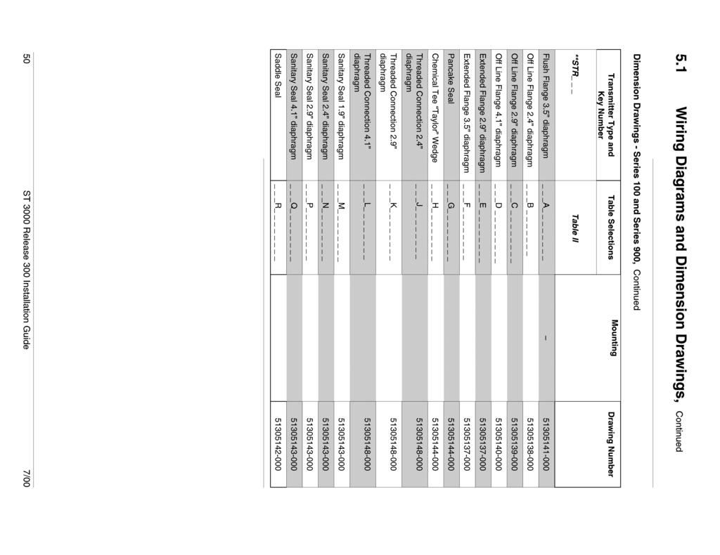
50

51
52
53
54
55
56
57
58
59
60
61
62
63
64
65
66
67
68
69
70
71
72
73
74
75
76
77
78
79
80
81
82
83
84
85
86
87
88
89
90

91
92
93
94
95
96
97
98
99
100
101
102
103
104
105
106
107
108
109
110
111
112
113
114
115
116
117
118
119
120
121
122
123
124

125
126
127
128
129
130
131
132
133
134
135
136
137
138
139

140
141
142
143
144

145
146
147
148
149
150
151
152
153

154
155
156
157
158
159
160
161
162
163
164
165
166
167
168
169
170 ST 3000 Smart Pressure Transmitter, Release 300 and Smart Communicator Model STS ST /02 Addendum (to Installation Guide 34-ST-33-39C) Overview ATEX Directive 94/6/EC The ATEX Directive 94/6/EC is a European CE Mark directive concerning products that are designed for use in potentially explosive environments. This New Approach directive is based on, and is an expansion of, European Norms (EN, CENELEC standards). On June 30, 2003, the ATEX (ATmospheres EXplosibles) directive will replace directives currently in effect, and from that time, only products with the ATEX certification and with ATEX labeling will be approved for free movement in the 19 EU (European Union) and EFTA (European Free Trade Association) countries. As defined in the directive, free movement refers to: placing a product on the market, and/or placing a product into service. The ATEX Directive 94/6/EC is a living (set of) document(s), subject to further change and refinement, whose details are beyond the scope of this addendum. Further information can be obtained in the Official Journal of the European Communities No L100/1, and in related publications such as Guidelines on the Application of Directive 94/9/EC. Both of these items are available at: Products that have been previously certified under the EN and CENELEC European Norms, and which comply fully with all standards in the New Approach directive have, by application, received certification under ATEX Directive 94/6/EC. The Honeywell ST3000 Smart Pressure Transmitter is now ATEX certified, and all units manufactured currently and in the future will include labeling that includes all markings required under the ATEX directive. Inclusions To ensure that all required information will be available to the user, the following items are include with this Addendum for reference: 1. Declaration of Conformity ATEX CE0344 (Honeywell document number Revision A). 2. Certificate of Manufacturer II G EEx na ATEX CE (Honeywell document number Revision A). 8/02 34-ST (Addendum to 33-ST-33-39C) 1 of 12
171 Purpose and Content of this Addendum This Addendum includes information required under the ATEX Directive regarding: 1. The appearance and meaning of each certification mark (CE Mark) that appears on the label(s) affixed to the product. 2. Instructions for installation and use of the product. Information required for use of this product is given in: 34-ST-25-14B - ST 3000 Smart Transmitter Release 300 and Smart Field Communicator Model STS103, and Installation information is given in 34-ST-33-39C - ST 3000 Smart Transmitter Release 300 and Smart Field Communicator Model STS103 Installation Guide, of which this Addendum is a part. Details regarding certification marks that appear in labeling for this product are given in this addendum. Attention The publications cited above and the functioning and construction (except for labeling) of the devices described therein are essentially unchanged. The purpose of this addendum is to provide details the purpose and appearance of the labels attached to each device under ATEX Directive 94/6/EC. Attention Before installing the equipment in a potentially explosive atmosphere, please read the information provided in this Addendum, which supports the ATEX certifications for this product. CE Conformity The ST 3000 Smart Pressure Transmitter is in conformity with the protection requirements of the following European Council Directives: 94/9/EC, the Explosive Atmospheres (ATEX) Directive, 89/336/EEC, the Electromagnetic Compatibility (EMC) Directive, and the Pressure Equipment (PED) directive. In conformity with the ATEX directive, the CE mark on the certification nameplate includes the Notified Body identification number 0344 (KEMA 01ATEXQ3199) adjacent to the EC Type Examination Certificate number. In conformity with the Pressure Equipment Directive, models rated greater than 200 bar (2,900 psi) have an additional CE mark applied to the meter body data plate in accordance with 97/23/EC, Article 15. Models rated at less than 200 bar have no CE mark on the meter body data plate per 97/23/EC, Article 3, Section 3. Deviation from the installation conditions in this manual may invalidate this product s conformity with the Explosive Atmospheres, Pressure Equipment, and EMC Directives. Conformity of this product with any other CE Mark Directive(s) shall not be assumed. 2 of ST (Addendum to 33-ST-33-39C) 8/02

172 Marking, ATEX Directive Honeywell s Model ST 3000 Smart Pressure Transmitter, with the following nameplates attached, has been certified to comply with Directive 94/9/EC of the European Parliament and the Council as published in the Official Journal of the European Communities No. L 100/1 on 19-April The following information is provided as part of the labeling of the transmitter: Name and Address of the manufacturer: Honeywell, Phoenix, AZ USA. Notified Body identification: KEMA Quality B.V., Arnhem, the Netherlands For complete model number, see the Model Selection Guide for the particular model of pressure transmitter. The serial number of the transmitter is located on the Meter Body data-plate. The first two digits of the serial number identify the year (02) and the second two digits identify the week of the year (23); for example, 0223xxxxxxxx indicates that the product was manufactured in 2002, in the 23 rd week. 8/02 34-ST (Addendum to 33-ST-33-39C) 3 of 12
173 Specific Parameters for Intrinsic Safety Field wiring terminals, (+, ): Without local analog meter, ME: With local analog meter, ME: With local smart digital meter, SM: Ui = 30 V, Ii = 100 ma, Pi = 1.2 W Ci = 4.2 nf, Ri = 0, Li = 0 Ci = 4.2 nf, Ri = 0, Li = 150 µh Ci = 4.2 nf, Ri = 0, Li = 0 Special conditions for safe use, Intrinsic Safety (X) The pressure transmitter is an intrinsically safe apparatus that can be installed in potentially explosive atmospheres. The power terminals (+, -) must be connected only to a certified associated intrinsically safe apparatus. The electrical parameters (U, I, and P) of the associated apparatus connected to the power terminals (+, -) must not exceed the following values: Ui 30V Ii 100 ma Pi 1,2 W Ambient temperature: - 50ºC to 93ºC NOTE: -50ºC to 93ºC is the certification and Operative Limits for the product family. Refer to individual Specification Sheets for the standard Rated Condition ambient limits for a particular model that, as shown on the data-plate and certification nameplate, may be less than the certification limits. Temperature classifications: IS (ia) 4 20 ma / DE T4 up to Ta 93ºC T5 up to Ta 85ºC Flameproof (d) T5 up to Ta 93ºC T6 up to Ta 78ºC T6 up to Ta 78ºC Enclosure classification: IP 66/67, Type 4X Specific Parameters for Flameproof Installation Power supply to field wiring terminals, (+, ): Ucc 42 V Output Signal: 4 20 ma Special conditions for safe use, Flameproof Installation Ambient operating temperature: - 50 to 93ºC NOTE: -50ºC to 93ºC is the certification and Operative Limits for the product family. Refer to individual Specification Sheets for the standard Rated Condition ambient limits for a particular model that, as shown on the data-plate and certification nameplate, may be less than the certification limits. 4 of ST (Addendum to 33-ST-33-39C) 8/02
174 Specific Parameters for Non-Sparking Zone 2 Installation (Honeywell certified) Supply Voltage: Supply Current: Ambient Temperate Limits: Temperature Classification: Vdc 23 ma - 50 o C to 93 o C T6 at Ta 65 o C T5 at Ta 80 o C T4 at Ta 93 o C Special Conditions for Safe Use, Non-Sparking Zone 2 Installation (Honeywell certified) The installation of this equipment in Zone 2 hazardous areas must comply with VDE specification 0165, IEC , EN and/or valid national standards for installation and operation. Before commissioning of this equipment, it must be verified that the power supply voltage cannot exceed the 42 Vdc maximum for 4-20 ma analog and DE equipment. The electronic assemblies in these units are non-repairable items and if faulty must be replaced. The electrical power supply must be switched off before any replacement and during any time that the wiring terminations are being connected or disconnected. 8/02 34-ST (Addendum to 33-ST-33-39C) 5 of 12
175 6 of ST (Addendum to 33-ST-33-39C) 8/02
176 , Revision A DECLARATION OF CONFORMITY ATEX 0344 We declare under our sole responsibility that the following products, ST 3000 Smart Pressure Transmitters, Series 100 and 900, Release 300 (per attached list) to which this declaration relates, are in conformity with the protection requirements of Council Directive: 94/9/EC (ATEX Directive) on the approximation of the laws of the Member States concerning equipment and protective systems intended for use in potentially explosive atmospheres, and 89/336/EEC (EMC Directive) as amended by 92/31/EEC and 93/68/EEC on the approximation of the laws of the Member States relating to Electromagnetic Compatibility. The models covered by this Declaration and evidence of conformity with the ATEX Directive are shown on the attached list. Conformity to the ATEX Directive is in accordance with the following European standards. EN EN EN EN Electrical Apparatus for Potentially Explosive Atmospheres - General Requirements Electrical Apparatus for Potentially Explosive Atmospheres - Flameproof Enclosure d Electrical Apparatus for Potentially Explosive Atmospheres - Intrinsic Safety "i" Special Requirements for Construction, Test and Marking of Electrical Apparatus of Equipment Group II, Category 1 G Manufacturer: Honeywell International Inc Black Canyon Highway Phoenix, Arizona USA The authorized signatory to this declaration, on behalf of the manufacturer, and the Responsible Person is identified below. Honeywell International Inc. Industrial Measurement & Control 1100 Virginia Drive Fort Washington, PA USA Frederick M. Kent Standards & Approvals Engineer, (ATEX Authorized Person) Issue Date: 19 August, /02 34-ST (Addendum to 33-ST-33-39C) 7 of 12
177 ST3000, R300 Pressure Transmitters Certificate Protection Model Description LCIE 02 ATEX 6099 II 2 G, EEx d IIC ST - _- -3D Smart Pressure Transmitter, 4-20 ma / DE / HART / Fieldbus LCIE 02 ATEX 6100X II 2 G, EEx ia IIC ST - _-HC -3S Smart Pressure Transmitter, 4-20 ma / HART LCIE 02 ATEX 6101X II 1 G, EEx ia IIC ST - _-FF -3S Smart Pressure Transmitter, Fieldbus Model Series Description STA Absolute Pressure Transmitter STA Absolute Pressure Transmitter STD Differential Pressure Transmitter STD Differential Pressure Transmitter STD Differential Pressure Transmitter STD Differential Pressure Transmitter STD Differential Pressure Transmitter STF Flange Mounted Liquid Level Transmitter STF12F 100 Flange Mounted Liquid Level Transmitter STF Flange Mounted Liquid Level Transmitter STF13F 100 Flange Mounted Liquid Level Transmitter STF14F 100 Flange Mounted Liquid Level Transmitter STF14T 100 High Temperature Flange Mounted Pressure Transmitter STG Gauge Pressure Transmitter STG14L 100 Gauge Pressure Transmitter STG14T 100 High Temperature Gauge Pressure Transmitter STG Gauge Pressure Transmitter STG17L 100 Gauge Pressure Transmitter STG Gauge Pressure Transmitter STG18L 100 Gauge Pressure Transmitter STR12D 100 Remote Diaphragm Seal Pressure Transmitter STR13D 100 Remote Diaphragm Seal Pressure Transmitter STR14A 100 Remote Diaphragm Seal Pressure Transmitter STR14G 100 Remote Diaphragm Seal Pressure Transmitter STR17G 100 Remote Diaphragm Seal Pressure Transmitter STA Gauge and Absolute Pressure Transmitter STA Gauge and Absolute Pressure Transmitter STD Differential Pressure Transmitter STD Differential Pressure Transmitter STD Differential Pressure Transmitter STF Flange Mounted Liquid Level Transmitter STF Flange Mounted Liquid Level Transmitter STF92F 900 Flange Mounted Liquid Level Transmitter STF Flange Mounted Liquid Level Transmitter STF93F 900 Flange Mounted Liquid Level Transmitter STG19L 900 High Pressure Gauge Transmitter STG93P 900 Flush Mount Gauge Pressure Transmitter STG Gauge and Absolute Pressure Transmitter 8 of ST (Addendum to 33-ST-33-39C) 8/02
178 Model Series Description STG94L 900 In-Line Gauge Pressure Transmitter STG Gauge and Absolute Pressure Transmitter STG97L 900 In-Line Gauge Pressure Transmitter STG98L 900 In-Line Gauge Pressure Transmitter STG99L 900 High Pressure Gauge Transmitter STR93D 900 Remote Diaphragm Seal Pressure Transmitter STR94G 900 Remote Diaphragm Seal Pressure Transmitter 8/02 34-ST (Addendum to 33-ST-33-39C) 9 of 12
179 10 of ST (Addendum to 33-ST-33-39C) 8/02
180 Certificate of Manufacturer II 3 G EEx na IIC ATEX , Revision A This certificate applies to the following equipment: ST 3000 Smart Pressure Transmitters, Series 100 and 900, Release 100 and 900, 4-20 ma, DE, HART, and FOUNDATION TM Fieldbus (per attached list) This equipment has no arcing or sparking parts and no ignition-capable hot surfaces, and therefore conforms to Clause of VDE 0165/2.91, IEC , and EN for operation in Zone 2 hazardous areas providing that the following conditions are observed. The equipment contains no intrinsically safe or energylimiting components. The listed equipment are 2-wire devices that receive their power and signal carrier from the same 4-20 ma signal current or Fieldbus supply. In normal operation, the maximum current supply is 23 ma for 4-20 ma analog, DE or HART, and 260 ma for Fieldbus. Conditions for the application of the above equipment in Zone 2 hazardous areas: 1. The installation of this equipment in Zone 2 hazardous areas must comply with VDE specification 0165, IEC , EN and/or valid national standards for installation and operation. 2. Before commissioning this equipment, it must be verified that the power supply voltage cannot exceed the 42 Vdc maximum for 4-20 ma analog, DE and HART equipment, and 32 Vdc for Fieldbus equipment. 3. The electronic assemblies in these units are non-repairable items and if faulty, must be replaced. The electrical power supply must be switched off before any replacement and during any time that the wiring terminations are being connected or disconnected. 4. The technical data supplied by the manufacturer must be adhered to. Specifications for Use in Zone ma / DE / HART Fieldbus Supply Voltage: Vdc 9 32 Vdc Supply Current: 23 ma 260 ma Ambient temperature limits: 50 to 93ºC Temperature Classification: T6 at Ta 65ºC T5 at Ta 80ºC T4 at Ta 93ºC Manufacturer: Honeywell International Inc Black Canyon Highway Phoenix, Arizona USA Honeywell International Inc. Industrial Measurement & Control 1100 Virginia Drive Fort Washington, PA USA Frederick M. Kent Standards & Approvals Engineer, (ATEX Authorized Person) Issue Date: 16 August, /02 34-ST (Addendum to 33-ST-33-39C) 11 of 12
181 ST3000, R300 Pressure Transmitters Model Series Description STA Absolute Pressure Transmitter STA Absolute Pressure Transmitter STD Differential Pressure Transmitter STD Differential Pressure Transmitter STD Differential Pressure Transmitter STD Differential Pressure Transmitter STD Differential Pressure Transmitter STF Flange Mounted Liquid Level Transmitter STF12F 100 Flange Mounted Liquid Level Transmitter STF Flange Mounted Liquid Level Transmitter STF13F 100 Flange Mounted Liquid Level Transmitter STF14F 100 Flange Mounted Liquid Level Transmitter STF14T 100 High Temperature Pressure Transmitter STG Gage Pressure Transmitter STG14L 100 Gage Pressure Transmitter STG14T 100 High Temperature Pressure Transmitter STG Gage Pressure Transmitter STG17L 100 Gage Pressure Transmitter STG Gage Pressure Transmitter STG18L 100 Gage Pressure Transmitter STR12D 100 Remote Diaphragm Seal Pressure Transmitter STR13D 100 Remote Diaphragm Seal Pressure Transmitter STR14A 100 Remote Diaphragm Seal Pressure Transmitter STR14G 100 Remote Diaphragm Seal Pressure Transmitter STR17G 100 Remote Diaphragm Seal Pressure Transmitter STA Gage and Absolute Pressure Transmitter STA Gage and Absolute Pressure Transmitter STD Differential Pressure Transmitter STD Differential Pressure Transmitter STD Differential Pressure Transmitter STF Flange Mounted Liquid Level Transmitter STF Flange Mounted Liquid Level Transmitter STF92F 900 Flange Mounted Liquid Level Transmitter STF Flange Mounted Liquid Level Transmitter STF93F 900 Flange Mounted Liquid Level Transmitter STG19L 900 High Pressure Gauge Transmitter STG93P 900 Flush Mount Gage Pressure Transmitter STG Gauge and Absolute Pressure Transmitter STG94L 900 In-Line Gage Pressure Transmitter STG Gauge and Absolute Pressure Transmitter STG97L 900 In-Line Gauge Pressure Transmitter STG98L 900 In-Line Gauge Pressure Transmitter STG99L 900 High Pressure Gauge Pressure Transmitter STR93D 900 Remote Diaphragm Seal Pressure Transmitter STR94G 900 Remote Diaphragm Seal Pressure Transmitter 12 of ST (Addendum to 33-ST-33-39C) 8/02
182
183
184
185


186 Honeywell M9484 AND M9494 MODUTROL MOTORS ARE LOW VOLTAGE, REVERSING PROPORTIONAL CONTROL ACTUATORS FOR VALVES, DAMPERS AND AUXIL- IARY EQUIPMENT. THEY ARE ESPECIALLY DE- SIGNED FORCOMMERCIALOR INDUSTRIALOILOR GAS BURNER CONTROL SYSTEMS. i Replace M941 motors. 0 Oil immersed motor and gear train for reliable performance and long life. 0 Wiring box provides NEMA 3 weather protection. 0 Actuator motor and circuitry operate from 24 volts AC. Models available with factory installed transformer, or internal transformer can be field added. Cl Quick-connect terminals standard - screw terminal adapter available. Cl Adapter bracket for matching shaft height of older motors is standard with replacement motors. 0 Field adjustable stroke (90 to 160 ) models available. Nominal timing of 30 seconds for 90 and 60 seconds for 160 stroke is standard. Other timings are available. 0 Die-cast magnesium housing., Available accessories include valve and damper linkages, explosion proof housing, and auxiliary switches. 0 Field addable interface modules can be mounted in wiring box to upgrade actuator to Series 70 (electronic) control. i Models available with tapped output shaft. 0 M9481, M9484 rated for 150 lb.-in. torque at standard timings. cl M9491, M9494 rated for 300 lb.-in. torque at 2 or 4 minute timings for 160 stroke. S.M. Form Number l Rev. Inc. 1990
187 -...l , ,.., : :.:...:...: :.:.. _._..... :.:..... :.:.:..._...,.,.,...,.,.,.,.,.,.,.,.,.,.,.,.,.,.,.,.,.,., STANDARD MODELS control Type T TTLix Letter 94 is Series 90 ~~ I Power Rating 8 is high torque 150 lb.-in. at standard timing 9 is high torque 300 lb.-in.at 2 or 4 min timing Output Drive 4 is dual-ended shaft, non-spring return 1 is single-ended shaft, non-spring return D: E: F: is adjustable stroke (90 to 1 60 ) No auxiliary switches is adjustable stroke (90 to 1 60 ) 1 auxiliary switch is adjustable stroke (90 to 1 60 ) 2 auxiliary switches NOTE: Some motors furnished to equipment manufacturers will have no adapter bracket, a single-ended shaft and/or no wiring box. CONTROLLER TYPE: Series 90 Control Circuit-135 ohm series 90 proportioning controller. Series 90 high or low limit controller with manual minimum position potentiometer (with a combined total resistance of up to 500 ohms) may also be used in the control circuit. MOTOR ROTATION: Normally closeda. The closed position is the limit of counterclockwise rotation as viewed from the power end of the motor. See Fig 2. Motor opens clockwise (as viewed from the power end). Motors are shipped in the closed position. ELECTRICAL RATINGS: VOLTAGE POWER CURRENT CONSUMP- DRAW (A) TfON (W) Without Transformer With internal Transformer STROKE: Field adjustable from 90 to 160. Start position of shaft changes with adjustment of stroke. (Midpoint of stroke remains fixed as stroke is adjusted, as shown in Fig. 2.) Stroke is adjusted by means of cams located in wiring compartment. (See Stroke Setting Procedure.) Motors are shipped with stroke set at 90. DEAD WEIGHT LOAD ON SHAFT: Power or Auxiliary End-200 lb. [90.8 kg] maximum. Maximum Combined Load-300 lb. [136 kg]. AMBIENT TEMPERATURE RATINGS: Maximum-150 F [66 25% duty cycle. Minimum-minus 40 F [-40 C]. CRANKSHAFT: 318 inch [9.5mm] square M9484, M9494 have double-ended shaft. M9481, M9491 have single-ended shaft. athe normal position is the position the motor will assume with controller disconnected. ::::::::::::::::::::::::::::::::::::::::::::::::::::::::::::::::::::::::... _......: L.. ~~~~~~~~:~~I~~~~CYJ~~~:R.~~~~~~~~~~~~~ _..I _...i _ i... _....:.~~ _~~::.~ i i _. :_~~r~_ :.~.~.~.~.~.~.~.~.~.~.~.~.~.~.~.~.~.~.~.~.~.~.~.~.~.~.:.:.:.:.:.:.:.:.:.:.:.:.:.:.:.,.._...:.,.,.~_.:_:_._:_):_:_:.:.:.~.~.:.~.:.~.:.~.~.~.~.~.~.~.~.~.~.~.~.~.~.~.~.~.~.~.~.~.~.~.~.~.~.~.~.~.~.~.~.~~.~.~~.~.~~~~ t_~_._._._._._._._ WHEN PURCHASING REPLACEMENT AND MODERNIZATION PRODUCTS FROM YOUR AUTHORIZED DISTRIBUTOR, REFER TO THE TRADELINE CATALOG OR PRICE SHEETS FOR COMPLETE ORDERING NUMBER. IF YOU HAVE ADDITIONAL QUESTIONS, NEED FURTHER INFORMATION, OR WOULD LIKE TO COMMENT ON OUR PRODUCTS OR SERVICES, PLEASE WRITE OR PHONE: YOUR LOCAL HONEYWELL RESIDENTIAL AND BUILDING CONTROLS SALES OFFICE (CHECK WHITE PAGES OF PHONE DIRECTORY). RESlDENTlAL AND BUILDING CONTROLS CUSTOMER SERVICE HONEYWELL INC., 1885 DOUGLAS DRIVE NORTH MINNEAPOLIS, MINNESOTA (612) (IN CANADA-HONEYWELL LIMITED/HONEYWELL LIMITEE, 740 ELLESMERE ROAD, SCARBOROUGH, ONTARIO Ml P 2V9) INTERNATfONAL SALES AND SERVICE OFFICES IN ALL PRINCIPAL CITIES OF THE WORLD. 2

188 AUXILIARY SWITCH RATINGS (amperes): M94XXE has 1 spdt switch. M94XXF has 2 spdt switches. ONE CONTACT a 120v 240v Full Load Locked Rotor a4o VA pilot duty, Vat on opposite contact. DIMENSIONS: See Fig. 1. UNDERWRITERS LABORATORIES INC. LISTED File No. E4436; Guide No. XAPX. CANADIAN STANDARDS ASSOCIATION CERTIFIED: General Listing File No. LR1620,400-E-) U STROKE STROKE RUNNING BREAKAWtY 15 set 30 set [17.0] 30 set 1 min 150 [17.0] 300 [34.0] 1.2 min 1 2,4 mind abreakaway torque is the maximum torque available to overcome occasional large loads such as a seized damper or valve. MOTOR MUST NOT BE USED CONTINUOUSLY AT THIS RATING. bstalling of 2,4 min motor will damage motor. ACCESSORIES: ES Explosion-proof Housing-Encloses motor for use in explosive atmospheres. Not for use with Q601, Q618, and Q455 Linkages. Order from Nelson Electric Co. Requires Honeywell 7617DM Coupling. Q607 External Auxiliary Switch-Controls auxiliary equipment as a function of motor position. Q605 Damper Linkage-Connects motor to damper. INCLUDES MOTOR CRANK ARM Linkage-Connects Modutrol motor to water or steam valve. Q601 Bracket and Linkage Assembly-Connects Modutrol motor to water or steam valve. Ql OOA,B Linkage-Connects Modutrol motor to butterfly valve. Requires adapter bracket packed with motor. Q209E,F Potentiometer-Limits minimum position of motor. Q68 Dual Control Potentiometer-Controls 1 through 9 additional motors. Q181 Auxiliary Potentiometer-Controls 1 or 2 additional motors A Motor Crank Arm-Infinitely adjustable crank arm. Approximately 0.75 inches shorter than the 4074ELY crank arm, can rotate through downward position and clear base of motor without requiring use of adapter bracket A Screw Terminal Adapter-converts the standard quick-connect terminals to screws terminals. Transformers-mounted internally, provide 24 Vat power to motor JA-24 Vat; 50/60 Hz (for electrical isolation) EA-120 Vat; Hz GA-220 Vat; Hz Al-120/208/240 Vat; Hz. Q7130A-Interface Module with selectable voltage ranges (4-7 Vdc, 6-9 Vdc, and Vdc). Adapts motor to M71 XX function. Q7230A-Interface Module, selectable voltage or current control, with adjustable null and span. Adapts motor to M72XX function; 4 to 20 ma or 2 to 10 Vdc. Q7330A-Interface Module, for W936 economizer applications. Adapts motor to M73XX function. Q7630A-Interface Module, 3-wire Vdc control with minimum position capability. Adapts motor to M76XX function. 4074BYK-Control up to 6 M9lXX motors in unison from one Series 90 controller. 4074EAU-Drive 2 or 3 M91 XX motors from a W973 Single-zone Logic Panel or W7100 Discharge Air Controller. 4074EDC-Drive one M91XX motor from a 4-20 ma Controller. 4074EED-Drive up to 4 M91 XX motors from a 4-20 ma Controller A Resistor Board-Plugs onto quick-connects in wiring box of M9lXX motor. Can be used in place of 4074BYK, EAU, EDC, or EED resistor kits (functions described above). 7616ADW Motor Crank Arm-Approximately 0.75 inches shorter than the 7616BR crank arm, can rotate through the downward position and clear base of motor without requiring use of adapter bracket. WHEN INSTALLING THIS PRODUCT Read these instructions carefully. Failure to follow them could damage the product or cause a hazardous condition. 2. Checkthe ratings given in the instructions andon the product to make sure the product is suitable for your application. 3. Installer must be a trained, experienced service technician. 4. After installation is complete, check out product operation as provided in these instructions Disconnect power supply before beginning installation to prevent eiectrical shock and equipment damage. Never turn the motor shaft by hand or with a wrench-this will damage the motor. Always conduct a thorough checkout when installation is complete l
189 f [136] ADAPTER BRACKET FIG. 1-UIMtNSIUNS IN In. NOTE: M9481, M9491 do not have auxiliary shaft. All other dimensions are the same. LOCATION install the Modutrol motor in any location except where acid fumes or other deteriorating vapors might attack the metal parts, or in atmospheres of escaping gas or the explosive vaporsin excessive salt environments, mounting base and screws should be zincorcadmium plated, not stainless steel or brass: Use the A adapter bracket for mounting on these surfaces. Allow enough clearance for installing accessories and servicing the motor when selecting a location. See Fig. 1. If located outdoors, mount upright and use liquid-tight con- duit connectors with wiring box to provide NEMA 3 weather protection. MOUNTtNG Always install motors with the crankshaft horizontal. Mounting flanges extending from the bottom of the motor housing are drilled for l/4 inch [6.4mm] machine screws or bolts. Motors are shipped from the factory in closed position (at the limit of counterclockwise rotation as viewed from the power end of the motor, as shown in Fig. 2) with the stroke set at 90. 4
190 NON SPRING RETURN MOTORS FIG. 2-LIMITS OF MOTOR ROTATION. E373C ADAPTER BRACKET The220738A Adaptor Bracket, positioned between the motor and the equipment, raises the shaft height ptthe- M9484 motor by 0.75 inch to match that of the M941 motor. This is required on all valve linkage applications, Q607 External Auxiliary Switch applications, and on some damper linkage applications (either to provide clearance for the crank arm to rotate through the downward position, or to allow the damper linkage to reach the shaft). To mount the motor with the bracket: 1. Mount the bracket to the equipment with existing or standard bolts. 2. Mount the motor to the bracket using the bolts provided into the threaded holes of the bracket (see Fig. 3). For valve linkage applications, the bracket should first be mounted to the linkage (see Fig. 4). The bracket then provides a convenient base on which the motor can be positioned. After the motor shaft is aligned to the linkage, it can then be attached to the bracket with the 4 bolts provided. These bolts go through the inner set of holes in the motor flanae and into the threaded holes of the bracket. BOLTS PROVIDED (4) n1 #12 OR l/4 ZINC PLATED MACHINE SCREWS OR BOLTS M 3076 FIG. MOUNTING MOTOR WITH A ADAPTER BRACKET. The bracket is first mounted to the equipmel with standard bolts. The motor is then mounted to the bracket using the bolts provided with the bracket, which thread into the threaded bracket holes. DAMPER LINKAGES A A Adapter Bracket is packed with replacement motors. Use of this bracket is optional for many damper applications but may be needed in damper applications requiring the crank arm to rotate through the bottom plane of the actuator. If the bracket is not used in a replacement application, the damper linkage will have to be adjusted to the new shaft position. The motor comes without a crank arm. The crank arm is included in the Q605 linkage or may be ordered separately (see Accessories). For detailed instructions on the assembly of specific linkages, refer to the instruction sheet packed with each linkage. In general, however, check the following points of operation when installing a motor and linkage. 1. Linkages for valves and louver type dampers should be adjusted so that the damper or valve moves through only the maximum required distance when the motor moves through its full stroke. 2. With modulating control, maximum damper opening should be no more than 60. Little additional airflow is provided beyond this point. 3. The motor must be stopped at the end of its stroke by the limit switch and must not be stalled by the damper or valve. The motor will be damaged if it is not permitted to complete its full stroke l
191 Y BOLTS PROVIDED (4) WIRING BOX MOTOR M 31% MACHINE SCREWS OR BOLTS. LTS SECURING BRACKET TO LINKAGE. TIGHTEN AFTER SECURING MOTOR TO THE BRACKET USING FOUR BOLTS PROVIDED. FIG. 4-MOTOR MOUNTING ON VALVE LINKAGE,. 4. Do not exceed the motor ratings in any installation. 5. Do not turn motor shaft manually or with a wrenchthis will damage the motor. VALVE LINKAGES The A Mounting Bracket must be used with the Ql 00, Q601 and Q618 linkages in all valve applications. WIRING Disconnect power supply before wiring to prevent electrical shock or equipment damage. All wiring must agree with applicable codes, ordinances, and regulations. A transformer is required to supply 24 Vat power to the motor. Make sure that the power requirements stamped on the motor correspond to the characteristics of the power supply. Figs. 5 and 6 show internal schematics. The motor terminals are quick-connects located on top of theprintedcircuit boardshown in Fig.7.Ascrewterminal adapter is standard on all Trade models and also may be added to all models. Access to the wiring compartment is gained byremovingthe4screws inthetoppf the wiring box and lifting off the cover. WIRING BOX When used with liquid-tight conduit connectors, the wiring box provides NEMA 3 weather protection for the motor. The box also provides knockouts for wiring conduits and encloses terminals. The wiring box, standard with replacement motors, is required for housing an internal transformer, internal auxiliary switches or Series 70 Interface Modules. 6
192 A BLUE LEAD A YELLOW LEAD 1 A I CLOSE LIMIT REDLEAD 2 n n1 n2 WIRING SHOULD BE NEC CLASS 1 UNLESS POWER SUPPLY MEETS CLASS 2 REQUIREMENTS. TAPE UNUSED LEADS. MAKE CERTAIN THE CURRENT DRAW OF THE EXTERNAL CIRCUIT IS LESS THAN CONTACT RATING OF SWITCH. ON TWO-SWITCH MOTORS SECOND SWITCH HAS BLACK LEADS WITH BLUE, YELLOW. AND RED TRACERS. DIRECTION OF MOTOR TRAVEL AS VIEWED FROM POWER END. M 254 & CONNECT 24V POWER TO Tl-T2 TERMINALS ONLY. DO NOT CONNECT POWER SUPPLY TO CONTROLLER TERMINALS. PROVIDE DISCONNECT MEANS AND OVERLOAD PROTECTION AS REQUIRED. n 3 TURN LIMIT POT FULL CLOCKWISE~FOR 160 STROKE, FULL COUNTERCLOCKWISEr?FOR 90 STROKE. I FIG. 5-lNTERNAL WIRING OF An9494 MODUTROL MOTORS. FIG. 6-AUXILIARY SWITCH INTERNAL WIRING. MINIMUM :ztlon I STROKE ADJUSl CAMS (YELLOW) INNER AUXILIARY INNER AUXILIARY SWITCH CAM (BLUE) OUTER AUXILIARY SWITCH CAM (RED) * OUTER AUXILIARY STROKE POT NOTE: FEATURES AVAILABLE ON SOME MODELS ONLY. M ml/\ FIG. 7-TERMINALS AND ADJUSTMENTS l
193 AUXILIARY SWITCH CONNECTIONS supplies to de-energize the The M9484E has 1 internal auxiliary switch. The switch wires are color-coded as follows: solid yellow-normally closed (N.C.); solid red-common (COM.); solid blue-normally open (N.O.). The M9484F has 2 internal auxiliary switches which may be used to prove low fire and high fire positions. 1. To prove low fire use red (common) and yellow wires connected to outer (left) switch. This switch makes red to yellow and breaks red to blue as motor closes. 2. Wires connected to the inner (right) switch are black with colored tracers. To prove high fire, use red tracer (common) and blue tracer wires. The right switch makes red tracer to blue tracer and breaks red tracer to yellow tracer as motor opens. Color coding and switching action are tabulated below to aid the installer. SWITCH/CAM COLOR-CODING: SWITCH LOCATlON Left Right CAM ASSEMBLY LOCATIONa Outer Inner aviewed from power end of motor. bsee Fig. 6. TABLE 1 CAM COLOR CODE Red Blue SWITCH WIRESb COLOR DESIGNATION Solid Yellow Normally Closed (N.C.) Solid Red Common (COM.) Solid Blue Normally Open (N.O.) Yellow Tracer Normally Closed (N.C.) Red Tracer Common (COM.) Blue Tracer Normally Open (N.O.) SWITCHING ACTION: SWITCH LOCATIONa Left Right NORMAL FUNCTION Proves Low Fire Position Proves High Fire Position aviewed from power end of motor. bsee Fig. 9 TABLE 2 CAM MOTOR MAKES BREAKES POSITIONb POSITION Red Red High portion of cam Closing to to not in Contact Yellow Blue with Cam follower. Red Tracer Red Tracer High portion of cam Opening to to in Contact Blue Tracer Yellow Tracer with Cam follower. STROKE SEl-lING On M94XXD,E,F motors, stroke is field adjustable and can be set from 90 to 160. Motors are shipped in 90 position. In order to set stroke, both mechanical and electrical adjustments are required. The mechanical adjustments (cams) establish the full open (clockwise, n as viewed from the power end) and full closed (counterclockwise 0 ) positions of the motor shaft. The electrical adjustment (trim pot) provides sufficient total stroke angle to ensure that cams will actuate both limit switches. STROKE SETTING PROCEDURE See Fig. 8. Detach linkage from motor before adjusting stroke. BEFORE SETTING STROKE: 1. Remove top cover from motor. 2. Disconnect controller from motor. 3. Connect R,B,W terminals on 135 ohm potentiometer (Q209 or S963) to matching terminals on motor. SETTING 160 STROKE (Fig. 8): 1. Turn stroke pot fully clockwise f7. 2. Drive motor to mid-position using 135 ohm pot (Q209 or S963), or by jumpering B-R-W. 3. Insert l/8 in. screwdriver blade into slot on inner yellow cam and MOVE TOP OF SCREWDRIVER as far as possible counterclockwise n (viewed from power end). Repeat in successive cam slots until inner cam is against counterclockwise 0 stop. 8
194 MOVE SCREWDRIVER AT TOP ONLY TO ADJUST CAM: l/8 IN. STRAIGHT BLADE SCREWDRIVER OUTER STROKE ADJUST CAMS OUTER CAM RY SWITCH CAMS A 1 A POWER SUPPLY. PROVIDE DISCONNECT MEANS AND OVERLOAD PROTECTION AS REQUIRED. 2 TRANSFORMER MAY BE EXTERNAL OR INTERNAL. NOTE: CAMS ARE OFFSET M 3,3A PROVIDE BETTER VIEW OF BACK CAM. M305 FIG. 8-STROKE ADJUSTMENT SETUP. l/8 IN. STRAIGHT-BLADE SCREWDRIVER STROKE ADJUST CAMS (YELLOW) RIGHT/INNER INNER AUXILIARY CAM (BLUE) OUTER AUXILIARY CAM (RED) A 1 A 2 POWER SUPPLY. PROVIDE DISCONNECT MEANS AND OVERLOAD PROTECTION AS REOUIRED. TRANSFORMER MAY BE EXTERNAL OR INTERNAL. M 315c OTOR CLOSE POWER END NOTE: CAMS ARE OFFSET VERTICALLY TO PROVIDE BETTER VIEW OF BACK CAM. M 3060 FIG. O-AUXILIARY SWITCH ADJUSTMENT SETUP l
195 IMPORTANT Set cams by moving top of screwdriver only. Pressing screwdriver against sides of cam slots could cause damage to motor end switches. 4. Insert l/8 in. screwdriver blade into slot on outer yellow cam and MOVE TOP OF SCREWDRIVER as far as possible clockwise n. Repeat in successive cam slots until outer cam is against clockwise q stop. NOTE: Excessive force will damage cam stop on hub. 5. Check motor stroke before connecting linkage. 6. Disconnect 135 ohm pot, reconnect controller, replace top cover on motor. 7. Attach linkage to motor. SETTING 90 STROKE (Fig. 8): 1. Turn stroke pot fully counterclockwise Drive motor to mid-position, using 135 ohm pot (Q209 or S963), or by jumpering B-R-W. 3. Insert l/8 in. screwdriver into slot on inner yellow cam and MOVE TOP OF SCREWDRIVER as far as possible clockwise q (viewed from power end). Repeat in successive cam slots until inner cam is against clockwise stop. NOTE: Excessive force will damage cam stop on hub. 4. Insert l/8 in. screwdriver blade into slot on outer yellow cam and MOVE TOP OF SCREWDRIVER as far as possible counterclockwise c. Repeat in successive cam slots until outer cam is against counterclockwise stop. NOTE: Excessive force will damage cam stop on hub. 5. Check motor stroke before connecting linkage. 6. Disconnect 135 ohm pot, reconnect controller, replace top cover on motor. 7. Attach linkage to motor. AUXILIARY SWITCHES The auxiliary switches in M9484E,F motors are actuated by adjustable cams. The cams are mounted on the motor shaft at the power end of the motor. The settings of the cams determine the point in motor shaft rotation at which the auxiliary equipment will be switched on or off. These cams can be set to actuate switches at any angle within the stroke of the motor. Also each cam provides a fast rise portion for switching (1 o differential) and a slow rise portion for slow switching (10 differential). Switching action and color coding are shown in Tables 1 and 2 on page 8. Motors with factory added auxiliary switches are shipped in the closed position (counterclockwise fi, as viewed from power end) with auxiliary cams set to actuate switches 30 from the closed position, and to provide 1 differential. Wiih motor in closed (full counterclockwise r\ ) position, auxiliary switch breaks R-B. IMPORTANT Do not turn motor shaft by hand or with a wrench as damage to the gear train and circuit board stroke limit contacts will result. AUXIUARY SWlTCH SElllNG PROCEDURE (Fig. 9) 1. Removetopcoverfrom motorto gain access to motor terminals and cam adjustments. 2. Disconnect controller from motor and connect 135 ohm manual potentiometer with R-W-B terminals on pot connected to corresponding terminals on motor (Fig. 9). 3. Adjust 135 ohm pot so that motor shaft turns to position where auxiliary equipment is to be switched. 4. Insert a l/8 in., straight-blade screwdriver into slot on cam associated with selected auxiliary switch. The inner (blue) cam actuates the inner (right) switch, the outer (red) cam actuates the outer (left) switch. MOVE TOP OF SCREWDRIVER to set cams. 5. For switch differential of 1 O, check continuity of auxiliary switch R-B contacts and rotate cam as follows: a. lf contacts are open, rotate cam clockwise n until R-B contacts close. b. lf contacts are closed, rotate cam counterclockwise c until R-B contacts open. 6. For switch differential of loo, check continuity of auxiliary switch R-B contacts and rotate cam as follows: a. lf contacts are open, rotate cam counterclockwise 0 until R-B contacts close. b. lf contacts are closed, rotate cam clockwise r\. until R-B contacts open. c. Final adjustment in the proper direction should be made to obtain contact make or break at the desired position. 7. Check for proper differential and switching of auxiliaryequipmentby runningmotorthroughfullstroke (inboth directions), using 135 ohm pot. Repeat adjustment if necessary. 8. Disconnect 135 ohm pot, reconnect controller, replace top cover on motor. NOTE: If differential is changed from 1 to lo, the switching action is reversed, thus: switch contacts R-B make and R-W breakon acounterclockwise (closed) rotation. MODULATlNG SERIES 90 CIRCUIT CONNECTION DIAGRAMS (Figs ) The potentiometers, one in the controller and one in the These motors are designed for use in series 90 propormotor, along with resistor network, form a bridge circuit. As tioning control circuits employing a 135 ohm series 90 long as the value of the controlled medium remains at the controller. Series 90 high or low limit controls or manual controller set point, the circuit is balanced, and the motor minimum position potentiometers may also be used in the does not run. control circuit. When the value of the controlled medium changes, the The M9484 can also be used with some electronic potentiometer wiper in the controller is moved, which controllers which provide a 4-20 ma control output. lt is unbalances the bridge circuit. This unbalance is amplified, necessary to use a resistor kii (4074EED for controlling up and energizes Triac switching to run the motor in the to 6 motors) or Q7230 Interface Module to interface to the direction necessary to correct the change in temperature 4-20 ma source. or pressure. The motor turns the feedback potentiometer The standard series 90 controller has R, W, and B to rebalance the circuit and stop the motor. terminals. As the controller reduces Rto W resistance, the motor will drive closed (CCW as viewed from the power end). 10
196 SERIES 99 CONTROLLER MOTOR OPTIONAL CONNECTIONS WITH OHM POTENTIOMETERS IN SERIES. SERIES 90 CONTROLLER - MOTOR n1 POWER SUPPLY. PROVlDE DISCONNECT MEANS AND OVERLOAD PROTECTION AS REQUIRED. SERIES 90 HIGH LIMIT CONTROL TRANSFORMER n 2 TRANSFORMER MAY BE INTERNAL OR EXTERNAL TO MOTOR. EJ74C n 1 POWER SUPPLY. PROVIDE DISCONNECT MEANS AN,, OVERLOAD PROTECTION AS REQUIRED. n 2 TRANSFORMER MAY BE INTERNAL OR EXTERNALTO MOTOR. E2rM4 IG. 1 l-motor USED WITH ASERIESSO CONTROI LER AND A SERIES 90 LOW OR HIGH LIMI CONTROL. SPDT SWITCH OR SERIES 60 CONTROLLER USED AS A 4.20 ma SOURCE SINGLE MOTOR I TRANSFORMER SLAVE MOTOR(S) 1 POWER SUPPLY. PROVIDE DISCONNECT MEANS AND OVERLOAD PROTECTION AS REOUIRED.!h 2 USE SOLID LINE CONNECTION FOR POSITIVE CLOSING TO MINIMUM POSITON. SUBSTITUTE DOTTED LINE CONNECTION FOR POSITIVE FULL CLOSURE.!I 3 TRANSFORMER MAY BE INTERNAL OR EXTERNAL TO MOTOR. M428 UP TO 4 ADDITIONAL SLAVE MOTORS (6 TOTAL, A RESISTOR (A) DEPENDS ON NUMBER OF SLAVES. SEE RESISTOR SELECT- ION CHART IN TEXT. n 2 SEE MOTOR SPECIFICATIONS FOR ACTUAL TERMINAL ARRANGEMENT. E474A ;. 12-CONNECTIONS FOR MOTOR, SERIES 90 CONTROLLER, MINIMUM POSITION PO- TENTIOMETER (ETC.). L FIG. 13-CONNECTlONS FOR MOTOR USED WITH 4 TO 20 ma CONTROL I

197 4074EED RESISTOR SELECTION CHART FOR 4-20 ma MIINIMUM OUTPUT VOLTAGE REQUIRED RESISTOR (A) MOTORS (Vdc)b (Ohms) Part No QCDHA BFAA : a BCEA BBDA a Not part of this kit, obtain separately. b These values represent the controller output voltage required to drive the motors. CHECKOUT After installation and linkage adjustment, check the entire motor and control hookup to ensure that- * The motor operates the damper or valve properly. The motor responds properly to the controller. Inspect the motor, linkage, and valve or damper to see that all mechanical connections are correct and secure. In damper installations, the pushrod should not extend more than a few inches past the ball joints. Check to see that there is adequate clearance for the linkage to move through its stroke without binding or striking other objects. Check to see that cams operate the auxiliary switches, if used, at the desired point of motor rotation. NOTE: Motors are shipped in the fully closed position (the limit of counterclockwise rotation as viewed from the power end of the motor) with the stroke set at 90. SERIES 90 MOTORS OPERATION CHECK WITH MODUTROL MOTOR DISCONNECTED FROM CONTROLLER STEP ACTION RESPONSE IF NO OR LIMITED RESPONSE 1. Apply 24 Vaca. None Open terminal B and short W to R. Motor drives closed. Proceed to Step Open terminal W and short B to R. Motor drives open. Proceed to Step Connect terminals R to B to W. Motor must drive to Mid- Proceed to Step 6. position. 5. Remove jumpers from R, B, and W. 17 to 20 Vdc. No voltage or out of range. Proceed Check voltage between B and R, to Step 7. and W and R. 6. Motor does not drive. Motor is defective. Replace motor. 7. Voltage out of range. Motor printed wiring board Replace motor. is defective. 8. Disconnect 24 Vat. Spring return motors return Spring mechanism defective to their normal mechanical -replace motor. position. NOTES: a Ensure motor transformer is sized properly. If a common transformer is used to power multiple motors, ensure power input is in phase with all motors. b Motors may operate in Series 90 or two-position control applications. However, checking voltage between terminals R to B and R to W is necessary to confirm proper operation in electronic (W973, 4 to 20 ma etc.) applications. DAMPER APPLICATION 1. Turn off power and remove wiring from the old actuator. 2. Remove crank arm from shaft of old actuator and remove the old actuator. 3. Checkto see whether or not the mounting bracket is needed. lf the linkage can reach the lowershaft position of the new actuator and if the crank arm has clearance for the needed rotation, then the bracket is not needed. Use A Adapter Bracket or A crank arm if crank arm must rotate through the bottom plane of the motor (for damper applications). 4a.If the bracket is not needed, mount the new actuator directly to the equipment and refer to the INSTALLATION, SETTlNGS&ADJUSTMENTS,andCHECKOUTsections of these instructions as needed. 4b.ffthe bracket is needed, referto the Adapter Bracket sections and see Fig. 3 as well as the INSTALLATION, SETTINGS &ADJUSTMENTS, and CHECKOUTsections of these instructions. 5. Use old mounting bolts to mount the new actuator. 6. Mountthedampercrankarmandlinkagetotheshaft of the new actuator. 8. Use the CHECKOUT procedures to test the proper adjustment of the crank arm and linkage.. VALVE APPLICATION When installing a M9484, M9494 motor in a valve application which has a QlOO, Q601 or 0618 it will be necessary to use the A Adapter Bracket provided to raisethe motorshafttothesame height asthatof theold motor. Ensure motor stroke is 160 to operate Honeywell V5011 two-way or V5013 three-way valves. Honeywell Inc. International Sates Offices in all principal cities of the world. Manufacturing in U.S.A.: 1885 Douglas Drive N. Australia, Canada, Finland, Franc%, Germany, Japan, Mexico, Netherlands, Golden Valley, MN Spain, Taiwan, United Kingdom, CANADA: 740 Ellesmere Road Lz3 Scarborough, Ontario Ml P 2V9 PRINTED IN U.S.A. QUALITY IS KEY

198 Operating Manual eztrend Easy does it! *(easy adj. UNTROUBLED: secure, prosperous, calm, peaceful, tranquil, contented, unhurried, relaxing; MANAGEABLE: simple, smooth) 43-TV GLO Issue 3 09/01 UK
199 43-TV GLO Issue 3 09/01 UK
200 7DEOHRI&RQWHQWV 7DEOHRI&RQWHQWV LLL 6DIHW\ 6\PEROV 6WDWL (OH WUL LW\,QVWDOODWLRQ&DWHJRU\ )XVHV &DEOHV :$51,1*6$1'6$)(7<35(&$87,216 'R VDQG'RQ WV +D]DUGRXV9ROWDJH 0DLQWHQDQ HDQG8QLW5HSDLU &KDSWHU,QWURGX WLRQ H=WUHQG9 'HV ULSWLRQ 6WRUDJH0HGLD 6SH LIL DWLRQV 8QLYHUVDO,QSXW DUG 8QLYHUVDO,QSXW DUGSHUIRUPDQ H 8QLYHUVDO DUGSHUIRUPDQ H57'V 0DLQ)HDWXUHV 'HIDXOW6WDUWXS&RQGLWLRQ7DEOH 5HDOWLPH9LVXDOV 6WDWXV%DU %DU 'LJLWDO $ODUP,QGL DWRUV 3HQ3RLQWHUV 7UHQG 8QLWVDQG6 DOH 6 DOH 43-TV GLO Issue 3 09/01 UK iii
201 &KDSWHU,QVWDOODWLRQ 8QSD NLQJ %DWWHU\ 0H KDQL DO 3DQHO0RXQWLQJ (OH WUL DO &DEOHV $&3RZHU &DVH 'LVSOD\7ULPSRW$GMXVWPHQWV $%ULJKWQHVV RQWURO %&RQWUDVW RQWURO &%DWWHU\VZLW K 8QLYHUVDO&DUG &XUUHQW,QSXWV 7KHUPR RXSOH $ODUP&DUGRSWLRQ (WKHUQHW,QWHUID H &KDSWHU 4XL N7RXU 7KH.H\SDG %XWWRQV 'LUH WLRQDO.H\ 7KH6 UHHQ 6WDWXV%DU 6 UHHQ/D\RXWV 6 UHHQ'LVSOD\V 5HSOD\0RGH 0HVVDJHV (YHQWV/LVW 3RZHU8S 0HQX6HOH WLRQ 7H[W(QWU\ $ERXW &KDSWHU *HQHUDO6HWXS 6HWXS (GLW *HQHUDO /DQJXDJH 1DPH 'HV ULSWLRQ,'1XPEHU 'HIDXOW'ULYH 6HW7LPH 6 UHHQ 2SWLRQ&RGHV iv 43-TV GLO Issue 3 09/01 UK
202 3DVVZRUG &KDQJH3DVVZRUG 3DVVZRUG8VHU7UD HDELOLW\ /RDG3DVVZRUGV 6DYH3DVVZRUGV 5HVHW3DVVZRUGV &RPPVIRU(WKHUQHW )D WRU\ &RPPV3RUWV &KDSWHU $QDORJXH,Q6HWXS $QDORJXH,Q,QSXW (QDEOHG 1DPH 8QLWV 7\SH 5DQJH,QSXW=HUR,QSXW6SDQ &RQGLWLRQLQJ 6TXDUH5RRW([WUD WLRQ (QJLQHHULQJ=HURDQG(QJLQHHULQJ6SDQ 7KHUPR RXSOH 7\SH 5HVLVWDQ H7KHUPRPHWHUV 7HPSHUDWXUH&DOLEUDWLRQ 7LH7R 6DPSOLQJ &KDSWHU 3HQ6HWXS 3HQV 3HQ (QDEOHG 7DJ 'HV ULSWLRQ 0DWKV 6 DOH $ODUPV 7RWDOLVHU 'LVSOD\LQJ7RWDOV /RJJLQJ &KDSWHU 5HOD\$ODUP&DUGV 5HOD\'LJLWDO 1%)DLO6DIHDQG0DWKV 43-TV GLO Issue 3 09/01 UK v
203 &KDSWHU 6HWXS&RPSOHWH 6HWXS RPSOHWH /RDG 6DYH &KDSWHU 5H RUGLQJ 5H RUGLQJ (QDEOHG /RJWR'LVN 6DYH'DWDDQG(MH W'LVN 9DOLGDWH'LVN &KDSWHU 7RWDOV 6WDUW$OO7RWDOV 6WRS$OO7RWDOV 5HVHW$OO7RWDOV &KDSWHU &KDQJH3DVVZRUG &KDQJLQJDQ([LVWLQJ8VHU3DVVZRUG &KDSWHU /D\RXW /D\RXW&RQILJXUDWLRQ 6HOH WLQJDQG5HQDPLQJ6 UHHQV 'DWDGLVSOD\HYDOXDWLRQ H=WUHQG9 KDUWVSHHGV &KDSWHU 6RIWZDUH 6RIWZDUH/L HQVH:DUUDQW\ )HDWXUHV 6\VWHP5HTXLUHPHQWV &KDSWHU,QVWUXPHQW&DUH %DWWHU\/LIH &OHDQLQJ,QVWUX WLRQV 'LVN'ULYH 'LVN'ULYH&OHDQLQJ &OHDQLQJ3UR HGXUH %D NOLJKWV 2SHUDWLQJ7HPSHUDWXUH )URQW3DQHO &DOLEUDWLRQ vi 43-TV GLO Issue 3 09/01 UK
204 $SSHQGL[$4XDOLW\$SSURYDOV &(0DUN $SSHQGL[%%DWWHU\6DIHW\ 'DWD6KHHW 6DIHW\*XLGHOLQH,GHQWLIL DWLRQ &RPSRVLWLRQ,QIRUPDWLRQRQ,QJUHGLHQWV +D]DUG,GHQWLIL DWLRQ )LUVW$LG0HDVXUHV )LUHILJKWLQJPHDVXUHV $ LGHQWDOUHOHDVHPHDVXUHV +DQGOLQJDQG6WRUDJH 6WDELOLW\DQG5HD WLYLW\ ( RORJL DOLQIRUPDWLRQ 'LVSRVDO&RQVLGHUDWLRQV $SSHQGL[&7KHUPR RXSOH &RQQH WLRQV,QWHUQDO5HIHUHQ H ([WHUQDO5HIHUHQ H#ƒ& ([WHUQDO5HIHUHQ H#6SH LILHG7HPSHUDWXUH ([WHUQDO,QSXW5HIHUHQ H $SSHQGL['0DWKV([SUHVVLRQV 0DWKVDQG)DLO6DIH $SSHQGL[((WKHUQHW (PDLO (WKHUQHW (PDLO *HQHUDORSHUDWLRQRIWKHHPDLOV\VWHP $SSHQGL[))X]]\/RJJLQJ :KDWLV)X]]\/RJJLQJ" 2.+RZGRHVLWZRUN",QGH[ 43-TV GLO Issue 3 09/01 UK vii
205 viii 43-TV GLO Issue 3 09/01 UK
206 6DIHW\ 7KHSURGX WUDQJHRILQVWUXPHQWVLV RPSOLDQWZLWKWKHUHTXLUHPHQWVRI%6(1 ³6DIHW\ 5HTXLUHPHQWV IRU (OH WUL DO (TXLSPHQW IRU 0HDVXUHPHQW &RQWURODQG/DERUDWRU\8VH,IWKHHTXLSPHQWLVXVHGLQDPDQQHU127VSH LILHG WKHSURWH WLRQSURYLGHGE\WKHHTXLSPHQWPD\EHLPSDLUHG 6\PEROV 2QHRUPRUHRIWKHIROORZLQJV\PEROVPD\DSSHDURQWKHUH RUGHUODEHOOLQJ 6\PERO 0HDQLQJ &DXWLRQUHIHUWRPDQXDOIRULQVWUX WLRQV &DXWLRQULVNRIHOH WUL VKR N 'LUH W&XUUHQW 3URWH WLYH RQGX WRUWHUPLQDO (DUWKWHUPLQDO 6WDWL (OH WUL LW\ $OO LU XLWERDUGVDQGHOH WURQL PRGXOHVDVVR LDWHGZLWKWKLVUH RUGHU RQWDLQ RPSRQHQWVZKL KDUHVXV HSWLEOHWRGDPDJH DXVHGE\HOH WURVWDWL GLV KDUJH 6KRXOG LW EH QH HVVDU\ WR KDQGOH VX K RPSRQHQWV DSSURSULDWH SUH DXWLRQV LQ D RUGDQ HZLWK%6&(&&³%DVL VSH LIL DWLRQSURWH WLRQRIHOH WURVWDWL VHQVLWLYHGHYL HV VKRXOGEHREVHUYHG,QVWDOODWLRQ&DWHJRU\,QVWDOODWLRQ DWHJRU\,QVWDOODWLRQ DWHJRU\,,3ROOXWLRQGHJUHH )RUYROWDJHIUHTXHQ \DQGSRZHUVHH³6SH LIL DWLRQV RQSDJH )XVHV 7KHUHLVRQHIXVHVLWXDWHGRQWKHSRZHUVXSSO\WKDW DQQRWEHUHSOD HGE\WKH RSHUDWRU 43-TV GLO Issue 3 09/01 UK 1
207 &DEOHV 7RIXOO\ RPSO\ZLWKWKHUHTXLUHPHQWVRIWKH&(0DUNDOO DEOHV RQQH WHGWRWKHUHDU RIWKHXQLWVKRXOGXVHV UHHQHG DEOHWHUPLQDWHGDWERWKHQGV$OVRDORZLPSHGDQ H HDUWK DEOHPΩVKRXOGEH RQQH WHGWRWKHHDUWKLQJVWXGRQWKHUHDURIWKHUH RUGHU WARNINGS AND SAFETY PRECAUTIONS 'R VDQG'RQ WV %HIRUH DQ\ RWKHU RQQH WLRQV DUH PDGH WR WKH UH RUGHU WKH SURWH WLYHHDUWK WHUPLQDO VKRXOGEH RQQH WHGWRDSURWH WLYH RQGX WRU '$1*(5,03523(5,17(55837,212)&211(&7,216 $Q\LQWHUUXSWLRQRIWKHSURWH WLYH RQGX WRURXWVLGHWKHUH RUGHURUGLV RQQH WLRQRI WKHSURWH WLYHHDUWKWHUPLQDOLVOLNHO\WRPDNHWKHUH RUGHUGDQJHURXVXQGHUVRPH IDXOW RQGLWLRQV,QWHQWLRQDOLQWHUUXSWLRQRIWKHSURWH WLYH RQGX WRULVGDQJHURXV )DLOXUHWR RPSO\ZLWKWKHVHLQVWUX WLRQVZLOOUHVXOWLQGHDWKRUVHULRXVLQMXU\,QRUGHUWR RPSO\ZLWKWKHUHTXLUHPHQWVRIVDIHW\VWDQGDUG(1WKHUH RUGHU VKRXOGKDYHRQHRIWKHIROORZLQJDVDGLV RQQH WLQJGHYL HOR DWHGZLWKLQHDV\UHD KRI WKHRSHUDWRUDQGEH OHDUO\ODEHOOHGDVWKHGLV RQQH WLQJVDIHW\GHYL H $VZLW KRU LU XLWEUHDNHUZKL K RPSOLHVZLWKWKHUHTXLUHPHQWVRI,(&DQG,(& $VHSDUDEOH RXSOHUZKL K DQEHGLV RQQH WHGZLWKRXWWKHXVHRIDWRRO $VHSDUDEOHSOXJZLWKRXWDOR NLQJGHYL HWRPDWHZLWKDVR NHWRXWOHWLQ WKH EXLOGLQJ :KHQHYHULWLVOLNHO\WKDWSURWH WLRQKDVEHHQLPSDLUHGWKHUH RUGHUVKRXOGEHPDGH LQRSHUDWLYHDQGVH XUHGDJDLQVWRSHUDWLRQ7KHPDQXID WXUHUVVHUYL H HQWUHVKRXOGEH RQWD WHG $Q\DGMXVWPHQWPDLQWHQDQ HDQGUHSDLURIWKHRSHQHGUH RUGHULQDSRZHUHG RQGLWLRQ LVKD]DUGRXVDQGVKRXOGQHYHUEHDWWHPSWHG :KHUH RQGX WLYHSROOXWLRQVX KDV RQGHQVDWLRQRU RQGX WLYHGXVWLVSUHVHQWDGH TXDWHDLU RQGLWLRQLQJILOWHULQJDQGRUVHDOLQJPXVWEHLQVWDOOHG 7KLVUH RUGHU RQWDLQVDEDWWHU\ZKL KPXVWEHWUHDWHGDQGGLVSRVHGRIZLWK DUH%DW WHULHVPXVWQRWEHVKRUW LU XLWHG%DWWHULHVVKRXOGEHGLVSRVHGRILQD RUGDQ HZLWK OR DOUHJXODWLRQVWKH\PXVWQRWEHGLVSRVHGRIZLWKQRUPDOUHIXVH6HH³$SSHQGL[% %DWWHU\6DIHW\'DWD6KHHW RQSDJH 2 43-TV GLO Issue 3 09/01 UK
208 :$51,1*,03523(56,*1$/$1'6833/<:,5,1* 6LJQDODQGVXSSO\ZLULQJVKRXOGEHNHSWVHSDUDWH:KHUHWKLVLVLPSUD WL DOVKLHOGHG DEOHVVKRXOGEHXVHGIRUWKHVLJQDOZLULQJ:KHUHVLJQDOZLULQJLV DUU\LQJRU RXOG DUU\ XQGHU IDXOW RQGLWLRQV KD]DUGRXV YROWDJH GHILQHG DV! 9 UPV DQG 9 SHDNRU!9G GRXEOHLQVXODWLRQPXVWEHXVHGIRUDOOVLJQDOZLULQJ )DLOXUHWR RPSO\ZLWKWKHVHLQVWUX WLRQV RXOGUHVXOWLQGHDWKRUVHULRXVLQMXU\,IWKHHTXLSPHQWLVXVHGLQDPDQQHUQRWVSH LILHGE\WKHPDQXID WXUHUWKHSURWH WLRQ SURYLGHGE\WKHHTXLSPHQWPD\EHLQDGHTXDWH,QWKH DVHRISRUWDEOHHTXLSPHQWWKHSURWH WLYHHDUWKWHUPLQDOPXVWUHPDLQ RQQH WHG HYHQLIWKHUH RUGHULVLVRODWHGIURPWKHPDLQVVXSSO\LIDQ\RIWKHPHDVXULQJ RPPX QL DWLRQVRUUHOD\WHUPLQDOVDUH RQQH WHGWRKD]DUGRXVYROWDJHV )RUWUDQVSRUWDWLRQ RQVLGHUDWLRQVVHH³,QVWUXPHQW&DUH RQSDJH +D]DUGRXV9ROWDJH +D]DUGRXV9ROWDJHVDUHGHILQHGE\(1DVIROORZV :$51,1* +$=$5'28692/7$*(/(9(/6 9ROWDJHOHYHOVDERYH9UPVDQG9SHDNRU9G DUHGHHPHGWREH +D]DUGRXV/LYH 5HIHUWR³$SSHQGL[%%DWWHU\6DIHW\'DWD6KHHW RQSDJH IRUIXUWKHULQIRUPDWLRQ )DLOXUHWR RPSO\ZLWKWKHVHLQVWUX WLRQV RXOGUHVXOWLQGHDWKRUVHULRXVLQMXU\ 0DLQWHQDQ HDQG8QLW5HSDLU 6HH³,QVWUXPHQW&DUH RQSDJH &$87,21 &21752/81,7'$0$*(,QWKHHYHQWRIDPDOIXQ WLRQZLWKWKHUH RUGHU RQWD W\RXUQHDUHVW6HUYL H'HSDUWPHQW RUDXWKRULVHGDJHQWWRDUUDQJHIRUWKHUHWXUQRIWKHXQLWIRUUHSDLU )DLOXUHWR RPSO\ZLWKWKHVHLQVWUX WLRQVPD\UHVXOWLQSURSHUW\GDPDJH 43-TV GLO Issue 3 09/01 UK 3
209 4 43-TV GLO Issue 3 09/01 UK
210 Chapter 1: Introduction eztrend V5 Description 7KHeZtrend V5 SDSHUOHVV KDUWUH RUGHULVWKHODWHVWGHYHORSPHQWRIWKHVROLG VWDWHUHSOD HPHQWIRUWUDGLWLRQDOSDSHU KDUWUH RUGHUV 7KHeZtrend V5 IR XVHVRQ (DVHPPNH\UH RUGHURIXVH /RZ RVW 5HOLDELOLW\ 6WURQJYLVXDOGHVLJQ 6HYHUDORSWLRQVDUHDYDLODEOHWRPHHWDZLGHUDQJHRIUHTXLUHPHQWVZLWKLQWKHSKDU PD HXWL DOZDWHUSUR HVVJDVDQGSHWUR KHPL DOLQGXVWULHVDVZHOODVSRZHUDQG HQYLURQPHQWDOPRQLWRULQJ 7KHeZtrend V5XVHVD SDVVLYH RORXU67149*$GLVSOD\ZLWKEULJKWQHVVDQG RQWUDVWDGMXVWPHQWV7KHGLVSOD\VVKRZV RPELQDWLRQVRIKRUL]RQWDODQGYHUWL DO KDUW WUHQGV UHDO WLPH EDUV DQGGLJLWDO SDQHO UHDGRXWV HD K LQSXW KDQQHO DQ DOVRKDYHDQXPEHURIDODUPVDVVLJQHGWRWKHPDVDQRSWLRQ 7KHeZtrend V5LVDYDLODEOHZLWKXSWR KDQQHOVRI8QLYHUVDODQDORJXHLQSXWVDQG ZLWKXSWRDODUPVLQDQ\ RPELQDWLRQRIDQ\SHQ)XOO(WKHUQHW RPPXQL DWLRQV IRUGLUH W RQQH WLRQRIWKHUH RUGHUWRD/$1RUWKH,QWHUQHWLVDYDLODEOHDVVWDQG DUG eztrend V5 DQEHIXOO\SURJUDPPHGDQGUH RQILJXUHGOR DOO\YLDWKHLQWHJUDONH\ SDGRUUHPRWHO\IURPD3&7KH RQILJXUDWLRQPD\EHWUDQVIHUUHGIURPWKH3&WR WKHUH RUGHURQD0E\WHIORSS\GLVNDQGVWRUHGLQWKHLQWHUQDOIODVKPHP RU\ 0RGHO eztrend V5 'HWDLOV RU KDQQHOUH RUGHUZLWK GLDJR QDO RORXU67149*$ Storage Media 0HGLD )ORSS\'LVN,QWHUQDO)ODVK0HPRU\ &DSD LW\ 0E\WHV 0E\WHV 43-TV GLO Issue 3 09/01 UK 5
211 Specifications 3DQHOGHSWKPHDVXUHPHQWVGRQRWLQ OXGHWKHWKL NQHVVRIWKHSDQHO eztrend V5 'LVSOD\7H KQRORJ\ 'LPHQVLRQVPP %H]HO6L]HZ[K 3DQHO'HSWK 3DQHO XWRXW 1XPEHURI&KDQQHOV 3RZHU6XSSO\ 6WRUDJH 'DWD,QWHUQDO 3RZHU&RQVXPSWLRQPD[ $ODUP DUG RSWLRQV &RPPXQL DWLRQV '&,VRODWLRQ 5HODWLYH+XPLGLW\ 6WRUDJH7HPS 2SHUDWLQJ7HPS 1XPEHURI,QSXWV,QSXW7\SHV,QSXW6DPSOLQJ5DWH,QSXW6DPSOLQJ0HWKRG /RJJLQJ0HWKRG /RJJLQJ7\SH /RJJLQJ5DWHV &OR N (YHQW0DUNHUV $ODUP6HW3RLQWHUV /DQJXDJHV SDVVLYH RORXU67149*$ 5HVROXWLRQ[SL[HOV [PP PPPLQLPXP [PP RU 9D +] 9G RSWLRQ 0E\WHV,QWHUQDO)ODVK0HPRU\ 0%\WHVWDQGDUGIORSS\ 9$D :G 0D[ [UHOD\RXWSXWVRU[UHOD\RXWSXWVDQG[YROW IUHHLQSXWV QRQLQGX WLYHLQWHUQDOO\VXSSUHVVHG (WKHUQHWDVVWDQGDUG 9G KDQQHOWR KDQQHO KDQQHOWRHDUWK WR5+ WRƒ& WRƒ& RU8QLYHUVDO,QSXWV (0)P99P$7KHUPR RXSOH57' P6H IRUDOOLQSXWV 6DPSOH$YHUDJH0LQ0D[ 6DPSOH$YHUDJH0LQ0D[ &RQWLQXRXV(YHQWV)X]]\ P6H WRGD\VSHUORJ &DOHQGDUIXQ WLRQDGMXVWDEOHIRUGD\OLJKWVDYLQJ YLD(WKHUQHW KDUD WHUPHVVDJHVD WLYDWHGE\ DXVHDQG HYHQWV 8SWRLQWHJUDOµVRIW DODUPSRLQWVVHWIRURXWRI OLPLW RQGLWLRQV (QJOLVK)UHQ K*HUPDQ,WDOLDQ6SDQLVK 6 43-TV GLO Issue 3 09/01 UK
212 8QLYHUVDO,QSXW DUG $QDORJXH,QSXWV $QDORJXHLQSXWRSWLRQV 5HVROXWLRQRIDQDORJXHV $ XUD \RIDQDORJXHV 9ROWDJH &XUUHQW 6RXU H5HVLVWDQ H 'HWDLOV ±P9±P9±P9±9± 9±P$±P$ 5HVLVWDQ HWKHUPRPHWHU 7KHUPR RXSOH ELW ±P9±P9± ±P9± ±9±9± ±P$±P$ )RU XUUHQWLQSXWVD XUD \ZLOOGHSHQG RQWKHUHVLVWRUXVHGVHH³&XUUHQW,QSXWV RQSDJH 7&P9 &Ω Ω PD[ DSSUR[ 57' &Ω Ω PD[ DSSUR[ 8QLYHUVDO,QSXW DUGSHUIRUPDQ H /LQHDUDQG7KHUPR RXSOH,QSXW$ WXDWLRQ /LQHDU 5DQJH $ XUD \ 7HPS 6WDELOLW\ 0LOOLYROWVG 9ROWVG WR WR WR WR & & & &,QSXW$ WXDWLRQ 7KHUPR RXSOHV % 5DQJH $ XUD \ 7HPS6WDELOLW\ ±6SD ± 'HJUHHV(UURU ) & ± ) ± & Q SHUGHJUHH WR WR WR WR WR WR & & &: WR & ( WR WR & -. WR WR WR WR WR WR WR WR WR WR WR WR WR WR & & & & & 43-TV GLO Issue 3 09/01 UK 7
213 ,QSXW$ WXDWLRQ /LQHDU 5DQJH $ XUD \ 7HPS 6WDELOLW\ / WR WR WR WR WR WR & & 11L URVLO 1LVLO WR WR WR WR WR WR & & 5 WR WR WR WR WR WR & & 6 WR WR WR WR WR WR & & 7 WR WR WR WR WR WR & & : WR WR WR WR WR WR & & &URPHO&RSHO WR WR & 8QLYHUVDO DUGSHUIRUPDQ H57'V 5HVLVWDQ H7KHUPRPHWHU,QSXW$ WXDWLRQ 57'V 37 RKPV 7R%6 37 RKPV ) & ± ) ± & ±6SDQ WR WR WR WR 7HPS6WDELOLW\ ± 'HJUHHV(UURU SHUGHJUHH & & &8 WR WR 1L WR WR & & 5HIHUHQ H7HPSHUDWXUH 5HIHUHQ H+XPLGLW\ 5HIHUHQ H-XQ WLRQ$ XUD \ &-&7HPSHUDWXUH(IIH W /RQJ7HUP6WDELOLW\ & 5+ ± & ± & & \HDU 8 43-TV GLO Issue 3 09/01 UK
214 Main Features 5H RUGHU)XQ WLRQ (WKHUQHW RPPV 3DVVZRUGSURWH WLRQ,QGHSHQGHQWORJUDWHRQHD KSHQ $GMXVWDEOH KDUWVSHHGV,QGHSHQGHQWORJJLQJ ULWHULDRQHD KSHQ 6DPSOH$YHUDJH0D[0LQ)X]]\ 3URJUDPPDEOHGLVSOD\RIPXOWL RORXUWUD HV GLJLWDOLQVWDQWDQHRXVYDOXHVDQGEDUVZLWK P6H GLVSOD\XSGDWH 'LIIHUHQWSHQ RORXUVIRUDQDORJZDYHIRUPV 9LVXDOLQGL DWLRQRISUR HVVPD[LPXPVDQG PLQLPXPVRQEDUJUDSKGLVSOD\V,QGL DWLRQRIDODUPVHWSRLQWVDQGSUR HVV RYHUXQGHUUDQJHRQWKHEDUJUDSKV 3URJUDPPDEOH KDUWGLYLVLRQV 3URJUDPPDEOHSHQQDPHVHQJLQHHULQJ XQLWVDQGWDJGHV ULSWLRQVXSWR KDUD WHUV 3HQSURJUDPPDEOHPDWKVH[SUHVVLRQ (YHQWPDUNLQJDQGUH RUGLQJV\VWHPXVLQJ H[WHUQDOVZLW KLQSXWVRUNH\SDG 6HOIGLDJQRVWL VZLWKLQWKHUH RUGHU 'DWDUHSOD\LQWUHQGPRGH /DQJXDJHVHQVLWLYHILUPZDUH 5HSOD\RIKLVWRUL DODQG5HDOWLPHGDWD 5HDOWLPHGDWDWUDQVIHU &RPPV6HUYHU 5DWLRQDOH $ HVVUH RUGHUGDWDYLDDQHWKHUQHW RQ QH WLRQ $OORZVUHVWUL WHGD HVVWRUH RUGHUPHQXV DWVSH LIL OHYHOV (D KLQSXWKDVVSH LIL ORJJLQJUHVSRQVH 'DWDYLHZDQG ROOH WLRQRSWLPLVHGWRWKH SUR HVVYDULDEOHV 'DWD ROOH WLRQRSWLPLVHGWRWKHSUR HVV YDULDEOH 3UR HVVZLQGRZ XVWRPLVHGWRDSSOL DWLRQ DQGXVHUSUHIHUHQ H 0D[LPLVHXVHUYLVLELOLW\ 3URPSWLQGL DWLRQRISUR HVVH[ XUVLRQV 7LPHO\LQGL DWLRQRI ULWL DOSUR HVVGHYLD WLRQV 6LPXODWHG³SDSHU ED NJURXQGHDVLO\ KDQJHG (IIH WLYHUH RUGHUDQGLQSXWLGHQWLIL DWLRQ 3UR HVVLQSXWPDQLSXODWHGDWWKHUH RUGHU 6SH LIL HYHQW DQEHLGHQWLILHGDQG UH RUGHG 'LVWLQ WLGHQWLIL DWLRQRIXQLWIDLOXUHV 5HYLHZRIORQJWHUPWUHQGVDQGGDWDDQDO\ VLV )LUPZDUHDYDLODEOHLQODQJXDJHV 6WRUHGDQG5HDOWLPHGDWD DQEHJUDSKHG LQWKHVRIWZDUH 6WRUHGGDWD DQEHDQDO\VHGLQWKHVRIW ZDUH 0DQDJHVWKH RPPXQL DWLRQVWDWXVRIWKH UH RUGHU 43-TV GLO Issue 3 09/01 UK 9
215 Default Start-up Condition Table /LVWHGEHORZDUHWKHUH RUGHUGHIDXOWVHWWLQJVIRULQLWLDOSRZHUXS 0HQX )XQ WLRQ 'HIDXOW /DQJXDJH (QJOLVK8. *HQHUDO 'HIDXOW'ULYH 'LVN 6HWXS 3DVVZRUG 'LVDEOHG )D WRU\'ULYHV 'LVN0EIORSS\,QSXWV (QDEOHG $QDORJXH,Q 7\SH 9ROWV 6HWXS 5DQJH 9 6DPSOLQJ P6+]! 3HQ (QDEOHG 6 DOH $XWRIRUPDW$XWR'LYV 3HQV6HWXS 7RWDOLVHU 'LVDEOHG /RJJLQJ 'LVDEOHG 5H RUGLQJ 5H RUGLQJ 'LVDEOHG 6HWXS /RJWRGLVN 'LVDEOHG /D\RXW 6 UHHQV (QDEOHG 6 UHHQVWR 'LVDEOHG Real-time Visuals )RUDIXOOGLVSOD\RIWKHHLJKWGLIIHUHQWV UHHQOD\RXWVDYDLODEOHRQWKHeZtrend V5VHH ³6 UHHQ/D\RXWV RQSDJH 7RVHOH WDV UHHQOD\RXWVHH³6HOH WLQJDQG5HQDP LQJ6 UHHQV RQSDJH 6WDWXV%DU 7KH6WDWXVEDUGHSL WVWKHYDULRXVSUR HVVVWDWHVD WLYHLQWKHUH RUGHU 5H RUGHUQDPH 6 UHHQQDPH 'LVNVSD HL RQ WXUQVUHGDWIXOO %DUJUDSK UHDGLQJ 7LPH 'DWH 0HPRU\VSD H L RQWXUQVRUDQJH DWIXOO 'LJLWDO UHDGLQJ 5H RUGLQJ LQGL DWRU $ODUP %HOO, RQ WXUQV UHG ZKHQ DQ DODUPLVWULJJHUHG TV GLO Issue 3 09/01 UK

![+RUL]RQWDORUYHUWL DO 'LJLWDO 9DULDEOHV UHHQSRVLWLRQ](/docs-images/81/83124230/images/216-2.jpg "0D[0LQYDOXHV 2YHUXQGHUUDQJHLQGL DWLRQ 43-TV-25-05 GLO")
216 %DU $XWRDWWD KWRWUHQG 2YHUXQGHUUDQJHLQGL DWLRQ 0DMRUDQG0LQRUJUDGXDWLRQV 9DULDEOHV UHHQSRVLWLRQ +RUL]RQWDORUYHUWL DO 'LJLWDO 9DULDEOHV UHHQSRVLWLRQ 0D[0LQYDOXHV 2YHUXQGHUUDQJHLQGL DWLRQ 43-TV GLO Issue 3 09/01 UK 11

217 $ODUP,QGL DWRUV +LJKDODUPL RQLVUHG /RZDODUPL RQLVUHG 3HQ3RLQWHUV 3URYLGHSHQSRLQWHUV ZKHUHEDUVDUHQRW UHTXLUHGZKL KPRYH LQUHDOWLPH 2YHUXQGHUUDQJHLQGL DWLRQ EDUV 3HQSRLQWHUV 7UHQG TV GLO Issue 3 09/01 UK

218 7UHQG 9DULDEOHWLPHSHUGLYLVLRQ 7H[WPDUNHUV $Q\ RPELQDWLRQRISHQVLQWLOHG RQYHQWLRQDORUZDWHUIDOOPRGH 8QLWVDQG6 DOH 3URJUDPPDEOHWH[W OHQJWKXSWR KDU D WHUV 6 DOH $XWRRUGHILQDEOHV DOH +RUL]RQWDORUYHUWL DO 43-TV GLO Issue 3 09/01 UK 13
219 14 43-TV GLO Issue 3 09/01 UK
220 Chapter 2: Installation Unpacking Battery Mechanical,WLVDGYLVDEOHWRUHWDLQWKHSD NDJLQJLQZKL K\RXUeZtrend V5 UH RUGHUDUULYHG VKRXOGWKHUH RUGHUQHHGWREHUHWXUQHG 1%6KRXOGWKHRULJLQDOSD NLQJEHGHVWUR\HGWKHQ21/<SD NWKHUH RUGHULQSRO \VW\UHQHJUDQXOHVLIWKHUH RUGHULV),567VHDOHGLQDVWURQJSODVWL EDJIDLOLQJWR GRWKLVZLOOLQYDOLGDWH\RXUZDUUDQW\ )RUWUDQVSRUWDWLRQLQIRUPDWLRQVHH³,QVWUXPHQW&DUH RQSDJH 7KHeZtrend V5EDWWHU\GRHVQRWUHTXLUHDQ\ KDUJLQJSULRUWRXVH7KHUHLVDEDW WHU\VZLW KOR DWHGRQWKHVLGHRIWKHXQLWVHH³&DVH RQSDJH :LWKWKHEDW WHU\VZLW KHGRQDQGWKHUH RUGHUSRZHURIIWKHEDWWHU\ZLOOODVWIRUPRQWKVZLWK WKHEDWWHU\DQGUH RUGHUSRZHURQWKHEDWWHU\VKRXOGODVWIRUXSWR\HDUV 7KHeZtrend V5 XQLWVDUHSDQHOPRXQWHGDVVKRZQEHORZ7KHUH RUGHUVOLGHV LQWRWKHSDQHO XWRXWIURPWKHIURQWDQGLVKHOGLQSOD HE\WZRPRXQWLQJ ODPSV SUHVVHGDJDLQVWWKHUHDURIWKHSDQHOE\WZRV UHZV 1%)RUSDQHO XWRXWVL]H6HH³6SH LIL DWLRQV RQSDJH 0RXQWWKLV ZD\XS PLQ PLQ 43-TV GLO Issue 3 09/01 UK 15
221 3DQHO&XWRXW! 3DQHO &XWRXW! 3DQHO &XWRXW 3DQHO &XWRXW 6SD LQJ IRU DGMD HQW PRXQWLQJ 3DQHO0RXQWLQJ 3DQHO 0LQSDQHO WKL NQHVVPP 0RXQWLQJ ODPS +RUL]RQWDO 0D[PRXQWLQJDQJOH IRUIORSS\GLVNGULYH 0RXQWLQJ ODPS &$87,21 &21752/81,7'$0$*( '212729(57,*+7(102817,1*&/$036&5(: (6(77,1*1POEILQ TV GLO Issue 3 09/01 UK
222 Electrical $OO RQQH WLRQVWRWKHXQLWDUHPDGHYLDWKHUHDUSDQHO &DEOHV 7R RPSO\ZLWK&(0DUNDOO DEOHV RQQH WHGWRWKHUHDURIWKHXQLWVKRXOGXVHV UHHQHG DEOHWHUPLQDWHGDWERWKHQGV $&3RZHU $& VXSSO\ LV RQQH WHG YLD WKH VWDQGDUG RQILJXUDWLRQ,(& KDVVLV SOXJ RQ WKH UHDU SDQHO 1%)RUWKHSDQHO XWRXWVL]HV6HH³6SH LIL DWLRQV RQSDJH 5HOD\$ODUP DUGRSWLRQ $& PDLQV ILOWHU RQQH WRU ([WHUQDO HDUWKSRLQW 3UR HVVRU 8QLYHUVDO (WKHUQHW DUG (WKHUQHW RQQH WLRQ :$51,1* (1685(6$)(7<($57+&211(&7,21 $OZD\VHQVXUHWKHXQLWLV RQQH WHGWRVDIHW\HDUWKZKHQ RQQH WLQJWRD'&VXSSO\ )DLOXUHWR RPSO\ZLWKWKHVHLQVWUX WLRQV RXOGUHVXOWLQGHDWKRUVHULRXVLQMXU\ 1%7KHeZtrend V5UDQJHLVLQWHQGHGIRUSDQHOPRXQWXVHDQGDVVX KVKRXOG EH RQVLGHUHGDVSHUPDQHQWO\ RQQH WHG'LV RQQH WLRQIURPWKHVXSSO\0867 EHPDGHSRVVLEOHE\PHDQVRIDVZLW K LU XLWEUHDNHURURWKHUPHDQVRIVXSSO\ LVRODWLRQ 7KH GLV RQQH WLRQ GHYL H PXVW EH LQ OXGHG LQ WKH SDQHO LQVWDOODWLRQ OHDUO\PDUNHGLQ ORVHSUR[LPLW\WRWKHHTXLSPHQWDQGZLWKLQHDV\UHD KRIWKH RSHUDWRU,Q WKH DVH RI SRUWDEOH HTXLSPHQW WKH SURWH WLYH HDUWK WHUPLQDO PXVW UHPDLQ RQQH WHGHYHQLIWKHUH RUGHULVLVRODWHGIURPWKHPDLQVVXSSO\LIDQ\RI WKH DQDORJXH RPPXQL DWLRQV RU UHOD\ WHUPLQDOV DUH RQQH WHG WR KD]DUGRXV YROWDJH 43-TV GLO Issue 3 09/01 UK 17
223 Case 7KLVYLHZVKRZVWKHULJKWKDQGVLGHRIWKH DVHWKHUH WDQJXODUKROHVWRWKHULJKWDUH IRUWKHPRXQWLQJ ODPSV7KHWKUHHURXQGKROHVLQWKH HQWUH RQVLVWRIWZRWULPSRWVDQG DEDWWHU\VZLW K7KHOHIWKROHLVDWULPSRWDGMXVWPHQWWKDW RQWUROVWKHBrightnessRIWKH V UHHQ7KH HQWUHKROHLVDWULPSRWDGMXVWPHQWWKDW RQWUROVWKHContrastRIWKHV UHHQ 7KHWKLUGKROHWRWKHULJKWLVWKHBattery SwitchKLVZLOOEHLQWKHOffSRVLWLRQE\GHIDXOW 7KHXQLWZLOODUULYHZLWKWKHEDWWHU\VZLW KLQWKHRIISRVLWLRQWRVDYHEDWWHU\OLIHSOD HWKH VZLW KLQWRWKHOnSRVLWLRQVZLW KHGWRZDUGVWKHIURQWRIWKHXQLWWRD WLYDWH 'LVSOD\7ULPSRW$GMXVWPHQWV $%ULJKWQHVV RQWURO %&RQWUDVW RQWURO &%DWWHU\VZLW K 7ULPSRW RQWUROIRU V UHHQEULJKWQHVV 7ULPSRW RQWUROIRU V UHHQ RQWUDVW $ % & %DWWHU\VZLW KVHWWR WKH2IISRVLWLRQ0RYH VZLW KLQWR2QSRVLWLRQ WRZDUGVWKHIURQWRIWKH XQLW Universal Card 7KH Universal input cardlvxvhgiru RQQH WLQJDUDQJHRILQSXWVLJQDOVWRDXQLW 7KHVHDUH RQQH WHGDVVKRZQLQWKHH[DPSOHEHORZ)RUZD\ RQQH WRUWRUTXHVHW WLQJ1POEILQ'RQRWRYHUWLJKWHQ &+ &+ &+&+ &+ &+ $QDORJXH,QSXWV 6LJQDOYH 6LJQDOYH &RPSHQVDWLRQ 6LJQDOYH 6LJQDOYH 7KHUPR RXSOH 57' TV GLO Issue 3 09/01 UK
224 &XUUHQW,QSXWV )RU XUUHQWLQSXWVDQH[WHUQDOUHVLVWRULVUHTXLUHGWREHILWWHGD URVVSLQVDQGSHU KDQQHO7KHUHVLVWRUYDOXHVKRXOGEHΩ DQGDKLJKWROHUDQ HVX KDV 7KHUHVLVWRUVKRXOGEHHQ RQQH WHGDVVKRZQRQWKHPDWLQJKDOI RQQH WRUD URVV WKHUHOHYDQWSLQVD RUGLQJWRZKL K KDQQHOVDUHWREHVHWXSIRU XUUHQWLQSXW 6HH³$QDORJXH,Q6HWXS RQSDJH 7KLVUHVLVWRU RQQH WLRQLV DQ H[DPSOH IRU D XUUHQW LQSXWRQ KDQQHO &XUUHQWLQSXW KDQQHOQXPEHU 3LQQXPEHUVWR RQQH W 7KHUPR RXSOH Alarm Card (option) 7KHThermocoupleLV RQQH WHGIRULQWHUQDO RPSHQVDWLRQGHWDLOVRQKRZWR RQQH W WKHUPR RXSOHVXVLQJRWKHUIRUPVRI RPSHQVDWLRQDUHJLYHQLQ³$SSHQGL[&7KHUPR RXSOH&RQQH WLRQV RQSDJH 'HWDLOVRQVHWWLQJXSWKHUPR RXSOHDQGUHVLVWDQ HWKHUPRPHWHULQSXWV6HH³7KHUPR RXSOH RQSDJH 2UVHH³&DOLEUDWH,QSXW RQSDJH )RUVHWXSRI$ODUPV6HH³5HOD\$ODUP&DUGV RQSDJH 7KHUHDUHWZRRelay/Alarm CardRSWLRQVDYDLODEOHRQWKHeZtrend V57KHUHLVD[ UHOD\RXWSXW DUGDQGD[UHOD\RXWSXWZLWKYROWIUHHGLJLWDOLQSXWV7KHUHOD\RXWSXWV ZLOOEHD WLYDWHGE\ $ODUPRUVHWSRLQWV 'LVNIXOO 7KHYROWIUHH RQWD WLQSXWVZLOOEHDYDLODEOHWR $ WLYDWHDODUPVDQGVHWSRLQWV 5H RUGLQJ RQWURO &KDQJHORJUDWHV3DXVHORJJLQJ 43-TV GLO Issue 3 09/01 UK 19
225 7KHSLQRXWVIRUWKHUHOD\DODUP DUGDUHQXPEHUHGIURPWKHERWWRPRIWKHXQLWWRWRS SLQVWRIRUWKHUHOD\RXWSXWVDQGSLQVWRIRUWKHGLJLWDOLQSXW RQQH WRU'HYL HV GULYHQE\WKHUHOD\VDUH RQQH WHGWRDZD\V UHZWHUPLQDOSOXJVLPLODUWRWKHRQH XVHGRQWKH8QLYHUVDODQDORJXHLQSXWV$YDLODEOHDODUPRXWSXWVVWDUWIURPDODUP KDQQHO XSWRWKHPD[LPXPQXPEHURIDODUPVDOOR DWHG)RUZD\ RQQH WRUWRUTXHVHWWLQJ 1POEILQ'RQRWRYHUWLJKWHQ 7KH5HOD\&DUGZLOOEHILWWHGZLWKDOLQNLQWKH1RUPDOO\&ORVHG1&SRVLWLRQRQ KDQ QHOV WR 7KH OLQN DQ EH PRYHG PDQXDOO\ WR WKH 1RUPDOO\ 2SHQ 12 SRVLWLRQ LI UHTXLUHG 7KH$ODUP DUGVDUHPRXQWHGYHUWL DOO\LQWKHXQLWDQGWKHUHDU RQQH WLRQVIRUWKH DODUP DUGDUHYHUWL DO,IWKHUHOD\RXWSXWLQSXW DUGLVILWWHGWKHLQSXWVDUHOR DWHGLQ WKHSLQ RQQH WRUWRZDUGVWKHWRSRIWKHUH RUGHU 12 1& 12 1& 12 1& 12 1& 12 1& 12 1&,QSXWRQO\ &+ &+ &+ &+ &+ &+,3,3 5HOD\2XWSXW DUG (WKHUQHW,QWHUID H UHOD\RXWSXWGLJLWDOLQSXW DUG 7KH(WKHUQHW RQQH WLRQLVSDUWRIWKHPDLQS E$VHSDUDWHVR NHWLVSURYLGHGDW WKHUHDURIWKHXQLW7KLVLVDQZD\5-VR NHW0ROH[µµXVHGIRUVWDQGDUG (WKHUQHW RQQH WLRQV 7' 7' 5' 5' OR DWLQJSLQV QRW RQQH WHG $ % TV GLO Issue 3 09/01 UK

226 Chapter 3: Quick Tour The Keypad %XWWRQV 7RVHOH WDQRSWLRQDVGLVSOD\HGDORQJWKHERWWRPRIWKHV UHHQSUHVVWKHEXWWRQ LPPHGLDWHO\ EHORZ WKH UHTXLUHG RSWLRQ 7KH RSWLRQV GLVSOD\HG DERYH WKH EXWWRQV KDQJHGHSHQGHQWXSRQWKHID LOLWLHVDYDLODEOHDWWKDWJLYHQWLPH 'LUH WLRQDO.H\.H\SDGUHOHDVHEXWWRQ 'LUH WLRQDONH\ (QWHUEXWWRQ 7KHDirectional KeyKDVIRXURULHQWDWLRQV8S'RZQ/HIWRU5LJKW'RZQDQG/HIW SURGX HWKHVDPHPRYHPHQWDVHD KRWKHULQKRUL]RQWDORUYHUWL DOSODQH7KH5LJKW DQG8SEXWWRQVSURGX HWKHVDPHD WLRQLQYHUWL DORUKRUL]RQWDOSODQHV7KLVZLOOEH GHWHUPLQHGE\ZKL KPHQXRUV UHHQLVEHLQJGLVSOD\HG7KHGLUH WLRQDOEXWWRQKDV WKUHHIXQ WLRQV To navigate through a list of menu options To select a specific option Activating replay mode 6HH³5HSOD\0RGH RQSDJH The Screen 7R KRRVHDQRSWLRQIURPDGURSGRZQPHQXXVHWKHGLUH WLRQDOEXWWRQWRQDYL JDWHXQWLOWKHRSWLRQUHTXLUHGLVKLJKOLJKWHGDQGWKHQSUHVVWKHHQWHUEXWWRQWRVHOH W 2QWKHeZtrend V5WKHGDWDLVGLVSOD\HGRQDGLDJRQDOSDVVLYH RORXU671 4XDUWHU 9*$,QGXVWULDO /&' 7KH GLVSOD\ UHTXLUHV D ZDUP XS WLPH RI PLQXWHV EHIRUHDQ\EULJKWQHVVRU RQWUDVWDGMXVWPHQWVVKRXOGEHPDGH6HH³'LVSOD\7ULP SRW$GMXVWPHQWV RQSDJH 43-TV GLO Issue 3 09/01 UK 21

227 6WDWXV%DU 6 UHHQQDPH 5H RUGHUQDPH 'LVNVSD HL RQ 7LPH 'DWH 0HPRU\ VSD HL RQ 'LJLWDO UHDGLQJ 5H RUGLQJ LQGL DWRU $ODUP %HOO, RQ WXUQV UHG ZKHQ DQ DODUPLVWULJJHUHG 7KHL RQVIRUWKHChip DQGFloppy DiskDUHJUHHQLQQRUPDORSHUDWLQJ RQGLWLRQV7KH KLSUHODWHVWRWKHDPRXQWRIPHPRU\VSD HXVHGDQG KDQJHVWRRUDQJHZKHQIXOO 7KHIORSS\GLVNL RQUHSUHVHQWVWKHDPRXQWRIVSD HXVHGRQWKHIORSS\GLVNZKL KWXUQV UHGZKHQWKHGLVNLVIXOO7KHDODUPEHOOL RQZKL KOLJKWVXSUHGWRLQGL DWHWKDWDQ DODUPKDVEHHQWULJJHUHG'LVSOD\HGRQWKHOHIWRIWKH6WDWXVEDULVWKH5H RUGHU1DPHDQG WKH6 UHHQQXPEHUSUHVHQWO\EHLQJGLVSOD\HG2QWKHIDUULJKWWKH7LPHDQG'DWHDUHGLV SOD\HG 6 UHHQ/D\RXWV 7KHVHDUHWKHGLVSOD\IRUPDWVDYDLODEOHIRUYLHZLQJGDWDGLIIHUHQWOD\RXWVDUHDYDLODEOH LQYDU\LQJ RPELQDWLRQVRIWUHQGVEDUVDQGGLJLWDOV$OOLQIRUPDWLRQVSH LILHGLQWKHVHWXS IRUDSDUWL XODUSHQZLOOEH RQVLVWHQWLQDOOV UHHQGLVSOD\V7KHV UHHQ DQGLVSOD\ KDQ QHOVDV KDUWWUHQGVEDUVDQGRUGLJLWDOV6HOH WLQJWKLVLWHPZLOO DXVHDOOSHQVGLVSOD\HG RQWKHV UHHQLQ RQYHQWLRQDOPRGHWR RQIRUPWRWKH KDUWUDWH,IWKHGLUH WLRQDONH\LV RSHUDWHGZKLOVWD KDUWLVGLVSOD\HGD XUVRUDUURZZLOODSSHDU%\GHSUHVVLQJWKHGLUH WLRQDONH\DQRQV UHHQPHQXZLOODSSHDUDQGD KDUWUDWH DQEHVHOH WHG7KH\HOORZDUHD RIWKH KDUWLQGL DWHVLWVLQDQDODUPVWDWH %RWWRPGLVSOD\V DOH 3HQSRLQWHUV 7RSGLVSOD\V DOH 0DMRU V DOH 'LYLVLRQV $ODUPD WLYH DUHDVKRZQ LQ\HOORZ 6HWXS KDQJHG LQGL DWRU 6 DOH XQLWV &XUVRUDUURZ &KDUW VSHHG UHVHW 7LPH 'DWHOLQH 3HQ7DJ +LJKDODUPLQGL DWRU 'LJLWDOGLVSOD\ TV GLO Issue 3 09/01 UK


228 6 UHHQ'LVSOD\V 7KHUHDUHHLJKWGLIIHUHQWOD\RXWVDYDLODEOHZLWKWKHeZtrend V5 7RVHOH WDV UHHQVHH ³6HOH WLQJDQG5HQDPLQJ6 UHHQV RQSDJH &KDUW9EDUVGLJLWDOV &KDUW+EDUVGLJLWDOV %DUV9SHQV %DUV+SHQV &KDUW9SHQV &KDUW 'LJLWDOV9 'LJLWDO3DQHO &KDUW 'LJLWDOV+ 43-TV GLO Issue 3 09/01 UK 23

229 7KHV UHHQGLVSOD\LVnon volatilezkl KPHDQVWKHUH RUGHUZLOOVKRZWKHODVWV UHHQ GLVSOD\HGDIWHUDSRZHUGRZQ7KHeZtrend V5RIIHUVDVHOH WLRQRIGLVSOD\OD\RXWV&RP ELQDWLRQV RI WUHQGV KDUWV DQG GLJLWDOV GLVSOD\ DUH DYDLODEOH LQ KRUL]RQWDO DQG YHUWL DO PRGHV6HH³/D\RXW RQSDJH 5HSOD\0RGH 5HSOD\PRGHLVRQO\DYDLODEOHZKHQD KDUWLVGLVSOD\HGRQLWVRZQRUZLWKGLJLWDOVRU EDUV7KLVLVD WLYDWHGE\SUHVVLQJWKHGLUH WLRQDONH\WRSURGX HWKH XUVRUDUURZDQGWKHQ SUHVVWKHHQWHUEXWWRQNH\WRJHQHUDWHWKHRQV UHHQPHQX6HOH WReplayWKH KDUWZLOO KDQJHWRDJUH\ED NJURXQGDQGWKHPHQXEDUDWWKHERWWRPRIWKHV UHHQZLOO KDQJH 7KHULJKWKDQGEXWWRQRIWKHPHQXEDUZLOOUHDGNormalWKLVLVWKHVSHHGDWZKL KWKH KDUW ZLOO WUDYHO ZKHQ QDYLJDWLQJ XVLQJ WKH GLUH WLRQDO NH\ 3UHVV WKH HQWHU EXWWRQ WR KDQJH EHWZHHQDFastRUNormal UDWHRIWUDYHO8VHWKHOHIWVLGHRIWKHGLUH WLRQDONH\WRJRED N LQWLPHDQGWKHULJKWVLGHWR RPHIRUZDUGWRWKHSUHVHQWWLPH7KH KDUWSHQSRLQWHUVEDUV DQGGLJLWDOVVWD\LQUHDOWLPH &KDUWV UHHQ WXUQVJUH\LQ 5HSOD\PRGH 2QV UHHQ PHQXVKRZLQJ UHSOD\RSWLRQ 5HSOD\VSHHG RQWURO 0D[0LQ7KHPLQLPXPDQGPD[LPXPOHYHOV DQEHUHVHWIRUEDUVDQGGLJLWDOV8VHWKH GLUH WLRQDONH\WRQDYLJDWHWRWKHGLJLWDOVRUEDUVDUHDRIWKHV UHHQDQGSUHVVWRHQWHU7KH %DU*UDSKRU'LJLWDOVPHQXZLOODSSHDUVHOH WDQGSUHVVWKHGLUH WLRQDONH\WRUHVHWXVLQJ Reset MaxMinRUE\UHVHWWLQJDOOWKH KDQQHOVXVLQJReset All Max Mins. 0DUNRQ KDUW7KLVZLOOSOD HDOLQHD URVVWKHIXOOZLGWKRIWKH KDUWZLWKWH[WLGHQWLIL D WLRQDWWKHSUH LVHWLPHDQGGDWHRIHQWU\8SWR KDUD WHUV DQEHHQWHUHGWKHeZtrend V5 DQGLVSOD\WKHILUVW KDUD WHUVD URVVWKHV UHHQ7KHIXOOWH[W DQEHUHYLHZHGLQ WKHPHVVDJHVV UHHQVKRZQDVOLQHVRIWH[W 0DUNRQ KDUW DQEHXVHGWRLQGL DWHIRUH[DPSOHRSHUDWRU KDQJHRYHURUIRUEDW KUH RJQLWLRQ0DUNRQ KDUW DQDOVREHXVHGWRQRWLI\ZKHQDODUPVDUHVZLW KHGRQRURIILIDQ DODUP DUGLVILWWHG :LWK D KDUW GLVSOD\HG XVH WKH GLUH WLRQDO NH\ WR SURGX H WKH XUVRU DUURZ LQ WKH KDUW DUHD3UHVVWKHHQWHUEXWWRQWRGLVSOD\WKH KDUWPHQX6HOH W Mark on chartdqghqwhuwh[w UHTXLUHG 3UHSURJUDPPHG PDUNHUV DQ EH RPSRVHG LQ WKH TrendManager Pro V5 SuiteDQG LPSRUWHGLQWRWKHUH RUGHUDVSDUWRIWKHVHWXS:KHQPDUNRQ KDUWLVVHOH WHGDOLVWRI SUHSURJUDPPHGPDUNHUVZLOOEHGLVSOD\HG8VHWKHGLUH WLRQDONH\WRVHOH WDPDUNHUWKHVH DQEHHGLWHGDWDQ\WLPH6HH³5HOD\$ODUP&DUGV RQSDJH $OOD WLYLW\LVUH RUGHG LQWKHPHVVDJHVV UHHQ6HH³0HVVDJHV RQSDJH TV GLO Issue 3 09/01 UK

230 0HVVDJHV,IDVLWXDWLRQR XUVZKHUHDZDUQLQJPHVVDJHLVLQGL DWHGWKH0(66$*(EXWWRQZLOO IODVKDPEHU,IDQHUURUR XUVWKH0(66$*(EXWWRQZLOOIODVKUHG 7KHPHVVDJHVV UHHQUH RUGVDQ\VHWXSD WLYLW\WKDWKDVEHHQ KDQJHG *UHHQLQGL DWHVQRUPDOVWDWXV $PEHULQGL DWHVDZDUQLQJPHVVDJH 5HGLQGL DWHVDQSUREOHPKDVR XUUHG %OXHLQGL DWHVDODUPRQGLJLWDORQ 0DJHQWDLQGL DWHVDODUPRIIGLJLWDORII 'DUN*UHHQLQGL DWHVXVHULQIRUPDWLRQHJPDUNRQ KDUWRUSDVVZRUGXVHUD HVV 3UHVVWKHReviewEXWWRQWRUHYHDOWKLVPHQXEDU 3UHVVWKHBackEXWWRQWRUHWXUQWRWKHPDLQV UHHQ7KHReviewEXWWRQSURGX HVDGLI IHUHQWEXWWRQEDUDWWKHERWWRPRIWKHV UHHQZLWKWKHRSWLRQVRIExitZKL KZLOOUHWXUQWRWKH PDLQPHVVDJHVV UHHQDQGWKHDate On/OffID LOLW\ZKL KWRJJOHVRQDQGRIIUpDownDUH IRUV UROOLQJE\PageRUXVHWKHGLUH WLRQDONH\WRV UROOE\LineRUPageZKL KLVGHWHU PLQHGE\SUHVVLQJWKH(QWHUEXWWRQ7KH EnterEXWWRQZLOORQO\EH RPHD WLYHZKHQWKH GLUH WLRQDONH\LVXVHGDQGD XUVRUDUURZDSSHDUVWKHQSUHVVEnter.7KLVD WLYDWHVWKH Events list. (YHQWV/LVW 7KHEvents listlvd WLYDWHGE\HQWHULQJWKH0HVVDJHVV UHHQXVHWKH GLUH WLRQDO NH\ WR SURGX HWKH XUVRU DUURZ7KHQSUHVVWKHGLUH WLRQDO NH\WRUHYHDOWKHHYHQWVOLVW)URPWKLVOLVWWKHDateRSWLRQ DQEHWXUQHG RQRURIIDQGWKHReview PHQXEDU DQEHD WLYDWHG7KHFilterRSWLRQ DOORZVVSH LIL HYHQWW\SHVRQO\WREHGLVSOD\HGVX KDVLQGL DWLQJZKHQ DQDODUPKDVEHHQWULJJHUHGResetZLOO OHDUDOOWKHPHVVDJHVWKDWKDYHEHHQGLVSOD\HGXS WRWKDWWLPHDQGWKHExitRSWLRQZLOOUHPRYHWKHHYHQWVOLVWPHQX 43-TV GLO Issue 3 09/01 UK 25


231 Power Up 7KHILUVWV UHHQGLVSOD\HGLVWKHµSRZHUXSV UHHQ VKRZQEHORZ7KLVRQO\DSSHDUVIRUD VKRUWWLPHEHIRUH KDQJLQJWRWKHODVWV UHHQVHOH WHGEHIRUHWKHXQLWLVVZLW KHGRIIRURQ ILUVWSRZHUXSLWZLOOGHIDXOWWRWKHOD\RXWGLVSOD\LQJKRUL]RQWDO KDUWWUHQGVZLWKGLJLWV7R KDQJHV UHHQOD\RXWSUHVVWKHScreenEXWWRQDQGXVHWKHGLUH WLRQDONH\WRV UROOXSDQG GRZQWKHVHOH WLRQPHQX:KHQWKHV UHHQUHTXLUHGLVKLJKOLJKWHGSUHVVWKHHQWHUEXWWRQ WRVHOH W$OORZDZDUPXSWLPHIRUWKHGLVSOD\RIPLQXWHVEHIRUHDGMXVWLQJWKHEULJKWQHVV RU RQWUDVW6HH³'LVSOD\7ULPSRW$GMXVWPHQWV RQSDJH 1%7KHIODJGLVSOD\HGLQWKHWRSULJKW RUQHURIWKHV UHHQLQGL DWHVWKHLQLWLDOGHIDXOW ODQJXDJH 3RZHUXSV UHHQ 1RQ9RODWLOH6 UHHQ'LVSOD\ 7KHeZtrend V5 IHDWXUHVDQRQYRODWLOHV UHHQGLVSOD\7KLVPHDQVWKHV UHHQZLOOGLV SOD\GDWD RQWLQXHGIURPWKHODVWSRZHUGRZQRUUHVHW%HORZLVDQH[DPSOHGHPRQVWUDWLQJ WKHQRQYRODWLOHV UHHQGLVSOD\7KHILUVW KDUWVKRZVWKHGDWDEHIRUHWKHSRZHULV XWRUWKH UH RUGHULVUHVHW7KHVH RQG KDUWVKRZVZKDWKDSSHQVZKHQWKHSRZHULVUHVWRUHG1R GDWDKDVEHHQORVWDQGWKHIXOO KDUWKLVWRU\LVUHWDLQHGLQWKHVDPHIRUPDWGXULQJSRZHU LQWHUUXSW 7KH UH RUGHU ZLOO DOZD\V SRZHU XS WR WKH V UHHQ EHLQJ GLVSOD\HG EHIRUH DQ\ SRZHULQWHUUXSW %HIRUHSRZHUGRZQRUUHVHW $IWHUSRZHUXSRUUHVHW TV GLO Issue 3 09/01 UK
232 Menu Selection 7KHIRXUPDLQEXWWRQVRQWKHNH\SDGDSSO\WRWKHRQV UHHQVHOH WLRQEDUSUHVVWRD WL YDWH7KHDirectional KeyLVRSHUDWHGLQHLWKHU8SDQG'RZQRU/HIWDQG5LJKWGHSHQGLQJ RQWKHV UHHQEHLQJGLVSOD\HG8VHWKHGLUH WLRQDONH\WRV UROOWKURXJKPHQXVDQGKLJK OLJKWRSWLRQV:KHQDQRSWLRQLVKLJKOLJKWHGSUHVVWKH(QWHUEXWWRQ7KHEnterEXWWRQLVWKH VPDOOURXQGEXWWRQWRWKHULJKWRIWKHNH\SDGSUHVVWRD WLYDWH3UHVVLQJDQ\RIWKHEXWWRQV RUWKHGLUH WLRQDONH\ZLOO DXVHWKHGLVSOD\WR KDQJHRUDQRWKHUMenuWRDSSHDU 2QV UHHQVHOH WLRQEDU 'LUH WLRQDONH\ (QWHUEXWWRQ Text Entry 7H[WHQWU\LVUHTXLUHGIRU RQILJXULQJPDQ\RIWKHRSWLRQVLQWKHVHWXSPHQX7KHSULQ L SOHIRUDOOWH[WHQWU\IROORZVDVLPLODUIRUPDW8VLQJWKHGLUH WLRQDONH\KLJKOLJKWWKHUHTXLUHG RSWLRQRQWKHPHQXDQGWKHQSUHVVWKHHQWHUEXWWRQWRVHOH W7KLVZLOOD WLYDWHD KDUD WHU EOR NDWWKHERWWRPRIWKHV UHHQ3UHVVHQWHUDJDLQWRGLVSOD\WKH KDUD WHUVHOH WLRQER[ 8VLQJWKHGLUH WLRQDONH\RQ HDJDLQKLJKOLJKWWKHVSH LIL URZUHTXLUHGSUHVVWKHHQWHU EXWWRQWRVHOH WWKH KDUD WHU&RQWLQXHXQWLODOO KDUD WHUVDUHHQWHUHG7RHQWHUDVSD H PRYH WKH XUVRU WR D EODQN DUHD ZLWKLQ WKH KDUD WHU VHOH WLRQ EOR N DQG VHOH W )LQDOO\ SUHVVAcceptWKHQ FinishDQGApplyRQWKHRQV UHHQVHOH WLRQEDUZKHQ RPSOHWH)RO ORZWKHRQV UHHQLQVWUX WLRQVIRUWKHLog Data HistoryV UHHQZKL KDSSHDUVZKHQDQ\ KDQJHVDUHPDGHWRWKHSetup &KDUD WHUEOR N &KDUD WHUVHOH WLRQEOR N 6SD HV 1RWL HWKHRQV UHHQVHOH WLRQEDUKDV KDQJHG7KHVHDUHD WLYHDQGHQDEOH\RXWR CancelDQGUHWXUQWRWKHPHQXAcceptWKHLQIRUPDWLRQHQWHUHG Insert KDUD WHUVLQWRWKH WH[WRUQXPEHUVEOR NDelete DQ\HQWU\ZKL KPD\EHLQ RUUH WDQGILQDOO\WKHGLUH WLRQDO NH\IXQ WLRQZKL KZKHQGHSUHVVHGZLOOSelectWKHURZRU KDUD WHUKLJKOLJKWHG 43-TV GLO Issue 3 09/01 UK 27
233 About 6HOH WWKH0DLQ0HQXEXWWRQXVHWKHGLUH WLRQDONH\WRVHOH WWKHAboutRSWLRQWKHQ SUHVV WKH HQWHU EXWWRQ 7KLV ZLOO GLVSOD\ WKH WH KQL DO VSH LIL DWLRQV UHOHYDQW WR \RXU UH RUGHUZKL KPD\LQ OXGH )LUPZDUHYHUVLRQ 6HULDOQXPEHU 2SWLRQVDYDLODEOHVX KDV 0DWKV 7RWDOV (YHQWV 7UHQG6 ULSW :HE6HUYHU (PDLO &RPPXQL DWLRQVID LOLWLHVDSSHUWDLQLQJWR\RXUUH RUGHUVX KDV (WKHUQHW 7UHQGEXV 7RUHPRYHWKHGLVSOD\IURPWKHV UHHQSUHVVWKHEXWWRQLPPHGLDWHO\EHORZOK TV GLO Issue 3 09/01 UK

234 Chapter 4: General Setup Setup 8VHWKHRQV UHHQPHQXEDUDQGWKH RUUHVSRQGLQJEXWWRQVEHORZHD KLWHPRQ WKHNH\SDGWRVHOH WUH RUGHURSWLRQV8VHWKHGLUH WLRQDONH\WRQDYLJDWHWKURXJK WKHUH RUGHUPHQXVDQGKLJKOLJKWDQRSWLRQ3UHVVWKHVPDOOURXQGHQWHUEXWWRQWR VHOH WDQRSWLRQ 7R KDQJH WKH RQILJXUDWLRQ RI WKH UH RUGHU KRRVH MainMenu IURP WKH RQ V UHHQVHOH WLRQEDUGLVSOD\HGDORQJWKHERWWRPRIWKHV UHHQE\SUHVVLQJWKHEXW WRQLPPHGLDWHO\EHORZ8VHWKHGLUH WLRQDONH\WRKLJKOLJKWSetupWKHQ SUHVV WKH EnterEXWWRQWRVHOH W7KHVHWXSPHQXZLOODSSHDUVKRZLQJWKUHHRSWLRQV7KHEdit RSWLRQLVIRU RQILJXULQJWKHVHWXSRIWKHUH RUGHU7KHLoadRSWLRQLVIRULPSRUWLQJ VHWXSVIURPTrendManager Pro V5 SuiteRUDQRWKHUUH RUGHU6HH³6RIWZDUH RQ SDJH 7R ORDG D VHWXS 6HH ³/RDG RQ SDJH 7KH Save RSWLRQ ZLOO VDYH LPSRUWHGVHWXS6HH³6DYH RQSDJH Edit 6HOH WEditIRUUH RUGHU RQILJXUDWLRQ7KHIROORZLQJGeneral PHQXZLOODSSHDU VKRZLQJWKHRSWLRQVDYDLODEOH7KHVHRSWLRQVDUHGHWDLOHGRQWKHSDJHVLQGL DWHG EHORZ$VPDOOEOD NDUURZWRWKHULJKWLQGL DWHVDIXUWKHUPHQX0HQXLWHPVVKRZQ LQJUH\PHDQVWKLVSDUWL XODURSWLRQLVQRWDYDLODEOH 6HH *HQHUDO6HWXS RQSDJH 6HH $QDORJXH,Q6HWXS RQSDJH 6HH 3HQ6HWXS RQSDJH 6HH 5HOD\'LJLWDO RQSDJH 43-TV GLO Issue 3 09/01 UK 29
XQ WLRQ5H RUGHUQDPH 7\SH&KDUD WHUDOSKDQXPHUL 'HV ULSWLRQ8VHUSURJUDPPDEOHLGHQWLIL DWLRQ 7KHVH RQGVHOH")
235 General Language 7KLVLVWKHILUVWRSWLRQRQWKHGeneral PHQXVHOH WLanguageWRD WLYDWHWKHPHQX &KRRVHWKHODQJXDJHUHTXLUHGDQGWKHUHVHWZLQGRZZLOODSSHDUSUHVVWKHWKUHHEXWWRQV VKRZQVLPXOWDQHRXVO\WRUHVHWWKHUH RUGHU7KHUH RUGHUZLOOQRZGLVSOD\WH[WLQWKH KR VHQODQJXDJH Name )XQ WLRQ5H RUGHUQDPH 7\SH&KDUD WHUDOSKDQXPHUL 'HV ULSWLRQ8VHUSURJUDPPDEOHLGHQWLIL DWLRQ 7KHVH RQGVHOH WLRQRQWKHGeneralPHQXLVNameWKLVLVDXVHUGHILQHGODEHO+LJK OLJKWXVLQJWKHGLUH WLRQDONH\DQGSUHVVWKHHQWHUEXWWRQWRVKRZWKHUH RUGHUQDPHDW WKHERWWRPRIWKHV UHHQWKH XUVRUZLOOEHRQWKHILUVW KDUD WHUSUHVVHQWHUDJDLQWR GLVSOD\WKH KDUD WHUVHWDYDLODEOH7RHGLWWKHWH[WQDYLJDWHWKURXJKWKHURZVXVLQJWKH GLUH WLRQDONH\DQGSUHVVHQWHUZKHQWKHURZ RQWDLQLQJWKHOHWWHUUHTXLUHGLVKLJKOLJKWHG 8VHWKHGLUH WLRQDONH\DJDLQWRLGHQWLI\WKHVSH LIL KDUD WHU3UHVVHQWHUWRVHOH WWKH KDUD WHU:KHQWKHQHZQDPHLV RPSOHWHSUHVVWKHAcceptEXWWRQEHORZWKHVHOH WLRQ EDU6HH³6HWXS&RPSOHWH RQSDJH TV GLO Issue 3 09/01 UK
236 Description )XQ WLRQ5H RUGHUGHV ULSWLRQ 7\SH&KDUD WHUDOSKDQXPHUL 'HV ULSWLRQ8VHUSURJUDPPDEOHLGHQWLIL DWLRQ 7RGLVSOD\RU KDQJHWKHGHV ULSWLRQIROORZWKHLQVWUX WLRQVDVIRUNameDERYH ID Number )XQ WLRQ,GHQWLIL DWLRQQXPEHURIWKHUH RUGHU 7\SH&KDUD WHUQXPHUL 'HV ULSWLRQ$GGUHVVRIUH RUGHU 'HIDXOW (VVHQWLDO WKDW UH RUGHUV RQ RPPXQL DWLRQ QHWZRUNV KDYH GLIIHUHQW,' QXPEHUV 7R GLVSOD\RU KDQJHWKHID NumberIROORZWKHLQVWUX WLRQVDVIRUName Default Drive 7KLVPHQXVKRZV WKHORJJHGGDWDLVJRLQJWR WKH)ORSS\ 'LVN'ULYHE\GHIDXOW Set Time )XQ WLRQ7LPHDQGGDWHGLVSOD\ 7\SH&KDUD WHUQXPHUL WLPH&KDUD WHUQXPHUL GDWH 'HV ULSWLRQ7LPHDQGGDWHVHWXSIRUWKHUH RUGHUVUHDOWLPH OR N 'HIDXOW )URP WKH Set TimeRSWLRQ RQ WKH GeneralPHQXDV VKRZQ LQ 6HWXS RQ SDJH SUHVVWKHWKXPEZKHHOWRVKRZWKH XUUHQWGDWHDQGWLPHDVVKRZQKHUH7R KDQJHWKH Time DQGRU DateIROORZWKHLQVWUX WLRQVDVIRUName.7KHWLPHLVVKRZQLQKRXUVPLQ XWHVDQGVH RQGVZLWKD RORQLQEHWZHHQWRVHSDUDWHHD KSDLURIGLJLWV7KHGDWHLV VKRZQE\GD\PRQWKDQGWKHQ\HDUXVLQJDIRUZDUGVODVKLQEHWZHHQ3URYLGHDVSD HLQ EHWZHHQWRGHILQHWKHWLPHDQGWKHGDWH 43-TV GLO Issue 3 09/01 UK 31
237 Screen )XQ WLRQ5HGX HZHDURQWKHV UHHQ KDQJH WKHV UHHQED NJURXQGDSSHDUDQ H 7\SH0HQXVHOH W7LPHRXWWRPLQXWHV 'HV ULSWLRQ%ODQNVWKHV UHHQZKHQWKHUHKDV EHHQQRD WLYLW\IRUDVSH LILHGWLPHSHULRGEOD NRUZKLWHED NJURXQGRSWLRQ 'HIDXOW6 UHHQVDYHULVGLVDEOHG KDUWGHIDXOWVWRDZKLWHED NJURXQG 7KHEULJKWQHVVDQG RQWUDVWRIWKHV UHHQ DQEH RQWUROOHGE\DWULPSRWDGMXVWPHQW VHH 'LVSOD\7ULPSRW$GMXVWPHQWV RQSDJH 7KHSaverIXQ WLRQKHOSVWRUHGX HV UHHQZHDUKLJKOLJKWDQGWRJJOHWKLVRSWLRQ2QRU 2IIXVLQJWKH(QWHUEXWWRQ6HWWKHV UHHQVDYHUTimeoutIURPWRPLQXWHV+LJKOLJKW DQGVHOH WWRSURGX HDWH[WER[DQGHQWHUWKHWLPHRXWSHULRGUHTXLUHG Chart paper 7KLV IHDWXUH JLYHV WKH RSWLRQ RI KDYLQJ D EOD N RU ZKLWH KDUW ED N JURXQG RORXU8VHWKHGLUH WLRQDONH\WRKLJKOLJKWDQGWKHHQWHUEXWWRQWRVHOH WZKL K KDUWED NJURXQG RORXULVSUHIHUUHG Option Codes )XQ WLRQ6HULDOQXPEHU,GHQWLIL DWLRQDQGRSWLRQDYDLODELOLW\ 7\SHSDUW&KDUD WHUDOSKDQXPHUL 'HV ULSWLRQ KDUD WHUVHULDOQXPEHUID WRU\SURJUDPPHGIRUXQLWLGHQWLIL DWLRQ 3OXVD KDUD WHURSWLRQ RGHIXOO\XSJUDGHDEOHZLWKRSWLRQHQKDQ HPHQWV 'HIDXOW,QGLYLGXDOID WRU\VHW RGH 7KLVOption CodeLVDXQLTXHVHULDOQXPEHUVSH LIL WR\RXUUH RUGHUZKL K RQWDLQV LQIRUPDWLRQHQDEOLQJ HUWDLQRSWLRQV,W DQ21/<EH KDQJHGZKHQDQGLI\RXSXU KDVH IXUWKHURSWLRQVIRUWKLVUH RUGHU7KHILUVWVL[GLJLWVRIWKH RGHGHSL WVWKHVHULDOQXPEHU RIWKHUH RUGHU7KHRWKHUQLQHGLJLWVDUHWKH RGHGRSWLRQVDYDLODEOH7KHZKROH RGHLV &5& KH NHGLQYDOLGHQWULHVZLOOQRWEHD HSWHG Password )XQ WLRQ3URWH WVHQWU\WRWKHV\VWHPDWYDULRXVOHYHOV 7\SH7H[WHQWU\ 'HV ULSWLRQ5HVWUL WVD HVVZLWKLQWKHUH RUGHUSURYLGLQJSDVVZRUGSURWH WLRQDW GLIIHUHQWOHYHOV 'HIDXOW'LVDEOHG PasswordSURWH WLRQUHVWUL WVXVHUHQWU\WRGLIIHUHQWOHYHOVZLWKLQWKHUH RUGHU3DVV ZRUGVZLOOEHGLVDEOHGRQVWDUWXSDQGWKHUH RUGHUZLOOGHIDXOWWRDSUHGHWHUPLQHGSDVV ZRUGZKL KLVGLVSOD\HG (QJ LVWKHKLJKHVWOHYHORID HVVWRDOOV UHHQV)URP KHUHWKH(QJLQHHU DQDOOR DWHRWKHUXVHUVDQGWKHLUOHYHOVRID HVVWRV UHHQVZLWKLQ WKHUH RUGHU(D KXVHU UHDWHVWKHLURZQSDVVZRUGZKHQWKH\LQLWLDOO\ORJRQ(D KXVHU LQ OXGLQJ µ(qj LV UHVSRQVLEOH IRU UHPHPEHULQJ WKHLU RZQ SDVVZRUG µ(qj OHYHO DQQRW D HVVWKHSDVVZRUGVIRURWKHUXVHUV 1%,IWKHXVHUGRHVIRUJHWWKHSDVVZRUGWKHXVHUPXVWEHGHOHWHGIURPWKHUH RUGHU DQGVWDUWDJDLQ,Iµ(QJ XVHUIRUJHWVWKHLUSDVVZRUGDQGQRD HVVLVDYDLODEOH RQWD WXV DW+RQH\ZHOODQGDQRYHUULGHSDVVZRUG DQEHLVVXHG TV GLO Issue 3 09/01 UK

238 7KLVSDVVZRUGV\VWHPDOORZVWUD HDELOLW\E\WKHXVHUVQDPHQRWWKHSDVVZRUG 7KHPHVVDJHVV UHHQZLOONHHSDUH RUGRIDOOHQWULHVPDGHLQWRHD KOHYHOE\XVHU QDPHDQGLID HVVKDVEHHQD HSWHGRUGHQLHG 7KHUHDUHIRXUOHYHOVRIXVHU (QJLQHHU+LJKHVWD HVVWRDOOOHYHOV6XSHUYLVRU7H KQL LDQDQG2SHUDWRU 6XSHUYLVRUQGKLJKHVWOHYHOLQ OXGLQJ7H KQL LDQDQG2SHUDWRUD HVV 7H KQL LDQUGOHYHOLQ OXGLQJ2SHUDWRUD HVV 2SHUDWRUWKDQGORZHVWOHYHORID HVV (QJ3DVVZRUG(QWU\ )URPWKH GeneralPHQX VHOH W Password D Select UserPHQXZLOO DSSHDU,QLWLDOO\ RQO\RQHµ(QJ ZLOOEHDYDLODEOHHQWHUDSDVVZRUGLQWKHWH[WEOR NVHH6HH³7H[W(QWU\ RQSDJH )RURWKHUXVHUSDVVZRUGHQWU\VHH 8VHU3DVVZRUGHQWU\ RQSDJH (QWHU WKH SDVVZRUGV DUHIXOO\ IROORZHG E\ WKH ACCEPT EXWWRQ IURP WKH RQ V UHHQ VHOH WLRQEDUDWWKHERWWRPRIWKHV UHHQ 3DVVZRUG(QDEOH :KHQWKHµ(QJSDVVZRUGLVHQWHUHGWKHSDVVZRUGPHQXZLOODSSHDUSUHVVWKHHQWHU EXWWRQWREnable 3DVVZRUG3URWH W 7KHVHPHQXVDUHRQO\DYDLODEOHWRµ(QJ OHYHOXVHUV 7KHUH DUH VL[ DUHDV LQ WKH UH RUGHU ZKL K DQ EH SURWH WHG IURP XVHUV $ HVV WR WKHVHDUHDV DQEHDVVLJQHGXVLQJWKHProtect DQGProtect FromPHQXV 1%3DVVZRUGSURWH WLRQLV RQWUROOHGE\WKHKLJKHVWXVHUOHYHOGHILQHGDVµ(QJ 6HOH WHD KRIWKHVL[DUHDVSetup, Record, Layout, Screen, TotalsDQGCounters 'H LGHDWZKL KXVHUOHYHOHD KDUHDLVWREHSURWH WHGIURPRUQRWSURWH WHGIRUDOOWR D HVV 43-TV GLO Issue 3 09/01 UK 33
239 1RWL HWKHPHQXLVODEHOOHGµProtect From WKLVWDEOHVKRZVKRZWRDVVLJQD HVV Protect From LQ OXGHV WKH KLJKHVW XVHU VSH LILHG LH LI Setup LV SURWH WHG IURP WKH Supervisor QHLWKHU WKH Supervisor s, Technician s RU WKH Operator s SDVVZRUGV ZLOO ZRUNVRRQO\WKHEngineerKDVD HVV 7KH2SHUDWRULVWKHGHIDXOWD HVVWRWKHUH RUGHUWKLVLVWKHORZHVWOHYHODQ\ERG\ XVLQJWKHUH RUGHUZLOOKDYHWKLVOHYHORID HVV1RSDVVZRUGZLOOEHUHTXLUHGXQWLODQ RSHUDWRUVLJQVRQDVD8VHU 7KHSDVVZRUGV\VWHPLVEDVHGDURXQGWKHIROORZLQJSULRULW\KLHUDU K\ 3ULRULW\WDEOH 7RSOHYHO(QJLQHHU 6XSHUYLVRU 7H KQL LDQ %RWWRPOHYHO2SHUDWRU $ HVVRQO\ 3URWH W)URPHQWHU 1RD HVVWR (QJLQHHU 6XSHUYLVRUDQGEHORZ 6XSHUYLVRU7H KQL LDQ2SHUDWRU (QJLQHHUDQG6XSHUYLVRU 7H KQL LDQDQGEHORZ 7H KQL LDQDQG2SHUDWRU (QJ6XSHU7H KQL LDQ 2SHUDWRUDQGEHORZ 2SHUDWRU (QJ6XSHU7H K2SHUDWRU 1RWSURWH WHG $ HVVWRDOOXVHUV 3DVVZRUG$OOR DWLRQ 2QO\µ(QJ OHYHO KDV D HVV WR WKHVH PHQXV WR DGG XSWR 8VHU 1DPHVLQ WR WKH UH RUGHUDQGDVVLJQDOHYHOWRWKDWXVHU7H KQL LDQ6XSHUYLVRURU(QJLQHHUµ(QJ DQQRW HQWHUDSDVVZRUGWKH8VHUHQWHUVWKHLURZQZKHQWKH\ILUVWHQWHUWKHSDVVZRUGPHQX 7KHUser NameLVHQWHUHGXVLQJWKHWH[WDQG KDUD WHUER[2Q HHQWHUHGSUHVVWKH EXWWRQEHORZ$&&(37IURPWKHRQV UHHQPHQXEDUDWWKHERWWRPRIWKHV UHHQ $OVRHQWHUHGKHUHLVWKHLevelRIWKHXVHUWKLVZLOOUHVWUL WHQWU\WRWKHV UHHQVDOUHDG\ VHWXSLQSDVVZRUGSURWH W TV GLO Issue 3 09/01 UK
240 8VHU3DVVZRUGHQWU\ 2WKHUXVHUVDSDUWIURPWKHLQLWLDOµ(QJ XVHUZLOOKDYHWREHHQWHUHGRQWRWKHUH RUGHU DQGWKHLUOHYHOVHWE\ (QJ 6HH³(QJ3DVVZRUG(QWU\ RQSDJH :KHQWKHXVHUHQWHUVWKHSDVVZRUGPHQXIRUWKHILUVWWLPHWKH\ZLOOEHUHTXLUHGWR HQWHUDQHZSDVVZRUG7KLVPXVWEHUHHQWHUHGWR RQILUP$OOXVHUVDSDUWIURPµ(QJ OHYHOZLOOQRWEHDEOHWRSUR HHGDQ\IXUWKHULQWRWKHSDVVZRUGVHWXS 2Q HDXVHUVSDVVZRUGLVHQWHUHGWKHLUOHYHOLPPHGLDWHO\DSSOLHVDQGWKH\ZLOORQO\EH DEOHWRD HVVWKHDUHDVVHWXSE\WKHµ(QJ OHYHOXVHU (D KXVHULQ OXGLQJµ(QJ LVUHVSRQVLEOHIRUUHPHPEHULQJWKHLURZQSDVVZRUGµ(QJ OHYHO DQQRWD HVVWKHSDVVZRUGVIRURWKHUXVHUV,IWKHXVHUGRHVIRUJHWWKHSDVVZRUG WKHXVHUPXVWEHGHOHWHGDQGVWDUWDJDLQ Change Password 7R KDQJH D XVHU SDVVZRUG JR WR WKH PDLQ PHQX DQG VHOH W Change Password. 6HOH WWKHXVHUDQGHQWHUWKHXVHUV XUUHQWSDVVZRUG(QWHUWKHQHZSDVVZRUGWKHQUH HQWHUWR RQILUP7KLVQHZSDVVZRUGLVQRZD WLYH Password User Traceability (YHU\ WLPH D User HQWHUHG LQWR WKH UH RUGHU HQWHUV DQ\ RI WKH DUHDV WKDW DUH SUR WH WHG LW ZLOO EH ORJJHG WR WKH PHVVDJHV V UHHQ 7KH PHVVDJH ZLOO GLVSOD\ WKH XVHUV QDPH DQG ZKL K DUHD WKH\ ZLVK WR D HVV,W ZLOO VKRZ LI WKH XVHU AccessedRUZDV Denied D HVV D RUGLQJ WR WKHLU DOOR DWHG XVHU OHYHO 7KH PHVVDJHV V UHHQ ZLOO DOVR VKRZLIDSDVVZRUGVHWXSFailed. Load Passwords 8VHWKLVIXQ WLRQWRORDGWKHSDVVZRUGVVHWXS VLQ OXGLQJWKHLUOHYHOVIURPDGLVNLQWR RWKHUUH RUGHUVHWXSV Save Passwords 7KHVDYHIXQ WLRQVDYHVDOOWKHSDVVZRUGVHWXSVLQ OXGLQJWKHDOOR DWHGOHYHOVRQWR GLVN 7KLV LV XVHIXO ZKHQ VHWWLQJ XS RWKHU UH RUGHUV WKDW UHTXLUH WKH VDPH SDVVZRUG VHWXS Reset Passwords ResetGRHVH[D WO\ZKDWLWVD\V$OOSDVVZRUGVZLOOEHUHVHWRU OHDUHGDSDUWIURPWKH LQLWLDOSDVVZRUGIRUµ(QJ IL[HGLQWRWKHUH RUGHU 43-TV GLO Issue 3 09/01 UK 35

241 Comms for Ethernet 5HIHUWRWKH+RQH\ZHOO&RPPXQL DWLRQVPDQXDOIRUIXOOGHWDLOVRQUH RUGHUVHWXS V\VWHP RQILJXUDWLRQ RQQH WLRQDQGLQVWDOODWLRQUHTXLUHPHQWV )XQ WLRQ([WHUQDO RPPXQL DWLRQVID LOLW\ 7\SH0HQXVHOH W 'HV ULSWLRQ(WKHUQHW RPPXQL DWLRQVSRUWVWRDOORZLQIRUPDWLRQWREHWUDQVPLWWHG DQGUH HLYHG 'HIDXOW(QDEOHG 7KH(WKHUQHW RQQH WLRQLVILWWHGDVVWDQGDUGLQWRDOOeZtrend V5V7RD WLYDWHGHD WL YDWHWKH RPPVLQWKHUH RUGHUJRWRWKHFactoryRSWLRQLQWKHGeneral SetXSPHQX 6HOH W Comms Ports DQG D WLYDWH (WKHUQHW LQ WKH PHQX 6HH ³&RPPV 3RUWV RQ SDJH *RWRWKH&RPPVRSWLRQLQWKH*HQHUDOPHQXWRSURGX HWKHVHVXEPHQXVWR RQILJXUHWKH(WKHUQHWVHWXS6HH³$SSHQGL[((WKHUQHW (PDLO RQSDJH,35HVROXWLRQ,35HVROXWLRQLVDPH KDQLVPZKL KPDSVWKH,3$GGUHVVWRDQ(WKHUQHWDGGUHVV,3 5HVROXWLRQ XVHV GLIIHUHQW W\SHV RI SURWR RO WR WUDQVODWH WKH,3 $GGUHVV 7KH GHIDXOW LV ),;(' 3OHDVH VHH \RXU,7 V\VWHPV DGPLQLVWUDWRU IRU VHOH WLQJ WKH W\SH RI UHVROXWLRQ UHTXLUHG,3$GGUHVV 7KLVLVDQLGHQWLIL DWLRQDGGUHVVIRU RPPXQL DWLRQVEHWZHHQWZRSHULSKHUDOV7KH,3 $GGUHVVLGHQWLILHVDVSH LIL UH RUGHURUGHYL H3OHDVHVHH\RXU,7V\VWHPVDGPLQLVWUDWRU IRU DOOR DWLQJ,3 $GGUHVVHV 5HIHU WR WKH +RQH\ZHOO &RPPXQL DWLRQV PDQXDO IRU IXOO GHWDLOV79 'HIDXOW*DWHZD\ 7KLV LV D RQILJXUDWLRQSDUDPHWHUWUDQVPLWWHGWRHD KQHWZRUNGHYL H:KHUHDQ,3 $GGUHVV DQQRWEHIRXQGLQDOR DOQHWZRUNWKHGHIDXOWJDWHZD\VRUWVRXWJHWWLQJWUDIIL IURPRQHVXEQHWWRDQRWKHU3OHDVHVHH\RXU,7V\VWHPVDGPLQLVWUDWRUIRULQIRUPDWLRQRQ 'HIDXOW*DWHZD\V TV GLO Issue 3 09/01 UK

242 3URWR RO ProtocolsGHILQHWKHIRUPDWLQZKL KWKHGDWDLVWUDQVIHUUHGIURPWKHUH RUGHUWRD3& RU WUDQVIHU EHWZHHQ RWKHU GHYL HV DQG SHULSKHUDOV 7KH SURWR RO IRU WKH eztrend V5 RPPV DUGXVLQJDQEthernet RQQH WLRQLVTrendbus7UHQGEXVLVGHVLJQHGWRDOORZ WKHXVHUWRUH HLYHGDWDIURPUHPRWHUH RUGHUVZLWKRXWKDYLQJWRUHWULHYHWKHGLVNIURP WKHXQLW,I7UHQGEXVLVQRWUHTXLUHGVHOH WNone,I1RQHLVVHOH WHG(WKHUQHW DQVWLOOEH XVHGIRU)73GRZQORDGRU+773ZHEEURZVHU7KH1RQHRSWLRQMXVWGHVHOH WV7UHQGEXV ZLWKRXWGLVDEOLQJWKHGHIDXOWRSWLRQV 6R NHWV 7KHLVDWHUPJLYHQWRDVRIWZDUHREMH WWKDW RQQH WV DQDSSOL DWLRQWRDQHWZRUN,WZRUNVE\DXVLQJDSUR JUDPWRRSHQDVR NHWDQGUHDGDQGZULWHGDWDWRDQG IURP WKH VR NHW,WV D VRIWZDUH REMH W QRW D SK\VL DO RPSRQHQW Socket QXPEHU VKRXOG QRW QHHG WR KDQJH 7KLV PXVW RQO\ EH KDQJHG IRU QHWZRUNLQJ E\ DGYDQ HG XVHUV7KHVR NHWQXPEHUVDUHVHWD RUGLQJWRHD KW\SHRIVR NHW HTTPLVXVHGIRUZHEEURZVLQJXVLQJWKHTrendServer VRIWZDUHYLDDQ(WKHUQHW RQ QH WLRQFTPLVXVHGIRULPSRUWLQJGDWDIURPWKHUH RUGHUXVLQJTrendServer VRIWZDUHYLD DQ(WKHUQHW RQQH WLRQ 6XEQHW0DVN 7KH6XEQHWPDVND WVDVDILOWHUZKHQLGHQWLI\LQJ,3$GGUHVVHV$VLQJOH,3QHWZRUN DQEHGLYLGHGLQWRPDQ\VXEQHWVE\XVLQJVRPHRIWKHELWVRIWKHKRVWDGGUHVVSRUWLRQRI WKH,3DGGUHVVDVDVXEQHW$PDVNLVVLPSO\DV UHHQRIQXPEHUVWKDWWHOOV\RXZKL K QXPEHUWRORRNDWXQGHUQHDWK3OHDVHVHH\RXU,7V\VWHPVDGPLQLVWUDWRUIRUVHWWLQJXS WKHPDVN (PDLO 7KH(PDLOID LOLW\LVXVHGLQ RQMXQ WLRQZLWKWKHTrendManager Pro V5 Suite.6HWXS HPDLOVLQWKHTrendManager Pro V5 SuiteWRVHQGLQIRUPDWLRQWRDVSH LIL UH RUGHURU GHYL H 8VH WKLV PHQX RSWLRQ WR VHW XS DQ Server Address VR WKDW LQIRUPDWLRQ EHLQJWUDQVPLWWHGWRWKHUH RUGHU DQEHGLUH WHGHIIH WLYHO\7L NWRHQDEOH 43-TV GLO Issue 3 09/01 UK 37
243 7KHUH RUGHUVHQGVPHVVDJHVIRUGLVWULEXWLRQE\DUHPRWHHPDLOVHUYHU7KHHPDLO VHUYHULVOR DWHGE\LWV,3DGGUHVVDVVHWXSLQWKH RPPXQL DWLRQVVHWXSRSWLRQV:KHQ WKHUH RUGHUVHQGVDQHPDLOPHVVDJHLWOR DWHVWKHHPDLOVHUYHU\RXKDYH RQILJXUHG DQGXVHV60736LPSOH0HVVDJH7UDQVIHU3URWR ROWRVHQGWKHPHVVDJHWRWKHHPDLO VHUYHU6073DOORZVWKHUH RUGHUWRVHQGPHVVDJHVWRDQHPDLOVHUYHUZLWKRXWKDYLQJ LWV RZQHPDLODGGUHVVEH DXVHRIWKLVWKH HPDLO VHUYHUZLOO QRWEH DEOH WRVHQGDQ\ UHSO\ED NWRWKHUH RUGHU 0DLO6HUYHU 5H RUGHU (WKHUQHW /$1 /R DO$UHD1HWZRUN Factory )XQ WLRQ8QLW&DOLEUDWLRQDQG$ODUP DUGVHWXS 7\SH0HQXVHOH WLRQ 'HV ULSWLRQ&DOLEUDWLRQRIDQDORJXHLQSXW DUGDQG RQILJXUDWLRQRI5HOD\'LJLWDO 'HIDXOW1$ )URP WKH Factory RSWLRQRQWKHGeneralPHQXXVHWKHGLUH WLRQDONH\WRVHOH WDV VKRZQLQ 6HWXS RQSDJH SUHVVWKHHQWHUEXWWRQWRJHQHUDWHWKHVXEPHQXV8VH WKLVPHQXURXWHWR DOLEUDWHWKHDQDORJXH DUGIRULQSXWRURXWSXWRIDQDORJXHVLJQDO7KH DrivesLWHPLVIRUWKH0E\WHIORSS\GULYHGLVNRQO\Reset SetupZLOOUHVHWWRWKHID WRU\VHWWLQJVKLJKOLJKWDQGSUHVVHQWHUEXWWRQ)ROORZRQV UHHQLQVWUX WLRQVGXULQJWKLV SUR HGXUH &DOLEUDWH,QSXW 7KHW\SHRI8QLYHUVDODQDORJXH DUGILWWHGLQWKHXQLWKDVWKHIROORZLQJPHQXV UHHQV ZLWKLQ WKH Calibrate Input RSWLRQ 8S WR DQDORJXH KDQQHOV DUH DYDLODEOH,QGLYLGXDO LQSXW KDQQHOV DQEHVZLW KHGRQRURIIE\VHOH WLQJInputsDQGHQWHULQJDWL NRUD URVV LQWKHCalibrateRSWLRQ 6HOH W$QDORJXH,Qµ$OO WRLGHQWLI\ZKL K KDQQHOVUHTXLUH DOLEUDWLRQXVLQJD µ) LQGL DWHV WKH LQSXW LV DOLEUDWHG WR WKH ID WRU\ VHWWLQJ,I DQ\ SRZHU ORVV VKRXOG R XUWKHXQLWZLOOUHWDLQWKH DOLEUDWLRQVHWWLQJVDWWKHWLPHRISRZHUORVV,QSXW KDQQHOV DQEH DOLEUDWHGLQGLYLGXDOO\LQGL DWHGE\WKHGLVDSSHDUDQ HRIWKH µ) 7KHRWKHULQSXWVDUHQRWHIIH WHGDQGZLOO DOLEUDWHWRWKHID WRU\VHWWLQJV TV GLO Issue 3 09/01 UK
ROORZWKHRQV")
244 &-&&DOLEUDWLRQ )XQ WLRQ&-&&DOLEUDWLRQ 7\SH0HQXVHOH WLRQ 'HV ULSWLRQ&DOLEUDWLRQRIWKH&ROG-XQ WLRQ&RPSHQVDWRURQWKHDQDORJXH DUG 'HIDXOW1$ 8VH D 5HVLVWDQ H 7KHUPRPHWHU VHQVRU WR PHDVXUH WKH D WXDO WHPSHUDWXUH RI WKH 7KHUPR RXSOH RQQH WLRQVDWWKHUHDURIWKHXQLW'HYLDWLRQLQWHPSHUDWXUHEHWZHHQWKH PHDVXUHG7& RQQH WLRQVDQGWKH&-&UHVXOWLQD DO XODWHGDGMXVWPHQWEHLQJPDGHWR WKH&-&WHPSHUDWXUH)ROORZWKHRQV UHHQLQVWUX WLRQVIRU DOLEUDWLQJWKH&-& 7KHGLDJUDPEHORZVKRZVKRZWRZLUHDQ57D URVVWKHILUVW KDQQHOWRPHDVXUHWKH WHPSHUDWXUH RIWKHWHUPLQDO7KLVPXVWEHGRQH RQWKH ILUVW KDQQHORIHD K$QDORJXH DUGILWWHG)RUWKLV DOLEUDWLRQHQVXUH KDQQHOLVHQDEOHGDVDQ5HVLVWDQ H7KHUPRPH WHUDQGDQ\RWKHU KDQQHOIRUWKH7\SH.7KHUPR RXSOH &+ 57VHQVRU 6LJQDOYH 6LJQDOYH &RPSHQVDWLRQ 6HQVRU LQVHUWHG LQWR V UHZ WHUPLQDORI RQQH WRU 43-TV GLO Issue 3 09/01 UK 39
245 'ULYHV 6HWXSEHIRUHOHDYLQJWKHID WRU\WKLVPHQXZLOOLGHQWLI\WKHW\SHRIGULYHVILWWHGWRWKH XQLW2QO\WKHIORSS\GULYHLVDYDLODEOHRQWKHeZtrend V5 &RPPV3RUWV 7KH(WKHUQHW DUGKDVWKHRSWLRQWR RQQH W WR:HEDQG(PDLO7&3,37KHGHIDXOWVWDWH LV ZLWK WKH (WKHUQHW RSWLRQ HQDEOHG 6HH ³&RPPVIRU(WKHUQHW RQSDJH 7KH (WKHUQHW DUG LV UHTXLUHG LI WKH XVHU ZLVKHVWRLPSRUWGDWDXVLQJWKHTrendServer VRIWZDUHSD NDJH7KH(WKHUQHWRSWLRQZLOO DOVRJLYHD HVVWRUH RUGHUGDWDRQWKH,QWHUQHWE\XVHRIDZHEEURZVHU 0$&DGGUHVV 6KRUWIRU0HGLD$ HVV&RQWURODGGUHVVDKDUGZDUHDGGUHVVWKDWXQLTXHO\LGHQWLILHV HD KQRGHRIDQHWZRUN1RD WLRQLVUHTXLUHGWKH0$&DGGUHVVLVDID WRU\VHWWLQJ 5HVHW6HWXS 7KLVZLOO OHDUDOOXVHU RQILJXUDWLRQIURPWKHUH RUGHUH[ HSWOD\RXW TV GLO Issue 3 09/01 UK

246 Chapter 5: Analogue In Setup Analogue In +LJKOLJKW WKH Analogue In RSWLRQ RQ WKH Setup, Edit PHQX IURP WKH 0DLQ 0HQX DQG SUHVV WKH (QWHU EXWWRQ WR JHQHUDWH WKH PHQX VKRZQ 7KH $QDORJXH,Q PHQX GHDOV ZLWK WKH SUR HVVLQJRIDQDORJXHLQSXWVLJQDOVDQGWKHLU RQYHUVLRQ LQWR D GLJLWDO IRUP VXLWDEOH IRU WKH ODWHU VWDJHV RI WKH ORJJLQJ SUR HVV VX K DV Maths'HSHQGLQJRQWKHRSWLRQVDYDLODEOHRQ WKH XQLW GLIIHULQJ QXPEHUV RI DQDORJXH KDQ QHOV DQEH VHOH WHG&KDQQHOV DQEHVHWWR WKHVDPH RQILJXUDWLRQRUVHWXSZLWKLQGLYLGXDO RQILJXUDWLRQV :HZLOOQRZIROORZWKURXJKWKHAnalogue In PHQX,QSXW )XQ WLRQ,QSXW KDQQHOLGHQWLIL DWLRQ 7\SH3UHVHW KRL H 'HV ULSWLRQ,GHQWLI\DQGVHWXSLQSXW KDQQHO RQILJXUDWLRQV 'HIDXOW$DQDORJXHLQSXW KDQQHO 7KHInputLVVHOH WLQJWKHDQDORJXHLQSXW2QWKHeZtrend V5 WKHUHDUHRU LQSXW KDQQHOVDYDLODEOH7KHILUVWLQSXWZLOOEHVKRZQRQWKHPHQXLH³$ DVLQGL DWHGKHUH7RVHWXSWKHRWKHULQSXWV KDQQHOVSUHVVWKHHQWHUEXWWRQDQGXVHWKH GLUH WLRQDO NH\ WR QDYLJDWH WKURXJK WR WKH UHTXLUHG DQDORJXH KDQQHO 3UHVV WKH HQWHUEXWWRQDJDLQWRVHOH WZKHQWKHUHOHYDQWLQSXWLVGLVSOD\HG (QDEOHG )XQ WLRQ7RD WLYDWHWKHDQDORJXH KDQQHOV 7\SH2QRIIVZLW K 'HV ULSWLRQ(QDEOHVHD KDQDORJXH KDQQHO 'HIDXOW(QDEOHG 7KLVHQDEOHVWKHDQDORJXHLQSXWYLDDWRJJOHVZLW KZKL KVKRZVDVD[ZKHQ RIIRU!ZKHQD WLYH 43-TV GLO Issue 3 09/01 UK 41
247 1DPH )XQ WLRQ$QDORJXH KDQQHOLGHQWLILHU 7\SH&KDUD WHUDOSKDQXPHUL 'HV ULSWLRQ8VHUSURJUDPPDEOHLGHQWLIL DWLRQ 'HIDXOW1$ 7KLVLVWKHNameRIWKHD WLYHDQDORJXHLQSXW KDQQHO:KHQWKLVRSWLRQLVKLJKOLJKWHG DQGWKHHQWHUEXWWRQLVSUHVVHGIRUVHOH WLRQWKHWH[WER[ZLOOEHGLVSOD\HGDORQJWKHERW WRPRIWKHV UHHQ3UHVVHQWHUDJDLQWRUHYHDOWKH KDUD WHUER[7RHGLWWKHQDPHIROORZ WKHLQVWUX WLRQVLQ6HH³7H[W(QWU\ RQSDJH 8QLWV )XQ WLRQ8QLWRIPHDVXUHPHQW 7\SH&KDUD WHUDOSKDQXPHUL 'HV ULSWLRQ7KHPHDVXUHPHQWLQXQLWVSHULQSXW KDQQHO 'HIDXOW1$ 7KLVLVWKHXQLWRIPHDVXUHPHQWIRUWKDWSDUWL XODULQSXWHJ%RU C:KHQWKLVRSWLRQ LVKLJKOLJKWHGDQGWKHHQWHUEXWWRQSUHVVHGIRUVHOH WLRQWKHWH[WER[ZLOOEHGLVSOD\HG DORQJWKHERWWRPRIWKHV UHHQ3UHVVHQWHUDJDLQWRUHYHDOWKH KDUD WHUER[7RHGLWWKH UnitsIROORZWKHLQVWUX WLRQVLQ6HH³7H[W(QWU\ RQSDJH 7\SH )XQ WLRQ7\SHRI,QSXWVLJQDO 7\SH0HQX6HOH WLRQ 'HV ULSWLRQ6HWWLQJWKHW\SHRILQSXWVLJQDOSHU KDQQHO 'HIDXOW9ROWDJH 7R KRRVHDQRSWLRQXVHWKHGLUH WLRQDONH\WRKLJKOLJKWWKHTypeRSWLRQDQGSUHVVWKH (QWHUEXWWRQ8VHWKHGLUH WLRQDONH\DJDLQWRVHOH WWKHUHTXLUHGRSWLRQDQGSUHVVHQWHU )RU VHWWLQJ XS LQVWUX WLRQV RQ 7KHUPR RXSOHV DQG 5HVLVWDQ H 7KHUPRPHWHUV 6HH ³7KHUPR RXSOH RQSDJH )RU IXUWKHU LQIRUPDWLRQ RQ 7KHUPR RXSOH RQQH WLRQV VHH ³$SSHQGL[ & 7KHUPR RXSOH&RQQH WLRQV RQSDJH 5DQJH )XQ WLRQ6SH LI\WKHUDQJHIRUHD KLQSXW 7\SH0HQX6HOH WLRQ 'HV ULSWLRQ6HOH WLQJWKHYDOXHRIWKHUDQJH 'HIDXOW± 9 7KHRangeLVGHSHQGHQWRQWKHW\SHRILQSXWVHOH WHGSUHYLRXVO\8VHWKHGLUH WLRQDO NH\DQGWKHHQWHUEXWWRQWRVHOH WDQRSWLRQ)RU7KHUPR RXSOHRU5HVLVWDQ HWKHUPRPH WHULQSXWUDQJHV6HH³7KHUPR RXSOH RQSDJH TV GLO Issue 3 09/01 UK

248 ,QSXW=HUR )XQ WLRQ9DOXHDWWKHERWWRPRIWKHUDQJH 7\SH&KDUD WHUQXPHUL 'HV ULSWLRQ7KLVLVWKHLQSXWYDOXHWKDWHTXDWHVWRWKHERWWRPRIWKHV DOH 'HIDXOW :KHQVHOH WLQJ Input ZeroWKHUHDUHQRZWZR KRL HVHLWKHUSpecifyZKL KZLOO DOO XSWKHUHODWLYHSURPSWUHTXLULQJDYDOXHWREHHQWHUHGVHH6HH³7H[W(QWU\ RQSDJH 7KHRWKHUPHWKRGRIVHWWLQJXSDQLQSXWLVWRDSSO\SampleVLJQDOVRINQRZQYDOXHVWRWKH LQSXW7KHVHYDOXHVDUHLQWHUQDOO\ DOLEUDWHGZKL KPHDQVWKDWWKH]HURDQGVSDQYDOXHV VHOH WHGDUHUHIHUHQ HGWRNQRZQYDOXHVZLWKLQWKHXQLW,QSXW6SDQ )XQ WLRQ9DOXHDWWKHWRSRIWKHUDQJH 7\SH&KDUD WHUQXPHUL 'HV ULSWLRQ,QSXWYDOXHWKDWHTXDWHVWRWKHWRSRIWKHV DOH 'HIDXOW 5HIHUWR Input ZeroIRUVHWWLQJXSLQVWUX WLRQV 1%7KHLQSXW]HURDQGVSDQPXVWEHZLWKLQWKHVHOH WHGUDQJHIRU RUUH WRSHUDWLRQ 43-TV GLO Issue 3 09/01 UK 43
LOWHU 8VHGWRILOWHURXWDQ\HOH WUL DOLQWHUIHUHQ HIURPH[WHUQDOLQIOXHQ HV 7KHWUDQVLHQWILOWHU DQEHVHWXSWRLJQRUHDPRPHQWDU\")
249 &RQGLWLRQLQJ )XQ WLRQ6LJQDO&RQGLWLRQLQJ 7\SH0HQXVHOH WLRQ 'HV ULSWLRQ'DPSVQRLV\VLJQDOVILOWHUVWUDQVLHQWDQRPDOLHV 'HIDXOW2II 'DPSLQJ 7KH GDPSLQJ RSWLRQ ZRUNV E\ DYHUDJLQJ VDPSOHG GDWD RYHU WKH DOOR DWHGWLPH6LJQDOGDPSLQJ DQEHVHWIURPWRVH RQGV LUUHVSH WLYHRIVDPSOHUDWH 7UDQVLHQW)LOWHU 8VHGWRILOWHURXWDQ\HOH WUL DOLQWHUIHUHQ HIURPH[WHUQDOLQIOXHQ HV 7KHWUDQVLHQWILOWHU DQEHVHWXSWRLJQRUHDPRPHQWDU\ KDQJHLQDPSOLWXGHRIDVLJ QDOIURPLWVEDVHOLQHYDOXHWRDKLJKHURUORZHUYDOXHIROORZHGE\DUDSLGUHWXUQWRWKH EDVHOLQHYDOXH 6HWWKHTransient filterwrglvuhjdugdvsh LILHGW\SHRISXOVH7KHWidthRIWKHSXOVH WREHUHMH WHG DQEHVHWIURPWRVH RQGV7KHDepthRIWKHSXOVHLVHQWHUHGDVD SHU HQWDJHRIWKHVSDQ7KHVSDQEHLQJGHILQHGE\WKH(QJLQHHULQJVSDQHJ(QJ=HUR (QJ6SDQ (QWHUVSLNHGHSWKDVDSHU HQWDJHRIVSDQ,IWKHVLJQDOLVZLWKLQRIVSDQWKHSRLQWZLOOEHORJJHGLIWKHVLJQDOLVRXWVLGHWKH RIVSDQWKHVLJQDOZLOOEHORJJHGDVWKHSUHYLRXVSRLQW 6HH³(QJLQHHULQJ=HURDQG(QJLQHHULQJ6SDQ RQSDJH TV GLO Issue 3 09/01 UK
250 6TXDUH5RRW([WUD WLRQ )XQ WLRQ7RD WLYDWHVTXDUHURRWH[WUD WLRQ 7\SH2QRIIVZLW K 'HV ULSWLRQ(QDEOHVVTXDUHURRWH[WUD WLRQRQDVSH LIL KDQQHO 'HIDXOW'LVDEOHG 7KLVLVDWRJJOHVZLW KZKL KVKRZVDVD[ZKHQRIIRUD ZKHQD WLYH,WLVDPHWKRG IRU RQYHUWLQJDQRQOLQHDUVLJQDOLQWRDOLQHDUV DOH 7KH6TXDUHURRWH[WUD WLRQLQWKHDQDORJXHLQSXWLVXVHGWROLQHDULVH HUWDLQVHQVRUVWKDW KDYHDQRQOLQHDURXWSXWIRUH[DPSOHLQWKH DO XODWLRQRIIORZ6RZKHQ\RX KH NWKH 6TXDUHURRWH[WUD WLRQLQWKH$QDORJXHLQSXWVH WLRQLW DUULHVRXWWKHIROORZLQJ DO XOD WLRQ,WUDWLRVWKHDQORJXHLQSXWUDQJHWKDW\RXVHWWRWR 6RDQ\VHQVRULQSXWLVUHSUHVHQWHGE\DQXPEHUIURPWR :HWKHQWDNHWKHVTXDUHURRW :HWKHQUHUDWLRWKHUHVXOWED NWRWKHXVHUVHWUDQJH 7KHUHVXOWDQWOLQHDULVDWLRQ DUULHGRXWORRNVOLNHWKLV Series1 Series TV GLO Issue 3 09/01 UK 45
![(QJLQHHULQJ=HURDQG(QJLQHHULQJ6SDQ )XQ WLRQ6HWWLQJRIHQJLQHHULQJXQLWV 7\SH&KDUD WHUQXPHUL 'HV ULSWLRQ7RDOOR DWHHQJLQHHULQJXQLWVWRWKH]HURDQGVSDQDQDORJXHLQSXWV 'HIDXOW(QJLQHHULQJ]HUR (QJLQHHULQJVSDQ](/docs-images/81/83124230/images/251-1.jpg "7KLVID LOLW\ DQEHEHVWGHV ULEHGE\XWLOLVLQJWKHSetupZLQGRZLQTrendManager Pro V5 DVVKRZQEHORZ 7KHLQSXWUDQJH LVWR9 7KHVXEUDQJHLV VHWWRWR9 7KHLQSXWHQJLQHHU LQJV DOHLVWR EXWXVLQJVSDQRI WRYROWVLHRI")
251 (QJLQHHULQJ=HURDQG(QJLQHHULQJ6SDQ )XQ WLRQ6HWWLQJRIHQJLQHHULQJXQLWV 7\SH&KDUD WHUQXPHUL 'HV ULSWLRQ7RDOOR DWHHQJLQHHULQJXQLWVWRWKH]HURDQGVSDQDQDORJXHLQSXWV 'HIDXOW(QJLQHHULQJ]HUR (QJLQHHULQJVSDQ 7KLVID LOLW\ DQEHEHVWGHV ULEHGE\XWLOLVLQJWKHSetupZLQGRZLQTrendManager Pro V5 DVVKRZQEHORZ 7KHLQSXWUDQJH LVWR9 7KHVXEUDQJHLV VHWWRWR9 7KHLQSXWHQJLQHHU LQJV DOHLVWR EXWXVLQJVSDQRI WRYROWVLHRI LQSXWUDQJH 7KHSHQV DOHLV WREXWWKHLQSXW HQJLQHHULQJV DOHLV RQO\RIWKDW 7KHLQSXWUDQJHOHIWV DOHLVWR9EXWGDWDLVRQO\VKRZLQJRIWKHV DOH 7KHHQJLQHHULQJV DOHLQWKHPLGGOHLVEXWRQO\XVHVRIWKHGDWDIURPWKH,QSXWV DOHWR7KHHIIH WLVWKDWRI ]RRPLQJLQ RQWKHVLJQDOLHWKHVLJQDOZLOO DSSHDU ELJJHU VHHLQJ RI WKH,QSXW V DOH RYHU WKH ZKROH RI WKH (QJLQHHULQJ,QSXW V DOH7KH3HQV DOHULJKWV DOHUDQJHVIURPWREXWVKRZVWKH(QJLQHHULQJ,QSXW V DOHUHDGLQJRQO\RIWKDW7KHHIIH WZLOOEH ]RRPLQJRXW RQWKHVLJQDO,QWKLVH[DPSOH9RQWKHLQSXWZLOOUHDG]HURRQWKHSHQV DOH9RQWKHLQSXWZLOO UHDGRQWKHSHQV DOH7KHWRSRIWKHSHQV DOHZLOOQHYHUEHXVHG TV GLO Issue 3 09/01 UK
ROORZWKHRQV")
252 7KHUPR RXSOH )XQ WLRQ7HPSHUDWXUHPHDVXUHPHQW 7\SH0HQXVHOH WLRQ 'HV ULSWLRQ6HOH WVWKHUPR RXSOHVHWWLQJV 'HIDXOW7\SH. $ThermocoupleLVDQHOH WUL DO LU XLW RPSULVLQJRIWZRGLVVLPLODUPDWHULDOV$YROW DJHLVJHQHUDWHGZKL KLVGHSHQGHQWRQWKHWHPSHUDWXUHVDWWKHMXQ WLRQVIRUPLQJWKH OLPLWVRIWKHGLVVLPLODUPDWHULDOV )ROORZWKHRQV UHHQPHQXVIRUHD KGLIIHUHQWW\SHRILQSXW)RUWKHUPR RXSOHVHQWHUWKH W\SHZKL KUHIHUHQ HMXQ WLRQLVWREHVHWIRUWKHUPR RXSOHVXQLWRIPHDVXUHPHQWDQG ILQDOO\VSH LI\XSV DOHRUGRZQV DOHEXUQRXW 7\SH )XQ WLRQ7\SHRIWKHUPR RXSOHLQSXW 7\SH0HQXVHOH WLRQ 'HV ULSWLRQ6HWWLQJWKHW\SHRILQSXWVLJQDOSHU KDQQHO 'HIDXOW7\SH. 7KLVLVWRVSH LI\WKH TypeRIWKHUPR RXSOHUHTXLUHG'LIIHUHQWWKHUPR RXSOHVDUHPDGH IURPGLIIHUHQWPDWHULDOVZKL KWKHQPHDVXUHRYHUGLIIHUHQWUDQJHV0HQXVKRZQDERYH 5HIHUHQ H-XQ WLRQ )XQ WLRQ7HPSHUDWXUHUHIHUHQ H 7\SH0HQXVHOH W 'HV ULSWLRQ0HDVXUHVWKHWHPSHUDWXUHDWWKHUHI HUHQ HMXQ WLRQ 'HIDXOW,QW$XWR,QWDXWR8VHVWKH ROGMXQ WLRQVHQVRULQWKHUH RUGHUDVDYDULDEOHUHIHUHQ H WHPSHUDWXUH ([W R&$VVXPHVWKH ROGMXQ WLRQLVKHOGDW R&WRSURYLGHDP9UHIHUHQ H H[WHUQDOWRWKHUH RUGHU ([W6SH 8VHVDReference JunctionKHOGDWD RQVWDQWWHPSHUDWXUH6SH LI\ WKHWHPSHUDWXUHWKDWWKH ROGMXQ WLRQVHQVRULVWREHVHWDW ([W,QSXW8VHDWKHUPR RXSOHRUUHVLVWDQ HWKHUPRPHWHUIURPDQRWKHU KDQQHO WRPHDVXUHDVWKH ROGMXQ WLRQVHQVRU 43-TV GLO Issue 3 09/01 UK 47
253 8QLWV )XQ WLRQ8QLWRIPHDVXUHPHQW 7\SH0HQXVHOH WLRQ 'HV ULSWLRQ7KHPHDVXUHPHQWLQXQLWVSHULQSXW KDQQHO 'HIDXOW & 6HOH WIURPWKHPHQXER[WKHXQLWVRIPHDVXUHPHQWUHTXLUHGIRUHLWKHUWKHUPR RXSOHRUUHVLVWDQ HWKHUPRPHWHULQSXWV 8SV DOH%XUQ )XQ WLRQ7DNHVWKHVLJQDOLQDVSH LILHGGLUH WLRQLIWKHUHLVDEUHDNLQWKH7& 7\SH0HQXVHOH WLRQ 'HV ULSWLRQ6KRXOGWKHWKHUPR RXSOHEUHDN RQWD WWKHVLJQDOZLOOEHGULYHQLQ DVSH LILHGGLUH WLRQLID WLYDWHG 'HIDXOW'RZQV DOH 7KLVHQDEOHVWKHVLJQDOWREHGLUH WHGUpscaleLQWKHHYHQWRIDEUHDNLQWKHWKHU PR RXSOH 7KHVH RSHUDWH YLD D WRJJOH VZLW K ZKL K VKRZV DV D [ ZKHQ RII RU D!ZKHQD WLYH $ Downscale IXQ WLRQ LV DOVR DYDLODEOH ZKL K DOORZV WKH VLJQDO WR EH GLUH WHG GRZQV DOHLIWKHUHLVDEUHDNLQWKHWKHUPR RXSOH7KHUHLVDOVRWKHOff RSWLRQWR VZLW KWRQREXUQRXWGLUH WLRQ 5HVLVWDQ H7KHUPRPHWHUV )XQ WLRQ7HPSHUDWXUHPHDVXUHPHQW 7\SH0HQXVHOH WLRQ 'HV ULSWLRQ0HDVXUHPHQWRIWKHUHVLVWDQ H RIWKHGHYL HSURGX HVLWVWHPSHUDWXUH 'HIDXOW7\SH378QLWV & )RU WKH R/T (Resistance Thermometer) RSWLRQ WKH Analogue In PHQX KDQJHV WR DOORZWKHXVHUWRVHWXSVSH LIL GHWDLOV)ROORZWKHRQV UHHQPHQXVIRUHD KGLIIHUHQW W\SH RI LQSXW )RU UHVLVWDQ H WKHUPRPHWHU VHWWLQJV MXVW WKH XQLW RI PHDVXUH IURP WKLV PHQXZLOOEHUHTXLUHG7KHUHVLVWDQ HRIDQ57LQ UHDVHVZLWKWHPSHUDWXUH 7HPSHUDWXUH&DOLEUDWLRQ )XQ WLRQ5HPRYH7&DQG57LQD XUD LHV 7\SH0HQXVHOH WLRQ 'HV ULSWLRQ7RDOORZDGMXVWPHQWWR7&DQG57PHDVXUHPHQWV 'HIDXOW1R&DO %RWK WKHUPR RXSOHV DQG UHVLVWDQ H WKHUPRPHWHUV PD\ UHTXLUH DGGLWLRQDO Temperature CalibrationWRHOLPLQDWHV\VWHPPHDVXUHPHQWHUURUV$VLQJOHSRLQW DOLEUDWLRQ DQ EHVHWXSIRUHD KLQSXWXVLQJSet Cal Point.)URPWKH,QSXWVPHQXKLJKOLJKWDQGVHOH W Temp Cal7RHQDEOHD DOLEUDWLRQSRLQWWREHVHWKLJKOLJKWDQGVHOH WUse Cal)URPKHUH DQRWKHUPHQXZLOOJLYHWKHRSWLRQVDYDLODEOH TV GLO Issue 3 09/01 UK

254 6HOH WDQGKLJKOLJKWWKHRSWLRQUHTXLUHG5HWXUQWRWKH Temp CalPHQX,ISingle or Dual point KDVEHHQVHOH WHGWKHQWKH DOLEUDWLRQSRLQWQHHGVWREHVHWLQHLWKHUSingle Point Cal or Dual Point Cal&DOLEUDWLRQ DQEHLQ & )RU.HOYLQ6HOH WSet Cal Point E\ XVLQJ WKH GLUH WLRQDO NH\ WR KLJKOLJKW WKH RSWLRQ DQG WKH HQWHU EXWWRQ WR VHOH W WKH RSWLRQ UHTXLUHG 3UHVV WKH GLUH WLRQDO NH\ DJDLQ WR SURGX H WKH KDUD WHU VHOH WLRQ EOR NV6HH³7H[W(QWU\ RQSDJH 7LH7R )XQ WLRQ7RWLHWKHLQSXWHQJLQHHULQJV DOHWRSHQV DOH 7\SH3HQVHOH WLRQ 'HV ULSWLRQ7RDOORZWKH3HQV DOHDQGWKH(QJLQHHULQJV DOHWREHLQGHSHQGHQWRI HD KRWKHURUWREHOLQNHGWRJHWKHU 'HIDXOW1RQH 7KLV LV DQ RSWLRQ WR RQQH W WKH LQIRUPDWLRQ RQ WKLV LQSXW WR D SDUWL XODU SHQ 7KH GHIDXOWLVTie tovrli\rxgrqrwzlvkwkhlqsxwv DOHVWR KDQJHWRJHWKHUWKLVPXVWEHVHW WRNone:KHQD WLYHD RQQH WLRQLVPDGHEHWZHHQWKHSHQV DOHHQJLQHHULQJV DOH DQGWKHLQSXWV DOH6RLIWKHSHQV DOHLV KDQJHGWKHHQJLQHHULQJDQGLQSXWV DOHVZLOO KDQJHWRR7R KDQJHRUHGLWDWLHWRKLJKOLJKW7LHWRSUHVVWKHGLUH WLRQDONH\WRVHOH W WKHRSWLRQQDYLJDWHXVLQJWKHGLUH WLRQDONH\XQWLOWKHUHTXLUHGSHQ,'LVGLVSOD\HGSUHVV WKH HQWHU EXWWRQ WR VHOH W WKDW SHQ 3UHVV Finish RQ WKH RQV UHHQ VHOH WLRQ EDU WKHQ SUHVVApply 43-TV GLO Issue 3 09/01 UK 49
![6DPSOLQJ )XQ WLRQ$QDORJXHLQSXWVDPSOHVSHHG 7\SH0HQXVHOH WLRQ 'HV ULSWLRQ6HWVWKHVDPSOLQJIRUWKHEDVHLQSXW DUG 'HIDXOW1RUPDO6DPSOLQJVSHHGGHIDXOWVWRPV+] 1RUPDOVDPSOLQJUHIHUVWRWKHVSHHGDWZKL KWKH](/docs-images/81/83124230/images/255-1.jpg "DUGZLOOUXQLIYROWDJHRU XUUHQW LQSXWVDUHXVHG577&VDPSOLQJUHIHUVWRWKHVSHHGDWZKL KWKH DUGZLOOUXQLIDQ\RQH RUPRUHRIWKHLQSXWVDUHVHWWR577& 1RUPDOLQSXWVDPSOHVSHHG P6+]WLPHVSHUVH P6+]WZL HSHUVH 577&6DPSOHVSHHG")
255 6DPSOLQJ )XQ WLRQ$QDORJXHLQSXWVDPSOHVSHHG 7\SH0HQXVHOH WLRQ 'HV ULSWLRQ6HWVWKHVDPSOLQJIRUWKHEDVHLQSXW DUG 'HIDXOW1RUPDO6DPSOLQJVSHHGGHIDXOWVWRPV+] 1RUPDOVDPSOLQJUHIHUVWRWKHVSHHGDWZKL KWKH DUGZLOOUXQLIYROWDJHRU XUUHQW LQSXWVDUHXVHG577&VDPSOLQJUHIHUVWRWKHVSHHGDWZKL KWKH DUGZLOOUXQLIDQ\RQH RUPRUHRIWKHLQSXWVDUHVHWWR577& 1RUPDOLQSXWVDPSOHVSHHG P6+]WLPHVSHUVH P6+]WZL HSHUVH 577&6DPSOHVSHHG P6+]WLPHVSHUVH P6+]WZL HSHUVH 3HQVSHHGVDUHQRWDIIH WHGDQGWKHSHQORJJLQJUDWH DQEHVHWKLJKHUWKDQWKHVDP SOHVSHHGIRUDQ\LQSXW7KHVDPSOHVSHHGRIPV+]ZLOOHQDEOH+]Digital filterzkl KZLOO XWGRZQH[WHUQDOQRLVHJLYLQJDPRUHVWDEOHUHDGLQJ TV GLO Issue 3 09/01 UK
256 Chapter 6: Pen Setup Pens $OODYDLODEOHSHQVPD\EHGLVSOD\HGDVHLWKHUDWUHQGRQD KDUWDEDUJUDSK V DOH RU DV D GLJLWDO SDQHO PHWHU RU RPELQDWLRQV RI VHH³6 UHHQ /D\RXWV RQ SDJH 3HQV DQEHGLVSOD\HGLQJURXSVXVLQJWKH/D\RXWPHQXDQGDVVLJQLQJ SHQVWRDV UHHQ6HH³/D\RXW RQSDJH $SHQ DQEHDVVLJQHGWRVKRZHQJL QHHULQJXQLWVRUGLVSOD\DPDWKVH[SUHVVLRQ7KHeZtrend V5WKDWKDVWKH0DWKV DQG7RWDOLVHUVRSWLRQILWWHG RPHVZLWKH[WUDSHQV +LJKOLJKWWKH PensRSWLRQRQWKHSetupPHQXSUHVV WKH HQWHU EXWWRQ WR JHQHUDWH WKH PHQX VKRZQ RSSR VLWH 3HQ )XQ WLRQ3HQLGHQWLIL DWLRQ 7\SH3UHVHW KRL H 'HV ULSWLRQ,GHQWLI\DQGVHWXSSHQ RQILJXUDWLRQV 'HIDXOW3SHQ 7KHILUVWSHQZLOOEHVKRZQRQWKHPHQXLH37RVHWXSDOWHUQDWLYHSHQVKLJK OLJKWWKH3HQRSWLRQXVLQJWKHGLUH WLRQDONH\DQGSUHVVWKHHQWHUEXWWRQWRVHOH W 7KH DYDLODEOH SHQV ZLOO V UROO LQ UHPHQWDOO\ XVLQJ WKH GLUH WLRQDO NH\ 3UHVV WKH HQWHUEXWWRQWRVHOH WUHOHYDQWSHQ (QDEOHG )XQ WLRQ(QDEOHVWKHSHQ 7\SH.H\SDGD WLYDWHGRQRII 'HV ULSWLRQ$ WLYDWHVHD KSHQ 'HIDXOW(QDEOHG 7KLVLVDWRJJOHVZLW KZKL KVKRZVDVD[ZKHQRIIRUD ZKHQD WLYH(D K SHQ DQWKHQEHVHWXSZLWKLQIRUPDWLRQVSH LIL RQO\WRWKDWSHQ 7DJ )XQ WLRQ$ WLYHSHQLGHQWLILHU 7\SH&KDUD WHUDOSKDQXPHUL 'HV ULSWLRQ$VKRUWQDPHWDJRULGHQWLIL DWLRQIRULQGLYLGXDOSHQV 'HIDXOW3HQ 7KHTagZLOOEHWKHLGHQWLILHURQDQ\VXEVHTXHQWJUDSKV UHHQV+LJKOLJKWWKLV RSWLRQXVLQJWKHGLUH WLRQDONH\DQGWKHQSUHVVWKHHQWHUEXWWRQIRUVHOH WLRQWKH SHQWDJZLOOEHGLVSOD\HGDORQJVLGHWKHUHOHYDQWEDUVRUGLJLWDOUHDGLQJ7RHGLWWKH WDJIROORZWKHLQVWUX WLRQVLQ³7H[W(QWU\ RQSDJH 43-TV GLO Issue 3 09/01 UK 51
XQ WLRQ0DWKV DO XODWLRQVDYDLODEOHDVDQRSWLRQ 7\SH KDUD WHUDOSKDQXPHUL 'HV")
257 'HV ULSWLRQ )XQ WLRQ3HQIXQ WLRQ 7\SH&KDUD WHUDOSKDQXPHUL 'HV ULSWLRQ)RUDGGLWLRQDO3HQLQIRUPDWLRQ 'HIDXOW1$ 8VHWKHGLUH WLRQDONH\WRKLJKOLJKWDQRSWLRQDQGWKHHQWHUEXWWRQWRVHOH W7KHSHQ DescriptionZLOOEHGLVSOD\HGDORQJWKHERWWRPRIWKHV UHHQ7RHGLWWKHQDPHIROORZWKH LQVWUX WLRQVLQ³7H[W(QWU\ RQSDJH 0DWKV )XQ WLRQ0DWKV DO XODWLRQVDYDLODEOHDVDQRSWLRQ 7\SH KDUD WHUDOSKDQXPHUL 'HV ULSWLRQ7KHPDWKVH[SUHVVLRQDOOR DWHGWRWKLVSDUWL XODUSHQ 'HIDXOW$IRUSHQ $QDORJXHVLJQDOVPD\KDYHDPDWKHPDWL DOIXQ WLRQSHUIRUPHGRQWKHPEHIRUHWKH\ DUHUHSUHVHQWHGDVDSHQ8VHWKHGLUH WLRQDONH\WRKLJKOLJKWDQRSWLRQDQGSUHVVWKH HQWHUEXWWRQIRUVHOH WLRQ7KHPDWKVH[SUHVVLRQZLOOEHGLVSOD\HGDORQJWKHERWWRPRIWKH V UHHQ )RU PRUH LQIRUPDWLRQ RQ PDWKV 6HH ³$SSHQGL[ ' 0DWKV ([SUHVVLRQV RQ SDJH 7R HGLW WKH PDWKV H[SUHVVLRQ IROORZ WKH LQVWUX WLRQV LQ ³7H[W (QWU\ RQ SDJH 6 DOH )XQ WLRQ3HQV DOH RQILJXUDWLRQ 7\SH0HQXVHOH WLRQ 'HV ULSWLRQ,QIRUPDWLRQUHTXLUHGWRVHWXSWKHSHQV DOHV 'HIDXOW1$ 6HOH WLQJ Scale EULQJV XS D VXE PHQX IURP ZKL K D IXUWKHU RSWLRQ PHQXV DSSHDU VKRZQKHUH+LJKOLJKWDQGVHOH W\RXUHQWU\XVLQJWKHGLUH WLRQDONH\DQGWKHHQWHUEXWWRQ 7RHGLWWKHV DOHXQLWVIROORZWKHLQVWUX WLRQVLQ³7H[W(QWU\ RQSDJH TV GLO Issue 3 09/01 UK
258 8QLWV )XQ WLRQ6 DOHPHDVXUHPHQWXQLWV 7\SH&KDUD WHUVDOSKDQXPHUL 'HV ULSWLRQ7KHXQLWVZKL KWKHSHQLVPHDVXUHGLQ 'HIDXOW (QWHUKHUHWKHUnitsUHTXLUHGIRUWKHV DOHPHDVXUHPHQW8VHWKHGLUH WLRQDONH\WR KLJKOLJKWDQRSWLRQDQGWKHHQWHUEXWWRQWRVHOH W7KHXQLWVZLOOEHGLVSOD\HGDORQJ WKHERWWRPRIWKHV UHHQ7RHGLWWKHXQLWVIROORZWKHLQVWUX WLRQVIRU³7H[W(QWU\ RQ SDJH 7RS )XQ WLRQ7RSV DOHYDOXH 7\SH&KDUD WHUDOSKDQXPHUL 'HV ULSWLRQ5HDGLQJVKRZQDWWKHWRSRIWKHV DOH 'HIDXOW 7KHTopYDOXHDOORZVWKHXVHUWRVHWWKHQXPHUL DOYDOXHDWWKHWRSRIWKHJUDSKGLV SOD\IRUDSHQ7R KDQJHRUHGLWWKHVHYDOXHVIROORZWKHLQVWUX WLRQVIRU³7H[W(QWU\ RQSDJH %RWWRP )XQ WLRQ%RWWRPV DOHYDOXH 7\SH&KDUD WHUDOSKDQXPHUL 'HV ULSWLRQ5HDGLQJVKRZQDWWKHERWWRPRIWKHV DOH 'HIDXOW 7KLVYDOXHDOORZVWKHXVHUWRVHWWKHQXPHUL DOYDOXHDWWKHBottomRIWKHJUDSKGLV SOD\ 7R KDQJH RU HGLW WKHVH YDOXHV IROORZ WKH LQVWUX WLRQV IRU ³7H[W(QWU\ RQ SDJH 6 DOH)D WRU )XQ WLRQ6 DOHYDOXHPXOWLSOLHU 7\SH&KDUD WHUDOSKDQXPHUL 'HV ULSWLRQ5HIHUHQ HV DOLQJID WRUIRUUHSUHVHQWDWLRQDOXVH 'HIDXOW1RQH 8VHWKLVWRDYRLGKDYLQJODUJHQXPEHUVGLVSOD\HGRQWKHJUDSK$V DOHID WRU DQEH HQWHUHGE\ZKL KWKHYDOXHVRQWKHV DOH DQEHPXOWLSOLHGWRJLYHWKHD WXDOYDOXH EHLQJUHSUHVHQWHG7KLVLVVKRZQDWWKHERWWRPRIWKHJUDSK7KHScale Factor KDV QRHIIH WRQWKHYDOXHEHLQJGLVSOD\HGLWLVRQO\IRUWKHXVHU VUHIHUHQ H7R KDQJHRU HGLWWKHVHYDOXHVIROORZWKHLQVWUX WLRQVIRU³7H[W(QWU\ RQSDJH )RUPDW )XQ WLRQ1XPEHURIGH LPDOSOD HVRQWKHSHQV DOH 7\SH6LQJOHQXPHUL KDUD WHU 'HV ULSWLRQ3HQV DOHIRUPDWIRUXSWRGH LPDOSOD HV 'HIDXOW$XWR $XWRPDWL HQDEOHG 43-TV GLO Issue 3 09/01 UK 53
259 $XWRPDWL IRUPDWWLQJIRUWKHSHQV DOHGHIDXOWVWRGH LPDOSOD HV'HVHOH WAutomatic WR DOORZ HQWU\ WR PDQXDOO\ VHW WKH QXPEHU RI GH LPDO SOD HV 6HH WDEOH IRU DXWRPDWL GH LPDOSOD HVHWWLQJV 'LYV )XQ WLRQ6HWXSIRU KDUWPDMRUDQGPLQRUGLYLVLRQV 7\SH0DMRUDQGPLQRU KDUD WHUQXPHUL 'HV ULSWLRQ$OORZVWKHGLVSOD\WREHGLYLGHGLQWRPDMRUDQGPLQRUGLYLVLRQV 'HIDXOW$XWRHQDEOHG 7KH KDUWED NJURXQGLVGLYLGHGLQWRPDMRUDQGPLQRUGLYLVLRQVUHSUHVHQWHGE\WKLQ EOXH OLQHV 7KH PDMRU GLYLVLRQV DUH DOVR PDUNHG QXPHUL DOO\ RQ WKH EDUJUDSK 7R KDQJHRUHGLWWKHVHYDOXHVIROORZWKHLQVWUX WLRQVIRU³7H[W(QWU\ RQSDJH $ODUPV span of scale less than 7KLV LV DQ RSWLRQ LQLWLDOO\ SXU KDVHG ZLWK WKH XQLW RU DQ EH DGGHG WR WKH UH RUGHUDWDQ\WLPH )XQ WLRQ3HQVSH LIL DODUPVHWXS 7\SH0HQXVHOH W 'HV ULSWLRQ&RQILJXUHVDODUPVWRD VSH LIL SHQ 'HIDXOW Number of decimal places , KHUHDUHWZRUHOD\DODUP DUGVDYDLODEOHWRWKHeZtrend V5 HLWKHUUHOD\RXWSXW DUG RUUHOD\RXWSXW DUGZLWKYROWIUHHLQSXWV)RU RQQH WLRQGHWDLOVVHH³$ODUP &DUG RSWLRQ RQSDJH 7KHUHDUHDWRWDORIXSWRLQWHJUDOµVRIW DODUPVDYDLODEOHLQDQ\ RPELQDWLRQIRUDQ\ SHQWRLQIRUPRIVHOH WHGRXWRIOLPLW RQGLWLRQV6RIRUH[DPSOHSHQ RXOGEHDOOR DWHG WZRDODUPVSHQ RXOGKDYHIRXUDODUPVDQGSHQHLJKWDODUPVDWRWDORIDODUPVRXW RIDSRVVLEOHDODUPVKDYHEHHQXVHG3HQZLOOXVHDODUPQXPEHUV SHQZLOO XVHDODUPQXPEHUVWRDQGSHQZLOOXVHDODUPQXPEHUVWR7KHSUR HGXUHIRU VHWWLQJHD KDODUPLVWKHVDPH$ODUPV DQEH RQILJXUHGWRWULJJHUDWDVSH LILHGOHYHOV DQGUHVSRQGLQYDULRXVZD\V )URPWKHPensPHQXKLJKOLJKWDQGVHOH WAlarmsXVLQJWKHGLUH WLRQDONH\DQGWKH (QWHUEXWWRQWKLVZLOOSURGX HWKHAlarms Menu$QDODUP DQEHDOOR DWHGDQG RQILJ XUHG WR D SHQ XVLQJ New Alarm 6HH ³1HZ $ODUP RQ SDJH )URP KHUH H[LVWLQJ DODUPV DQEHHGLWHGE\VHOH WLQJEdit Alarm 6HH³(GLW$ODUP RQSDJH $ODUPV DQ EHGHOHWHGIURPVSH LIL SHQVXVLQJDelete Alarm6HH³'HOHWH$ODUPV RQSDJH TV GLO Issue 3 09/01 UK
RUIXOOPHQXGHWDLOV6HH³(GLW$ODUP RQSDJH 'HOHWH$ODUPV )XQ WLRQ7RGHOHWHDQH[LVWLQJDODUP 7\SH0HQXVHOH W 'HV ULSWLRQ'HOHWHVH[LVWLQJDODUPDQGVHWXS 'HIDXOW)LUVWD")
260 1HZ$ODUP )XQ WLRQ&UHDWHDQHZDODUP 7\SH0HQXVHOH W 'HV ULSWLRQ7RVHWXSRQHRUPRUHQHZDODUPV SHUSHQ 'HIDXOW$ODUP $ODUP7KHDODUPQXPEHUGHIDXOWVWRRIDSRVVLEOH &UHDWH$ODUP$ WLYDWHVWKH RPSOHWHPHQXIRUWKHVHWXSRIWKDWDODUP )RUIXOOPHQXGHWDLOV6HH³(GLW$ODUP RQSDJH 'HOHWH$ODUPV )XQ WLRQ7RGHOHWHDQH[LVWLQJDODUP 7\SH0HQXVHOH W 'HV ULSWLRQ'HOHWHVH[LVWLQJDODUPDQGVHWXS 'HIDXOW)LUVWD WLYHDODUPIRUWKDWSHQ $ODUP VHOH W DODUP IRU GHOHWLRQ E\ KLJKOLJKWLQJ AlarmXVLQJWKHGLUH WLRQDONH\DQGSUHVVLQJWKH HQWHUEXWWRQWRVHOH W1DYLJDWHWKHGLUH WLRQDONH\ WRKLJKOLJKWWKH RUUH WQXPEHURIWKHDODUPDQGSUHVVWKHHQWHUEXWWRQWRVHOH W 'HOHWH+LJKOLJKWDQGSUHVVWRGHOHWHXVLQJWKHGLUH WLRQDONH\DQGWKHHQWHUEXW WRQ (GLW$ODUP )XQ WLRQ(GLWDODUPIHDWXUHV 7\SH0HQXVHOH W 'HV ULSWLRQ9LHZDQGPRGLI\H[LVWLQJDODUPV 'HIDXOW)LUVWD WLYHDODUPIRUWKDWSHQ 8VHWKLVPHQXWR RQILJXUHWKHDODUPVSH LIL DWLRQVIRUHD KSHQ $ODUP6HOH WDODUPQXPEHUE\KLJKOLJKWLQJDQGVHOH WLQJAlarmXVHWKHGLUH WLRQDO NH\ WR V UROO WKURXJK WKH DYDLODEOH DODUPV IRU WKDW SHQ SUHVV WKH HQWHU EXWWRQ WR VHOH W (QDEOHG7KHPHQXRSWLRQLVHLWKHUAlwaysRUDisabled D WLYDWHG E\ QDYLJDWLQJ WKH GLUH WLRQDO NH\ WR KLJKOLJKW Enabled SUHVVWKHHQWHU EXWWRQWR VHOH WIURP WKH QH[W PHQXKLJKOLJKWWKHVHOH WLRQZKL KZLOOWRJJOHIURPRQ! RURII[ 7DJ2UQDPHE\ZKL KHD KDODUP DQEHLGHQWLILHG+LJKOLJKWWKLVRSWLRQDQGSUHVV WKHHQWHUEXWWRQWZL HWRGLVSOD\WKHWH[WDQG KDUD WHUER[HV7RHGLWWKHTagIROORZ WKHLQVWUX WLRQVLQ³7H[W(QWU\ RQSDJH 7\SH6SH LI\ZKHWKHUWKHDODUPLVWREHVHWKLJKRUORZ+LJKOLJKWTypeDQGVHOH W IURPWKHQH[WPHQXVHOH WHLWKHUHighRULow /HYHO7KHLevelLVWKHHQJLQHHULQJXQLWVYDOXHDQGPXVWEHVHWZLWKLQWKHScaleVHW IRUWKDWSDUWL XODUSHQ+LJKOLJKWDQGVHOH WOHYHOSUHVVWKH(QWHUEXWWRQWZL HDQGIRO ORZWKHLQVWUX WLRQV³7H[W(QWU\ RQSDJH 43-TV GLO Issue 3 09/01 UK 55
261 /RJ$ODUP7KLVLVDQRQRIIWRJJOH!WRHQDEOH[WRGLVDEOH:KHQD WLYDWHGDODUP D WLYLW\ZLOOEHORJJHGLQWKHV\VWHPHYHQWVV UHHQZKL K DQEHOR DWHGE\SUHVVLQJ 0(66$*(6IRXQGRQWKHPDLQV UHHQVHOH WLRQEDUGXULQJQRUPDOUH RUGLQJ 5HOD\(QDEOH'HSHQGLQJRQWKHW\SHRIDODUP DUGILWWHGWKHUHPD\EHIURPWR UHOD\V DYDLODEOH 7KLV PHQX VKRZV WKH RelayVWDWH HD KUHOD\ DQ EH LQGLYLGXDOO\ HQDEOHGRQ!RURII[ 6HOH WZKL KUHOD\VDUHWREH ORVHGLQWKHHYHQWRIDQ DODUPEHLQJWULJJHUHG 5HOD\V 2QO\ RSHUDWLYH ZKHQ Relay EnableLVD WLYDWHG 7KLV ZLOO VKRZ WKHUHOD\ QXPEHU XUUHQWO\EHLQJHGLWHGVZLW KHQDEOHRQRURIIXVLQJWKHWRJJOHPRGH!RQ RU[RII +\VWHUHVLV7KLVLVHIIH WLYHO\DWROHUDQ HOHYHOIRUDQDODUPOHYHO:KHQHQDEOHG WKHAdjust Level DQEHVHW7KLVDOORZVDVSH LIL SHU HQWDJHYDOXHRIWKHHQJLQHHU LQJVSDQWREHDGGHGRQWRDQDODUPOHYHO 100% Alarm deactivated at this point 30% 20% 0% Alarm activated at this point Low alarm level Hysteresis level,qwklvh[dpsohlidlowdoduplvvhoh WHGZLWKDK\VWHUHVLVYDOXHRIDORJJHG UHDGLQJ ZLOOKDYHWR EHEHORZWKH DODUPOHYHOE\DWOHDVW RI WKHRYHUDOO V DOH EHIRUHDQDODUPLVWULJJHUHG (QDEOHWKLVLVDWRJJOHRQ!RII[VZLW K 6\PPHWUL DO7KHK\VWHUHVLVYDOXHLVGLYLGHGRQHLWKHUVLGHRIDQDODUPOHYHO,QWKLV H[DPSOHWKHDGMXVWOHYHOLVVWLOOWKHVDPHEXWLIK\VWHUHVLVLVVHOH WHGDVSymmetricalWKHQWKHORJJHGUHDGLQJZRXOGRQO\KDYHWRGURSDVPX KDVRIWKHIXOO V DOH YDOXH EHORZ WKH DODUP OHYHO WR WULJJHU WKH DODUP )RU WKH DODUP RQGLWLRQ WR HDVHWKHORJJHGUHDGLQJZRXOGKDYHWRULVHWRRYHURIWKHIXOOV DOHYDOXHDERYH WKHDODUP 100% Alarm deactivated at this point 35% Hysteresis level 30% 25% 0% Alarm activated at this point Low alarm level Hysteresis level /RZDODUP6\PPHWUL DOK\VWHUHVLV $GMXVW/HYHO+LJKOLJKWDQGVHOH WWKLVRSWLRQXVLQJWKHGLUH WLRQDONH\DQGWKH HQWHUEXWWRQSUHVVWKHHQWHUEXWWRQWZL HPRUHWRGLVSOD\WKHQXPHUL EDUVIRUHQWHU LQJWKHDGMXVWPHQWOHYHO7RHQWHUDYDOXHVHH³7H[W(QWU\ RQSDJH TV GLO Issue 3 09/01 UK
262 'DPSLQJ:LWKWKLVID LOLW\HQDEOHGDQDODUPOHYHOPXVWEHEUHD KHGIRUDVSH LIL SHULRGRIWLPHEHIRUHDQDODUPLVWULJJHUHG )RUH[DPSOHLIDHighDODUPZLWKDampingWLPHRIPLQXWHVLVVHWWKHLQSXWVLJQDO PXVWVWD\DERYHWKHDODUPOHYHO RQWLQXRXVO\IRUWKUHHPLQXWHVIRUWKHXQLWWRD WLYDWH DQDODUP,IWKHLQSXWVLJQDOGURSVEHORZWKHDODUPOHYHOEHIRUHPLQXWHVLVXSWKH DampingWLPHUZLOOEHUHVHWDQGVWDUWDJDLQWKHQH[WWLPHWKHDODUPOHYHOLVEUHD KHG 7RWDOLVHU )XQ WLRQ7RWDOLVHVWKHYDOXHRIDSHQ 7\SH0HQXVHOH WLRQ 'HV ULSWLRQ$WRWDOYDOXHPHDVXUHGRYHUDWLPHGSHULRG 'HIDXOW'LVDEOHG 7KH TotaliserIXQ WLRQLVQRUPDOO\DVVR LDWHGZLWKIORZPRQLWRULQJDSSOL DWLRQVZKHUH WKHLQSXWWRWKHUH RUGHUZRXOGEHDPHDVXUHRIIORZUDWHLHLQOLWUHVSHUVH RQGDQGWKH WRWDODPRXQWWKDWKDVIORZHGRYHUD HUWDLQWLPHSHULRGLH XEL PHWUHV7RWDOV DQEH DVVLJQHGWRLQGLYLGXDOSHQV7RVHWXSWKH WRWDOVIRUDSHQVHOH WTotaliserIURPWKH3HQV VHWXSPHQXWKLVZLOOJHQHUDWHWKHWRWDOLVHUVXEPHQX6L[H[WUDSHQVDUHDYDLODEOHZLWK WKH0DWKVDQG7RWDOLVHURSWLRQ (QDEOHGWRJJOHVZLW KRQ!RURII[HQDEOHVWKHWRWDOLVHUIRUWKDWSHQ,JQRUH%D N)ORZ,IWKHIORZUHDGLQJVKRXOGJRLQWRDQHJDWLYHYDOXHEH DXVH WKHIORZPHWHUKDVEHHQVZLW KHGRIIDQGWKHIgnore Back FlowRSWLRQLVQRQ D WLYDWH[WKHWRWDOLVHUZLOOVWDUWWRVXEWUD WIURPWKHWRWDOYDOXH:KHQHQDEOHG!DQ\QHJDWLYHYDOXHVDUHLJQRUHGDQGWKHWRWDOYDOXHZLOOEHKHOGZKLOHWKHIORZ PHWHULVRII 6WDQGDUG)RUP:LWKWKLVIXQ WLRQHQDEOHGWKHWRWDOYDOXHVZLOODOZD\VEHGLV SOD\HG LQ VWDQGDUG IRUP HJH UHJDUGOHVV RI WKH OHQJWK RI WKH QXPEHU 43-TV GLO Issue 3 09/01 UK 57
263 'LVSOD\LQJ6WDQGDUG)RUP 8QLWV7KLVLVWKHXQLWVRIPHDVXUHIRUWKHWRWDOLVHU )D WRU7KLVLVWKHWRWDOLVLQJ)D WRUIRUWKH RQYHUVLRQIURPSHQLQSXWXQLWVWRWRWDO LVHUYDOXH /LPLW5DQJH7RJJOHVZLW K!WRD WLYDWHWKHPLQLPXPDQGPD[LPXPUDQJHV 0LQ$ WLYDWHGE\HQDEOLQJWKH/LPLW5DQJH6HWWKHPLQLPXPOLPLWIRUWKHWRWDOVWR UDQJHIURP 0D[$ WLYDWHGE\HQDEOLQJWKH/LPLW5DQJH6HWWKHPD[LPXPOLPLWIRUWKHWRWDOVWR UDQJHWR &DUU\2Q5ROORYHU$ WLYDWHGE\HQDEOLQJWKH/LPLWUDQJH:KHQWKHWRWDOH[ HHGV WKHPD[LPXPV DOHOLPLWWKHWRWDOZLOOUHVHWWRWKHPLQLPXPOLPLW:KHQD WLYDWHGLW ZLOO DUU\RYHUDQ\DPRXQWLQH[ HVVRIWKHPD[LPXPV DOHOLPLW 0D[LPXPV DOHOLPLW 0LQLPXPV DOHOLPLW 7KLVH[DPSOH KDVDV DOH UDQJHVHWIURPWR ZLWKLQ UHPHQWVHYHU\ :KHQWKHUHDGLQJUHD KHVWKHPD[LPXPV DOHRILWZLOOEHRYHUUDQJHE\ VWDUWLQJDWLQ UHPHQWVRIZLOOHTXDOZLWK&DUU\2Q5ROORYHU D WLYDWHGWKHUHVLGXDORILVDGGHGWRWKHQH[WPLQLPXPV DOHOLPLW TV GLO Issue 3 09/01 UK
264 'LVSOD\LQJ7RWDOV 6L[H[WUDSHQVDUHDYDLODEOHZLWKWKH0DWKVDQG7RWDOLVHURSWLRQ&KRRVHDVSDUHSHQ WRGLVSOD\WKHWRWDORIDQRWKHUSHQXVLQJWKH0DWKVH[SUHVVLRQ6HH³$SSHQGL['0DWKV ([SUHVVLRQV RQSDJH,QWKLVH[DPSOHSHQ3LVEHLQJXVHGWRGLV SOD\WKHTotalRISHQ3HQLVVKRZQKHUH EHLQJGLYLGHGE\WKLVGLYLVRUPD\EHQH HV VDU\WRGLYLGHWKHTotalVRWKDWLWGRHVQRWWRH[ HHG 3 7>@ WKHSHQV DOHOLPLWRI 1%'RQRWRPLWWKHGLYLGHUDGLYLVRUPXVW EHDGGHGHYHQLILWLV /RJJLQJ )XQ WLRQ3HQVSH LIL ORJJLQJVHWXS 7\SH0HQXVHOH WLRQ 'HV ULSWLRQ6WRULQJGDWDWRGLVNE\VSH LI\LQJUHOHYDQWLQIRUPDWLRQ 'HIDXOW'LVDEOHG 6HOH WLQJlogging EULQJVXSVXEPHQXVIURPZKL KIXUWKHURSWLRQVDSSHDU7KHVHZLOO QRZEHOLVWHGLQGHWDLO 1RUPDO )XQ WLRQ1RUPDOORJPRGHVHWXS 7\SH0HQXVHOH WLRQ 'HV ULSWLRQ6SH LIL SHQGXULQJRSHUDWLRQ 'HIDXOW1$ 7KLVWDNHV\RXWRIXUWKHUVHWXSPHQXV:KHQWKHXQLWKDVloggingHQDEOHGLWLVWKHQ QH HVVDU\WRVWDWHWKHTypeMethod DQGRateRIORJJLQJ (QDEOHG )XQ WLRQ$ WLYDWHORJJLQJ 7\SH.H\SDGD WLYDWHGRQRII 'HV ULSWLRQ(QDEOHVORJJLQJIRUHD KSHQ 'HIDXOW'LVDEOHG 7KLVLVDWRJJOHVZLW KZKL KVKRZVDVD[ZKHQRIIRUD!ZKHQD WLYH(D K3HQ DQWKHQEHVHWXSZLWKLQGLYLGXDOORJJLQJLQIRUPDWLRQIRUWKDWSHQ 43-TV GLO Issue 3 09/01 UK 59
265 7\SH )XQ WLRQ7\SHRIORJJLQJ 7\SH0HQXVHOH WLRQ 'HV ULSWLRQ7KHIRUPDWLQZKL KGDWDLVORJJHG 'HIDXOW&RQWLQXRXV 2Q HHQDEOHGWKHTypeRIORJJLQJ DQEHContinuousRQO\ORJJLQJZKHQDQEvent R XUVRU Fuzzy )RU&RQWLQXRXVORJJLQJKLJKOLJKWDQGVHOH WWKHQJRWR³0HWKRG RQSDJH )X]]\ ORJJLQJ ZDV GHYHORSHG DV D VH XUH GDWD VWRUDJH WH KQLTXH ZKL K KDV VHOI WHD KLQJ GDWD VWRUDJH DOJRULWKP VR WKH UH RUGHU VWRUHV GDWD DW D YDULDEOH UDWH WR PDW K WKH SUR HVV EHLQJ PRQLWRUHG 6HH ³$SSHQGL[ ) )X]]\ /RJJLQJ RQ SDJH Fuzzy loggingkdvlqwhooljhqwuhvrxu HVWRHQDEOHWKHPRVWHIIH WLYHDQGHIIL LHQWZD\ RIXVLQJWKH6 DQUDWH'LVN DSD LW\DQG5H RUGLQJWLPH 6HOH WFuzzyWRSURGX HWKLVPHQX Enable )X]]\ ORJJLQJ ZLWK D! DQG VHOH W WKH Rate RSWLRQ 7KLVZLOOUHYHDOWZRLWHPVWKHValue DQG WKH Units VHW WKHVHWRWKHGHVLUHGUDWHIRUORJJLQJ AutoFit HQVXUHV WKDW WKH ODVW VDPSOHG GDWD SRLQW LV ORJJHGEHIRUHWKHVLJQDOJRHVRXWRIWKHWROHUDQ HVHWLQ %DQG$RU%DQG%:KHQGLVSOD\HGRQDJUDSKWKHLQSXWVLJQDOZLOODXWRPDWL DOO\ILW WRWKLVODVWORJJHGSRLQW Band A%LVZKHUHWKHWROHUDQ HLVVHWIRUWKHLQSXWVLJQDO6SH LI\DVDSHU HQWDJH WKHWROHUDQ HEDQGDOORZHGDERYHDQGEHORZWKHLQSXWVLJQDO Use Band BWRHQDEOHDVH RQGWROHUDQ HWREHVHW!WRD WLYDWH Band B%7KLVLVZKHUHDWLJKWHUWROHUDQ H DQEHVSH LILHGZKL KPXVWEHVHWZLWKLQ WKHOLPLWVRI%DQG$6SH LI\DVDSHU HQWDJHWKHWROHUDQ HEDQGDOORZHGDERYHDQG EHORZWKHLQSXWVLJQDO 0HWKRG )XQ WLRQ6W\OHRIORJJLQJ 7\SH0HQXVHOH WLRQ 'HV ULSWLRQ7KHZD\LQZKL KWKHORJJHGGDWDLV ROOH WHG 'HIDXOW6DPSOH 7KHContinuousORJJLQJRSWLRQZLOOUHTXLUHDMethodRIKRZWKHGDWDLVWREHORJJHG SampleORJVWKHODVWVDPSOHGUHDGLQJ AverageORJVWKHDYHUDJHRIDOOWKHVDPSOHVWDNHQVLQ HODVWORJ Max / MinORJVWKHKLJKHVWDQGWKHORZHVWRIWKHVDPSOHGUHDGLQJVVLQ HODVWORJ TV GLO Issue 3 09/01 UK
266 5DWH )XQ WLRQ/RJJLQJUDWHVSHHG 7\SH0HQXVHOH WLRQ 'HV ULSWLRQ6HWWKLVWRKRZRIWHQGDWDLV ORJJHG 'HIDXOW9DOXH 8QLWV 6H V 5DWHRIORJJLQJLVGHWHUPLQHGE\ILUVWHQWHULQJWKH unitsriphdvxuhphqwwkhqvhwwlqjwkhluvalue7r KDQJHRUHGLWWKHVHYDOXHVIROORZWKHLQVWUX WLRQV LQ³7H[W(QWU\ RQSDJH,IWKHXQLWVUHTXLUHGDUH PVH WKHYDOXHV UHHQZLOODSSHDUDVVKRZQKHUH7KLV PHDVXUHV WKH YDOXH LQ +HUW] +] WKLV PHDVXUHPHQW LV WKHQ RQYHUWHG LQWR WKH YDOXHLQ PVH LH+] 0VH 1%+RXUDQGGD\ORJJLQJUDWHVDUHQRWDYDLODEOHIRU)X]]\ORJJLQJ 'HYL H )XQ WLRQ6WRUHORJJHGGDWD 7\SH0HQXVHOH WLRQ 'HV ULSWLRQ'RZQORDGORJJHGGDWDWR)ORSS\GLVN 'HIDXOW'LVN 7KHRQO\DeviceDYDLODEOHRQWKHeZtrend V5 LV0%\WHIORSS\GLVNGULYH 43-TV GLO Issue 3 09/01 UK 61
267 62 43-TV GLO Issue 3 09/01 UK
268 Chapter 7: Relay Alarm Cards Relay/Digital DQRQO\EHREWDLQHGRQWKHUH RUGHULIWKHDODUP DUGILWWHGLV DSD EOHRIERWKLQSXWVDQGRXWSXWV7KHUHDUHWZRGLIIHUHQWW\SHVRI5HOD\$ODUP DUG DYDLODEOHIRUWKHeZtrend V5 EXWRQO\RQHKDVERWKLQSXWVDQGRXWSXWV 5HOD\$ODUP&DUGV KDQQHOUHOD\DODUP DUG2XWSXWRQO\ KDQQHOUHOD\RXWSXWYROWIUHHGLJLWDOLQSXWV 5DWLQJV $9D $9D Relay/Digital )XQ WLRQ6SH LI\UHOD\GLJLWDO,2 7\SH0HQXVHOH W 'HV ULSWLRQ7R RQILJXUHUHOD\GLJL WDOLQSXWRURXWSXWVWDWXV 'HIDXOW&KDQQHO/DEHO' 2QVWDWH2Q2IIVWDWH2II $V,QSXW[$V2XWSXW! )DLO6DIH[/RJGLJLWDO2II 6HOH WHD KLWHPUHTXLUHGRQWKHRelay/DigitalPHQX &KDQQHO +LJKOLJKW DQG SUHVV WKH HQWHU EXWWRQ XVH WKH GLUH WLRQDO NH\ WR KDQJHWKH KDQQHOQXPEHU6HOH W KDQQHOQXPEHUUHTXLUHGIRU RQILJXUDWLRQ DVDUHOD\GLJLWDOLQSXWRURXWSXW KDQQHO /DEHO KDUD WHUDOSKDQXPHUL +LJKOLJKWDQGSUHVVWKHHQWHUEXWWRQWZL HWRD WLYDWHWKHODEHOEOR NDQGWKH KDUD WHUGLVSOD\EOR N$OOR DWHDQDPHE\ZKL KWKHUHOD\GLJLWDO DQEHLGHQ WLILHG 2Q6WDWH KDUD WHUDOSKDQXPHUL +LJKOLJKWDQGSUHVVWKHHQWHUEXWWRQWZL HWRD WLYDWHWKH'LJLWDO2Q6WDWHDQG KDUD WHU GLVSOD\ EOR N 7KLV LV ZKDW ZLOO EH GLVSOD\HG LQ WKH PHVVDJHV OLVW ZKHQDQUHOD\GLJLWDOLVLQLWV 2Q6WDWH 2II6WDWH KDUD WHUDOSKDQXPHUL +LJKOLJKWDQGSUHVVWKHHQWHUEXWWRQWZL HWRD WLYDWHWKH'LJLWDO2II6WDWHDQG WKH KDUD WHUGLVSOD\EOR N7KLVLVZKDWZLOOEHGLVSOD\HGLQWKHPHVVDJHVOLVW ZKHQDQUHOD\GLJLWDOLVLQLWV 2II6WDWH 43-TV GLO Issue 3 09/01 UK 63
269 $V,QSXW7KHILUVW KDQQHOVDUHVHWWRRXWSXWV7KH KDQQHORXWSXWGLJLWDOLQSXW DUGKDVWZRLQSXWVDYDLODEOHRQ KDQQHOVDQGVHOH WWKHVH KDQQHOVDQGHQDEOH DVLQSXWV7KH KDQQHO DUGZLOOKDYHWKLVRSWLRQJUH\HGRXWDVQRLQSXWVDUHDYDLO DEOHZLWKWKLV DUG $V2XWSXW7KH KDQQHOUHOD\RXWSXW DUGZLOOVKRZWKLVHQDEOHGIRUDOO KDQQHOV 7KHVL[ KDQQHORXWSXWGLJLWDOLQSXW DUGZLOOVKRZWKLVHQDEOHIRU KDQQHOVWR RQO\ KDQQHOV DUHVHWWRLQSXWV )DLO6DIH7RJJOHIDLOVDIH!2QRU[2II $Fail safershudwlrq DQEHD WLYDWHGRQWKHOutputRQD KDQQHOE\ KDQQHOEDVLV )DLOVDIHZKHQHQDEOHGKROGVWKHUHOD\LQDQHQHUJLVHGVWDWHXQWLOWULJJHUHGE\DQ DODUPZKHQWKHUHOD\LVGHHQHUJLVHG$Q\SRZHUIDLOXUHZLOO DXVHWKHVDPHUHVXOW 1%)DLO6DIHDQG0DWKV +RZHYHU ZKHQ XVLQJ RXWSXW UHOD\V LQ D PDWKV H[SUHVVLRQ EH DZDUH WKH PDWKV LV UHSRUWLQJWKHOLWHUDOVWDWHRIWKHUHOD\ $QH[DPSOHRIWKLVZRXOGEH,I 3HQ 3 HTXDOV RXWSXW KDQQHO 2 DQG )DLO VDIH LV 2Q ZLWK QR DODUP WULJJHUHG WKH UHOD\ ZLOO EH 3 2 HQHUJLVHGDQG3ZLOOUHWXUQ /RJ'LJLWDO 6HWXSHD K'LJLWDOLQGLYLGXDOO\'HIDXOWLVVHWWROffVRQRORJJLQJRIDQ\UHOD\GLJLWDO HYHQWVZLOOEHUH RUGHURQWKH0HVVDJHVOLVWRURQDQ\ KDUW 8VHWKLVER[LIGLJLWDOD WLYLW\LVUHTXLUHGWREHORJJHGWRHLWKHUListZKL KLVWKH0HV VDJHVOLVWRUWRList & ChartZKL KLVUH RUGHGRQERWKWKH KDUWDQGLQWKHPHV VDJHVOLVW5HSHDWIRUHD K KDQQHO6HH³0HVVDJHV RQSDJH TV GLO Issue 3 09/01 UK

URPKHUHWKHRSWLRQVDUHWRSAVEWKHORJGDWDDISCARDWKHORJGDWD RU EJECT WKH XUUHQW GLVN IRU SRVVLEOH UHSOD HPHQW 'XULQJ SAVE DQ KRXUJODVV V\PEROZLOODSSHDUDQGWKHGULYH DQEHKHDUGORJJLQJWKHGDWD")
270 Chapter 8: Setup Complete Setup complete :KLOVW PDNLQJ DOWHUDWLRQV WR WKH UH RUGHU VHWXS WKH UH RUGHU KDV VWLOO EHHQ UH RUGLQJ GDWD ZLWK WKH SUHYLRXV VHWXS :KHQ WKH QHZ VHWXS LV RPSOHWH VHOH W APPLYDQGWKHUH RUGHUZLOODVNLI\RXZLVKWRVDYHWKHSUHYLRXVO\ORJJHGGDWDDQG VHWXSWRGLVN,IWKHGDWDORJJHGZKLOVW UHDWLQJWKHQHZVHWXSLVQRWUHTXLUHGVHOH W DISCARD :KHQWKHVHWXSLV RPSOHWHVHOH WWKHFINISHEXWWRQIURPWKHRQV UHHQVHOH WLRQEDUDWWKHERWWRPRIWKHV UHHQ7KHRSWLRQVDUHWRAPPLYWKH KDQJHVCAN- CELWKH KDQJHVDQGUHWXUQWRWKHPDLQPHQXRUJRBACKWRWKHSUHYLRXVPHQX $33/<)URPKHUHWKHRSWLRQVDUHWRSAVEWKHORJGDWDDISCARDWKHORJGDWD RU EJECT WKH XUUHQW GLVN IRU SRVVLEOH UHSOD HPHQW 'XULQJ SAVE DQ KRXUJODVV V\PEROZLOODSSHDUDQGWKHGULYH DQEHKHDUGORJJLQJWKHGDWD 43-TV GLO Issue 3 09/01 UK 65
271 Load )XQ WLRQ,PSRUWVHWXSWRWKHUH RUGHU 7\SH%XWWRQD WLYDWHG 'HV ULSWLRQ7R,PSRUWDVHWXSIURPTrendManager Pro V5 Suite RURWKHUUH RUGHU 'HIDXOW1$ 8VHWKLVRSWLRQWRLPSRUWGDWDVHWXSVIURPGLVNZKHQ 6HWXSVKDYHEHHQH[SRUWHGWRGLVNLQTrendManager Pro V5 Suite SUHYLRXVO\ Setup of one recorder is very similar to another, therefore only a minimal change would be required. One recorder may be used to monitor several functions and may need more than one setup to do so.,psruwlqjvhwxsvzloolqwhuuxsworjjlqjdqgzloo DXVHWKHH[LVWLQJVHWXSWREHVKXW GRZQDQGVDYHGWKHQWKHQHZVHWXSZLOOEHH[H XWHG Save 6HOH WVHWXSIURPWKHMain MenuXVHWKHGLUH WLRQDONH\WRKLJKOLJKWWKHLoadRSWLRQ SUHVV WKH HQWHU EXWWRQ WR VHOH W 7KH Import V UHHQ ZLOODSSHDU WKHUHDUH WZR RSWLRQV DYDLODEOH)ROORZWKHRQV UHHQLQVWUX WLRQVWR RPSOHWHLPSRUWLQJRUWR DQ HOWKLVRSHUD WLRQ )XQ WLRQ6DYHVHWXSRQO\QRGDWD 7\SH0HQX6HOH WLRQ 'HV ULSWLRQ7RVDYHWKHUH RUGHUVHWXSIRUWUDQVIHURQGLVNWRTrendManager Pro V5 Suite RUWRDQRWKHUUH RUGHU 'HIDXOW1$ $IWHU RPSOHWLQJDQHZVHWXSHLWKHUWKURXJKHGLWLQJWKHPHQXVRULPSRUWLQJRQHVHOH W SaveWRVWRUH8VHWKLVRSWLRQWRH[SRUWWKHVHWXSRQO\WRGLVNXQGHUWKHVDPH LU XP VWDQ HVDVLPSRUWLQJVHWXSV8VHWKHGLUH WLRQDONH\WRQDYLJDWHXQWLO SaveLVKLJKOLJKWHG SUHVVWKHHQWHUEXWWRQWRH[H XWHWKHD WLRQ$OZD\V KH NWKHUHLVDGLVNLQWKHGULYH SULRUWRXVLQJWKLVIXQ WLRQ TV GLO Issue 3 09/01 UK

272 Chapter 9: Recording Recording 1%9DOLGDWHGLVNEHIRUHUH RUGLQJ6HH³9DOLGDWH'LVN RQSDJH )URPWKH0DLQ0HQXVHOH WRecordingWRSURGX HWKLVPHQX (QDEOHG )XQ WLRQ7RD WLYDWHUH RUGLQJ 7\SH2QRIIVZLW K 'HV ULSWLRQ(QDEOHVWKHUH RUGLQJRIGDWD 'HIDXOW'LVDEOHG 7KLVLVDWRJJOHVZLW KZKL KVKRZVDVD[ZKHQRIIRUD!WRD WLYDWHUH RUG LQJ /RJWR'LVN )XQ WLRQ7RD WLYDWHORJJLQJWRGLVN 7\SH2QRIIVZLW K 'HV ULSWLRQ(QDEOHVORJJLQJWRGLVN 'HIDXOW'LVDEOHG 7KLVLVDWRJJOHVZLW KZKL KVKRZVDVD[ZKHQRIIRUD!ZKHQWKHGLVNGULYH LVD HVVLEOH 6DYH'DWDDQG(MH W'LVN )XQ WLRQ'RZQORDGVDPSOHGGDWD 7\SH7KXPEZKHHOD WLYDWHG 'HV ULSWLRQ$OORZVGDWDWREHVWRUHGWRGLVNDWDQ\WLPH 'HIDXOW1$ 7KLVRSWLRQDOORZVVWRUHGGDWDDQGWKHUH RUGHUVHWXSWREH RSLHGWRGLVNDWDQ\ WLPH\RXGRQRWKDYHWRZDLWIRUWKHUH RUGHUWRPDNHDWLPHGGXPSRIUH RUGHG GDWDWRGLVN,WLVRQO\DYDLODEOHZKHQDGLVNLVORDGHGLQWKHUH RUGHU:KHQLog To DiskLVQRWHQDEOHGSave Data and Eject DiskLVGLVSOD\HGLQJUH\WH[WWKHUHE\ LQGL DWLQJWKHRSWLRQLVXQDYDLODEOH$OZD\V KH NWKHUHLVDGLVNLQWKHGULYHSULRUWR XVLQJWKLVIXQ WLRQDQGXVHWKHValidate DiskIXQ WLRQEHIRUHVDYLQJWRGLVN6HH ³9DOLGDWH'LVN RQSDJH 8VHWKLVRSWLRQWRVWRUHEOR NVRIUH RUGHGGDWDWR GLVNZKL KPD\EHLQDTXHXHDZDLWLQJDXWRPDWL WUDQVIHUWRGLVN 43-TV GLO Issue 3 09/01 UK 67
273 9DOLGDWH'LVN )XQ WLRQ&KH NGLVN 7\SH7KXPEZKHHOD WLYDWHG 'HV ULSWLRQ,QLWLDWHVDQGYHULILHVGLVNVWDWXV 'HIDXOW1$ %HIRUHVDYLQJWRGLVNXVHWKH Validate DiskIXQ WLRQWRLQVWUX WWKHUH RUGHUWKDWD GLVNLVSUHVHQW7KHEXV\HJJWLPHUZLOODSSHDUZKLOHWKHIXQ WLRQLQLWLDWHVWKHGLVNDQG KH NVIRUDQ\ RUUXSWLRQ TV GLO Issue 3 09/01 UK

274 Chapter 10: Totals TotalsZLOOQRWEHD WLYHIURPWKLVPHQXXQWLOWKHTotaliserLVHQDEOHG 6HH³7RWDOLVHU RQSDJH IRUVHWWLQJXSWRWDOLVHUVLQWKH3HQ6HWXS0HQX 6WDUW$OO7RWDOV 6HOH WWKHStart TotalsRSWLRQE\XVLQJWKHGLUH WLRQDONH\WRKLJKOLJKWDQGD WL YDWHE\SUHVVLQJWKHHQWHUEXWWRQ7KLVWDNHVLPPHGLDWHHIIH W 6WRS$OO7RWDOV 6HOH WWKHStop TotalsRSWLRQE\XVLQJWKHGLUH WLRQDONH\WRKLJKOLJKWDQGD WL YDWHE\SUHVVLQJWKHHQWHUEXWWRQ7KLVWDNHVLPPHGLDWHHIIH W 5HVHW$OO7RWDOV 6HOH WWKHReset TotalsRSWLRQE\XVLQJWKHGLUH WLRQDONH\KLJKOLJKWDQGD WL YDWHE\SUHVVLQJWKHHQWHUEXWWRQ7KLVWDNHVLPPHGLDWHHIIH W 43-TV GLO Issue 3 09/01 UK 69
275 70 43-TV GLO Issue 3 09/01 UK
276 Chapter 11: Change Password Changing an Existing User Password 7KLVLVZKHUHWKHXVHU DQ KDQJHWKHLUSDVVZRUGDWDQ\WLPH 7KH8VHUPXVWDOUHDG\EHHQWHUHGRQWRWKHUH RUGHUDQGKDYHDQH[LVWLQJSDVV ZRUG8VHUV DQRQO\EHHQWHUHGRQWRWKHUH RUGHUE\VRPHRQHDWµ(QJ OHYHO7KH µ(qj OHYHOXVHUHQWHUVDOOWKHXVHUVDQGDVVLJQVWKHLUXVHUOHYHORID HVV6HH ³3DVVZRUG RQSDJH 6HOH WChange PasswordIROORZHGE\WKHUserQDPH(QWHUWKH XUUHQWSDVV ZRUGWKHQHQWHUWKHQHZSDVVZRUG7KLVKDVWREHUHHQWHUHGWR RQILUPWKHQHZ SDVVZRUG 7KHQHZSDVVZRUGLVLQWKHQRZLQWKHV\VWHPDQGZLOOEHUHTXLUHGZKHQWKH XVHUORJVRQ 43-TV GLO Issue 3 09/01 UK 71
277 72 43-TV GLO Issue 3 09/01 UK


278 Chapter 12: Layout Layout Configuration 6HOH WLQJDQG5HQDPLQJ6 UHHQV )URPWKH/D\RXW RQILJXUDWLRQPHQXVHOH WDV UHHQHJScreen 1DQGSUHVV WKHHQWHUEXWWRQ7KHV UHHQPXVWEHEnabledE\SOD LQJD!DJDLQVWLW8SWRWHQ V UHHQV DQEHVHWXSLQGLYLGXDOO\ZLWKGLIIHUHQWSHQVDOOR DWHGWRVSH LIL KDQ QHOV 7KHLabelLVWKHQDPHJLYHQWRDV UHHQDQG DQEHUHQDPHGE\KLJKOLJKWLQJ WKHRSWLRQXVLQJWKHGLUH WLRQDONH\DQGWKHQSUHVVWKHHQWHUEXWWRQ3UHVVWKHHQWHU EXWWRQRQ HPRUHWRD WLYDWHWKH KDUD WHUER[8VLQJWKHGLUH WLRQDONH\QDYLJDWH XSDQGGRZQWKHURZVWKHQSUHVVHQWHUWRVHOH W8VHWKHGLUH WLRQDONH\DJDLQWR WUDYHOULJKWDQGOHIWDORQJWKHURZVWRVHOH WD KDUD WHUWKHQSUHVVWKHHQWHUEXW WRQ6HH³7H[W(QWU\ RQSDJH 7KHMethodLQZKL KWKHGDWDRQWKHV UHHQLVSUHVHQWHG7KHeZtrend V5 KDV HLJKWYDULDWLRQVRIV UHHQOD\RXWVWR KRRVHIURP$OOWKHOD\RXWVDUHGLVSOD\HGRQ ³6 UHHQ/D\RXWV RQSDJH 6 UROOGRZQWRHD K KDQQHORQWKH/D\RXW&RQILJXUDWLRQPHQXDQGDVVLJQWKH SHQUHTXLUHGWRGLVSOD\HD K KDQQHO 43-TV GLO Issue 3 09/01 UK 73
279 'DWDGLVSOD\HYDOXDWLRQ 7KHVH KDUWV VKRZV WKH KDUW VSHHG LQ PLOOLPHWUHV SHU KRXU DJDLQVW WKH DPRXQW RI WLPHVKRZQRQWKHV UHHQDQGWKHDPRXQWRIWLPHVWRUHGLQWKHEXIIHU eztrend V5 KDUWVSHHGV &KDUW VSHHG Screen display time eztrend V5 Buffered time available for replay PPSHU KRXU 'D\V +RXUV 0LQV 'D\V +RXUV $VH WLRQRIPHPRU\LVDOOR DWHGWR6 UHHQGDWDWKLVPHPRU\LVLQIL[HGDUHDV$QG DQD XUDWHO\UHODWHWKHOHQJWKRIWKH KDUWLQWLPHWRWKHVSHHGRIWKH KDUWVKRZQLQ WKLVWDEOHLHWKHIDVWHUWKH KDUWWKHTXL NHUWKHDOOR DWHGPHPRU\LVXVHGXSIRUWKDW KDUWWKHVKRUWHUWKHUHSOD\DYDLODEOH TV GLO Issue 3 09/01 UK
280 Chapter 13: Software 7KHeZtrend V5UH RUGHU DQEHXVHGLQ RQMXQ WLRQZLWKWKHTrendManager V5 Software Suite7KHVRIWZDUHLV:LQGRZV6(DQG17 RPSDWLEOHLQWH JUDWHGVRIWZDUHVROXWLRQWR RQILJXUHUH RUGHUVDU KLYHDQGDQDO\VHGDWDDQGGLV WULEXWHGDWDSODQWZLGH 6RIWZDUH/L HQVH:DUUDQW\ 3OHDVHUHIHUWRWKH6RIWZDUHPDQXDO79IRUVRIWZDUHOL HQ HDQGZDU UDQW\LQIRUPDWLRQ )HDWXUHV &RQIOL WIUHHJUDSKLQJRIWKHVDPHUH RUGHURUUHDOWLPHGDWDVRXU HE\VHYHUDO XVHUVVLPXOWDQHRXVO\ Time Bar LQGL DWLQJWKHWLPHRIWKHGDWDGLVSOD\HGLQXQLWVRI\HDUPRQWKGD\ KRXUVPLQXWHVVH RQGVWHQWKVKXQGUHWKVDQGPLOOLVH RQGV 'DWDIURPUH RUGHUVLQDGLIIHUHQWGDWDEDVH DQEHJUDSKHGRQWKHVDPHJUDSK Data LocatorQRZRSWLRQDOO\GLVSOD\HGRQWKHJUDSKV UHHQ 6HDPOHVVJUDSKLQJRIGDWDRQOR DODQGUHPRWHGDWDEDVHV )XOO OLHQWVHUYHULPSOHPHQWDWLRQ )73)LOH7UDQVIHU3URWR ROXVHGIRUWUDQVIHUULQJGDWDILOHVRYHUWKH,QWHUQHW SURYLGLQJD HVVWRGRZQORDGDQGLPSRUWGDWDWKURXJKUHPRWH(WKHUQHW RQQH WLRQWRRQHRUPDQ\UH RUGHUV )X]]\ORJJLQJ6HOIWHD KLQJVWRUDJHUDWHVUH RUGLQJGDWDDWDYDULDEOHUDWH PDW KLQJWKHSUR HVVEHLQJPRQLWRUHGGDWD RPSUHVVLRQVDYLQJPRUH GDWDWRGLVNDQGVDYLQJGLVNVSD H (YHQWVV\VWHPEDVHGRQDµ DXVH DQGµHIIH W PHWKRGZLWKXSWRSRVVLEOH DXVHVWULJJHULQJXSWRGLIIHUHQWHIIH WV :LQGRZVŒ6(DQG17 RPSOLDQW 3DVVZRUGSURWH WLRQSURWH WVV UHHQHQWU\UHVWUL WLQJD HVVZLWKLQWKH UH RUGHUDQGSURYLGLQJSDVVZRUGSURWH WLRQDWGLIIHUHQWOHYHO :HEEURZVHDUH RUGHUZLWKDQ,3$GGUHVVQHWZRUNXVH /RDGXSDVHWXSIURPD3&WRDUH RUGHUZLWKDQ,3$GGUHVVYLD(WKHUQHW (YHQWV\VWHPQRZLQ OXGHVVHQGLQJ(PDLOVZKHQDQHYHQWLVWULJJHUHG (YHQW9LHZ)LOWHUDOORZVWKHHYHQWVGLVSOD\HGRQWKHJUDSKWREH XWGRZQWRD VSH LIL W\SHRIHYHQWHJ$ODUP'LJLWDO6\VWHP8VHURU0DUNHU $XGLW0DQDJHUHQDEOHVWKHXVHUWRVHWXSDQDXGLWWUDLOZKL KUH RUGVZKR VORJ JLQJRQDQGRIIZKHQDQGZKDWWKH\GLG 5HDOWLPHGDWDWUDQVIHUWRTrendServer IRUGLVSOD\JUDSKLQJDQGORJJLQJ 43-TV GLO Issue 3 09/01 UK 75
281 $&RPPXQL DWLRQV6HUYHUWRPDQDJHWKH RPPXQL DWLRQVWDWXVRIWKHUH RUGHURQDQ (WKHUQHW RQQH WLRQ 5HPRWH6HUYHUDQG'DWDEDVHD HVVYLDDQ(WKHUQHWOLQN,WHPVDQGDSSO\WRTrendServerRQO\ )HDWXUHV 7UHQG9LHZHU 7UHQG0DQDJHU 3UR 7UHQG6HUYHU 3UR )XOO&RQILJXUDWLRQRIDQ\UH RUGHUVRQ3&!! 6LPXODWHDQ\RIRXUUH RUGHURQ3&!!,PSRUWGDWDIURPGLVN!!! 3ULQWDOOJUDSKGDWDDQGUH RUGHU RQILJXUDWLRQV!!! $U KLYHGDWDRQLQWHJUDOVH XUHGDWDEDVH!! (PDLOUH RUGHU RQILJXUDWLRQVDQGGDWDRQZZZ!! ([SRUWXVLQJ&69IRUPDWILOHV!!! ([SRUWXVLQJ23&OLQNV! 2Q(WKHUQHWXVLQJ7&3,3 'LVWULEXWHDOOUH RUGHUGDWDRYHU/$1SODQWZLGH! )73,3(WKHUQHW RQQH WLRQ! )X]]\ORJJLQJ!! (YHQWVV\VWHP!! 2SHUDWHVLQ:LQGRZV6(DQG17!!! 3DVVZRUGSURWH WLRQ! :HEEURZVHDUH RUGHU! 6HQGVHWXSWRUH RUGHUYLDHWKHUQHW! $XGLWWUDLOPDQDJHU! 5HSOD\RIKLVWRUL DODQG5HDOWLPHGDWDXVLQJDVSOLW V UHHQIRUPDW! 5HDOWLPHGDWDUHWULHYDOXVHGIRUJUDSKLQJDQGORJJLQJ! &RPPV6HUYHUWRPDQDJHWKH RPPXQL DWLRQVVWDWXV RIHD KUH RUGHU! /R DODQGUHPRWHOLQNVYLD(WKHUQHWWRD HVVRWKHU VHUYHUV!! TV GLO Issue 3 09/01 UK
282 System Requirements TrendViewer DQG TrendManager Pro UHTXLUHWKHIROORZLQJPLQLPXPVSH LIL DWLRQ 200 MHz Pentium processor IORSS\GLVNGULYH /6VXSHUGULYH &'520GULYH 0RQLWRUUH RPPHQGHGV UHHQUHVROXWLRQ[PLQL PXPUHTXLUHPHQWKLJK RORXU :LQGRZVŒ17YHUZLWK6HUYL HSD N RQZDUGV 0E\WHRUPRUHRI5$00E\WHUH RPPHQGHG 0E\WHIUHHKDUGGLVNVSD H D0RXVH )RUTrendServer Pro WKHIROORZLQJPLQLPXPVSH LIL DWLRQVDSSO\ 450 MHz Pentium processor &'520 /6VXSHUGULYH 0RQLWRUUH RPPHQGHGV UHHQUHVROXWLRQ[PLQL PXPUHTXLUHPHQWKLJK RORXU *E\WH+DUGGULYH :LQGRZVŒ 6(17 YHUZLWK 6HUYL H SD N RQZDUGV 0E\WH5$00E\WHUH RPPHQGHG 7&3,3LQVWDOOHG DPRXVH 7&3,3 7UDQVPLVVLRQ&RQWURO3URWR RO,QWHUQHW3URWR ROLVWKHPDLQWUDQVSRUWSUR WR ROXVHGRQWKH,QWHUQHWIRU RQQH WLYLW\DQGWUDQVPLVVLRQRIGDWDD URVVKHWHURJHQHRXV V\VWHPV :LWKDOORIWKHTrendManager Pro V5 SuiteSHUIRUPDQ HLPSURYHVZLWKPRUH5$0 IDVWHU&38 VDQGIDVWHUDQGODUJHUKDUGGLVNGULYHV 1%,WLVUH RPPHQGHGWKDWDWOHDVW0E\WHVRIIUHHKDUGGLVNVSD HLVDYDLODEOHIRU DU KLYLQJGDWD3OHDVHQRWHWKHPRUHORJJLQJDQGGDWDEHLQJVWRUHGWKHPRUHIUHHVSD H RQWKHKDUGGLVNLVUHTXLUHG7KLVLVQRWUHTXLUHGZLWKTrendViewer. 43-TV GLO Issue 3 09/01 UK 77
283 78 43-TV GLO Issue 3 09/01 UK
284 Chapter 14: Instrument Care Battery Life Cleaning Instructions Disk Drive :$51,1* 3(5621$/,1-85< 7RDYRLGDQ\SHUVRQDOLQMXU\RUGDPDJHWRWKHXQLWHQVXUHWKHUH RUGHUKDVWKH SRZHUWXUQHGRIIDQGPDLQVKDVEHHQGLV RQQH WHGEHIRUHKDQGOLQJWKHXQLW )DLOXUHWR RPSO\ZLWKWKHVHLQVWUX WLRQV RXOGUHVXOWLQGHDWKRUVHULRXVLQMXU\ <RXUUH RUGHULVGHVLJQHGDQGPDQXID WXUHGWR,62TXDOLW\SUR HGXUHVDQG ZLOOJLYHDORQJDQGWURXEOHIUHHOLIH,Q WKH HYHQW RI D XQLW IDLOXUH RQWD W \RXU QHDUHVW 6HUYL H 'HSDUWPHQW RU DQ DXWKRULVHGDJHQWWRDUUDQJHIRUWKHUHWXUQRIWKHXQLWIRUUHSDLU <RXUeZtrend V5 ZLOODUULYHZLWKWKHEDWWHU\VZLW KHGRIIWRVDYHEDWWHU\OLIH7KH VZLW KWRWXUQRQWKHEDWWHU\LVOR DWHGRQWKHULJKWKDQGVLGHRIWKH DVHVHH³'LV SOD\7ULPSRW$GMXVWPHQWV RQSDJH 6HWWKHEDWWHU\WRWKH2QSRVLWLRQEHIRUH SRZHULQJXSWKHUH RUGHU3RZHUHGXSWKHEDWWHU\ZLOOODVWXSWR\HDUVSRZHUHG RIIWKHEDWWHU\OLIHLVGUDPDWL DOO\UHGX HGWRRUVHYHQPRQWKV 6ZLW KUH RUGHURIISULRUWR OHDQLQJ &OHDQLQJWKHXQLWVKRXOGEHGRQHZLWKDVRIWOLQW ORWKDQGZDUPVRDS\ZDWHU 6ROYHQWV DQG SURORQJHG H[SRVXUH WR GHWHUJHQWV DQ DXVH GDPDJH WR WKH IURQW SDQHO,WLVUH RPPHQGHGWKDWDQ\ ORWKXVHGIRU OHDQLQJLVGDPSEXW127ZHWWR DYRLGZDWHU ROOH WLQJLQWKHXQLW &$87,21 $92,'',6.'$0$*( 7R DYRLG GDPDJH WR GLVN GULYH KHDGV HQVXUH GLVNHWWH LV UHPRYHG SULRU WR WUDQVSRUWLQJWKHUH RUGHU )DLOXUHWR RPSO\ZLWKWKHVHLQVWUX WLRQVPD\UHVXOWLQSURGX WGDPDJH '2127LQVHUWDQ\REMH WRWKHUWKDQDIORSS\GLVNHWWHRUIRU HDGLVNHWWH LQWRWKHGLVNGULYH'LVNVVKRXOGEHUHPRYHGJHQWO\RQDSDUDOOHOSODQHWRWKHRSHQ LQJRI WKHGLVNGULYH$YRLGWLOWLQJ WKHGLVNVLGHWRVLGHGXULQJUHPRYDODVLWPD\ GDPDJHWKHGULYH,IWKHGLVNLVLPSHGHGGXULQJHMH WLRQIURPWKHGLVNGULYHLWPD\MDP'2127 SXOOWKHGLVNRXWLIWKHUHLVDQ\UHVLVWDQ H7RUHPRYHWKHGLVNOLIWWKHNH\SDGE\ 43-TV GLO Issue 3 09/01 UK 79
285 Disk Drive Cleaning GHSUHVVLQJDEXWWRQOR DWHGLQD HQWUDOSRVLWLRQRQWKHXQGHUVLGHRIWKHNH\SDG3UHVVLQJ WKLVEXWWRQZLOOUHOHDVHWKHNH\SDGOLIWWKHNH\SDGIODSWRUHYHDOWKHGLVNGULYH7KHHMH W EXWWRQ DQEHIRXQGEHQHDWKWKHGLVNVORWSUHVVWRHMH WWKHGLVN,IWKHGLVNJHWV DXJKWLQWKHGULYH'2127DWWHPSWWRIRU HLW &RQWD W+RQH\ZHOORUDQDXWKRULVHGDJHQW 7KHGLVNGULYHLQ\RXUUH RUGHULVDKLJKO\UHOLDEOH RPSRQHQWWKDWZLOO JLYHPDQ\\HDUVRIWURXEOHIUHHRSHUDWLRQLIWKHIROORZLQJSUH DXWLRQV DUHREVHUYHG 8VHRQO\KLJKTXDOLW\GLVNHWWHV7KHUH RPPHQGHGSUHIRUPDWWHG0%\WHGLVNHWWHV IURP9HUEDWLP0D[HOO)XMLDQG6RQ\ 1HYHU XVH EXON VXSSO\ ³XQEUDQGHG GLVNHWWHV RU GLVNHWWHV ³EDGJHG E\ D RPSRQHQW ZKROHVDOH RUJDQL]DWLRQ ([SHULHQ H KDV VKRZQ WKDW ³XQEUDQGHG DQG ³EDGJHG GLV NHWWHVZKLOVWRIWHQPHHWLQJ,62(&0$RU$16,VWDQGDUGVGRQRWH[KLELWWKHORQJHYLW\ RUSHUIRUPDQ HDWWHPSHUDWXUHDYDLODEOHIURPGLVNHWWHVVRXU HGIURPUHSXWDEOHPDQX ID WXUHUV (YHU\VL[PRQWKVRUPRUHRIWHQLQGXVW\RUKDUVKHQYLURQPHQWVXVHDVXLWDEOH OHDQ LQJGLVNHWWHRQWKHUH RUGLQJKHDGV 1.44 Mbyte floppy disk drives - use a "dry" cleaning diskette &$87,21 86(&255(&7',6.&/($1,1*0$7(5,$/6 5HIHUWR7($&)'+)0L UR)ORSS\'LVN'ULYH6SH LIL DWLRQ 1HYHUXVH³ZHW OHDQLQJGLVNHWWHVRQWKHVHGULYHV7KHVHDUHQRWVXLWDEOH )DLOXUHWR RPSO\ZLWKWKHVHLQVWUX WLRQVPD\UHVXOWLQSURGX WGDPDJH )RU ULWL DODSSOL DWLRQVGRQRW RQWLQXDOO\UHXVHWKHVDPHGLVNHWWH 7RPLQLPLVHWKHULVNRIGDPDJHGRUZRUQPHGLDUHSOD HZLWKQHZGLVNVHYHU\PRQWKV,QVHUWDQGUHPRYHGLVNHWWHRQO\ZKHQWKH³,Q8VH ZDUQLQJOLJKWLVRII 2QO\WRX KWKHGLVNHWWHRQLWV RYHU1(9(5WRX KWKHUH RUGLQJPHGLD 'RQRWSOD HPDJQHWVQHDUGLVNHWWH 6WRUHGLVNHWWHLQDVH XUHDUHD\RXUGDWDLVYDOXDEOHDQG\RXPXVWSURWH WWKHGLVNHWWH IURPH[WUHPHVRIWHPSHUDWXUHPRLVWXUHDQGGXVW 1HYHUOHDYHDGLVNHWWHLQWKHGULYHIRUDPRUHWKDQPRQWKVLIQRWUH RUGLQJ Cleaning Procedure 7KHGLVNGULYHVKRXOGEHUHJXODUO\ OHDQHGDWOHDVWHYHU\VL[PRQWKVPLQLPXP8VHD VXLWDEOH OHDQLQJGLVNHWWHRQWKHUH RUGLQJKHDGVLHIRUWKH0E\WHIORSS\GLVNGULYH XVHDµGU\ OHDQLQJGLVNHWWH0RUHIUHTXHQW OHDQLQJRIWKHGLVNGULYHPD\EHUHTXLUHG IRUPRUHGXVW\RUKDUVKHQYLURQPHQWVDQGLVOHIWWRWKH XVWRPHUVGLV UHWLRQ TV GLO Issue 3 09/01 UK
286 Backlights $WURRPWHPSHUDWXUHDQGPD[LPXPEULJKWQHVVWKHED NOLJKW077)LVKUVPLQ 077)LVGHILQHGDVWKHWLPHDWZKL KRIDEDW KRIED NOLJKWVUHPDLQLQH[ HVVRI KDOIWKHLURULJLQDOEULJKWQHVVLHDGLVSOD\KDVDJUHDWHUWKDQ KDQ HRIEHLQJKDOILWV RULJLQDOEULJKWQHVVDWKRXUVROG $WH[WHQGHGWHPSHUDWXUHVWKHVHWLPHVDUHUHGX HG %ULJKWQHVVDQG RQWUDVW RQWUROLVDYDLODEOHRQWKHeZtrend V5DGMXVWHGE\WZRWULPSRWV ZKL K DQEHOR DWHGRQWKHULJKWKDQGVLGHRIWKHXQLWVHH³&DVH RQSDJH 7KH WULPSRWKROHQHDUHVWWKHGLVSOD\LVIRUWKHEULJKWQHVV RQWURODQGWKHPLGGOHKROHLVIRU DGMXVWLQJWKH RQWUDVW5HGX LQJED NOLJKWEULJKWQHVVZLOOH[WHQGED NOLJKWOLIH Operating Temperature Front Panel 2SHUDWLQJ WHPSHUDWXUHV DUH GHV ULEHG LQ ³6SH LIL DWLRQV RQ SDJH 3URORQJHG RSHUDWLRQDWWHPSHUDWXUHVRYHUƒ&ZLOO DXVHGHJUDGDWLRQRIWKHGLVSOD\DQGPD\OHDG WRRWKHUGDPDJH,IWKHXQLWKDVEHHQPRYHGIURPD ROGHQYLURQPHQWLQWRDZDUPRQHHQVXUHWKDWWKH XQLWKDVUHD KHGDPLQLPXPWHPSHUDWXUHRIƒ&RULVOHIWWRVWDQGIRUKRXUDWURRP WHPSHUDWXUHEHIRUHDSSO\LQJSRZHUWRHQVXUHQR RQGHQVDWLRQUHPDLQVLQWKHXQLW &DUH VKRXOG EH WDNHQ ZLWK WKH IURQW SDQHO ZKHQ KDQGOLQJ WKH XQLW 6KDUS DQG KDUG REMH WVPD\SLHU HWKHIURQWSDQHODQGGDPDJHWKHGLVSOD\$EUDVLYHPDWHULDOVZLOOGDP DJHWKHIURQWSDQHO Calibration,W LV UH RPPHQGHG WKDW UH RUGHU DOLEUDWLRQ LV KH NHG DW OHDVW HYHU\ \HDU RU LQ D RUGDQ HZLWK\RXULQGXVWU\UHJXODWLRQVWRHQVXUHPD[LPXPD XUD \6HH³&DOLEUDWH,QSXW RQSDJH 43-TV GLO Issue 3 09/01 UK 81
287 82 43-TV GLO Issue 3 09/01 UK
288 $SSHQGL[$4XDOLW\ $SSURYDOV CE Mark 7KH eztrend V5 LV RPSOLDQW ZLWK /RZ 9ROWDJH 'LUH WLYH ((& DQG DPHQGHGE\((&DQGWKH(OH WURPDJQHWL &DSDELOLW\'LUH WLYH((& DQGDPHQGHGE\((&((&((&DQG((& 43-TV GLO Issue 3 09/01 UK 83
289 84 43-TV GLO Issue 3 09/01 UK
290 Appendix B - Battery Safety Data Sheet Safety Guideline,GHQWLIL DWLRQ 7\SH 7\SL DO&DSD LW\P$K :HLJKWJ &KHPL DO6\VWHP 9ROWDJH &KHPLVWU\6\VWHP $QRGH &DWKRGH,QRUJDQL /LWKLXP%DWWHU\6/37 P$K J /L6R&O 9 /LWLXPWKLRQ\O KORULGH /LWKLXPPHWDO /LTXLGWKLRQ\O KORULGH &RPSRVLWLRQ,QIRUPDWLRQRQ,QJUHGLHQWV 127,&( +DQGOLQJ3UH DXWLRQV 7KHPDWHULDOLQWKLVVH WLRQPD\RQO\UHSUHVHQWDKD]DUGLIWKHLQWHJULW\RIWKHEDW WHU\LV RPSURPLVHGRULIWKHEDWWHU\LVS\VL DOO\RUHOH WUL DOO\DEXVHG 6XEVWDQ H &$61R $SSUR[SHU HQW RIWRWDOZHLJKW +D]DUG V\PERO 5SKUDVHV /LWKLXPPHWDO )& 7KLRQ\O&KORULGH & $OXPLQLXP&KORULGH /LWKLXP&KORULGH &DUERQ 6WHHO1L NHOSODWHG *ODVV 39& 300$ 37)( 43-TV GLO Issue 3 09/01 UK 85
291 +D]DUG,GHQWLIL DWLRQ :$51,1* )LUHH[SORVLRQDQGVHYHUHEXUQKD]DUG 'RQRWUH KDUJHGLVDVVHPEOHKHDWDERYH &LQ LQHUDWHRUH[SRVH RQWHQWV WRZDWHU )DLOXUHWR RPSO\ZLWKWKHVHLQVWUX WLRQV RXOGUHVXOWLQGHDWKRUVHULRXVLQMXU\ )LUVW$LG0HDVXUHV A) Electrolytic Contact 6NLQ,PPHGLDWHO\ZDVKZLWKSOHQW\RIZDWHUIRUDWOHDVW PLQXWHV,IV\PSWRPVSHUVLVWDIWHUZDVKLQJJHWPHGL DODWWHQWLRQ (\HV,PPHGLDWHO\ IOXVK ZLWK SOHQW\ RI ZDWHU IRU DW OHDVW PLQXWHVDQGJHWPHGL DODWWHQWLRQ 5HVSLUDWRU\V\VWHP :LWK ODUJH TXDQWLWLHV DQG LUULWDWLRQ RI WKH UHVSLUDWRU\ WUD W PHGL DO VXUYHLOODQ H IRU KRXUV,PPHGLDWHO\ LQKDOH&RUWLVRQH6SUD\ B) Litium Metal Contact 6NLQ (\HV 5HPRYHSDUWL OHVRIOLWKLXPIURPWKHVNLQDVUDSLGO\DV SRVVLEOH,PPHGLDWHO\ZDVKZLWKSOHQW\RIZDWHUIRUDW OHDVHPLQXWHVDQGJHWPHGL DODWWHQWLRQ,PPHGLDWHO\ IOXVK ZLWK SOHQW\ RI ZDWHU IRU DW OHDVW PLQXWHVDQGJHWPHGL DODWWHQWLRQ )LUHILJKWLQJPHDVXUHV A) Extinguishing Media &RSLRXVDPRXQWVRI ROGZDWHULVDQHIIH WLYHH[WLQJXLVKLQJPHGLXPIRUOLWKLXP EDWWHULHV'RQRWXVHZDUPRUKRWZDWHU /LWK;&ODVV'H[WLQJXLVKLQJPHGLDLVHIIH WLYHRQILUHVHQYROYLQJRQO\DIHZOLWK LXPEDWWHULHV 'RQRWXVH&2RU+DORQW\SHH[WLQJXLVKHUV 'U\ KHPL DOW\SHH[WLQJXLVKHUVKDYHOLPLWHGH[WLQJXLVKLQJSRWHQWLDO B) Fire Fighting Procedure 8VHDSRVLWLYHVHOI RQWDLQHGEUHDWLQJDSSDUDWXVLIEDWWHULHVDUHLQYROYHGLQDILUH )XOOSURWH WLYH ORWKLQJLVQH HVVDU\ 'XULQJ ZDWHU DSSOL DWLRQ DXWLRQ PXVW EH DGYLVHG DV EXUQLQJ SLH HV RI OLWKLXP PD\EHHMH WHGIRUPWKHILUH TV GLO Issue 3 09/01 UK
292 $ LGHQWDOUHOHDVHPHDVXUHV :KHQWKHEDWWHU\KRXVLQJLVGDPDJHGVPDOODPRXQWVRIHOH WUO\WHPD\OHDN6HDOEDW WHU\DLUWLJKWLQDSODVWL EDJDGGVRPH KDON&D&2RUOLP&D2SRZGHURU9HUPL X OLWH(OH WURO\WHWUD HVPD\EHZLSHGRIIGU\O\XVLQJKRXVHKROGSDSHU5LQVHZLWKZDWHU DIWHUZDUGV +DQGOLQJDQG6WRUDJH 'RQRWDOORZWHUPLQDOVWRVKRUW LU XLW 6WRUH SUHIHUDEO\ LQ D RROEHORZ & GU\ DUHD WKDW LV VXEMH W WR OLWWOH WHPSHUDWXUH KDQJH 'RQRWSOD HQHDUKHDWLQJHTXLSPHQWQRUH[SRVHWRGLUH WVXQOLJKWIRUORQJSHULRGV(OH YDWHGWHPSHUDWXUHV DQUHVXOWLQUHGX HGEDWWHU\OLIH 6WDELOLW\DQG5HD WLYLW\ 0D\UXSWXUHYLROHQWO\ZKHQKHDWHGDERYH &RUZKHQ KDUJHG ( RORJL DOLQIRUPDWLRQ 7KHEDWWHULHVGRQRW RQWDLQQHU XU\ DGQLXPRURWKHUKHDY\PHWDOV 'LVSRVDO&RQVLGHUDWLRQV 'LVSRVH E\ LQ LQHUDWLRQ RU EXULDO DW SHUPLWWHG ZDVWH WUHDWPHQW DQGRU GLVSRVDO VLWHV %DWWHULHVGRQRW RQWDLQKD]HUGRXVPDWHULDOVD RUGLQJWR(&GLUH WLYHV ((&DQG((& )RUODUJHTXDQWLWLHVDGLVSRVDOVHUYL HLVRIIHUHGXSRQUHTXHVW 43-TV GLO Issue 3 09/01 UK 87
293 88 43-TV GLO Issue 3 09/01 UK
294 $SSHQGL[&7KHUPR RXSOH &RQQH WLRQV 7KHGLIIHUHQWPHWKRGVIRU RQQH WLQJWKHUPR RXSOHVD RUGLQJWRWKHW\SHRIUHIHU HQ HDUHVKRZQEHORZ Internal Reference 0HDVXULQJ MXQ WLRQ 7KHUPR RXSOH DEOH,QSXW WHUPLQDOV RQUHDUSDQHORI UH RUGHU 9 $ 5HDGLQJ LQ& R &,QSXWVPXOWLSOLHG $% % ' 7KHUPR RXSOH WDEOH,QSXWV DGGHG &' 5HDGLQJLQYROWV 9DOXH LQ 9 & D RUGLQJWRW\SH RIWKHUPR RXSOH R 9ROWV /RRNXSWDEOH RQYHUWVYROW DJHUHDGLQJWR WHPSHUDWXUH 7HPSHUDWXUH UHDGLQJWR PDWKV H[SUHVVLRQ Internal Reference WKH UHIHUHQ H MXQ WLRQ LV ZKHUH WKH WKHUPR RXSOH LV RQ QH WHGWRWKHLQSXWWHUPLQDOVRIWKHUH RUGHUDQGWKHWHPSHUDWXUHDWWKLVMXQ WLRQLV EHLQJPHDVXUHGE\DWHPSHUDWXUHVHQVRURQWKHUHDUSDQHORIWKHUH RUGHU7KH UHDGLQJIURPWKLVVHQVRULVUHDGRIIDJDLQVWDYDOXHWDNHQIURPWKHWKHUPR RXSOH WDEOHZKL K RUUHVSRQGVWRWKHW\SHRIWKHUPR RXSOHEHLQJXVHG7KH RUUHVSRQG LQJUHDGLQJLQYROWVIRUWKHWHPSHUDWXUHPHDVXUHGE\WKHVHQVRULVWKHQXVHGDVD UHIHUHQ HIRUWKHUHDGLQJIURPWKHWKHUPR RXSOH 43-TV GLO Issue 3 09/01 UK 89
295 External 0 C 7KHUPR RXSOH DEOH 0HDVXULQJ MXQ WLRQ R & 5HIHUHQ H MXQ WLRQ R KHOGDW& &RSSHU ZLUH 9ROWV,QSXW WHUPLQDOV RQUHDU SDQHORI UH RUGHU 9 9ROWV /RRNXSWDEOH RQYHUWVYROW DJHUHDGLQJWR WHPSHUDWXUH 7HPSHUDWXUH UHDGLQJ WRPDWKVH[SUHVVLRQ External 0 CE\NHHSLQJWKHUHIHUHQ HMXQ WLRQDWƒ&WKHQHJDWLYHLQSXW LV D WLQJ DV D 9ROW UHIHUHQ H VR WKH YROWDJH UHDGLQJ IURP WKH WKHUPR RXSOH DQ EH SDVVHGGLUH WO\WRWKHSRO\QRPLDOZKHUHWKH RUUHVSRQGLQJWHPSHUDWXUHUHDGLQJ DQEH IRXQG External Specified Temperature 7KHUPR RXSOH DEOH &RSSHU ZLUH 0HDVXULQJ MXQ WLRQ 5HIHUHQ H MXQ WLRQ R KHOGDW& R & 9ROWV,QSXW WHUPLQDOV RQUHDU SDQHORI UH RUGHU 9 $ ' &,QSXWV DGGHG &' 5HDGLQJLQYROWV,QSXWVPXOWLSOLHG $% 9ROWV /RRNXSWDEOH RQYHUWVYROW DJHUHDGLQJWR WHPSHUDWXUH % 7KHUPR RXSOH WDEOH R 9DOXH LQ 9 & D RUGLQJWRW\SH RIWKHUPR RXSOH 7HPSHUDWXUH UHDGLQJWR PDWKV H[SUHVVLRQ External specified temperatureliwkhuhihuhq HMXQ WLRQ DQEHNHSWDW D RQVWDQWNQRZQWHPSHUDWXUHRWKHUWKDQƒ&WKLVWHPSHUDWXUH DQEHVSH LILHGLQWKH VHWXSPHQXV7KLVUHIHUHQ HWHPSHUDWXUHLVWKHQXVHGLQWKHVDPHZD\DVWKHUHDGLQJ IURPWKHWHPSHUDWXUHVHQVRUXVLQJWKHInternal ReferencePHWKRG TV GLO Issue 3 09/01 UK
296 External Input Reference 7HPSHUDWXUH PHDVXULQJGHYL H RQQH WHGWR VHSDUDWHLQSXW 1RUPDOO\57' LQSXW &RSSHU ZLUH B,QSXW WHUPLQDOV RQUHDU SDQHORI UH RUGHU $ 1RPLQDO VLJQDO SUR HVVLQJ 7KHUPR RX SOH %,QSXWVPXOWLSOLHG $% 9DOXHLQ9& D RUGLQJWR W\SHRIWKHUPR RXSOH R 7HPSHUDWXUH UHDGLQJWRPDWKV H[SUHVVLRQ & 5HDGLQJLQ9ROWV 37 9ROWV B 9 ',QSXWV DGGHG &' 9ROWV /RRNXSWDEOH RQYHUWVYROW DJHUHDGLQJWR WHPSHUDWXUH 7KHUPR RXSOH DEOH &RSSHU ZLUH External Input Reference WKH UHIHUHQ H WHPSHUDWXUH UHDGLQJ LQ WKLV PHWKRG LV SUR YLGHGE\DVHSDUDWHWHPSHUDWXUHPHDVXULQJGHYL H RQQH WHGWRDQRWKHULQSXW7KLVLQSXW LV SUR HVVHG LQ WKH QRUPDO ZD\ DQG WKHQ SDVVHG ED N LQWR WKH WKHUPR RXSOH VLJQDO SUR HVVLQJV\VWHPDVDWHPSHUDWXUHUHDGLQJ 43-TV GLO Issue 3 09/01 UK 91
297 92 43-TV GLO Issue 3 09/01 UK
298 Appendix D- Maths Expressions $PDWKVH[SUHVVLRQLVPDGHXSRIDQXPEHURIWHUPV$WHUPLVWKHVPDOOHVW YDOLG RPSRQHQWLQDPDWKVH[SUHVVLRQDQG DQEHDYDULDEOHRSHUDWRURUIXQ WLRQ $QRSHUDQGPD\EHD RQVWDQWLHDIL[HGQXPEHURUD variable7khyduldeohv WKDW DQEHXVHGDUHGHV ULEHGEHORZ,Q WKH IROORZLQJ H[DPSOHV 3 3HQ HTXDOV WKH UHVXOW RI WKH PDWKV H[SUHVVLRQVKRZQLQWKHVKDGHGDUHD$SHQQXPEHU3ZLOOEHDXWR PDWL DOO\HQWHUHGZKHQDSHQLVVHOH WHG An 7KHOHWWHUµ$ IROORZHGE\DQXPEHU DXVHV WKH UHDGLQJ WDNHQ IURP DQ DQDORJXH LQSXW GHQRWHG E\ WKH QXPEHU WR EH LQVHUWHG LQ WKH PDWKVH[SUHVVLRQ,QWKLVH[DPSOHWKHUHDGLQJV IURP$QDORJXH,QSXWDUHEHLQJGLVSOD\HGRQ3HQ 3 $ In 7KHOHWWHUµ, IROORZHGE\DQXPEHU DXVHV WKHUHDGLQJWDNHQIURPDGLJLWDOLQSXWGHQRWHG 3,, E\ WKH QXPEHU WR EH LQVHUWHG LQ WKH PDWKV H[SUHVVLRQ,Q WKLV H[DPSOH WKH UHVXOW RI GLJLWDO LQSXW PXOWLSOLHG E\ GLJLWDO LQSXWLVGLVSOD\HGRQ3HQ$VGLJLWDOLQSXWVDUHUHDGDVHLWKHURUWKH UHVXOWRIWKLVPDWKVH[SUHVVLRQZLOOHIIH WLYHO\EHDQ$1'IXQ WLRQLHGLJLWDO LQSXWVDQGPXVWERWKEHIRUWKHYDOXHGLVSOD\HGRQ3HQWREH On 7KH OHWWHU µ2 IROORZHG E\ D QXPEHU DXVHVWKHVWDWHRID5HOD\RXWSXWGHQRWHGE\ WKHQXPEHUWREHLQVHUWHGLQWKHPDWKVH[SUHV VLRQ$5HOD\RXWSXWLVUHDGDVZKHQD WLYHDQGZKHQLQD WLYH 3 2 7KHVHWZRIHDWXUHVRQWKHeZtrend V5 DUHMU 0HPRU\ XVH DQG DU 'LVN XVH JLYHV D SHU HQWDJHUHDGLQJRI0HPRU\VSD HXVHGRU'LVN VSD HXVHG %:KHQHQWHULQJWKH08DQG'8IHDWXUHXVLQJTrend Manager Pro V5 SuiteHQVXUHWKH&RPSOH[9DULDEOHVER[LVWL NHG 43-TV GLO Issue 3 09/01 UK 93
299 7KH DYDLODEOH IXQ WLRQV DQG RSHUDWRUV IRU PDWKV H[SUHVVLRQV DUH GHV ULEHG EHORZ :KHUHDIXQ WLRQDQGRSHUDWRUKDYHWKHVDPHHIIH WWKH\DUHOLVWHGWRJHWKHU$UDIWHUWKH RSHUDWRUGHQRWHVDXQDU\RSHUDWRUDQGDBGHQRWHVDELQDU\RSHUDWRU $GG2SHUDWRU% $QDORJXH,QSXWDGGHGWR$QDORJXH,QSXWGLVSOD\HGRQ3HQ 3 $$ 6XEWUD W2SHUDWRU % $QDORJXH,QSXWVXEWUD WHGIURP $QDORJXHGLVSOD\HGRQ3HQ 3 $$ 0XOWLSO\2SHUDWRU % 7KHYDOXHRI$QDORJXH,QSXWPXOWLSOLHG E\WZR 3 $ 'LYLGH2SHUDWRU% $QDORJXH,QSXWGLYLGHGE\$QDORJXH,QSXW 3 $$ 7 $VVLJQVWKH7RWDOLVHG YDOXHRID3HQ 3HQGLVSOD\VWKH7RWDORI3HQGLYLGHG E\ 1%'RQRWRPLWWKHGLYLGHU HYHQLILWLV 3 7>@ $,QGH[HGDQDORJXH 3LVHTXDOWRWKHLQGH[HGDQDORJXH LQSXW,,I, 3 $,I, 23 $ 3 $>,@,,QGH[HGGLJLWDOLQSXW 3LVHTXDOWRWKHLQGH[HGGLJLWDOLQSXWRI 2,I2LV3, 3,>2@ $%6 $EVROXWH)XQ WLRQ $%62SHUDWRU 8 7KHUHVXOWRI,QSXWVXEWUD WHGIURP,QSXWLVDOZD\V RQVLGHUHGDVSRVLWLYH,I$ DQG$ WKHYDOXH GLVSOD\HGRQ3HQZRXOGEHQRW 3 $%6>$$@ RU 3 $$ 2,QGH[HGUHOD\RXWSXW 3LVHTXDOWRWKHLQGH[HGUHOD\RXWSXWRI $,I$ >$@ 02'8/86 0RGXOXV 2SHUDWRU% 7KHYDOXHRI,QSXW$LVGLYLGHGE\ DQGWKHUHPDLQGHU21/<LVGLVSOD\HGRQ 3HQ7KHVLJQDOZLOOEHZLWKLQ 3 $2 29(5 2YHU,IWKHDQDORJXHLQSXWµ$ LVJUHDWHUWKDQ µ WKHQ3ZLOOUHWXUQWKHYDOXHRI$ 3 29(5>$@ TV GLO Issue 3 09/01 UK
300 81'(5 8QGHU,IWKHDQDORJXHLQSXWµ$ LVOHVVWKDQµ 3ZLOOUHWXUQWKHYDOXHRI$ 3 81'(5>$@ +, +LJKYDOXH)XQ WLRQ +, 3HQGLVSOD\VWKHKLJKHVWYDOXHRXWRI,QSXWDQG,QSXW 3 +,>$$@ /2 /RZYDOXH)XQ WLRQ /2 3HQGLVSOD\VZKL KHYHULVWKHORZHVW YDOXHRXWRI,QSXWDQG,QSXW1RWHWKH LQSXWVEHLQJ RPSDUHGDUHVHSDUDWHGE\ D RPPD 3 /2>$$@ &-& &ROG-XQ WLRQ &RPSHQVDWRU 3GLVSOD\VWKHYDOXHRIWKH&-& µ[ LVWKHERDUGQXPEHUIURPWR 3 &-&>[@ Maths and Fail Safe :KHQXVLQJRXWSXWUHOD\VLQDPDWKVH[SUHVVLRQEHDZDUHWKHPDWKVLVUHSRUWLQJWKH OLWHUDOVWDWHRIWKHUHOD\,I3HQ3HTXDOVRXWSXW KDQQHO2DQGIDLOVDIH LV2QZLWKQRDODUPWULJJHUHGWKHUHOD\ZLOOEHHQHUJLVHG 3 2 DQG3ZLOOUHWXUQ 43-TV GLO Issue 3 09/01 UK 95
301 96 43-TV GLO Issue 3 09/01 UK
302 $SSHQGL[((WKHUQHW (PDLO Ethernet (WKHUQHW LV D OR DO DUHD QHWZRUN /$1 WH KQRORJ\ WKDW WUDQVPLWV LQIRUPDWLRQ EHWZHHQ RPSXWHUVDQGRWKHUGHYL HVDWVSHHGVRIWRPLOOLRQELWVSHUVH RQG 0ESV (D K (WKHUQHW HTXLSSHG GHYL H RSHUDWHV LQGHSHQGHQWO\ RI DOO RWKHU GHYL HVRQWKHQHWZRUN $OOGHYL HVDWWD KHGWRDQ(WKHUQHWDUH RQQH WHGWRDVKDUHGVLJQDOOLQJV\VWHP (WKHUQHWVLJQDOVDUHWUDQVPLWWHGVHULDOO\RQHELWDWDWLPHRYHUWKHVKDUHGVLJQDO KDQQHODWWD KHGWRHD KGHYL H,WLVXSWRWKHKLJKOHYHOSURWR ROWKDWLVVHQGLQJGDWDRYHUWKHQHWZRUNWRPDNH VXUHWKDWWKHGDWDLV RUUH WO\UH HLYHGDWWKHGHVWLQDWLRQGHYL H 'HYL HVDWWD KHGWRDQ(WKHUQHW DQVHQGDSSOL DWLRQGDWDWRRQHDQRWKHUXVLQJ KLJKOHYHOSURWR ROVRIWZDUHVX KDV7&3,3SURWR ROVXLWH +LJKOHYHO SURWR ROV KDYH WKHLU RZQ V\VWHP DGGUHVVHV VX K DV WKH ELW DGGUHVVHV XVHGLQWKH XUUHQW YHUVLRQ RI,3 7KH KLJKOHYHO,3EDVHG QHWZRUNLQJ VRIWZDUHLQDGHYL HLVDZDUHRILWVRZQELW,3DGGUHVVDQG DQUHDGWKHELW (WKHUQHW DGGUHVV RI LWV RZQ QHWZRUN LQWHUID H EXW LW GRHVQ W NQRZ WKH (WKHUQHW DGGUHVVHVRIWKHRWKHUGHYL HVRQWKHQHWZRUN 7RGLV RYHUWKH(WKHUQHWDGGUHVVHVRIRWKHU,3EDVHGGHYL HVRQWKHQHWZRUN DQRWKHUKLJKOHYHOSURWR ROLVXVHG)RU7&3,3WKLVLVGRQHXVLQJDSURWR RO DOOHG $GGUHVV5HVROXWLRQ3URWR RO$53 ([DPSOH 'HYL H;KDVDQ,3DGGUHVVRIDQGVHQGVGDWDRYHUWKH(WKHUQHW KDQQHOWRDQRWKHU,3EDVHGGHYL H'HYL H<ZLWK,3DGGUHVV'HYL H ;VHQGVWKHSD NHWVRILQIRUPDWLRQ RQWDLQLQJDQ$53UHTXHVW7KH$53UHTXHVWLV DVNLQJWKHGHYL HZLWKWKH,3DGGUHVVRIWRLGHQWLI\WKHDGGUHVVRIWKH (WKHUQHW,QWHUID H 2QO\'HYL H<ZLWKWKH,3DGGUHVVRIZLOOUHVSRQGVHQGLQJDSD NHW ZLWKWKH(WKHUQHWDGGUHVVRIGHYL H<ED NWRGHYL H;1RZGHYL H;DQG<KDYH HD KRWKHUV(WKHUQHWDGGUHVVHVWRZKL KGDWD DQEHVHQW General operation of the system 7KHUH RUGHUVHQGVPHVVDJHVIRUGLVWULEXWLRQE\DQHPDLOVHUYHU7KHHPDLO VHUYHULVOR DWHGE\LWV,3DGGUHVVDVVHWXSLQWKH RPPXQL DWLRQVVHWXSRSWLRQV :KHQWKHUH RUGHUVHQGVDQHPDLOPHVVDJHLWOR DWHVWKHHPDLOVHUYHUDQGXVHV LPSOH 0HVVDJH 7UDQVIHU 3URWR RO WR VHQG WKH PHVVDJH WR WKH HPDLO VHUYHU6073 DOORZVWKHUH RUGHUWR VHQGPHVVDJHV WRDQHPDLOVHUYHUZLWKRXW 43-TV GLO Issue 3 09/01 UK 97
303 KDYLQJLWVRZQHPDLODGGUHVVEH DXVHRIWKLVWKHHPDLOVHUYHUZLOOQRWEHDEOHWR VHQGDQ\UHSO\ED NWRWKHUH RUGHU :KHQ VHWWLQJXS WKH HPDLO DGGUHVV OLVW LW LV LPSRUWDQW WR LQ OXGH WKH HPDLO DGPLQLVWUDWRUDGGUHVV7KH$GPLQLVWUDWRUHPDLODGGUHVVLVWKHHPDLODGGUHVVWR ZKHUHWKHHPDLOVHUYHUZLOOUHVSRQGLQWKHHYHQWRIDQ\SUREOHPVZLWKWKHGHOLYHU\ RIHPDLOPHVVDJHV7KH$GPLQLVWUDWRUZLOODOVRDSSHDUWREHWKHVRXU HRIDQ\H PDLO PHVVDJHV VHQW E\ WKH UH RUGHU 0RVW HPDLO V\VWHPV UHTXLUH D µ5hso\ 7R DGGUHVVDVSDUWRIDQHPDLOPHVVDJHVLQ HWKHUH RUGHUGRHVQRWKDYHLWVRZQH PDLODGGUHVVLWXVHVWKHHPDLODGPLQLVWUDWRUDVWKHµ5HSO\7R DGGUHVV $Q\HPDLOPHVVDJHZLOO RQVLVWRIDGHOLYHU\OLVWUH LSLHQWVDVXEMH WDQGDQ RSWLRQDO PHVVDJHERG\ 7KH PHVVDJH ERG\PD\ EHRPLWWHG IRU YHU\VKRUW PHV VDJHVRUZKHUHWKHPHVVDJHLVWREHVHQWWRDSDJLQJV\VWHP 7KHHPDLOVXEMH WPD\EHHLWKHURQHRIWKHH[LVWLQJHYHQWPDUNHUVRURQHRI WKHWZRHPDLOVXEMH WV7KHHPDLOPHVVDJHERG\PD\EHHLWKHURQHRIWKHH[LVW LQJHYHQWPDUNHUVRURQHRIWKHWZRHPDLOPHVVDJHEOR NV(YHQWPDUNHUVDUH UHVWUL WHGWR KDUD WHUVHD K7KHWZRHPDLOPHVVDJHEOR NVDUHUHVWUL WHGWR MXVWRYHU KDUD WHUVHD K%RWKWKHPHVVDJHVXEMH WDQGERG\PD\ RQWDLQ HPEHGGHGPDUNHUWDJVDVXVHGLQWKHHYHQWPDUNHUV :KHQWKHUH RUGHUVHQGVDQHPDLOPHVVDJHWKDWLQ OXGHVDPHVVDJHERG\WKH UH RUGHUQDPHUH RUGHUQXPEHUDQGWKHWLPHGDWHZLOOEHDSSHQGHGWRWKHHQGRI WKHPHVVDJHERG\WH[W7KLVLVWRDOORZHDV\LGHQWLIL DWLRQRIZKHQWKHPHVVDJH ZDVVHQGDQGE\ZKL KUH RUGHU $Q\HPDLOPHVVDJHLVVHQWDVDQD WLRQZLWKLQWKHUH RUGHUHYHQWVV\VWHPVR DQ\WKLQJWKDW DQEH RQILJXUHGWRD WDVDQHYHQW DXVHPD\EH RQILJXUHGWR VHQGDQHPDLOPHVVDJH$Q\HPDLOPHVVDJHPD\EHVHQWWRXSWRVL[WHHQRIWKH UH LSLHQWV,IWKHHPDLOVHUYHUVXSSRUWVQDPHGJURXSVRIHPDLODGGUHVVHVDQH PDLOPHVVDJHPD\EHVHQWWRD RPELQDWLRQRIHPDLODGGUHVVHVDQGHPDLOJURXS Mail Server Recorder Ethernet LAN Local Area Network TV GLO Issue 3 09/01 UK
304 $SSHQGL[))X]]\/RJJLQJ What is )X]]\/RJJLQJ? Fuzzy LoggingLVDUHDOWLPH'DWD&RPSUHVVLRQWH KQLTXH3DWHQWDSSOLHGIRU DQGGHYHORSHGDW+RQH\ZHOO DVDQDOWHUQDWLYHWRWKHPRUHVWDQGDUGPHWKRGVRI UH RUGLQJGDWD 3DSHUOHVV 5H RUGHUV DUH SULPDULO\ XVHG IRU H[ HSWLRQ UH RUGLQJ 7KH\ VSHQG PRVW RI WKHLU OLIH WUHQGLQJ DQG UH RUGLQJ VWUDLJKW OLQHV )X]]\ /RJJLQJ KDV EHHQ GHYHORSHGWRLPSURYHWKHHIIL LHQ \RIGDWDVWRUDJHDQGLVSDUWL XODUO\HIIH WLYHLQ H[ HSWLRQUH RUGLQJH[DPSOHVZKHUHQRUPDORSHUDWLRQ RQVLVWVRIJHQHUDOO\VWDWL LQSXWV )X]]\/RJJLQJORRNVIRUVWUDLJKWOLQHVLQWKHGDWDVWUHDPLQUHDOWLPHZKHWKHU WKH\ DUH KRUL]RQWDO OLPELQJ RU GHV HQGLQJ $ VWUDLJKW OLQH PDGH XS RI VD\ SRLQWV DQEHHTXDOO\ZHOOUHSUHVHQWHGE\SRLQWVRQHDWHLWKHUHQGWKHRWKHU SRLQWVDUHUHGXQGDQW)X]]\ORJJLQJZRUNVE\ UHDWLQJVWUDLJKWOLQHVLQWKHGDWDDQG GLV DUGLQJUHGXQGDQWSRLQWV What s it for? ««7RKHOSWKHXVHULQWKHWUDGHRII EHWZHHQ 6 DQ 5DWH 'LVN DSD LW\ DQG 5H RUGLQJ 7LPH DIWHU DOO WKH µ3lh LVRQO\VRELJ The Recording 'Pie'. )X]]\ /RJJLQJ KDV EHHQ GHYHO RSHG WR KHOS PD[LPLVH DOO WKUHH VH WLRQV LQ HIIH W LQ UHDVLQJ WKH VL]H RI WKHµ3LH Scan Rate Recording Period Storage Capacity 7KH UHVXOW LV D WH KQLTXH WKDW GHOLYHUV D KRVW RI UHDO ZRUOG EHQHILWV RYHU WKH PRUHWUDGLWLRQDOUH RUGLQJPHWKRGV 'LVNVWDNHORQJHUWRILOO± KDQJHGOHVVIUHTXHQWO\OHVVVLWHYLVLWV )DVWHUV DQUDWHV DQEHXVHGIRUDQ\JLYHQGLVNVL]H±JLYLQJJUHDWHUUHVROXWLRQ RQWKHSUR HVV 5H RUGLQJWLPH DQEHH[WHQGHG /HVVKDUGGLVNPHPRU\UHTXLUHGIRUDU KLYLQJRQWKH3& 4XL NHUJUDSKLQJRIGDWD 6PDOOHUGDWDILOHVIRUUHPRWH ROOH WLRQ 43-TV GLO Issue 3 09/01 UK 99
305 OK. How does it work? )X]]\/RJJLQJGRHVQRWORJGDWDSRLQWVWKDWIRUPSDUWRIDVWUDLJKWOLQH 7KHWH KQLTXHLVEHVWLOOXVWUDWHGE\WKHGLDJUDPEHORZ Time Input Signal Continuously Sampled data: Fuzzy Logged data: 12 points only! Changing slope requires more data points to be logged, to capture the shape correctly. 'LDJUDP 3RLQWVPDUNHG" DUH127ORJJHGDVWKH\OLHRQDQµLPDJLQDU\ VWUDLJKWOLQHEHWZHHQ SRLQWVPDUNHG 7KHJUDSKRIWKH)X]]\/RJJHGGDWDORRNVLGHQWL DOWRWKHJUDSKRIWKHVDPSOHGGDWD EXWKDVWDNHQOHVVWKDQKDOIWKHSRLQWVWREXLOGLW TV GLO Issue 3 09/01 UK
306 Sounds Great! But what about Spikes on my trend line? Won t it miss them? 12\RXZLOOQRWPLVVDQ\µ6SLNHV µ*olw KHV RUµ7UDQVLHQWV ±WKHVHDUHZKDW\RXQHHG WRVHH $V)X]]\/RJJLQJLVDQDGDSWLYHWH KQLTXHLWZLOOORJDVIDVWDVLWQHHGVWRLQRUGHUWR DSWXUHHYHU\WKLQJ $OWKRXJKQRWDOOSRLQWVDUHORJJHGWKHEDVHµ6 DQ5DWH RIWKHLQSXWLVWKHVDPHDVLI \RXZHUHXVLQJDVWDQGDUGORJJLQJWH KQLTXH OK, but what about slowly drifting inputs? $JDLQ±1R3UREOHP7KHDOJRULWKPLVSUR HVVHGLQµ5HDO7LPH LHDVWKHUHDGLQJLV WDNHQ$VLWDOUHDG\NQRZVWKHSUHYLRXVORJJHGUHDGLQJVLW DQ DO XODWHZKHUHWKHQH[W SRLQWVKRXOGEHDVVXPLQJLW VRQDVWUDLJKWOLQH±LIWKHPHDVXUHGYDOXHGRHVQRWHTXDO WKHSUHGL WHGYDOXHWKHSRLQWLVORJJHGDVLWQRORQJHUIRUPVSDUWRIWKHVWUDLJKWOLQH )X]]\/RJJLQJORRNVIRUVWUDLJKWOLQHV±DWDQ\DQJOH1RWMXVWRQWKHKRUL]RQWDO I m convinced. Do you have any examples? ([DPSOH)ORZ 3UHVVXUH0HDVXUHPHQWRI0DLQV:DWHU3UHVVXUH $UH RUGHUZDVLQVWDOOHGWRPRQLWRUWKHIORZRIDPDLQVZDWHUVXSSO\$WSHDNGHPDQG WKHPDLQVSUHVVXUHKDGEHHQVXEMH WWRVKDUSGURSVLQSUHVVXUHDQGIORZUDWHDQGLWZDV QH HVVDU\WRILQGWKH DXVHRIWKHSUREOHP The recorder had to have a fast scan rate, in order to capture the glitches. The recording period would be over many days if not weeks, so storage capacity was at a premium. $ IDVW V DQ UDWH XVLQJ WKH VWDQGDUG VDPSOLQJ PHWKRG ZRXOG UHVXOW LQ D GLVN OLIH RI DERXWDGD\ZKL KZDVQRWD HSWDEOH $V WKLV DSSOL DWLRQ RQVLVWV RI ORQJ SHULRGV RI OLWWOH D WLYLW\ UHODWLYHO\ RQVWDQW IORZ UDWHDQGVKRUWSHULRGVRIKLJKD WLYLW\UDSLGO\ KDQJLQJIORZUDWHLWLVLGHDOO\VXLWHGWR )X]]\/RJJLQJ 'XULQJWKHKRXUVRIVWDEOHIORZZKHUHWKHIORZUDWHUHPDLQHGPRUHRUOHVV RQVWDQW WKH)X]]\/RJJLQJWH KQLTXHZRXOGJLYH RPSUHVVLRQUDWLRVXSWRWLPHV+RZHYHUDV VRRQDVDJOLW KDSSHDUHGWKHIDVWVDPSOLQJUDWHZDVDEOHWR DSWXUHDQGVWRUHDOOWKH SRLQWV 43-TV GLO Issue 3 09/01 UK 101
307 ([DPSOH&ROG6WRUDJH7HPSHUDWXUH0HDVXUHPHQW $UH RUGHUZDVUHTXLUHGWRKHOSWUD NUDQGRPDQGUDSLGWHPSHUDWXUH KDQJHVZLWKLQ WKH ROGVWRUDJHURRPV&RQYHQWLRQDOVDPSOHUH RUGLQJKDGVKRZQWKDWWHPSHUDWXUHYDU LDWLRQVZHUHSUHVHQWEXWZDVQRWRIKLJKHQRXJKUHVROXWLRQWRSLQSRLQWWKH DXVH $JDLQDVLQH[DPSOHWKHPHDVXUHGLQSXWVZRXOGVKRZORQJSHULRGVRIVWDEOH RQ VWDQWUHDGLQJVLQWHUVSHUVHGZLWKVPDOOVKDUSLQ UHDVHVLQWHPSHUDWXUH,QRUGHUWRWUD N WKH DXVHRI WKHVH YDULDWLRQVLW ZDV QH HVVDU\WR PD[LPLVH WKHWLPHUHVROXWLRQRI WKH GDWD7KLVDSSOL DWLRQZDVLGHDOO\VXLWHGWRWKH)X]]\/RJJLQJGDWDVWRUDJHWH KQLTXHDV WKHSHULRGVRILQD WLYLW\ZRXOGUHVXOWLQ RPSUHVVLRQUDWHVRIRYHUWLPHV ([DPSOH/RJJHG'DWD([DPSOH 7KH GLDJUDP EHORZ LV D VDPSOH RI D WXDO ORJJHG GDWD LQ ERWK WKH )X]]\ /RJJLQJ PHWKRG WRS DQG 6DPSOH /RJJLQJ PHWKRG ERWWRP GHULYHG IURP WKH VDPH DQDORJXH LQSXW,WSURYLGHVDQH[ HOOHQWLOOXVWUDWLRQRIKRZOHVVGDWDSRLQWV DQEHXVHGWR RQVWUX WDQ LGHQWL DOWUD H )X]]\/RJJHG 6DPSOH/RJJHG 'LDJUDP 1% 7KLV GDWD H[WUD W ZDV WDNHQ IURP D KRXU WHPSHUDWXUH UXQ ZKL K UHVXOWHG LQ DSSUR[LPDWHO\ 0E\WH RI VDPSOH GDWD DQG DSSUR[LPDWHO\.E\WH RI )X]]\ /RJJHG GDWD $ RPSUHVVLRQUDWLRRIWLPHV Anything else it can do? <HV)X]]\/RJJLQJ DQEHXVHGDVDµ2QH+LW UH RUGLQJEXWWRQ,QDSSOL DWLRQVZKHUHWKHPHDVXUHGSUR HVVLVQHZRUWKHLGHDOV DQUDWHLVXQNQRZQ )X]]\/RJJLQJLVLGHDODVLWDGDSWVWKHORJUDWHWRWKHLQSXWVLJQDODQG DQWKHUHIRUHILQG WKHRSWLPXPORJJLQJUDWHIRU\RX TV GLO Issue 3 09/01 UK
308 ,QGH[ KDQQHOUHOD\23 DUG KDQQHOUHOD\23GLJLWDO,3 A $&3RZHU $ERXW $ODUP'LJLWDO /RJ'LJLWDO $ODUP DUGV KDQQHOUHOD\23 DUG KDQQHOUHOD\23GLJLWDO,3 DUG $ODUP KDQQHO$V,QSXW $ODUP KDQQHO$V2XWSXW $ODUPV 'DPSLQJ 'HOHWH (GLW +\VWHUHVLV /RJ$ODUP 1HZ 5HOD\(QDEOH $QDORJXH,Q 6HWXS $SSHQGL[$4XDOLW\$SSURYDOV $SSHQGL[% %DWWHU\6DIHW\'DWD6KHHW $SSHQGL[& 7KHUPR RXSOH&RQQH WLRQV $SSHQGL[' 0DWKV([SUHVVLRQ 0DWKVDQG)DLO6DIH $SSHQGL[( (WKHUQHW (PDLO $SSHQGL[) )X]]\/RJJLQJ B %D NOLJKWV 0DLQWHQDQ H %DWWHU\ %DWWHU\/LIH %DWWHU\6DIHW\ *XLGHOLQH %DWWHU\6DIHW\'DWD6KHHW $SSHQGL[% %DWWHU\VZLW K %ULJKWQHVV RQWURO C &(0DUN &-&&DOLEUDWLRQ &DEOHV &DOLEUDWH,QSXW &DOLEUDWLRQ &DOLEUDWLRQ KH N &DVH %DWWHU\VZLW K %ULJKWQHVV RQWURO &RQWUDVW RQWURO &KDQJH3DVVZRUG &KDUW&RORXU &OHDQLQJ,QVWUX WLRQV &RPPV 'HIDXOW*DWHZD\ (PDLO (WKHUQHW,3$GGUHVV,35HVROXWLRQ 3URWR RO 6R NHWV 6XEQHW0DVN &RPPV3RUWV (WKHUQHW 0$&DGGUHVV &RQWUDVW RQWURO 43-TV GLO Issue 3 09/01 UK 103
309 D H 'DPSLQJ$ODUPV 'HYL H/RJWR 'LJLWDOILOWHU 'LUH WLRQDO.H\ 'LVN'ULYH &OHDQLQJ 'LVSOD\7ULPSRW$GMXVWPHQWV 'LVSOD\LQJ7RWDOV 'RZQV DOHEXUQRXW E (GLW6HWXS (OH WUL DO &DEOHV (QJLQHHULQJ8QLWV 7LHWR (QJLQHHULQJ=HURDQG6SDQ (WKHUQHW (PDLO $SSHQGL[( (WKHUQHW RQILJXUDWLRQ (WKHUQHWLQWHUID H (YHQWV/LVW +\VWHUHVLV I,'1XPEHU 5H RUGHU,QSXW 1DPH 5DQJH 6DPSOLQJ 6SDQ 7KHUPR RXSOH 7\SH 8QLWV =HUR,QVWDOODWLRQ $&3RZHU $ODUP&DUGV (WKHUQHW,QWHUID H 8QLYHUVDO DUG,QVWUXPHQW&DUH %D NOLJKWV &OHDQLQJ )URQW3DQHO 2SHUDWLQJ7HPSHUDWXUH F )D WRU\ &-&&DOLEUDWLRQ &DOLEUDWH,QSXW )D WRU\6HWXS )DLO6DIHDQG0DWKV )URQW3DQHO +DQGOLQJ )XVHV )X]]\/RJJLQJ $SSHQGL[) +RZGRHVLWZRUN" :KDW VLWIRU" G *HQHUDO0HQX K.H\SDG L /D\RXW 'DWDGLVSOD\HYDOXDWLRQ 6 UHHQ 6HOH WLQJDQG5HQDPLQJ6 UHHQV /RDGVHWXSVIURPGLVN /RJ$ODUP /RJWR'LVN /RJJLQJ 'HYL H 0HWKRG 3HQV 5DWH 7\SH TV GLO Issue 3 09/01 UK
310 M 0$&DGGUHVV 0DLQ)HDWXUHV 0DLQWHQDQ H 0DUNRQ KDUW 0DWKV([SUHVVLRQ 0DWKVDQG)DLO6DIH 0DWKV([SUHVVLRQV $SSHQGL[' 0H KDQL DO 3DQHO&XWRXW 3DQHO0RXQWLQJ 0HQX6HOH WLRQ 0HVVDJHV6 UHHQ 0LQ0D[5HVHW N 1DPH 5H RUGHU 1HZ$ODUP 1RQ9RODWLOH6 UHHQ'LVSOD\ O 2SHUDWLQJ7HPSHUDWXUH 2SWLRQV&RGH 5H RUGHU P 3DVVZRUG (QWU\ 3URWH W 7UD HDELOLW\ 3DVVZRUG&KDQJH 3HQ 'HV ULSWLRQ 0DWKV([SUHVVLRQ 6 DOHV 7DJ 3HQ6HWXS $ODUPV 3HQV6HWXS 3RZHU8S Q 4XDOLW\ &(0DUN R 5HDOWLPH9LVXDOV $ODUP,QGL DWRUV %DU 'LJLWDO 3HQ3RLQWHUV 6WDWXVEDU 7UHQG 8QLWVDQG6 DOH 5H RUGHU,'1XPEHU 1DPH 2SWLRQV&RGH 6HW7LPH 5H RUGLQJ (QDEOHG /RJWR'LVN 9DOLGDWH'LVN 5HIHUHQ H-XQ WLRQ 5HOD\(QDEOH 5HOD\'LJLWDO 5HSDLUV 5HSOD\0RGH 5HVHW3DVVZRUGV 5HVHW6HWXS 5HVLVWDQ H7KHUPRPHWHU S 6DIHW\ 6DPSOLQJVSHHGV 6DYHVHWXSVWRGLVN 6 DOH 'LYLVLRQV )D WRU )RUPDW 8QLWV 6 UHHQ 6 UHHQ'LVSOD\V 6 UHHQ/D\RXWV 6 UHHQ6DYHU 6HW'DWH 6HW7LPH 5H RUGHU 43-TV GLO Issue 3 09/01 UK 105
311 6HWXS&RPSOHWH 6HWXSUH RUGHU 6HWXSV /RDG 6DYH 6LJQDO RQGLWLRQLQJ 'DPSLQJ 7UDQVLHQW)LOWHU 6RIWZDUH 6\VWHP5HTXLUHPHQWV 6RIWZDUH/L HQVH:DUUHQW\ 6SH LIL DWLRQV )DVW8QLYHUVDO DUGSHUIRUPDQ H 6TXDUH5RRW([WUD WLRQ 6WDUWXS&RQGLWLRQWDEOH 6WDWXV%DUOD\RXW 6WRUDJH0HGLD 6\VWHP5HTXLUHPHQWV 6RIWZDUH V,W,X,Y,Z 9DOLGDWH'LVN :DUQLQJVDQG6DIHW\3UH DXWLRQV T 7HPSHUDWXUH&DOLEUDWLRQ 7H[W(QWU\ 7KHUPR RXSOH&RQQH WLRQV $SSHQGL[& ([WHUQDO,QSXW5HIHUHQ H ([WHUQDO5HIHUHQ H,QWHUQDO5HIHUHQ H 7KHUPR RXSOH,QSXW 7LHWR (QJLQHHULQJ8QLWV 7RWDOLVHU 'LVSOD\LQJ7RWDOV 7RWDOV 5HVHW$OO7RWDOV 6WDUW$OO7RWDOV 6WRS$OO7RWDOV U 8QLYHUVDO DUG 8QSD NLQJ 8SV DOH%XUQ TV GLO Issue 3 09/01 UK
312 Please take a moment to complete this questionnaire 1 Reputation How would you rate the reputation of +RQH\ZHOO Tick as appropriate A very reputable, successful company A reputable company A disreputable company No views either way 2 Service How do you rate or perceive the following service levels provided by our sales staff? Tick as appropriate Excellent Good Fair Response speed Quality of response Follow up response Overall level of service 3 Products How do you perceive our range of products? Tick as appropriate Products offered are better than those of competitors Products offered are worse than those of competitors Products offered are the same as those of competitors Any other comments Are there any products that we do not provide that you would like us to provide - or any we could improve on? Improvements to existing products How do you rate or perceive the following service levels provided by our Technical Support Service? Tick as appropriate Excellent Good Fair Response speed Quality of response Follow up response Overall level of service How could our service be improved upon General If you are an existing or new customer, what made you choose +RQH\ZHOO" Only on price Price plus a combination of factors Prefer to deal with a reputable company +RQH\ZHOO offers more than the competition in terms of added value over and above the product itself How many times do you receive a visit from one of our Sales representatives? Visits every: 1-3 months 3-6 months 6-12 months How does that compare to our competitors? More Less The same Score on a level of 1-10, with 10 being the best Quality of manuals / sales literature Administration / documentation and letters Technical expertise of our sales staff Sales staff ability to give informed advice The quality of the +RQH\ZHOO sales team. Pricing +RQH\ZHOO understanding of your industry. Thank you for completing this questionnaire. Please fill out your name and address below. Photo copy this form and Fax to us on +1 (215) Name... Company name... Address County... Postcode... Tel:... Fax... Company business TV GLO Issue 3 09/01 UK
313 :DUUDQW\5HPHG\ +RQH\ZHOO ZDUUDQWV JRRGV RI LWV PDQXID WXUH DV EHLQJ IUHH RI GHIH WLYHPDWHULDODQGIDXOW\ZRUNPDQVKLS&RQWD W\RXUOR DOVDOHV RIIL H IRU ZDUUDQW\ LQIRUPDWLRQ,I ZDUUDQWHG JRRGV DUH UHWXUQHG WR +RQH\ZHOOGXULQJ WKDWSHULRG RI RYHUDJH +RQH\ZHOOZLOOUHSDLURU UHSOD HZLWKRXW KDUJHWKRVHLWHPVLWILQGVGHIH WLYH7KHIRUHJRLQJ LV %X\HU V VROH UHPHG\ DQG LV LQ OLHX RI DOO RWKHU ZDUUDQWLHV H[SUHVVHG RU LPSOLHG LQ OXGLQJ WKRVH RI PHU KDQWDELOLW\ DQG ILWQHVVIRUDSDUWL XODUSXUSRVH :KLOHZHSURYLGHDSSOL DWLRQDVVLVWDQ HSHUVRQDOO\WKURXJKRXU OLWHUDWXUH DQG WKH +RQH\ZHOO ZHE VLWH LW LV XS WR WKH XVWRPHU WR GHWHUPLQHWKHVXLWDELOLW\RIWKHSURGX WLQWKHDSSOL DWLRQ 6SH LIL DWLRQVPD\ KDQJHDWDQ\WLPHZLWKRXWQRWL H7KHLQIRU PDWLRQZHVXSSO\LVEHOLHYHGWREHD XUDWHDQGUHOLDEOHDVRIWKLV SULQWLQJ+RZHYHUZHDVVXPHQRUHVSRQVLELOLW\IRULWVXVH 6DOHVDQG6HUYL H +RQH\ZHOOVHUYHV LWV XVWRPHUV WKURXJKD ZRUOGZLGH QHWZRUN RI VDOHV RIIL HV DQG GLVWULEXWRUV )RU DSSOL DWLRQ DVVLVWDQ H XUUHQW VSH LIL DWLRQVSUL LQJRUQDPHRIWKHQHDUHVW$XWKRULVHG'LVWULEXWRU RQWD W\RXUOR DOVDOHVRIIL HRU,17(51(7ZZZKRQH\ZHOO RPVHQVLQJ $5*(17,1$ +21(<:(//6$,& %(/*5$12 %8(126$,5(6 $5*(17,1$ 7HO $6,$3$&,),& +21(<:(//$6,$ 3$&,),&,Q 5RRP 6XQ.XQJ.DL&HQWUH 1ƒ+DUERXU5RDG :$1&+$, +21*.21* 7HO $8675$/,$ +21(<:(///,0,7(' 7KRPDV+ROW'ULYH 1RUWK5\GH6\GQH\ 16:$8675$/,$ 7HO $8675,$ +21(<:(//$8675,$ *PE+ +DQGHOVNDL $9,(11$ $8675,$ 7HO %(/*,80 +21(<:(//6$ $YHQXHGH%RXUJHW %%5866(/6 %(/*,80 7HO %5$=,/ +21(<:(//'2%5$ =,/$1'&,$ 5XD-RVH$OYHV'D &KXQKD /LPD %87$17$ 6$23$8/2 63 %5$=,/ 7HO %8/*$5,$ +21(<:(//(22',VNDUVNR&KDXVVH 32% %*6RILD %8/*$5,$ 7HO &$1$'$ +21(<:(///,0,7(' 7+(+21(<:(// &(175( *RUGRQ%DNHU5RDG $5,2 0+1 &$1$'$ 7HO &=(&+ 5(38%/,& +21(<:(//6SROVUR %XGHMRYL ND 3UDJXH &]H K5HSXEOL 7HO '(10$5. +21(<:(//$6 $XWRPDWLNYHM '.6RHERUJ '(10$5. 7HO ),1/$1' +21(<:(//2< 5XXNLQWLH ),1(6322 ),1/$1' 7HO )5$1&( +21(<:(//6$ %kwlphqw OH0HU XU\ª 3DU 7H KQRORJLTXHGH6W $XELQ 5RXWHGHO 2UPH &' 6$,17$8%,1 )5$1&( 7HOIURP)UDQ H )URPRWKHU RXQWULHV *(50$1< +21(<:(//$*.DLVHUOHLVWUDVVH '2))(1%$&+ *(50$1< 7HO +81*$5< +21(<:(//.IW *RJROX +%8'$3(67 +81*$5< 7HO,&(/$1' +21(<:(// +DWDHNQLKI $UPXOL 32%R[ UH\NMDYLN, HODQG 7HO,7$/< +21(<:(//6S$ 9LD3*REHWWLE &HUQXV R6XO 1DYLJOLR,7$/< 7HO 0(;,&2 +21(<:(//6$'( &9 $9&2167,78<(17(6 &2//20$6$/7$6 0(;,&2&,7< 0(;,&2 7HO 7+( 1(7+(5/$1'6 +21(<:(//%9 /DDGHUKRRJWZHJ ($$067(5'$0 =2 7+(1(7+(5/$1'6 7HO 125:$< +21(<:(//$6 $VNHUYHLHQ 32%R[ 1$6.(5 125:$< 7HO 32/$1' +21(<:(//6S]RR 8,'RPDLQHZNVD :$56$: 32/$1' 7HO 32578*$/ +21(<:(// 32578*$//'$ (GLIL LR6XH LD,, $YGR)RUWHQU3LVR &$51$;,'( 32578*$/ 7HO 5(38%/,&2),5(/$1' +21(<:(// 8QLW 5RELQKRRG%XVLQHVV 3DUN 5RELQKRRG5RDG '8%/,1 5HSXEOL RI,UHODQG 7HO 5(38%/,&2) 6,1*$325( +21(<:(//37(/7' %/2&.(&+$, &+((52$' &+$,&+((,1' 3$5. 6,1*$325( 5(32)6,1*$325( 7HO 5(38%/,&2) 6287+$)5,&$ +21(<:(// 6RXWKHUQ$IUL D 32%2; 0LOQHUWRQ 5(38%/,&2)6287+ $)5,&$ 7HO 520$1,$ +21(<:(//2IIL H %X KDUHVW $XUHO9ODL X6WU 6 = $SW 5%X KDUHVW 520$1,$ 7HO 5866,$ +21(<:(//,1& WK)ORRU$GPLQLVWUDWLYH %XLOLGLQJRI$2/X]KQLNL 0DQDJHPHQW /X]KQLNL 0RV RZ 5866,$ 7HO 6/29$.,$ +21(<:(///WG 0O\QVNHQLY\ 32%R[ %5$7,6/$9$ 6/29$.,$ 7HO 63$,1 +21(<:(//6$ )D WRU\ -RVHID9DO DU HO 0$'5,' 63$,1 7HO 6:('(1 +21(<:(//$% 66NDUKROPHQ 672&.+2/0 6:('(1 7HO 6:,7=(5/$1' +21(<:(//$* +HUWLVWUDVVH :$//,6(//(1 6:,7=(5/$1' 7HO 785.(< +21(<:(// 2WRPDV\RQYH.RQWURO 6LVWHPOHQ6DQYH7L $6 +RQH\ZHOO7XUNH\$6 (PLUKDQ&DG1R %DUEDURV3OD]D&%ORN.DW 'LNLOLWDV,VWDQEXO 785.(< 7HO 81,7('.,1*'20 +21(<:(// 8QLW =RGLD +RXVH &DOOHYD3DUN $OGHUPDVWRQ %HUNVKLUH5*+: 81,7('.,1*'20 7HO 86$ +21(<:(//,1&,1'8675,$/ &21752/6',9 9,5*,1,$'5,9( 3$ )7:$6+,1*721 86$ 7HO 9(1(=8(/$ +21(<:(//&$ $3$57$'2 &$5$&$6 9(1(=8(/$ 7HO This publication does not constitute a contract between Honeywell and its customers. The contents may be changed at any time without notice. It is the customer s responsibility to ensure safe installation and operation of the products. Detailed mounting drawings of all products illustrated are available on request. Honeywell All rights reserved. Sensing and Control ZZZKRQH\ZHOO RPVHQVLQJ Honeywell 4 Airfield Way Christchurch, BH23 3TS Dorset, U.K. 43-TV GLO Issue 3 09/01 UK

314 Series 7 Inline Flame Arrestor ENARDO Flame Arrestors Enardo Series 7 Inline Flame Arrestors are designed to stop the propagation of confined low pressure deflagrations. The Series 7 is typically used for end-ofline and near end of line applications when the system operating pressure is near atmospheric levels and when there is minimal probability of a flame stabilizing on the Flame Arrestor element for an extended period. The Series 7 prevents flame propagation by absorbing and dissipating heat using spiral wound crimped ribbon flame cells. These cells allow maximum flow with maximum protection. Designed with flanged connections, this arrestor allows removal of the flame cell element for easy cleaning and replacement without removing the arrestor body from the pipe connection. Standard housing construction is aluminum, carbon steel, and stainless steel. The element is available in aluminum or stainless steel. Special material and protective coatings are available on request. EN Approved 2 in. (50 mm) - 12 in. (300 mm) IIA and IIB3 Factory Mutual Approved 2 in. (50 mm) - 12 in. (300 mm), IIA (D) Features and Benefits Enardo s large crimp opening provide: Maximum flow Less pressure Drop Easy Cleaning Less Clogging Less Maintenance Flame Arrestor Specifications Model Series 7 Inline Flame Arrestor EN Series 7-EN Approved Factory Mutual Approved Single Element Design. Fluoropolymer coated hardware provides outstanding corrosion and chemical resistance. Easily accessible and removable flame cell for easy inspection and service. Bi-directional design. Standard temperature probe on EN models. Available in ANSI, DIN and JIS flanges. Sizes Available 1" (25 mm) through 48" (1220 mm) 2" (50 mm) through 12" (300 mm) 2" (50 mm) through 12" (300 mm) Materials of Construction Housing Cell Gas Group Aluminum Aluminum IIA (D) Carbon Steel 304 SS IIB 3 (C) 304 SS 316 SS IIC (B) 316 SS Hastelloy Hastelloy ENARDO 4470 S. 70th East Ave. Tulsa, OK U.S. and Canada 37
315 ENARDO Flame Arrestors Series 7 Inline Flame Arrestor EN Certified Model EN Model Series 7 Flame Arrestor Dimensions A B C D Approximate Model Nominal Conn. Housing Outside Overall Weight Size In. (mm) Size In. (mm) Diameter In. (mm) Length In. (mm) Lb. (Kg) EN (50) 4 (100) 7.75 (197) (387) 65 (29.5) EN (50) 6 (150) (260) 16 (406) 68 (31) EN (75) 6 (150) (260) 16 (406) 72 (32.5) EN (75) 8 (200) 12 (305) 16 (406) 95 (43) EN (100) 8 (200) 12 (305) 16 (406) 101 (46) EN (100) 12 (300) 16 (406) 21 (533) 168 (76) EN (150) 12 (300) 16 (406) 21 (533) 181 (82) EN (150) 16 (400) 20 (508) 33 (838) 278 (126) EN (200) 16 (400) 20 (508) 33 (838) 298 (135) EN (200) 20 (500) 24 (610) 38 (965) 386 (175) EN (250) 20 (500) 24 (610) 38 (965) 443 (201) EN (250) 24 (600) 29 (737) 41 (1041) 622 (282) EN (300) 24 (600) 29 (737) 41 (1041) 672 (305) Dimensions may vary somewhat from those given above. Allow for a tolerance of ± 1.00" (25 mm). Specific dimensions available on request. Key to Enardo EN Model Series 7 Flame Arrestor Model Number EN 7 / 2 Example: Series Series 7 Flame Arrestor (Concentric) E7 If Eccentric Housing Size 04 = 4" through 24 = 24" Connection Size 02 = 2" through 12 = 12" IEC Gas Group IIA (D) IIB3 (C) Housing Material C. Carbon Steel S.S S.S. H. Hastelloy Cell Material S.S S.S. H. Hastelloy Connection Type F. Flat Faced Flange R. Raised Face Flange Options 1. Drain Plugs 2. Temp. Probe (Std.) 3. Pressure Taps 4. Misc. Fittings 5. Protective Coatings 6. Special Features EN / IIA C 4 R 1 2 Indicates a 10" Concentric Series 7 Inline Flame Arrestor with a 20" carbon steel housing, ANSI 150 lb. raised faced flange connections and 304 stainless steel IEC Group IIA flame cell element. It also has additional options of drain plugs and stamdard temperature probe. 38 ENARDO 4470 S. 70th East Ave. Tulsa, OK U.S. and Canada
316 Series 7 Inline Flame Arrestor Carbon Steel and Stainless Steel Housings ENARDO Flame Arrestors Standard Model Series 7 Flame Arrestor Dimensions A B C D Approximate Model Nominal Conn. Housing Outside Overall Weight Lb. (Kg) Size In. (mm) Size In. (mm) Diameter In. (mm) Length In. (mm) Group D Models (25) 4 (100) 7.75 (197) (397) 60 (27) (50) 4 (100) 7.75 (197) (387) 63 (29) (50) 6 (150) (260) 16 (406) 66 (30) (50) 8 (200) 12 (305) 16 (406) 85 (38.6) (75) 6 (150) (260) 16 (406) 70 (31.8) (75) 8 (200) 12 (305) 16 (406) 90 (40.8) (100) 8 (200) 12 (305) 16 (406) 95 (43.1) (150) 10 (250) 14 (356) 21 (533) 135 (61.2) (150) 12 (300) 16 (406) 21 (533) 165 (74.8) (200) 14 (350) 18 (457) 25 (635) 225 (102.1) (200) 16 (400) 20 (508) 33 (838) 270 (122.5) (250) 18 (450) 22 (559) 30 (762) 335 (152.0) (250) 20 (500) 24 (610) 38 (965) 400 (181.4) (300) 22 (550) 26 (660) 34 (863) 477 (216) (300) 24 (600) 29 (737) 41 (1041) 590 (268) 14"-36" and over dimensions available on request. Dimensions may vary somewhat from those given above. Allow for a tolerance of ± 1.00" (25 mm). Specific dimensions available on request. *Not all models are available with FM approval. Consult Flame Arrestor Certifications page for more information. Key to Enardo Standard Model Series 7 Flame Arrestor Model Number 7 / * Series Series 7 Flame Arrestor (Concentric) E7 If Eccentric Example: Housing Size 04 = 4" through 72 = 72" Connection Size 01 = 1" through 48 = 48" NEC Gas Group B. Group B (IIC) C. Group C (IIB3) D. Group D (IIA) Housing Material C. Carbon Steel S.S S.S. H. Hastelloy Cell Material A. Aluminum S.S S.S. H. Hastelloy Connection Type F. Flat Faced Flange R. Raised Face Flange Options 1. Drain Plugs 2. Temp. Probe Taps 3. Pressure Taps 4. Misc. Fittings 5. Protective Coatings 6. Special Features / D C 4 R 1 2 Indicates a 10" Concentric Series 7 Inline Flame Arrestor with a 20" carbon steel housing, ANSI 150 lb. raised faced flange connections and 304 stainless steel NEC Group D flame cell element. It also has additional options of drain plugs and temperature probe taps. ENARDO 4470 S. 70th East Ave. Tulsa, OK U.S. and Canada 39
 Size In. (mm) Diameter In. (mm) Length In. (mm) Lb. (Kg) Lb. (Kg) Group D Models Group D Models 70802 2 (50) 8 (200) 11.13 (283) 16.")
317 ENARDO Flame Arrestors Series 7 Inline Flame Arrestor Aluminum Housing Cast Aluminum Model Series 7 Flame Arrestor Dimensions A B C D Approx. Weight Approx. Weight Model Nominal Conn. Housing Outside Overall w/ Aluminum Cell w/ S.S. Cell Size In. (mm) Size In. (mm) Diameter In. (mm) Length In. (mm) Lb. (Kg) Lb. (Kg) Group D Models Group D Models (50) 8 (200) (283) (419) 24 (10.9) 33 (15.0) (75) 8 (200) (283) (419) 27 (12.2) 36 (16.3) (100) 8 (200) (283) (419) 31 (14.1) 40 (18.1) (150) 10 (250) (334) (546) 46 (20.9) 73 (33.1) (150) 12 (300) (384) (546) 60 (27.2) 85 (38.6) (200) 14 (350) (435) (651) 80 (36.3) 113 (51.3) (200) 16 (400) (486) (648) 95 (43.1) 138 (62.6) (250) 20 (500) (619) (778) 180 (81.6) 245 (111.1) (300) 22 (550) 26 (660) 34 (863) 190 (86) 255(116) (300) 24 (600) 29 (737) 41 (1041) 230 (104) 315 (143) Dimensions may vary somewhat from those given above. Allow for a tollerance of ± 1.00" (25 mm). Specific dimensions available on request. Key to Enardo Cast Aluminum Model Series 7 Flame Arrestor Model Number 7 / Series Series 7 Flame Arrestor (Concentric) E7 If Eccentric Example: Housing Size 08 = 8" through 24 = 24" Connection Size 02 = 2" through 12 = 12" NEC Gas Group D. Group D (IIA) Housing Material A. Aluminum Cell Material A. Aluminum S.S S.S. H. Hastelloy Connection Type F. Flat Faced Flange R. Raised Face Flange Options 1. Drain Plugs 2. Temp. Probe Taps 3. Pressure Taps 4. Misc. Fittings 5. Protective Coatings 6. Special Features / D A 4 F 1 2 Indicates a Concentric Series 7 Inline Flame Arrestor with a 20" aluminum housing, ANSI 10" flat faced flange connections and 304 stainless steel NEC Group D flame cell element. It also has additional options of drain plugs and temperature probe taps. 40 ENARDO 4470 S. 70th East Ave. Tulsa, OK U.S. and Canada
318 Instruction Manual 818 2/02 VeriFlame Single Burner Monitoring System Model 5600 Version 1.21 Modulation Model No Purge Model Purge Model
319 COPYRIGHT DISCLAIMER NOTICE Copyright 1997 by Eclipse Combustion, Inc. All rights reserved worldwide. This publication is protected by federal regulation and shall not be copied, distributed, transmitted, transcribed or translated into any human or computer language, in any form or by any means, to any third parties, without the express written consent of Eclipse Combustion, Inc., Rockford, Illinois, U.S.A. In accordance with the manufacturer s policy of continual product improvement, the product presented in this brochure is subject to change without notice or obligation. The material in this manual is believed adequate for the intended use of the product. If the product is used for purposes other than those specified herein, confirmation of validity and suitability must be obtained. Eclipse Combustion, Inc. warrants that the product itself does not infringe upon any United States patents. No further warranty is expressed or implied. We have made every effort to make this manual as accurate and complete as possible. Should you find errors or omissions, please bring them to our attention so that we may correct them. In this way we hope to improve our product documentation for the benefit of our customers. Please send your corrections and comments to our Marketing Communications Manager. LIABILITY AND WARRANTY It must be understood that Eclipse Combustion s liability for its products, whether due to breach of warranty, negligence, strict liability, or otherwise, is limited to the furnishing of burner monitoring system replacement parts and Eclipse Combustion will not be liable for any other injury, loss, damage or expenses, whether direct or consequential, including but not limited to loss of use, income of, or damage to material arising in connection with the sale, installation, use of, inability to use or the repair or replacement of Eclipse Combustion s products. Eclipse Combustion, Inc., for a period of one year from shipment, warrants each Veri-Flame burner monitoring system to the original purchaser to be free from defects in material and workmanship under normal use as defined hereafter. Any operation expressly prohibited in this Guide, any adjustment or assembly procedures not recommended or authorized in these instructions, shall void the warranty. 2 Eclipse Veri-Flame Instruction Manual 818-2/02
320 About this manual AUDIENCE SCOPE DOCUMENT CONVENTIONS This manual has been written for the people who select and install the product and the technicians who work on it. They are expected to have previous experience with this kind of equipment. This manual contains essential information for the proper installation and operation of the Eclipse Veri-Flame Burner Monitoring System. Following the instructions in this manual should assure trouble-free installation and operation of the monitoring system. Read this manual carefully. Make sure that you understand its structure and contents. Obey all the safety instructions. Do not deviate from any instructions or application limits in this manual without written consent from Eclipse Combustion, Inc. If you do not understand any part of the information in this manual, do not continue. Contact your Eclipse sales office or Eclipse Combustion, Inc., Rockford, Illinois. There are several special symbols in this document. You must know their meaning and importance. The explanation of these symbols follows. Please read it thoroughly. Danger: Indicates hazards or unsafe practices which WILL result in severe personal injury or even death. Only qualified and well trained personnel are allowed to carry out these instructions or procedures. Act with great care and follow the instructions. Warning: Indicates hazards or unsafe practices which could result in severe personal injury or damage. Act with great care and follow the instructions. Caution: Indicates hazards or unsafe practices which could result in damage to the machine or minor personal injury. Act carefully. Note: Indicates an important part of the text. Read the text thoroughly. Eclipse Veri-Flame Instruction Manual 818-2/02 3
321 HOW TO GET HELP If you need help, you can contact your local Eclipse Combustion sales office. You can also contact Eclipse Combustion, Inc. at: 1665 Elmwood Road Rockford, Illinois USA Phone: Fax: Eclipse Veri-Flame Instruction Manual 818-2/02
322 Table of Contents About this manual... 3 Table of contents Introduction... 8 Product Description... 8 Specifications... 9 Introduction... 9 Specifications... 9 Dimensions... 9 DIP Switch Selection Introduction DIP Switch Location DIP Switch Access No Purge DIP Switch Settings Modulation & Purge DIP Switch Settings Function Summary Introduction Standard Features Combustion Air Flow Check Main Fuel Valve Closed switch Low Fire Start High Fire/High Fire Purge Check Recycle Mode Pilot Test Mode Interrupted or Intermittent Pilot Post Purge Spark, Pilot Flame & Main Flame Separation System Error & Lockout Conditions High to Low Fire Purge Modulation Capability with High to Low Fire Position Switch Interlocks Eclipse Veri-Flame Instruction Manual 818-2/02 5
323 Optional Features Pilot Test Mode Sequence Air Switch Input Hold Remote Display & Power Supply Status Lights & Push-buttons Interlocks Closed Air Failure System Error Burner On Flame Failure Low Fire High Fire Auto Test/Reset System Installation Introduction Interlocks and Limit Switch Input Combustion Air Switch Input Ignition Wiring Low Fire Input Main Valve Closed switch High Fire Input Remote Reset Remote Display & Power Supply Purge and No Purge Wiring Diagram (Figure 5.1) Modulation Wiring Diagram (Figure 5.2) Typical Connections for all Models (Figure 5.3) Sensor Installation Introduction Sensor Wiring Flame Rods Scanners Scanner Sighting Considerations Test Procedures Introduction Flame Signal Strength Minimum Pilot Test Pilot Flame Failure Test Main Flame Failure Test Spark Sighting Test Limits & Interlock Tests Eclipse Veri-Flame Instruction Manual 818-2/02
324 8 9 Maintenance & Troubleshooting Introduction Maintenance Monthly Checklist Yearly Checklist Troubleshooting LED Status LED Status & Conditions for No Purge Models (Table 8.1) LED Status & Conditions for Purge Models (Table 8.2) LED Status & Conditions for Modulation Models (Table 8.3) Remote Display Messages Introduction Veri-Flame Operating Sequence (Table 9.1) Remote Display Diagnostic Messages (Table 9.2) Appendix Conversion Factors Illustrated Parts List Eclipse Veri-Flame Instruction Manual 818-2/02 7
.")
325 Introduction 1 PRODUCT DESCRIPTION The Eclipse Combustion Veri-Flame Single Burner Monitoring System controls the start-up sequence and monitors the flame of single gas, oil, or combination gas/oil burners. There are three different models to the Veri-Flame line: the no purge, the purge and the modulation models. Each model features field selectable trial for ignition (TFI). Each model is also available for use with four types of flame sensor: ultraviolet (UV), self-check UV, infrared (IR) and flame rod. The Veri-Flame No Purge and Purge models are available in three different series 5602, 5603 and The 5602 Series is UL listed, CSA certified, FM approved and IRI acceptable; the 5605 Series is UL listed, FM approved and IRI acceptable. The 5603 Series is for 240VAC applications not requiring US or Canadian certifications. The Veri-Flame Modulation model is available in two different series: 5602 and Both series are capable of modulation (high and low fire purging). The 5602 Series is UL listed, CSA certified, FM approved and IRI acceptable. The 5603 Series is for 240VAC applications not requiring US or Canadian certifications. Figure 1.1 Veri-Flame Single Burner Monitoring System (Purge Unit Shown) 8 Eclipse Veri-Flame Instruction Manual 818-2/02
326 Specifications 2 INTRODUCTION This section gives a detailed overview of Veri-Flame specifications and dimensions. Specifications PARAMETER DESCRIPTION Supply Series 5602 & 5605: 120 VAC (+10%, -15%), 50/60 Hz standard. Series 5603: 240 VAC (+10%, -15%), 50/60 Hz standard. Internal power consumption: 12 VA (excluding external connected loads). Temperature Ranges Unit Model Nos. Temperature Range Veri-Flame All Models -40 to +60 C (-40 to +140 F) 90 U.V. Scanner A -20 to +60 C (0 to 140 F) U.V. Scanner to +125 C (0 to +257 F) NEMA4 UV Scanner N4-20 to +125 C (0 to +257 F) I.R. Scanner B -40 to +110 C (-40 to +230 F) UV/IR Scanner SC -20 to +80 C (0 to +176 F) Self-Check U.V to +60 C (0 to +140 F) Remote Display 5602DB 0 to 50 C (32 to 122 F) Remote Display 5602DBP 0 to 50 C (32 to 122 F) Flame Failure Response 3 seconds ±0.5 seconds. Trial For Ignition (TFI) No Purge & Purge Models: Series 5602 & 5603: five or 10 seconds selectable. Series 5605: ten or 15 seconds selectable. Modulating Model: 5 or 10 seconds selectable Pilot Interrupt (if selected) 10 seconds. Purge Time Selectable from seconds in 15 second increments. Function Terminals UL, CSA Inductive Load Relay Contact Rating Resistive Load Output Ratings for 120 VAC Gas Valve 3, 5 175VA, 1/10 HP 10 amps (maximum total connected Ignition VA 10 amps load not to exceed 15 amps) Motor or Contactor VA, 1/2 HP 16 amps Control Signal Function A, 10, 11, 12, 13 Terminals 175VA 10 amps Relay Contact Rating Resistive Load Output Ratings for 240 VAC Valves, Ignition 3, 4, 5, 5 amps (maximum total connected Motors or Contactor 8 16 amps load not to exceed 15 amps) Alarm A 5 amps Control 10, 11, 12, 13 5 amps (continued onto next page) Eclipse Veri-Flame Instruction Manual 818-2/02 9
327 Specifications (continued) PARAMETER Approvals (See chart below.) Shipping Weight DESCRIPTION No Purge & Purge Models: Series 5602: UL listed, CSA certified, FM approved and IRI acceptable. Series 5603: No approvals. Series 5605: UL listed, FM approved and IRI acceptable. Modulating Models: Series 5602: UL recognized (must be mounted in panel), CSA certified, FM approved and IRI acceptable. Series 5603: No approvals. 1.4 kilograms (3 lbs.) for all Veri-Flame models. 0.9 kilograms (2 lbs.) for Models & bases. 1.2 kilograms (2.6 lbs.) for Model base. Approval Information UL Listed, Guide No. MCCZ, File MH12613 UL Recognized, Guide No. MCCZ2, File MH12613 CSA Certified, Class No , File FM Approved, Class No. 7610, Report 1Y2A4.AF Dimensions Veri-Flame Unit/All Models 76mm (3") 133mm (5-1/4") Square Veri-Flame Bases/Purge & No Purge Models Model Number Model Number mm (5") Square 5.5mm (7/32") Dia. Mounting Holes (4) Knockouts (10) for 13mm (1/2" Conduit 127mm (5") Square 38mm (1-1/2") 102mm (4") Square 13mm (1/2") 102mm (4") Square 19mm (3/4") 124mm (4-7/8") 38mm (1-1/2") 10 Eclipse Veri-Flame Instruction Manual 818-2/02
328 Dimensions (continued) Veri-Flame/Modulating Model with Base Model Number mm (15/16") 25mm (1") 171mm (6-3/4") 116mm (4-9/16") A D S2 S mm (1-9/16") 10mm (3/8") 5mm (3/16") 213mm (8-3/8") Remote Display Model Number 5602-DB 102mm (4") Square * 54mm (2-1/8") 89mm (3-1/2") Square Ground Screw * Mounting Bracket & Screw (2) * = Alternate Mounting Locations 24VDC Power Supply for Remote Display 5602-DB 44mm (1-3/4") 70mm (2-3/4") Wiring Terminal 15-pin Port Terminal Contrast Adjustment Screw 79mm (3-1/8") Remote Display Model Number 5602-DBP 102mm (4") Square * 54mm (2-1/8") 89mm (3-1/2") Square * = Alternate Mounting Locations * Mounting Bracket & Screw (2) Wiring Terminals (2) Ground Screw Contrast Adjustment Screw 15-pin Port Terminal Eclipse Veri-Flame Instruction Manual 818-2/02 11
329 DIP Switch Selection 3 INTRODUCTION This section details the location, selection and description of the Veri-Flame DIP switches, which allow for sequence and timing functions as well as system configuration. Caution To avoid electric shock, shut off the power supply when installing or removing any control device. Flame monitoring systems must be installed by a qualified, licensed technician. DIP Switch Location DIP Switch Access No Purge DIP Switch Settings Modulation & Purge DIP Switch Settings All of the DIP switches are located in the back of each Veri-Flame unit (see Figure 3.1 on page 13, or the photograph on page 8). To gain access to the DIP switches, the Veri-Flame must be separated from the back box (for visual reference, please refer to Dimensions on page 10). This separation will expose the DIP switches on the back of the Veri-Flame unit. No Purge models of the Veri-Flame only use three of the eight DIP switches, as shown in the labels in Figure 3.2 on page 13. They are as follows: SW1: Recycling mode selection (On=Recycling; Off =Non-recycling) SW2: Pilot selection (On= Intermittent, where pilot remains on during burner cycle; Off =Interrupted, where pilot valve closes after main burner is established). SW3: Trial-for-ignition (TFI) range selection (For 5602/5603 units: On =10 seconds; Off =5 seconds. For 5605 units: On =10 seconds; Off =15 seconds). Modulation and purge models of the Veri-Flame use all of the eight DIP switches, as illustrated in Figure 3.2 on page 13. They are as follows: SW1: Recycling mode selection (On=Recycling; Off =Non-recycling) SW2: Pilot selection (On= Intermittent, where pilot remains on during burner cycle; Off =Interrupted, where pilot valve closes after main burner is established). SW3: Trial-for-ignition (TFI) range selection (For 5602/5603 units: On=10 seconds; Off =5 seconds. For 5605 units: On =10 seconds; Off =15 seconds). SW4 through 7: Purge time selection. Total purge time is the sum of each switch selected. SW8: Post purge selection. (On=15 second post purge). 12 Eclipse Veri-Flame Instruction Manual 818-2/02

330 Figure 3.1 DIP Switch Location Close-up of DIP switches on back side of all Veri-Flame models. Figure 3.2 DIP Switch Labels with Selections No Purge Models Purge Models Modulation Models Eclipse Veri-Flame Instruction Manual 818-2/02 13
331 Function Summary 4 INTRODUCTION STANDARD FEATURES Interlocks and Limit Switch Input (Terminal 7) Combustion Air Switch Input (Terminal 6) Main Fuel Valve Closed Switch (Terminal V) Low Fire Start This section describes the features of the Veri-Flame. It is broken into three categories: Standard features, Optional features and the LED Indicator Lights on the front cover. Refer to Figure 5.5 for sequence diagrams. The following function features are standard on the Veri-Flame models as noted: This input is considered the normal operation control or run input to the Veri- Flame system. Interlocks are generally pressure or temperature switches which, when activated, start the burner. Limit switches are generally pressure, temperature and other switches which, when activated, stop the burner. The interlocks and limit switches are wired in series. A break in this circuit will shut the burner down, but will not produce an alarm. For purge and modulation models: This input is for monitoring the combustion air switch separately from other interlocks and limits. The Veri-Flame checks the air flow switch input is open before start-up, closed during operation, and open again at burner shutdown, thus preventing operation with an air switch that is defective, maladjusted or jumped. This input has about a 2 second delay to filter out and ignore a momentary interruption. The input will be proven open before start-up and after shutdown. If the input is improperly powered before the fan output is energized, the system error light will blink. The input must de-energize within 30 seconds or the Veri-Flame will lockout. After the fan output has energized, the air switch input must be made within 10 seconds. If not proven, then the system will lockout, the alarm output and the air failure light will come on. However, if the unit has the optional air switch input hold feature, the sequence is held indefinitely without causing a lockout. When the air switch input is made, then the sequence continues. If the air switch opens during the main firing cycle, the system will either lockout or recycle, depending on the DIP switch recycle selection. Purge and No-Purge models: the Veri-Flame can be interlocked with the main valve closed switch. This feature checks the switch position before start-up and after shutdown to insure proper valve operation when the jumper on the base is cut. For modulation models: when wired, the system checks for the low fire start position prior to light-off. 14 Eclipse Veri-Flame Instruction Manual 818-2/02
332 Main Fuel Valve Closed/ High Fire Purge Check (Terminal D) Recycle Mode Pilot Test Mode Test Mode (Button In) Run Mode (Button Out) Interrupted or Intermittent Pilot Post Purge Spark, Pilot Flame & Main Flame Separation System Errors & Lockout Conditions For modulation models: This feature is enabled when the jumper on the base is cut. The system checks that the high fire position switch and the main valve closed switch are both made at the end of the high fire purge. For all models: when selected, the Veri-Flame will restart the sequence after flame or air failure. The recycle mode allows the system to re-initiate the startup sequence automatically provided the main burner has been operating for at least 35 seconds. If the pilot flame fails to light during recycling, the system will lock out and annunciate a pilot flame fail. If the recycle is successful and the main burner is operational for at least 35 seconds, the system is ready for another recycle. At no time will the system recycle in the event of pilot flame fail. For all models: this mode is entered by depressing the TEST/RESET button on the front cover. In the pilot test mode, the Veri-Flame will hold the sequence once the pilot flame is established (i.e., the main valve is not energized). When in the pilot test mode, the green Interlocks Closed light blinks. To exit the pilot test mode, simply push the TEST/RESET button again and the Veri-Flame will exit the pilot test mode (the green Interlocks Closed light stops blinking but remains lit) and restart the sequence. For all models: pilot mode is selected using the DIP switch SW2. An interrupted pilot shuts off 10 seconds after the main valve opens. An intermittent pilot continues during the entire main flame firing cycle. For purge and modulation models: post purge is enabled by DIP switch SW8. A post purge maintains the combustion air fan output for 15 seconds after the interlocks and limit switch input have opened. For all models: during the trial for ignition period (TFI), the pilot valve and ignition coil remains energized. At the end of the TFI, the pilot flame remains on and the ignition coil is de-energized. After a five second delay to prove the pilot flame, the main gas valve is energized. A system error (illuminated by the red System Error LED on the front cover) prevents gas ignition. The unit will continue its sequence after the error is cleared. A lockout condition energizes the alarm output and de-energizes the gas valve and ignition outputs. The unit must be reset to clear the alarm and start the sequence. To reset, the button must be pressed twice so that the button is in the out position. The following system errors result in immediate lockout conditions: 1) Wiring error which puts external voltage on the output terminals (for all models). 2) Welded internal contacts or other malfunctions in the Veri-Flame (for all models). 3) Main fuel valve (for all models) open after cycle shutdown or before start-up. The system error light blinks twice and then remains on. The fan output terminal 8 will energize. Eclipse Veri-Flame Instruction Manual 818-2/02 15
333 System Errors & Lockout Conditions (Continued) 4) Low fire fail (for modulating model) low fire switch open prior to trial for ignition. 5) High fire fail (for modulating model) high fire switch is not closed at the end of high fire purge. The following situations will result in a lockout condition: 6) Air failure (for purge and modulation models) loss of combustion air anytime during the operational cycle. The Air Failure LED will be on for this condition. (See Recycle Mode ). 7) Pilot flame fail (for all models) loss of flame during the trial for pilot ignition period. The Flame Failure LED will be on for this condition. 8) Main flame fail (for all models) loss of flame during the main burner trial for ignition or run period (recycling not selected). The Flame Failure LED will be on for this condition. The following result in lockout conditions after 30 seconds, the system error light blinks about 14 times and then remains on: 9) If a flame is detected out of sequence, which may be caused by: a) a faulty scanner (for all models); b) electrical interference on the sensor wiring (for all models); c) a flame exists in the burner or in the line of sight of a scanner, due to a gas leak, product fire or other condition (for all models). 10) Air flow switch closed before start-up (for purge and modulation models). High to Low Fire Purge Modulation Capability with High to Low Fire Position Switch Interlocks For modulation models: the modulation feature incorporates a high fire purge time and a low fire purge time into the purge sequence. This feature allows the Veri-Flame to sequence internal dry contacts which can be used by the customer requiring a high fire purge of the combustion chamber before ignition. The high fire and low fire purge times are selectable by means of DIP switches (see Section 3, DIP Switch Settings on page 12): SW seconds SW seconds SW seconds SW seconds The selected times are additive and apply to both the high fire and low fire purge times (that is, high and low fire times are always identical). The modulation terminals will sequence as follows: Sequence Step Internal Contact Connections Power Off Terminal 10 (Common) Terminal 11 (Auto) Power On, Limits Open Terminal 10 (Common) Terminal 12 (Low Fire) Purge To High Fire Terminal 10 (Common) Terminal 13 (High Fire) Purge To Low Fire Terminal 10 (Common) Terminal 12 (Low Fire) Automatic Modulation Terminal 10 (Common) Terminal 11 (Auto) Alarm and Lockout Terminal 10 (Common) Terminal 12 (Low Fire) The Automatic step occurs when the burners are operating and allows the burner firing rate to be controlled by an automatic temperature controller. 16 Eclipse Veri-Flame Instruction Manual 818-2/02
334 OPTIONAL FEATURES Air Switch Input Hold Remote Display & Power Supply Manual Reset on Power Outage STATUS LIGHTS & PUSH-BUTTON Interlocks Closed Air Failure System Error Flame Failure Low Fire High Fire Auto Test/Reset Flame Signal The following features are available on select models, or when optional equipment is purchased. For purge/modulation models: holds the sequence indefinitely until air switch input is confirmed without affecting the air failure function and causing a lockout. Two models of remote display are available. The model 5602DB operates on 24VDC and has no keypad. The model 5602DBP operates on 120VAC and has a keypad for reset function. The display is door panel mounted and features a liquid crystal display in a ¼ DIN housing. The unit connects to the Veri-Flame by a cable to the flame signal test jack, and receives a serial communication on each sequence state change. The display incorporates the following functions: 1) Provides status messages for the Veri-Flame sequence (see section 9). 2) Indicates lockout conditions when they occur, as well as the amount of time into the sequence when the lockout occurred (see section 9). 3) Provides continuous monitoring of the burner s flame signal strength and run time during main burner operation. This optional feature requires a reset on initial application of power or after an interuption of power. The system error light blinks rapidly (about 4 times per second) and a remote display will show PUSH RESET TO START. The reset button must be pressed in and out to start All of the status lights and the TEST/RESET push-button are located on the front cover of the Veri-Flame. This section describes their respective functions. For all models: this green LED illuminates when the operation limits are made. These limits are wired in series to terminal 7. This input becomes energized to begin the burner sequence. When in the test mode, this LED blinks (see Pilot Test Mode on page 15). For purge and modulation models: this red LED illuminates whenever combustion air is lost during the operational cycle of the Veri-Flame. For all models: this red LED illuminates when a system error is detected (see System Errors & Lockout Conditions on pages 15-16). For all models: this red LED illuminates when a pilot or main flame fails. For modulation models: this yellow LED illuminates during the low fire period of the purge cycle. For modulation models: this red LED illuminates during the high fire period of the purge cycle. For modulation models: this green LED illuminates during the automatic period which occurs 20 seconds after the main valve is energized. For all models: this push-button is used to activate the pilot test mode or to reset the Veri-Flame unit. For all models: this red LED is located behind the signal test port and illuminates when a flame signal is present. Eclipse Veri-Flame Instruction Manual 818-2/02 17
335 System Installation 5 INTRODUCTION In this section, the necessary procedures are detailed to integrate a Veri-Flame into a burner system; Figures 5.1 and 5.2 illustrate the various terminal strips mentioned. Note: Shut off the power supply before the Veri-Flame is removed or replaced from the base. Caution: Installation and maintenance must conform with the National Electrical Code and all other national and local codes and authorities having jurisdiction. Flame monitoring systems must be installed by a qualified, licensed technician. Interlocks and Limit Switch Input Wire external interlock, control, and limit switches in series to this input. Guard against induced voltage levels to wiring connected to this input. In some extreme wiring runs, reduction of induced voltages may require a load (relay or light) connected to terminal 7 to avoid system error lockouts. This input is the power source for the valve and ignition output terminals. Be sure all switches wired to this input can handle the current required by the total of all loads connected to terminals 3, 4,and 5. Combustion Air Switch Input For purge and modulation models: Wire any switches and contacts in series to this terminal for proving air flow function and relating to the air failure light. Power must not be immediately present at terminal 6 when power is first applied to terminals 1 or 7. If this terminal is not used, place a jumper between the combustion blower output (terminal 8) and the air switch input (terminal 6). If the combustion air blower is controlled outside of the Veri-Flame system, then a three way solenoid valve must be connected between the air switch port and the blower sensing port. The valve de-energized state should vent the switch to ambient pressure. The energized state then connects the air switch to the blower sensing port. Power the valve from the blower ouput terminal 8. If accepted by local codes, the air switch could be wired between the combustion blower output and the air switch input. Connecting the air switch in this manner will satisfy the open contact (air short) check on the switch. 18 Eclipse Veri-Flame Instruction Manual 818-2/02
336 Ignition Wiring Low Fire Input Main Valve Closed Switch High Purge Input Remote Reset Remote Display & Power Supply Route ignition wiring a sufficient distance from all sensors and other low voltage wiring to avoid electrical interference, which may cause erratic operation of the Veri-Flame system. Keep the high voltage wire run from the ignition transformer as short as possible. The best condition is to mount the ignition transformer close to the burner and keep a low impedance path from the burner ground to the case of the transformer. Make sure the high voltage lead and ground return paths do not create a loop antenna around the Veri-Flame and sensor wiring. For modulation models: it is possible to wire the system for checking low fire start position prior to pilot ignition. To use this feature, the low fire start switch must be connected between terminal 3 and the pilot valve (see Figure 5.2). On direct spark burners, a by-pass contact must be wired around the low fire switch, see relay and contact CR in Figure 5.3. The system can be wired to check for the main valve closed switch on the main gas valve prior to start-up and after the end of the burner cycle. For purge and no purge models: the main valve closed switch must be connected to Terminal V and the jumper in the base must be cut (see Figure 5.4 on page 22). For modulation models: the main valve closed switch must be wired in series between the air flow switch and the high purge damper switch (see Figure 5.1 on page 20). To use this feature, the jumper in the base must be cut. For modulation models: the system can be wired to check for high purge position during the high fire purge portion of the sequence. To use this feature, the red jumper in the base must be cut and the high purge position switch must be connected from terminal 6 to D. If this feature is not used, the jumper in the base remains intact or a jumper must be installed between terminals 1 and D. Please note that the yellow jumper on the base has no effect whether cut or intact. This feature permits remote mounting of a switch to reset the Veri-Flame. To use this feature, a normally closed remote reset switch must be wired so power is interrupted to terminal 1. When it is depressed or actuated, the connection to terminal 1 is momentarily interrupted and resets the Veri-Flame. Identify the model of remote display (see page 11) and wire according to figure 5.3. Mount through a ¼ DIN cutout using the two supplied brackets in either the top and bottom or the side slots. Locate the display and wiring to minimize electrical interference. Applying and disconnecting the display power supply should coincide with power to terminal 1 of the Veri-Flame. Use the appropriate cable (Eclipse part #20318) to connect to the test jack and to the S2 terminal of the Veri-Flame wiring base. Do not attempt to parallel the test jack signal to other devices when using a remote display. The LCD display contrast can be adjusted on the back with a small blade screwdriver. Eclipse Veri-Flame Instruction Manual 818-2/02 19
337 Figure 5.1 No Purge and Purge Wiring Diagrams No Purge Models Purge Models 5602/5605: 120 VAC 50/60 HZ 5603: 240 VAC 50/60 HZ 5602/5605: 120 VAC 50/60 HZ 5603: 240 VAC 50/60 HZ 15 A Fuse On/Off 1 2 Piloted Burner 15 A Fuse On/Off 1 2 Piloted Burner 3 Pilot 3 Pilot Interlocks & Limits Ignition Main Air Flow Switch Ignition Main Proof of Closure A V S1 S2 Alarm Interlocks & Limits Proof of Closure 7 8 A V Fan Alarm S1 G S2 G Figure 5.2 Modulation Wiring Diagram 5602/5605: 120 VAC 50/60 HZ 5603: 240 VAC 50/60 HZ 15 A. Fuse On/Off 1 Air Flow Cut Red Jumper To Activate Terminal D Low Fire Proving Pilot Ignition Main 6 Interlocks & Limits 7 8 Fan Proof of Closure High Purge Damper Switch A D S2 S Flame Sensor Terminals Common Automatic Low Fire High Fire Alarm See the High to Low Fire Purge Modulation Capability section on page 16 for contact connections. G 20 Eclipse Veri-Flame Instruction Manual 818-2/02
338 Figure 5.3 Typical Connections For All Models Model 5602 DB 24 VDC Remote Display 24V G Tx Rx G Model 5602 DBP 120 VAC Remote Display 12V + 12V - Tx Rx 120V N 120V L R1 R2 G Cable #20318 Power Supply #20317 N G 120/240VAC PLUG Flame Signal Test Jack To S2 Veri-Flame Cable #20318 to 120 VAC PLUG To 1 Flame Signal Test Jack To S2 Veri-Flame S1 S2 U.V. / I.R. Blue (Signal) Yellow (Neutral) U.V or I.R. Solid State U.V. / I.R. White S1 Black Scanner S2 G Shield S1 S2 Blue Flame Rod Flame Rod 2 1 S1 S2 Self Check U.V (Requires cable) A B C D Direct Spark MAIN IGNITION Note: Intermittent pilot must be selected, DIP-SW2 = ON Neutral Direct Spark with Low Fire Start Low Fire Proving CR CR MAIN IGNITION Neutral Note: Intermittent pilot must be selected, DIP-SW2 = ON CR is a control relay used to bypass the low fire switch after the burner is lit. Notes for Figures 5.1, 5.2 & 5.3: 1. Ground, shielding and conduit must not be connected to terminal S2. 2. Control circuit wires must meet 90 C (194 F) specification minimum and must be No. 16 AWG or larger and in accordance with all applicable codes. 3. Flame sensor wires must be individually run in their own separate conduit; flame sensor wires CANNOT be run together in a common conduit or wireway (See Section 6). 4. Flame signal should read between 4 and 10 VDC with a digital volt meter. Drop off is approximately 4.0 VDC. Positive test jack point is on the cover marked Flame Signal with negative point being the ground. 5. Purge time, TFI, intermittent/interrupted pilot, and recycle/non-recycle selections are made with a DIP switch located on the rear plate of the control unit. 6. Neutral must be grounded. Eclipse Veri-Flame Instruction Manual 818-2/02 21
339 Figure 5.4 Purge and No Purge Bases Model Number Model Number P2 5 6 S2 S1 7 8 P3 P1 Gnd 3 4 V 2 1 A Jumper Gnd NOTE: Ground Terminal n not present in plastic base P3 P2 P1 Jumper 5 6S2S17 8 A1 2V V 6 2 S2 S1 Internal Diagram Purge & No-purge P1 5 6 P2 P2 1 Fan P1 1 2 Alarm P1 4 P1 Fault Pilot P3 3 6 Ign P3 J1 5 Main P3 P3 3 P3 Supervisor Flame Signal Amplifier Jack Note: No purge models do not use 6 & 8. 8 A Modulating Base Model Number Internal Diagram Modulation Model P1 P1 5 Fan Red P3 P2 P1 1 J1 J2 1 7 D 6 2 Alarm P1 4 P1 Fault Pilot P3 3 6 Ign P3 5 22K Main P3 22K P3 3 4 P3 2 P2 2 Supervisor A Gnd Jumper A D S2 S S2 S1 10 P2 1 J2 4 Flame Signal Amplifier J2 2 J2 1 J2 3 Jack Auto 11 Low 12 High Eclipse Veri-Flame Instruction Manual 818-2/02
340 Outputs Inputs Terminal V Function Control Power Pilot Valve Ignition Main Valve Interlocks POVC Figure 5.5 Sequence Diagrams Start TFI Flame Check Pilot Trial Pilot Off 35 Seconds Main Trial 10 Sec (Interrupted) Recycle Permitted Firing Cycle Pilot Off End (Intermittent) Outputs Inputs Terminal V Function Control Power Pilot Valve Ignition Main Valve Fan Air Switch Interlocks POVC Start 10 Sec Air Proven Purge Flame TFI Check 5 Sec Pilot Trial Pilot Off 35 Seconds Main Trial 10 Sec (Interrupted) Firing Cycle Pilot Off Recycle Permitted (Intermittent) Post Purge 15 Sec End Terminal Function 1 Control Power 3 Pilot Valve 4 Ignition Outputs 5 Main Valve 8 Fan 6 Air Switch 7 Interlocks Inputs D High Fire & POVC 3 Low Fire Switch Continuity 10 to 12 Low Fire Purge Between Modulation 10 to 13 High Fire Purge Terminals 10 to 11 Automatic Start 10 Sec Air Proven High Fire Purge Low Fire Purge Flame TFI Check 5 Sec Pilot Trial Pilot Off Main Trial 10 Sec 20 Seconds 35 Seconds (Interrupted) Firing Cycle Pilot Off Recycle Permitted (Intermittent) End Post Purge 15 Sec Eclipse Veri-Flame Instruction Manual 818-2/02 23
341 Sensor Installation 6 INTRODUCTION This section describes the proper wiring, installation and sighting considerations for all sensors that can be used with a Veri-Flame. Sensor Wiring Warning Incorrect sensor installation may cause the sensor to generate a false flame signal, possibly resulting in the collection of unburned fuel in the combustion chamber. This unburned fuel creates the potential for explosions which can result in injuries, death and property damage. Be certain that the flame sensor detects acceptable pilot and main flames only. Route sensor wiring a sufficient distance from ignition and other high voltage or high current wiring to avoid electrical interference. Interference from ground currents, nearby conductors, radio-frequency emitters (wireless divices), and inverter drives can induce false flame signals. Shielded cables can help reduce interference with the shield connected to ground at the control end only. The wire type and its capacitance (picofarads or microfarads) to ground may cause low signal problems, so a grounded shield may decrease the signal due to the cable s internal capacitance. Multiple U.V. tube-type sensor leads run together without shielding may interfere or cross talk, so the shield or flexible armor must be grounded to prevent this situation. For flame rod sensor runs approximately 100 feet (30 meters) or greater, use Eclipse part number coax cable. To achieve the maximum wiring distance, the shield should not be grounded (keep in mind that an ungrounded shield provides less protection against electrical interference). n Note: Unshielded sensor wiring must not be run in common with other wires; it must be run in separate conduit. Use #14 to #18 AWG wire suitable for 90 C (194 F) and 600 volt insulation. Multiple unshielded flame sensor wiring must not be run together in a common conduit or wireway. Multiple shielded flame sensor cables can be run in a common conduit. Flame Rods Flame rods should be used only on gas burners. They accumulate soot on oil burners, causing nuisance shutdowns and unsafe operating conditions. See the burner manufacturer s literature for flame rod mounting location. When installing flame rods, please consider the following: 24 Eclipse Veri-Flame Instruction Manual 818-2/02
342 Figure 6.1 Flame Rod Position WRONG Rod Detects Weak Pilot PILOT Scanners CORRECT Rod Detects Only Strong Pilot Flame 1) Keep the flame rod as short as possible and at least 13 mm (1/2") away from any refractory. 2) Position the rod into the side of both the pilot and main flames, preferably at a descending angle to minimize drooping of the flame rod against burner parts, as shown in Figure 6.1. Flame rod position must adequately detect the pilot flame at all burner draft conditions. Extend the rod 13 mm (1/2") into nonluminous flames, such as blue flames from burning an air/gas mixture. For partially luminous flames, such as atmospheric air/gas mixtures, place the rod at the edge of the flame. 3) Provide a burner/flame grounding area that is at least four times greater than the flame rod area contacting the flame. The flame rod/burner ground ratio and position of the rod in the flame may need adjustment to yield maximum flame signal strength. 4) Ignition interference from the spark plug may increase or decrease the flame signal strength. Reversing the ignition transformer primary leads may reduce this effect. Changing the spark gap or adding grounding area between the flame rod and spark plug may eliminate the interference. Warning Use only Eclipse scanner models as listed in the Illustrated Parts List at the end of this document. When installing scanners, please consider the following: 1) Position the scanner within 457 mm (18") of the flame. Consult factory for longer distances. 2) Bushing threads are 1/2 inch F.N.P.T. for all scanner models except which has 1 inch F.N.P.T. bushing threads. 3) The ambient temperature limits of each scanner varies; check the literature for the specific scanner model. For higher temperatures, use Eclipse heat block seal 23HBS for ½ N.P.T. scanners and if necessary, add cooling purge air. 4) An optional magnifying lens may also be used to increase the flame signal strength in difficult sighting situations. Scanner Sighting Considerations Figure 6.2 U.V. Scanner Sighting MAIN BURNER Scanner Sight Line SCANNER 1/3 of Flame Length Aim scanners at the third of the flame closest to the burner nozzle, as shown in Figure 6.2 (oil flames typically have less UV radiation in the outer flame). The scanner should view the intersection of the pilot and main flames. When sighting scanners, please consider the following: 1) Sight the scanner away from the ignition spark. Sighting the spark or its reflections from burner internals can cause nuisance shutdowns during burner ignition. If necessary, use a scanner orifice to reduce spark pickup. 2) Do not allow the scanner to detect a pilot flame that is too small to ignite the main burner. 3) Perform a minimum pilot test when installing or adjusting any pilot or main burner system; see Minimum Pilot Test on page 26. 4) I.R. scanner model B is ideal for oil flame applications. When used, aim the I.R. scanner at the outer oil flame for flickering detection. Eclipse Veri-Flame Instruction Manual 818-2/02 25
343 Test Procedures 7 INTRODUCTION This section describes the test procedures that must be performed after installation to insure that the Veri-Flame is operating properly; these procedures are mandatory. Flame Signal Strength Minimum Pilot Test Insert the positive probe of a 0-15 VDC, digital volt meter into the test point on the front cover of the Veri-Flame; connect the negative probe to ground. A good flame signal strength will read between 6 and 11 VDC; anything below 4 VDC is inadequate. Also, the red LED inside the test point illuminates when a flame signal is indicated. Run the following test procedures to ensure that the sensor will not detect a pilot flame too small to reliably light the main flame: 1) Manually shut off the fuel supply to the burner, but not to the pilot. 2) Start the system normally. 3) To enter the pilot test mode, depress the test/reset button located in the lower right corner on the front cover. 4) The control will hold the operating sequence at the pilot flame step. Measure signal strength as described above. 5) Reduce pilot fuel until the flame relay drops out. Increase pilot fuel until the flame signal is greater than 4 VDC, and flame relay just manages to pull in. This is the minimum pilot. If you don t think this flame will be able to safely light the main burner, realign the sensor so that it requires a larger pilot flame and repeat steps 2 through 5. 6) Push the test/reset button located in the lower right corner on the front cover to exit the test mode (reset) and begin the normal start-up sequence again. 7) When the sequence reaches the main flame trial for ignition, smoothly restore the fuel supply to the burner. If the main burner does not light within five seconds, immediately shut off the burner supply to shut down the system. Realign the sensor so that it requires a larger pilot flame. Repeat steps 1 through 6 until the main burner lights off smoothly and reliably. 26 Eclipse Veri-Flame Instruction Manual 818-2/02
344 Pilot Flame Failure Test Main Flame Failure Test (For Interrupted Pilot Systems) Spark Sighting Test Limits & Interlock Tests 1) Manually shut off the fuel supply to the pilot and the main burner. 2) Place system in pilot test mode (please refer to page 15). 3) Start the system normally. The controller should lock out*; if it doesn t, then the controller is detecting a false flame signal (see Section 6). Find the problem and correct it before resuming normal operation. 1) Manually shut off the fuel supply to the main burner but not to the pilot. 2) Start the system normally. This should ignite the pilot and lock out* after pilot interruption. If the system does not lock out, the controller is detecting a false flame signal (see Section 6). Find the problem and correct it before resuming normal operation. 1) Manually shut off the fuel supply to the pilot and the main burner. 2) Start the system normally. 3) Measure the flame signal as described in Flame Signal Strength in this section. 4) If a flame signal greater than 4 VDC is measured for more than three seconds during the trial for ignition, then the sensor is picking up a signal from the spark plug; see Sensor Wiring on page 24. Periodically check all interlock and limit switches by manually tripping them during burner operation to make sure they cause the system to shut down. Warning Never operate a system that is improperly adjusted or has faulty interlocks or limit switches. Always replace faulty equipment with new equipment before resuming operation. Operating a system with defective safety equipment can cause explosions, injuries, and property damage. * Indicated by the illuminated red Flame Failure LED on the Veri-Flame front cover. Eclipse Veri-Flame Instruction Manual 818-2/02 27
345 Maintenance & Troubleshooting 8 INTRODUCTION MAINTENANCE This section is divided into two parts: The first part describes the maintenance procedures. The second part describes troubleshooting procedures, from identifying problems to interpreting the operating conditions by the lit LEDs on the front cover. Preventative maintenance is the key to a reliable, safe and efficient system. The core of any preventive maintenance program is a list of periodic tasks. In the paragraphs that follow are suggestions for a monthly list and a yearly list. Note: The monthly list and the yearly list are an average interval. If your environment is dirty, then the intervals may be shorter. Caution: Turn off power before disconnecting or installing sensors, controls or modules. Monthly Checklist Yearly Checklist 1. Inspect flame-sensing devices for good condition and cleanliness. Keep scanner lenses clean with a soft, damp cloth, since small amounts of dust will measurably reduce the flame signal strength. Wash the flame rod electrode and insulator with soap and water, then rinse and dry thoroughly. 2. Test all the alarm systems for proper signals. 3. Check ignition spark electrodes and check proper gap. 4. Test interlock sequence of all safety equipment as described on page 27: manually make each interlock fail, noting what related equipment closes or stops as specified by the manufacturer. Test flame safeguard by manually shutting off gas to the burner. 1. Test (leak test) safety shut-off valves for tightness of closure. 2. Test pressure switch settings by checking switch movements against pressure setting and comparing with actual impulse pressure. 3. Visually check ignition cable and connectors. 4. Make sure that the following components are not damaged or distorted: the burner nozzle the spark plugs the flame sensors the flame tube or combustion block of the burner 28 Eclipse Veri-Flame Instruction Manual 818-2/02
346 TROUBLESHOOTING PROBLEM POSSIBLE CAUSE SOLUTION Cannot initiate start sequence Main valve is not closed. Air pressure switch has not made contact. Check main valve closed switch. No voltage on V (or D). Check air pressure switch adjustment. Check air filter. Check blower rotation. Check outlet pressure from blower. No voltage on 6 after 8 is on. High gas pressure switch has tripped. Check incomming gas pressure; adjust gas pressure if necessary. Check pressure switch setting and operation. No voltage to 7. Scrambled messages on remote display. UNSAFE AIR SHORT message appears on display. Burner flame fails but no flame failure indication occurs. Voltage reading greater than 15VDC at Test Point on Veri-Flame faceplate. Low gas pressure switch has tripped. Malfunction of flame safeguard system such as a shorted-out flame sensor or electrical noise in the sensor line. Purge cycle not completed. Main power is off. No power to control unit. Electrical interference. Improperly adjusted air switch. Air switch either shorted or wired wrong. A faulty scanner. Improperly connected sensor wires. Electrical interference from other current carrying wires. Improper grounding. Check incomming gas pressure; adjust gas pressure if necessary. Check pressure switch setting and operation. No voltage to 7. Have qualified electrician investigate and rectify. Check switch settings. Check air switch. Make sure power is on to control system. Call qualified electrician to investigate. Check grounding in system. Separate communication cable. Move ignition circuit. Check air switch settings. Check wiring to air switch. Check scanner as explained in checklists in Maintenance portion of this Section. Check wiring diagram on page 20 or 21 as well as appropriate sensor information in Section 6. Check Note information on page 24 regarding sensor wiring. Check grounding of neutral at control power transformer. Eclipse Veri-Flame Instruction Manual 818-2/02 29
347 LED STATUS This section describes the status of operating conditions based on the LED or combination of LEDs which are lit on the front cover of each Veri-Flame model. Table 8.1 LED Status & Conditions for Veri-Flame No Purge Models LED(S) LIT INTERLOCKS CLOSED SYSTEM ERROR FLAME FAILURE POSSIBLE CAUSES 1) The interlocks are closed (normal operation), power on terminal 7. 1) The flame detected is out of sequence, flame signal light is on. 2) The sensor is runaway, flame signal light is on. 3) Inductance is detected on sensor wires, flame signal light is on. 4) Voltage wired into terminals 3, 4 or 5. 5) Internal relay contacts welded. 6) Internal controller failure. 7) Main valve closed switch defective, no power to V. 1) Pilot flame is not established in selected TFI. 2) Main flame is not established in selected TFI. 3) Main flame fails within 35 seconds of TFI. 4) Flame failed during operation in non-recycle mode. 5) Flame failed 35 seconds after TFI and was not established after try in recycle mode. No Purge Model 30 Eclipse Veri-Flame Instruction Manual 818-2/02
348 Table 8.2 LED Status & Conditions for Veri-Flame Purge Models LED(S) LIT INTERLOCKS CLOSED SYSTEM ERROR FLAME FAILURE AIR FAILURE POSSIBLE CAUSES 1) The interlocks are closed (normal operation), power on terminal 7. 1) The flame detected is out of sequence, flame signal light is on. 2) The sensor is runaway, flame signal light is on. 3) Inductance is detected on sensor wires, flame signal light is on. 4) Voltage wired into terminals 3, 4 or 5. 5) Internal relay contacts welded. 6) Internal controller failure. 7) Air flow switch closed before start-up. 8) Main fuel valve switch opens after shutdown or before start-up, no power to V. 1) Pilot flame is not established in selected TFI. 2) Main flame is not established in selected TFI. 3) Main flame fails within 35 seconds of TFI. 4) Flame failed during operation in non-recycle mode. 5) Flame failed 35 seconds after TFI and was not established after one try in recycle mode. 1) Air flow switch not closed within ten seconds of start-up. 2) Air flow switch is open during timing cycle. 3) Air flow switch is open during firing cycle. Purge Model Eclipse Veri-Flame Instruction Manual 818-2/02 31
349 Table 8.3 LED Status & Conditions for Veri-Flame Modulation Models LED(S) LIT POSSIBLE CAUSES INTERLOCKS CLOSED 1) The interlocks are closed (normal operation), power on terminal 7. SYSTEM ERROR FLAME FAILURE AIR FAILURE INTERLOCKS CLOSED and AUTO INTERLOCKS CLOSED and HIGH FIRE INTERLOCKS CLOSED and LOW FIRE 1) The flame detected is out of sequence, flame signal light is on. 2) The sensor is runaway, flame signal light is on. 3) Inductance is detected on sensor wires, flame signal light is on. 4) Voltage wired into terminals 3, 4 or 5. 5) Internal relay contacts welded. 6) Internal controller failure. 7) Air flow switch closed before start-up. 8) High purge damper switch and/or main fuel valve switch opens during start-up. 9) Low fire switch not made before TFI. 1) Pilot flame is not established in selected TFI. 2) Main flame is not established in selected TFI. 3) Main flame fails within 35 seconds of TFI. 4) Flame failed during operation in non-recycle mode. 5) Flame failed 35 seconds after TFI and was not established after try in recycle mode. 1) Air flow switch not closed within ten seconds of start-up. 2) Air flow switch is open during timing cycle. 3) Air flow switch is open during firing cycle. 1) Burner in run mode, firing rate determined by automatic controller (normal operation). 1) Purge high sequence (normal operation). 1) Purge low sequence (normal operation). Modulation Model 32 Eclipse Veri-Flame Instruction Manual 818-2/02
350 Remote Display Messages 9 INTRODUCTION This section covers how the optional remote display is used with the Veri-Flame. The remote display provides LCD messages which monitor the status of the Veri- Flame s functions as well as any lockout conditions. This section is divided into two parts or tables: The first table describes the start-up and shutdown monitoring sequences of the Veri-Flame and how the progress (or halt) of the sequence can be monitored by the messages on the remote display. The second table alphabetically lists and explains the diagnostic messages which can appear on the remote display. Eclipse Veri-Flame Instruction Manual 818-2/02 33
351 Table 9.1 Veri-Flame Operating Sequence NORMAL MESSAGE REMOTE DISPLAY REVISION X.X ERROR MESSAGE #1 UNSAFE FLAME ON POWER ON Was internal safe start check successful? YES NO EXTERNAL INTERLOCK CHECKS Is flame signal present? YES NO Various lockout messages Is main valve closed switch made?* Fan is energized. If signal is eliminated within 30 seconds, sequence continues. If not, then.. ERROR MESSAGE #2 30 SECONDS AFTER #1 UNSAFE FLAME ON XX:XX:XX LOCKOUT Alarm energized. FOR PURGE & MODULATING ERROR MESSAGE #1 UNSAFE AIR SHORT If switch is opened within 30 seconds, sequence continues. If not, then... Is voltage present at air flow switch? YES NO YES NO ERROR MESSAGE MAIN VALVE FAIL XX:XX:XX LOCKOUT ERROR MESSAGE #2 30 SECONDS AFTER #1 UNSAFE AIR SHORT XX:XX:XX LOCKOUT Alarm energized. Is voltage present at interlock switch? NORMAL MESSAGE SAFE START OK Check_Sum = XX NORMAL MESSAGE FAN ENERGIZED YES NO ERROR MESSAGE LIMITS OPEN TIME = XXXX:XX:XX Holds until answer is yes. Fan output is energized; modulator is sent to low fire. BURNER START-UP (see next page) * Applies to purge and no purge models only. 34 Eclipse Veri-Flame Instruction Manual 818-2/02
352 Table 9.1 Veri-Flame Operating Sequence (continued) BURNER START-UP Is voltage present at air flow switch within ten seconds? NORMAL MESSAGE AIR PROVEN Purge based on selected time. NO PURGE MODELS PURGE MODELS Is voltage present at air switch... YES NO ERROR MESSAGE AIR NOT PROVEN XX:XX:XX LOCKOUT NORMAL MESSAGE AIR PROVEN NORMAL MESSAGE PURGE TO HIGH FIRE Modulator sent to high fire for selected purge time. MODULATION MODELS Is voltage present at air switch... YES NO ERROR MESSAGE AIR NOT PROVEN XX:XX:XX LOCKOUT Is voltage present at high purge switch? NORMAL MESSAGE PURGE TO LOW FIRE YES NO NORMAL MESSAGE PILOT TRIAL FOR IGNITION Spark and pilot valve energized for selected trial for ignition. Modulator sent to low fire for selected purge time. ERROR MESSAGE HI DAMPER FAIL XX:XX:XX LOCKOUT Is low fire switch closed? YES NO ERROR MESSAGE LOW FIRE FAIL XX:XX:XX LOCKOUT NORMAL MESSAGE PILOT FLAME ON Flame signal detected Is pilot flame signal present? YES NO ERROR MESSAGE PILOT FLAME FAIL XX:XX:XX LOCKOUT NORMAL MESSAGE PILOT FLAME XX.XV TIME = XXXX:XX:XX Spark turns off at end of TFI; sequence delayed 5 seconds. NORMAL MESSAGE MAIN FLAME ON Is main flame signal present? YES NO ERROR MESSAGE MAIN FLAME FAIL XX:XX:XX LOCKOUT Is flame signal present? (see next page) Eclipse Veri-Flame Instruction Manual 818-2/02 35
353 Table 9.1 Veri-Flame Operating Sequence (continued) BURNER START-UP (continued) Is flame signal present? YES NO ERROR MESSAGE MAIN FLAME FAIL XX:XX:XX LOCKOUT NORMAL MESSAGE MAIN FLAME ON NORMAL MESSAGE MAIN FLAME ON PILOT OFF Pilot will shut off 10 seconds after main flame is energized. IF Interrupted Pilot is selected IF Intermittent Pilot Is Selected NORMAL MESSAGE MAIN FLAME ON MODULATION MODELS NORMAL MESSAGE AUTOMATIC MODULATION Modulator sent to automatic 20 seconds after main valve is energized. MODULATION MODELS PURGE & NO PURGE MODELS NORMAL MESSAGE BURNER ON XX.XV TIME = XXXX:XX:XX Main flame of burner is proven. Flame signal = XX.XVolts DC; elapsed time is shown in hours: minutes:seconds. PURGE & NO PURGE MODELS Is flame signal present? NO YES Is air switch signal on? NO YES Is recycle selected? YES NO Is recycle selected? YES NO Was the main flame on more than 35 seconds? NO YES Was the main flame on more than 35 seconds? NO YES ERROR MESSAGE MAIN FLAME FAIL RECYCLING Unit returns to beginning sequence. ERROR MESSAGE MAIN FLAME FAIL XX:XX:XX LOCKOUT ERROR MESSAGE AIR FAILURE RECYCLING Unit returns to beginning sequence. ERROR MESSAGE AIR FAILURE XX:XX:XX LOCKOUT 36 Eclipse Veri-Flame Instruction Manual 818-2/02
354 Table 9.1 Veri-Flame Operating Sequence (continued) BURNER SHUTDOWN Shutdown is started by opening the operating interlock circuit. Is voltage present at interlocks? Continued operation. YES NO Is post purge selected? YES NO NORMAL MESSAGE POST PURGE XX Fuel valves de-energized; fan energized for 15 seconds. Is main valve closed switch made?* YES NO ERROR MESSAGE MAIN VALVE FAIL XX:XX:XX LOCKOUT Fan energized; alarm sounds. FOR PURGE & MODULATING ERROR MESSAGE #1 UNSAFE AIR SHORT If switch is opened within 30 seconds, sequence continues. If not, then... ERROR MESSAGE #2 30 SECONDS AFTER #1 UNSAFE AIR SHORT XX:XX:XX LOCKOUT Alarm energized. Is voltage present at air flow switch? YES NO ERROR MESSAGE #1 UNSAFE FLAME ON Fan is energized. If signal is eliminated within 30 seconds, sequence continues. If not, then.. ERROR MESSAGE #2 30 SECONDS AFTER #1 UNSAFE FLAME ON XX:XX:XX LOCKOUT Alarm energized. Is flame signal present? YES NO NORMAL MESSAGE LIMITS OPEN TIME = XXXX:XX:XX * Applies to purge and no purge models only. Eclipse Veri-Flame Instruction Manual 818-2/02 37
355 Table 9.2 Remote Display Diagnostic Messages (Listed Alphabetically) MESSAGE TYPE EXPLANATION AIR FAILURE XX:XX:XX LOCKOUT AIR FAILURE RECYCLING AIR NOT PROVEN XX:XX:XX LOCKOUT AIR PROVEN AUTOMATIC MODULATION Lockout Status Lockout Status Status For purge & modulation models: Combustion air flow limit switch opened for more than two seconds once initially proven. For purge & modulation models: Combustion air flow limit switch opened; if recycle has been selected, the Veri-Flame will restart the sequence after air failure (see Recycle Mode on page 14). For purge & modulation models: Combustion air flow limit switch did not make within ten seconds of fan being energized. For purge & modulation models: Combustion air flow limit switch closed within ten seconds of fan being energized. For modulation models only: Modulating motor is sent to automatic operation. BURNER ON XX.XV TIME=XXXX:XX:XX D-INTERNAL FAIL XX:XX:XX:XX LOCKOUT FAN ENERGIZED FLAME FAILURE XX:XX:XX LOCKOUT HI DAMPER/POVC XX:XX:XX LOCKOUT K-INTERNAL FAIL XX:XX:XX LOCKOUT L-INTERNAL FAIL XX:XX:XX LOCKOUT Status Lockout Status Lockout Lockout Lockout Lockout Main flame of burner is proven in the automatic modulation mode; flame strength is XX.XV (volts DC). Elapsed time is shown in hours:minutes:seconds. For modulation models only: Internal control failure; replace controller. For purge & modulation models: Blower motor is energized at the start of pre-purge. Main flame lost during operation in the automatic modulation mode. Burner number (X) given of failed unit. For modulation models only: High damper or high purge rate switch did not make at the end of pre-purge to high fire. Internal control failure; replace controller. Internal control failure; replace controller. LIMITS OPEN TIME=XXXX:XX:XX LOW FIRE FAIL XX:XX:XX LOCKOUT MAIN FLAME FAIL XX:XX:XX LOCKOUT MAIN FLAME FAIL RECYCLING Status Lockout Lockout Status The controller has completed its internal checks and is standing by for the interlocks to close. For modulation models only: Low fire switch is open just prior to pilot trial for ignition. Main flame was not established during the main burner trial for ignition. Main flame lost during automatic modulation; control will recycle once if recycle has been selected. 38 Eclipse Veri-Flame Instruction Manual 818-2/02
356 Table 9.2 Remote Display Diagnostic Messages (continued) MESSAGE TYPE EXPLANATION MAIN FLAME ON MAIN FLAME ON PILOT OFF MAIN VALVE FAIL XX:XX:XX LOCKOUT NO PURGE SELECT XX:XX:XX LOCKOUT PILOT FLAME FAIL XX:XX:XX LOCKOUT PILOT ON PILOT TRIAL FOR IGNITION POST PURGE PROGM SWITCH ERR XX:XX:XX LOCKOUT Lockout Status Lockout Lockout Lockout Status Status Status Lockout Main valve has been energized and main flame proven during trial for ignition. Pilot valve is de-energized and main flame is on. For purge and no purge models: Main valve closed switch is open before start-up or after burner shutdown. For purge & modulation models: No purge time was selected; lockout prior to purge to high fire. Pilot flame was not established during the pilot trial for ignition. Pilot flame is proven; transformer is de-energized; remaining countdown for pilot trial for ignition is. Pilot valve and ignition transformer are energized; countdown for pilot trial for ignition begins. For purge & modulation models: 15 second post purge is started on burner shutdown. DIP switch improperly set or changed during cycle. PURGE TO HIGH FIRE PURGE TO LOW FIRE RELAY FAIL XX:XX:XX LOCKOUT SAFE START OK UNSAFE AIR SHORT UNSAFE AIR SHORT XX:XX:XX LOCKOUT Status Status Lockout Status Status Lockout For modulation models only: Modulating motor is sent to high fire. For modulation models only: Modulating motor is sent to low fire. Internal relay(s) fail initial check. Check ratings. If lockout still occurs after overload is eliminated, replace control. Control has completed internal safe-start check. For purge & modulation models: Combustion air switch is closed before start-up or after shutdown; control holds start-up until switch reopens; if interlocks close before switch opens, alarm is energized. For purge & modulation models: Same conditions as above, except the interlocks close before the switch reopens, causing a lockout and the alarm being energized. Eclipse Veri-Flame Instruction Manual 818-2/02 39
357 Table 9.2 Remote Display Diagnostic Messages (continued) MESSAGE TYPE EXPLANATION UNSAFE FLAME ON UNSAFE FLAME ON XX:XX:XX LOCKOUT UNSAFE FLM PURGE UNSAFE FLM PURGE XX:XX:XX LOCKOUT V INTERNAL FAULT XX:XX:XX LOCKOUT WATCHDOG FAIL XX:XX:XX LOCKOUT XXXXXXX XXXXXTESTXX Hold Lockout Hold Lockout Lockout Lockout Status Flame signal actual, induced, or runaway scanner is detected before start-up or after shutdown. The fan is energized. If the cause is corrected within 30 seconds, as in afterburn, the control will turn off the fan and continue the sequence. Same conditions as above, except the cause has not been corrected within 30 seconds, resulting in a lockout and the alarm being energized. For purge & modulation models: Flame signal actual, induced, or runaway scanner is detected during the selected purge time period. The fan is energized. If the cause is corrected within 30 seconds, as in afterburn, the control will turn off the fan and continue the sequence. For purge & modulation models: Same conditions as above, except the cause has not been corrected within 30 seconds, resulting in a lockout and the alarm being energized. Internal control failure; replace controller. Internal control failure; replace controller. In combination with other messages, shows the control is in the minimum pilot test mode. 40 Eclipse Veri-Flame Instruction Manual 818-2/02
358 Appendix CONVERSION FACTORS Metric to English. FROM TO MULTIPLY BY cubic meter (m 3 ) cubic foot (ft 3 ) cubic meter/hour (m 3 /h) cubic foot/hour (cfh) degrees Celsius ( C) degrees Fahrenheit ( F) ( C x 1.8) + 32 kilogram (kg) pound (lb) kilowatt (kw) Btu/hr 3414 meter (m) foot (ft) 3.28 millibar (mbar) inches water column ("wc) millibar (mbar) pounds/sq in (psi) 14.5 x 10⁻³ millimeter (mm) inch (in) 3.94 x 10⁻² Metric to Metric. FROM TO MULTIPLY BY kilopascals (kpa) millibar (mbar) 10 meter (m) millimeter (mm) 1000 millibar (mbar) kilopascals (kpa) 0.1 millimeter (mm) meter (m) English to Metric. FROM TO MULTIPLY BY Btu/hr kilowatt (kw) x 10-3 cubic foot (ft 3 ) cubic meter (m 3 ) x 10-2 cubic foot/hour (cfh) cubic meter/hour (m 3 /h) x 10-2 degrees Fahrenheit ( F) degrees Celsius ( C) ( F 32) 1.8 foot (ft) meter (m) inches (in) millimeter (mm) 25.4 inches water column ("wc) millibar (mbar) 2.49 pound (lb) kilogram (kg) pounds/sq in (psi) millibar (mbar) Eclipse Veri-Flame Instruction Manual 818-2/02 41
359 ILLUSTRATED PARTS LIST Category Pos. No. Description Model Number Part Number 1 Straight U.V. scanner NEMA 4 U.V. scanner N U.V. scanner A I.R. scanner B Self-check scanner Solid-state U.V./I.R. scanner SC foot cable for self-check scanner Sensors 6 Scanner support (max. temp. 220 F) (1) A SS Scanner support (max. temp. 475 F) (1) A SSH Magnifying lens assembly Lens, magnifying Lens, non-magnifying (2) Insulated coupling Cable, coax, RG62A/U for flame rod Internal terminal base, metal Exposed terminal base, metal Internal terminal base, plastic P Adapter Base RA Bases Adapter Base R Modulation base Screw, mounting to plastic base Screw, mounting to metal base Test Tester for Veri-Flame units Relay module (3) Remote display, 24V 5602 DB Display Remote display, 120VAC with keypad 5602 DBP Power supply, 24VDC (4) Cable for remote display (1) For 90º U.V. scanner (Model No A), I.R. scanner ( B), and solid state U.V./I.R. scanner ( SC) (2) For magnifying lens assembly (Model No ), and self-check scanner ( ) (3) Used to test modulation controls on tester (Model No. 5602) above. (4) To be used with display only (not 20896) Instruction Manual 818 2/02 Litho in USA
360 GAO-A2-4 GMH-A2-4 GML-A2-4 Installation Instructions SPECIFICATIONS High/low gas pressure switch (SPDT) with automatic or manual reset and with visual indication of switch position. Mounts directly to various ports on the DMV series valves and/or FRI series regulators. Gases Natural gas, Propane, Butane; Other Noncorrosive gases Switch SPDT Switch action GAO: high/low limit, NC breaks on rise, automatic reset GMH: high limit, NC breaks on rise, manual reset GML: low limit, NO breaks on fall, manual reset Contact Rating 10 A res., 8 FLA, 48 Vac Electrical Connection 1/2 NPT NPT 1/2 conduit connection Read these instructions carefully. Failure to follow them and/or improper installation may cause explosion, property damage and injuries. Installation must be done with the supervision of a licensed burner technician. The system must meet all applicable national and local code requirements. Check the ratings in the specifications and on the switch to make sure that it is suitable for your application. ATTENTION Enclosure NEMA Type 4 Maximum Operating Pressure 7 PSI (500 mbar) Ambient / Fluid Temperature -40 F to +140 F; (-40 C to +60 C) Materials in contact with Gas Housing: Aluminum, Steel; Seals: NBR-based rubber Approvals UL Listed: File No. MH 16628, Guide No. MFHX FM Approved: Report J.I. 1T7A8.AF and J.I. 1Y9A9.AF CSA Certified: LR Never perform work if gas pressure or power is applied, or in the presence of an open flame. Once installed, perform a complete checkout including leak testing. Label all wires prior to disconnection when servicing. Wiring errors can cause improper and dangerous operation Verify proper operation after servicing. Location Model GAO-A2-4, GMH-A2-4, and GML-A2-4 can be mounted directly to various ports on the DMV system. The pressure switch should be mounted in locations meeting the requirements of the applicable code. Order mounting kit D for DMV port 3 mount. DMV ports MOUNTING FRI ports 1 p = 7 PSI max. A2 Installation Manual / p = 7 psi max V1 V KARL DUNGS INC. 524 Apollo Drive,Suite 10 Lino Lakes, MN U.S.A. Phone: (651) Fax: (651) info@karldungsusa.com 2 FRI 1 3
361 Recommended Mounting Procedure Remove the clear cover of the switch. Take out the self tapping socket head screws. Make sure the O-ring and the groove are clean and in good condition. Place the O-ring into the groove on the back of the pressure switch. Remove the G 1/8 plug from the port on the flange, the regulator, or the valve with a 3 mm hex key wrench. Mount the switch onto the port using the M 4 x 20 mm socket head screws. Make sure that the O-ring is located in the groove. Tighten the screws snugly, do not exceed 22 lb-in Perform a leak test to verify that no leakage occurs around the O-ring. ATTENTION: Venting is NOT required. The switches have a built in restricting orifice. MOUNTING Remove the clear cover from the switch. Use 14 or 16 AWG wire rated for at least 75 C Route the wires through the conduit connector Connect the wiring to the appropriate screw terminals on the terminal strip. WIRING CAUTION: All wiring must comply with local electrical codes, ordinances and regulations. CAUTION: Do not exceed the switch ratings given in the specifications and on the switch. Wiring terminal illustration Set Point N L2 L1 COM 3 1 NO NC 2 Ground GAO switching function (upper) As pressure rises: 1 NC opens, 2 NO closes As pressure falls: 1 NC closes, 2 NO opens COM 3 O (orange) NE (neon) p 2 NO 1 NC N Medium Pressure O NE GMH switching function As pressure rises 2 NO closes, 1 NC opens Neon light ON, tripped. COM 3 O (orange) NE (neon) p 2 NO 1 NC N Medium Pressure O NE GML switching function shown in Operating state. As pressure falls 2 NO opens, 1 NC closes Neon light ON, tripped. COM 3 O (orange) NE (neon) p 2 NO 1 NC N Medium Pressure O NE Set Point Calibration The set point dial of the GAO and GMH is factory calibrated with increasing pressure (GML: decreasing pressure). Due to hysteresis the GAO switch will actuate at a slightly lower point when the pressure decreases. Adjusting the Set Point Remove the clear cover from the switch. Adjust the set point to the desired set point pressure by turning the dial until the desired pressure is opposite the white arrow on the yellow dial face. After adjusting the set point for normal operation check to see that the gas pressure switch operates as intended. Use an accurate pressure gauge connected upstream from the switch to measure the actual pressure. Replace the clear cover. OPERATION Automatic Reset The NC contact of the GAO-A2-4 breaks when pressure rises above the set point. It makes automatically when pressure falls below set point. Manual Reset The NC contact of the GMH-A2-4 breaks when pressure rises to the set point. The NO contact of the GML-A2-4 breaks when pressure falls to set point. Nether of the switches will return to their former position automatically. To reset one of these pressure switches, wait until the pressure falls (GML-A2-4: rises) below (GML-A2-4: above) the set point. Then press the clear cover over the red reset button in the center of the yellow dial face and release it. 2 2

 Position Product must be maintained and installed in strict accordance with the National Electrical Code and GEMS product catalog and instruction bulletin.")
 ignitable mixtures,")

362 Electrical Data... Standard snap-action switch is a 20VA, SPST, hermetically sealed,magnetically actuated, make-and-break type. Normally open or normally closed operation is selectable by inverting floats on unit stem. A level station with SPDT 3-wire switch is available as a separate component if required. Switch Ratings... Max. Resistive Load VA Volts Amps AC Amps DC Important Points! Typical Wiring Diagrams SPST Switch N.O. or N.C. (Dry). Selectable by Inverting Float. Black Yellow Red Com. N.C. N.O. SPDT Switch in N.C. (Dry) Position Product must be maintained and installed in strict accordance with the National Electrical Code and GEMS product catalog and instruction bulletin. Failure to observe this warning could result in serious injuries or damages. An appropriate explosion-proof enclosure or intrinsically safe interface device must be used for hazardous area applications involving such things as (but not limited to) ignitable mixtures, combustible dust and flammable materials. Pressure and temperature limitations shown on individual catalog pages and drawings for the specified level switches must not be exceeded. These pressures and temperatures take into consideration possible system surge pressures/temperatures and their frequencies. Selection of materials for compatibility with the media is critical to the life and operation of GEMS level switches. Take care in the proper selection of materials of construction; particularly wetted materials. Life expectancy of switch contacts varies with applications. Contact GEMS if life cycle testing is required. Ambient temperature changes do affect switch set points, since the specific gravity of a liquid can vary with temperature. Level switches have been designed to resist shock and vibration; however, shock and vibration should be minimized. Liquid media containing particulate and/or debris should be filtered to ensure proper operation of GEMS products. Electrical entries and mounting points may require liquid/vapor sealing if located in an enclosed tank. Level switches must not be field repaired. Physical damaged sustained by the product may render it unserviceable. P/N Rev. L Fabri-Level Kits contain all components for complete assembly of a 1- or 2- station level switch unit for pipe-plug mounting in your tank. Each kit contains: 1 Tube Connector, 1 Mounting Plug, 2 Level Stations (Switch, Tube, Float), 2 Extension Tubes, 1 Tube End Fitting, 3 Tube Unions. Fabri-Level Switch Kit Instruction Bulletin No N.O. or N.C. operation of the SPST switch is selectable by inverting the float(s) on the unit stem. Note: SPDT circuits must have "N.O." toward lead wires. SPDT floats are not reversible. Two 10" lengths of tube are furnished to space level stations as desired. Switch SPST 20 VA Material Brass Fittings, Buna N Floats 316 SS Fittings, Buna N Floats All 316 SS Oper. Temp. Water To 180 o F (82.2 C) Oil -40 F to +230 o F (-40 C to +110 C) -40 F to +275 o F (-40 C to +135 C) Specifications... Conduit Thread: 1/2" NPT-F Tube/Fitting Size: 1/2" O.D. Max. No. Levels per Stem: 6 Mounting Attitude: Vertical ± 30 o Fitting Ferrule: Buna N Floats: Nylon Stainless Floats: 316 Stainless Steel Min. Sp. Gr Pres. Mtg. (Max.PSI) NPT This product is suitable for Class I and Class II applications only, per the requirements of standard EN60730 and any additional specific requirements for a particular application or medium being sensed. Class I compliance of metal bodied units requires a ground connection between the metal body and the earthing system of the installation. Class I compliance of plastic bodied units in contact with a conductive medium requires that the medium be effectively earthed so as to provide an earthed barrier between the unit and accessible areas. For Class III compliance, a supply at safety extra-low voltage (SELV) must be provided. Please consult the Factory for compliance information on specific part numbers. Installation and Maintenance... Installation can be from top, bottom or side of tank, as shown below. Usually installed as nearly vertical as possible, units will operate reliably as much as 30o from the vertical. Only two wrenches are needed to assemble. From one to six level stations may be spaced as desired on a single unit. You merely follow Assembly Instructions, install in tank, connect electrical leads and your tailormade unit is ready for use... in any media compatible with Brass and Buna N or 316 Stainless Steel - the two material options available " 1-1/4" 1-1/4" 2" 2" Part Number
363 Installation and Maintenance (Cont.) Maintenance requirements are minimal and usually limited to occasional clean-up of scum or scale accumulation. Mounting Methods... Adapter Elbow Adapter Buna N Float Closed Position Open Position 316 SS Float Tube Inserted To Stop 1-1/4" to 1-1/2" Turns Beyond "Finger-tight" Union /4" or 2" NPT pipe plug. Top or bottom mount, boss or thickwall tank. Permits unit insertion from outside. 2. 3/8" NPT-M tube connector. Top or bottom mount from inside. Boss or thickwall tank. 3, 4. Top-mount through sheet metal cover, or with 90 o elbow for mounting unit from inside of tank c/ Coupling Components Together: Insert tubes to limit in fittings and tighten finger-tight. After checking entire unit, wrench-tighten as illustrated. Important: Always assemble entire unit finger-tight first, then check level locations and switch operation (N.O. or N.C.) before final tightening. 2. Install Unit in Tank: Fabri-Level units with 1 1/4" or 2" NPT mounting plugs are installed through a boss or tapped hole from outside of tank. Units with alternate mountings are installed from the inside. 3. Electrical Leads: Leads are readily identified for connection; i.e., switch leads nearest mounting end of unit project the farthest, etc. CAUTION: See Switch Ratings before connecting power to Fabri-Level unit. Pressure-type fittings form positive seal. Tube cannot turn, wires cannot twist during tightening. Nylon ferrule for brass units, SS ferrule for stainless units. 13/16" and 7/8" HEX fittings. Actuation Level Dimensional Data... Plug Mounted Connector Mounted Side Mounted Bulkhead Adaptor Mounted Note: Buna N floats shown. 2" NPT mounting plug permits entire unit to be inserted in tank from outside. 1/2" NPT-F provides direct electrical conduit connection. A 1-1/4" NPT mounting plug is also available. Assembly Instructions Assemble unit, observing the following sketches and information. a/ Extension Tubes (When Required): Cut to proper length. Tubes 36" long are available as components, or use any 1/2" tubing of suitable non-magnetic material. b/ Level Stations: Assemble floats on switch tubes for desired switch operation, as shown. Feed level station wires through switch tubes of each level station, toward mounting plug. Note: Floats are shown in normally open (dry) position. To reverse operation, invert floats. (See next page) Note SPDT circuits must have "N.O." towards lead wire end of switch tube. SPDT floats are not reversible. A C E D B E For Units with Buna N Floats... For Units with 316 Stainless Floats... A. Min. with tube extension: 4-3/4" Cut tube to length: "A" minus 2-7/8" B. Min. with tube extension: 6-5/16" Cut tube to length: "B" minus 4-15/16" C. 4-1/4": Closest that levels can be. D. 2-5/8": Highest possible level. E. 2-1/8": Lowest possible level. F. 2-7/8": Minus tank wall thickness. Switch Actuation Levels F When two or more extension tubes are coupled together for greater length, assemble coupling unions before cutting to length per "A" or "B" (In illustration at left). A. Min. with tube extension: 4-1/2" Cut tube to length: "A" minus 2-5/8" B. Min. with tube extension: 6-5/8" Cut tube to length: "B" minus 4-11/16" C. 4-1/2": Closest that levels can be. D. 2-3/8": Highest possible level. E. 2-5/8": Lowest possible level. F. 2-5/8": Minus tank wall thickness.
364 Installation, Operation and Maintenance Instructions Model NPE/ NPE-F DESCRIPTION & SPECIFICATIONS: The Models NPE (close-coupled) and NPE-F (frame-mounted) are end suction, single stage centrifugal pumps for general liquid transfer service, booster applications, etc. Liquid-end construction is all AISI Type 316 stainless steel, stamped and welded. Impellers are fully enclosed, non-trimable to intermediate diameters. Casings are fitted with a diffuser for efficiency and for negligible radial shaft loading. Close-coupled units have NEMA 48J or 56J motors with C-face mounting and threaded shaft extension. Frame-mounted units can be coupled to motors through a spacer coupling, or belt driven. 1. Important: 1.1. Inspect unit for damage. Report any damage to carrier/dealer immediately Electrical supply must be a separate branch circuit with fuses or circuit breakers, wire sizes, etc., per National and Local electrical codes. Install an all-leg disconnect switch near pump. CAUTION Always disconnect electrical power when handling pump or controls Motors must be wired for proper voltage. Motor wiring diagram is on motor nameplate. Wire size must limit maximum voltage drop to 10% of nameplate voltage at motor terminals, or motor life and pump performance will be lowered Always use horsepower-rated switches, contactor and starters Motor Protection Single-phase: Thermal protection for single-phase units is sometimes built in (check nameplate). If no built-in protection is provided, use a contactor with a proper overload. Fusing is permissible Three-phase: Provide three-leg protection with properly sized magnetic starter and thermal overloads Maximum Operating Limits: Liquid Temperature: 212º F (100º C) with standard seal. 250º F (120º C) with optional high temp seal. Pressure: 75 PSI. Starts Per Hour: 20, evenly distributed Regular inspection and maintenance will increase service life. Base schedule on operating time. Refer to Section Installation: 2.1. General Locate pump as near liquid source as possible (below level of liquid for automatic operation) Protect from freezing or flooding Allow adequate space for servicing and ventilation All piping must be supported independently of the pump, and must line-up naturally. CAUTION Never draw piping into place by forcing the pump suction and discharge connections Avoid unnecessary fittings. Select sizes to keep friction losses to a minimum Close-Coupled Units: Units may be installed horizontally, inclined or vertically. CAUTION Do not install with motor below pump. Any leakage or condensation will affect the motor Foundation must be flat and substantial to eliminate strain when tightening bolts. Use rubber mounts to minimize noise and vibration Tighten motor hold-down bolts before connecting piping to pump Frame-Mounted Units: It is recommended that the bedplate be grouted to a foundation with solid footing. Refer to Fig.1. (1/4") Grout hole Base Finished grouting (1/2 to 3/4") Allowance for leveling Wood frame Leveling wedges or shims left in place Sleeve Figure 1 Washer Lug Grout Top of foundation clean and wet down IM013R06 1
365 Place unit in position on wedges located at four points (two below approximate center of driver and two below approximate center of pump). Adjust wedges to level unit. Level or plumb suction and discharge flanges Make sure bedplate is not distorted and final coupling alignment can be made within the limits of movement of motor and by shimming, if necessary Tighten foundation bolts finger tight and build dam around foundation. Pour grout under bedplate making sure the areas under pump and motor feet are filled solid. Allow grout to harden 48 hours before fully tightening foundation bolts Tighten pump and motor hold-down bolts before connecting the piping to pump. 3. Suction Piping: 3.1. Low static suction lift and short, direct, suction piping is desired. For suction lift over 10 feet and liquid temperatures over 120 F, consult pump performance curve for Net Positive Suction Head Required Suction pipe must be at least as large as the suction connection of the pump. Smaller size will degrade performance If larger pipe is required, an eccentric pipe reducer (with straight side up) must be installed at the pump Installation with pump below source of supply: Install full flow isolation valve in piping for inspection and maintenance. CAUTION Do not use suction isolation valve to throttle pump Installation with pump above source of supply: Avoid air pockets. No part of piping should be higher than pump suction connection. Slope piping upward from liquid source All joints must be airtight Foot valve to be used only if necessary for priming, or to hold prime on intermittent service Suction strainer open area must be at least triple the pipe area Size of inlet from liquid source, and minimum submergence over inlet, must be sufficient to prevent air entering pump through vortexing. See Figs Use 3-4 wraps of Teflon tape to seal threaded connections. 4. Discharge Piping: 4.1. Arrangement must include a check valve located between a gate valve and the pump. The gate valve is for regulation of capacity, or for inspection of the pump or check valve If an increaser is required, place between check valve and pump Use 3-4 wraps of Teflon tape to seal threaded connections. 5. Motor-To-Pump Shaft Alignment: 5.1. Close-Coupled Units: No field alignment necessary Frame-Mounted Units: Even though the pump-motor unit may have a factory alignment, this could be disturbed in transit and must be checked prior to running. See Fig. 6. Parallel Angular Figure Tighten all hold-down bolts before checking the alignment If re-alignment is necessary, always move the motor. Shim as required Parallel misalignment - shafts with axis parallel but not concentric. Place dial indicator on one hub and rotate this hub 360 degrees while taking readings on the outside diameter of the other hub. Parallel alignment occurs when Total Indicator Reading is.005", or less Angular misalignment - shafts with axis concentric but not parallel. Place dial indicator on one hub and rotate this hub 360 degrees while taking readings on the face of the other hub. Angular alignment is achieved when Total Indicator Reading is.005", or less Final alignment is achieved when parallel and angular requirements are satisfied with motor hold-down bolts tight. CAUTION Always recheck both alignments after making any adjustment D min. D Figure 2 3.0D min. H min. D min. 2 Figure 4 H min. D D H = Min. Submergence in feet H H min. Figure V V = Velocity in feet per second =GPM x GPM x Area D2 D Figure 5 6. Rotation: 6.1. Correct rotation is right-hand (clockwise when viewed from the motor end). Switch power on and off quickly. Observe shaft rotation. To change rotation: Single-phase motor: Non-reversible Three-phase motor: Interchange any two power supply leads. 7. Operation: 7.1. Before starting, pump must be primed (free of air and suction pipe full of liquid) and discharge valve partially open. CAUTION Pumped liquid provides lubrication. If pump is run dry,rotating parts will seize and mechanical seal will be damaged. Do not operate at or near zero flow. Energy imparted to the liquid is converted into heat. Liquid may flash to vapor. Rotating parts require liquid to prevent scoring or seizing.
366 7.2. Make complete check after unit is run under operating conditions and temperature has stabilized. Check for expansion of piping. On frame-mounted units coupling alignment may have changed due to the temperature differential between pump and motor. Recheck alignment. 8. Maintenance: 8.1. Close-Coupled Unit. Ball bearings are located in and are part of the motor. They are permanently lubricated. No greasing required Frame-Mounted Units: Bearing frame should be regreased every 2,000 hours or 3 month interval, whichever occurs first. Use a #2 sodium or lithium based grease. Fill until grease comes out of relief fittings, or lip seals, then wipe off excess Follow motor and coupling manufacturers lubrication instructions Alignment must be rechecked after any maintenance work involving any disturbance of the unit. 9. Disassembly: Complete disassembly of the unit will be described. Proceed only as far as required to perform the maintenance work needed Turn off power Drain system. Flush if necessary Close-Coupled Units: Remove motor hold-down bolts. Frame-Mounted Units: Remove coupling, spacer, coupling guard and frame hold-down bolts Disassembly of Liquid End: Remove casing bolts (370) Remove back pull-out assembly from casing (100) Remove impeller locknut (304). CAUTION Do not insert screwdriver between impeller vanes to prevent rotation of close-coupled units. Remove cap at opposite end of motor. A screwdriver slot or a pair of flats will be exposed. Using them will prevent impeller damage Remove impeller (101) by turning counter-clockwise when looking at the front of the pump. Protect hand with rag or glove. CAUTION Failure to remove the impeller in a counter-clockwise direction may damage threading on the impeller, shaft or both With two pry bars 180 degrees apart and inserted between the seal housing (184) and the motor adapter (108), carefully separate the two parts. The mechanical seal rotary unit (383) should come off the shaft with the seal housing Push out the mechanical seal stationary seat from the motor side of the seal housing Disassembly of Bearing Frame: Remove bearing cover (109) Remove shaft assembly from frame (228) Remove lip seals (138 & 139) from bearing frame and bearing cover if worn and are being replaced Use bearing puller or arbor press to remove ball bearings (112 & 168). 10. Reassembly: All parts should be cleaned before assembly Refer to parts list to identify required replacement items. Specify pump index or catalog number when ordering parts Reassembly is the reverse of disassembly Impeller and impeller locknut assembled onto motor shaft with 10 ft-lbs of torque Observe the following when reassembling thebearing frame: Replace lip seals if worn or damaged Replace ball bearings if loose, rough or noisy when rotated Check shaft for runout. Maximum permissible is.002" T.I.R Observe the following when reassembling the liquid-end: All mechanical seal components must be in good condition or leakage may result. Replacement of complete seal assembly, whenever seal has been removed, is good standard practice. It is permissible to use a light lubricant, such as glycerin, to facilitate assembly. Do not contaminate the mechanical seal faces with lubricant Inspect casing O-ring (513) and replace if damaged. This O-ring may be lubricated with petroleum jelly to ease assembly Inspect guidevane O-ring (349) and replace if worn. CAUTION Do not lubricate guidevane O-ring (349). Insure it is not pinched by the impeller on reassembly Check reassembled unit for binding. Correct as required Tighten casing bolts in a star pattern to prevent O-ring binding. 11. Trouble Shooting Chart: MOTOR NOT RUNNING (See causes 1 thru 6) LITTLE OR NO LIQUID DELIVERED: (See causes 7 thru 17) POWER CONSUMPTION TOO HIGH: (See causes 4, 17, 18, 19, 22) EXCESSIVE NOISE AND VIBRATION: (See causes 4, 6, 9, 13, 15, 16, 18, 20, 21, 22) PROBABLE CAUSE: 1. Tripped thermal protector 2. Open circuit breaker 3. Blown fuse 4. Rotating parts binding 5. Motor wired improperly 6. Defective motor 7. Not primed 8. Discharge plugged or valve closed 9. Incorrect rotation 10. Foot valve too small, suction not submerged, inlet screen plugged. 11. Low voltage 12. Phase loss (3-phase only) 13. Air or gasses in liquid 14. System head too high 15. NPSHA too low: Suction lift too high or suction losses excessive. Check with vacuum gauge. 16. Impeller worn or plugged 17. Incorrect impeller diameter 18. Head too low causing excessive flow rate 19. Viscosity or specific gravity too high 20. Worn bearings 21. Pump or piping loose 22. Pump and motor misaligned 3
367 NPE Standard Repair Parts List Item Materials of No. Description Construction 100 Casing 101 Impeller 108A Motor adapter with foot AISI 316L 108B Motor adapter less foot Stainless Steel 108C Motor adapter with foot and Flush 108D Motor adapter less foot with Flush 123 Deflector BUNA-N 184A Seal housing std. 184B Seal housing with seal flush AISI 316L S.S. 240 Motor support 300 S.S. Rubber channel Rubber 304 Impeller locknut AISI 316 S.S. 347 Guidevane AISI 316L S.S. Viton Standard 349 Seal-Ring, guidevane EPR BUNA 370 Socket head screw, casing AISI 410 S.S. 371 Bolts, motor Steel/plated 383 Mechanical seal 408 Drain and vent plug, casing AISI 316 S.S. Viton, standard 412B O-Ring, drain plugs EPR BUNA Viton, standard 513 O-Ring, casing EPR BUNA Item 383 Mechanical Seal ( 5 8 seal) Rotary Stationary Elastomers Metal Parts Part No. EPR 10K18 Carbon Viton 10K55 Sil-Carbide 316SS EPR 10K81 Sil-Carbide Viton 10K62 4 NOTE: OPTIONAL SEAL FLUSH COMPONENTS NOTE: Close coupled units supplied with 1 /2 HP 1750 RPM, 1 /2-3 HP Explosion Proof or 5 HP motors, utilize motor adapter less foot and a footed motor. NOTE: Frame mounted units (NPE-F) utilize the XS Power frame and motor adapter less foot. For repair parts for the power frame refer to the XS-Power frame repair parts page in the parts section of your catalog. To order the power frame complete order item 14L61 GOULDS PUMPS LIMITED WARRANTY This warranty applies to all water systems pumps manufactured by Goulds Pumps. Any part or parts found to be defective within the warranty period shall be replaced at no charge to the dealer during the warranty period. The warranty period shall exist for a period of twelve (12) months from date of installation or eighteen (18) months from date of manufacture, whichever period is shorter. A dealer who believes that a warranty claim exists must contact the authorized Goulds Pumps distributor from whom the pump was purchased and furnish complete details regarding the claim. The distributor is authorized to adjust any warranty claims utilizing the Goulds Pumps Customer Service Department. The warranty excludes: (a) Labor, transportation and related costs incurred by the dealer; (b) Reinstallation costs of repaired equipment; (c) Reinstallation costs of replacement equipment; (d) Consequential damages of any kind; and, (e) Reimbursement for loss caused by interruption of service. For purposes of this warranty, the following terms have these definitions: (1) Distributor means any individual, partnership, corporation, association, or other legal relationship that stands between Goulds Pumps and the dealer in purchases, consignments or contracts for sale of the subject pumps. (2) Dealer means any individual, partnership, corporation, association, or other legal relationship which engages in the business of selling or leasing pumps to customers. (3) Customer means any entity who buys or leases the subject pumps from a dealer. The customer may mean an individual, partnership, corporation, limited liability company, association or other legal entity which may engage in any type of business. THIS WARRANTY EXTENDS TO THE DEALER ONLY. Goulds Pumps and the ITT Engineered Blocks Symbol are registered trademarks and tradenames of ITT Industries. Visit us at Goulds Pumps Printed in USA
368 Instrucciones De Instalación, Operación Y Mantenimiento Modelo NPE/NPE-F DESCRIPCIÓN Y ESPECIFICACIONES: Los modelos NPE (compacto) y NPE-F (montado en marco) son bombas centrífugas de una etapa, de succión axial para el servicio de transferencia de líquidos en general, aplicaciones de refuerzo de presión, etc. La construcción del extremo sumergido es toda de AISI (Instituto Norteamericano del Hierro y el Acero) de acero inoxidable Tipo 316, estampada y soldada. Los impulsores son totalmente cerrados, y no se pueden recortar a diámatros intermedios. Las carcasas están equipadas con un difusor para eficiencia y que las cargas radiales sean negligibles en el eje. Las unidades compactas tienen motores NEMA 48J o 561, con montaje de cara C y extensión roscada del eje. Las unidades montadas en marco se pueden acoplar a los motores a través de un espaciador de acoplamiento, o ser accionadas por correa. 1. Importante: 1.1. Inspeccione si la unidad tiene daños. Informe inmediatamente de cualquier daño al transportista o al agente La alimentación eléctrica debe ser un circuito separado con los fusibles o interruptores automáticos, tamaños de alambres, etc., de acuerdo con los Códigos Eléctricos Nacional y Local. Instale un interruptor de desconexión en todos los alambres cerca de la bomba. PRECAUCIÓN Siempre desconecte la corriente eléctrica cuando maneje la bomba o los controles El cableado de los motores debe ser adecuado para la tensión. El diagrama del cableado del motor está en la placa del fabricante del motor. El tamaño del los alambres debe limitar la máxima caída de tensión al 10% de la tensión de la placa del fabricante en los terminales del motor, o la vida del motor y el rendimiento de la bomba se disminuirán Siempre use interruptores, contactores y arrancadores con clasificación de potencia nominal Protección del motor Monofásico: La protección térmica en las unidades monofásicas a veces está incorporada (verifique la placa del fabricante). Si no se provee protección incorporada, use un contactor con la sobrecarga apropiada. Se permite usar fusible Trifásico: proporcione protección en los tres alambres con arrancador magnético de tamaño apropiado y sobrecargas térmicas Límites máximos de operción: Temperatura del líquido: 212º F (100º C) con sello estándar. 250º F (120º C) con sello de alta temperatura opcional. Presión: 75 lib/pulg 2. Arranques por hora: 20, distribuidos uniformemente La inspección y el mantenimiento regular aumentarán la vida de servicio. Establezca el programa de acuerdo al tiempo de funcionamiento. Refiérase a la Sección Instalación: 2.1. Generalidades Coloque la bomba tan cerca de la fuente del líquido como sea posible (debajo del nivel del líquido para operación automática) Proteja de la congelación o inundación Deje espacio libre adecuado para el servicio y la ventilación Toda la tubería debe estar soportada independientemente de la bomba, y debe "estar alineada" naturalmente. PRECAUCIÓN Nunca estire la tubería en el lugar forzando las conexiones de la succión y descarga de la bomba Evite los accesorios innecesarios. Seleccione los tamaños para mantener las pérdidas de fricción al mínimo Unidades compactas: Estas unidades pueden instalarse horizontalmente, inclinadas o verticalmente. PRECAUCIÓN No instale con el motor debajo de la bomba. Cualquier fuga o condensación afectará al motor La cimentación debe ser plana y substancial para eliminar las deformaciones cuando se aprieten los pernos. Use montajes de goma para minimizar el ruido y las vibraciones Apriete los pernos de sujeción del motor antes de conectar la tubería a la bomba Unidades montadas en marco: Se recomienda enlechar la plancha de asiento a un cimiento con zapata sólida. Vea la Fig. 1. Lechada terminada (1/2 a 3/4") Permitida para la nivelación Encofrado o formaleta de madera (1/4") Agujero para la lechada Placa de base Cuñas o calzas de nivelación - dejadas en el lugar Tope de la fundación - limpie y moje Camisa Figura 1 Arandela Uña Lechada 5
369 Coloque la unidad en posición sobre las cuñas ubicadas en cuatro puntos, (dos aproximadamente debajo del centro del motor y dos aproximadamente debajo del centro de la bomba). Ajuste las cuñas para nivelar la unidad. Nivele o ponga vertical las bridas de succión y de descarga Asegúrese de que la placa de base no esté distorsionada y se pueda hacer la alineación final del acoplamiento dentro de los límites del movimiento del motor y poniendo calzas, si fuera necesario Apriete con los dedos los pernos de la cimentación y construya la presa alrededor de la cimentación. Vierta la lechada debajo de la placa de base asegurándose de que las áreas debajo de la bomba y de la pata del motor estén bien rellenas. Deje que la lechada fragüe por 48 horas antes de apretar totalmente los pernos de la cimentación Apriete los pernos de sujeción de la bomba y del motor antes de conectar la tubería a la bomba. 3. Tubería de succión: 3.1. Es deseable tener una tubería de succión directa, corta y una altura de aspiración estática baja. Para alturas de succión superiores a 10 pies y temperaturas del líquido superiores a 120º F, consulte la curva de rendimiento de la bomba para ver la Altura de Succión Positiva Neta requerida La tubería de succión debe ser por lo menos tan grande como la conexión de succión a la bomba. Un tamaño más pequeño disminuirá el rendimiento Si se requiere una tubería más grande, se debe instalar una reducción excéntrica (con el lado recto hacia arriba), en la bomba Instalación con la bomba abajo de la fuente de alimentación: Instale en la tubería una válvula de aislación de todo el caudal para la inspección y mantenimiento. PRECAUCIÓN No use la válvula de aislación de succión para estrangular la bomba Instalación con la bomba arriba de la fuente de alimentación: Evite las bolsas de aire. Ninguna de las partes de la tubería debe ser más alta que la conexión de succión de la bomba. Incline la tubería hacia arriba, partiendo de la fuente del líquido Todas las juntas deben ser estancas La válvula de pie debe usarse solamente si es necesario para el cebado o para mantener el cebado durante el servicio intermitente El área abierta del colador de succión debe ser por lo menos el triple del área de la tubería El tamaño de la entrada de la fuente del líquido, y la inmersión mínima sobre la succión, deben ser suficientes para impedir la entrada de aire a la bomba a través de vórtices. Vea las Figuras 2 a Use 3 a 4 vueltas de cinta de Teflon para sellar las conexiones roscadas D min. D 3.0D min. H min. D min. 2 H min. D D H = Inmersión mínima en pies H min. Figura 2 Figura 3 H V V = Velocidad en pies por segundo = GPM x GPM x Área D 2 Figura 4 Figura 5 D 4. Tubería de descarga: 4.1. La disposición debe incluir una válvula de retensión ubicada entre una válvula de compuerta y la bomba. La válvula de compuerta es para la regulación de la capacidad o para la inspección de la bomba o de la válvula de retención Si se requiere un aumentador, instale entre la válvula de retención y la bomba Use 3 a 4 vueltas de cinta de Teflón para sellar las conexiones roscadas. 5. Alineación del eje del motor al de la bomba: 5.1. Unidades compactas: No se necesita alinear en el campo Unidades montadas en marco: Aunque la unidad del motor y bomba pueda tener una alineación de fábrica, ésta pudo haberse alterado en tránsito y debe verificarse antes de hacer funcionar. Vea la Figura 6. Paralelo Angular Figura Apriete todos los pernos de sujeción antes de verificar la alineación Si es necesario realinear, siempre mueva el motor. Ponga calzas según se requiera Mala alineación paralela (ejes con ejes paralelos pero no concéntricos). Ponga el indicador de cuadrante en un cubo y gire este cubo 360º mientras hace lecturas en el diámetro exterior del otro cubo. La alineación paralela se obtiene cuando la lectura indicada total es de 0,005" (0,127 mm) o menos Mala alineación angular (ejes con ejes concéntricos pero no paralelos). Ponga el indicador de cuadrante en un cubo y gire este cubo 360º mientras hace lecturas en la cara del otro cubo. La alineación angular se obtiene cuando la lectura indicada total es de 0,005" (0,127 mm) o menos La alineación final se obtiene cuando se satisfacen los requerimientos de alineación paralela y angular, con los pernos de sujeción del motor apretados. PRECAUCIÓN Siempre vuelva a verificar ambas alineaciones después de hacer cualquier ajuste. 6. Rotación: 6.1. La rotación correcta es a la derecha (en sentido dextrorso cuando se mira desde el extremo del motor). Encienda y apague la corriente rápidamente. Observe la rotación del eje. Para cambiar la rotación: Motores monofásicos: No reversibles Motores trifásicos: Intercambie dos cualesquiera de los conductores de alimentación de potencia. 7. Operación: 7.1. Antes de arrancar, se debe cebar la bomba (la tubería de succión llena de líquido y sin aire), y abrir parcialmente la válvula de descarga. PRECAUCIÓN El líquido bombeado proporciona lubricación. Si se hace funcionar la bomba en seco, las partes que giran se agarrotarán y se dañará el sello mecánico. No haga funcionar con caudal muy bajo o cerca de cero. La energía impartida al líquido se convierte en calor y el líquido puede convertirse en vapor. Las partes giratorias requieren líquido para impedir la formación de estrías o el agarrotamiento.
370 7.2. Haga una verificación completa después de que haya funcionado la unidad bajo condiciones de operación y se haya estabilizado la temperatura. Verifique la expansión de la tubería. En las unidades montadas en marco la alineación del acoplamiento pudo haber cambiado debido a la diferencial de temperatura entre el motor y la bomba. Vuelva a verificar la alineación. 8. Mantenimiento: 8.1. Unidad compacta. Los cojinetes de bolas están colocados adentro y son parte del motor. Están lubricados permanentemente y no requieren engrase Unidades montadas en marco: El marco del cojinete se debe volver a engrasar cada horas o a intervalos de 3 meses, el que ocurra primero. Use una grasa #2 con base de sodio o litio. Llene hasta que la grasa salga de las graseras o de los sellos de reborde, luego limpie el exceso Siga las instrucciones de lubricación del fabricante del motor y del acoplamiento La alineación se debe volver a verificar después de cualquier trabajo de mantenimiento que implique alguna alteración de la unidad. 9. Desmontaje: Se describirá el desmontaje completo de la unidad. Prosiga solamente hasta donde se requiera para realizar el trabajo de mantenimiento necesario Apague la alimentación eléctrica Drene el sistema. Lave con chorro, si es necesario Unidades compactas: Quite los pernos de sujeción del motor. Unidades montadas en marco: Quite el acoplamiento, el espaciador, el resguardo del acoplamiento y los pernos de sujeción del marco Desmontaje del extremo sumergido: Quite los pernos (370) de la carcasa Quite el conjunto de desmontaje de la caja de rodamientos de la carcasa (100) Quite la tuerca de seguridad (304) del impulsor. PRECAUCIÓN No inserte un destornillador entre los álabes del impulsor para impedir la rotación de las unidades compactas. Quite la tapa en el lado opuesto del motor. Se expondrá una ranura del destornillador o un par de filos normales al eje. Usándolos impedirá daños al impulsor Quite el impulsor (101) girando en sentido sinistrorso mirando al frente de la bomba. Protéjase las manos con telas o guantes. PRECAUCIÓN No quitar el impulsor en sentido sinistrorso puede dañar las roscas en el impulsor, el eje o en ambos Con dos barras de hacer palanca separadas en 180 grados e insertadas entre el alojamiento del sello (184) y el adaptador del motor (108), cuidadosamente separe las dos partes. La unidad giratoria del sello mecánico (383) debe salir del eje con el alojamiento del sello Empuje afuera el asiento estacionario del sello mecánico, del lado del motor del alojamiento del sello Desmontaje del marco del cojinete: Quite la tapa (109) del cojinete Quite el conjunto del eje del marco (228) Quite los sellos de reborde (138 y 139) del marco del cojinete y de la tapa del cojinete si están desgastados y se están cambiando Use un extractor de cojinetes o prensa de eje para quitar los cojinetes de bolas (112 y 168). 10. Reensamble: Todas las piezas deben limpiarse antes del montaje Consulte la lista de piezas para identificar las piezas necesarias para la reparación. Especifique la bomba o el número de catálogo cuando pida las piezas Reensamblar o volver a montar es lo contrario de desmontar El impulsor y la contratuerca del impulsor se instalan en el eje del motor con una torsión de 10 pie-lbs Observe lo siguiente cuando vuelva a montar el marco del cojinete: Cambie los sellos de reborde si están desgastados o dañados Cambie los cojinetes de bolas si están flojos, ásperos o ruidosos al girarlos Verifique si el eje está descentrado. El máximo permisible es una lectura de indicador total de 0,002" Observe lo siguiente cuando vuelva a montar el extremo sumergido: Todos los componentes del sello mecánico deben estar en buenas condiciones o pueden haber fugas. Es buena práctica estándar cambiar todo el conjunto del sello en cualquier momento en que se haya quitado el sello. Se permite usar un lubricante ligero, tal como glicerina, para facilitar el montaje. No contamine las caras del sello mecánico con lubricante Inspeccione el anillo en O (513) de-la carcasa y cámbielo si está dañado. Este anillo en O puede lubricarse con vaselina para facilitar el montaje Inspeccione el anillo en O (349) del álabe director y cámbielo si está desgastado. PRECAUCIÓN No lubrique el anillo en O (349) del álabe director. Asegúrese de que no esté pellizcado por el impulsor al volver a montar Verifique la unidad que volvió a montarse viendo si está agarrotada. Corrija según se requiera Apriete los pernos de la carcasa en un patrón de estrella para impedir que se trabe el anillo en O. 11. Investigación de averías: MOTOR NO FUNCIONA: (Vea las causas 1 a 6) ENTREGA POCO O NADA DE LÍQUIDO: (Vea las causas 7 a 17) CONSUMO MUY ALTO DE CORRIENTE: (Vea las causas 4, 17, 18, 19, 22) EXCESIVO RUIDO Y VIBRACIONES: (Vea las causas 4, 6, 9, 13, 15, 16, 18, 20, 21, 22) CAUSA PROBABLE: 1. Protector térmico del motor disparado 2. Interruptor automático abierto 3. Fusible quemado 4. Partes giratorias agarrotadas 5. Motor mal conectado 6. Motor defectuoso 7. Bomba no cebada 8. Taponada la descarga o cerrada la válvula 9. Rotación incorrecta 10. Válvula de pie demasiado pequeña, succión no sumergida, taponada la malla de entrada. 11. Tensión baja 12. Pérdida de fase (trifásico solamente) 13. Aire o gases en el líquido 14. Demasiado alta la altura o carga del sistema 15. Demasiado baja la ASPND; (altura de succión positiva neta disponible); Demasiado alta la altura de aspiración o excesivas las pérdidas. Verifique con un calibrador de vacío. 16. Impulsor desgastado o taponado 17. Incorrecto el diámetro del impulsor 18. Demasiado baja la altura de descarga causando caudal excesivo 19. Demasiado alta la viscosidad o gravedad específica 20. Cojinetes desgastados 21. Bomba o tubería flojas 22. Bomba y motor mal alineados 7
371 Lista de repuestos estándar NPE Pieza Materiales de No. Descripción Construcción 100 Carcasa 101 Impulsor 108A Adaptador del motor con soporte Acero inoxidable 108B Adaptador del motor sin soporte AISI C Adaptador del motor con soporte y a ras 108D Adaptador del motor sin soporte a ras 123 Deflector BUNA-N 184A Caja del sello, estándar 184B Caja del sello con sello a ras AISI 316L S.S. 240 Apoyo para el motor 300 S.S. Canal de caucho Caucho 304 Contratuerca del impulsor AISI 316 S.S. 347 Álabe de guía AISI 316L S.S. Viton, estándar 349 Anillo de sellado, álabe de guía EPR BUNA 370 Tornillo de cabeza hueca, carcasa AISI 410 S.S. 371 Pernos, del motor Acero/enchapado 383 Sello mecánico 408 Tapón de drenaje y venteo, carcasa AISI 316 S.S. Viton, estándar 412B Anillo en O, tapón de drenaje EPR BUNA Viton, estándar 513 Anillo en O, carcasa EPR BUNA Art. 383 Sellos mecánicos (sello de 5 8 ) Giratorio Estacionario Elastómeros Partes Metálicas Pieza No. EPR 10K18 Carbono Carbono Viton 10K55 316SS Carbono de silicio EPR 10K81 de silicio Viton 10K62 NOTA: Las unidades de acoplamiento cerrado suministradas con motores de 1 2 HP de 1750 RPM, de 1 2 a 3 HP a prueba de explosión o de 5 HP utilizan un adaptador de motor sin el soporte y un motor con soporte. NOTA: Las unidades montadas sobre bastidor (NPE-F) utilizan el bastidor XS Power y un adaptador de motor sin soporte. Con respecto a repuestos para el bastidor mecánico, consulte la página de repuestos para NOTA: COMPONENTES OPCIONALES DEL SELLO A RAS bastidor XS-Power en la sección de partes de su catálogo. Para ordenar el bastidor mecánico completo, pida el artículo 14L61. GARANTÍA LIMITADA DE GOULDS PUMPS Esta garantía es aplicable a todas las bombas para sistemas de agua fabricadas por Goulds Pumps. Toda parte o partes que resulten defectuosas dentro del período de garantía serán reemplazadas sin cargo para el comerciante durante dicho período de garantía. Tal período de garantía se extiende por doce (12) meses a partir de la fecha de instalación, o dieciocho (18) meses a partir de la fecha de fabricación, cualquiera se cumpla primero. Todo comerciante que considere que existe lugar a un reclamo de garantía deberá ponerse en contacto con el distribuidor autorizado de Goulds Pumps del cual adquiriera la bomba, y ofrecer información detallada con respecto al reclamo. El distribuidor está autorizado a liquidar todos los reclamos por garantía a través del Departamento de Servicios a Clientes de Goulds Pumps. La presente garantía excluye: (a) La mano de obra, el transporte y los costos relacionados en los que incurra el comerciante; (b) los costos de reinstalación del equipo reparado; (c) los costos de reinstalación del equipo reemplazado; (d) daños emergentes de cualquier naturaleza; y (e) el reembolso de cualquier pérdida causada por la interrupción del servicio. A los fines de esta garantía, los términos Distribuidor, Comerciante y Cliente se definen como sigue: (1) Distribuidor es aquel individuo, sociedad, corporación, asociación u otra entidad jurídica que opera entre Goulds Pumps y el comerciante para la compra, consignación o contratos de venta de las bombas en cuestión. (2) Comerciante es todo individuo, sociedad, corporación, asociación u otra entidad jurídica que realiza negocios de venta o alquiler-venta (leasing) de bombas a clientes. (3) Cliente es toda entidad que compra o que adquiere bajo la modalidad de leasing las bombas en cuestión de un comerciante. El término cliente puede significar un individuo, una sociedad, una corporación, una sociedad de responsabilidad limitada, una asociación o cualquier otra entidad jurídica con actividades en cualquier tipo de negocios. LA PRESENTE GARANTÍA SE EXTIENDE AL COMERCIANTE ÚNICAMENTE Goulds Pumps y el símbolo ITT Engineered Blocks son marcas registradas y marcas comerciales de ITT Industries. Visítenos en Goulds Pumps Impreso en EE.UU. 8


372 Directives d'installation, d'utilisation et d'entretien Modèles NPE et NPE-F DESCRIPTION ET CARACTÉRISTIQUES Les pompes modèles NPE monobloc (sur moteur) et NPE-F (sur palier) sont des pompes centrifuges à un étage et à orifice d aspiration en bout, utilisées pour le transfert général de liquides, l augmentation de pression, etc. La tête de pompage est tout en inox AISI du type 316 estampé ou soudé. La roue, fermée, ne peut être réduite à un diamètre moindre par usinage. Le corps de pompe est muni d un diffuseur pour en améliorer le rendement et diminuer la charge radiale de l arbre. Les NPE sont montées sur des moteurs NEMA 48J ou 56J à bride de fixation en C et à bout d arbre fileté. Les pompes montées sur palier peuvent être entraînées par accouplement ou par courroie. 1. Informations importantes 1.1. Inspecter l'appareil et signaler immédiatement tout dommage au transporteur ou au détaillant L'alimentation en électricité doit être assurée par un circuit de dérivation distinct dont les fusibles ou les disjoncteurs, le calibre des fils, etc. sont conformes aux prescriptions du code provincial ou national de l'électricité. Poser un sectionneur tout conducteur prés de la pompe. ATTENTION On doit toujours couper le courant lorsque l'on effectue quelque travail que ce soit sur la pompe ou les commandes Le câblage d'alimentation du moteur doit convenir à la tension de fonctionnement. Le schéma de câblage se trouve sur la plaque signalétique du moteur. Les fils doivent avoir un calibre limitant la chute de tension maximale, aux bornes du moteur, à 10 % de la valeur de tension indiquée sur la plaque signalétique, sinon la durée de vie du moteur et les performances de la pompe diminueront Il faut toujours employer des contacteurs et des démarreurs conçus pour les puissances nominales en horse-power (hp) Protection du moteur Moteurs monophasés Ces moteurs sont parfois munis d'une protection thermique intégrée (consulter la plaque signalétique). Dans le cas contraire, utiliser un contacteur à protection appropriée contre les surcharges. Les dispositifs fusibles sont permis Moteurs triphasés Employer une protection trois conducteurs appropriée contre les surcharges thermiques ainsi qu'un démarreur magnétique convenant à la charge électrique Limites d'utilisation maximales : Température du liquide : 100 ºC (212 ºF), avec joint standard ; 120 ºC (250 ºF), avec joint pour hautes températures en option. Pression : 517 kpa (75 lb/po 2 ). Démarrages par heure : 20, répartis uniformément Une inspection et un entretien réguliers augmenteront la durée de vie de l'appareil. Établir un programme d'entretien et d'inspection basé sur le temps de fonctionnement. Voir la section Installation 2.1. Généralités Placer la pompe aussi prés de la source de liquide que possible, mais plus bas pour assurer l'amorçage automatique Protéger l'appareil contre les inondations et le gel Laisser assez d'espace pour l'entretien et l'aération La tuyauterie doit posséder ses propres supports et «s'aligner» correctement sur la pompe. ATTENTION Poser la tuyauterie de façon à n appliquer aucune contrainte sur les raccords d aspiration et de refoulement de la pompe Ne poser aucun accessoire ni raccord de tuyauterie superflu. Choisir le calibre qui réduit les pertes de charge par frottement au minimum Pompes montées sur moteur : Les pompes peuvent être installées sur une surface horizontale, inclinée ou verticale. ATTENTION Ne pas placer le moteur plus bas que la pompe afin de le protéger contre les fuites et l'eau de condensation L'assise doit être plane et solide pour empêcher que le serrage des boulons ne cause de contraintes. Monter l'appareil sur cautchouc pour réduire le bruit et les vibrations au minimum Serrer les boulons de fixation du moteur avant de raccorder la tuyauterie à la pompe Pompes montées sur palier : Il est recommandé de remplir de coulis le vide entre la plaque de base et la dalle reposant sur une semelle de fondations solide (v. fig. 1). 6,36 mm ( 1 4 po) Coulis arasé Espace de nivellement : 12,7 à 19 mm ( 1 2 à 3 4 po) Coffrage en bois Trou de remplissage Plaque (coulis) de base Manchon Rondelle Patte de blocage Figure 1 Coulis Coins ou cales de nivellement laissés en place Dessus de la dalle, propre et humecté 9
373 Placer l'appareil sur des coins de nivellement situés en quatre points distincts : deux sous le centre approximatif du moteur et deux sous celui de la pompe. Régler la position de l'appareil de manière à ce que la bride des raccords d'aspiration et de refoulement soit de niveau (avec un fil à plomb ou un niveau) S'assurer que la plaque de base n'est pas déformée et que l alignement final de l'accouplement est possible dans les limites de déplacement ou de calage du moteur Serrer les boulons d'ancrage à la main et construire un coffrage autour de la plaque de base. Verser du coulis sous la plaque et s'assurer qu il n y a aucun creux sous la plaquesupport de la pompe et du moteur. Laisser le coulis durcir pendant 48 heures avant de serrer les boulons d'ancrage à fond Serrer les boulons de fixation de la pompe et du moteur avant de raccorder les tuyaux à la pompe. 3. Tuyauterie d'aspiration 3.1. Une hauteur géométrique d'aspiration réduite et une tuyauterie directe et courte sont souhaitables. Si la hauteur d'aspiration dépasse 3 m (10 pi), et la température du liquide, 49 ºC (120 ºF), consulter la courbe de débit de la pompe pour obtenir la hauteur nette d aspiration requise (NPSHR) Le calibre du tuyau d'aspiration doit être au moins égal à celui du raccord d'aspiration de la pompe pour éviter une perte de performances S'il faut un tuyau plus gros, on doit installer prés de la pompe un raccord excentré (le côté non oblique en haut) Pompe placée plus bas que la source de liquide : Poser un robinet d'isolement à passage intégral sur le tuyau d'aspiration pour l'inspection et l'entretien. ATTENTION Ne pas employer le robinet d'isolement pour réduire la section de passage vers la pompe Pompe placée plus haut que la source de liquide : Afin de prévenir les poches d'air, aucun élément de la tuyauterie d'aspiration ne devrait être plus haut que le raccord d'aspiration de la pompe. Incliner la tuyauterie vers le haut à partir de la source de liquide Chaque joint doit être étanche N'employer un clapet de pied que s'il est nécessaire pour amorcer la pompe ou la maintenir amorcée durant les arrêts La section de passage de la crépine du tuyau d'aspiration doit être au moins le triple de celle du tuyau Le diamètre (d) et la hauteur d immersion minimale (h min.) de l entrée du tuyau d'aspiration doivent être suffisants pour empêcher l'aspiration d'air par vortex (v. fig. 2 à 5) Enrouler les filets des raccords de 3 ou 4 couches de ruban de téflon pour les étancher. 10 1,5d min. d 3,0d min. h min. d min. 2 h min. d d h = hauteur d immersion min. en pieds h min. Figure 2 Figure 3 h v v = vitesse en pieds par seconde = gal US/min x 0,321 gal US/min x 0,408 5 section de passage d 2 Figure 4 Figure 5 d 4. Tuyauterie de refoulement 4.1. L'installation doit comporter un robinet-vanne, ainsi qu'un clapet de non-retour placé entre le robinet-vanne el la pompe. Le robinet-vanne sert à la régularisation du débit et à l'inspection de la pompe et du clapet de non-retour Si un raccord agrandisseur est nécessaire, le poser entre le clapet de non-retour et la pompe Enrouler les filets des raccords de 3 ou 4 couches de ruban de téflon pour les étancher. 5. Alignement des arbres moteur et pompe 5.1. Pompes montées sur moteur : Aucun alignement sur place n'est requis Pompes montées sur palier : Les arbres ont été alignés en usine, mais le transport peut parfois les désaligner. On doit donc vérifier l alignement avant la mise en service de la pompe (v. fig. 6). Parallèle Angulaire Figure Serrer tous les boulons de fixation avant de vérifier l'alignement Si un alignement est nécessaire, on ne doit déplacer que le moteur. Employer des cales au besoin Désalignement parallèle (arbres parallèles mais non concentriques) Fixer sur un moyeu un comparateur à cadran que l'on tourne de 360º le long de la périphérie de l'autre moyeu tout en notant l'amplitude de déplacement de l'aiguille. L'alignement est correct si le faux-rond total est de 0,127 mm (0,005 po) ou moins Désalignement angulaire (arbres concentriques mais non parallèles) Fixer sur un moyeu un comparateur à cadran que l'on tourne de 360º le long du plateau de l'autre moyeu tout en notant l'amplitude de déplacement de l'aiguille. L'alignement est correct si le faux-rond total est de 0,127 mm (0,005 po) ou moins L'alignement final convient lorsqu'il satisfait aux exigences relatives à l'alignement parallèle et angulaire (après le serrage à fond des boulons de fixation du moteur). ATTENTION On doit toujours vérifier les deux types d'alignement après chaque réglage. 6. Rotation 6.1. La rotation appropriée s'effectue en sens horaire (vers la droite, vue de l'extrémité du moteur). Couper et rétablir le courant rapidement pour observer le sens de rotation de l'arbre. Changer le sens de rotation comme suit Moteur monophasé : irréversible Moteur triphasé : intervertir deux des conducteurs du moteur. 7. Utilisation 7.1. Avant la mise en service, on doit amorcer la pompe (pour en faire sortir l'air), remplir de liquide le tuyau d'aspiration et entrouvrir le robinet de refoulement. ATTENTION Les liquides pompés servent de lubrifiant. Si la pompe tournait à sec, les pièces mobiles gripperaient, et la garniture mécanique se détériorerait. Ne pas faire marcher la pompe quand le débit est nul ou presque, car le liquide absorberait la chaleur produite par frottement et pourrait se changer rapidement en vapeur. Les pièces mobiles doivent être lubrifiées par le liquide pour ne pas se détériorer ni gripper.
374 7.2. Faire fonctionner l appareil dans des conditions de service normales jusqu à ce que sa température se soit stabilisée, puis vérifier tout le système. Vérifier également si la tuyauterie se dilate. Dans le cas des pompes sur palier, la différence de température entre le moteur et la pompe peut causer le désalignement de l accouplement. Vérifier l alignement de nouveau. 8. Entretien 8.1. Dans le cas des pompes montées sur moteur, les roulements sont situés à l'intérieur du moteur et sont lubrifiés à vie. Aucun graissage n'est requis Pompes montées sur palier : Les roulements de palier devraient être graissés toutes les heures ou tous les trois mois, soit la période prenant fin la première. Employer une graisse au lithium ou au sodium n o 2. Remplir le roulement jusqu'à ce que la graisse sorte par les garnitures ou par les joints à lèvres, puis essuyer le surplus Suivre les directives de lubrification du fabricant du moteur et de l'accouplement Vérifier l'alignement de nouveau après tout travail d'entretien nécessitant le déplacement de l'appareil. 9. Démontage Le démontage complet de la pompe est décrit ci-dessous. Ne démonter que ce qui permet d'effectuer l'entretien nécessaire Couper le courant Vidanger le système. Le rincer au besoin Dans le cas des pompes montées sur moteur, enlever les boulons de fixation de ce dernier. Quant aux pompes montées sur palier, enlever la bague et le carter d accouplement ainsi que les boulons de fixation du palier Démontage de la tête de pompage : Enlever les vis de fixation (370) du corps de pompe Écarter l ensemble d entraînement de la roue d avec le corps de pompe (100) Enlever l'écrou autofreiné (304) de la roue. ATTENTION Ne pas insérer de tournevis entre les aubes de la roue pour l'empêcher de tourner : enlever le couvercle d'extrémité du moteur et utiliser la fente ou les méplats de blocage de l'arbre ; on préviendra ainsi l'endommagement de la roue Dévisser la roue (101) dans le sens antihoraire (vu du devant de la pompe). Se protéger les mains avec un linge ou des gants. ATTENTION Toute tentative de dévissage dans le sens horaire peut endommager les filets de la roue ou de l'arbre, ou des deux Retirer le logement de garniture (184) avec soin au moyen de deux leviers placés dans un angle de 180º entre le logement et l'adaptateur de moteur (108). L'élément mobile de la garniture mécanique (383) devrait sortir de l'arbre avec le logement Pousser l'élément fixe de la garniture mécanique hors du logement Démontage du palier : Enlever le couvercle de palier (109) Sortir l'arbre (122) du palier (228) Si les joints à lèvres (138 et 139) sont usés et doivent être remplacés, les retirer du palier et du couvercle de palier À l'aide d'un arrache-roulement ou d'une presse à mandriner, extraire les roulements (112 et 168). 10. Remontage Chaque pièce devrait être nettoyée avant le remontage Voir la liste de pièces pour déterminer celles qui sont requises. Préciser le numéro de pièce ou de catalogue de la pompe lorsque l'on commande des pièces Le remontage se fait dans l'ordre inverse du démontage Visser la roue et son écrou autofreiné sur l arbre de moteur. Les serrer à 10 lbf pi Observer les directives suivantes pendant le remontage du palier : Remplacer les joints à lèvres s'ils sont usés ou endommagés Remplacer les roulements à billes s'ils ont du jeu, s'ils ne tournent pas rond ou s'ils sont bruyants Vérifier si l'arbre comporte des faux-ronds : le fauxrond maximal admissible est de 0,051 mm (0,002 po) Observer les directives suivantes pendant le remontage de la tête de pompage : Tous les éléments de la garniture mécanique doivent être en bon état pour empêcher les fuites. Le remplacement de la garniture en entier est une pratique courante appropriée chaque fois que la garniture est enlevée. On peut utiliser de la glycérine ou un autre lubrifiant léger pour faciliter la pose de la garniture, dont on ne doit pas contaminer la surface avec le lubrifiant Inspecter le joint torique (513) du corps de pompe et le remplacer s'il est endommagé. On peut employer du pétrolatum (vaseline) pour en faciliter la pose Inspecter le joint torique (349) du diffuseur et le remplacer s'il est endommagé. ATTENTION Ne pas lubrifier le joint torique (349) du diffuseur. S'assurer que le joint n'est pas pincé par la roue au cours du remontage Une fois la pompe remontée, vérifier s'il y a grippage. Apporter les corrections nécessaires Serrer les vis de fixation du corps de pompe en étoile pour prévenir le coincement du joint torique. 11. Diagnostic des anomalies NON-FONCTIONNEMENT DU MOTEUR (V. causes probables 1 à 6) DÉBIT DE LIQUIDE FAIBLE OU NUL (V. causes probables 7 à 17) CONSOMMATION D'ÉNERGIE EXCESSIVE (V. causes probables 4, 17, 18, 19 et 22) VIBRATION ET BRUIT EXCESSIFS (V. causes probables 4, 6, 9, 13, 15, 16, 18, 20, 21 et 22) CAUSES PROBABLES : 1. Protecteur thermique déclenché 2. Disjoncteur ouvert 3. Fusible sauté 4. Pièces mobiles grippées 5. Moteur mal connecté 6. Moteur défectueux 7. Pompe non amorcée 8. Tuyau de refoulement obstrué ou robinet fermé 9. Mauvais sens de rotation 10. Clapet de pied trop petit, entrée de tuyau d'aspiration non immergée, crépine de tuyau d'aspiration obstruée. 11. Basse tension électrique 12. Perte de phase (moteurs triphasés seulement) 13. Présence d'air ou de gaz dans le liquide 14. Hauteur de charge trop élevée du système 15. Hauteur nette d aspiration disponible (NPSHA) trop faible hauteur ou perte d aspiration excessives à vérifier avec un vacuomètre 16. Roue usée ou engorgée 17. Diamètre de roue inapproprié 18. Hauteur de charge trop faible : débit excessif 19. Viscosité ou densité trop élevées 20. Roulements usés 21. Pompe ou tuyauterie mal assujetties 22. Pompe et moteur désalignés 11
375 Liste de pièces de rechange de la NPE standard N 0 d'article Description Matériau 100 Corps de pompe 101 Roue 108A Adaptateur de moteur et plaque-support Inox 108B Adaptateur de moteur sans plaque-support AISI 316L 108C Adaptateur de mot., plaque-supp. et rinceur 108D Adaptateur de moteur et rinceur sans plaque-supp. 123 Déflecteur Buna-N 184A Logement de garniture standard 184B Logement de garniture et rinceur Inox AISI 316L 240 Plaque-support (moteur) Inox 300 Profilé en U Caoutchouc 304 Écrou autofreiné (roue) Inox AISI Diffuseur Inox AISI 316L Viton (standard) 349 Joint d étanchéité (diffuseur) Éthylène-propylène Buna 370 Vis à pans creux (corps de pompe) Inox AISI Vis (moteur) Acier (galvanisé) 383 Garniture mécanique (Voir table) 408 Bouchons vidange et MAL (corps de pompe) Inox AISI 316 Viton (standard) 412B Joints toriques (bouchons) Éthylène-propylène Buna Viton (standard) 513 Joint torique (corps de pompe) Éthylène-propylène Buna MAL = mise à l air libre Garnitures mécaniques ( 5 8 po) article n o 383 Élément mobile Élément fixe Élastomère Métal N 0 de pièce Éthyl.-propyl. 10K18 Carbone Carbure de Viton 10K55 silicium Inox 316 Carbure de Éthyl.-propyl. 10K81 silicium Viton 10K62 MOTEUR 12 COMPOSANTS EN OPTION AVEC RINCEUR DE GARNITURE GARANTIE LIMITÉE DE GOULDS PUMPS La présente garantie s applique à chaque pompe de système d alimentation en eau fabriquée par Goulds Pumps. Toute pièce se révélant défectueuse sera remplacée sans frais pour le détaillant durant la période de garantie suivante expirant la première : douze (12) mois à compter de la date d installation ou dix-huit (18) mois à partir de la date de fabrication. Le détaillant qui, aux termes de cette garantie, désire effectuer une demande de règlement doit s adresser au distributeur Goulds Pumps agréé chez lequel la pompe a été achetée et fournir tous les détails à l appui de sa demande. Le distributeur est autorisé à régler toute demande par le biais du service à la clientèle de Goulds Pumps. La garantie ne couvre pas : a) les frais de main-d œuvre ou de transport ni les frais connexes encourus par le détaillant ; b) les frais de réinstallation de l équipement réparé ; c) les frais de réinstallation de l équipement de remplacement ; d) les dommages indirects de quelque nature que ce soit ; e) ni les pertes découlant de la panne. Aux fins de la présente garantie, les termes ci-dessous sont définis comme suit : 1) «Distributeur» signifie une personne, une société de personnes, une société de capitaux, une association ou autre entité juridique servant d intermédiaire entre Goulds Pumps et le détaillant pour les achats, les consignations ou les contrats de vente des pompes en question. 2) «Détaillant» veut dire une personne, une société de personnes, une société de capitaux, une association ou autre entité juridique dont les activités commerciales sont la vente ou la location de pompes à des clients. 3) «Client» signifie une entité qui achète ou loue les pompes en question chez un détaillant. Un «client» peut être une personne, une société de personnes, une société de capitaux, une société à responsabilité limitée, une association ou autre entité juridique se livrant à quelque activité que ce soit. Goulds Pumps et le logo à blocs siglés d ITT sont des marques déposées et de commerce d ITT Industries. Visitez notre site ( 2002, Goulds Pumps Imprimé aux É.-U. CETTE GARANTIE SE RAPPORTE AU DÉTAILLANT SEULEMENT. NOTA : Les moteurs de 1/2 hp, tournant à r/min, ainsi que les moteurs antidéflagrants de 1/2-3 hp et les moteurs de 5 hp, livrés avec les NPE monobloc (sur moteur), comportent une plaque-support, mais leur adaptateur en est dépourvu. NOTA : Les NPE-F sont montées sur un palier XS dont l adaptateur est dépourvu de plaque-support. Pour obtenir les pièces de rechange du palier XS, voir la page pertinente dans le catalogue des pièces. Le numéro d article pour commander le palier complet est le 14L61.


376 TRAVAINI PUMPS USA REGIONAL SALES LOCATIONS n n n NORTH EAST Travaini Pumps USA 14 Rob Rider Road Redding, CT Phone: Fax: northeast@travaini.com SOUTH EAST Travaini Pumps USA 565 Underwood Drive Jefferson, GA Phone: Fax: southeast@travaini.com MIDWEST Travaini Pumps USA 3406 Ridge Road Island Lake, IL Phone: Fax: scotdesi@worldnet.att.net n n MIDAMERICA Travaini Pumps USA 4800 Brown Road Dayton, OH Phone: Fax: KRCMAN@aol.com WEST Travaini Pumps USA PMB W. Warner Road Suite 101 Gilbert, AZ Phone: Fax: west@travaini.com Liquid Ring & Rotary Vane Vacuum Pumps and Systems DynaSeal Liquid Ring Vacuum Systems Liquid Ring & Rotary Vane Vacuum Pumps and Systems 200 NEWSOME DRIVE YORKTOWN, VA Telephone: Toll Free: Fax: Bulletin #DS0701 DATE July, 2001 Continuing research of TRAVAINI PUMPS USA results in product improvements; therefore any specifications may be subject to change without notice. PRINTED IN USA F:/MVUOTGB4 com


 years ago, our engineers realized the need for environmentally friendly, waterless systems when they developed the first air-cooled, closed loop, liquid ring vacuum pump system using oil")

 resulting in low noise levels (75-80 dba at 3-ft.")
377 DynaSeal The versatile, reliable vacuum pump system designed with the customer in mind. Travaini Pumps, USA, is one of the world s leading manufacturers of liquid ring vacuum pumps and systems. The simplicity in design offers excellent reliability and low maintenance. Environmental laws and severe restrictions on water usage together with the ever-increasing costs of disposal created the need for a closed loop system. Travaini answers this need with the DynaSeal system offering years of experience and know-how in the application of different sealing fluids other than water to achieve solutions for a broad variety of harsh environments. Twenty (20) years ago, our engineers realized the need for environmentally friendly, waterless systems when they developed the first air-cooled, closed loop, liquid ring vacuum pump system using oil as the sealing liquid. Today, thousands of our vacuum pumps installed in those first systems are still operating after thousands of hours of trouble-free operation. A Proven Design. DynaSeal Benefits DynaSeal Standard Specifications: 15 Hg Vacuum; F Ambient Temperatures; 180 F Inlet Gas Temperature Max; 180 F Discharge Gas/Oil Temperature; If conditions differ, consult factory for recommended design modifications. 200 F Inlet Gas Consult factory. Capacity Range Standards ACFM. Larger systems available upon request. Low Noise Level. Unlike rotary screw vacuum pumps, which run at rotor speeds as high as 9000-rpm, DynaSeal systems operate at conservative speeds (1750-rpm) resulting in low noise levels (75-80 dba at 3-ft.) acceptable to the environment without the need for sound enclosures. Minimal Maintenance. DynaSeal systems typically only require an oil change and replacement of discharge filter every 10,000 hours under normal operating conditions. No other maintenance is required except for periodic greasing of bearings. Pump discharge Pump inlet Pump discharge Pump inlet Pump discharge Pump inlet Figure 1 Figure 2 Figure 3 Principle of Operation A multi-bladed impeller mounted on a shaft is positioned eccentrically in a cylindrical housing, partially filled with liquid. Portplates with inlet and discharge openings are positioned on each side of the impeller (Figure 1). As the impeller rotates, centrifugal force pushes the liquid outward, forming a liquid ring (Figure 2). Looking at the YELLOW area of the impeller chambers (Figure 3), we see that on the right hand side, from the top down, the chamber volume increases as the liquid ring moves outward, creating a vacuum in the impeller chamber. on the left hand side, the volume decreases as the liquid moves inward, increasing the pressure in the chambers until the discharge takes place through the discharge opening. A continuous flow of fresh sealing liquid is supplied to the pump. Seal Fluid Technology In our ongoing search for better solutions, we can offer alternative sealing fluids that are environmentally friendly. Unlike other types of vacuum pumps, our liquid ring design requires no internal lubrication because there is no metal to metal contact between rotating and stationary parts and the bearings are located external to the pumping chamber. This allows for more diversity when choosing the sealing fluid because the lubricating properties of the fluid are not critical. The Travaini DynaSeal system offers a simple, low maintenance design with low noise and vibration levels, as well as reduced operating costs. Count on Travaini for in-depth experience, technology and innovation. Our extensive inventory of pumps and replacement parts can, in most instances, be shipped the same day. Superior service is our #1 goal. Not affected by carry-over of soft solids or liquids. DynaSeal systems can handle carry-over of soft solids and liquids without damage to the system components. We do however recommend to install an inlet filter/strainer or knock-out pot in those applications where a high carry-over of either solids or liquids is expected. Designed for continuous operation. DynaSeal systems are designed for continuous operation over the full vacuum range without overheating. Automatic Temperature Control. Prevents low temperature operation, reduces accumulation of water and other liquids in the reservoir and decreases the risk of bacteria growth. This optional feature is very important in hospital and other intermittent duty applications. Low Vibration. DynaSeal systems require no special foundations or anti-vibration mountings as a standard. High-Quality Manufacturing Standards. Travaini pumps are manufactured under ISO 9001 quality control standards. Quality Control DynaSeal systems are a proven design. Combine this with our inline quality procedures and outgoing inspection, this provides you with the leading quality in the industry. Custom Solutions DynaSeal systems can be provided in single or multiple system configurations with programmable controllers to meet your specific requirements. Explosion proof designs for those stringent environments. Wide range of materials including stainless steel, copper, etc. 2 DynaSeal, you can t beat the system. 3


378 DynaSeal Air-cooled Liquid Ring Vacuum Systems (back) Typical System Features & Options ADVANCED LIQUID RING VACUUM 1 PUMP DESIGN Offers high efficiency, 12 reliability and minimum maintenance. External bearings and ample clearance between rotating parts eliminate the need for internal lubrication. 2 ELECTRIC CONTROL PANEL Each system includes a NEMA 12 electrical control panel complete with magnetic starter and overload protection, 110-volt control circuit and hour meter as standard. Wiring to motor and control switches is completed at the factory. 3 HIGH TEMPERATURE SWITCH Shuts unit down at 225 F in case oil flow to unit is interrupted. 4 BACK PRESSURE GAUGE Shows condition of demister element and if element requires service. It also indicates back pressure from piping system. 5 AIR/OIL SEPARATOR Includes a highly efficient demister element to remove oil mist from discharge air. Exhaust is 99.9% oil-free. 6 OIL RESERVOIR Mounted overhead for positive oil flow pressure and sized for adequate oil capacity, cooling and efficient separation by internal baffles. A sight gauge complete with temperature gauge is included. 7 INLET CHECK VALVE Properly sized and suitable for vacuum. 8 HIGH EFFICIENCY AIR-COOLED HEAT EXCHANGER Allows system to operate at moderate temperatures with ambient temperatures as high as 110. Watercooled units are available. 9 PUMP OR MOTOR-MOUNTED COOLING FAN Provides high air flow for maximum cooling without the need for a separate fan motor, except for units of 50-hp and larger which have electric-drive fan units. 10 SOLENOID VALVE Shuts down oil flow to pump when unit is stopped. 11 MONOBLOCK MOTOR MOUNTING DESIGN Standard up to 25-hp, eliminates misalignment problems by flange mounting to a standard NEMA C- face motor. (TEFC motors with a 1.15 service factor are standard) a heavy-duty flexible coupling ensures trouble-free service. MANUAL UNLOADER VALVE WITH FILTER SILENCER Aids in vacuum unloading and/or relief of the pump prior to start-up and shutdown. (Electric unloading optional) 13 VACUUM RELIEF VALVE WITH SILENCER (OPTIONAL) Field adjustable to control maximum vacuum level. 14 TEMPERATURE CONTROL VALVE (OPTIONAL) Allowing the system to reach operating temperature very quickly which is important especially for outdoor installations and intermittent duties. 15 HIGH AND LOW OIL LEVEL SWITCH (OPTIONAL) To protect pump from loss of oil. 16 EXPLOSION PROOF DESIGN (Optional) (back) 14 DynaSeal Systems are used extensively in industries such as: Hospitals, healthcare and pharmaceutical Solvent and vapor recovery Soil remediation Wood working and wood impregnation Electronics and semi-conductors Printing and paper converting Food and meat processing Made in the USA. DynaSeal systems are designed, built, and tested at our facility in Yorktown, Virginia. Plastics, automotive and aircraft Sterilization and impregnation 4 Plus numerous others 5


379 The Mini Series Models TRO-075VM, TRO-110VM AND TRO-160VM Latest concept of our patented DynaSeal System Features: Space Saving Vastly Improved Mist Elimination Cost Savings 3 Models Available 1Using our 3 monoblock vari-ported pump designs, models TRM , , and , we offer these three systems, 5, 7.5, and 10 hp, configured to incorporate the above features. 2The traditional oil sealed systems has a footprint almost twice the length and 50% wider than the MINI Series. By incorporating the monoblock pump design, we have developed the MINI package to fit within equipment or locations that require economies of space. Traditional oil-sealed packages have been designed to 3 handle vacuums beyond 15 HgV, as the majority of applications require. Below 15 HgV, the coalescing filters are not designed to fully handle the oil mist. The new MINI Series was designed to coalesce from 0-30 Hg vacuum through our unique filter element and specially formulated synthetic oil. The simplicity of the MINI design has resulted in 4 reduced costs which allow us to pass the savings on to you, our customers. Cost is always a priority without sacrificing the quality you ve come to expect from Travaini products. Standard DynaSeal Models System Model Nominal Capacity ACFM Motor HP Maximum End Vacuum in. Hg Approximate Dimensions (in) L x W x H Approximate Weight (Lbs) TRO015H x 17 x TRO015S x 17 x TRO035S x 17 x TRO035H x 17 x TRO050H x 17 x TRO075S x 17 x TRO075-VM** X 25 X TRO110V x 25 x TRO110-VM** X 25 X TRO140H x 25 x TRO160V x 26 x TRO160-VM** X 25 X TRO200V x 26 x TRO200H x 26 x TRO250H x 26 x TRO300V x 26 x TRO300H x 26 x TRO400S x 35 x TRO425H x 35 X TRO500S x 35 x TRO700S* X 63 X TRO750H* X 63 X TRO900S* X 63 X TRO950H* X 63 X TRO1000S* X 63 X TRO1000H* X 63 X **VM = Mini Series *PUMPS ARE V-belt driven. DynaSeal Standard Specifications: 15 Hg Vacuum; F Ambient Temperatures; 180 F Inlet Gas Temperature Max; 180 F Discharge Gas/Oil Temperature; If conditions differ, consult factory for recommended design modifications. Explosion proof designs are available upon request. Larger capacity systems are available upon request. DynaSeal systems are available in multiple pump configurations with a wide range of optional accessories. DynaSeal systems can be customized per O.E.M. specification and for special applications. DynaSeal systems are sold and serviced through a nation-wide distributor network. 6 7
380 DMV-D(LE)/604 (NEMA Type 4x) Installation Instructions DMV-D/604 SPECIFICATIONS Two normally closed safety shutoff valves in one housing. V1 and V2 are fast opening, fast closing. Two stage and adjustable max. flow on V2. NEMA Type 4x. DMV/604 Installation Manual /2003 DMV-DLE/ Two normally closed safety shutoff valves in one housing. V1 fast opening, fast closing. V2 is a slow opening, fast closing valve. Adjustable max. flow and adjustable initial lift with V2. NEMA Type 4x. Body size Flange Size DMV-D(LE) 702/604 1" - 2" NPT DMV-D(LE) 703/604 1" - 2" NPT Gases Natural gas, Propane, Butane; Other Noncorrosive gases Maximum Operating Pressure 7 PSI (500 mbar)ul, FM 5 PSI (350 mbar) CSA Ambient / Fluid Temperature -20 F to +150 F; (-30 C to +65 C) Electrical Ratings 120 Vac 60 Hz Power Consumption with all coils energized DMV-D(LE) 702: 120 VA DMV-D(LE) 703: 135 VA Electrical Connection Terminal boxes with NPT 1/2 conduit connections Enclosure Rating NEMA Type 4x Operating Time 100 % duty cycle Classification of Valve V1 and V2 Safety Shut Off Valve: UL 429 ANSI Z21.21 CGA 6.5 C/I Valves FM 7400 Closing Time (Valve 1 & Valve 2) < 1 second Read these instructions carefully. Failure to follow them and/or improper installation may cause explosion, property damage and injuries. Installation must be done with the supervision of a licensed burner technician. The system must meet all applicable national and local code requirements. Check the ratings in the specifications to make sure that it is suitable for your application. ATTENTION Opening Time DMV-D/604: V1 &V2 < 1 sec. DMV-DLE/604: V1 < 1 sec.; V2 10 to 20 sec. (70 F) Main Flow Setting (DMV-D/604 & DMV-DLE/604) Adjustable on V2: <10 to 100% of total fiow Initial Lift Adjustment (DMV-DLE/604) Adjustable on V2: 0 to 70 % of totai flow Materials in contact with Gas Housing: Aluminum, Steel Sealings on valve seats: NBR-based rubber Mounting Position Solenoid upright vertical to solenoid horizontal Strainer 23 Mesh, installed in the housing upstream V1 Test Ports G 1/8 ISO 228 taps available on both sides upstream of V1, between V1 and V2 and downstream of V2, and on both flanges Position Indication (optional) Visual Indicator KARL DUNGS INC. 524 Apollo Drive,Suite 10 Lino Lakes, MN U.S.A. Phone: (651) Fax: (651) info@karldungsusa.com V1 V CPI 400 w/ visual indication and electrical switch (SPDT), Approvals UL: Listed File No. MH16727 CSA: Certified File No FM Approved: Report J.1.1Z6A0.AF Never perform work if gas pressure or power is applied, or in the presence of an open flame. Once installed, perform a complete checkout including leak testing. Label all wires prior to disconnection when servicing. Wiring errors can cause improper and dangerous operation Verify proper operation after servicing.
381 Recommended Preparation Examine the valve for shipping damage. The main gas supply must be shut off before starting the installation. The inside of the DMV-D(LE)/604, the flanges, and piping must be clean and free of dirt, remove all dirt and debris before installing the DMV-D(LE)/604. Failure to remove dirt/ debris could result in valve damage or improper performance. Recommended Procedure to Mount the Flanges Unpack the valve and remove the 8 socket cap head screws using a 6 mm Allen wrench. Remove the two white protective plastic covers from the valve body. Make sure the O-rings and the grooves in the valve are clean and in good condition. Clean the mounting surface of the flanges that comes into contact with the o-ring seal. Attach the flanges to the valve body using the M8 socket cap screws supplied. Install the flanges so that the test port on the flange is accessable from the top of the valve. Tighten the screws in a crisscross pattern following the recommended torque table below. Recommended Torque M8 Screw Size 134 [lb-in] V1 CAUTION: If the flow is not in the same direction of the arrows the valve body or the valve will not operate properly. Black Knob Slotted Washer Coil Housing V2 MOUNTING DO NOT REMOVE Recommended Piping Procedure Use new, properly reamed and threaded pipe. Apply good quality pipe sealant, putting a moderate amount on the male threads only. If pipe sealant lodges on the valve seat, it will prevent proper operation. If using LP gas, use pipe sealant rated for use with LP gas. Install the DMV-D(LE)/604 with the gas flow matching the direction indicated by the arrows on the casting. Do not thread pipe too far. Valve distortion and/or malfunction may result from excess pipe in the valve body. Apply counter pressure with a parallel jaw wrench only to the flats on the flange when screwing the pipe into the flanges. Do not overtighten the pipe. Follow the maximum torque values listed below. Recommended Torque for Piping 1" 1-1/4" 1-1/2" 2" NPT pipe [Ib-in] After installation is complete, perform a complete leak test. Positioning junction boxes Locate the black knob on top of Valve 1. There are two screws, the holding screw is recessed and has a blue sealing compound on it, while the pan head screw protrudes from the cap. Remove both screws, remove the black knob, remove the slotted washer. Remove the coil assembly Valve 1 ONLY. Locate the black knob on top of Valve 2. There are two screws, the holding screw is recessed and has a blue sealing compound on it, while the pan head screw protrudes from the cap. Loosen the pan head screw until you can freely rotate the coil assembly. Position the coil so that the junction box is in an accessable location to connect to conduit. Replace the coil from Valve 1. Position the coil so that the junction box is in an accessable location to connect to conduit. Re-install the washer, black cap, and the screws. DO NOT REMOVE V1 V2 V1 V2 DMV-D /604 DMV-DLE /604 CAUTION: Do not adjust or remove any screws or bolts which are sealed with a red colored compound. Doing so will void all approvals and warranties. WARNING: DO NOT remove the adjustment cap from valve 2. If the adjustment cap is removed, perform the valve leakage test on page 3 - with special attention to the area under the adjustment cap. 2 4
382 WIRING NOTE: Use 14 or 16 guage wire rated for 95 C(200 F). Remove the wiring box cover and knock out only one of the conduit connections on the side of the terminal box you wish to make your conduit connection to. Make electrical connections to the valve, replace cover. CAUTION: All wiring must comply with local electrical codes, ordinances and regulations. NEUTRAL L2 GROUND N Mp L P HOT L1 Flat area for support Flow Setting The valves are factory set with the flow adjustment fully open. CAUTION: Make sure the flow of gas does not create a hazard. Locate the black knob on top of Valve 2. There are two screws, the holding screw is recessed and has a blue sealing compound on it, while the pan head screw protrudes from the cap. Loosen the pan head screw until you can freely rotate the flow adjustment. Turn clockwise for less gas or counterclockwise for more gas. Check the flow at the burner with an orifice or flow meter. Tighten the pan head screw on the adjustment cap. Initial Lift Adjustment (DMV-DLE/604 only) The initial lift adjustment varies the initial gas flow through the valve as the valve seat begins to open. This adjustment can vary the initial flow between 0 % and 70% of the total gas flow; 0 to 25% of stroke. All DMV-DLE/604 valves are factory set with no initial lift. To adjust the lift proceed as follows: Unscrew the small black cap on top of the flow adjustment cap to expose the initial lift adjustment knob. The black cap also serves as tool; turn the cap over and insert it on the slot on the adjustment knob. This test checks the sealing capabilities of the DMV-D(LE)/604 automatic shutoff valves. This test requires test nipples installed in the downstream accessory port of both automatic shutoff valves to make the required hose connection. (Port 2 and 3) Only qualified personnel should perform this test at the initial burner system startup, and annually or more depending on the application, environmental parameters, and the requirements of the authority having jurisdiction. It is recommended that this test be included in scheduled inspection and maintenance procedures. Use the illustration on page 4 below as a reference. 1) Externally leak test the valve. DUNGS recommends using an all purpose liquid leak detector solution (Snoop or a soapy water solution). Apply the liquid leak detector solution to the areas indicated. The presence of bubbles indicate a leak. Be sure to test any accessories mounted to the Valve. 3 4 VALVE ADJUSTMENT p = 7 psi max No Adjustment DMV-D /604 4 V1 V VALVE LEAKAGE TEST Turn the knob clockwise for a min. initial lift or counterclockwise for a max. initial lift. Once the desired initial fast lift has been achieved, reinstall the black cap. Initlal Lift Adjustment Max. FlowAdjustment No Adjustment V1 V2 V1 V2 4 DMV-DLE /604 Test Ports The G 1/8 ISO 228 taps are available on both sides upstream V1, between V1 and V2, downstream V2, and on both flanges. The G 1/8 test nipple (# D ) can be screwed in any of these pressure tap ports ) De-energize valve # 1 and #2. 3) Close the upstream manual ball valve, and close the downstream manual ball valve. 4) Be sure that both test nipples are properly installed in port 2 and 3 and are leak tight. 5) Fill a glass of water at least 1 inch from the bottom, Connect a 1/4 flexible hose to a rigid tube. The rigid tube shall be 1/4 in. diameter and have a 45 cut at the end that is not connected to the flexible hose. The rigid tube can be made from either aluminum, copper or plastic. 6) Using a screwdriver, slowly open the V1 test nipple (port 2) by turning it counter clockwise to depressurize the volume between the two valves. 7) Connect the 1/4 flexible hose to test nipple. 8) Open the upstream manual ball valve. 9) Immerse the 1/4 in. tube vertically 1/2 in. (12.7 mm) into the glass of water.
383 10) If bubbles emerge from the rigid tube, let the rate stabilize and count the number of bubbles appearing during a 10 second period. (See chart below for leakage rates.) 11) Repeat the same procedure for valve V2 (port 3), except that valve #1 needs to be opened at step 7 above. (Energize only terminal 2 on the DIN connector). After completing the above tests: 12) Close the upstream and downstream manual ball valves. De-energize the safety shutoff valves. 13). Remove the flexible hose, and close the test nipples. 14) Open the upstream manual ball valve, and energize both valves. 15) Use soapy water to leak test all test nipples to ensure that there are no leaks. 16) De-energize the safety shutoff valves. 17) Open the downstream manual ball valve. Leak Test Here 1/4 Flex Hose 1/4 Rigid Tube 1/2 1 G 1/8 Test Nipple # D Port 2 Leak Test for V1 Port 3 LeakTest for V2 WARNING: If leakage values are exceeded, replace valve immediately. Allowable Valve Seat Leakage* # of Bubbles in 10 sec Model Allowable Leakage* AIR Natural Gas LP DMV D(LE) 702/ cc/hr DMV D(LE) 703/ cc/hr *Based on air, and test conditions per UL 429 Section 29. (Air or inert gas at a pressure of 1/4 psig and also at a pressure of one and one-half times maximum operating pressure differential, but not less than 1/2 psig. This test shall be applied with the valve installed in its intended position.) Volume of bubble defined in Table 2 of FCI FLOW CURVE DMV DMV /4 DMV /2 DMV DMV DMV /4 DMV /2 DMV Pressure Drop (in. W.C.) Based on 60 F, psia, dry 1, ,000 2,000 4,000 6,000 10,000 20,000 Flow (CFH) of natural gas s.g at 60 F 20 in W.C Inlet 4 4
384 INSTALLATION OPERATION MAINTENANCE BLOWERS EXHAUSTERS COMPRESSORS ROOTS UNIVERSAL RAI & RAM SERIES CONTENTS ROOTS US $3.00, Canada $4.50 INFORMATION SUMMARY SAFETY PRECAUTIONS OPERATING LIMITATIONS INSTALLATION LUBRICATION OPERATION OPERATING CHARACTERISTICS...8 TROUBLESHOOTING MAINTENANCE/REPLACEMENTS UNIVERSAL RAI SERIES BLOWERS...10 RAM SERIES BLOWERS...14 FIGURES...18 TABLES...22 ASSEMBLY DRAWINGS...26 PARTS LIST...31 DO THESE THINGS TO GET THE MOST FROM YOUR ROOTS BLOWER Check shipment for damage. If found, file claim with carrier and notify ROOTS. Unpack shipment carefully, and check contents against Packing List. Notify ROOTS if a shortage appears. Store in a clean, dry location until ready for installation. Lift by methods discussed under INSTALLATION to avoid straining or distorting the equipment. Keep covers on all openings. Protect against weather and corrosion if outdoor storage is necessary. Read OPERATING LIMITATIONS and INSTALLATION sections in this manual and plan the complete installation. Provide for adequate safeguards against accidents to persons working on or near the equipment during both installation and operation. See SAFETY PRECAUTIONS. Install all equipment correctly. Foundation design must be adequate and piping carefully done. Use recommended accessories for operating protection. Make sure both driving and driven equipment is correctly lubricated before start-up. See LUBRICATION. Read starting check points under OPERATION. Run equipment briefly to check for installation errors and make corrections. Follow with a trial run under normal operating conditions. In event of trouble during installation or operation, do not attempt repairs of ROOTS furnished equipment. Notify ROOTS, giving all nameplate information plus an outline of operating conditions and a description of the trouble. Unauthorized attempts at equipment repair may void ROOTS warranty. Units out of warranty may be repaired or adjusted by the owner. It is recommended that such work be limited to the operations described in this manual, using ROOTS parts. Good inspection and maintenance practices should reduce the need for repairs. NOTE: Information in this manual is correct as of the date of publication. ROOTS reserves the right to make design or material changes without notice, and without obligation to make similar changes on equipment of prior manufacture. For your nearest ROOTS Office, dial our Customer Service Hot Line toll free; ROOT(S) (7668) or direct IRB Rev. 12/02
385 ROOTS products are sold subject to the current General terms of Sale, GTS-5001 and Warranty Policy WP Copies are available upon request. Contact your local ROOTS Office or ROOTS Customer Service Hot Line ROOT(S) (7668).
386 SAFETY PRECAUTIONS It is important that all personnel observe safety precautions to minimize the chances of injury. Among many considerations, the following should be particularly noted: Blower casing and associated piping or accessories may become hot enough to cause major skin burns on contact. Internal and external rotating parts of the blower and driving equipment can produce serious physical injuries. Do not reach into any opening in the blower while it is operating, or while subject to accidental starting. Protect external moving parts with adequate guards. Disconnect power before doing any work, and avoid bypassing or rendering inoperative any safety or protective devices. If blower is operated with piping disconnected, place a strong coarse screen over the inlet and avoid standing in the discharge air stream. CAUTION: Never cover the blower inlet with your hand or other part of body. Stay clear of open inlet piping (suction area) of pressure blowers, and the open discharge blast from vacuum blowers. Stay clear of the blast from pressure relief valves and the suction area of vacuum relief valves. Use proper care and good procedures in handling, lifting, installing, operating and maintaining the equipment. Casing pressure must not exceed 25 PSI (1725 mbar) gauge. Do not pressurize vented cavities from an external source, nor restrict the vents without first consulting ROOTS. Do not use air blowers on explosive or hazardous gases. Other potential hazards to safety may also be associated with operation of this equipment. All personnel working in or passing through the area should be trained to exercise adequate general safety precautions. OPERATING LIMITATIONS A ROOTS blower or exhauster must be operated within certain approved limiting conditions to enable continued satisfactory performance. Warranty is contingent on such operation. Maximum limits for pressure, temperature and speed are specified in TABLE 1 for various models & sizes of blowers & exhausters. These limits apply to all units of normal construction, when operated under standard atmospheric conditions. Be sure to arrange connections or taps for thermometers and pressure or vacuum gauges at or near the inlet and discharge connections of the unit. These, along with a good tachometer, will enable periodic checks of operating conditions. PRESSURE The pressure rise, between inlet and discharge, must not exceed the figure listed for the specific unit frame size concerned. Also, in any system where the unit inlet is at a positive pressure above atmosphere a maximum case rating of 25 PSI gauge (1725 mbar) should not be exceeded without first consulting the ROOTS. Never should the maximum allowable differential pressure be exceeded. On vacuum service, with the discharge to atmospheric pressure, the inlet suction or vacuum must not be greater than values listed for the specific frame size. TEMPERATURE Blower & exhauster frame sizes are approved only for installations where the following temperature limitations can be maintained in service: Measured temperature rise must not exceed listed values when the inlet is at ambient temperature. Ambient is considered as the general temperature of the space around the unit. This is not outdoor temperature unless the unit is installed outdoors. If inlet temperature is higher than ambient, the listed allowable temperature rise values must be reduced by 2/3 of the difference between the actual measured inlet temperature and the ambient temperature. The average of the inlet and discharge temperature must not exceed 250 F. (121 C). SPEED These blowers & exhausters may be operated at speeds up to the maximum listed for the various frame sizes. They may be direct coupled to suitable constant speed drivers if pressure/temperature conditions are also within limits. At low speeds, excessive temperature rise may be a limiting factor. Special Note: The listed maximum allowable temperature rise for any particular blower & exhauster may occur well before its maximum pressure or vacuum rating is reached. This may occur at high altitude, low vacuum or at very low speed. The units operating limit is always determined by the maximum rating reached first. It can be any one of the three: Pressure, Temperature or Speed. For your nearest ROOTS Office, dial our Customer Service Hot Line ROOTS (7668). 2
387 INSTALLATION ROOTS blowers & exhausters are treated after factory assembly to protect against normal atmospheric corrosion. The maximum period of internal protection is considered to be one year under average conditions, if shipping plugs & seals are not removed. Protection against chemical or salt water atmosphere is not provided. Avoid opening the unit until ready to start installation, as corrosion protection will be quickly lost due to evaporation. If there is to be an extended period between installation and start up, the following steps should be taken to ensure corrosion protection. Coat internals of cylinder, gearbox and drive end bearing reservoir with Nox-Rust VCI-10 or equivalent. Repeat once a year or as conditions may require. Nox-Rust VCI-10 is petroleum soluble and does not have to be removed before lubricating. It may be obtained from Daubert Chemical Co., 2000 Spring Rd., Oak Brook, Ill Paint shaft extension, inlet and discharge flanges, and all other exposed surfaces with Nox-Rust X-110 or equivalent. Seal inlet, discharge, and vent openings. It is not recommended that the unit be set in place, piped to the system, and allowed to remain idle for extended periods. If any part is left open to the atmosphere, the Nox-Rust VCI-10 vapor will escape and lose its effectiveness. Protect units from excessive vibration during storage. Rotate shaft three or four revolutions every two weeks. Prior to start up, remove flange covers on both inlet and discharge and inspect internals to insure absence of rust. Check all internal clearances. Also, at this time, remove gearbox and drive end bearing cover and inspect gear teeth and bearings for rust. Because of the completely enclosed unit design, location of the installation is generally not a critical matter. A clean, dry and protected indoor location is preferred. However, an outdoor location will normally give satisfactory service. Important requirements are that the correct grade of lubricating oil be provided for expected operating temperatures, and that the unit be located so that routine checking and servicing can be performed conveniently. Proper care in locating driver and accessory equipment must also be considered. Supervision of the installation by a ROOTS Service Engineer is not usually required for these units. Workmen with experience in installing light to medium weight machinery should be able to produce satisfactory results. Handling of the equipment needs to be accomplished with care, and in compliance with safe practices. Unit mounting must be solid, without strain or twist, and air piping must be clean, accurately aligned and properly connected. Bare-shaft Units: Two methods are used to handle a unit without base. One is to use lifting lugs bolted into the top of the unit headplates. Test them first for tightness and fractures by tapping with a hammer. In lifting, keep the direction of cable pull on these bolts as nearly vertical as possible. If lifting lugs are not available, lifting slings may be passed under the cylinder adjacent to the headplates. Either method prevents strain on the extended drive shaft. Packaged Units: When the unit is furnished mounted on a baseplate, with or without a driver, use of lifting slings passing under the base flanges is required. Arrange these slings so that no strains are placed on the unit casing or mounting feet, or on any mounted accessory equipment. DO NOT use the lifting lugs in the top of the unit headplates. Before starting the installation, remove plugs, covers or seals from unit inlet and discharge connections and inspect the interior completely for foreign material. If cleaning is required, finish by washing the cylinder, headplates and impeller thoroughly with a petroleum solvent. Turn the drive shaft by hand to make sure that the impellers turn freely at all points. Anti-rust compound on the connection flanges and drive shaft extension may also be removed at this time with the same solvent. Cover the flanges until ready to connect piping. Mounting Care will pay dividends when arranging the unit mounting. This is especially true when the unit is a bare-shaft unit furnished without a baseplate. The convenient procedure may be to mount such a unit directly on a floor or small concrete pad, but this generally produces the least satisfactory results. It definitely causes the most problems in leveling and alignment and may result in a Soft Foot condition. Correct soft foot before operation to avoid unnecessary loading on the casing and bearings. Direct use of building structural framing members is not recommended. For blowers without a base, it is recommended that a well anchored and carefully leveled steel or cast iron mounting plate be provided. The plate should be at Dresser, Inc. all rights reserved. ROOTS, RAM, URAI and WHISPAIR are trademarks of Dresser, Inc. Dresser Design and Universal RAI are registered trademarks of Dresser, Inc.
388 least 1 inch (25 mm) thick, with its top surface machined flat, and large enough to provide leveling areas at one side and one end after the unit is mounted. It should have properly sized studs or tapped holes located to match the unit foot drilling. Proper use of a high quality machinist s level is necessary for adequate installation. With the mounting plate in place and leveled, set the unit on it without bolting and check for rocking. If it is not solid, determine the total thickness of shims required under one foot to stop rocking. Place half of this under each of the diagonally-opposite short feet, and tighten the mounting studs or screws. Rotate the drive shaft to make sure the impellers turn freely. If the unit is to be direct coupled to a driving motor, consider the height of the motor shaft and the necessity for it to be aligned very accurately with the unit shaft. Best unit arrangement is directly bolted to the mounting plate while the driver is on shims of at least 1/8 inch (3mm) thickness. This allows adjustment of motor position in final shaft alignment by varying the shim thickness. Aligning When unit and driver are factory mounted on a common baseplate, the assembly will have been properly aligned and is to be treated as a unit for leveling purposes. Satisfactory installation can be obtained by setting the baseplate on a concrete slab that is rigid and free of vibration, and leveling the top of the base carefully in two directions so that it is free of twist. The slab must be provided with suitable anchor bolts. The use of grouting under and partly inside the leveled and shimmed base is recommended. It is possible for a base-mounted assembly to become twisted during shipment, thus disturbing the original alignment. For this reason, make the following checks after the base has been leveled and bolted down. Disconnect the drive and rotate the unit shaft by hand. It should turn freely at all points. Loosen the unit foot hold-down screws and determine whether all feet are evenly in contact with the base. If not, insert shims as required and again check for free impeller rotation. Finally, if unit is direct coupled to the driver, check shaft and coupling alignment carefully and make any necessary corrections. In planning the installation, and before setting the unit, consider how piping arrangements are dictated by the unit design and assembly. Drive shaft rotation must be established accordingly and is indicated by an arrow near the shaft. Typical arrangement on vertical units has the drive shaft at the top with counterclockwise rotation and discharge to the left. Horizontal units are typically arranged with the drive shaft at the left with counterclockwise rotation and discharge down. See Figure 3 and 4 for other various unit arrangements and possible conversions. When a unit is DIRECT COUPLED to its driver, the driver RPM must be selected or governed so as not to exceed the maximum speed rating of the unit. Refer to Table 1 for allowable speeds of various unit sizes. A flexible type coupling should always be used to connect the driver and unit shafts. Coupling halves must be accurately aligned, and a sufficient gap between shaft ends provided so that side strains and end thrust on either shaft are avoided or minimized. This will require considerable care in the mounting of the driver. The two shafts must be in as near perfect alignment in all directions as possible, and the gap must be established with the motor armature on its electrical center if end-play exists. The following requirements of a good installation are recommended. Coupling halves must be fitted to the two shafts with a line to line thru.001 interference fit. Coupling halves must be warmed up, so that only light tapping is required to install them. Maximum deviation in offset alignment of the shafts should not exceed.005 (.13 mm) total indicator reading, taken on the two coupling hubs. Maximum deviation from parallel of the inside coupling faces should not exceed.001 (.03 mm) when checked at six points around the coupling. When a unit is BELT DRIVEN, the proper selection of sheave diameters will result in the required unit speed. This flexibility can lead to operating temperature problems caused by unit speed being too low. Make sure the drive speed selected is within the allowable range for the specific unit size, as specified under Table 1. Belt drive arrangements usually employ two or more V-belts running in grooved sheaves. Installation of the driver is less critical than for direct coupling, but its shaft must be level and parallel with the unit shaft. The driver should be mounted on the inlet side of a vertical unit (horizontal piping) and on the side nearest to the shaft on a horizontal unit. The driver must also be mounted on an adjustable base to permit installing, adjusting and removing the V-belts. To position the driver correctly, both sheaves need to be mounted on their shafts and the nominal shaft center distance known for the belt lengths to be used. Install the unit sheave so that its inner hub face is not more than 1/8 inch (3mm) from the drive end cover. See page 18 for minimum sheave diameter and maximum sheave width. The shaft fit should be such that the sheave can be worked into place by hand or by very light tapping. A tight or driving fit can damage a bearing, and may cause internal unit damage by forcing the impeller out of its normal operating position. A loose fit or wobbly sheave will cause vibration, and may result in shaft breakage. CAUTION: Couplings as well as sheave bushings must have a slight slide fit with the unit shaft such that they can be installed in place by hand. Any force used to install them could change unit end clearance resulting in unit damage. If interference fit is desired for the coupling, the coupling hub should be heated and shrunk on the shaft. For engine drives, use locktite between the coupling hubs and the shafts and on the threads of the coupling set screws. For your nearest Roots Office, dial our Customer Service Hot Line ROOTS (7668). 4
389 The driver sheave should also be mounted as close to its bearing as possible, and again should fit the shaft correctly. Position the driver on its adjustable base so that 2/3 of the total movement is available in the direction away from the unit, and mount the assembly so that the face of the sheave is accurately in line with the unit sheave. This position minimizes belt wear, and allows sufficient adjustment for both installing and tightening the belts. After belts are installed, adjust their tension in accordance with the manufacturer s instructions. However, only enough tension should be applied to prevent slippage when the unit is operating under load. Excessive tightening can lead to early bearing failures or shaft breakage. Before operating the drive under power to check initial belt tension, first remove covers from the unit connections. Make sure the interior is still clean, then rotate the shaft by hand. Place a coarse screen over the inlet connection to prevent anything being drawn into the unit while it is operating, and avoid standing in line with the discharge opening. Put oil in the sumps per instructions under LUBRICATION. Piping Before connecting piping, remove any remaining anti-rust compound from Unit connections. Clean pipe should be no smaller than unit connections. In addition, make sure it is free of scale, cuttings, weld beads, or foreign material of any kind. To further guard against damage to the unit, especially when an inlet filter is not used, install a substantial screen of 16 mesh backed with hardware cloth at or near the inlet connections. Make provisions to clean this screen of collected debris after a few hours of operation. It should be removed when its usefulness has ended, as the wire will eventually deteriorate and small pieces going into the unit may cause serious damage. Pipe flanges or male threads must meet the unit connections accurately and squarely. DO NOT attempt to correct misalignment by springing or cramping the pipe. In most cases this will distort the unit casing and cause impeller rubbing. In severe cases it can prevent operation or result in a broken drive shaft. For similar reasons, piping should be supported near the unit to eliminate dead weight strains. Also, if pipe expansion is likely to occur from temperature change, installation of flexible connectors or expansion joints is advisable. Figure 2 represents an installation with all accessory items that might be required under various operating conditions. Inlet piping should be completely free of valves or other restrictions. When a shut-off valve can not be avoided, make sure a full size vacuum relief is installed nearest the unit inlet. This will protect against unit overload caused by accidental closing of the shut-off valve. Need for an inlet silencer will depend on unit speed and pressure, as well as sound-level requirements in the general surroundings. An inlet filter is recommended, especially in dusty or sandy locations. A discharge silencer is also normally suggested, even though Whispair units operate at generally lower noise levels than conventional rotary blowers. Specific recommendations on silencing can be obtained from ROOTS. Discharge piping requires a pressure relief valve, and should include a manual unloading valve to permit starting the unit under no-load conditions. Reliable pressure/vacuum gauges and good thermometers at both inlet and discharge are recommended to allow making the important checks on unit operating conditions. The back-pressure regulator shown in Figure 2 is useful mainly when volume demands vary while the unit operates at constant output. If demand is constant, but somewhat lower than the unit output, excess may be blown off through the manual unloading valve. In multiple unit installations where two or more units operate with a common header, use of check valves is mandatory. These should be of a direct acting or free swinging type, with one valve located in each line between the unit and header. Properly installed, they will protect against damage from reverse rotation caused by air and material back-flow through an idle unit. After piping is completed, and before applying power, rotate the drive shaft by hand again. If it does not move with uniform freedom, look for uneven mounting, piping strain, excessive belt tension or coupling misalignment. DO NOT operate the unit at this time unless it has been lubricated per instructions Dresser, Inc. all rights reserved. ROOTS, RAM, URAI and WHISPAIR are trademarks of Dresser, Inc. Dresser Design and Universal RAI are registered trademarks of Dresser, Inc.
390 LUBRICATION LUBRICATION: For Units with a Grease Lubricated Drive End A simple but very effective lubrication system is employed on the drive shaft end bearings. Hydraulic pressure relief fittings are provided to vent any excess grease, preventing pressure build-up on the seals. A restriction plug and metering orifice prevent loss of lubricant from initial surges in lubricant pressure but permit venting excess lubricant under steadily rising pressures. When servicing drive end bearings, use a NLGI #2 premium grade grease with 300 F (149 C) service temperature and moisture resistance and good mechanical stability. Using a pressure gun, slowly force new lubricant into each drive end bearing housing until traces of clean grease comes out of the relief fitting. After a long shutdown, it is recommended that the grease fittings be removed, the old grease flushed out with kerosene or #10 lubricating oil, drained thoroughly, and bearings refilled with new grease. Be sure grease relief fittings are reinstalled. Grease should be added using a hand operated grease gun to the drive end bearings at varying time intervals depending on duty cycle and RPM. Table 4 has been prepared as a general greasing schedule guide based on average operating conditions. More frequent intervals may be necessary depending on the grease operating temperature and unusual circumstances. ROOTS synthetic grease (ROOTS P/N T20019-) is highly recommended. LUBRICATION: For Units with Splash Lubrication on Both Ends Bearings and oil seals are lubricated by the action of the timing gears or oil slingers which dip into the main oil sumps causing oil to splash directly on gears and into bearings and seals. A drain port is provided below each bearing to prevent an excessive amount of oil in the bearings. Seals located inboard of the bearings in each headplate effectively retain oil within the sumps. Any small leakage that may occur should the seals wear passes into a cavity in each vented headplate and is drained downward. Oil sumps on each end of the blower are filled by removing top vent plugs, Item (21), and filling until oil reaches the middle of the oil level sight gauge, Item (37), or the overflow plug. Initial filling of the sumps should be accomplished with the blower not operating, in order to obtain the correct oil level. Approximate oil quantities required for blowers of the various models and configurations are listed in Table 3. Use a good grade of industrial type non-detergent, rust inhibiting, anti-foaming oil and of correct viscosity per Table 2. ROOTS synthetic oil (ROOTS P/N ) is highly recommended. The oil level should not fall below the middle of the site gauge when the blower is idle. It may rise on the gauge during operation, to an extent depending somewhat on oil temperature and blower speed. Proper lubrication is usually the most important single consideration in obtaining maximum service life and satisfactory operation from the unit. Unless operating conditions are quite severe, a weekly check of oil level and necessary addition of lubricant should be sufficient. During the first week of operation, check the oil levels in the oil sumps about once a day, and watch for leaks. Replenish as necessary. Thereafter, an occasional check should be sufficient. It is recommended that the oil be changed after initial 100 hours of operation. Frequent oil changing is not necessary unless theblower is operated in a very dusty location. Normal life expectancy of petroleum based oils is about 2000 hours with an oil temperature of about 200 F (93 C). As the oil temperature increases by increments of F (8 C - 10 C), the life is reduced by half. Example: Oil temperatures of F (110 C C) will produce life expectancy of 1/4 or 500 hours. Therefore, it is considered normal to have oil change periods of 500 hours with petroleum based oils. For your nearest ROOTS Office, dial our Customer Service Hot Line ROOTS (7668). 6
391 OPERATION Before operating a blower under power for the first time, recheck the unit and the installation thoroughly to reduce the likelihood of avoidable troubles. Use the following procedure check list as a guide, but consider any other special conditions in the installation. Be certain that no bolts, tools, rags, or debris have been left in the blower air chamber or piping. If an outdoor intake without filter is used, be sure the opening is located so it cannot pick up dirt and is protected by a strong screen or grille. Use of the temporary protective screen as described under INSTALLATION is strongly recommended. Recheck blower leveling, drive alignment and tightness of all mounting bolts if installation is not recent. If belt drive is used, adjust belt tension correctly. Turn drive shaft by hand to make sure impellers still rotate without bumping or rubbing at any point. Make sure oil levels in the main oil sumps are correct. Check lubrication of driver. If it is an electric motor, be sure that power is available and that electrical overload devices are installed and workable. Open the manual unloading valve in the discharge air line. If a valve is in the inlet piping, be sure it is open. Bump blower a few revolutions with driver to check that direction of rotation agrees with arrow near blower shaft, and that both coast freely to a stop. After the preceding points are cleared, blower is ready for trial operation under no-load conditions. The following procedure is suggested to cover this initial operation test period. a. Start blower, let it accelerate to full speed, then shut off. Listen for knocking sounds, both with power on and as speed slows down. b. Repeat above, but let blower run 2 or 3 minutes. Check for noises, such as knocking sounds. c. Operate blower for about 10 minutes unloaded. Check oil levels. Observe cylinder and headplate surfaces for development of hot spots such as burned paint, indicating impeller rubs. Be aware of any noticeable increase in vibration. Assuming that all trials have been satisfactory, or that necessary corrections have been made, the blower should now have a final check run of at least one hour under normal operating conditions. After blower is restarted, gradually close the discharge unloading valve to apply working pressure. At this point it is recommended that a good pressure gauge or manometer be connected into the discharge line if not already provided, and that thermometers be in both inlet and discharge lines. Readings from these instruments will show whether pressure or temperature ratings of the blower are being exceeded. During the final run, check operating conditions frequently and observe the oil levels at reasonable intervals. If excessive noise or local heating develops, shut down immediately and determine the cause. If either pressure rise or temperature rise across the blower exceeds the limit specified in this manual, shut down and investigate conditions in the piping system. Refer to the TROUBLESHOOTING CHECKLIST for suggestions on various problems that may appear. The blower should now be ready for continuous duty operation at full load. During the first few days make periodic checks to determine whether all conditions remain steady, or at least acceptable. This may be particularly important if the blower is supplying air to a process system where conditions can vary. At the first opportunity, stop the blower and clean the temporary inlet protective screen. If no appreciable amount of debris has collected, the screen may be removed. See comments under INSTALLATION. At this same time, verify leveling, coupling alignment or belt tension, and mounting bolt tightness. Should operating experience prove that blower capacity is a little too high for the actual air requirements, a small excess may be blown off continuously through the manual unloading or vent valve. Never rely on the pressure relief valve as an automatic vent. Such use may cause the discharge pressure to become excessive, and can also result in failure of the valve itself. If blower capacity appears to be too low, refer to the TROUBLESHOOTING CHECKLIST. Vibration Assessment Criteria With measurements taken at the bearing locations on the housings, see chart below for an appropriate assessment guide for rotary lobe blowers rigidly mounted on stiff foundations. In general, blower vibration levels should be monitored on a regular basis and the vibration trend observed for progressive or sudden change in level. If such a change occurs, the cause should be determined through spectral analysis. As shown on the chart below, the level of all pass vibration will determine the need to measure discrete frequency vibration levels and the action required. All Pass Vibration Discrete Frequency Action (in/sec) Vibration (in/sec) 0.45 or less N/R Approved Greater than or Approved but 1.0 or less any frequency Greater than ROOTS Approval any frequency Required Greater than 1.0 Less than 1.0 ROOTS Approval Required Greater than 1.0 ROOTS Approval Required Dresser, Inc. all rights reserved. ROOTS, RAM, URAI and WHISPAIR are trademarks of Dresser, Inc. Dresser Design and Universal RAI are registered trademarks of Dresser, Inc.
392 OPERATING CHARACTERISTICS ROOTS rotary blowers and exhausters, as covered in this manual, are available in basic frame sizes ranging from 2 inch to 7 inch gear diameter. Various models, within this gear diameter range, are available with different case lengths to produce reasonable steps in flow capacity. The shorter case lengths have lower volumetric capacities, but are capable of operating against higher pressures. All models are available for air service and there are specifically designed models for gas service. The basic ROOTS rotary lobe blower is a positive displacement type unit. Flow capacity is determined by frame size, operating speed and pressure conditions. It employs two impellers mounted on parallel shafts rotating in opposite directions within a cylinder closed at the ends by head-plates. As the impellers rotate, gas is drawn into one side of the cylinder and forced out the opposite side. The pressure or vacuum developed depends on the resistance of the piping and process system. The unit is a precision engineered product with very fine clearances between the rotating impellers and stationary case. Since there is no actual contact between these surfaces, internal lubrication is not required. Clearances are maintained by a pair of accurately machined timing gears, mounted on the two shafts extended outside the blower casing. Operation of the familiar basic rotary lobe blower is illustrated in FIGURE 1, where air flow is left to right from inlet to discharge with the top impeller rotating clockwise. In Position 1 it is delivering a known volume (B) to the discharge, while space (A) between the lower impeller and cylinder wall is being filled. Counterclockwise rotation of this impeller then traps equal volume (A) in Position 2, and further rotation delivers it to the discharge in Position 3. One complete revolution of the driving shaft alternately traps four fixed and equal volumes of air (two by each impeller) and pushes them through to the discharge. The volume capacity of a lobe blower operating at a constant speed therefore remains relatively independent of reasonable inlet of discharge pressure variations. To change capacity, it is necessary either to change speed of rotation or blow off some of the discharge air. No attempt should ever be made to control capacity by means of a throttle valve in the intake or discharge piping. This will not only increase the power load on the driver, but can also overload and seriously damage the blower. If a possibility does exist that flow to the blower inlet may be cut off during normal operation of a process, then an adequate vacuum relief valve must be installed near the blower. A pressure type relief valve in the discharge line near the blower is required for protection against cut-off or blocking in this line. Refer to FIGURE 3 for a complete piping schematic. When a belt drive is installed, blower speed can usually be adjusted to obtain desired capacity by changing the diameter of one or both sheaves. In a direct coupled arrangement a variable speed motor or transmission is required, or excess air may be blown off through a manually controlled unloading valve and silencer. If returned to the blower inlet, the air must be cooled to 100 F (38 C) through a by-pass arrangement to maintain acceptable blower temperatures. Before making any change in blower capacity, or operating conditions, contact ROOTS for specific information applying to your particular blower. In all cases, operating conditions must be maintained within the approved range of pressures, temperatures and speeds as stated under LIMITATIONS. The air blower must not be used to handle liquids or solids as serious damage to the rotating parts may result. FIGURE 1 FLOW THROUGH A BASIC ROTARY LOBE BLOWER B B B A A A For your nearest ROOTS Office, dial our Customer Service Hot Line ROOTS (7668). 8
393 TROUBLESHOOTING Trouble Item Possible Cause Remedy No flow 1 Speed too low Check by tachometer and compare with published performance 2 Wrong rotation Compare actual rotation with Figure 1 or 2 Change driver if wrong 3 Obstruction in piping Check piping, valves, silencer to assure open flow path Low capacity 4 Speed too low See item 1, If belt drive, check for slippage and readjust tension 5 Excessive pressure rise Check inlet vacuum and discharge pressure and compare with Published performance 6 Obstruction in piping See item 3 7 Excessive slip Check inside of casing for worn or eroded surfaces causing excessive clearances Excessive power 8 Speed too high Check speed and compare with published performance 9 Excessive pressure rise See Item 5 10 Impeller rubbing Inspect outside of cylinder for high temperature areas, then check for impeller contact at these points. Correct blower mounting, drive alignment 11 Scale, sludge, rust Clean blower appropriately or product build up Overheating of 12 Inadequate lubrication Check oil sump levels in gear and drive end headplates bearing or gears 13 Excessive lubrication Check oil levels. If correct, drain and refill with clean oil of recommended grade 14 Excessive pressure rise See Item 5 15 Coupling misalignment Check carefully. Realign if questionable 16 Excessive belt tension Readjust for correct tension Vibration 17 Misalignment See Item Impellers rubbing See Item Worn bearings/gears Check gear backlash and condition of bearings, and replace as indicated 20 Unbalanced or rubbing Scale or process material may build up on casing and impeller impellers, or inside impellers. Remove build-up to restore original clearances and impeller balance 21 Driver or blower loose Tighten mounting bolts securely 22 Piping resonances Determine whether standing wave pressure pulsations are present in the piping 23 Scale/sludge build-ups Clean out interior of impeller lobes to restore dynamic balance 24 Casing strain re-work piping alignment to remove excess strain Driver stops, or 25 Impeller stuck Check for excessive hot spot on headplate or cylinder. will not start See item 10. Look for defective shaft bearing and/or gear teeth 26 Scale, sludge, rust or Clean blower appropriately product build-up Excessive breather 27 Broken seal Replace seals Blow-by or excessive 28 Defective O-ring Replace seals and O-ring oil leakage to vent area Dresser, Inc. all rights reserved. ROOTS, RAM, URAI and WHISPAIR are trademarks of Dresser, Inc. Dresser Design and Universal RAI are registered trademarks of Dresser, Inc.
394 MAINTENANCE & REPLACEMENTS: UNIVERSAL RAI SERIES BLOWERS A good program of consistent inspection and maintenance is the most reliable method of minimizing repairs to a blower. A simple record of services and dates will help keep this work on a regular schedule. Basic service needs are: Lubrication Checking for hot spots Checking for increases or changes in vibration and noise Recording of operating pressures and temperatures Above all, a blower must be operated within its specified rating limits, to obtain satisfactory service life. A newly installed blower should be checked often during the first month of full-time operation. Attention thereafter may be less frequent assuming satisfactory performance. Lubrication is normally the most important consideration and weekly checks of lubricant levels in the gearbox and bearing reservoirs should be customary. Complete oil change schedules are discussed under LUBRICATION. Driver lubrication practices should be in accordance with the manufacturer s instructions. If direct connected to the blower through a lubricated type coupling, the coupling should be checked and greased each time blower oil is changed. This will help reduce wear and prevent unnecessary vibration. In a belted drive system, check belt tension periodically and inspect for frayed or cracked belts. In a new, and properly installed, unit there is no contact between the two impellers, or between the impellers and cylinder or headplates. Wear is confined to the bearings (which support and locate the shafts) the oil seals, and the timing gears. All are lubricated and wear should be minimal if clean oil of the correct grade is always used. Seals are subject to deterioration as well as wear, and may require replacement at varying periods. Shaft bearings are designed for optimum life under average conditions with proper lubrication and are critical to the service life of the blower. Gradual bearing wear may allow a shaft position to change slightly, until rubbing develops between impeller and casing. This will cause spot heating, which can be detected by observing these surfaces. Sudden bearing failure is usually more serious. Since the shaft and impeller are no longer supported and properly located, extensive general damage to the blower casing and gears is likely to occur. Oil seals should be considered expendable items, to be replaced whenever drainage from the headplate vent cavity becomes excessive or when the blower is disassembled for any reason. Sealing effectiveness can vary considerably from seal to seal and is also affected to surprising degree by shaft finish under the seal lip. Because of these normal variables, minor seal leakage should not be considered as indicating seal replacement. Timing gear wear, when correct lubrication is maintained, should be negligible over a period of years. Gear teeth are cut to provide the correct amount of backlash, and gears correctly mounted on the shafts will accommodate a normal amount of tooth wear without permitting contact between lobes of the two impellers. However, too high an oil level will cause churning and excessive heating. This is indicated by unusually high temperature at the bottom of the gear housing. Consequent heating of the gears will result in loss of tooth-clearance, backlash and rapid wear of the gear teeth usually will develop. Continuation of this tooth wear will eventually produce impeller contacts (knocking), and from this point serious damage will be unavoidable if blower operation is continued. A similar situation can be produced suddenly by gear tooth fracture, which is usually brought on by sustained overloading or momentary shock loads. Problems may also develop from causes other than internal parts failure. Operating clearances within a blower are only a few thousandths of an inch. This makes it possible for impeller interference or casing rubs to result from shifts in the blower mounting, or from changes in piping support. If this type of trouble is experienced, and the blower is found to be clean, try removing mounting strains. Loosen blower mounting bolts and reset the leveling and drive alignment. Then tighten mounting again, and make sure that all piping meets blower connections accurately and squarely Foreign materials in the blower will also cause trouble, which can only be cured by disconnecting the piping and thoroughly cleaning the blower interior. A wide range of causes & solutions for operating troubles are covered in the TROUBLE SHOOTING CHECKLIST. The remedies suggested should be performed by qualified mechanics with a good background, using procedures detailed in this manual. Major repairs generally are to be considered beyond the scope of maintenance, and should be referred to ROOTS. Warranty failures should not be repaired at all, unless specific approval has been obtained through ROOTS before starting work. Unauthorized disassembly within the warranty period will void the warranty. For your nearest ROOTS Office, dial our Customer Service Hot Line ROOTS (7668). 10
395 It is recommended that major repairs be performed at an authorized ROOTS facility. However, it is recognized that this may not always be practical. If a blower is out of warranty, mechanical adjustments and parts replacement may be undertaken locally at the owner s option and risk. It is recommended that ROOTS parts be used to insure fit and suitability. The maintenance of a small stock of on-hand spare parts can eliminate possible delays. When ordering parts give item numbers and their word descriptions from the appropriate sectional drawings. Also specify quantities required and the blower model and serial number from the nameplate. Repairs or adjustments are best performed by personnel with good mechanical experience and the ability to follow the instructions in this manual. Some operations involve extra care, patience, and a degree of precision work. This is especially true in timing impellers and in handling bearings. Experience indicates that high percentages of bearing failures are caused by dirt contamination before or during assembly. Therefore, the work area should be cleaned before starting disassembly, and new or re-usable parts protected during progress of the work. In the following repair procedures, numbers shown in brackets ( ) correspond to the item numbers used in sectional drawings. It is recommended that the procedures be studied carefully and completely, with frequent reference to the drawings, before starting work. This will produce better efficiency through an understanding of what work is to be done, and the order of doing it. Before disassembly, mark all parts so that they may be returned to original locations or relative positions. Requirements for special tools will depend on the work to be done. If impeller clearances and float are to be checked or re-set, a dial indicator and a set of long feeler gauges will be needed. Work involving removal of the timing gears cannot be accomplished without a suitable puller. Design of ROOTS blower is simple, and most repair operations are straightforward. For this reason, the following procedures are intended mainly to indicate a preferred work order and to call out points to be observed. Where special operations are required, detailed coverage is given. A Replacing Timing Gears 1. Drain all oil from the gearhouse by removing drain plug (21) in the bottom. Remove gearhouse by taking out all cap screws (23) in its flange. It may be necessary to bump the sides with a wood block or mallet to break the flange joint. 2. Reach through one of the blower pipe connections and place a chalk mark on the strip of one impeller and the mating waist of the other, so that they may easily be returned to their original relative positions. 3. GEAR REMOVAL: CAUTION: Do not remove gear nuts (17) completely before the gears are unseated from the taper fits or damage/injury may result. For this operation, the impellers should be wedged, as shown in Table 5. Back off gear clamping nuts (17) about 1/4. Use a suitable puller or wedge. As the puller set screw is torqued, the puller will have a tendency to turn and contact teeth of the other gear. To prevent this contact, hold the puller corner nut with a wrench while torquing the set screw. Once the gear is unseated, remove the puller. Remove gear nuts (17) and the gear. 4. GEAR INSTALLATION: Place impellers in correct position as previously marked. Be sure shafts and gear bores are clean, oil free and free of scratches. Clean the shaft tapered fits. Place hardwood wedges as shown in Table 5. Install drive gear (4) and gear nut (17). Tighten the drive gear nut to the torque given below. Blower assembly must be fastened down for torquing operation. 5. Installing driven gear (4) Insert a long, metal feeler gauge between the impellers lobes at the fronts or backs as shown below. Feeler gauge thickness to be a middle value from Table 5 for fronts and backs. Install nut (17). Tighten lightly with a small wrench, then check front and back clearances against Table 5 for each 45 position. Both fronts and backs should be about the same and within the specified range in Table 5. Adjust gear position, if necessary, then insert the corrected feeler gauge and wedges and use a torque wrench to tighten the gear nut to the torque specified in below. Remove wedges and rotate the drive shaft by hand to make sure there are no gear tight spots or impeller contacts. CAUTION! Keep fingers away from impellers and gears. UNIVERAL RAI SERIES BLOWER GEAR NUT TORQUE Frame Size Torque lb.-ft. (kg-m) 22, 24, 60 (8.3) 32, 33, (15.2) 42, 45, (26.3) 53, 56, (34.6) 65, 68, (55.3) 76, 711, (76.1) Dresser, Inc. all rights reserved. ROOTS, RAM, URAI and WHISPAIR are trademarks of Dresser, Inc. Dresser Design and Universal RAI are registered trademarks of Dresser, Inc.
396 6. Check the end clearances between impellers and headplates. Adjust clearances per B-15 below. 7. When clearances are correct, clean and re-install the gearhouse. Check condition of flange gasket (7) and replace if questionable. Fill gearhouse to correct level with proper grade oil. B Replacing Shaft Bearings and Impellers Remove coupling or sheave from the drive shaft. Drain and remove gearhouse, and pull the timing gears. If gears are to be re-used, mark them so they may be returned to the same shafts. 1. Break corners and deburr the keyway. Remove bearing end cover at the drive end. Remove bearing clamp plates (34). 2. Make single and double identifying punch marks on the mating edges of headplate and cylinder flanges at the two ends of the blower. 3. At the drive end, drive out the two dowel pins and remove all capscrews holding headplate to cylinder. By inserting jacking screws into the two threaded flange holed, and turning them in evenly, the headplate will be separated from the cylinder. As the headplate comes off the shafts it will bring bearings with it. 2-1/2 and 3-1/2 gear diameter units do not have tapped holes for jack screws in the drive end headplates. Remove dowel pins and all capscrews holding headplate to cylinder and foot on the drive end. Support unit under gear end cylinder flange with the shafts vertical. Using soft metal block against gear end shafts, push them out of gear end headplate. 4. For 2-1/2 and 3-1/2 gear diameter units, support the drive end headplate on the underside, and using soft metal block against drive end shafts, push them out of drive end headplate. For 4, 6 & 7 gear diameter units, from the gear end, using a wood or soft metal block against the ends of the shafts, drive them out of the head plate. If they are to be reused, protect them from damage in this operation. 5. If blower interior surfaces need cleaning, it may be advisable to separate the gear end headplate from the cylinder. Use the same general procedure as employed at the drive end. 6. Working from the back (flat) face of each head plate, push or tap out the bearings and seals. Use a round bar or tube that will pass through the shaft clearance holes in the headplates. All lip seals will be damaged during removal and must be replaced. 7. Clean bearing and seal pockets in headplates and remove burrs or rough edges. (Apply a thin coating of sealant on seal O.D.) Press new seals (27) into gear end headplate using a round tube or bar with recessed end that will bear on the outer metal edge of seal enclosure. Seal lip should point toward the driving tool. Seals to be flush without board bore face. Apply a light coat of oil or grease to the seal lips. In a similar fashion, install lip seals into the drive end headplate. 8. Place cylinder on a flat surface. Assemble gear end headplate to cylinder after checking flange punch marks. Drive in the two locating dowel pins before tightening flange screws. Also install gear end foot using the same longer cap screws (32) and washers (41). (On 6 & 7 UNIVERSAL RAI blower install both gear end feet.) 9. Place the assembly horizontally on steel blocks with gear end headplate on bottom. The height of the blocks should be sufficient to clear gear end shaft extensions. Assemble impellers into the cylinder with the drive shaft (longer shaft) in same location as in original assembly. Before starting the shafts through the headplate holes, make sure shaft ends have no sharp or rough edges to damage seal lips. Position impellers at 90 to each other in the cylinder, using lobe-andwaist match marks if original impellers are being re-installed. Install drive end headplate and feet in same manner as gear end. 10. It is recommended that new bearings be used for rebuild. Apply thin film of machine oil on the shaft bearing fit, bearing I.D., and headplate bearing bore. Install drive end bearings into headplate. Use a tube with flanged end that will contact both bearing faces simultaneously. Refer to Assembly Drawing for proper bearing depths. NOTE: Cylindrical drive bearing should be installed with inner race large shoulder facing outboard. 11. Place blower on its feet on a flat surface. Loosen feet capscrews (32) and square up unit. Re-tighten capscrews (32). Clamp unit down to a solid base for further assembly. 12. Oil the gear end bearing fits as described previously. Install 2-1/2 thru 5 blower gear end bearings flush with the headplate bearing shoulders using proper drivers. On 6 & 7 gear diameter units, install thrust washer (29) in bearing bores then install gear end bearings so they protrude 1/16 (1.6mm) above headplate surface. 13. Install bearing clamp plates (34). On 6 & 7 gear diameter units, blower impeller end clearances are also to be set during this step. Install clamp plates (34) with capscrews (31) making sure that the gap between the clamp plates and the headplate is even all around. At the same time, set end clearances per Table Install gears and time impellers as in (A). For your nearest ROOTS Office, dial our Customer Service Hot Line ROOTS (7668). 12
397 15. For setting end clearances on 2-1/2 thru 5 gear diameter units, special tools, thrust adjuster fork and thrust adjuster saddle are required. Refer to Table 5 for installation of tools. The flat side of the saddle rests against the bearing inner race and the flat side of the fork rests against the back side of the gear. Install a shim, with thickness equal to gear end clearance (Table 5), between the impeller and the gear end headplates. Tap on top of the fork until the shim becomes snug. Remove the shim and check end clearances. To increase gear end clearance, tap on the end of the gear end shaft with a soft metal mallet. Set end clearances for 6 & 7 by turning capscrews (31) evenly in or out. 16. Install drive end cover (5) after packing bearing cavities with suitable grease. Replace drive shaft seal. Lip must point toward (33) the bearing. Exercise care not to damage the lip as it passes over shaft keyway. 17. Install gasket item (7). Install the gear house after cleaning out the inside. Tighten gear box cap screws (23) evenly. Fill with correct grade of oil until oil flows out through oil level hole. Grease drive and bearings. (See Lubrication.) 18. Reinstall coupling or belt sheave making sure that they have a slight slide fit with the shaft and could be installed by hand. TECHNICAL SUPPLEMENT for 32, 33, 36, 42, 45, 47, 53, 56, 59, 65, 68, 615 UNIVERAL RAI -G BLOWERS ROOTS Universal RAI -G rotary positive gas blowers are a design extension of the basic Universal RAI blower model. URAI -G blower uses (4) mechanical seals in place of the standard in board lip seals to minimize gas leakage into the atmosphere. The seal vent chambers are plugged. These units are intended for gases which are compatible with cast iron case material, steel shafts, 300/400 series stainless steel and carbon seal components, viton o-rings and the oil/grease lubricants. If there are any questions regarding application or operation of this gas blower, please contact factory. Precaution: URAI -G blowers: Care must be used when opening the head plate seal vent chamber plugs ( 43) as some gas will escape if it is a pressure system, or the atmospheric air will leak in-if the system is under vacuum. There is a possibility of some gas leakage through the mechanical seals. This leakage on the gear end will escape through the gear box vent, and on the drive end, through the grease release fittings. If the gas leakage is undesirable, each seal chamber must be purged with an inert gas through one purge gas hole (43 ) per seal. There are two plugged purge gas holes(1/8 NPT) provided per seal. The purge gas pressure must be maintained one psi above the discharge gas pressure. Also, there exists a possibility of gear end oil and drive end grease leakage into the gas stream. The lubricants selected must be compatible with the gas. Mechanical Seal Replacement: Disassemble the blower. During disassembly, damage to mechanical seals is very likely. During rebuild, always use new mechanical seals. Prior to any assembly, make sure that all parts are completely clean and free from nicks and scratches. (1) Place head plate on an assembly table with seal bores pointing up. Coat the OD of the stationary seal element and install it with carbon facing up in the seal bore with a seal driver that is guided by the bearing bore. Drive the seal flush with front face of the seal bore. Repeat this procedure for all four seals. Apply a light coating of lubricating oil on the sealing surface. Protect sealing faces during assembly from any damage. (2) Apply teflon based sealant on the cylinder flanges before installing head plates. Continue the assembly procedure as outlined up to bearing installation. Before installation of the bearings, the seal mating rings need to be installed. Apply light film of lubricating oil on mating ring o-rings and sealing faces. Slide mating rings on the shaft and up to carbon faces making sure that no damage to the o-rings occur during installation (break sharp shaft corners to avoid damage to the o-rings during initial preparation). Install bearings all the way against the back bearing bore shoulders. (3) Complete the rest of the assembly.make sure all plugged holes are sealed with teflon thread liquid sealant. Note: On 6 gear diameter units, shims (44) are used between the bearing clamp plates and the head plate on the gear end. Also, on size 32 and 42, washers with embedded o-rings are used on the center head plate to cylinder bolts. After the assembly is completed, plug the blower inlet and discharge connections and run static soap bubble. Leak test to assure leak free assembly. For satisfactory operation of mechanical seals, synthetic lubricants are recommended (Check suitability to gases before using.) Oils: (1) ROOTS GT Synthetic Lubricant ROOTS P/N (1) one quart ISO-220 (2) Mobil SHC 600 Series Lubricating Oils Grease: ROOTS Synthetic Grease NLGI # 2 ROOTS P/N T (1) one 14 oz tube Dresser, Inc. all rights reserved. ROOTS, RAM, URAI and WHISPAIR are trademarks of Dresser, Inc. Dresser Design and Universal RAI are registered trademarks of Dresser, Inc.
398 MAINTENANCE & REPLACEMENTS: RAM SERIES BLOWERS A good program of consistent inspection and maintenance is the most reliable method of minimizing repairs to a blower. A simple record of services and dates will help keep this work on a regular schedule. Basic service needs are: Lubrication Checking for hot spots Checking for increases or changes in vibration and noise Recording of operating pressures and temperatures Above all, a blower must be operated within its specified rating limits, to obtain satisfactory service life. A newly installed blower should be checked often during the first month of full-time operation. Attention thereafter may be less frequent assuming satisfactory performance. Lubrication is normally the most important consideration and weekly checks of lubricant levels in the gearbox and bearing reservoirs should be customary. Complete oil change schedules are discussed under LUBRICATION. Driver lubrication practices should be in accordance with the manufacturer s instructions. If direct connected to the blower through a lubricated type coupling, the coupling should be checked and greased each time blower oil is changed. This will help reduce wear and prevent unnecessary vibration. In a belted drive system, check belt tension periodically and inspect for frayed or cracked belts. In a new, and properly installed, unit there is no contact between the two impellers, or between the impellers and cylinder or headplates. Wear is confined to the bearings (which support and locate the shafts) the oil seals, and the timing gears. All are lubricated and wear should be minimal if clean oil of the correct grade is always used. Seals are subject to deterioration and wear, and may require replacement at varying periods. Piston ring seals (28) are designed to operate without rubbing contact, once temperature and thermal growth have stabilized. The stationary rings will rub the rotating sleeve (38) briefly as a result of temperature cycles that occur during the startup and shutdown of the unit. The sleeves are hardened and the rings are coated with dry lubricant that provides for temporary break in wear. Replace piston ring seals if they become excessively worn or inspection shows more than.010 (.25mm) axial clearance between ring and groove. Shaft bearings are designed for optimum life under average conditions with proper lubrication and are critical to the service life of the blower. Gradual bearing wear may allow a shaft position to change slightly, until rubbing develops between impeller and casing. This will cause spot heating, which can be detected by observing these surfaces. Sudden bearing failure is usually more serious. Since the shaft and impeller are no longer supported and properly located, extensive general damage to the blower casing and gears is likely to occur. Oil seals should be considered expendable items, to be replaced whenever drainage from the headplate vent cavity becomes excessive or when the blower is disassembled for any reason. Sealing effectiveness can vary considerably from seal to seal and is also affected to surprising degree by shaft finish under the seal lip. Because of these normal variables, minor seal leakage should not be considered as indicating seal replacement. Timing gear wear, when correct lubrication is maintained, should be negligible over a period of years. Gear teeth are cut to provide the correct amount of backlash, and gears correctly mounted on the shafts will accommodate a normal amount of tooth wear without permitting contact between lobes of the two impellers. However, too high an oil level will cause churning and excessive heating. This is indicated by unusually high temperature at the bottom of the gear housing. Consequent heating of the gears will result in loss of tooth-clearance, backlash and rapid wear of the gear teeth usually will develop. Continuation of this tooth wear will eventually produce impeller contacts (knocking), and from this point serious damage will be unavoidable if blower operation is continued. A similar situation can be produced suddenly by gear tooth fracture, which is usually brought on by sustained overloading or momentary shock loads. Problems may also develop from causes other than internal parts failure. Operating clearances within a blower are only a few thousandths of an inch. This makes it possible for impeller interferences or casing rubs to result from shifts in the blower mounting, or from changes in piping support. If this type of trouble is experienced, and the blower is found to be clean, try removing mounting strains. Loosen blower mounting bolts and reset the leveling and drive alignment. Then tighten mounting again, and make sure that all piping meets blower connections accurately and squarely Foreign materials sucked into the blower will also cause trouble, which can only be cured by disconnecting the piping and thoroughly cleaning the blower interior. A wide range of causes & solutions for operating troubles are covered in the TROUBLE SHOOTING CHECKLIST. The remedies suggested should be performed by qualified mechanics with a good background, using procedures detailed in this manual. Major repairs generally are to be considered beyond the scope of maintenance, and should be referred to ROOTS. Warranty failures should not be repaired at all, unless specific approval has been obtained through a Sales Office or the factory before starting work. Unauthorized disassembly within the warranty period will void the warranty. For your nearest ROOTS Office, dial our Customer Service Hot Line ROOTS (7668). 14
399 It is recommended that major repairs be performed at an authorized ROOTS facility. However, it is recognized that this may not always be practical. If a blower is out of warranty, mechanical adjustments and parts replacement may be undertaken locally at the owner s option and risk. It is recommended that ROOTS parts be used to insure fit and suitability. The maintenance of a small stock of on-hand spare parts can eliminate possible delays. When ordering parts give Item numbers and their word descriptions from sectional drawings and parts lists. Also specify quantities wanted and the blower size and serial number from the nameplate. Repairs or adjustments are best performed by personnel with good mechanical experience and the ability to follow the instructions in this manual. Some operations involve extra care, patience, and a degree of precision work. This is especially true in timing impellers and in handling bearings. Experience indicates that high percentages of bearing failures are caused by dirt contamination before or during assembly. Therefore, the work area should be cleaned before starting disassembly, and new or re-usable parts protected during progress of the work. In the following repair procedures, numbers shown in brackets ( ) correspond to the Item numbers used in assembly drawings, and parts lists. It is recommended that the procedures be studied carefully and completely, with frequent reference to the drawings, before starting work. This will produce better efficiency through an understanding of what work is to be done, and the order of doing it. Before disassembly, mark all parts so that they may be returned to original locations or relative positions. Requirements for special tools will depend on the work to be done. If impeller clearances and float are to be checked or re-set, a dial indicator and a set of long feeler gauges will be needed. Work involving removal of the timing gears cannot be accomplished without a puller suitable. Heat must be used during bearing and sleeve installation. Design of ROOTS blower is simple, and most repair operations are straightforward. For this reason, the following procedures are intended mainly to indicate a preferred work order and to call out points to be observed. Where special operations are required, detailed coverage is given. DISASSEMBLY OF DRIVE END 1. Remove the sheave or coupling and key from the drive shaft. File off any burrs or sharp edges along the keyway. 2. Drain oil by removing drain plug (22). 3. Remove the flange screws (75). Tap the drive end cover to loosen it, then slide it along the shaft care fully to avoid damaging the lip seal (33) on the drive shaft keyway. Remove the gasket (7). Remove oil slinger (40) and cap screw (60). 4. Remove bearing clamp plates (34) by unscrewing capscrews (32) and removing lock washers (35). Keep shim halves (10) together exactly as removed by tagging them with each clamping plate. 5. Remove the headplate remove all capscrews (23) holding headplate to the cylinder. Insert jacking screws into the four threaded flange holes and turn them in evenly. The headplate will separate from the cylinder. The lip seals (27), and bearing outer race and rollers, are removed with the headplate and can be pressed out later. 6. Remove the bearing inner race and sleeve (38) from the shaft with aid of a bearing puller by inserting the puller jaws in the groove in the sleeve and applying the jacking screw against the end of the shaft. Protect the threaded hole and the end of the shaft with a small, flat spacer between the shaft and the puller. DISASSEMBLY OF GEAR END 1. Drain oil completely from the gearbox sump by removing plugs (22) in bottom of the headplate (1). 2. Loosen all flange screws (75) in the gearbox and remove all but two upper screws. Bump the gear box to break the joint if it cannot be pulled free by hand, then remove the last two screws and lift off the gearbox. Remove gasket (7). 3. Removing gears: CAUTION: Do not remove gear nuts (31) completely before the gears are unseated from the taper fits or damage/injury may result. Be sure that each gear is marked for return to the same shaft in the same angular position and that the gears have match marks for the teeth. For this operation, the impellers should be wedged as shown in Figure 8. Back off nuts (31) and slinger (46). The timing gears (4) have two 1/2 13 holes for pulling purposes. Use a suitable puller. 4. Remove bearing clamp plates (54) by unscrewing capscrews (32) and removing lock washers. Group the shims (10), the wavy spring washers (29) with each clamp plate and tag for ease of reassembly. 5. Remove the headplate remove all capscrews 23) holding the headplate to the cylinder. Insert jacking screws into the four (4) threaded flange holes and turn them in evenly. They headplate will separate from the cylinder. The lip seals (27), and bearing outer race and rollers, are removed with the headplate and can be pressed out later. For RAM -J WHISPAIR gas pump units: The gear end headplate which is removed next requires a different approach from the drive end. On this end, the shafts are forced from the bearing bore by using a bar across the end of the shaft with threaded rods to the headplate. Once the headplates are removed from the assembly, the seal housings can be pressed or driven from Dresser, Inc. all rights reserved. ROOTS, RAM, URAI and WHISPAIR are trademarks of Dresser, Inc. Dresser Design and Universal RAI are registered trademarks of Dresser, Inc.
400 the headplate bores. Generally, new seals will be required prior to reassembly. 6. Remove the bearing inner race and sleeve (38) from the shaft with the aid of a bearing puller by inserting the puller jaws in the groove in the sleeve and applying the jacking screw against the end of the shaft. Protect the threaded hole and the end of the shaft with a small, flat spacer between the shaft and the puller. ASSEMBLY Prior to any assembly operation, it is essential that all parts are completely clean and free from nicks and scratches. Prior to assembly, lightly coat the groove in the sleave with slip plate. ROOTS P/N Assembly of Piston ring seals (28) To avoid scratching the lip seal surface, install the Piston ring seals (28) in the sleeves (38) from the end nearest the groove before assembling the sleeve on the shaft. Unhook the gap joint and expand the ring while sliding it to the groove, then compress it so one end of the hook joint slides over the other. Move the ring in the groove to be sure it is free. NOTE: Care must be taken not to scratch or dent the sleeve surface since it is the sealing surface for the lip seal. 2. Installation of sleeves (38) heat the sleeve to 300 F. (149 C) then quickly slide it on the shaft tightly against the impeller. If the sleeve hangs up during assembly, it can be pressed into place using a tubular pressing tool with square, clean ends. 3. Assembly of seals (27) in headplate (1) Place headplate flat with seal bores up. Be sure the pressing tool face is clean and square and there is a smooth, clean entering bevel in the headplate. Lubricate the seal lips. Place seal over the bore with lip facing up, then press the seal evenly until it is flush with bore face. For Gas Sealed Units: Assemble mechanical seals (27) in headplate (CAUTION: Care must be used to avoid damaging the carbon face. Before proceeding with this step, you should have a piloted seal driver which is designed to clear the carbon face.) with headplate positioned horizontally with seal bores up. Be sure the pressing tool face is clean and square and there is a smooth, clean entering bevel in the headplate. Place the seal over the bore with carbon facing up. Then press the seal evenly on its steel shell using the piloted seal driver until the driver seats against the stop. 4. Assembly of impellers (12 and 13) to headplate (1) Place gear end headplate flat on 3 in. (76 mm) blocks with the smallest bores facing up. Inspect entering bevels to be sure they are smooth and clean. Locate the drive impeller correctly (top for vertical units and toward the driver for horizontal units). Place the seal ring gaps toward the inlet for pressure applications and towards dis charge for vacuum applications. Insert the impeller shafts in the headplate so the impellers rest on the headplate. Use care to avoid damaging the lip seals. 5. Assembly of cylinder (11) to gear end headplate (1) Install dowel pins (16) and secure cylinder to headplate with capscrews (23). Torque to 35 ft.-lbs (4.5 Kg-m). Then, install drive end headplate (1) and dowel pins (16) and secure with capscrews (23). Install feet (76) & 77) to both headplates and secure with capscrews (66). Torque to 35 ft.-lbs. (4.5 kg-m). For Gas Sealed Units: Use a Teflon sealant between headplate and cylinder joint. Assemble rotating seal apply a light coating of oil to the O-ring and seal face. Then with flute side out install the rotating seat tight to the shaft sleeve. Check and record seal compression With the seal body in place and the impeller against the opposite headplate, check that seal compression is adequate. This can be checked using a depth gauge or dial indicator from the face of the head plate to the face of the mating ring. First, measure this distance while the carbon is out at its full length. Then, push the mating ring back against its stop and measure it again. The difference between these measurements is the compression. This can be done easily with finger pressure as the spring force is only 10 lbs. The correct travel is given below (record actual compression on clearance sheets). SEAL COMPRESSION Frame Minimum Maximum * Prior to to assembly, lightly coat the groove in the sleave(38) with slip plate. ROOTS P/N Installation of bearings (14) Heat bearing inner race to 300 F (149 C) in an oven or hot oil; then slide it onto the shaft so the bearing shoulder is snugly against the sleeve. Note: Be sure to install the shaft shim (70) behind the shaft sleeve before installing the drive end drive bearing inner race. This is required to compensate for the oil leader for shimming. Insert the bearing outer race and rollers in each bore and tap lightly in place. Spray bearings with lubricant. 7. Measure and record the end clearances between the impellers and drive headplate using long feeler gauges. Then, subtract the allowed average drive end clearance. See Table 6. The result is the space required between clamping plates (34) and bearing outer race. Place shims (10) as required to get this clearance. Then, fasten the clamping For your nearest ROOTS Office, dial our Customer Service Hot Line ROOTS (7668). 16
401 plates to the headplate with capscrews (32) and lock washers (35). 8. Installation of gear end bearings (14) Turn the blower so that the gear end headplates is up. Heat bearing inner race to 300 F (149 C) in an oven or hot oil; then slide it onto the shaft so that the bearing shoulder is snugly against the sleeve. Insert the bearing outer race and rollers in each bore and tap lightly into place. 9. Measure and record the end clearance between the impellers and gear end headplate, then subtract the allowed average gear end clearance. See Table 6. The result is the space required between clamping plate (54) and bearing outer race. Place shims (10) as required to get this clearance. Then fasten the clamping plates (54) to the headplate using capscrews (32) and lock washers (35). Do not install wavy-spring washers (29) at this time, as a final check of clearances is required first. 10. Final check of end clearances and float Using long feeler gauges, check the clearance between the impellers and drive end headplate. See Table 6. Place the blower assembly on its feet and correct shimming as required. Then, force the impellers as close to the gear end headplate as possible, and check the clearance between impellers and gear end headplate for agreement with Table 6. Adjust shimming on the gear end as required. With unit securely fastened down, use a dial indicator to measure the impeller float. Again push the impeller to one end of the cylinder. With indicator firmly mounted, place contact point on the end of the shaft just pushed and set dial on zero. Force the impeller to the opposite end (toward indicator). Indicator reading will be a measurement of the impeller float. Repeat process on second impeller and compare float to Table 6. Adjust shimming at bearing clamp plates to obtain both float and end clearances specified in Table 6. Finally, after clearances and float have been corrected and checked, remove the gear end clamping places (54) and install wavy-spring washers (29) and reinstall shims (10) and clamping plates (54). Be sure oil feed grooves are up and toward bearings. 11. Installing drive gear (4) Be sure shafts and gear bores are clean and free of scratches. Oil gear nut threads lightly. Place hardwood wedges as shown in Figure 8. Install gear (4) and nut (31) so match mark at the tooth is at the line of engagement. Tighten the drive gear to the torque given below. Blower assembly must be fastened down for torquing operation. 12. Left side discharge machine Installing driven gear (14) Insert a long metal feeler gauge between the impellers lobes at the fronts as shown in Table 6. Feeler gauge thickness to be a middle value from Table 6 for fronts. 13. Right side discharge machine Installing driven gear (4) Insert a long metal feeler gauge between the impellers lobes at the backs. Feeler gauge thickness to be minimum value from Table 6 for backs. RAM SERIES BLOWER GEAR NUT TORQUE Frame Size Torque lb.-ft. (kg-m) 404, 406, 409, 412, (56) 616, (88) RAM SERIES BLOWER OIL SLINGER SCREW TORQUE Frame Size Torque lb.-ft. (kg-m) 404, 406, 409, 412, (10) 616, (19) Align the gear so the tooth match marks agree with the drive gear, then install slinger (46) and nuts (31). Tighten lightly with a small wrench, then check front and back clearances against Table 6 for each 45 position. Both fronts should be about the same and backs should about equal and be within the specified range in Table 6. Adjust gear position if necessary, then insert the corrected feeler gauge and wedges and use a torque wrench to tighten the gear nut to the torque specified above. Remove wedges and rotate the drive shaft by hand to make sure there are no gear tight spots or impeller contacts. CAUTION: Keep fingers away from impeller end gears. Install gearbox (3) with gasket (7) and tighten the capscrews (75) evenly to 10 ft.-lbs. (1.3 kg-m). Install drive end oil slinger (40) and capscrew (60), apply Locktite to threads and torque to value specified above. Install drive end cover (5) and gasket (7) with drive lock pins (17) in place, being careful not to dent or scratch drive shaft lip seal surface. Tighten capscrews (75) evenly. Check seal bore for concentricity with shaft using an indicator; reposition drive lock pins, if necessary. Install seal (33) with lip facing inward, using care to avoid tearing or scratching seal on shaft keyway. Use a pressing tool with clean, square ends to insure correct positioning of the seal. For hydrodynamic style seals, the shaft rotation is critical for correct installation and proper sealing. Match the directional arrow shown on the seal faces with the required shaft rotation. An installation protective sleeve is required to protect seal lip during installation. Install vent plug (21) in each headplate. Replace oil drain plugs (22) and refill drive end and gear sumps with proper grade of oil as discussed under LUBRICATION. Install drive sheave or coupling half and install blower, refer to INSTALLATION instructions Dresser, Inc. all rights reserved. ROOTS, RAM, URAI and WHISPAIR are trademarks of Dresser, Inc. Dresser Design and Universal RAI are registered trademarks of Dresser, Inc.
402 FIGURE 2 ALLOWABLE OVERHUNG LOADS FOR V-BELT DRIVES UNIVERSAL RAI /URAI -J UNITS Belt Pull lbs = Motor HP Blower RPM Sheave Diameter C = Distance between drive bearing center line and sheave center line (A+B) Sheave Width B = (1/8 + 2 ) Shaft Load (lb.in) = Belt Pull C Frame Dimension Max Allowable Size A Shaft Load (lb-in.) A C B 22, , 33, , 45, , 56, ,110 65, 68, ,550 76, 711, ,300 NOTE: Arc of sheave belt contact on the smaller sheave not to be less than 170 Driver to be installed on the inlet side for vertical units, and on the drive shaft side for horizontal units. ALLOWABLE OVERHUNG LOADS FOR V-BELT DRIVES RAM UNITS Belt Pull lbs = Motor HP Blower RPM Sheave Diameter Sheve Width Shaft Load (lb.in) = Belt Pull (A + 1/8 + 2 ) A 1/8" Max Dimension A Max Allowable Frame Standard Bottom Drive or Shaft Load Size Unit Double Shaft Seal (lb-in.) 404, , , 412, , , ,975 NOTE: Arc of sheave belt contact on the smaller sheave not to be less than 170 Driver to be installed on the inlet side for vertical units, and on the drive shaft side for horizontal units. For your nearest ROOTS Office, dial our Customer Service Hot Line ROOTS (7668). 18
403 FIGURE 3 AIR BLOWER INSTALLATION WITH ACCESSORIES Back Pressure Regulator (optional) Manual Discharge Unloading Valve Inlet Air FIlter Pressure Relief Valve Check Valve Vacuum Relief Valve Temperature Gauge Manometers Isolation Valve with Limit Switch Inlet Silencer Temperature Gauge Discharge Silencer *Differential Pressure & Temperature Switches AIR BLOWER Expansion Joint with Control Unit Temporary Screen Expansion Joint Above are suggested locations for available accessories. GAS BLOWER INSTALLATION WITH ACCESSORIES Back-Pressure Regulator By-Pass Cooler Normal Starting Valve Pressure Relief Valve Inlet Silencer Check Valve Temperature Gauge Pressure Gauge Temperature Gauge Vacuum Relief Valve Discharge Silencer Temporary Starting Valve Differrential Pressure & Temperature Switches GAS BLOWER Expansion Joint with Control Unit Temporary Screen Expansion Joint Above are suggested locations for available accessories Dresser, Inc. all rights reserved. ROOTS, RAM, URAI and WHISPAIR are trademarks of Dresser, Inc. Dresser Design and Universal RAI are registered trademarks of Dresser, Inc.
404 FIGURE 4 BLOWER ORIENTATION CONVERSION Model Reversible Whispair Rotation Design Universal RAI yes no URAI-J no yes URAI-G yes no RAM yes no RAM-J no yes RAM-GJ no yes Special Note: WHISPAIR models are designed to operate with only one shaft rotation direction to take full advantage of the Whispair feature. Therefore, a WHISPAIR blower should be operated in the following combinations only. CCW Rotation: Bottom Shaft; Right side discharge or a Left Shaft; Bottom discharge CCW Rotation: Top Shaft; Left side discharge or a Right Shaft; Top discharge CW Rotation: Bottom Shaft; Left side discharge or a Right Shaft Bottom discharge CW Rotation: Top Shaft; Right side discharge or a Left Shaft Top discharge BLOWER ORIENTATION AND LUBRICATION POINTS:UNIVERSAL RAI & URAI -G GAS BLOWERS For your nearest ROOTS Office, dial our Customer Service Hot Line ROOTS (7668). 20
405 FIGURE 5 BLOWER ORIENTATION CONVERSION - WHISPAIR UNITS 1. STANDARD ARRANGEMENT ( 3-WAY UNIVERSAL) EXTERNAL SIGHT GLASSES (37) & BREATHERS (21) MUST BE RELOCATED AS SHOWN. FEET (76&77) & LIFTING LUGS (63) MUST BE RELOCATED AS SHOWN. DISCH CCW INLET CCW INLET DISCH INLET DISCH CCW TOP DRV, L.S. DISCH L.H. DRV, BTM DISCH R.H. DRV, TOP DISCH 2. NON-STANDARD ARRANGEMENT ( 3-WAY UNIVERSAL) CYLINDER (11) MUST BE UNBOLTED FROM HEADPLATES (1) AND DISCHARGE RELOCATED AS SHOWN. MUST HAVE AUTHORIZATION FOR CONVERSION SO NOT TO VOID WARRANTY. EXTERNAL SIGHT GLASSES (37) & BREATHERS (21) MUST BE RELOCATED ALSO. FEET (76&77) & LIFTING LUGS (63) MUST BE RELOCATED AS SHOWN INLET CW DISCH INLET DISCH CW CW INLET DISCH TOP DRV, R.S. DISCH R.H. DRV, BTM DISCH L.H. DRV, TOP DISCH 3. BOTTOM DRIVE SHAFT ARRANGEMENT "SPECIAL ORDER" (3-WAY UNIVERSAL) SPECIAL OGE OIL SLINGER REQUIRED FOR ASSEMBLY. MAY BE CONVERTED TO HORIZONTAL CONFIGURATION AS PREVIOUSLY SHOWN. INLET DISCH DISCH INLET CCW CW BTM DRV, R.S. DISCH BTM DRV, L.S. DISCH Dresser, Inc. all rights reserved. ROOTS, RAM, URAI and WHISPAIR are trademarks of Dresser, Inc. Dresser Design and Universal RAI are registered trademarks of Dresser, Inc.
406 TABLE 1 - URAI -J WHISPAIR & URAI -G GAS BLOWER, MAXIMUM ALLOWABLE OPERATING CONDITIONS Frame Gear Speed Temp. Rise Delta Pressure Inlet Vacuum Size Diameter (Inch) RPM F (C ) PSI (mbar) INHG (mbar) (125) 12 (227) 15 (500) (117) 7 (483) 15 (500) (133) (539) (125) 12 (827) 15 (500) (125) 7 (483) 15 (500) (133) 15 (1034) 16 (539) (125) 10 (690) 16 (539) (125) 7 (483) 15 (500) (125) 15 (1034) 16 (539) (125) 13 (896) 16 (539) (125) 7 (483) 15 (500) (130) 15 (1034) 16 (539) (133) 14 (965) 16 (539) ( 72) 7 (483) 12 (405) (139) 15 (1034) 16 (539) (125) 10 (690) 16 (539) ( 72) 6 (414) 12 (405) RAM, RAM -J WHISPAIR BLOWER, RAM -GJ GAS BLOWER MAXIMUM ALLOWABLE OPERATING CONDITIONS Frame Gear Speed Temp. Rise Delta Pressure Inlet Vacuum Size Diameter (Inch) RPM F (C ) PSI (mbar) INHG (mbar) (133) 18 (1241) 16 (539) (133) 18 (1241) 16 (539) (133) 18 (1241) 16 (539) (133) 15 (1034) 16 (539) (133) 10 (690) 16 (539) (128) 15 (1034) 16 (539) (128) 10 (690) 16 (539) For your nearest ROOTS Office, dial our Customer Service Hot Line ROOTS (7668). 22
407 TABLE 3 RECOMMENDED OIL GRADES Ambient Viscosity Range ISO No. Approximate Temperature F ( C) SSU at 100 F SAE No. Above 90 (32 ) to 90 (0 to 32 ) to 32 (-18 to 0 ) Below 0 (-18 ) UNIVERSAL RAI, URAI -J, URAI -G OIL SUMP CAPACITIES Frame Size Capacity Fl. Oz. (Liters) Vertical Horizontal (.1) 6.1 (.18) (.1) 6.1 (.18) (.25) 16.0 (.47) (.25) 16.0 (.47) (.25) 16.0 (.47) (.37) 22.8 (.67) (.37) 22.8 (.67) (.37) 22.8 (.67) (.47) 27.6 (.82) (.47) 27.6 (.82) (.47) 27.6 (.82) (.84) 52.1 (1.54) (.84) 52.1 (1.54) (.84) 52.1 (1.54) (.96) 59.5 (1.76) (.96) 59.5 (1.76) (.96) 59.5 (1.76) RAM, RAM -J & RAM -GJ OIL SUMP CAPACITIES Orientation Gearbox Drive End Fl. Oz. (Liters) Fl. Oz. (Liters) 400 (Horizontal) (Vertical) (Horizontal) (Vertical) TABLE 4 SUGGESTED BEARING GREASING INTERVALS Speed In RPM Operating Hours Per Day Greasing Intervals in Weeks and up Dresser, Inc. all rights reserved. ROOTS, RAM, URAI and WHISPAIR are trademarks of Dresser, Inc. Dresser Design and Universal RAI are registered trademarks of Dresser, Inc.
408 TABLE 5 NORMAL CLEARANCES FOR UNIVERSAL RAI AND URAI -J, URAI -G BLOWERS - INCHES (MM) Impeller Ends Cylinder Impeller Frame Total Drive End Gear End Inlet & Center Fronts/Backs Size Minimum Minimum Discharge Center /.010 ( ).003 (.08).003 (.08).004/.005 ( ).002/.003 ( ).007/.01 ( ) /.010 ( ).003 (.08).003 (.08).004/.006 ( ).002/.003 ( ).007/.01 ( ) /.011 ( ).003 (.08).003 (.08).004/.006 ( ).002/.003 ( ).01/.012 ( ) /.011 ( ).003 (.08).003 (.08).004/.006 ( ).002/.003 ( ).01/.012 ( ) /.011 ( ).003 (.08).003 (.08).004/.006 ( ).002/.003 ( ).01/.012 ( ) /.011 ( ).004 (.10).004 (.10).005/.007 ( ).003/.004 ( ).009/.012 ( ) /.013 ( ).004 (.10).004 (.10).005/.007 ( ).003/.004 ( ).012/.015 ( ) /.013 ( ).004 (.10).004 (.10).005/.007 ( ).003/.004 ( ).012/.015 ( ) /.011 ( ).004 (.10).004 (.10).005/.008 ( ).003/.004 ( ).011/.013 ( ) /.013 ( ).004 (.10).004 (.10).005/.008 ( ).003/.004 ( ).015/.017 ( ) /.013 ( ).004 (.10).004 (.10).005/.008 ( ).003/.004 ( ).015/.017 ( ) /.016 ( ).008 (.20).004 (.10).006/.008 ( ).006/.008 ( ).010/.014 ( ) /.018 ( ).010 (.25).004 (.10).006/.008 ( ).006/.008 ( ).010/.014 ( ) /.018 ( ).010 (.25).004 (.10).006/.008 ( ).006/.008 ( ).010/.014 ( ) /.016 ( ).008 (.13).004 (.10).006/.008 ( ).006/.008 ( ).013/.015 ( ) /.018 ( ).010 (.25).004 (.10).006/.008 ( ).006/.008 ( ).013/.015 ( ) /.018 ( ).010 (.25).004 (.10).006/.008 ( ).006/.008 ( ).013/.015 ( ) * * IMPELLER TIMING FOR STANDARD ROTATION VIEWED FROM GEAR END Thrust Adjuster Fork (ROOTS P/N X) Nylok Capscrew Bearing Thrust Adjuster Saddle (ROOTS P/N X) Clamp Plate Gap (.03"-.05) THRUST SETTING, 2-1/2 THRU 5 UNIVERSAL RAI BLOWERS K For your nearest ROOTS Office, dial our Customer Service Hot Line ROOTS (7668). 24
409 TABLE 6 NORMAL CLEARANCES FOR RAM -J & RAM -GJ WHISPAIR BLOWERS - INCHES (MM) Blower Frame Size Blower Frame Size * Fronts Min-Max Min-Max Min-Max Min-Max Minimum Min-Max Min-Max Min-Max ( ) ( ) ( ) ( ) ( ) (.08) ( ) ( ) ( ) ( ) ( ) ( ) (.13) ( ) ( ) ( ) ( ) ( ) ( ) ( ) (.17) ( ) ( ) ( ) ( ) ( ) ( ) ( ) (.28) ( ) ( ) ( ) ( ) ( ) ( ) ( ) (.38) ( ) ( ) ( ) ( ) ( ) ( ) ( ) (.28) ( ) ( ) ( ) ( ) ( ) ( ) ( ) (.46) ( ) ( ) ( ) NORMAL CLEARANCES FOR RAM BLOWERS - INCHES (MM) * Impeller Lobes at 45 Impeller Lobes at 45 Fronts Backs Backs Each End Without Wavy Spring Each End Without Wavy Spring End Clearance Gear End Without Spring Installed End Clearance Gear End Without Spring Installed Required End Float Required End Float Impeller Tips to Cylinders Inlet Center Discharge Impeller Tips to Cylinders Inlet Center Discharge Min-Max Min-Max Min-Max Min-Max Minimum Min-Max Min-Max Min-Max ( ) ( ) ( ) ( ) (.08) ( ) ( ) ( ) ( ) ( ) ( ) ( ) (.13) ( ) ( ) ( ) ( ) ( ) ( ) ( ) (.17) ( ) ( ) ( ) ( ) ( ) ( ) ( ) (.28) ( ) ( ) ( ) ( ) ( ) ( ) ( ) (.38) ( ) ( ) ( ) ( ) ( ) ( ) ( ) (.28) ( ) ( ) ( ) ( ) ( ) ( ) ( ) (.46) ( ) ( ) ( ) * IMPELLER TIMING FOR STANDARD ROTATION VIEWED FROM GEAR END Dresser, Inc. all rights reserved. ROOTS, RAM, URAI and WHISPAIR are trademarks of Dresser, Inc. Dresser Design and Universal RAI are registered trademarks of Dresser, Inc.
410 MFG. REF. DATE THIS DOCUMENT CONTAINS CONFIDENTIAL INFORMATION OF ROOTS DIVISION, DRESSER INDUSTRIES, INC. IT SHALL BE HELD IN STRICTEST CONFIDENCE, AND BE USED ONLY IN CONJUNCTION WITH ROOTS DIVISION BUSINESS REV A B C D E F G MAT'L. A- INSTALL ITEM #20 (SCREW)IN ASSEMBLY B- SEE OPERATING MANUAL IRB-180 FOR LUBRICATION INSTRUCTION C- 2-1/2, 3-1/2, & 4" REQ'D SOC. HD. ON G.E. ONLY E- REQ'D ON 22 & 42 ONLY 14 SIZE 3-1/2 2-1/2 5 4 "X" ± A B C D E F G CAD FILE / DIRECTORY 4 17 SEE NOTE "F" 8 SEE NOTE "A" (DO NOT DRILL THRU) SEE NOTE "G" NOTES: F- NUT TO BE TORQUED TO: 2-1/ LB.FT. 3-1/ LB.FT LB.FT LB.FT. G- FOR SIGHT GLASS UNITS ONLY. USE WASHER OUTSIDE OF GEARBOX. USE RED LOCTITE ON THE THREADS SEE NOTE "B" 18 SEE TABLE SEE NOTE "C" ADD LIFTING LUG ITEM# 46 RK 04/15/02 T122 AGP G DELETED ITEM 41 VC 04/30/01 T CONFIDENTIAL REF: EP938 CONCENTRICITY FLATNESS PERPENDICULARITY ANGULARITY PROFILE OF LINE PARALLELISM PROFILE OF A SURFACE TRUE POSITION DIAMETER STRAIGHTNESS FINISH IN MICRO INCHES F REVISED PER ECN JHB V 9-03 ITEM 25 REVISED PER ECN REM V 3-19 LUBRICATION NOTE B REVISED REM 87 REDRAWN DB B ITEM #42 MOVED RM REV PER ECN RM CHANGE REVISIONS BY DATE NOTICE FCR AP FCR FCR M c C FCR AP AP CHKD. APP DR. CHKD. APP. DBV SCALE RM FR AP /PARTS/XXAS FULL No. PATT. No. REQ'D. PART NAME PART No SEE NOTE "E" DO NOT SCALE FOR DIMENSIONS ALL DIMENSIONS SHOWN IN BRACKETS { } ARE MILLIMETERS SECTIONAL ASSEMBLY 2-1/2 THRU 5" U-RAI BLOWERS TAPER BORE GEARS ORDER No. DIMENSIONAL TOLERANCES UNLESS OTHERWISE SPECIFIED FINISHED DIMENSIONS TWO PLACE DECIMALS (.XX)---±.015 FRACTIONAL--±1/64 THREE PLACE DECIMALS (.XXX)--± H J ÿ J BDR #27 RK 01/15/02 AGP H E D C A ADD ITEM# 45 FOR SIGHT GLASS UNITS INCREASED GEAR NUT TORQUE JHB V F:\ FILE\ FORM\ DSIZE.GCM ASSEMBLY OF UNIVERSAL RAI SERIES, AIR BLOWERS, 2-1/2 THRU 5 GEAR DIAMETER For your nearest ROOTS Office, dial our Customer Service Hot Line ROOTS (7668). 26
411 MAT'L No. PATT. No. REQ'D. PART NAME PART No SEE NOTE "C" VIEW "X" SEE NOTE "A" (DO NOT DRILL THRU) SEE NOTE "D" "X" SEE NOTE "E" " ONLY NOTES 23 A #25(.150) DRILL 1/4 DP & INSTALL ITEM 20 (SCREWS) IN ASSEMBLY B SEE OPERATING MANUAL IRB-180 FOR LUBRICATION INSTRUCTION C INSTALL BEARINGS AS SHOWN BEFORE SETTING END CLEARANCE D NUT TO BE TORQUED TO: 6" LB. FT. 7" LB. FT. E FOR SIGHT GLASS UNITS ONLY. USE WASHER OUTSIDE OF GEARBOX. USE RED LOCTITE ON THE THREADS. MFG. REF. REF CONFIDENTIAL THIS DOCUMENT CONTAINS CONFIDENTIAL INFORMATION OF ROOTS DIVISION, DRESSER INDUSTRIES, INC. IT SHALL BE HELD IN STRICTEST CONFIDENCE, AND BE USED ONLY IN CONJUNCTION WITH ROOTS DIVISION BUSINESS. REF: EP938 FLATNESS ANGULARITY PARALLELISM TRUE POSITION STRAIGHTNESS CONCENTRICITY PERPENDICULARITY PROFILE OF LINE PROFILE OF A SURFACE DIAMETER FINISH IN MICRO INCHES ORIGINAL LOST/REDRAWN ON CAD DAC E INCREASED GEAR NUT TORQUE REM D REMOVED ITEM #43 REM C ITEM 25 REVISED REM B ADDED ITEM #43 REM A ADDED 7" REM REDRAWN DB 1986 REVISIONS BY DATE 3577-V 3389-V 3339-V CHANGE NOTICE FCR AGP CHKD. AGP APP DR. CHKD. APP. DBV SCALE REM FCR AP /PARTS/XXAS NTS DATE DO NOT SCALE FOR DIMENSIONS ALL DIMENSIONS SHOWN IN BRACKETS { } ARE MILLIMETERS SECTIONAL ASSEMBLY FOR 6" & 7" U-RAI BLOWER WITH TAPER GEAR FIT ORDER No. TWO PLACE DECIMALS (.XX)---±.015 THREE PLACE DECIMALS (.XXX)--±.005 FRACTIONAL--±1/ DIMENSIONAL TOLERANCES UNLESS OTHERWISE SPECIFIED FINISHED DIMENSIONS F FILE\ FORM\ DSIZE.GCM A B C D E F G ÿ A B C D E F G CAD FILE / DIRECTORY REV F:\ ASSEMBLY OF UNIVERSAL RAI BLOWERS, 6 AND 7 DIAMETER Dresser, Inc. all rights reserved. ROOTS, RAM, URAI and WHISPAIR are trademarks of Dresser, Inc. Dresser Design and Universal RAI are registered trademarks of Dresser, Inc.
412 10 11 MFG. REF. CONFIDENTIAL THIS DOCUMENT CONTAINS CONFIDENTIAL INFORMATION OF ROOTS DIVISION, DRESSER INDUSTRIES, INC. IT SHALL BE HELD IN STRICTEST CONFIDENCE, AND BE USED ONLY IN CONJUNCTION WITH ROOTS DIVISION BUSINESS. REF: EP938 CONCENTRICITY FLATNESS PERPENDICULARITY ANGULARITY PROFILE OF LINE DR. CHKD. APP. DBV SCALE DATE DO NOT SCALE FOR DIMENSIONS ALL DIMENSIONS SHOWN IN BRACKETS { } ARE MILLIMETERS DIMENSIONAL TOLERANCES UNLESS OTHERWISE SPECIFIED FINISHED DIMENSIONS TWO PLACE DECIMALS (.XX)---±.015 FRACTIONAL--±1/64 THREE PLACE DECIMALS (.XXX)--±.005 PARALLELISM TRUE POSITION STRAIGHTNESS PROFILE OF A SURFACE DIAMETER FINISH IN MICRO INCHES A PICTURE CHANGE VC 07/25/01 PROTO CHANGE REVISIONS BY DATE NOTICE CHKD. APP ASSEMBLY OF UNIVERSAL RAI -G SERIES GAS BLOWERS, 3-1/2 THRU 5 GEAR DIAMETER REV A B C D E F G ÿ MAT'L. VIEW "X" SEE NOTE "F" NOTES: A- USE LOCKTITE #2 (30515) BETWEEN HEADPLATE AND CYLINDER JOINTS. B- SEE OPERATING MANUAL IRB-180 FOR GAS BLOWERS FOR LUBRICATION INSTRUCTION. C- 36,45 & 47 REQ'D SOC. HD. ON G.E. ONLY No. REQ'D. PART NAME PATT. No. PART No E- REQ'D ON 32, 33 & 42 URAI-G ONLY-SEALING WASHERS & BUTTONHEAD CAPSCREWS. F- NUT TO BE TORQUED TO: 3-1/ LB.FT LB.FT LB.FT SEE NOTE "B" SEE NOTE " E" 40 SEE NOTE "C" & "E" ADD ITEMS 8 & 20 (NAMEPLATE & SCREW) RK C ADD LIFTING LUG ITEM # 46 RK 04/12/02 T122 RK AGP ADD 33 URAI-G TO NOTE E AND DEL. FROM NOTE C RK 12/05/01 T102 RK AGP RK AGP 01/10/01vc SECTIONAL ASSEMBLY 3-1/2 THRU 5" U-RAI GAS BLOWERS ORDER No. H RK T D D 9 A B C D E F G FULL F:\ FILE\ FORM\ DSIZE.GCM A A 08/16/02 T129 B For your nearest ROOTS Office, dial our Customer Service Hot Line ROOTS (7668). 28
413 MFG. REF. THIS DOCUMENT CONTAINS CONFIDENTIAL INFORMATION OF ROOTS DIVISION, DRESSER INDUSTRIES, INC. IT SHALL BE HELD IN STRICTEST CONFIDENCE, AND BE USED ONLY IN CONJUNCTION WITH ROOTS DIVISION BUSINESS. REF: EP938 CONCENTRICITY C ADD ITEMS # 8 & 20 (NAMEPLATE & SCREW) RK 08/16/02 T129 RK FLATNESS PERPENDICULARITY ANGULARITY PROFILE OF LINE B PICTURE CHANGE VC 07/25/01 PROTO RK PARALLELISM PROFILE OF A SURFACE A ADDED DIMENSION.066 VC 06/26/01 PROTO RK TRUE POSITION DIAMETER STRAIGHTNESS FINISH IN MICRO INCHES CHANGE REVISIONS BY DATE CHKD. APP NOTICE ASSEMBLY OF UNIVERSAL RAI SERIES GAS BLOWERS, 6 GEAR DIAMETER DR. CHKD. APP. DBV SCALE DATE DIMENSIONAL TOLERANCES UNLESS OTHERWISE SPECIFIED FINISHED DIMENSIONS TWO PLACE DECIMALS (.XX)---±.015 FRACTIONAL--±1/64 THREE PLACE DECIMALS (.XXX)--±.005 REV A B C D E F G ÿ MAT'L SEE NOTE "C" 17 4 NOTES A USE LOCKTITE #2 (30515) BETWEEN HEADPLATE AND CYLINDER JOINTS. B SEE OPERATING MANUAL IRB-180 FOR LUBRICATION INSTRUCTION C NUT TO BE TORQUED TO: 6" LB. FT "X" CONFIDENTIAL No. PATT. No. REQ'D. PART NAME PART No DO NOT SCALE FOR DIMENSIONS ORDER ALL DIMENSIONS SHOWN IN BRACKETS { } ARE MILLIMETERS No. SECTIONAL ASSEMBLY FOR 6" U-RAI GAS BLOWERS T B 9 A B C D E 7 A F:\ FILE\ FORM\ DSIZE.GCM VIEW "X" REF VC 01/12/01 NTS B B B B F G Dresser, Inc. all rights reserved. ROOTS, RAM, URAI and WHISPAIR are trademarks of Dresser, Inc. Dresser Design and Universal RAI are registered trademarks of Dresser, Inc.
414 10 11 RDA 11/27/96 400/600 RAM NEP 11/26/96 DIMENSIONAL TOLERANCES UNLESS OTHERWISE SPECIFIED FINISHED DIMENSIONS 6"=1'0" TWO PLACE DECIMALS (.XX)---±.015 FRACTIONAL--±1/64 THREE PLACE DECIMALS (.XXX)--± REV A B C D E F G ÿ MAT'L NOTES: 1. DRIVE END COVER TO BE PINNED TO HEADPLATE AFTER ALIGNING SEAL BORE WITH SHAFT WITHIN USE TEFLON SEALANT ON ALL PIPE THREADS & CYLINDER TO HEADPLATE FLANGE FOR WHISPAIR GAS PUMP UNITS ONLY. 3. ITEMS 34 & 54 MUST BE INSTALLED WITH OIL GROOVE AT TOP. 4. TORQUE TO 400 FT.LBS.-400 TORQUE TO 630 FT.LBS TORQUE TO 75 FT.LBS.-400 TORQUE TO 140 FT.LBS.-600 APPLY LOCKTITE TO SCREW THREADS & BOTH FACES OF WASHER & SLINGER. 6. TORQUE TO 35 FT.LBS. (HEADPLATE) 7. TORQUE TO 10 FT.LBS. (GEARBOX/END COVER) 8. LOCKTIGHT AND TORQUE TO FT.LBS.-85 SEE NOTE No SEE NOTE No SEE NOTE No SEE NOTE No F:\ FILE\ FORM\ DSIZE.GCM 22 BOTTOM DRIVE OPTION ALSO SHOWN AS GAS SERVICE No. PATT. No. REQ'D. PART NAME PART No. 93 (600 RAM ONLY) SEE NOTE No SEE NOTE NO (600 RAM ONLY) 71 BOTTOM O.G.E. DRIVE ONLY 40 DETAIL A RAM 400 RAM WHISPAIR GAS PUMP SEE NOTE No WHISPAIR UNITS ONLY WHISPAIR UNITS ONLY FOR WATER SEALED COMPRESSORS ONLY B 23A SEE NOTE No SEE NOTE No SEE NOTE No A SEE NOTE 40 No. 6 & 7 60 SEE NOTE No.5 64 SEE NOTE No SEE NOTE No A A 66A SEE NOTE No. 6 FOR WATER SEALED COMPRESSORS ONLY J ADDED ITEMS 91,92,93, & DETAIL A VC 04/30/01 T52 RK AGP RAM/RAM-J/RAM-GJ/RAM-VJ DO NOT SCALE FOR DIMENSIONS ORDER MFG. REF. H ADDED ITEM #90 VC 04/04/01 T43 AGP AGP DATE ALL DIMENSIONS SHOWN IN BRACKETS { } ARE MILLIMETERS No. 85A 85A CONFIDENTIAL ADDED ITEM #88 VC 10/05/00 T22 RK DR. NEP 11/26/96 THIS DOCUMENT CONTAINS CONFIDENTIAL INFORMATION OF ADDED ELBOW & COUPLING VC 11/17/00 T16 RK SECTIONAL ASSEMBLY AGP CHKD. BMS 11/26/96 ROOTS DIVISION, DRESSER INDUSTRIES, INC. IT SHALL BE HELD IN STRICTEST CONFIDENCE, AND BE USED ONLY ADDED BOLT TO G.E. SLINER RDR 9/14/ V RLW NEP APP. IN CONJUNCTION WITH ROOTS DIVISION BUSINESS. ADDED ITEM No. 23B NEP 7/7/ V RLW NEP DBV REF: EP938 CONCENTRICITY REVISED FOR 600 RAM RDR 3/24/ V BMS DB SCALE FLATNESS PERPENDICULARITY REV. FOOT TO NEW STYLE DESIGNED FOR JPS 9/15/ V BMS RDA ANGULARITY PROFILE OF LINE HORIZONTAL MOUNTING PARALLELISM PROFILE OF A SURFACE FOR GAS SERVICE A REVISED NOTE NEP 12/5/ V BMS RDA TRUE POSITION DIAMETER COMPRESSORS ONLY STRAIGHTNESS FINISH IN MICRO INCHES CHANGE REVISIONS BY DATE CHKD. APP NOTICE ASSEMBLY OF RAM SERIES AIR & GAS BLOWERS F 6 F G F E D C B 9 J A B C D E F G For your nearest ROOTS Office, dial our Customer Service Hot Line ROOTS (7668). 30
415 UNIVERSAL RAI SERIES BLOWERS PARTS LIST Item No. Part Name Qty. 1 Headplate Gear End 1 2 Headplate Drive End 1 3 Gearbox 1 4 Gears 1 5 Cover-Blind (Plug Opening) 1 7 Gasket 1 9 Nameplate Lube 1 14 Bearing G.E., - Driven 3 15 Bearing Drive D.E., - Drive 1 16 Pin, Dowel 4 17 Gear Nut 2 19 Key 1 20 Screw, Self Tap 1 21 Plug, Pipe 3 23 Screw Hex 6 25 Breather (Plug Vent) 1 26 Screw, Hex Seal 4 29 Washer - wavy Spring 2 30 Washer 8 31 Screw, Hex 4 32 Screw, Hex 4 33 Seal Lip-Drive 1 34 Clamp Plate 2 35 Foot 2 36 Foot 2 37 Fitting, Grease 2 38 Fitting, Relief 2 39 Washer Flat 4 40 Screw Socket 2 40* Screw, Button Hd Screw Hex 2 43 Plug 8 44* Washer 4 *For 32 and 42 URAI-G only Dresser, Inc. all rights reserved. ROOTS, RAM, URAI and WHISPAIR are trademarks of Dresser, Inc. Dresser Design and Universal RAI are registered trademarks of Dresser, Inc.
416 RAM SERIES PARTS LIST Item No. Part Name Qty. 01 Headplate 2 03 Gearbox 1 04 Gear, Assembly 1 05 End Cover 1 07 Gasket Gearbox/Cover 2 09 Installation Tag 2 10 Shims-(.010) Lot 14 Bearing Roller 4 16 Pin, Dowel (Pull Out) 4 17 Pin, Dowel 2 19 Key Square 1 20 Screw, Drive - Rd. Hd Breather 2 22 Plug, Pipe Screw, Cap Hex Hd Seal, (Viton) 4 28 Piston, Ring-Seal 4 29 Washer, Wavy Spring 2 31 Nut, Hex ESNA 2 32 Scr, Cap Hex Hd Seal, Lip 1 34 Brg. Clamp Plate - D. E Lock Washer - Spring Sight Plug - Oil Level 2 38 Sleeve - GE & DE 4 38 Sleeve - Piston Ring 4 40 Slinger - D.E. (Top Drive) 1 40 Slinger - D. E. (Bottom Drive) 1 42 Rotation Arrow 1 44 Label 1 46 Slinger - G.E Oil Leader L/S 1 50 Oil, Leader-R/S 1 54 Brg Clamp Plate - G. E Screw, Cap Butt. HD Lifting Lug 2 64 Pin, Spring 1 66 Screw, Cap Hex HD Whispair, Spring Lock 3/8M Shims D.E. Brg Screw, Cap - Hex HD Blower Foot - RH 2 77 Blower Foot - LH 2 85 Elb, Pipe-Black Plug, Pipe 2 87 Scr, Cap BH 2 88 Ball Spherical 4 90 BSHG-RDCG 2 91 Washer, Plain Flat 2 92 Washer, Plain Flat 2 93 Washer 2 For your nearest ROOTS Office, dial our Customer Service Hot Line ROOTS (7668). 32
417 NOTES
418
419 CONTACT LIST CUSTOMER SERVICE Dresser ROOTS 2135 Hwy 6 South Houston, TX Toll Free Hot Line: ROOT(S) (7668) Toll Free Fax: Local Fax: ROOTS Factory Service & Repair Center 11611B Tanner RD Houston, TX Toll Free: Local Phone: Local Fax: Service & Warranty Toll Free: Local Phone: Local Fax: IRB Rev Dresser ROOTS 2135 Hwy 6 South Houston, TX PH: FX: Toll Free: ROOT(S) 2002 Dresser, Inc. all rights reserved. ROOTS, RAM, URAI and WHISPAIR are trademarks of Dresser, Inc. Dresser Design and Universal RAI are registered trademarks of Dresser, Inc. Dresser ROOTS - Connersville 900 West Mount Street Connersville, IN PH: FX: Dresser ROOTS - Holmes Operation PO Box B7 Off St. Andrews Rd Turnbridge, Huddersfield England HD1 6RB PH: FX: website: ROOTS@dresser.com Dresser, Inc.

420
421

422
423

424

425

426
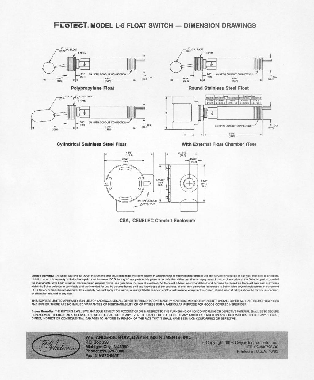
427
428 HONEYWELL UDC1200 MICRO-PRO HONEYWELL Universal UDC1200 Digital MICRO-PRO Controller Start-Up Guide 1. Mounting Page 2 2. Wiring Page 2 3. Select Mode Page 3 4. Configuration Mode Page 3 5. Setup Mode Page 6 6. Operator Mode Page 7 7. Automatic Tuning Mode Page 8 8. Product Information Mode Page 8 9. Installing Option Modules Page Error Fault Indications Page 10 The full users manual can be downloaded from Honeywell IMC Web page UDC 1200 Start-Up Guide Rev 1
 thick.")
429 HONEYWELL UDC1200 MICRO-PRO Universal Digital Controller CAUTION: Installation and configuration should be performed only by personnel who are technically competent to do so. Local Regulations regarding electrical installation & safety must be observed. 1. INSTALLATION Panel-Mounting The mounting panel must be rigid and may be up to 6.0mm (0.25 inches) thick. The cut-out required for the instrument is shown on the right. Instruments may be mounted side-by-side in a multiple installation for which the cut-out width (for n instruments) is (48n-4)mm or (1.89n-0.16)inches. Panel Instrument Ratchets Gasket Slide mounting clamp over the instrument housing towards rear face of mounting panel until the tongues engage in ratchets and instrument is clamped in position. Hold instrument firmly in position (apply pressure to bezel only) 45 x 45mm CAUTION: Do not remove the panel gasket; it is a seal against dust and moisture. 2. WIRING Rear Terminal Wiring USE COPPER CONDUCTORS (EXCEPT FOR T/C INPUT) Single Strand wire gauge: Max 1.2mm (18SWG) CAUTION: Check information label on housing for correct operating voltage before connecting supply to Power Input Fuse: V ac 1amp anti-surge 24/48V ac/dc 315mA anti-surge UDC 1200 Start-Up Guide Rev 1
430 3. SELECT MODE Select mode is used to access the configuration and operation menu functions. It can be accessed at any time by holding down and pressing. Once in select mode, press or to select the required mode. An unlock code is required to prevent unauthorised entry to Configuration, Setup & Automatic Tuning modes. Press or to enter the correct code number, then press to proceed. Mode Upper Display Lower Display Description Default Unlock Codes Operator Optr SLCt Normal instrument operation. None Set Up SetP SLCT Tailor settings to the application. Configuration Conf SLCT Configures the instrument for use. Product Info Info SLCT Check manufacturing information. None Auto-Tuning Atun SLCT Invoke Pre-Tune or Self-Tune. Note: The instrument will always return automatically to Operator mode if there is no key activity for 2 minutes. First select Configuration mode from Select mode (refer to section 2). 4. CONFIGURATION MODE First select Configuration mode from Select mode (refer to section 3). Press to scroll through the parameters, then press or to set the required value. To accept a change must be pressed, otherwise parameter will revert to previous value. To exit from Configuration mode, hold down and press, to return to Select mode. Note: Parameters displayed depends on how instrument has been configured. Parameters marked * are repeated in Setup Mode. Parameter Lower Display Upper Display Adjustment range Default Input Range/Type See following table for possible codes J T/C Code Input Type & Range Code Input Type & Range Code Input Type & Range bc B: ºC L.C L: ºC bf B: ºF L.F L: ºF P24F PtRh20% vs 40%: ºF CC C: ºC NC N: ºC PTC Pt100: ºC CF C: ºF NF N: ºF PtF Pt100: ºF JC J: ºC rc R: ºC Pt.C Pt100: ºC JF J: ºF rf R: ºF Pt.F Pt100: ºF j.c J: ºC SC S: ºC 0 20 ma DC j.f J: ºF SF S: ºF 4 20 ma DC KC K: ºC tc T: ºC 0 50 mv DC KF K: ºF tf T: ºF mv DC k.c K: ºC t.c T: ºC 0 5 V DC K.F K: ºF t.f T: ºF 1 5 V DC LC L: ºC PtRh20% vs 40%: 0 10 V DC P24C LF L: ºF ºC 2 10 V DC Parameter Scale Range Upper Limit Scale Range Lower Limit Decimal point position Control Type Lower Display Upper Display Adjustment range Default Scale Range Lower Limit +100 to Range Max Range max (Lin=1000) Range Min. to Scale Range Upper Limit -100 Range min (Linear=0) 0=XXXX, 1=XXX.X, 2=XX.XX, 3=X.XXX 1 (non-temperature ranges only) Primary (heat) only Primary & Secondary (heat/cool) UDC 1200 Start-Up Guide Rev 1
431 Parameter Lower Upper Adjustment range Default Display Display Primary Output Reverse Acting Control Action Direct Acting Alarm 1Type Process High Alarm Process Low Alarm Deviation Alarm Band Alarm No alarm High Alm 1 value* Range Min. to Range Max Range Max. Low Alm 1 value* in display units Range Min. Band Alm 1 value* 1 LSD to span from setpoint in display units Dev. Alm 1 value* +/- Span from setpoint in display units Alm 1 Hysteresis* 1 LSD to full span in display units Alarm 2 Type* High Alm 2 value* Range Max. Low Alm 2 value* Range Min. Options as for alarm 1 Band Alm 2 value* Dev. Alm 2 Value* Alm 2 Hysteresis* Loop Alarm (disabled) or (enabled) Loop Alarm Time* 1 sec to 99 mins. 59secs (only applies if primary proportional band = 0). Alarm Inhibit No alarms Inhibited Alarm 1 inhibited Alarm 2 inhibited Alarm 1 and alarm 2 inhibited Output 1 Usage Primary (Heat) Power Secondary (Cool) Power Alarm 1, Direct Alarm 1, Reverse Alarm 2, Direct Alarm 2, Reverse Loop Alarm, Direct Loop Alarm, Reverse Logical Alarm 1 OR 2, Direct Logical Alarm 1 OR 2, Reverse Logical Alarm 1 AND 2, Direct Logical Alarm 1 AND 2, Reverse Retransmit SP Output Linear Output 1 Range Retransmit PV Output 0 5 V DC output V DC output 2 10 V DC output 0 20 ma DC output 4 20 ma DC output UDC 1200 Start-Up Guide Rev 1
432 Parameter Lower Upper Adjustment range Default Display Display Retransmit Output to 9999 (display value at which output will Range Scale maximum be maximum) max Retransmit Output to 9999 (display value at which output will Range Scale minimum be minimum) min Output 2 Usage Sec or As for output 1 Al2 Lin. O/P 2 Range Retransmit Output 2 Scale maximum to 9999 (display value at which output will be maximum) Range max Retransmit Output 2 Scale minimum to 9999 (display value at which output will be minimum) Range min Output 3 Usage As for output 1 Linear Output 3 Range Retransmit Output to 9999 (display value at which output will Range Scale maximum be maximum) max Retransmit Output to 9999 (display value at which output will Range Scale minimum be minimum) min Display Strategy,,,, or (refer to section 7) Comms Protocol ASCII Mm Mm Modbus with no parity Mm Modbus with Even Parity Mm Modbus with Odd Parity Bit rate. 1.2 kbps kbps. 4.8 kbps. 9.6 kbps kbps Comms Address (Modbus), 1-99 (ASCII) Comms Write Read only or read/write r_ Ww Digital Input Usage Setpoint 1 / Setpoint 2 select Automatic / Manual select Config Lock Code 0 to 9999 * Refer to the full user guide for further details on these parameters. UDC 1200 Start-Up Guide Rev 1
433 5. SETUP MODE Note: Configuration must be completed before adjusting Setup parameters. First select Setup mode from Select mode (refer to section 3). While in Setup Mode is lit. Press to scroll through the parameters, then press or to set the required value. To exit from Setup mode, hold down and press, to return to Select mode. Note: Parameters displayed depends on how instrument has been configured. Parameter Lower Upper Display Default Display Adjustment Range Input Filter Time constant OFF or 0.5 to secs. Process Variable Offset +/- Span of controller Primary (Heat) power PPWw Current power levels (read only) N/A Secondary (Cool) power SPWw Primary Proportional Band 0.0% (ON/OFF) and 0.5% to 999.9% of input span.. Secondary Proportional Band Automatic Reset (Integral Time) 1 sec to 99 mins 59 secs and OFF. Rate (Derivative Time) 00 secs to 99 mins 59 secs. Overlap/Deadband -20 to +20% of Primary and Secondary Proportional Band Manual Reset (Bias) 0%(-100% if dual control) to 100% Primary ON/OFF Differential 0.1% to 10.0% of input span Secondary ON/OFF Diff. centered about the setpoint. Prim. & Sec. ON/OFF Diff. Setpoint Upper Limit Current Setpoint to Range max R/max Setpoint Lower limit Range min to Current Setpoint R/min Primary Output Power Limit 0% to 100% of full power. Output 1 Cycle Time Output 2 Cycle Time 0.5, 1, 2, 4, 8, 16, 32, 64, 128, 256 or 512 secs. Output 3 Cycle Time High Alarm 1 value R/max Range Min. to Range Max. Low Alarm 1 value R/min Deviation Alarm 1 Value +/- Span from SP in display units Band Alarm 1 value 1 LSD to span from setpoint Alarm 1 Hysteresis 1 LSD to full span in display units High Alarm 2 value R/max Range Min. to Range Max. Low Alarm 2 value R/min Deviation Alarm 2 Value +/- Span from SP in display units Band Alarm 2 value 1 LSD to span from setpoint Alarm 2 Hysteresis 1 LSD to full span in display units Loop Alarm Time 1 sec to 99 mins. 59secs.. Auto Pre-tune disabled or Auto/manual Control selection enabled Setpoint ramping SP Ramp Rate Value rp 1 to 9999 units/hour or Off (blank) Off SP Value SP Scale range upper to lower limits SP1 Value SP2 Value _ SP1 _ SP2 Scale range upper to lower limits _ indicates currently active SP. Scale Range min Setup Lock Code 0 to 9999 UDC 1200 Start-Up Guide Rev 1
434 6. OPERATOR MODE This mode is entered at power on. It can also be accessed from Select mode (see section 3). Note: All configuration mode and Setup mode parameters must be set as required before starting normal operations. Press to scroll through the parameters, then press or to set the required value. Note: All parameters in Display strategy 6 are read only, and can only be adjusted via Setup mode. Upper Display Lower Display Strategy When Description Display Visible PV Value Active SP Value 1 & 2 (initial screen) PV and target value of selected SP SP adjustable in Strategy 2 PV Value Actual SP Value 3 & 6 (initial screen) PV and actual value of selected SP (e.g. ramping SP value). Read only PV Value (Blank) 4 (initial screen) Process variable only. Read only Active SP Value (Blank) 5 (initial screen) Target value of selected setpoint only. Read only SP Value SP1 Value SP2 Value Actual SP Value Ramp Rate Active Alarms SP _ SP1 _ SP2 SPrP rp AL t 1, 3, 4, 5 & 6 if digital input is not _ lit if dig I/P = and active SP is SP1 _ lit if dig I/P = and active SP is SP2 enabled and rp is not zero enabled in Setup mode When one or more alarms are active. ALM indicator will also flash L L21 L Target value of SP Adjustable except in Strategy 6 Target value of SP1 Adjustable except in Strategy 6 Target value of SP2 Adjustable except in Strategy 6 Actual (ramping) value of selected SP Read only SP ramping rate, in units per hour. Adjustable except in Strategy 6 Alarm 2 active Alarm 1 active Loop Alarm active Manual Control If is set to in Setup mode, manual control can be selected/de-selected by pressing the key while in Operator mode, or by changing the status of the digital input if has been configured for in Configuration mode. The indicator will flash while in Manual Control mode and the lower display will show xxx (where xxx is the current manual power level). Switching to/from manual mode is via Bumpless Transfer. Press or to set the required output power. Caution: Not restricted by limit. UDC 1200 Start-Up Guide Rev 1
435 7. AUTOMATIC TUNING MODE First select Automatic tuning mode from Select mode (refer to section 3). Press to scroll through the modes, then press or to set the required value. To exit from Automatic tuning mode, hold down and press to return to Select mode. Pre-tune is a single-shot routine and is thus self-disengaging when complete. If in Setup mode =, Pre-tune will attempt to run at every power up*. Refer to the full user guide (available from your supplier) for details on controller tuning. Parameter Pre-Tune Self-Tune Lower Display Upper Display Adjustment Range On or Off. Indication remains OFF if automatic tuning cannot be used at this time*. Default Off Tune Lock 0 to 9999 * Note: Automatic tuning will not engage if either proportional band = 0. Also, Pre-tune will not engage if setpoint is ramping, or the PV is within 5% of span of the setpoint. 8. PRODUCT INFORMATION MODE First select Product information mode from Select mode (refer to section 3). Press to view each parameter. To exit from Product Information mode, hold down and press to return to Select mode. Note: These parameters are all read only. Parameter Lower Upper Description Display Display Input type Universal input only Option 1 module type fitted No option fitted. Relay SSR drive Triac Linear voltage / Current output Option 2 type fitted Option 3 type fitted As Option 1. Auxiliary Option module type No option fitted fitted RS485 comms Digital Input Firmware type Value displayed is firmware type number Firmware issue Value displayed is firmware issue number Product Revision Level Value displayed is Product Revision level. Date of manufacture Mm Manufacturing date code (mmyy) Serial number 1 First four digits of serial number Serial number 2 Middle four digits of serial number Serial number 3 Last four digits of serial number UDC 1200 Start-Up Guide Rev 1
.")
.")
436 9. Installing Option Modules Installing Option Modules CAUTION: Turn off all power. Remove instrument by gripping the sides of the front panel and pulling the instrument out of its housing. Note its orientation. To access modules 1 or A, first detach the PSU and CPU boards from the front moulding by lifting first the upper, and then lower mounting struts. Gently separate the boards. a). Plug the required option modules into the correct connectors, as shown below. b). Locate the tongues on each module into the corresponding slot in the board opposite. c). Hold the main boards together while relocating them back on the mounting struts. d). Replace the instrument by aligning the CPU and PSU boards with their guides in the housing, then slowly push the instrument back into position. Note: The instrument will automatically detect which option modules have been fitted. Mounting Struts CPU PCB Option Module 1 Option Module A Option Module 2 Option Module 3 PSU PCB Option Module 1 Connectors PL7 & PL8 Option Module 2 Connector PL4A Option Module A Connectors PL5 & PL6 Option Module 3 Connector PL4B UDC 1200 Start-Up Guide Rev 1
Eclipse Single-Ended Radiant Tube Burners
 325 Design Guide 3/8/2011 Eclipse Single-Ended Radiant Tube Burners Models SER450, SER600, & SER800 Version 5 Metallic Ceramic Copyright Copyright 2007 by Eclipse, Inc. All rights reserved worldwide. This
Eclipse RatioAir Burners
 Data 115-1 10/1/07 Eclipse RatioAir Burners Main Specifications - RA0 PARAMETER Maximum input, () at neutral chamber conditions 60Hz Packaged Maximum input, () at neutral chamber conditions 50Hz Packaged
RatioAir Burners. Model RA1000. Data /31/05. Main Specifications - RA1000
 Main Specifications - RA1000 PARAMETER Maximum input, Btu/hr (kw) at neutral chamber conditions. (Natural Gas) 60Hz Packaged Blower 50Hz Packaged Blower Minimum input, Btu/hr (kw) Lower inputs may be achieved.
RatioAir Burners. Model RA0750. Data /31/05. Main Specifications - RA0750
 Main Specifications - RA0750 PARAMETER Maximum input, Btu/hr (kw) at neutral chamber conditions. (Natural Gas) 60Hz Packaged 50Hz Packaged Minimum input, Btu/hr (kw) Lower inputs may be achieved. Contact
The installation and maintenance of this product must be done under the supervision of an experienced
 AA...A2 Differential Air Pressure Switch Installation Instructions USA CDN Table of Contents Table of Contents...Page 1 Approvals...Page 1 Attention...Page 1 Specification...Page 2 Model Description &
O.K. Safety first CDN USA. Table of Contents. Approvals. Attention IFGC CSA UL ANSI NFPA
 AA...A2 Differential Air Pressure Switch Installation Instructions USA CDN Table of Contents Table of Contents...Page 1 Approvals...Page 1 Attention...Page 1 Specification...Page 2 Model Description &
Eclipse AutoTite Automatic Gas Shut-Off Valves
 Installation Guide 756 4/26/2013 Eclipse AutoTite Automatic Gas Shut-Off Valves 2000AT Series Version 2 Copyright Copyright 2011 by Eclipse, Inc. All rights reserved worldwide. This publication is protected
Eclipse RatioAir Burners
 Parameter Maximum Input, BTU/hr (kw) 1, Minimum Input, BTU/hr (kw) Lower inputs may be achieved. Contact factory. Main Gas Inlet Pressure, "w.c. (mbar) 3 Fuel pressure at ratio regulator inlet. High Fire
Eclipse AutoTite Automatic Gas Shut-Off Valves
 756 Instruction Manual //0 Eclipse AutoTite Automatic Gas Shut-Off Valves 000AT Series Version Copyright Copyright 0 by Eclipse, Inc. All rights reserved worldwide. This publication is protected by federal
Info 110 4/98. RatioMatic Burners. RM Series version through 600 Sizes. 750 through 2000 Sizes
 Info 110 4/98 RatioMatic Burners RM Series version 1.01 50 through 600 Sizes 750 through 2000 Sizes For Ratiomatic Serial Numbers 95-5500 and Above Version 1.01 7/97 Contents 1.0 Operating Parameters &
Data /1/07 Eclipse RatioAir Burners Model RA0040
 Maximum input, () at neutral chamber conditions 60Hz Packaged Maximum input, () at neutral chamber conditions 50Hz Packaged Minimum input, () Lower inputs may be achieved. Contact factory. Main Gas Inlet
Commonwealth of Massachusetts Approved Product Approval code G
 AA...A4 Differential Air Pressure Switch Installation Instructions USA CDN Table of Contents Table of Contents...Page 1 Approvals...Page 1 Attention...Page 1 Specification...Page 2 Model Description &
ECLIPSE AIR HEAT BURNERS Series AH, DAH, TAH & CAH
 Info 140 11/4/03 ECLIPSE AIR HEAT BURNERS Series AH, DAH, TAH & CAH U.S. Reissue Pat. No. 26,244 Canadian Pat. No. 743,782 AH, Front View Data 140-1 AH, Back View Data 140-1 TAH Data 140-3 DAH, Blower
INDUSTRIAL MICRODIFFUSION DUAL-FUEL BURNERS
 Operations and Maintenance Manual for INDUSTRIAL MICRODIFFUSION DUAL-FUEL BURNERS Models MD-25-OG MD-7500-OG December 2012 Copyright 2012 Periflame, Design Guide 113 Industrial Dual-Fuel Burners, 12/01/2012
Eclipse BoostPak Packaged Gas Booster System
 630-6 Installation Guide 7/8/2010 Eclipse BoostPak Packaged Gas Booster System Model MD, ML and MX Version 2 Copyright Copyright 2010 by Eclipse, Inc. All rights reserved worldwide. This publication is
 Data 330-3 9/15/07 Eclipse ImmersoJet Burners Model 3 IJ Version 2 Main Specifications PARAMETER BLOWER SIZE Blower Type 6" w.c. Packaged (60Hz) 10" w.c. Packaged (60Hz) Remote Blower Maximum Input (Btu/hr)
G72x Series Direct Spark Ignition Controls
 Installation Sheets Manual 121 Gas Combustion Combination Controls and Systems Section G Technical Bulletin G72x Issue Date 1299 G72x Series Direct Spark Ignition Controls Figure 1: G72x Direct Spark Ignition
2.0 Burner Operating Parameters and Requirements
 ECLIPSE INFORMATION GUIDE Silicon Carbide Radiant Auto-Recupes Info 322 2/99 WARNING Handle silicon carbide tubes carefully. Do not drop them or hammer on them. Although they feature excellent mechanical
G76x Direct Spark Ignition Controls
 Installation Sheets Manual 121 Gas Combustion Combination Controls and Systems Section G Technical Bulletin G76x Issue Date 0400 G76x Direct Spark Ignition Controls Figure 1: G76x Direct Spark Ignition
North American Automatic Manual Reset and Motorized Valves
 Combustion North American Automatic Manual Reset and Motorized Valves 1516 Manual Reset 1517 Motorized 1516/1517 Automatic Oil Shutoff Valves Agency approvals: UL, FM, CSA Proof-of-Closure Switch High
Eclipse Trilogy Actuator
 Instruction Manual 902 12/7/2009 Eclipse Trilogy Actuator Series T500 Version 1 Copyright Copyright 2009 by Eclipse, Inc. All rights reserved worldwide. This publication is protected by federal regulation
X4 Installation and Operation Manual - POWER FLAME INCORPORATED
 7.13.2 Set the burner s combustion air inlet damper to the approximate setting as shown in this manual for the desired firing rate. Also, verify that the correct main orifice is installed in the main orifice
B21 Series BASOTROL Gas Valve
 Installation Instructions B21 Issue Date September 19, 2017 Installation IMPORTANT: These instructions are intended as a guide for qualified personnel installing or servicing BASO Gas Products. Carefully
dv Sentry TM 208V 600V INSTALLATION GUIDE Quick Reference ❶ How to Install Pages 6 14 ❷ Startup/Troubleshooting Pages WARNING
 dv Sentry TM 208V 600V INSTALLATION GUIDE FORM: DVS-IG-E REL. January 2018 REV. 003 2018 MTE Corporation High Voltage! Only a qualified electrician can carry out the electrical installation of this filter.
Declaration of Conformity
 Declaration of Conformity We, Manufacturer: Spartanics Ltd. 3605 Edison Place Rolling Meadows, Illinois 60008 Phone: 847-394-5700 Fax: 847-394-0409 USA ENGLISH declare under our sole responsibility that
Eclipse Vortometric Burners Series HI
 Version Burner Model Parameter 6V 8V V V V 6V 8V V V 8V 3V 36V Max. Input MM BTU/hr (MW) (.8).5 (3.) 7 (5.0) 3 (6.7) 3 (9.) () (6.) 78 (3) 90 (6) 5 (37) (7) (6) Min. Input MM BTU/hr (MW) (Natural Gas)
Model LA 4100 Time Delay OFF Controller
 ISIMET LA Series Model LA 4100 Time Delay OFF Controller Installation, Operation and Maintenance Manual Application: The Time Delay OFF Controller operates as a single output controller where the application
M T E C o r p o r a t i o n. dv/dt Filter. Series A VAC USER MANUAL PART NO. INSTR REL MTE Corporation
 M T E C o r p o r a t i o n dv/dt Filter Series A 440-600 VAC USER MANUAL PART NO. INSTR - 019 REL. 041119 2004 MTE Corporation IMPORTANT USER INFORMATION NOTICE The MTE Corporation dv/dt Filter is designed
Field proven low emissions. State-of-the-art low NOx firing - adjustable for application flexibility
 -.9- KINEDIZER LE High capacity low NOx gas burners Field proven low emissions. State-of-the-art low NOx firing - adjustable for application flexibility Lower NOx and less excess air than standard KINEDIZER
Design and Application Details
 Model 400 OVENPAK Gas Page 2105 Design and Application Details OVENPAK s are nozzle-mixing gas burners for many industrial direct-fired applications where clean combustion and high turndown are required.
BGD278 Series BASOTROL CE Approved Gas Valve
 Product Bulletin Issue Date November 16, 2012 BGD278 Series BASOTROL CE Approved Gas Valve The BGD278 Series gas valve is a combination main and pilot valve intended for use in conjunction with solid-state
LANDFILL GAS ELEVATED (CANDLESTICK) FLARE SYSTEM
 FLARE SYSTEM") LANDFILL GAS ELEVATED (CANDLESTICK) FLARE SYSTEM Part 1. General 1.01 Description A. This section describes a candlestick flare system for the combustion of landfill gases. The flare system must be of
LANDFILL GAS ELEVATED (CANDLESTICK) FLARE SYSTEM Part 1. General 1.01 Description A. This section describes a candlestick flare system for the combustion of landfill gases. The flare system must be of
Q35 Series Automatic Vent Damper System
 Installation Sheets Manual 121 Energy Conservation and Miscellaneous Kits Section Q Technical Bulletin Q35 Issue Date 0999 Q35 Series Automatic Vent Damper System Figure 1: Q35 Automatic Vent Damper System
G600 Series Replacement Intermittent Pilot Ignition Controls
 Installation Instructions G600 Issue Date 0601 G600 Series ment Intermittent Pilot Ignition Controls Installation IMPORTANT: These instructions are intended as a guide for qualified personnel installing
E Series CE Approved Intermittent Pilot Ignition Control
 Installation Instructions Issue Date January 11, 2013 E Series CE Approved Intermittent Pilot Ignition Control Application The E Series CE Approved Intermittent Pilot Ignition Control is a safety control
Design and Application Details
 Model 400 OVENPAK -II Gas Page 2153 Design and Application Details OVENPAK -II s are nozzle-mixing gas burners for many industrial direct-fired applications where clean combustion and high turndown are
FAIRCHILD T5200 SERIES ELECTRO-PNEUMATIC TRANSDUCER Installation, Operation and Maintenance Instructions
 FAIRCHILD T500 SERIES ELECTRO-PNEUMATIC TRADUCER Installation, Operation and Maintenance Instructions Identification Number Underwriting Group Factory Mutual Canadian Standard T (F) (C) 500- Approval Class
XID ENHANCEMENT SYSTEM IMPROVED EFFICIENCY AND PERFORMANCE
 IMMERSION FIRED HOT WATER BOILER April 1, 2003 GENERAL DESCRIPTION The Sellers immersion fired hot water boiler is a horizontal, single pass, firetube boiler designed to burn natural gas. The unique burner
VWR Zero Air Generator
 Technical Information Installation, Operation, and Maintenance Manual VWR 89237-564 Zero Air Generator Figure 1 - VWR Zero Air Generator These instructions must be thoroughly read and understood before
Matrix APAX. 380V-415V 50Hz TECHNICAL REFERENCE MANUAL
 Matrix APAX 380V-415V 50Hz TECHNICAL REFERENCE MANUAL WARNING High Voltage! Only a qualified electrician can carry out the electrical installation of this filter. Quick Reference ❶ Performance Data Pages
model ps600 Address all communications and shipments to: FEDERAL SIGNAL CORPORATION
 MODEL: PS600 HZ: 60 A model ps600 installation and service manual for federal model ps600 FEDERAL SIGNAL CORPORATION POWER SUPPLY VOLTS: SERIES: 120VAC FEDERAL SIGNAL CORPORATION UNIVERSITY PARK, IL. U.S.A.
Owner's/Installation Manual
 Owner's/Installation Manual Power Management Module (PMM) and Starter Kit NOTE: The starter kit must be purchased and installed prior to individual PMM usage. Model Numbers: 00686-0 PMM 00699-0 PMM WITH
PreSoak System (NonFoaming) DU PS1-HP DU PS6-HP
 DU PS1-HP DU PS6-HP") PreSoak System (NonFoaming) DU PS1-HP DU PS6-HP Serial Number: Owner s Manual #0786 040810 Installation Date: Please read and u n d e r s t a n d t h i s manual. Store in safe location for future reference.
PreSoak System (NonFoaming) DU PS1-HP DU PS6-HP Serial Number: Owner s Manual #0786 040810 Installation Date: Please read and u n d e r s t a n d t h i s manual. Store in safe location for future reference.
Installation Operation Maintenance ADDENDUM
 Installation Operation Maintenance ADDENDUM Bulletin #: PS-IOM-HYPO2-0111-A FACTORY SERVICE POLICY If you are experiencing a problem with your Pulsafeeder pump, first review the IOM, and consult the troubleshooting
Packaged Gas Burner. Low CO and NOx emissions. Direct spark ignition. Factory pre-set for ease of start-up and operation
 PBGII Packaged Gas Burner PBGII-1 Edition 08-11 Many standard and configurable options available to suit a wide variety of applications Choose from three standard fuel manifolds for natural gas and vaporous
Specifications of MAXON VALUPAK burners for 50 Hz operation
 1-1.5-7 Specifications of MAXON VALUPAK burners for 50 Hz operation Capacity data in kw Gross heating value = 10.9 kwh/m 3 (st), d = 0.6. All figures are for balanced - 0 mbar - duct pressure VALUPAK size
Q= C. v P S Refer to Table 1 for part numbers and shipping weights. Accessories: Table 1: Valve Part Numbers and Specifications
 1 of 9 1. DESCRIPTION The Viking Flow Control Valve is a quick opening, differential diaphragm flood valve with a spring loaded floating clapper. The Flow Control Valve can be used to facilitate manual
Screwed Brass Orfices (SBO) 1/2-2 1/2 NPT; rated 250 PSI. Carbon Steel Orfices (CO) 2 1/2-24 ; rated 250 PSI ATTENTION
 1/2-2 1/2 NPT; rated 250 PSI. Carbon Steel Orfices (CO) 2 1/2-24 ; rated 250 PSI ATTENTION") SBO and CO Gas Orifices Installation and Selection Manual Screwed Brass Orfices (SBO) 1/2-2 1/ ; rated 250 PSI Low cost metering device permits accurate setting of burner air and gas flow for optimum efficiency.
SBO and CO Gas Orifices Installation and Selection Manual Screwed Brass Orfices (SBO) 1/2-2 1/ ; rated 250 PSI Low cost metering device permits accurate setting of burner air and gas flow for optimum efficiency.
REFERENCE MANUAL FORM: MX-TRM-E REL REV MTE
 Matrix APAX 380V-415V 50Hz TECHNICAL REFERENCE MANUAL FORM: MX-TRM-E REL. September 2014 REV. 002 2014 MTE Corporation WARNING High Voltage! Only a qualified electrician can carry out the electrical installation
DIESEL EXHAUST FLUID PUMPING ACCESSORIES INSTALLATION GUIDE
 DIESEL EXHAUST FLUID PUMPING ACCESSORIES INSTALLATION GUIDE The information in this publication is provided for reference only. While every effort has been made to ensure the reliability and accuracy of
Introduction. System Components
 The Selectra SERIES 94 is for use with either direct or indirect gas fired units (furnaces, ovens, etc.). The system may be field installed on existing equipment or specified for new equipment installation.
Model LA 4300 Time Delay OFF Controller
 ISIMET LA Series Model LA 4300 Time Delay OFF Controller Installation, Operation and Maintenance Manual Application: The Time Delay OFF Controller operates as a single output controller where the application
MS Application. Features. Proportional Valve Actuator General Instructions
 Proportional Valve Actuator Application The Proportional Valve Actuator is a non-spring return actuator used with proportional to 10 Vdc or 4 to 0 ma controllers and standard 1/" to 1-1/4" two-way and
100% OUTSIDE AIR MAKE-UP UNITS WITH DISCHARGE TEMPERATURE CONTROL & c.pco DIRECT DIGITAL CONTROL MODULE
 100% OUTSIDE AIR MAKE-UP UNITS WITH DISCHARGE TEMPERATURE CONTROL & c.pco DIRECT DIGITAL CONTROL MODULE Start-up must be performed by a trained, experienced service person. The following general start-up
V5197A Firing Rate Gas Valve
 V5197A Firing Rate Gas Valve FEATURES PRODUCT DATA APPLICATION The V5197A is a firing rate valve used to provide variable flow control of air, natural gas, liquefied petroleum (LP), and manufactured gases.
Design and Application Details
 Model 400 OVENPAK Gas Page 2153 Design and Application Details OVENPAK s are nozzle-mixing gas burners for many industrial direct-fired applications where clean combustion and high turndown are required.
G821L/G822L Series Integrated Function Direct Spark Ignition Controls
 Installation Sheets Manual 121 Gas Combustion Combination Controls and Systems Section G Technical Bulletin G821L/G822L Issue Date 1199 G821L/G822L Series Integrated Function Direct Spark Ignition Controls
Start-up Instructions
 RadMax Burners Page 400-S- Start-up Instructions Read complete instructions before proceeding and familiarize yourself with all the system s equipment and components. Verify that all equipment has been
F-4600 INLINE ULTRASONIC FLOW METER Installation and Operation Guide
 F-4600 INLINE ULTRASONIC FLOW METER Installation and Operation Guide 11451 Belcher Road South, Largo, FL 33773 USA Tel +1 (727) 447-6140 Fax +1 (727) 442-5699 1054-7 / 34405 www.onicon.com sales@onicon.com
Model F822 thru F834 Mulsifyre Directional Spray Nozzles, Open, High Velocity General Description
 Technical Services: Tel: () 31-931 / Fax: () 791-55 Model F thru F3 Mulsifyre Directional Spray Nozzles, Open, High Velocity General Description The Mulsifyre Nozzles are open (nonautomatic) nozzles and
MODEL A96 SERIES. 130Vdc Switchmode Utility Rectifier / Battery Charger. Used with LaMarche Power Cage ECN/DATE
 MODEL A96 SERIES 130Vdc Switchmode Utility Rectifier / Battery Charger Used with LaMarche Power Cage CPN112138 ECN/DATE ISSUE DATE: ECN 17010-12/05 106 BRADROCK DRIVE DES PLAINES, IL. 60018-1967 (847)
Model LA 4400 Time Delay OFF Controller
 ISIMET LA Series Model LA 4400 Time Delay OFF Controller Installation, Operation and Maintenance Manual Application: The Time Delay OFF Controller with integral 24-hr. programmable time clock operates
Power Flame Incorporated
 Power Flame Incorporated SUGGESTED SPECIFICATION FOR MODEL HP COMBINATION GAS/OIL BURNERS THE POWER TO MANAGE ENERGY 2001 South 21st Street, Parsons, Kansas 67357 Telephone 316-421-0480, Fax 316-421-0948
SureFire II TM Pilot Forced Draught. Gas pilot type SP-32-xx-FD. Instruction Manual 1. INTRODUCTION 2. OPERATION PRINCIPLE AND TECHNICAL SPECIFICATION
 SF-200 OCTOBER 10, 2016 SureFire II TM Pilot Forced Draught Gas Pilot type SP-32-xx-FD Instruction Manual 1. INTRODUCTION This Instruction Manual contains a description of the type SP-32-xx-FD gas pilot
Locktite Manual Reset Gas Shut-Off Valves
 Instruction Manual 750, 10/25/04 Locktite Manual Reset Gas Shut-Off Valves Series 200 LT Eclipse 200 LT valves are manually opening valves that automatically shut off the gas supply to a combustion system
Patient Care Facility
 ISIMET Patient Care Facility DLA Controller Individual Room Configuration Style 1 W/ Ver 4.41 pcb & Pulse Relay pcb Installation, Operations, Start-up and Maintenance Instructions Meets all Standards for
G96 Series BASOTROL Dual Operator Valve
 Product Bulletin Issue Date March 5, 2013 G96 Series BASOTROL Dual Operator Valve The G96 Series BASOTROL valves are combination, dual operator, automatic valves available with or without a pressure regulator.
Drug Testing Labs. Style 2 W/ Ver 4.41 pcb & Pulse Relay pcb(s) Installation, Operations, Start-up and Maintenance Instructions
 Installation, Operations, Start-up and Maintenance Instructions") ISIMET Drug Testing Labs DLA Controller Style 2 W/ Ver 4.41 pcb & Pulse Relay pcb(s) Installation, Operations, Start-up and Maintenance Instructions Meets all Standards for Canadian Industrial Control
ISIMET Drug Testing Labs DLA Controller Style 2 W/ Ver 4.41 pcb & Pulse Relay pcb(s) Installation, Operations, Start-up and Maintenance Instructions Meets all Standards for Canadian Industrial Control
Patient Care Facility
 ISIMET Patient Care Facility DLA Controller Individual Room Configuration Style 1 W/ Ver 4.41 pcb & Pulse Relay pcb Installation, Operations, Start-up and Maintenance Instructions Meets all Standards for
Drug Testing Labs. Style 2 W/ Ver 4.41 pcb & Pulse Relay pcb(s) Installation, Operations, Start-up and Maintenance Instructions
 Installation, Operations, Start-up and Maintenance Instructions") ISIMET Drug Testing Labs DLA Controller Style 2 W/ Ver 4.41 pcb & Pulse Relay pcb(s) Installation, Operations, Start-up and Maintenance Instructions Meets all Standards for Canadian Industrial Control
ISIMET Drug Testing Labs DLA Controller Style 2 W/ Ver 4.41 pcb & Pulse Relay pcb(s) Installation, Operations, Start-up and Maintenance Instructions Meets all Standards for Canadian Industrial Control
U00X ULTRASONIC LEVEL SWITCH. Ultrasonic Liquid Level Switches INSTALLATION AND OPERATIONS MANUAL. For Models: U002, U003 & U004
 U00X ULTRASONIC LEVEL SWITCH INSTALLATION AND OPERATIONS MANUAL Ultrasonic Liquid Level Switches For Non-Hazardous Locations For Models: U002, U003 & U004 READ THIS MANUAL PRIOR TO INSTALLATION This manual
North American 4485 Tempest SE
 Combustion North American 4485 Tempest SE Medium/High Velocity Gas Burner Low NOx gas burner, durable construction and flexible desgin to fit a variety of applications. NPT or BSP air/gas inlets, adjustable
G861 Series Integrated Function. Direct Spark Ignition Control
 Installation Sheets Manual 121 Gas Combustion Combination Controls and Systems Section G Technical Bulletin G861 Issue Date 0699 G861 Series Integrated Function Direct Spark Ignition Control Figure 1:
Technical Manual. DLM Module. This manual should remain with the unit.
 Technical Manual DLM Module This manual should remain with the unit. Safety Rules SAVE THESE INSTRUCTIONS! Read the following information carefully before attempting to install, operate or service this
Contents. Overview. Safety Instructions. Before Installation. Installation. Operation. Maintenance. Replacement Parts. System Specifications 8 01
 PrintPRO Universal Contents Overview 1 01 02 03 Overview of your extraction system (front) Overview of your extraction system (back) Overview of the Control Panel Safety Instructions 2 01 Important safety
ProFlo FatBoy
 The Standard For Professional Grade Diaphragm Pumps. ProFlo 3300 5500 FatBoy Operational and Installation Guidelines, Repair & Parts Contents 3300 5500 Fatboy Operational and Installation Guidelines...2
VQ400M SERIES CLASS A COMBINATION VALVES PRODUCT HANDBOOK APPLICATION
 VQ400M SERIES PRODUCT HANDBOOK APPLICATION The VQ400M Series class A safety combination valves are used for control and regulation of gaseous fluids in gas power burners, atmospheric gas boilers, melting
North American 4575 HiRAM
 Combustion North American 4575 HiRAM The quality and performance of our Tempest, but bigger. Low NOx burner High Velocity - High Turndown Inputs to 4-25 million Btu/hr Direct Spark or Pilot Lighting Furnace
MODEL 900 IMPELLER-TYPE FLOW METER
 MODEL 900 IMPELLER-TYPE FLOW METER - For Water Applications - INSTALLATION & INSTRUCTION MANUAL 8635 Washington Avenue Racine, Wisconsin 53406 Toll Free: 800.235.1638 Phone: 262.639.6770 Fax: 262.417.1155
Series 20 Installation Instructions
 Series 20 Installation Instructions Installation Instructions and field service checklist Read these instructions carefully. Failure to follow them could result in a fire or explosion causing property
Electropneumatic Converters i/p Converters Type 6111 Mounting and Operating Instructions EB 6111 EN
 Electropneumatic Converters i/p Converters Type 6111 Fig. 1 Type 6111 in standard version Fig. Type 6111 mounted on a supply air manifold Fig. 3 Type 6111 in field enclosure Mounting and Operating Instructions
DIESEL EXHAUST FLUID PUMP MOTOR ASSEMBLY REPLACEMENT GUIDE
 DIESEL EXHAUST FLUID PUMP MOTOR ASSEMBLY REPLACEMENT GUIDE The information in this publication is provided for reference only. While every effort has been made to ensure the reliability and accuracy of
Nature Power Inverters. True Sinewave Inverter Modified Sinewave Inverter. Owner s Manual
 Version 1.1 Version 2 Nature Power Inverters True Sinewave Inverter Modified Sinewave Inverter Owner s Manual!!!!!!!!!!! 38304 38204 For safe and optimum performance, the Power Inverter must be used properly.
Waukee AutoLube User Manual
 Waukee AutoLube User Manual Manual #: 016 Initial Release {4/24/2008} Rev No: C Date: 12/22/10 For assistance please contact: Waukee Engineering Co. Inc. TEL: +1-414-462-8200 FAX: +1-414-462-7022 sales@waukeemeters.com
PowerFLO 7800 Series 12 Volt DC Motor-Driven Diaphragm Pumps
 Installation Operation Repair Parts PowerFLO 7800 Series 12 Volt DC Motor-Driven Diaphragm Pumps Specifications Motor Type: 12 VDC, permanent magnet, totally enclosed, non-ventilated Leads: 14 AWG, 12
Installation and Operating Manual
 Model u002 & u003 Installation and Operating Manual Ultrasonic Level Switch 60 Great Hill Road Naugatuck, CT 06770 ph: 203-729-6434 fax: 203-729-6696 www.innovativesensing.com Read this Manual Before Installing
NEO-DYN MODEL 100P ENCLOSURE 7 ADJUSTABLE EXPLOSION-PROOF PRESSURE SWITCH
 NEO-DYN MODEL 100P ENCLOSURE 7 ADJUSTABLE EXPLOSION-PROOF PRESSURE SWITCH INSTALLATION AND OPERATION MANUAL PN 610-0006 Rev E WARNING CAUTION SPECIAL CONDITIONS FOR SAFE USE NOTE Manual No. 610-0006 Rev
MODELS SSS 7L-B, 14L-B, 26L-B, 33L-B AND MODELS SSS 7LK-B, 14LK-B, 26LK-B, 33LK-B
 STYLE B LIQUID COOLED SOLID STATE STARTERS REPLACEMENT PARTS Supersedes: 160.00-RP3 (500) Form 160.00-RP3 (614) MODELS SSS 7L-B, 14L-B, 26L-B, 33L-B AND MODELS SSS 7LK-B, 14LK-B, 26LK-B, 33LK-B 00282VIP
AUTO CHARGE 4000 MODEL #: LOW PROFILE CHARGER AUTOMATIC DUAL OUTPUT BATTERY CHARGER INSTRUCTION MANUAL
 INSTRUCTION MANUAL AUTO CHARGE 4000 LOW PROFILE CHARGER AUTOMATIC DUAL OUTPUT BATTERY CHARGER Unit supplied with this display MODEL #: 091-89-12 INPUT: 120 Volt, 50/60 Hz, 5 Amps OUTPUT: 45 Amps File:
Operator s Safety and Service Manual
 Operator s Safety and Service Manual Cordless Sprayer Model: H100AC ALL CHEMICALS SMK Industries, Inc. 12839 Carpenter Trail Carlisle, IA 50047 Phone: 515-202-0052 Copyright 2014, SMK Industries Inc Email:john@smksprayers.comWeb:
IMMERSION FIRED HOT WATER BOILER
 918 W WALNUT ST, DANVILLE, KENTUCKY 40422-0048 PHONE (859) 236-3181 www.sellersmfg.com SPECIFICATION SHEET NO. 8301 IMMERSION FIRED HOT WATER BOILER GENERAL DESCRIPTION The Sellers immersion fired S-Series
Model and Series 115 VAC INDUSTRIAL DIAPHRAGM PUMPS. PumpAgents.com - buy pumps and parts online INDUSTRIAL DIAPHRAGM PUMPS
 Model 31801 and 31800 Series 115 VAC INDUSTRIAL DIAPHRAGM PUMPS INDUSTRIAL DIAPHRAGM PUMPS FEATURES Run Dry Ability Self-Priming Thermal Overload Protected Motor Easy Installation Low Amp Draw Compact
APCO ASR-400/450 SEWAGE AIR RELEASE VALVES
 APCO ASR-400/450 SEWAGE AIR RELEASE VALVES Instruction D12005 December 2012 Instructions These instructions provide installation, operation and maintenance information for the APCO ASR- 400/450 Sewage
Dispenser Pan Sensors & Containment Sump Sensors
 Manual No: 576013-306 Revision: E Dispenser Pan Sensors & Containment Sump Sensors Installation Guide Notice Veeder-Root makes no warranty of any kind with regard to this publication, including, but not
Operator's Manual. Storage System. Ultrasound Probe Cabinet. Manufactured by:
 Storage System Ultrasound Probe Cabinet Operator's Manual Manufactured by: CIVCO Medical Solutions 102 First Street South Kalona, IA 52247 USA 319.248.6757 / 800.445.6741 WWW.CIVCO.COM Copyright 2018 All
Oil-free piston compressors KK and piston vacuum pumps KV
 Oil-free piston compressors KK and piston vacuum pumps KV Installation and Operating Instructions 0678106030L02 1707V003 Contents Important information 1 About this document 2 1.1 Warnings and symbols
LVDT/HC PILOT BURNER. External raw gas pilot burner
 4-22.4-1 LVDT/HC PILOT URNER External raw gas pilot burner Stable pilot flame in combination with MXON IRFLO LV, HC, DELT-TE and COMUSTIFUME burners Rugged design urns natural gas, propane and LPG Suitable
North American 1599 Electro-Hydraulic Gas Shutoff Valve Bulletin 1599
 Combustion North American 1599 Electro-Hydraulic Gas Shutoff Valve 1599 valves are normally closed safety shutoff valves which are controlled by an electro-hydraulic actuator. 1599 s can be ordered as
Gas Conversion Kits and Instructions
 General and Warnings FOR YOUR SAFETY WHAT TO DO IF YOU SMELL GAS Do not try to light any appliance. Do not touch any electrical switch; do not use any phone in your building. Leave the building immediately.
W801S (Downflow) SERIES Models with Input Rates from 50 to 150 kbtu [15 to 44 kw] (80% A.F.U.E. )
![W801S (Downflow) SERIES Models with Input Rates from 50 to 150 kbtu [15 to 44 kw] (80% A.F.U.E. )](/thumbs/81/82939397.jpg "W801S (Downflow) SERIES Models with Input Rates from 50 to 150 kbtu [15 to 44 kw] (80% A.F.U.E. )") FORM NO. G66-547 REV. 4 Supersedes Form No. G66-536 Rev. 3 DOWNF GAS FURNACE Features 80% residential Gas Furnace CSA certified 7 Segment LED all units Direct spark ignition for reliability and longevity
FORM NO. G66-547 REV. 4 Supersedes Form No. G66-536 Rev. 3 DOWNF GAS FURNACE Features 80% residential Gas Furnace CSA certified 7 Segment LED all units Direct spark ignition for reliability and longevity