Installation Operation Maintenance ADDENDUM
|
|
|
- Vernon Fleming
- 5 years ago
- Views:
Transcription


1 Installation Operation Maintenance ADDENDUM Bulletin #: PS-IOM-HYPO A
2 FACTORY SERVICE POLICY If you are experiencing a problem with your Pulsafeeder pump, first review the IOM, and consult the troubleshooting guide. If the problem is not covered or cannot be solved, please contact your local PULSA Series Sales Representative or our Technical Service Department at (585) for further assistance. Trained individuals are available to diagnose your problem and arrange a solution. Solutions may include purchasing a replacement unit or returning the pump or components to the factory for inspection and repair. All returns require a Return Material Authorization (R.M.A.) number to be issued by Pulsafeeder. Certain components may be purchased for replacement. Parts purchased to correct a warranty issue may be credited after examination of the original parts by Pulsafeeder personnel. Parts returned for warranty consideration that test satisfactorily, will be sent back to the originator freight collect. Any field modifications will void the Pulsafeeder warranty. Out-of-warranty repairs will be subject to Pulsafeeder's standard bench fees and testing costs associated with replacement components. Notice Information and specifications in this document are subject to change without notice. Revision History: Rev A ( ) - Original Release Date Copyright Copyright 2003 Pulsafeeder, Inc. All rights reserved. Information in this document is subject to change without notice. No part of this publication may be reproduced, stored in a retrieval system or transmitted in any form or any means electronic or mechanical, including photocopying and recording for any purpose other than the purchaser s personal use without the written permission of Pulsafeeder, Inc. Trademarks PULSAR is a registered trademark of Pulsafeeder, Inc. PULSAR HypoPump is a registered trademark of Pulsafeeder, Inc. Cruise Control is a registered trademark of Pulsafeeder, Inc. PULSAR Shadow is a registered trademark of Pulsafeeder, Inc. ii
3 Table of Contents 1. CONVENTIONS... IV 2. GENERAL SAFETY Explosive Atmosphere Safety Electrical Safety Hydraulic Safety EQUIPMENT INSPECTION STORAGE Short Term (0-12 months) Long Term (12 months or more) RETROFIT, 2 6. OVERALL SYSTEM DIAGRAM INSTALLATION Location Installation Notes Electrical Wiring DESCRIPTION AND OPERATION Principle of Operation General Description Operation of Manual Override Button MAINTENANCE Maintenance Notes Auto De-gas Valve Seal Kit Replacement Auto De-gas Valve Body and Discharge Valve Assembly Removal TROUBLESHOOTING GUIDE.. 11 USER NOTE: This addendum serves as additional information for Pulsafeeder PULSAR and PULSAR Shadow metering pumps equipped with the Auto De-gas Valve for purging trapped gasses from the reagent head. You must also reference the latest revision of the complete PULSAR or PULSAR Shadow pump IOM for critical safety and operational information. iii
4 1. Conventions For the remainder of this bulletin, the following Conventions are in effect. A WARNING DEFINES A CONDITION THAT COULD CAUSE DAMAGE TO BOTH THE EQUIPMENT AND THE PERSONNEL OPERATING IT. PAY CLOSE ATTENTION TO ANY WARNING. Notes are general information meant to make operating the equipment easier. Tips have been included within this bulletin to help the operator run the equipment in the most efficient manner possible. These Tips are drawn from the knowledge and experience of our staff engineers, and input from the field. The HYPO 2 Auto De-gas Pump, designed for purging entrained gas from the pump reagent head, is referred to in this manual as the ADV. iv
5 2. General Safety The Auto De-gas Valve (ADV) was designed as a gas handling/priming aid for operation solely with Pulsafeeder PULSAR and PULSAR Shadow metering pumps. Use for any other application is considered un-safe and voids all certification markings and warranties. 2.1 Explosive Atmosphere Safety Explosion Hazard -- Do not perform installation or maintenance of any kind on this device while circuit is live and/or the area is known to be hazardous. This unit is not intended for use in explosive or hazardous locations. 2.2 Electrical Safety Improper application and use of the ADV can be hazardous. You are solely responsible for its use. The ADV electrical installation must conform to all relevant electrical codes. Installation and electrical maintenance must be performed by a qualified electrician. Before installing or servicing this device, all power must be disconnected from the source at the main distribution panel. The ADV emits electro-magnetic energy. Its use is restricted to industrial applications. You are responsible for shielding this device if necessary. It is recommended that the ADV be powered from a Ground Fault Circuit Interrupter (GFCI) protected electrical circuit. 2.3 Hydraulic Safety Thoroughly review and adhere to the contents of the latest version of the PULSAR or PULSAR Shadow Installation, Operation, Maintenance (IOM) manual for hydraulic installation of your metering pump. 1
6 3. Equipment Inspection When you receive your order, check all equipment for: Completeness against the shipping document / purchase order Evidence of shipping damage. Shortages or damage should be reported immediately to the carrier and your PULSAFEEDER representative. 4. Storage The ADV can be successfully stored for extended periods. The key to this success is temperature and humidity control. Be certain to follow the additional storage instructions provided in the IOM for the PULSAR or PULSAR Shadow pumps, and also those included in the IOM for any controllers (DLC, DLCM, ECA) that are attached to the pump. 4.1 Short Term (0-12 months) The ADV should be stored in a temperature and humidity controlled environment. It is preferable to keep the temperature constant in the range of -18 to 60 Celsius (0 to 140 Fahrenheit). The relative humidity should be 0 to 90% non-condensing. If the ADV is installed on the pump, it should not be removed during this period provided the above conditions can be applied to the pump as well. If the ADV was shipped in its own carton, it should be stored in that carton. 4.2 Long Term (12 months or more) Storage of the ADV for periods of longer than twelve months is not recommended. If extended storage is unavoidable the ADV should be stored in accordance with those conditions stipulated for Short Term Storage. In addition, a porous bag of 85g (3 oz) silica gel or similar desiccant should be placed inside the ADV enclosure. The cover should be re-installed to seal the desiccant within the enclosure. The conduit connection must be tightly capped. 5. Retrofit Retrofit kits including the HypoPump reagent head assembly, the ADV, and other necessary parts and hardware, are available. These allow the conversion of an existing Pulsafeeder PULSAR and PULSAR Shadow metering pumps to a HypoPump. This conversion can be performed in the field. Port-to-port dimensions and certain other specifications and ratings may change. Consult your local Pulsafeeder sales representative for more information. 2


 allows visual indication of a Bellows failure while allowing the ADV to")
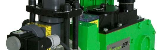
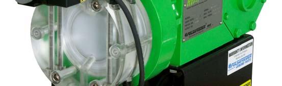
7 6. Overall System Diagram \ Figure 1 The ADV consists of a pressure balanced valve which opens periodically to allow fluid from the discharge line to bypass the discharge check valve and flow back into the pump head. The valve is actuated by a solenoid controlled by a solid-state timer. The ADV Valve Assembly incorporates a dual sealing design to insure the valve function even if the Primary Bellows seal fails. The Leak Detection Port (1/8 NPTF) allows visual indication of a Bellows failure while allowing the ADV to keep functioning. At the discretion of the user, this port may be used to pipe any leakage to a safe vessel or a leak detection device. 3
8 7. Installation 7.1 Location Review the Safety section prior to installing the pump with ADV. It contains information required to properly install and operate the ADV in an industrial environment. Review the PULSAR or PULSAR Shadow Installation Operation Maintenance manual provided with your metering pump. It details system related issues that are important to proper operation of the pump and also the ADV. The ADV should be mounted in an area where the operator has access to the front of the unit. Avoid locations where the ADV would be subjected to extreme cold or heat. Note the warning statement on the next page. The installation of this device must comply with national, state and local codes. Allow 6 inches minimum clearance from the front of the ADV enclosure to allow for removal and re-installation of the ADV as a unit. AVOID LOCATIONS WHERE THE ADV WOULD BE SUBJECTED TO EXTREME COLD OR HEAT OR DIRECT SUNLIGHT. FAILURE TO OBSERVE THIS WARNING COULD DAMAGE THE ADV AND VOID ITS WARRANTY MINIMUM OPERATING TEMPERATURE MAXIMUM (PVC CONSTRUCTION) 0 CELSIUS / 32 FAHRENHEIT 49 CELSIUS / 120 FAHRENHEIT MAXIMUM (PVDF CONSTRUCTION) 65 CELSIUS / 150 FAHRENHEIT 7.2 Installation Notes 1. Do not make any electrical connections without adequate grounding. 2. Conduit connections can carry fluids and vapors into the ADV causing damage and voiding the warranty. Care should be taken when installing conduit to protect against fluid/vapor entry. If necessary, provide sealed entries or conduit drains near the point of entry. 3. It is recommended that the ADV be powered from a Ground Fault Circuit Interrupter (GFCI) protected electrical circuit. 7.3 Electrical Wiring The ADV is available in two voltages, and is rated as follows: 115 VAC, 50/60 Hz, 0.2 A OR 230 VAC, 50/60 Hz, 0.1 A The ADV voltage is indicated on the enclosure label. 4
9 Install wiring to the unit using a minimum of 18 inches of flexible conduit or cable attached to the auto valve assembly in order to facilitate removal of the valve assembly from the reagent head for cleaning or maintenance. Wiring must conform to all applicable codes. Prior to pump startup; always check to ensure that the ADV voltage and frequency matches that of the power supply. It is recommended that the ADV be powered from a Ground Fault Circuit Interrupter (GFCI) protected electrical circuit. 1. Remove the enclosure front cover. Note: The plastic screw hole plugs can be pried out using a flat bladed tool. 2. Bring AC power and ground wires into valve assembly enclosure through the 7/8 diameter hole in the side of the enclosure. Use #18 AWG 105 degree C insulation wire size minimum. Connect per the wiring diagram. The wiring diagram is also reproduced on a label affixed to the back of the enclosure cover. Wiring Diagram 3. Apply power to the valve assembly with or without the pump running. Verify that the solenoid mounted on the pump reagent head clicks every 30 seconds. 4. Reattach cover and replace plastic hole plugs over screws. 2

10 8. Description and Operation 8.1 Principle of Operation Reciprocating metering pumps are used with a wide variety of chemicals, such as sodium hypochlorite, that produce gas within the piping and pump systems. This gas can accumulate in the pump reagent head, causing the pump to air bind and lose prime. The Auto De-gas Valve (ADV) prevents this by allowing a small amount of pressurized fluid from the discharge line to bleed back into the pump head, thereby helping to keep the pump head primed and also displacing gas through the discharge check valve. The system also has a Manual Override Button to enable faster pump priming at pump startup or other situations. 8.2 General Description The PULSAR and PULSAR Shadow HypoPump system consists of the pump reagent head, suction and discharge valves, and Auto De-gas Valve (ADV). The ADV consists of a pressure balanced valve which opens periodically to allow fluid from the discharge line to bypass the discharge check valve and flow back into the pump head. The valve is actuated by a solenoid controlled by a solid-state timer. This pre-set timer will operate properly in the majority of HypoPump applications. Power supply required is 115 or 230 VAC, 50 or 60 hz. All electrical components are enclosed in a NEMA 4X (IP 65) enclosure, which is isolated from the pumped fluid. The timer is preset at the factory to open for 0.25 seconds every 30 seconds in order to achieve optimum gas handling time with minimal pump capacity loss. The valve assembly is easily removed from the pump head in order to access the discharge check valve for cleaning or replacement. The automatic valve assembly can be run independently of the pump motor and/or controls. 8.3 Operation of Manual Override Button The Manual Override Button functions as a fast priming aid. For best results depress the button 1 second every few seconds. Do not hold the button down continuously. Depress the button 1 second every few seconds Figure 4 6

 CAUTION: Take all precautions to prevent environmental and personnel exposure to hazardous materials.")
11 9. Maintenance 9.1 Maintenance Notes The O-ring seals used in the check valve and ADV are critical to product containment and pump operation. All o-rings should be inspected carefully and any that show signs of damage or wear should be replaced. The owner may wish to replace these seals any time the ADV assembly is removed from the pump. A complete cartridge seal assembly is available to the owner as a separate repair part. If necessary, the complete ADV assembly is available as a repair item. 9.2 Auto De-gas Valve Seal Kit Replacement (NP ) CAUTION: Take all precautions to prevent environmental and personnel exposure to hazardous materials. Any product being pumped will be released during this procedure. 1. Disconnect the power source to the pump drive motor and ADV. 2. Relieve all pressure from the piping system and follow safety requirements for contact / exposure to the fluid being pumped. 3. Remove Cap Nut from front of solenoid and slide off solenoid. 4. Loosen and remove the Union Nut. At this point fluid being pumped may be released from the assembly. 5. Remove Core Tube Assembly. 7
 and")


12 6. Remove outer spring from Core Assembly (Seal Kit Assembly) and pull Core Assembly out. 7. Inspect Valve Body for O-rings that may have been left in and remove. Locate and remove both O-rings 8. Remove the sleeve from the Core Tube and remove the O-ring. 9. Locate parts from the Seal Kit. Inspect Seal Kit parts and insure the small spring is in the core. CAUTION: Do not unscrew any part of the seal kit during inspection or reassembly. Any change in length will affect valve performance. 8


13 10. Install NEW O-ring onto core tube, lubricate with lubricant that is compatible with product being pumped, and reinstall sleeve over Core Tube. 11. Install NEW O-ring on Seal Kit and with lubricant that is compatible with product being pumped. 12. Apply a lubricant that is compatible with product being pumped to the Body O-ring and install into Valve Body. 13. Install NEW Seal Kit into Valve Body. Use care to ONLY push straight into bore. 14. Install New spring over Core and check that Small Spring is still in the Core. Check that small spring is inserted in Core 9


14 15. Slide Core Tube over core and align to the tabs on the Valve Body. 16. Slide Union Nut over Core Tube and tighten onto Body. Do not over tighten, hand tight is sufficient. 17. Slide the solenoid over the Core Tube and secure with Cap Nut. Hand Tight. 18. Reapply power to the pump and ADV and follow standard startup instructions from IOM supplied with pump. 9.3 Valve Body and Discharge Valve Assembly Removal CAUTION: Take all precautions to prevent environmental and personnel exposure to hazardous materials. Any product being pumped will be released during this procedure. The O-ring seals used in the check valve and ADV are critical to product containment and pump operation. All o-rings should be inspected carefully and any that show signs of damage or wear should be replaced. The owner may wish to replace these seals any time the ADV assembly is removed from the pump. 1. Disconnect the power source to the pump drive motor. If you plan to maintain the ADV itself, remove power from the ADV unit. For maintenance to the check valves only, the ADV need not be disconnected. 2. Relieve all pressure from the piping system. 3. Close the inlet and outlet shutoff valves. 4. Take all precautions to prevent environmental and personnel exposure to hazardous materials. 10
15 5. Loosen the suction valve tiebar bolts and shift the suction piping slightly to drain any liquid from the reagent head cavity. If the piping is closely connected it may be necessary to disconnect a union or flange. 6. Loosen the tiebar bolts on the discharge valve and shift the piping slightly to drain any liquid. 7. Slide the valve assembly away from the front of the reagent head. Take care to not let the check valve parts fall out of the bottom of the valve assembly as it is removed from the reagent head. 8. Once the ADV is separated, the discharge check valve components can be removed from the assembly and cleaned or replaced. 9. Installation is the reverse of the above procedure. Be sure that the oval shaped o-ring on the bottom of the valve assembly is in the proper position when reinstalling the valve assembly. 10. Troubleshooting Guide Symptom Probable Cause Possible Solution Pump does not prime (product side) Low pump delivery Leak detection port shows leakage Valve fails to actuate Purge relay not operational Valve not actuating Check valves fouled or damaged Power interruption Valve stuck open Check valves fouled or damaged. Calibration or testing error ADV Valve fouled Failed Bellows Seal Power interruption Crystallized product in valve assembly Verify power is present at timing relay. Verify power is present at Valve Solenoid and there is a clicking noise every 30 seconds. Clean or replace suction and/or discharge check valves as per pump IOM. Check that power is connected to the ADV Clean or replace Seal Kit. Clean or replace suction and/or discharge check valves as per pump IOM. Evaluate cause and correct Clean or replace Seal Kit Install New Seal Kit Verify power is present at Valve Solenoid and there is a clicking noise every 30 seconds. Clean or replace Seal Kit. 11

16 12 PS-IOM-HYPO A
Installation Operation Maintenance ADDENDUM BULLETIN No. PS-IOM-HYP-0203-H
 Installation Operation Maintenance ADDENDUM BULLETIN No. PS-IOM-HYP-0203-H USER NOTE: This addendum serves as additional information for Pulsafeeder PULSAR and PULSAR Shadow metering pumps equipped with
Installation, Operation & Maintenance Supplement Instruction. Bulletin No.: IOMS-PUL PULSA Series 7120V DRIVE MOTOR INSTALLATION
 Installation, Operation & Maintenance Supplement Instruction Bulletin No.: IOMS-PUL-1012 PULSA Series 7120V DRIVE MOTOR INSTALLATION Copyright 2001-2015 Pulsafeeder, Inc. All rights reserved. ii Conventions
Installation, Operation and Maintenance Manual
 Installation, Operation and Maintenance Manual Manual Polymer Makedown Systems Manufacturers of Quality Pumps, Controls, and Systems Standard Product Operations 27101 Airport Rd., Punta Gorda, FL 33982
Installation Operation Maintenance Instruction
 Installation Operation Maintenance Instruction Bulletin #: PR IOM 0802 - D Hydraulic Diaphragm Metering Pump PULSAR Factory Service Policy Should you experience a problem with your PULSAR pump, first consult
Installation, Operation & Maintenance Manual. Bulletin: IOM-PUL-1500-Rev.E PULSAR HYDRAULIC DIAPHRAGM METERING PUMPS
 Installation, Operation & Maintenance Manual Bulletin: IOM-PUL-1500-Rev.E PULSAR HYDRAULIC DIAPHRAGM METERING PUMPS PULSAR FACTORY SERVICE POLICY Should you experience a problem with your PULSAR pump,
F-4600 INLINE ULTRASONIC FLOW METER Installation and Operation Guide
 F-4600 INLINE ULTRASONIC FLOW METER Installation and Operation Guide 11451 Belcher Road South, Largo, FL 33773 USA Tel +1 (727) 447-6140 Fax +1 (727) 442-5699 1054-7 / 34405 www.onicon.com sales@onicon.com
Installation, Operation, & Maintenance Instruction. Bulletin #: IOM-PN-LCM D
 Installation, Operation, & Maintenance Instruction Bulletin #: IOM-PN-LCM-0403- D Manufacturers of Quality Pumps, Controls and Systems ENGINEERED PUMP OPERATIONS 2883 Brighton Henrietta Townline Road Rochester,
PulsaPro XAE. Installation, Operation & Maintenance Manual NEMA 4X, 7 STROKE LENGTH ACTUATOR. Bulletin: IOM-CTL-XAE-2007 REV B
 PulsaPro XAE NEMA 4X, 7 STROKE LENGTH ACTUATOR Installation, Operation & Maintenance Manual Bulletin: IOM-CTL-XAE-2007 REV B AE FACTORY SERVICE POLICY Your XAE is a state of the art microprocessor-based
Updated: October 2012
 T: (630) 794-5100 EMERGENCY POWER FUEL SYSTEMS Earthsafe Systems, Inc. 7320 S. Madison Willowbrook, IL 60527 F: (630) 794-5106 info@earthsafe.com www.earthsafe.com Updated: October 2012 The information
INSTALLATION OPERATION MAINTENANCE INSTRUCTION. BULLETIN No IOM-2000 Rev. C i. Hydraulic Diaphragm Metering Pump
 INSTALLATION OPERATION MAINTENANCE INSTRUCTION BULLETIN No. 9490-IOM-2000 Rev. C 9490 i Hydraulic Diaphragm Metering Pump PULSA SERIES GUARANTEE Should you experience a problem with your Pulsafeeder pump,
DC Variable Speed Drive Panel
 DC Variable Speed Drive Panel Installation, Operation & Maintenance Instruction Manual Bulletin #: CC-IOM-0103-D Manufacturers of Quality Pumps, Controls and Systems ENGINEERED PUMP OPERATIONS 2883 Brighton
Installation, Operation, & Maintenance Instruction. Model DC7. Bulletin #: IOM-DC C
 Installation, Operation, & Maintenance Instruction Model DC7 Bulletin #: IOM-DC7-0407- C Manufacturers of Quality Pumps, Controls, and Systems STANDARD PUMP OPERATIONS 27101 Airport Road Punta Gorda, FL
Owners Manual: - Pumps
 Owners Manual: - Pumps GENERAL SAFETY RULES 1. The products mentioned in this manual are specially designed for the pre-filtering and re-circulation of water in swimming pools and spas. 2. They are designed
SmartBob AO. BinMaster: Division of Garner Industries 7201 N. 98th St., Lincoln, NE
 BinMaster: Division of Garner Industries 7201 N. 98th St., Lincoln, NE 68507 402-434-9102 email: info@binmaster.com www.binmaster.com OPERATING INSTRUCTIONS PLEASE READ CAREFULLY 925-0312 Rev B TABLE OF
Installation, Operation & Maintenance Manual. Models: GLM7 PULSA GLM MECHANICAL DIAPHRAGM METERING PUMP. Bulletin: IOM-GLM-5001-Rev.
 Installation, Operation & Maintenance Manual Models: GLM7 Bulletin: IOM-GLM-5001-Rev.B PULSA GLM MECHANICAL DIAPHRAGM METERING PUMP Pulsafeeder Factory Service Policy Should you experience a problem with
Levalarm Gold. Installation, Operation, & Maintenance Instructions R500.E253A 03/16/2016
 Installation, Operation, & Maintenance Instructions R500.E253A 03/16/2016 Levalarm Gold STORAGE AND HANDLING The Reliance Levalarm Gold meets or exceeds all applicable specifications when shipped from
ONYX VALVE CO MODEL DAO-ADA Installation & Maintenance
 ONYX VALVE CO MODEL DAO-ADA Installation & Maintenance OPERATION: (4-2010) The Onyx DAO-ADA pinch valve is an open frame valve without housing enclosure and fails last position on loss of air. This actuator
ONYX VALVE CO MODEL DAO-PFC Installation & Maintenance
 ONYX VALVE CO MODEL DAO-PFC Installation & Maintenance OPERATION: (4-2010) The Onyx DAO-PFC pinch valve is an open frame valve without housing enclosure and fails closed on loss of air. The actuator drives
LIQUIDYNAMICS Light Viscosity Bulk Transfer Cart
 This manual contains important warnings and information. READ AND KEEP FOR REFERENCE. LIQUIDYNAMICS Light Viscosity Bulk Transfer Cart Instruction & Parts Manual This Manual Covers P/N 33271 P/N 33271
Instructions for Installing and Operating Clark Reliance EA100 Series Levalarm
 Section: R500.532F Bulletin: 532F Date: 7/1/2015 Supersedes: 532E Instructions for Installing and Operating Clark Reliance EA100 Series Levalarm This manual covers the following model numbers: EA100D,
1000 Series Piston Type Differential Pressure Gauges
 1000 Series Piston Type Differential Pressure Gauges 1. Safety Before installing, check the Series Number and verify compatibility to the process media and temperature in contact with the wetted parts.
ACHL Series Pump. Operation and Maintenance Manual Air Driven, Hand Operated High Pressure Liquid Pump
 ACHL Series Pump Operation and Maintenance Manual Air Driven, Hand Operated High Pressure Liquid Pump Catalog: 02-9245ME February 2013 Model # Serial # Drawing # Order # Mfg. Date Table of Contents page
BULLETIN No.: PulsaPro 900-IOM-2009 Rev. J PulsaPro Control Addendum INSTALLATION OPERATION MAINTENANCE INSTRUCTIONS
 BULLETIN No.: PulsaPro 900-IOM-2009 Rev. J PulsaPro Control Addendum INSTALLATION OPERATION MAINTENANCE INSTRUCTIONS Manufacturers of Quality Pumps, Controls and Systems Pulsafeeder, Inc. 2883 Brighton
Sentry Battery Charger. Installation and Operations Manual Section 75
 Sentry Battery Charger Installation and Operations Manual 00-02-0616 03-03-08 Section 75 In order to consistently bring you the highest quality, full featured products, we reserve the right to change our
IMPORTANT SAFETY NOTICE
 IMPORTANT SAFETY NOTICE To: Our Valued Customers User safety is a major focus in the design of our products. Following the precautions outlined in this manual will minimize your risk of injury. ITT Goulds
RP-4000 Reserve Power Control
 Instruction Manual IM-0580 RP-4000 Reserve Power Control Table of Contents General Information... 2-3 Introduction... 2 Cautions... 2 Receiving/Inspection... 2 Storage... 2 Equipment Return... 2 Identification
Operating Instructions - Electric Pow'r-Riser Models
 ADivisionOf Templeton, Kenly& Co., Inc. Operating Instructions - Electric Pow'r-Riser Models Table of Contents 1.0 Recieving Instructions 2.0 Safety 3.0 Specifications 4.0 Initial Installation Before Operating
DIGITAL GLYCOL FEEDER
 DIGITAL GLYCOL FEEDER DGF1, DGF2 OPERATING INSTRUCTIONS P/N: 72-900-24 Rev J (06-22-07) Manufactures of Quality Pumps, Controls and Systems STANDARD PUMP OPERATION 27101 Airport Road Punta Gorda, FL 33982
Mounting and Operating Instructions EB 8135/8136 EN. Series V2001 Valves Type 3535 Three-way Valve for Heat Transfer Oil
 Series V2001 Valves Type 3535 Three-way Valve for Heat Transfer Oil Type 3535 Three-way Valve with bellows seal and rod-type yoke (partial view) Mounting and Operating Instructions EB 8135/8136 EN Edition
P239-1 Supply Pumper Instructions
 P239-1 Supply Pumper Instructions STOP! READ THIS SECTION NOW. The following information is critical to the proper installation and operation of this Oil Supply System! Read it carefully before starting
Corrosion Coupon Rack
 Corrosion Coupon Rack INSTALLATION & OPERATION MANUAL 72-912-00 1 Revision C Table of Contents 1 Cautions and Warnings... 2 2 Temperature to Pressure Ratings... 3 3 Installation... 4 4 Operation... 5 5
SELF PRIMING CHEMICAL SERVICE PUMPS
 SELF PRIMING CHEMICAL SERVICE PUMPS INSTALLATION AND OPERATING INSTRUCTIONS This Manual covers: SELF PRIMING MODEL RANGE J50ECX TO J250ECX STAINLESS STEEL*, and NON METALLIC SEAL PUMP MODEL: SERIAL NO:
Matrix AP 400V 690V INSTALLATION GUIDE. Quick Reference. ❶ How to Install Pages 6 20 ❷ Startup/Troubleshooting Pages WARNING
 Matrix AP 400V 690V INSTALLATION GUIDE FORM: MAP-IG-E REL. May 2017 REV. 002 2017 MTE Corporation WARNING High Voltage! Only a qualified electrician can carry out the electrical installation of this filter.
Installation & Operating Manual
 Installation & Operating Manual 25INV-M 1/17 Edition NV Series Vertical Booster Stainless Steel Multistage Centrifugal Pump Congratulations On Your Choice In Purchasing This Webtrol Pump Its Quality is
Installation, Operation & Maintenance Manual. Bulletin: IOM-PSRM-1501 REV B. PULSAR Shadow MECHANICAL DIAPHRAGM METERING PUMP
 Installation, Operation & Maintenance Manual Bulletin: IOM-PSRM-1501 REV B PULSAR Shadow MECHANICAL DIAPHRAGM METERING PUMP PULSAR Factory Service Policy Should you experience a problem with your PULSAR
PENBERTHY MODELS GL AND GH GAS OPERATED JET PUMPS INSTALLATION, OPERATION AND MAINTENANCE INSTRUCTIONS
 Before installation, these instructions must be read carefully and understood. PRODUCT WARRANTY Emerson warrants its Penberthy products as designed and manufactured to be free of defects in the material
Pneumatic Isolation Module
 Pneumatic Isolation Module (Cat. 2030-Pxxxxx) ATTENTION: Hazardous Voltage or other forms of energy could be present. To avoid serious injury or death: Prior to beginning the installation and wiring process,
Drilling Series SC Series Cellular Suction Stabilizers Instruction, Operating & Maintenance Manual
 Drilling Series SC Series Cellular Suction Stabilizers Instruction, Operating & Maintenance Manual Manufacturer of Pulsation Control Products 3309 Essex Dr. Suite 200, Richardson, Texas 75082 Phone: 972.699.8600
ONYX VALVE CO MODEL DAO-PFO Installation & Maintenance
 ONYX VALVE CO MODEL DAO-PFO Installation & Maintenance OPERATION: (4-2010) The Onyx DAO-PFO pinch valve is an open frame valve without housing enclosure and fails open on loss of air. The actuator drives
MAINTENANCE MANUAL FOR THERMOSTATIC TEMPERATURE REGULATING VALVE TRAC STYLE P
 MANUAL NUMBER P-EFS-1 MAINTENANCE MANUAL FOR THERMOSTATIC TEMPERATURE REGULATING VALVE TRAC STYLE P TRAC Regulator Company Inc. 160 South Terrace Avenue Mount Vernon, New York USA 10550-2408 Phone: (914)
High Frequency SineWave Guardian TM
 High Frequency SineWave Guardian TM 380V 480V INSTALLATION GUIDE FORM: SHF-IG-E REL. January 2018 REV. 002 2018 MTE Corporation High Voltage! Only a qualified electrician can carry out the electrical installation
DO NOT INSTALL, OPERATE, OR MAINTAIN AN ATI PRODUCT UNLESS TRAINED AND QUALIFIED IN PRODUCT AND ACCESSORY INSTALLATION, OPERATION AND MAINTENANCE.
 IOM Supplement IOMS003 ATI HO1/HO2 HYDRAULIC OVERRIDE Scope of Supplement This supplement is intended to assist those who are involved with the installation, operation and maintenance of ATI Linear Actuators
INSTALLATION GUIDE AND USER MANUAL
 Electric Vehicle Charging Station INSTALLATION GUIDE AND USER MANUAL Model: 30A EVoCharge EVSE Model Number: EV072-300-001A Product Safety Certification: UL and cul Listed Description: SAE J1772 AC Level
Dimensions 12/800N 12/1200N D. DC to AC Power Inverters. OWNERS MANUAL for Models: OWNERS MANUAL April ISO 9001:2000 Certified Company
 Manufacturer of Dimensions Inverters 4467 White Bear Parkway St. Paul, MN 55110 Phone: 651-653-7000 Fax: 651-653-7600 E-mail: inverterinfo@sensata.com Web: www.dimensions.sensata.com OWNERS MANUAL April
AGV5-1, AGV5-2 FORM AGV5 OM 11-02
 ALTRONIC GAS FUEL VALVE OPERATING MANUAL AGV5-1, AGV5-2 FORM AGV5 OM 11-02 WARNING: DEVIATION FROM THESE INSTALLATION INSTRUCTIONS MAY LEAD TO IMPROPER ENGINE OPERATION WHICH COULD CAUSE PERSONAL INJURY
Installation and Operating Manual
 Model u002 & u003 Installation and Operating Manual Ultrasonic Level Switch 60 Great Hill Road Naugatuck, CT 06770 ph: 203-729-6434 fax: 203-729-6696 www.innovativesensing.com Read this Manual Before Installing
Model 550 Series Vibration Switches
 OPERATION MANUAL Vibration Switches Includes: 550 550M 550-X 550M-X Page 2 SECTION TITLE PAGE 1. INTRODUCTION... 2 2. FEATURES... 3 3. WIRING... 4 4. ANALOG METER... 4 5. TESTING... 4 6. INSTALLATION...
U00X ULTRASONIC LEVEL SWITCH. Ultrasonic Liquid Level Switches INSTALLATION AND OPERATIONS MANUAL. For Models: U002, U003 & U004
 U00X ULTRASONIC LEVEL SWITCH INSTALLATION AND OPERATIONS MANUAL Ultrasonic Liquid Level Switches For Non-Hazardous Locations For Models: U002, U003 & U004 READ THIS MANUAL PRIOR TO INSTALLATION This manual
Purging Air From Divider Block Lubrication Systems
 FROST ENGINEERING SERVICE Purging Air From Lubrication Systems A D I V I S I O N O F G E C S E Y S A L E S & S E R V I C E DESCRIPTION Divider block lubrication systems operate correctly only when all
INSTALLATION, OPERATION, AND MAINTENANCE MANUAL WELKER INJECTION PUMP
 INSTALLATION, OPERATION, AND MAINTENANCE MANUAL WELKER INJECTION PUMP MODEL SSO-8 DRAWING NUMBERS AD148CF AD148CG AD148CO AD148CQ AD500CA MANUAL NUMBER IOM-065 REVISION Rev. A, 8/17/2016 TABLE OF CONTENTS
U00X ULTRASONIC LEVEL SWITCH. Ultrasonic Liquid Level Switches INSTALLATION AND OPERATIONS MANUAL. For Models: U002, U003 & U004
 U00X ULTRASONIC LEVEL SWITCH INSTALLATION AND OPERATIONS MANUAL Ultrasonic Liquid Level Switches For Non-Hazardous Locations For Models: U002, U003 & U004 READ THIS MANUAL PRIOR TO INSTALLATION This manual
Installation, Operation, and Maintenance Manual
 Intelligent Flow Measurement Your Sole Source for Badger Differential Producers Worldwide 6 Blackstone Valley Place, Lincoln RI 02865-1162 Ph: 401 334 1170 Fx: 401 334 1173 Em: solutions@wyattflow. Installation,
dv Sentry TM 208V 600V INSTALLATION GUIDE Quick Reference ❶ How to Install Pages 6 14 ❷ Startup/Troubleshooting Pages WARNING
 dv Sentry TM 208V 600V INSTALLATION GUIDE FORM: DVS-IG-E REL. January 2018 REV. 003 2018 MTE Corporation High Voltage! Only a qualified electrician can carry out the electrical installation of this filter.
Mounting and Operating Instructions EB 8053 EN. Series 250 Type and Type Pneumatic Control Valves
 Series 250 Type 3252 1 and Type 3252 7 Pneumatic Control Valves Type 3252 High-pressure valve with Type 3277 Pneumatic Actuator and Type 3767 Electropneumatic Positioner Mounting and Operating Instructions
Dispenser Pan Sensors & Containment Sump Sensors
 Manual No: 576013-306 Revision: G Dispenser Pan Sensors & Containment Sump Sensors Installation Guide Notice Veeder-Root makes no warranty of any kind with regard to this publication, including, but not
Keystone Series GR resilient seated butterfly valves GRW/GRL Installation and operation manual
 Before installation these instructions must be fully read and understood Important Before valves are installed or used the following actions are recommended. 1. Valves/parts have to be inspected and thoroughly
Manual No: Revision: B. CCVP Rain Shield. Installation Guide
 Manual No: 577013-978 Revision: B CCVP Rain Shield Installation Guide Notice Veeder-Root makes no warranty of any kind with regard to this publication, including, but not limited to, the implied warranties
Model LA 4400 Time Delay OFF Controller
 ISIMET LA Series Model LA 4400 Time Delay OFF Controller Installation, Operation and Maintenance Manual Application: The Time Delay OFF Controller with integral 24-hr. programmable time clock operates
NorthStar. brand. Instruction Manual. SLIM Tach SL Thru-Shaft Diameter. Magnetoresistive Encoder Designed for GE Wind Energy
 NorthStar TM brand Instruction Manual SLIM Tach SL56 1.125 Thru-Shaft Diameter Magnetoresistive Encoder Designed for GE Wind Energy Patent Pending *791-1061-00* Rev. B Page 2 Table of Contents Chapter/Paragraph/Illustration
Safety Clamp Operation Manual
 TECHNICAL MANUAL Safety Clamp Operation Manual 2005-2016 Texas International Oilfield Tools, LTD. Published by Texas International Oilfield Tools, LTD, Engineering 14620 Henry Road. Houston, TX 77060 www.texasinternational.com
SEPARATOR PURGE KIT OPERATION & MAINTENANCE MANUAL
 SEPARATOR PURGE KIT OPERATION & MAINTENANCE MANUAL PLEASE RECORD THE FOLLOWING DATA (Information is located on the product label or packing slip) Model Number: Service: Code: Installation Date: Installation
PERISTALTIC DOSING PUMP OPERATING MANUAL. MODEL: FS SERIES Fixed Speed Peristaltic Pump
 PERISTALTIC DOSING PUMP OPERATING MANUAL MODEL: FS SERIES Fixed Speed Peristaltic Pump 6012 33 RD Street East Bradenton, FL 34203 800-446-2656 1 TABLE OF CONTENTS FS SERIES PUMP SPECIFICATIONS... 3 FS
Rental Industry Safety Tester Safe Check 5s
 Rental Industry Safety Tester Safe Check 5s Feb 2006 2006 Clare Instruments Inc. Issue 2.0 Firmware Version : 1.2a Limited Warranty & Limitation of Liability Clare Instruments Inc, guarantees this product
Val-Matic Air / Oil Hydraulic Panel Pump Control System. Operation, Maintenance and Installation Manual
 Manual No. 5AOP-OM1-2 Val-Matic Air / Oil Hydraulic Panel Pump Control System Operation, Maintenance and Installation Manual INTRODUCTION... 1 RECEIVING AND STORAGE... 1 DESCRIPTION OF OPERATION... 1 INSTALLATION...
MIL-24/2600Q MIL-24/3200DQ
 Manufacturer of Dimensions TM Inverters 4467 White Bear Parkway St. Paul, MN 55110 Phone: 651-653-7000 Fax: 651-653-7600 E-mail: inverterinfo@sensata.com Web: www.dimensions.sensata.com 121473B OWNER'S
SineWave Guardian TM 380V 600V INSTALLATION GUIDE. Quick Reference. ❶ How to Install Pages 6 17 ❷ Startup/Troubleshooting Pages WARNING
 SineWave Guardian TM 380V 600V INSTALLATION GUIDE FORM: SWG-IG-E REL. October 2018 REV. 003 2018 MTE Corporation High Voltage! Only a qualified electrician can carry out the electrical installation of
NECO Pumping Systems
 INSTALLATION OPERATION & MAINTENANCE INSTRUCTIONS For Your NECO Pumping Systems PACKAGED CIRCULATING SYSTEM THIS COMPLETELY ASSEMBLED, TESTED, PACKAGED CIRCULATING SYSTEM IS OF THE HIGHEST QUALITY AND
BMRX Series ROTARY LEVEL CONTROL
 BMRX Series ROTARY LEVEL CONTROL OPERATING INSTRUCTIONS PLEASE READ CAREFULLY 925-0292 Rev C TABLE OF CONTENTS GENERAL SPECIFICATIONS... 3 SAFETY SUMMARY... 4 1.0 INTRODUCTION... 5 2.0 INSTALLATION...
Full View Flow Indicator
 Full View Flow Indicator Threaded and Flanged Process Connection Installation / Operation / Maintenance Manual P.O. Box 1116 Twinsburg, OH 44087 Phone: 330/405-3040 Fax: 330/405-3070 E-mail: view@ljstar.com
Model LA 4100 Time Delay OFF Controller
 ISIMET LA Series Model LA 4100 Time Delay OFF Controller Installation, Operation and Maintenance Manual Application: The Time Delay OFF Controller operates as a single output controller where the application
Shock/Vibration Control Switches
 Shock/Vibration Control Switches Models: VS2, VS2C, VS2EX, VS2EXR, VS2EXRB and VS94 ` Installation Instructions 00-02-0185 2013-02-01 Section 20 Please read the following information before installing.
COSASCO HYDRAULIC ACCESS FITTING User Manual
 COSASCO HYDRAULIC ACCESS FITTING User Manual Rohrback Cosasco Systems, Inc. 11841 E. Smith Avenue Santa Fe Springs, CA 90670 Tel: (562) 949-0123 (800) 635-6898 Fax: (562) 949-3065 E-mail: sales@cosasco.com
Eaton Battery Charger Module Models ASY-0652 and ASY-0675 User s Guide
 Eaton 9170 + Battery Charger Module Models ASY-0652 and ASY-0675 User s Guide Class A EMC Statements FCC Part 15 NOTE This equipment has been tested and found to comply with the limits for a Class A digital
Rosemount 402 and 402VP
 Rosemount 402 and 402VP Contacting Conductivity Sensors Instruction Manual LIQ-MAN-402 Rev. M May 2017 hasgkas Essential Instructions Read this page before proceeding! Emerson designs, manufactures and
DuraMAC LIGHT COMMERCIAL & IRRIGATION WATER PRESSURE BOOSTER SYSTEM INSTALLATION INSTRUCTIONS
 DuraMAC LIGHT COMMERCIAL & IRRIGATION WATER PRESSURE BOOSTER SYSTEM INSTALLATION INSTRUCTIONS The DuraMAC TM Water Pressure Booster System is the first booster pump of its kind to be designed for virtually
Series 72 Electri-SAFE On/Off Operation Including CLC Option Installation, Operation and Maintenance Instructions
 WCAIM2049 (Part 18960) Series 72 Electri-SAFE On/Off Operation Including CLC Option Installation, Operation and Maintenance Instructions Series 72 actuators are electro-hydraulic quarterturn valve actuators.
INSTRUCTION MANUAL INSTALLATION, OPERATION, AND MAINTENANCE ACTUATOR MANIFOLD
 INSTRUCTION MANUAL INSTALLATION, OPERATION, AND MAINTENANCE B-3724M ACTUATOR MANIFOLD MIDLAND MANUFACTURING CORP. 7733 Gross Point Road Skokie, Illinois 60077 Phone (847) 677-0333 FAX (847) 677-0138 WEBSITE
USER MANUAL. NEMA 48C Flange Mounted, Enclosed, Clutch Brake. FMCBE Model 500 FORM NO. L A (i)
") USER MANUAL NEMA 48C Flange Mounted, Enclosed, Clutch Brake FMCBE Model 500 (i) In accordance with Nexen s established policy of constant product improvement, the specifications contained in this manual
USER MANUAL NEMA 48C Flange Mounted, Enclosed, Clutch Brake FMCBE Model 500 (i) In accordance with Nexen s established policy of constant product improvement, the specifications contained in this manual
PART B BRAND SPECIFIC MANUAL
 SPA OWNER S MANUAL IMPORTANT SAFETY INSTRUCTIONS PART B BRAND SPECIFIC MANUAL ELECTRICAL CONNECTION KEYPAD OPERATION 200 Series 200-M-B-16 Read in conjunction with Part A General Manual to form a complete
55185 EMERGENCY PACK FOR LED PANEL TECHNICAL DATA SHEET
 FEATURES SPECIFICATIONS Power Consumption 10W Output Voltage 18~59Vdc MAX Input Current 500 ma Emergency Time 90 Minutes Battery Specification 14.4V/2000mAH Dimension (Inches) 12.6 (L) x 1.8 (W) x 1.3
Electric Vehicle Charging Station
 EVoReel Electric Vehicle Charging Station INSTALLATION GUIDE AND USER MANUAL Model: Dual Output Pedestal Mount 30A EVoReel EVSE Model Numbers: With Basic EVSE: EV072-400-002A; With Intelligent ievse: EV072-410-002A;
Installation, Operation and Maintenance Manual
 Installation, Operation and Maintenance Manual Manual & Dry Contact Polymer Makedown Systems Manufacturers of Quality Pumps, Controls, and Systems Standard Product Operations 0 Airport Rd., Punta Gorda,
INSTALLATION AND SERVICE MANUAL FOR TURBO-CARB HIGH CAPACITY CARBONATOR
 Please refer to the Lancer web site (www.lancercorp.com) for information relating to Lancer Installation and Service Manuals, Instruction Sheets, Technical Bulletins, Service Bulletins, etc. INSTALLATION
OPERATING INSTRUCTIONS PLEASE READ CAREFULLY
 OPERATING INSTRUCTIONS PLEASE READ CAREFULLY 925-0330 Rev 0 0416 TABLE OF CONTENTS SAFETY SUMMARY... 3 SPECIFICATIONS... 4 1.0 INTRODUCTION/DESCRIPTION.... 5 2.0 LOCATION AND MOUNTING... 5 3.0 CONNECTIONS
G72x Series Direct Spark Ignition Controls
 Installation Sheets Manual 121 Gas Combustion Combination Controls and Systems Section G Technical Bulletin G72x Issue Date 1299 G72x Series Direct Spark Ignition Controls Figure 1: G72x Direct Spark Ignition
Model LA 4300 Time Delay OFF Controller
 ISIMET LA Series Model LA 4300 Time Delay OFF Controller Installation, Operation and Maintenance Manual Application: The Time Delay OFF Controller operates as a single output controller where the application
Installation, Operation, Repair and Parts Manual
 Self-Priming Adaptor Form L-1516 (3-08) Installation, Operation, Repair and Parts Manual Description Self-priming adaptor (SPA) is a low pressure tank that provides air separation from the liquid being
High Lift Flange Weld/Test Plug (3/4"-8") - Technical Specifications
 - Technical Specifications") EXPANSION SEAL TECHNOLOGIES DC8055 11/98 REV 4 03/05 High Lift Flange Weld/Test Plug (3/4"-8") - Technical Specifications Flange Size Ansi Flange Class Pipe Schedule Part Number Plug OD Seal to Pipe Pipe
EXPANSION SEAL TECHNOLOGIES DC8055 11/98 REV 4 03/05 High Lift Flange Weld/Test Plug (3/4"-8") - Technical Specifications Flange Size Ansi Flange Class Pipe Schedule Part Number Plug OD Seal to Pipe Pipe
CompoSeal butterfly valves, wafer style Installation & Maintenance Instructions
 Please read these instructions carefully This symbol indicates important messages and safety instructions. Intended valve use The valve is intended to be used only in applications within the pressure/temperature
CP (Vdc) CP (Milliamp) CP (Slidewire)
 CP (Milliamp) CP (Slidewire)") CP-91-456 (Vdc) CP-91-716 (Milliamp) CP-91-717 (Slidewire) Electronic General Instructions Application Electronic actuator drive is used to provide proportional control of an electric gear train actuator
CP-91-456 (Vdc) CP-91-716 (Milliamp) CP-91-717 (Slidewire) Electronic General Instructions Application Electronic actuator drive is used to provide proportional control of an electric gear train actuator
Keystone Butterfly valves ParaSeal Installation and maintenance instructions
 Before installation these instructions must be fully read and understood Please read these instructions carefully Hazard potentials: disregarding of instructions improper use of product insufficiently
Installation Instructions. Y-Series Brushless Servo Motor
 Installation Instructions Y-Series Brushless Servo Motor Catalog Number Y-1002-1, Y-1002-2, Y-1003-1, Y-1003-2, Y-2006-1, Y-2006-2, Y-2012-1, Y-2012-2, and Y-3023-2 These installation instructions describe
FastPrep FP120 Cell Disrupter INSTRUCTION MANUAL
 FastPrep FP120 Cell Disrupter INSTRUCTION MANUAL Applies to FP100, FP120, and FP220 Models Qbiogene, Inc. (North America) 2251 Rutherford Road Carlsbad, CA 92008 Phone (800) 424-6101 Fax (760) 918-9313
General Installation Instructions for Valves and Gates
 General Installation Instructions for Valves and Gates Thank you for your purchase of a Lorenz valve. We appreciate your business! Please read this installation manual and follow recommended safety precautions.
Micro-Air Corporation Route 526 Allentown, NJ 08501
 EasyStart 366 Commercial (board-only) Model ASY-366-X05 (36000 BTU, 3 ton) ASY-366-X06 (72000 BTU, 6 ton) Micro-Air Corporation www.microair.net 124 Route 526 help@microair.net Allentown, NJ 08501 Contents
Revision A
 Remanufactured 82-90XL Pinspotter Safety Guard Kit Installation Manual 400-082-001 Revision A 82-90XL Pinspotter Safety Guard Kit Installation Manual, 400-082-001, Rev. A Summary of Changes Change No.
100 Gallon Skid Sprayer
 100 Gallon Skid Sprayer Model #: KS100P17 User Manual Read this manual for complete instructions Model #: KS100P17 Table of Contents Warranty... 3 General Safety Information... 3 Hazardous Substance Alert...
INSTALLATION GUIDE AND USER MANUAL
 Electric Vehicle Charging Station INSTALLATION GUIDE AND USER MANUAL SAE J1772 AC Level 2 EVSE Model: 30A EVoCharge EVSE Wall Mount P/N: EV072-300-001A Version 2.0 IMPORTANT Read this manual thoroughly
BOILER BLOWDOWN CONDUCTIVITY CONTROLLER (CONTINUOUS METHOD)
") LAKEWOOD INSTRUMENTS MODEL 260 SERIES BOILER BLOWDOWN CONDUCTIVITY CONTROLLER (CONTINUOUS METHOD) INSTALLATION & OPERATION MANUAL SERIAL #: Lakewood Instruments 7838 North Faulkner Road, Milwaukee, WI
LAKEWOOD INSTRUMENTS MODEL 260 SERIES BOILER BLOWDOWN CONDUCTIVITY CONTROLLER (CONTINUOUS METHOD) INSTALLATION & OPERATION MANUAL SERIAL #: Lakewood Instruments 7838 North Faulkner Road, Milwaukee, WI
INSTALLATION/OPERATION/MAINTENANCE INSTRUCTIONS FOR ARCHON MODELS WD2010L, WD2010, WD2010H WASHDOWN STATIONS. ARCHON Industries, Inc.
 ARCHON Industries, Inc. Washdown Stations Models WD2010L, WD2010, WD2010H Installation / Operation / Maintenance Instructions 1 This manual has been prepared as an aid and guide for personnel involved