Installation, Operation, & Maintenance Instruction. Model DC7. Bulletin #: IOM-DC C
|
|
|
- Kelley Harrison
- 5 years ago
- Views:
Transcription


1 Installation, Operation, & Maintenance Instruction Model DC7 Bulletin #: IOM-DC C Manufacturers of Quality Pumps, Controls, and Systems STANDARD PUMP OPERATIONS Airport Road Punta Gorda, FL (941) Fax (941)
2 Pulsafeeder Factory Service Policy Should you experience a problem with your Pulsafeeder pump, first consult the troubleshooting guide in your operation and maintenance manual. If the problem is not covered or cannot be solved, please contact your local Pulsafeeder Sales Representative or Distributor, or our Technical Services Department for further assistance. Trained technicians are available to diagnose your problem and arrange a solution. Solutions may include purchase of replacement parts or returning the unit to the factory for inspection and repair. All returns require a Return Authorization number to be issued by Pulsafeeder. Parts purchased to correct a warranty issue may be credited after an examination of original parts by Pulsafeeder. Warranty parts returned as defective which test good will be sent back freight collect. No credit will be issued on any replacement electronic parts. Any modifications or out-of-warranty repairs will be subject to bench fees and costs associated with replacement parts. Safety Considerations: 1. Read and understand all related instructions and documentation before attempting to install or maintain this equipment 2. Observe all special instructions, notes, and cautions. 3. Act with care and exercise good common sense and judgment during all installation, adjustment, and maintenance procedures. 4. Ensure that all safety and work procedures and standards that are applicable to your company and facility are followed during the installation, maintenance, and operation of this equipment. Revision History: Rev A (4-07) - First Release Rev B (8-07) - Updated lubricating oil specification and part numbers - Add instruction to fill with oil prior to storage - Minor text revisions Rev C (1-09) - Added Duplex Dimensional and BOM Copyright 2007 Pulsafeeder, Inc. All rights reserved. Information in this document is subject to change without notice. No part of this publication may be reproduced, stored in a retrieval system or transmitted in any form or any means electronic or mechanical, including photocopying and recording for any purpose other than the purchaser s personal use without the written permission of Pulsafeeder, Inc. 2
3 Table of Contents 1. INTRODUCTION PRINCIPLES OF OPERATION Reagent Head Assembly Control Assembly Gear Ratio Assembly EQUIPMENT INSPECTION STORAGE INSTALLATION Location Piping System Suction Pressure Requirements Discharge Pressure Requirements EQUIPMENT STARTUP Fastener Inspection Output Adjustment Oil Fill and Maintenance Priming the Reagent Head Calibration MAINTENANCE Diaphragm Removal & Reinstallation Diaphragm Shaft Seal Check Valves Check Valve Removal & Reinstallation, Plastic Union-Nut type Check Valve Removal and Reinstallation, Metal Tie-Bar type Motor Removal & Reinstallation REPLACEMENT PARTS KOPkit Program Ordering KOPkits or Parts KOPkit numbers by model: MODEL NUMBER IDENTIFICATION WET END MATERIALS REFERENCE TROUBLESHOOTING PIPING ACCESSORIES DIMENSIONAL DRAWING PARTS DIAGRAMS AND PARTS LISTS


4 1. Introduction The OMNI metering pump is positive displacement, mechanically operated reciprocating diaphragm pump. Each pump consists of a power end and a process end separated by a Teflon faced diaphragm. Individual pumps will vary in appearance due to various liquid ends and accessories; however, the basic principles of operation remain the same. 2. Principles Of Operation Figure 1, reagent head operation A diaphragm reciprocates at a preset stroke length, displacing an exact volume of process fluid. Diaphragm retraction causes the product to enter through the suction check valve. Diaphragm advance causes the discharge of an equal amount of the product through the discharge check valve. 4
5 2.1 Reagent Head Assembly The typical reagent head assembly consists of reagent head, diaphragm, and suction and discharge cartridge check valves. This assembly is the only part of the pump to contact the process liquid; consequently, maintenance is critical to pump performance. 2.2 Control Assembly The OMNI pump incorporates a full motion style of stroke length adjustment. The stroke length setting is indicated by a (0% 100%) scale located on the stroke adjustment assembly. Stroke length is changed by loosening the locking screw and turning the hand knob. This turns a mechanism, which changes the amplitude of the stroke length. As the stroke adjustment knob is turned towards 100%, it displaces the cam eccentrically to the rotating drive shaft. This in turn causes the pushrod and diaphragm to travel over a longer distance. Refer to Section 6.2 for further information. For automatic flow rate control, users can consider the Pulsafeeder MPC speed based control system, please contact your local Pulsafeeder dealer or representative for more information. 2.3 Gear Ratio Assembly OMNI pumps are driven by an electric motor mounted on the motor adaptor input flange. The motor drives a set of worm gears that convert rotational speed into torque. They, in turn, power the eccentric shaft assembly that converts rotary motion into reciprocating motion. The gear assembly and eccentric shaft run submerged in a lubricating oil bath. Figure 2, isometric view 5
6 3. Equipment Inspection Check all equipment for completeness against the order and for any evidence of shipping damage. Shortages or damage must be reported immediately to the carrier and your authorized representative or distributor of OMNI pumps. 4. Storage Short Term Storage of your OMNI pump for up to 12 months is considered short-term. The recommended short-term storage procedures are: a) Store the pump indoors at room temperature in a dry environment. b) The lubricating oil should be added to the gearbox prior to storage c) If required by the operating environment, take precautions to prevent entry of water or humid air into the eccentric enclosure. d) Prior to startup, perform a complete inspection and then start up in accordance with instructions in this manual Long Term Every twelve months, in addition to the above short-term procedures, power up the motor and operate the pump for a minimum of one hour. It is not necessary to have liquid in the reagent head during this operation, but the suction and discharge ports must be open to atmosphere. After twelve months of storage, Pulsafeeder s warranty cannot cover items that are subject to deterioration with age, such as seals, gaskets, and diaphragms. If the pump has been in storage longer than 12 months it is recommended that these items be inspected and replaced as necessary prior to startup. Lubricating oil should also be changed prior to startup. Materials and labor to replace this class of item under this circumstance are the purchaser s responsibility. Consult your local Pulsafeeder representative for assistance in obtaining parts and service for your pump. 5. Installation 5.1 Location When selecting an installation site or designing a chemical feed system, consideration should be given to access for routine maintenance. OMNI pumps are designed to operate indoors and outdoors, but it is desirable to provide a hood or covering for outdoor service. External heating is required if ambient temperatures below 0 C (32 F) are anticipated, especially if pumps are not in continuous duty. Check with the factory if concerned with the suitability of the operating environment. The pump must be rigidly bolted to a solid and flat foundation to minimize vibration, which can loosen connections. When the pump is bolted down, care must be taken to avoid distorting the base and affecting alignments. The pump must be level within 5. This will assure that the check valves can operate properly. 6
7 5.2 Piping System 1. All systems should include a pressure relief valve on the discharge side, to protect piping and process equipment, including the pump, from excess process pressures. An external relief valve is required! There should be no devices capable of restricting flow (such as a valve) located between the pump and the relief device. 2. Shutoff valves and unions (or flanges) on suction and discharge piping are recommended. This permits check valve inspection without draining long runs of piping, making periodic maintenance and inspection easier. Shutoff valves should be of the same size as connecting pipe. Ball valves are preferred since they offer minimum flow restriction. 3. Suction systems should include an inlet strainer, if appropriate for the product being pumped. Pump check valves are susceptible to dirt and other solid contaminants, and any accumulation can cause malfunction. The strainer should be located between the suction shutoff valve and the pump suction valve. It must be sized to accommodate the flow rate and the anticipated level of contamination. A 100 mesh screen size is generally recommended. 4. Vacuum/pressure gauges in the suction and discharge lines are helpful in order to check system operation. Gauges should be fitted with protective shutoff valves for isolation while not in use. 5. Piping weight must not be supported by valve housings or other portions of the reagent head, as the resulting stresses can cause leaks. If appropriate, provide for thermal expansion and contraction so that no excess force or moments are applied to the pump. 6. In piping assembly, use a sealing compound chemically compatible with the process material. Users of sealing tape are cautioned to ensure that the entering pipe thread ends are not taped, and that tape is removed from previously-used threads to the maximum practical extent prior to re-use. Both new and existing piping should be cleaned, preferably by flushing with a clean liquid (compatible with process material) and blown out with air, prior to connection to the pump. Debris from the piping system that prevents proper check valve operation is a common startup issue. 5.3 Suction Pressure Requirements Although OMNI metering pumps have some suction lift capability, a flooded suction (i.e., suction pressure higher than atmospheric pressure) is preferable whenever possible. The pump should be located as close as possible to the suction side reservoir or fluid supply source. For fluid with a vapor pressure of 5 psia or less (at operating temperature) the wet suction lift capability is approximately ten (10) feet. If this requirement is not met, the pump will not provide reliable, accurate flow. In suction lift conditions, the use of a foot valve is recommended at the lowest point of the pickup tube or pipe. Pumps under suction lift conditions may require some liquid priming before they will operate reliably. For long suction lines, and also for pumps that have a high stroking rate, the largest possible suction line diameter should be used to provide best suction conditions. In some cases, the proper line size may exceed the suction connection size on the pump. Consult your local Pulsafeeder Representative for assistance and further information on proper suction system design. 7
8 5.4 Discharge Pressure Requirements All OMNI metering pumps are designed for continuous service at the rated discharge pressure. If system suction pressure exceeds discharge pressure (a condition sometimes described as pumping downhill ), flow would be generated (siphoning) in addition to that caused by the pump. This results in a reduction in accuracy and loss of control over the metering process. To prevent this flow-through condition, the discharge pressure must exceed suction pressure by at least 0.35 Bar (5 psi). This can be achieved where necessary by the installation of a backpressure valve in the discharge line. Conditions where the actual discharge pressure exceeds the pump s rating are to be avoided as they will cause damage to the pump components. Figure 3, sample system configuration 8
9 6. Equipment Startup 6.1 Fastener Inspection All pump fasteners should be checked prior to pump operation, and occasionally during use. This would include reagent head mounting bolts, motor mounting bolts, and the hardware that secures the pump to its foundation. Most hardware can be checked simply to ensure it is not loose. However, utilize the following values when checking reagent head bolt torque: Model DC7 Material Reagent Head Bolt Torque # Bolts and size N-m In. - Lbs Plastic (8) M10 * Metal (8) M10 * Output Adjustment All OMNI pumps have a hand wheel for manual stroke adjustment. The hand wheel can be adjusted to any point from 0 to 100%. This value represents the stroke length setting and therefore the flow rate of the pump relative to its maximum output. 1. Turn the red lock screw counterclockwise to release the stroke lock. Making adjustments without releasing the lock may damage the mechanism. Figure 4, stroke adjustment knob and scale 2. Adjust the hand wheel to the desired output. a) The stroke barrel indicates stroke length in 20% increments. b) The hand wheel indicates stroke length in 0.25% increments. For example, to set the pump to 75% stroke length, (starting from the factory default setting of 0%) turn the hand wheel clockwise until the 60% indicator on the stroke barrel is aligned with the edge of the knob at the 0 position on the knob scale. Continue the clockwise rotation until the hand wheel indicator passes zero again (this is 70%) and comes to 5, this is 75%. Refer to Figure Turn the lock screw clockwise to lock the stroke adjustment into position. Adjustments can be made while the pump is at rest or operating, although adjustments are easier to make while the pump is in operation. 9
10 6.3 Oil Fill and Maintenance Oil Capacities It is recommended that adequate supplies of PulsaLube oil be on hand for periodic changes and emergency requirements. The approximate amounts of oil required to fill the OMNI DC7 pump to specified levels are: Pump Capacity PulsaLube EP Gear Oil Gearbox, Model DC7 2,500 ml (2.6 Qt) Pulsafeeder Part No. Description Container Size NP PulsaLube EP Gear Oil 500 ml NP PulsaLube EP Gear Oil 1 liter NP PulsaLube EP Gear Oil 2.5 liter NP PulsaLube EP Gear Oil 18 liter Gearbox Oil Fill Fill the gearbox with oil by removing the threaded oil fill cap on the top of the pump. Fill with the proper oil (PulsaLube EP Gear Oil) to the upper edge of the sight glass on the side of the pump. Replace the cover or controller. Replace the oil fill cap. See figure 5. Note that during operation, the oil should be visible at the middle of the sight glass. Figure 5, oil filler cap and sight glass 10
11 6.3.3 Oil Changes The recommended oil change intervals are dependent upon the operating environment and level of pump usage, classified as follows: Normal service: Clean/dry atmosphere, an ambient operating temperature of 0 0 C to 40 0 C (32 0 F to F) and up to 2,000 annual operating hours. Severe Service: Humid atmosphere, an ambient operating temperature below 0 0 C (32 0 F) or above 40 0 C (104 0 F), and over 2,000 annual operating hours. The recommended eccentric oil change interval is two (2) years for normal service and one (1) year for severe service. The procedure is as follows: 1. Disconnect the power source to the drive motor 2. Relieve all pressure from the piping system. 3. Remove the fill plug from the top of the pump gearbox. 4. Drain the oil by removing the drain plug on the bottom of the gearbox, opposite the stroke adjustment knob. 5. Replace the drain plug. 6. Fill the eccentric box with PulsaLube oil as described under Gearbox Oil Fill. 7. Replace the fill plug and double check that the drain plug is secure. 6.4 Priming the Reagent Head 1. When handling process liquids, follow all applicable personal and facility safety guidelines. 2. Ensure that the pump is ready for operation and that all process connections are secure. 3. Open the suction and discharge line shutoff valves. 4. If the piping system design and the storage tank are such that the product flows due to gravity through the pump, reduce the discharge pressure and the system will self prime when the pump is started. In the event the discharge line contains a significant amount of pressurized air or other gas, it may be necessary to lower the discharge pressure to enable the pump to self-prime. 5. If the installation involves a suction lift, it may be necessary to prime the reagent head and suction line. Operate the pump as in step 4 above, many times the pump will be capable of self priming. If it does not begin to pump, remove the discharge valve assembly. Carefully fill the reagent head through the discharge valve port with process (or compatible) liquid, and then reinstall the check valve. 11

 above. Use appropriate precautions if handling process fluid.")
12 6. Start the pump at the zero stroke length setting and slowly increase the setting to 100 to prime the pump. If this does not work, it will be necessary to fill the suction line. 7. Filling of the suction line will necessitate the use of a foot valve or similar device at the end of the suction line so that liquid can be maintained above the reservoir level. Remove the suction valve assembly, fill the line, replace the suction valve, then remove the discharge valve assembly and fill the reagent head as described in Step (3) above. The pump will now self-prime when started up per step (4) above. Use appropriate precautions if handling process fluid. Ensure that any other fluid used for priming is compatible with the product that will be pumped. Figure 6, process flow 12
13 6.5 Calibration Figure 7, sample flow calibration curve All metering pumps must be calibrated to accurately specify stroke length settings for required flow rates. A typical calibration chart is shown above. Although output is linear with respect to stroke length setting, an increase in discharge pressure decreases output uniformly, describing a series of parallel lines, one for each pressure (only two are shown). The theoretical output flow rate at atmospheric discharge pressure is based on the displacement of the diaphragm, stroke length and the stroking rate of the pump. With increasing discharge pressure there is a corresponding decrease in output flow. Pumps are rated for a certain flow at a rated pressure (check nameplate). Whenever possible, calibration should be performed under actual process conditions (i.e., the same or a similar process liquid at system operating pressure). To construct a calibration chart, measure the flow rate several times at three or more stroke settings (i.e., 25, 50, 75, and 100), plot these values on linear graph paper, and draw a best-fit line through the points. For stable conditions, this line should predict settings to attain required outputs. All users are encouraged to test the flow rate of their pump once installed in their system, to ensure best accuracy and reliable operation. 13
14 7. Maintenance BEFORE PERFORMING ANY MAINTENANCE REQUIRING REAGENT HEAD OR VALVE (WET END) DISASSEMBLY, BE SURE TO RELIEVE PRESSURE FROM THE PIPING SYSTEM AND, WHERE HAZARDOUS PROCESS MATERIALS ARE INVOLVED, RENDER THE PUMP SAFE TO PERSONNEL AND THE ENVIRONMENT BY CLEANING AND CHEMICALLY NEUTRALIZING AS APPROPRIATE. WEAR PROTECTIVE CLOTHING AND EQUIPMENT AS APPROPRIATE. Accurate records from the early stages of pump operation will indicate the type and levels of required maintenance. A preventative maintenance program based on such records will minimize operational problems. It is not possible to forecast the lives of wetted parts such as diaphragms and check valves. Since corrosion rates and operational conditions affect functional material life, each metering pump must be considered according to its particular service conditions. The OMNI KOPkit will contain all replacement parts normally used in a preventative maintenance program. It is recommended that KOPkits and PulsaLube EP Gear Oil be kept available at all times. IF THE DIAPHRAGM HAS FAILED, PROCESS FLUID MAY HAVE CONTAMINATED THE PUMP ECCENTRIC HOUSING (ALTHOUGH NORMALLY, ANY PROCESS FLUID BEHIND A FAILED DIAPHRAGM WOULD PASS THROUGH THE BOTTOM DRAIN HOLE). HANDLE WITH APPROPRIATE CARE. 14

15 Figure 8, wet end components OMNI diaphragms do not have a specific cycle life; however, the accumulation of foreign material or debris sufficient to deform the diaphragm can eventually cause failure. Failure can also occur as a result of system over pressure or chemical attack. Periodic diaphragm inspection and replacement are recommended. Each user should perform regular inspections to determine the replacement interval that is appropriate to their system conditions. 15
16 7.1 Diaphragm Removal & Reinstallation 1. Adjust the stroke setting to 0% and disconnect the power source to the drive motor. 2. Relieve all pressure from the piping system. Take all precautions described under the WARNINGS on page 14, Section 7 to prevent environmental damage and exposure of personnel to hazardous materials. 3. Close the inlet and outlet shutoff valves. 4. Place a pan underneath the pump head adaptor to catch any liquid leakage. 5. Note the orientation of the existing check valve components. Loosen the union nuts holding the check valves and piping to the reagent head. Remove the check valve assemblies, drain and rinse them, and set them aside in a safe place. Unscrew the union nuts completely from the regent head. Figure 9, wet end components 16
17 6. Remove all but one top reagent head bolt. Product will leak out between the pump head adaptor and reagent head as the bolts are loosened. 7. Remove the final bolt and rinse or clean the reagent head with an appropriate material. 8. Insert a screwdriver or similar tool through the oil fill hole and into the hole provided in the pushrod, this will keep the pushrod from turning as the diaphragm is removed. Note that depending on pushrod position, you may have to rotate the motor coupling or the diaphragm to access the hole. Figure 10, securing pushrod 9. Remove the diaphragm by turning it counter-clockwise. 10. Inspect the diaphragm. The diaphragm must be replaced if it is cracked, separated, or obviously damaged. 11. Install the diaphragm. a) Ensure that the critical sealing areas of diaphragm, reagent head, and pump head are clean and free of debris. b) Lubricate the elastomer side of the diaphragm liberally, where it is in contact against the pump head and deflection plate. Use a silicone grease or silicone-based o-ring lubricant. c) Coat the threads and the end of the pushrod with an anti-seize paste or lubricant. 17
18 12. Thread the diaphragm (clockwise) fully onto the shaft. When reinstalling a used diaphragm it is not necessary to maintain the previous orientation relative to the reagent head or pump head hole pattern. 13. Remove the screwdriver from the oil fill hole and replace the cap. 14. Install the reagent head bolts and tighten in an alternating pattern to ensure an even seating force. Torque to the values recommended in Section Reassemble the piping connections and check valves to the reagent head, using care to orient all check valve parts properly (refer to figures 9 and 12). 16. Re-prime the pump following the procedure outlined in Section Diaphragm Shaft Seal While the diaphragm is removed, inspect the shaft seal located in the pump head. If there is evidence of damage or wear and/or oil leakage, the seal should be replaced. 1. Remove the three retainer screws and the seal retainer. 2. Pry the old seal out of the retainer. 3. Ensure the surfaces of the retainer are clean and clean of debris, scratches, or burrs. 4. Insert the new seal into the retainer by hand, do not use tools to prevent damage to the seal. 5. Inspect the piston shaft and remove any scratches, burrs, or surface corrosion or damage. 6. Lubricate the shaft with a small amount of pump oil. 7. Slide the seal and retainer back into position and secure with the three screws. Figure 11, piston shaft seal replacement 18

19 7.3 Check Valves Most fluid metering problems are related to check valves. Problems usually stem from solids accumulation between valve and seat, corrosion of seating surfaces, erosion, or physical damage due to wear or the presence of foreign objects. The valve incorporates a ball, guide, and seat. Flow in the unchecked direction lifts the ball off the seat, allowing liquid to pass through the guide. Reverse flow forces the ball down, sealing it against the sharp edge of the seat. The guide permits the ball to rotate but restricts vertical and lateral movement in order to minimize slip or reverse flow. Ball rotation prolongs life by distributing wear over the entire surface of the ball. Since ball return is by gravity, the valve must be in the vertical position in order to function properly. Parts are sealed by O -rings. OMNI DC7 pumps utilize a multi-part check valve assembly, secured to the reagent head with a union nut clamping arrangement (plastic construction) or a tie-bar arrangement (metal construction). Figure 12, check valves DC7 19
20 7.4 Check Valve Removal & Reinstallation, Plastic Union-Nut type 1. Disconnect the power source to the drive motor. 2. Relieve all pressure from the piping system, and take all precautions necessary to prevent contamination to the environment and personnel exposure to hazardous materials. 3. Close the inlet and outlet shutoff valves. 4. Loosen the union nuts that hold the check valves in place. It is not necessary to completely remove the nut. 5. Push the check valve assembly out of the front by inserting your finger or a tool into the clearance hole at the back of the holder. Note carefully the position of the component parts, to assist in reassembly. Be aware that product may leak out as the check valve parts are removed. 6. Replace both valve assemblies onto the pump, taking care to ensure they are oriented correctly, with the balls above the seats, and the seats oriented with the o-ring seat facing up and the chamfered edge down. The check assemblies must be pushed into the holder until they stop against the back surface. Replace parts with new as required. Sealing o-rings should generally be replaced even if the check components are re-used. Figure 13, union-nut type check valve Inserting the check valve assembly into the pump in the wrong directiom, or having the check seat upside down, will prevent proper seals at the o-rings, decrease pump performance, and can cause damage to the diaphragm. Each union nut should be tightened only until the o-ring seal makes good contact. 7. Carefully make sure that the check assemblies are in proper position, and tighten the union nuts. 8. Retighten any unions, flanges, or other process connections that may have been loosened previously. 20
21 7.5 Check Valve Removal and Reinstallation, Metal Tie-Bar type 1. Disconnect the power source to the drive motor. 2. Relieve all pressure from the piping system. 3. Take all precautions necessary to prevent contamination to the environment and personnel exposure to hazardous materials. 4. Close the inlet and outlet shutoff valves. 5. Loosen the suction valve tie-bar bolts (4) and spring the suction piping slightly away from the head, allowing liquid to drain. It may be necessary to loosen a union or flange. 6. Remove the suction check valve assembly by sliding it towards you, holding it together as a unit. Note carefully the position of the component parts, to assist in re-assembly. 7. Loosen the discharge valve tie-bar bolts (4) and spring the discharge piping slightly away from the head, allowing liquid to drain. It may be necessary to loosen a union or flange. 8. Remove the discharge check valve assembly by sliding it towards you, holding it together as a unit. Note carefully the position of the component parts, to assist in re-assembly. 9. Disassemble both valves and check components for wear or damage. The seats should have a sharp edge and be free from dents or nicks. Hold a ball firmly against the seat in front of a bright light and inspect for fit, observation of light between the ball and seat is cause for replacement. 10. Reassemble both valves using new parts as required. Sealing o-rings should always be replaced. 11. Replace both valve assemblies onto the pump, taking care to ensure they are oriented correctly, with the balls above the seats, and the seats oriented with the sharp edge up and the chamfered edge down. Inserting the check valve assembly into the pump in the wrong directiom, or having the check seat upside down, will prevent proper seals at the o-rings, decrease pump performance, and can cause damage to the diaphragm. 12. Carefully make sure that the check assemblies are in proper position, and tighten the four tie-bar bolts, using a star pattern, to a torque of 6 Ft-lbs (8 N-m). 13. Retighten any unions, flanges, or other process connections that may have been loosened previously. 21


22 Figure 14, Check valves, metal construction 22

23 7.6 Motor Removal & Reinstallation 1. Disconnect the power source to the drive motor. 2. Disconnect the motor wiring from the motor. 3. Remove the four bolts retaining the motor to the motor adaptor. Lift the motor upwards away from the pump. 4. Apply an anti-seize paste or lubricant to all bolts, setscrews, and keys before reassembling.. 5. Reinstall the motor in the reverse from removal. 6. Insert and tighten the four bolts removed in step Reconnect the motor wiring to the motor. 8. Connect power to the drive motor. Motor rotation must be wired for CW rotation, as viewed from the top of the motor, as noted by the arrow on the top of the pump housing. Figure 15, motor mounting 23
24 8. Replacement Parts 8.1 KOPkit Program OMNI KOPkits contain all replacement parts normally used in a preventative maintenance program. (PULSAlube oil is also available separately for preventative maintenance programs. Refer to Section 6 Equipment Startup). There is a specific KOPkit for every OMNI pump model. Each KOPkit is vacuum-packed for extended storage. All OMNI pumps have the KOPkit number identified on the pump nameplate and Pulsafeeder order documents. KOPkits can also be selected from the technical data sheet shipped with the pump or by a Pulsafeeder representative. A list of the OMNI KOPkit numbers can also be found on the next page. The kit is identified by the model number of the pump, the wetted end material, and the process connection thread type. For models with tie-bar type check valves, the appropriate components (check valve balls, seats, and o-rings) are supplied instead of the cartridges pictured. 8.2 Ordering KOPkits or Parts When ordering replacement parts always specify: Figure 16, KOPkit parts Pump model and serial number (from pump nameplate), e.g., Model No. (DC7) with Serial No. F Part number and description from the OMNI parts list. Include the three-character suffix. (Note: OMNI part numbers begin either with the letters NP, or the letter W, e.g., NP THY or W ) 24
25 8.3 KOPkit numbers by model: NOTES: Pump Model Wetted Material Connection Type KOPkit number DC7 PVDF NPT / ISO / FLG NLK070X DC7 Polypropylene NPT / ISO / FLG NLK070X DC7 316 (future use) DC7 HSO (1) (future use) (1) HSO construction refers to the recommended materials for handling Sulfuric Acid at high concentrations (above 95%). This configuration consists of 316ss for the reagent head, the valve guide, and the process connection. Alloy-20 is supplied for the check valve seats, and Hastelloy-C is supplied for the check valve balls. HS0 configuration is supplied only as a KOPkit and not as an original pump configuration. (2) DC2 through 6 models are covered in a separate publication (3) PVDF and Polypropylene KOPkits are identical as only balls and insert o-rings are supplied 9. Model Number Identification Position Sample Specifies Options 1 and 2 DC DC = OMNI model pump 3 and 4 7C Size/Flow 7 diaphragm diameter C / D stroking rate See sales literature for flow/pressure ratings 5 1 Motor frame 1 IEC 90 Frame and size 2 IEC 100 Frame 3 NEMA 56C Frame 4 NEMA 143/145TC Frame 6 F Wetted materials F PVDF, Viton o-rings, ceramic ball P - Polypro, Viton o-rings, ceramic ball 7 X Motor Supplied X No motor purchased with pump M Pump purchased with motor 25
26 10. Wet End Materials Reference Wet End Configuration PVDF (Kynar ) PP (Polypropylene) SS (316) Model Connection Head Guide DC2 DC3 DC4 DC5 DC6 DC7 DC2 DC3 DC4 DC5 DC6 DC7 1/4" NPT 1/2" NPT or ISO 7-1 1" NPT or ISO /2" NPT & ANSI Flange and DIN40 Flange n/a PVDF PVDF Sealing O-rings Balls Seats Seat O- ring PTFE PVDF n/a Viton Ceramic n/a PVDF (oring seat) Viton (1) 1" NPT or I ISO 7-1 PTFE PP n/a 1 1/2" NPT & ANSI Flange and DIN40 Flange PP PP Viton Ceramic PP (o-ring seat) DC2 1/4" NPT Ceramic PTFE DC3 1/2" NPT or ISO 7-1 DC4 SS SS PTFE SS SS DC5 1" NPT or ISO 7-1 DC6 DC7 n/a Viton (1) n/a (1) DC7 check valve seats incorporate an o-ring seal DC2 through 6 models are covered in a separate publication n/a = materials not available in this pump size or component not used on this model 26
27 11. Troubleshooting Difficulty Probable Cause Remedy Pump does not start No delivery Low delivery Delivery gradually drops. Delivery erratic. Delivery higher than rated. Faulty power source. Blown fuse, circuit breaker. Broken wire. Wired improperly. Process piping blockage. Motor not running. Supply tank empty. Lines clogged. Closed line valves. Ball check valves held open with solids. Vapor lock, cavitation. Prime lost. Strainer clogged. Stroke adjustment set at zero. Motor speed too low Check valves worn or dirty Calibration system error Product viscosity too high Product cavitating Check valve leakage. Leak in suction line. Strainer fouled. Product change. Supply tank vent plugged. Leak in suction line. Product cavitating. Entrained air or gas in product. Motor speed erratic. Fouled check valves. Inadequate backpressure Suction pressure higher than discharge pressure. Back pressure valve set too low. Back pressure valve leaks. Check power source. Replace - eliminate overload. Locate and repair. Check diagram. Open valves, clear other obstructions. Check power source. Check wiring diagram (see above). Fill tank. Clean and flush. Open valves. Clean inspect, flush with clear fluid. Increase suction pressure. Re-prime, check for leak. Remove and clean. Replace screen if necessary. Increase stroke length setting. Check voltages, frequency, wiring, and terminal connections. Check nameplate vs. Specifications. Clean, replace if damaged Evaluate and correct Lower viscosity by increasing product temperature or dilution. Increase pump and/or piping size Increase suction pressure. Clean, replace if damaged. Locate and correct. Clean or replace screen. Check viscosity and other variables. Unplug vent. Locate and correct. Increase suction pressure. Consult factory for suggested venting. Check voltage and frequency. Clean, replace if necessary. Increase discharge pressure to obtain a minimum pressure difference of 5 pis from suction to discharge Install backpressure valve or consult factory for piping recommendations. Increase setting. Repair, clean, or replace. 27
28 Difficulty Probable Cause Remedy Noisy gearing, knocking Piping noisy. Motor overheats. Discharge pressure too high. Water hammer. Low oil level. Pipe size too small. Pipe runs too long. Pulsation dampener inoperative or flooded. No surge chamber or dampener used. Pump overloaded. High or low voltage. Loose wire. Incorrect motor wiring Oil level low Reduce pressure. Install pulsation dampener. Examine sight glass on side of pump Add or replace oil as required Increase size of piping - install pulsation dampener. Install pulsation dampener in line. Refill with air or inert gas. Inspect and replace diaphragm and recharge. Install pulsation dampeners. Check operating conditions against pump design. Verify discharge pressure Check power source. Trace and correct. Verify and correct Check and add as necessary 28
29 12. Piping Accessories Pressure Relief Valves Pressure relief valves are designed to protect chemical feed systems from damage that may be caused by defective equipment or a blockage in the discharge line. These valves function to limit the pressure downstream of the pump. Field adjust the pressure relief valve to operate when the discharge pressure exceeds operating pressure by 10-15%. Pressure relief valve should always be adjusted to a setting below the maximum rated pressure of the pump. No potentially restrictive components, such as a valve, should be installed between the pump discharge and the PRV. Diaphragm Backpressure Valve A diaphragm backpressure valve creates constant back pressure. A PTFE or PTFE-faced diaphragm offers maximum chemical protection and service life, and seals spring and bonnet from product. Be sure to install with fluid flow in direction of arrow on valve body. Pulsation Dampener A pulsation dampener is a pneumatically charged diaphragm-type chamber that intermittently stores hydraulic energy. Used on the inlet, it can improve NPSHA (Net Positive Suction Head available) characteristics of the suction piping system. On the discharge line it will reduce discharge pressure and pulsating flow variations. 29
30 13. Dimensional Drawing 30
31 31
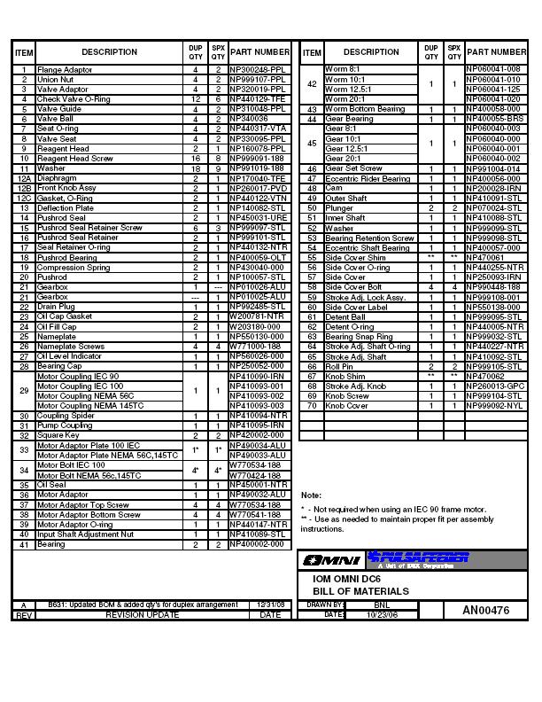
32 14. Parts Diagrams and Parts Lists 32
33 33
34 STANDARD PUMP OPERATIONS Airport Road Punta Gorda, FL (941) Fax (941) Bulletin #: IOM-DC Rev C 34
Installation, Operation, & Maintenance Instruction. Bulletin #: IOM-PN-LCM D
 Installation, Operation, & Maintenance Instruction Bulletin #: IOM-PN-LCM-0403- D Manufacturers of Quality Pumps, Controls and Systems ENGINEERED PUMP OPERATIONS 2883 Brighton Henrietta Townline Road Rochester,
Installation, Operation & Maintenance Manual. Models: GLM7 PULSA GLM MECHANICAL DIAPHRAGM METERING PUMP. Bulletin: IOM-GLM-5001-Rev.
 Installation, Operation & Maintenance Manual Models: GLM7 Bulletin: IOM-GLM-5001-Rev.B PULSA GLM MECHANICAL DIAPHRAGM METERING PUMP Pulsafeeder Factory Service Policy Should you experience a problem with
Installation Operation Maintenance Instruction
 Installation Operation Maintenance Instruction Models DC2, 3, 4, 5, and 6 sales@novatech-usa.com www.novatech-usa.com Tel: (866) 433-6682 Fax: (866) 433-6684 Tel: (281) 359-8538 Fax: (281) 359-0084 Mechanical
Installation Operation Maintenance Instruction
 Installation Operation Maintenance Instruction Bulletin #: PR IOM 0802 - D Hydraulic Diaphragm Metering Pump PULSAR Factory Service Policy Should you experience a problem with your PULSAR pump, first consult
Installation, Operation & Maintenance Manual. Bulletin: IOM-PUL-1500-Rev.E PULSAR HYDRAULIC DIAPHRAGM METERING PUMPS
 Installation, Operation & Maintenance Manual Bulletin: IOM-PUL-1500-Rev.E PULSAR HYDRAULIC DIAPHRAGM METERING PUMPS PULSAR FACTORY SERVICE POLICY Should you experience a problem with your PULSAR pump,
INSTALLATION OPERATION MAINTENANCE INSTRUCTION. BULLETIN No IOM-2000 Rev. C i. Hydraulic Diaphragm Metering Pump
 INSTALLATION OPERATION MAINTENANCE INSTRUCTION BULLETIN No. 9490-IOM-2000 Rev. C 9490 i Hydraulic Diaphragm Metering Pump PULSA SERIES GUARANTEE Should you experience a problem with your Pulsafeeder pump,
Installation, Operation & Maintenance Supplement Instruction. Bulletin No.: IOMS-PUL PULSA Series 7120V DRIVE MOTOR INSTALLATION
 Installation, Operation & Maintenance Supplement Instruction Bulletin No.: IOMS-PUL-1012 PULSA Series 7120V DRIVE MOTOR INSTALLATION Copyright 2001-2015 Pulsafeeder, Inc. All rights reserved. ii Conventions
Installation, Operation & Maintenance Manual. Bulletin: IOM-PSRM-1501 REV B. PULSAR Shadow MECHANICAL DIAPHRAGM METERING PUMP
 Installation, Operation & Maintenance Manual Bulletin: IOM-PSRM-1501 REV B PULSAR Shadow MECHANICAL DIAPHRAGM METERING PUMP PULSAR Factory Service Policy Should you experience a problem with your PULSAR
Installation Operation Maintenance ADDENDUM BULLETIN No. PS-IOM-HYP-0203-H
 Installation Operation Maintenance ADDENDUM BULLETIN No. PS-IOM-HYP-0203-H USER NOTE: This addendum serves as additional information for Pulsafeeder PULSAR and PULSAR Shadow metering pumps equipped with
Installation, Operation & Maintenance Instruction. Models: FMP Series 30, 40, 50. PeriFlo FMP PERISTALTIC PUMP. Bulletin #: IOM-PFL-4502
 Installation, Operation & Maintenance Instruction Models: FMP Series 30, 40, 50 Bulletin #: IOM-PFL-4502 PeriFlo FMP PERISTALTIC PUMP Pulsafeeder Factory Service Policy Should you experience a problem
Installation, Operation & Maintenance Manual. Models: ChemTuff Series PeriFlo ChemTuff PERISTALTIC PUMP. IOM-PFL-4600-Rev.B
 Installation, Operation & Maintenance Manual Models: ChemTuff Series 10 22 IOM-PFL-4600-Rev.B PeriFlo ChemTuff PERISTALTIC PUMP Pulsafeeder Factory Service Policy Should you experience a problem with your
Installation, Operation & Maintenance Instruction. Models: GLM M1 6 PULSA GLM MECHANICAL DIAPHRAGM METERING PUMP. Bulletin #: IOM-GLM-1303-A
 Installation, Operation & Maintenance Instruction Models: GLM M1 6 Bulletin #: IOM-GLM-1303-A PULSA GLM MECHANICAL DIAPHRAGM METERING PUMP Pulsafeeder Factory Service Policy Pulsafeeder s Factory Service
Installation Operation Maintenance ADDENDUM
 Installation Operation Maintenance ADDENDUM Bulletin #: PS-IOM-HYPO2-0111-A FACTORY SERVICE POLICY If you are experiencing a problem with your Pulsafeeder pump, first review the IOM, and consult the troubleshooting
BULLETIN No.: PulsaPro 900-IOM-2009 Rev. J PulsaPro Control Addendum INSTALLATION OPERATION MAINTENANCE INSTRUCTIONS
 BULLETIN No.: PulsaPro 900-IOM-2009 Rev. J PulsaPro Control Addendum INSTALLATION OPERATION MAINTENANCE INSTRUCTIONS Manufacturers of Quality Pumps, Controls and Systems Pulsafeeder, Inc. 2883 Brighton
INSTALLATION OPERATION MAINTENANCE INSTRUCTION
 INSTALLATION OPERATION MAINTENANCE INSTRUCTION BULLETIN No. 680C ENGINEERED PUMP OPERATIONS 2883 Brighton Henrietta TL Road P.O. Box 22909 Rochester, New York, 14692-22909 USA Telephone (716) 292-8000
Installation Operation Maintenance Instruction
 Installation Operation Maintenance Instruction Bulletin #: IOM-680 IOM-680 Rev B. i Table of Contents 1. INTRODUCTION... 1 1.1 How Things Work... 1 1.2 Hydraulically Balance Flat Diaphragm Design... 1
TWO-STAGE HYDRAULIC PUMP. RWP55-IBT-Air
 ORIGINAL INSTRUCTIONS Form No.1000458 5 SPX Corporation 5885 11th Street Rockford, IL 61109-3699 USA Tech. Services: (800) 477-8326 Fax: (800) 765-8326 Order Entry: (800) 541-1418 Fax: (800) 288-7031 Internet
1/2" AIR DRIVEN DIAPHRAGM PUMP
 1/2" DRIVEN DIAPHRAGM PUMP OPERATION AND SERVICE GUIDE O-1225D NOV. 2008 Page 1 of 6 Refer to Bulletin P-605, Parts List P-9151 DRIVEN, DOUBLE DIAPHRAGM PUMP MANUAL Congratulations on purchasing one of
PulsaPro. Installation, Operation & Maintenance Manual HYDRAULIC DIAPHRAGM METERING PUMPS. Bulletin: IOM-PRO-001
 PulsaPro HYDRAULIC DIAPHRAGM METERING PUMPS Installation, Operation & Maintenance Manual Bulletin: IOM-PRO-001 PULSAFEEDER FACTORY SERVICE POLICY Upon receipt of your new PulsaPro diaphragm metering pump,
END SUCTION CENTRIFUGAL PUMPS
 OWNERS GUIDE TO INSTALLATION AND OPERATION FW000 009 Supersedes 07 END SUCTION CENTRIFUGAL PUMPS READ THESE INSTRUCTIONS CAREFULLY Read these installation instructions in detail before installing your
An IDEX Water & Wastewater Business. pulsafeeder.com. Mechanical Diaphragm Metering Pump
 An IDEX Water & Wastewater Business pulsafeeder.com Mechanical Diaphragm Metering Pump Pulsafeeder Expertise Since 1936, Pulsafeeder has been the global leader in fluids handling technology and innovation
PULSA GLM ENGINEERED PRODUCTS. Mechanical Diaphragm. Max Flow: to 3,200 LPH (845 GPH) Pressure: 12 bar (175 psi) Temperature: 0-45 C ( F)
 Pressure: 12 bar (175 psi) Temperature: 0-45 C ( F)") ENGINEERED PRODUCTS Max Flow: to 3,200 LPH (845 GPH) Pressure: 12 bar (175 psi) Temperature: 0-45 C (32-113 F) Accuracy: +/- 2% of Set Point PULSA GLM Mechanical Diaphragm Metering Pump Mechanical Diaphragm
ENGINEERED PRODUCTS Max Flow: to 3,200 LPH (845 GPH) Pressure: 12 bar (175 psi) Temperature: 0-45 C (32-113 F) Accuracy: +/- 2% of Set Point PULSA GLM Mechanical Diaphragm Metering Pump Mechanical Diaphragm
INSTALLATION, OPERATION AND MAINTENANCE MANUAL (IOM)
") INSTALLATION, OPERATION AND MAINTENANCE MANUAL (IOM) IOM-1088 03-16 Model 1088 Vacu-Gard Blanketing Valve ISO Registered Company SECTION I I. DESCRIPTION AND SCOPE The Model 1088 Vacu-Gard is a tank blanketing
INSTALLATION, OPERATION AND MAINTENANCE MANUAL (IOM) IOM-1088 03-16 Model 1088 Vacu-Gard Blanketing Valve ISO Registered Company SECTION I I. DESCRIPTION AND SCOPE The Model 1088 Vacu-Gard is a tank blanketing
Installation, Operation and Maintenance Manual
 Installation, Operation and Maintenance Manual Manual Polymer Makedown Systems Manufacturers of Quality Pumps, Controls, and Systems Standard Product Operations 27101 Airport Rd., Punta Gorda, FL 33982
SERIES PC INSTRUCTION AND OPERATION MANUAL
 MEGGA SERIES PC INSTRUCTION AND OPERATION MANUAL Models PCT and PCF Close-coupled and frame-mounted single-stage horizontal end-suction pumps. WARNING: Read this manual before installing or operating this
Installation, Operation & Maintenance Instruction Bulletin #: IOM-NMG-0804 Rev D
 Installation, Operation & Maintenance Instruction Bulletin #: IOM-NMG-0804 Rev D Manufacturers of Quality Pumps, Controls, and Systems ENGINEERED PUMP OPERATIONS 2883 Brighton Henrietta Townline Road Rochester,
LIQUIDYNAMICS Light Viscosity Bulk Transfer Cart
 This manual contains important warnings and information. READ AND KEEP FOR REFERENCE. LIQUIDYNAMICS Light Viscosity Bulk Transfer Cart Instruction & Parts Manual This Manual Covers P/N 33271 P/N 33271
Crispin Valves Operating Guide. Crispin
 Crispin Valves Operating Guide Crispin Since 1905 Crispin Multiplex Manufacturing Co. 600 Fowler Avenue Berwick, PA 18603 1-800-AIR-VALV T: (570) 752-4524 F: (570) 752-4962 www.crispinvalve.com sales@crispinvalve.com
Air Operated Double Diaphragm Pump. M-Pump ½ Metallic Non Metallic Pump INSTALLATION, OPERATION & MAINTENANCE MANUAL
 Air Operated Double Diaphragm Pump M-Pump ½ Metallic Non Metallic Pump INSTALLATION, OPERATION & MAINTENANCE MANUAL 0.5 I.O.M rev 05. 12/2015 INDEX Title Section Introduction.1 Safety.2 Warranty, General
SERIES FE MAGNETIC COUPLED PUMPS
 SERIES FE MAGNETIC COUPLED PUMPS Refer to Bulletin P-518 O-2804 TABLE OF CONTENTS Description Page Number Important Information...3 Chemical Reaction Disclaimer...3 Safety Precautions...3 Installation/Operation
An IDEX Water & Wastewater Business. pulsafeeder.com. Electronic Metering Pump
 An IDEX Water & Wastewater Business pulsafeeder.com Electronic Metering Pump Pressure (PSI) Pressure (BAR) Pulsafeeder Expertise Technology is the key to delivering responsible products to the markets
HIGH PRESSURE CONTROL VALVE PISTON BALANCED
 PISTON BALANCED All Rights Reserved. All contents of this publication including illustrations are believed to be reliable. And while efforts have been made to ensure their accuracy, they are not to be
Installation Operation Maintenance Instruction
 Installation Operation Maintenance Instruction Bulletin #: IOM-NMG-0804 Rev F i ii Pulsafeeder Factory Service Policy Should you experience a problem with your Eclipse Standard/Eclipse Hypo Series pump,
Mechanical Diaphragm Metering Pump
 Mechanical Diaphragm Metering Pump sales@novatech-usa.com www.novatech-usa.com Tel: (866) 433-6682 Fax: (866) 433-6684 Tel: (281) 359-8538 Fax: (281) 359-0084 Pulsafeeder Expertise Since 1936, Pulsafeeder
Valtek Auxiliary Handwheels and Limit Stops
 Valtek Auxiliary s and Limit Stops Table of Contents Page 1 General information 2 Installation 2 Side-mounted handwheels, size 25 and 50 (linear actuators) 3 Side-mounted handwheels, size 100 and 200 (linear
Apollo Standard Port, Full Port & One Piece Flanged Ball Valves Installation, Operation, & Maintenance Guide
 I854000.F M16005 Apollo Standard Port, Full Port & One Piece Flanged Ball Valves Introduction This manual presents guidelines for the Installation, Operation and Maintenance of manual and automated Apollo
Model 8329 Table of Contents
 SERVICE & OPERATING MANUAL Original Instructions Instructions Sheet: 670991 Model 8329 Table of Contents Engineering Data and Temperature Limitations... 1 Performance Curve... 2 Dimensions... 3 Metric
Fluid-O-Tech ROTOFLOW ROTARY VANE PUMP REBUILD MANUAL
 Fluid-O-Tech PUMP TECHNOLOGY AT ITS BEST WWW.FLUID-O-TECH.COM Office: 161 Atwater St., Plantsville, CT 06479 Phone: (860) 276-9270 Fax: (860) 620-0193 ROTOFLOW ROTARY VANE PUMP REBUILD MANUAL 08/09 Ed.,
AIR/HYDRAULIC INJECTION GUN MODEL INSTRUCTIONS
 I. OPERATION & DESCRIPTION The Air / Hydraulic Injection Gun is a high-pressure tool that should be used with caution and according to these instructions. IMPORTANT: The Gun is 0,000 psi rated. Do not
Operating instructions Form no safety definitions
 Operating instructions Form no. 1000437 safety definitions safety symbols are used to identify any action or lack of action that can cause personal injury. Your reading and understanding of these safety
Low Profile J Series Power Unit with Vane Pump
 Low Profile J Series Power Unit with Vane Pump READ ALL INSTRUCTIONS CAREFULLY BEFORE ATTEMPTING TO ASSEMBLE, INSTALL, OPERATE OR MAINTAIN THE PRODUCT DESCRIBED. PROTECT YOURSELF AND OTHERS BY OBSERVING
MAINTENANCE MANUAL FOR THERMOSTATIC TEMPERATURE REGULATING VALVE TRAC STYLE P
 MANUAL NUMBER P-EFS-1 MAINTENANCE MANUAL FOR THERMOSTATIC TEMPERATURE REGULATING VALVE TRAC STYLE P TRAC Regulator Company Inc. 160 South Terrace Avenue Mount Vernon, New York USA 10550-2408 Phone: (914)
SERVICE PARTS LIST SPECIFY CATALOG NO. AND SERIAL NO. WHEN ORDERING PARTS 13 HP DIRECT DRIVE PRESSURE WASHER CATALOG NO
 SPECIFY CATALOG NO. AND SERIAL NO. WHEN ORDERING PARTS HP DIRECT DRIVE PRESSURE WASHER CATALOG NO. 555-22 SERVICE PARTS LIST STARTING SERIAL NUMBER B06A REVISED BULLETIN PAGE OF BULLETIN NO. 5-20-000 DATE
NECO Pumping Systems
 INSTALLATION OPERATION & MAINTENANCE INSTRUCTIONS For Your NECO Pumping Systems Fuel Oil Transfer System THIS COMPLETELY ASSEMBLED, TESTED, PACKAGED SYSTEM IS OF THE HIGHEST QUALITY AND DESIGN. TO OBTAIN
GL Ludemann Y-Strainers
 GL Ludemann Y-Strainers Installation, Operation and Maintenance Manual English Issue 1-03/2014 - Page 1/7 GENERAL These instructions are for installing, operation and maintenance of Y-strainers fabricated
Bray/ VAAS Slurry Series Knife Gate Valve 760/762/765/766/767/768 Series Operation and Maintenance Manual
 Bray/ VAAS Knife Gate Valve 760/762/765/766/767/768 Series Table of Contents Definition of Terms 1 Safety Instructions 1 Introduction 2 Unpacking 2 Storage 2 Installation 3 Commissioning 3 Cylinder-Operated
k. Components not properly adjusted. Refer to machine technical manual for proper adjustment of components.
 General Troubleshooting Charts General Troubleshooting Charts Use the charts on the following pages to help in listing all the possible causes of trouble when you begin diagnosing and testing of a machine.
DO NOT INSTALL, OPERATE, OR MAINTAIN AN ATI PRODUCT UNLESS TRAINED AND QUALIFIED IN PRODUCT AND ACCESSORY INSTALLATION, OPERATION AND MAINTENANCE.
 IOM Supplement IOMS003 ATI HO1/HO2 HYDRAULIC OVERRIDE Scope of Supplement This supplement is intended to assist those who are involved with the installation, operation and maintenance of ATI Linear Actuators
SERVICING INSTRUCTIONS
 TSP Series 66 Triplex Plunger Pump SERVICING INSTRUCTIONS TRIPLEX TRIPLEX SERVICING PUMP PROCEDURES Valve Replacement: All inlet and discharge valves can be serviced without disrupting the inlet or discharge
INSTRUCTION MANUAL INTERNAL GEAR PUMP TITAN G-4124A SERIES=> FLANGED TITAN G-124A SERIES => FLANGED MODELS:
 INSTRUCTION MANUAL INTERNAL GEAR PUMP TITAN G-4124A SERIES=> FLANGED TITAN G-124A SERIES => FLANGED MODELS: G-H, G-HL, G-K, G-KK, G-L, G-LQ, G-LL, GLS, G-Q, G-QS 1 Contents Maintenance Thrust bearing adjustment
INSTALLATION, OPERATION, AND MAINTENANCE MANUAL WELKER SAMPLE / INJECTION PUMP
 INSTALLATION, OPERATION, AND MAINTENANCE MANUAL WELKER SAMPLE / INJECTION PUMP MODEL SSO-9MED DRAWING NUMBERS AD243DI AD243DK AD243DK.K1 MANUAL NUMBER IOM-175 REVISION Rev. B, 3/21/2017 TABLE OF CONTENTS
WARNING CAUTION. CAUTION Do not exceed 120 psig (8.3 bar) air-inlet pressure.
 air-inlet pressure.") 13966-300-BM SAFETY MANUAL READ FIRST! IMPORTANT: READ THESE WARNINGS AND SAFETY PRECAUTIONS PRIOR TO INSTALLATION OR OPER- ATION. FAILURE TO COMPLY WITH THESE INSTRUC- TIONS COULD RESULT IN PERSONAL INJURY
13966-300-BM SAFETY MANUAL READ FIRST! IMPORTANT: READ THESE WARNINGS AND SAFETY PRECAUTIONS PRIOR TO INSTALLATION OR OPER- ATION. FAILURE TO COMPLY WITH THESE INSTRUC- TIONS COULD RESULT IN PERSONAL INJURY
EJECTORS GENERAL OPERATION & MAINTENANCE MANUAL
 EJECTORS GENERAL OPERATION & MAINTENANCE MANUAL The information contained in this manual was current at the time of printing. The most current versions of all Hydro Instruments manuals can be found on
Installation, Operation & Maintenance Manual. Models: E02, E05, E12, E25, E75, E125 ECLIPSE EXTERNAL GEAR METERING PUMP. Bulletin: IOM-ECL-3500-Rev.
 Installation, Operation & Maintenance Manual Models: E02, E05, E12, E25, E75, E125 Bulletin: IOM-ECL-3500-Rev.H ECLIPSE EXTERNAL GEAR METERING PUMP i Pulsafeeder Factory Service Policy Should you experience
INSTALLATION AND OPERATING
 Publication T5-704, Rev. 4 Dated: November 1, 2006 INSTALLATION AND OPERATING MANUAL T50-P TURBOTWIN Engine Air Starter AN 99-448 TABLE OF CONTENTS Section Subject Page 1.0 General Information. 1 2.0 Orientation
HYDRAULIC PUMP. INSTALLATION, OPERATION, & MAINTENANCE MANUAL MAINTENANCE MANUAL #: MM-HP Rev. A Page 1 of 12
 INSTALLATION, OPERATION, & #: MM-HP001 4-20-09 Rev. A Page 1 of 12 HYDRAULIC PUMP PART NUMBER HP46982ALSL & HP46982SL HYDRAULIC PUMP MM-HP001 Rev. A Page 2 of 12 Table of Contents 1.0 General Page 3 2.0
Introduction. Installation. Maintenance. Bill of Materials
 Table of Contents Introduction Specitications... 3 Operation... 4 Installation New Installations... 6 Retrofit Installations... 6 Flow Control Switch... 7 Dimensions... 8 E-7 Valve... 28 E-7 Valve with
THIS WARRANTY IS IN LIEU
 Installation, Operation, Maintenance and Parts Manual for Backflow Prevention Assemblies Double Check Valve Assembly Series 2000DCA 4" 10" Double Check Detector Assembly Series 3000DCDC 4" 10" Reduced
Ideal Installation. I & M Mark 67 (1/2 6 ) Control Line. Installation & Maintenance Instructions for Mark 67 Pressure Regulators
 Control Line. Installation & Maintenance Instructions for Mark 67 Pressure Regulators") I & M Mark (/ ) 0 Wasson Road Cincinnati, OH 0 USA Phone --00 Fax -8-00 info@richardsind.com www.jordanvalve.com Installation & Maintenance Instructions for Mark Pressure Regulators Warning: Jordan Valve
I & M Mark (/ ) 0 Wasson Road Cincinnati, OH 0 USA Phone --00 Fax -8-00 info@richardsind.com www.jordanvalve.com Installation & Maintenance Instructions for Mark Pressure Regulators Warning: Jordan Valve
SAFETY MANUAL READ FIRST!
 966-05-XX SAFETY MANUAL READ FIRST! IMPORTANT: READ THESE WARNINGS AND SAFETY PRECAUTIONS PRIOR TO INSTALLATION OR OPER- ATION. FAILURE TO COMPLY WITH THESE INSTRUC- TIONS COULD RESULT IN PERSONAL INJURY
INSTALLATION AND OPERATING MANUAL
 Dated: May 10, 2001 INSTALLATION AND OPERATING MANUAL MODEL: T30-Y TURBOTWIN Engine Air Starter From Tech Development Inc AN96-425 6800 Poe Ave. Dayton OH 45414 Tel: (937) 898-9600 Fax: (937) 898-8431
INSTALLATION, OPERATION AND MAINTENANCE INSTRUCTIONS
 INSTALLATION, OPERATION AND MAINTENANCE INSTRUCTIONS Contents Section 1. General Observations... 2 2. Operation... 4 3. Control During Operation... 5 4. Trouble Shooting... 6 5. Maintenance... 7 Please
END SUCTION CENTRIFUGAL PUMPS
 OWNERS GUIDE TO INSTALLATION AND OPERATION END SUCTION CENTRIFUGAL PUMPS FW000 0 Supersedes 009 READ THESE INSTRUCTIONS CAREFULLY Read these installation instructions in detail before installing your pump.
Pump Operating and Maintenance Manual - Models
 Pump Operating and Maintenance Manual - Models 78-00111 - 78-0057 Thank you for purchasing the SDI Diaphragm Pump manufactured by Comet Pump. Comet produces quality products which are safe, efficient and
Baumann Mikroseal Control Valve
 Instruction Manual 81000 Valve Baumann 81000 Mikroseal Control Valve Contents Introduction... 1 Scope of Manual... 1 Safety Precautions... 2 Maintenance... 3 Installation... 3 Air Piping... 4 Flow Direction...
UV PROCESS SUPPLY, INC. CON-TROL-CURE ½ DIAPHRAGM PUMP INSTRUCTION MANUAL PART # J
 1 IMPORTANT: READ THIS MANUAL CAREFULLY BEFORE INSTALLING, OPERATING OR SERVICING. PUMP DATA TYPE: MAT'L: WEIGHT: Air Operated Double Diaphragm Polypropylene or PVDF or Acetal PVDF (Polyvinylidene Fluoride)
LAWN SPRINKLER, IRRIGATION PUMP
 LAWN SPRINKLER, IRRIGATION PUMP MODEL #, SP0P, SP5P, SP20P, EL0P, EL5P, EL20P SAFETY INFORMATION Please read and understand this entire manual before attempting to assemble, operate or install the product.
Welker Sampler. Installation, Operation, & Maintenance Manual. Model GSS-4HP
 Installation, Operation, & Maintenance Manual Welker Sampler Model GSS-4HP The information in this manual has been carefully checked for accuracy and is intended to be used as a guide to operations. Correct
To ensure proper installation, digital pictures with contact information to before startup.
 Check List for Optimal Filter Performance? There should be no back-pressure on the flush line. A 1 valve should have a 2 waste line, and 2 valve should have a 3 waste line. Do not use rubber hosing or
P300 Metering Pump. Installation & Service P A WANNER ENGINEERING, INC.
 P300 Metering Pump Installation & Service P300-991-2400A WANNER ENGINEERING, INC. 1204 Chestnut Avenue, Minneapolis, MN 55403 TEL: (612) 332-5681 FAX: (612) 332-6937 TOLL-FREE FAX [US only]: (800) 332-6812
SELF PRIMING CHEMICAL SERVICE PUMPS
 SELF PRIMING CHEMICAL SERVICE PUMPS INSTALLATION AND OPERATING INSTRUCTIONS This Manual covers: SELF PRIMING MODEL RANGE J50ECX TO J250ECX STAINLESS STEEL*, and NON METALLIC SEAL PUMP MODEL: SERIAL NO:
Manual. MicroTron. Series C. Installation Maintenance Repair Manual. Chemical Metering Pump
 Manual MicroTron Series C Chemical Metering Pump Installation Maintenance Repair Manual Advantage Controls P.O.Box 1472 Muskogee, OK 74402 Phone: 800-743-7431 Fax: 888-686-6212 www.advantagecontrols.com
Standard Valves Series Globe Valves Series Angle Valves Series Way-Valves
 Installation, Operation, Maintenance Instructions Standard Valves Series 035 000 Globe Valves Series 031 000 Angle Valves Series 033 000 3-Way-Valves 1 GENERAL INFORMATION These instructions are designed
TECHNICAL SERVICE MANUAL GENERAL PURPOSE BRACKET MOUNTED PUMPS SERIES 115 MODELS G, GX2, H and HX4
 TECHNICAL SERVICE MANUAL GENERAL PURPOSE BRACKET MOUNTED PUMPS SERIES 115 MODELS G, GX2, H and HX4 SECTION 2 BULLETIN TSM-115-C ISSUE A CONTENTS Special Information 2 Maintenance 2 Packed Pump Breakdown
INSTALLATION AND OPERATING MANUAL
 Publication T3-76, Rev. 1 Dated: May 9, 21 INSTALLATION AND OPERATING MANUAL MODEL: T3-I TURBOTWIN Engine Air Starter AN96-419 From Tech Development Inc 68 Poe Ave. Dayton OH 45414 Tel: (937) 898-96 Fax:
Installation Operation Maintenance Instruction
 Installation Operation Maintenance Instruction Bulletin #: IOM-680 IOM-880 i Table of Contents 1. INTRODUCTION... 1 1.1 How Things Work... 1 1.2 Hydraulically Balance Flat Diaphragm Design... 1 1.3 Reagent
BOILER FEED SYSTEM OPERATION AND MAINTENANCE MANUAL
 BOILER FEED SYSTEM OPERATION AND MAINTENANCE MANUAL IMPORTANT These instructions are intended as a guide for the Installing Contractor and as a reference for the Operator, Owner and Serviceman. RETAIN
Installation, Operation, and Maintenance Manual
 Installation, Operation, and Maintenance Manual Welker Automatic Insertion Heated Regulator High Voltage Model IHRA-4SS-220/230 100 or more inch insertion length The information in this manual has been
P200 Metering Pump. Installation & Service P A WANNER ENGINEERING, INC. Metallic Pump shown (Motor Optional)
") P200 Metering Pump Installation & Service P200-991-2400A WANNER ENGINEERING, INC. Metallic Pump shown (Motor Optional) 1204 Chestnut Avenue, Minneapolis, MN 55403 TEL: (612) 332-5681 FAX: (612) 332-6937
P200 Metering Pump Installation & Service P200-991-2400A WANNER ENGINEERING, INC. Metallic Pump shown (Motor Optional) 1204 Chestnut Avenue, Minneapolis, MN 55403 TEL: (612) 332-5681 FAX: (612) 332-6937
DP5 Pump. 5:1, Air-operated, Heavy Duty, Oil. General. Operation. Technical Data. Installation R1 09/10
 DP5 Pump 5:1, Air-operated, Heavy Duty, Oil General The DP5 Pump is a compressed air-operated reciprocating piston medium pressure pump. These pumps are suitable for distribution of all types of light
Instruction Manual PN-Z PACKED PLUNGER PUMP. This Manual should be made available to person responsible for installation, maintenance and operation.
 MILTON ROY INDIA (P) LTD Metering Pumps Instruction Manual PN-Z PACKED PLUNGER PUMP This Manual should be made available to person responsible for installation, maintenance and operation. PUMP MODEL: SERIAL
KP-C Series. Close Coupled End Suction Centrifugal Pumps. Installation, Operation and Maintenance
 KP-C Series Close Coupled End Suction Centrifugal Pumps Installation, Operation and Maintenance PUMP MODEL NOMENCLATURE KP - 8 x 6 x 16 - E C - AI - BCM Pump Series Suction Pipe Size (in) Discharge Pipe
WARNING CAUTION. CAUTION Do not exceed 120 psig (8.3 bar) air-inlet pressure.
 air-inlet pressure.") 13966-100-BP SAFETY MANUAL READ FIRST! IMPORTANT: READ THESE WARNINGS AND SAFETY PRECAUTIONS PRIOR TO INSTALLATION OR OPER- ATION. FAILURE TO COMPLY WITH THESE INSTRUC- TIONS COULD RESULT IN PERSONAL INJURY
13966-100-BP SAFETY MANUAL READ FIRST! IMPORTANT: READ THESE WARNINGS AND SAFETY PRECAUTIONS PRIOR TO INSTALLATION OR OPER- ATION. FAILURE TO COMPLY WITH THESE INSTRUC- TIONS COULD RESULT IN PERSONAL INJURY
Air / Hydraulic Pump
 Form No. 538016 Parts List & Operating Instructions for: 2510A Original Instructions Air / Hydraulic Pump Maximum Capacity: 690 bar (10,000 psi) Description: The 2510A air/hydraulic pump is designed to
Electronic Metering Pump
 Electronic Metering Pump Pressure (PSI) Pressure (BAR) Pulsafeeder Expertise Technology is the key to delivering responsible products to the markets that we serve. Leading the way in the development of
Model Table of Contents. SERVICE & OPERATING MANUAL Original Instructions. Instructions Sheet:
 SERVICE & OPERATING MANUAL Original Instructions Instructions Sheet: 670989 Model 8324 Table of Contents Engineering Data and Temperature Limitations... 1 Performance Curve... 2 Dimensions... 3 Metric
P100 Metering Pump. Installation & Service P A WANNER ENGINEERING, INC. Metallic Pump shown (Motor Optional)
") P100 Metering Pump Installation & Service P100-991-2400A WANNER ENGINEERING, INC. Metallic Pump shown (Motor Optional) 1204 Chestnut Avenue, Minneapolis, MN 55403 TEL: (612) 332-5681 FAX: (612) 332-6937
P100 Metering Pump Installation & Service P100-991-2400A WANNER ENGINEERING, INC. Metallic Pump shown (Motor Optional) 1204 Chestnut Avenue, Minneapolis, MN 55403 TEL: (612) 332-5681 FAX: (612) 332-6937
MicroTron Series C. Manual. Installation Maintenance Repair. Manual. Chemical Metering Pump
 Manual MicroTron Series C Chemical Metering Pump Installation Maintenance Repair Manual Advantage Controls P.O.Box 1472 Muskogee, OK 74402 Phone: 800-743-7431 Fax: 888-686-6212 www.advantagecontrols.com
M-3025CB-AV Fuel Pump
 SAVE THESE INSTRUCTIONS M-3025CB-AV Fuel Pump Owner s Manual TABLE OF CONTENTS General Information... 2 Safety Instructions... 2 Installation... 3 Operation... 4 Maintenance... 4 Repair... 5 Troubleshooting...
Self-Priming Close-Coupled Centrifugal Pumps In 316 Stainless Steel, Bronze and Cast Iron
 Please read and save this Repair Parts Manual. Read this manual and the General Operating Instructions carefully before attempting to assemble, install, operate or maintain the product described. Protect
HAYWARD FLOW CONTROL TBH SERIES TRUE UNION BALL VALVE INSTALLATION, OPERATION AND MAINTENANCE INSTRUCTIONS
 HAYWARD FLOW CONTROL TBH SERIES TRUE UNION BALL VALVE INSTALLATION, OPERATION AND MAINTENANCE INSTRUCTIONS Pg. 1 of 10 PLEASE READ THE FOLLOWING INFORMATION PRIOR TO INSTALLING AND USING HAYWARD TBH SERIES
OPERATION MANUAL. ALUMINUM Models DUCTILE Models 316 S.S. Models AIR-OPERATED DOUBLE DIAPHRAGM PUMPS
 OPERATION MANUAL 3 METALLIC PUMP (CLAMPED) PWR-FLO TM AIR DISTRIBUTION SYSTEM NPF80 AIR-OPERATED DOUBLE DIAPHRAGM PUMPS ALUMINUM Models DUCTILE Models 316 S.S. Models A JDA Global Company CAUTIONS - READ
I & M Mark 78 Series. Ideal Installation. Start-Up. Installation & Maintenance Instructions for Mark 78 Control Valves (1-1/2-2 )
") I & M Mark 8 Series 0 Wasson Road Cincinnati, OH 4509 USA Phone 5-5-5600 Fax 5-8-005 info@richardsind.com www.jordanvalve.com Installation & Maintenance Instructions for Mark 8 Control Valves (-/ - ) Warning:
I & M Mark 8 Series 0 Wasson Road Cincinnati, OH 4509 USA Phone 5-5-5600 Fax 5-8-005 info@richardsind.com www.jordanvalve.com Installation & Maintenance Instructions for Mark 8 Control Valves (-/ - ) Warning:
TITAN FLOW CONTROL, INC.
 PREFACE: This manual contains information concerning the installation, operation, and maintenance of Titan Flow Control (Titan FCI) Wafer Style, Dual Plate Check Valves. To ensure efficient and safe operation
Model and Series 115 VAC INDUSTRIAL DIAPHRAGM PUMPS. PumpAgents.com - buy pumps and parts online INDUSTRIAL DIAPHRAGM PUMPS
 Model 31801 and 31800 Series 115 VAC INDUSTRIAL DIAPHRAGM PUMPS INDUSTRIAL DIAPHRAGM PUMPS FEATURES Run Dry Ability Self-Priming Thermal Overload Protected Motor Easy Installation Low Amp Draw Compact
Model DFR 070/156/220 Rotary Actuator
 Figure 1 DFR 156 TABLE OF CONTENTS General 2 Actuator Assembly 18 Scope 2 Bushing / Yoke Assembly 18 Principles of Operation 2 Spring Barrel Assembly 18 Safety Caution 2 Diaphragm Plate Assembly 20 Specifications
CA-NV AWWA 2013 Fall Conference. Chemical Metering Pump, Accessories and Systems. By Richard Hopkins Hopkins Technical Products, Inc
 CA-NV AWWA 2013 Fall Conference Chemical Metering Pump, Accessories and Systems. By Richard Hopkins Hopkins Technical Products, Inc Mathematics Equation #: 1 for Chlorine Flow(MGD) x Dosage(mg/l) x 3.785/gal
Centrifugal Pumps (Part Nos. PS2SS PS73SS) PS2SS
 PS2SS") Centrifugal Pumps (Part Nos. PS2SS PS73SS) PS2SS Part No. Serial Number Date Purchased Table of Contents Page Safety Messages...2 Pump Curves...2 Pump End Assembly...3 Disassembly...3 Installation...4
Centrifugal Pumps (Part Nos. PS2SS PS73SS) PS2SS Part No. Serial Number Date Purchased Table of Contents Page Safety Messages...2 Pump Curves...2 Pump End Assembly...3 Disassembly...3 Installation...4
Model DF233 Control Valve
 Figure 1 DF233 Control Valve TABLE OF CONTENTS Introduction 2 Body and Packing Reassembly 7 Specifications 3 Fail Closed Actuator Reassembly 8 Valve Sizes 3 Fail Open Actuator Reassembly 9 Unpacking 4
WALKIE HIGH LIFT HYDRAULIC SYSTEM
 WALKIE HIGH LIFT HYDRAULIC SYSTEM W30-40ZA [B453]; W20-30ZR [B455]; W25-30-40ZC [B454] PART NO. 1524251 2000 SRM 1025 SAFETY PRECAUTIONS MAINTENANCE AND REPAIR When lifting parts or assemblies, make sure