Installation, Operation & Maintenance Instruction Bulletin #: IOM-NMG-0804 Rev D
|
|
|
- Dylan Williams
- 5 years ago
- Views:
Transcription


 424-5619 www.pulsa.")
1 Installation, Operation & Maintenance Instruction Bulletin #: IOM-NMG-0804 Rev D Manufacturers of Quality Pumps, Controls, and Systems ENGINEERED PUMP OPERATIONS 2883 Brighton Henrietta Townline Road Rochester, New York, Telephone (585) Fax (585) pulsa@idexcorp.com
2 ii
3 Pulsafeeder Factory Service Policy Should you experience a problem with your Eclipse Series pump, first consult the troubleshooting guide in your operation and maintenance manual. If the problem is not covered or cannot be solved, please contact your local Pulsafeeder Distributor or our Technical Services Department for further assistance. Trained technicians are available to diagnose your problem and arrange a solution. Solutions may include purchase of replacement parts or returning the unit to the factory for inspection and repair. All returns require a Return Authorization number to be issued by Pulsafeeder. Parts purchased to correct a warranty issue may be credited after an examination of original parts by Pulsafeeder. Warranty parts returned as defective, which test good, will be sent back freight collect. No credit will be issued on any replacement electronic parts. Any modifications or out-of-warranty repairs will be subject to bench fees and costs associated with replacement parts. Safety Considerations: 1. Read and understand all related instructions and documentation before attempting to install or maintain this equipment 2. Observe all special instructions, notes, and cautions. 3. Act with care and exercise good common sense and judgment during all installation, adjustment, and maintenance procedures. 4. Ensure that all safety and work procedures and standards that are applicable to your company and facility are followed during the installation, maintenance, and operation of this equipment. Trademarks Eclipse is a registered trademark of Pulsafeeder Inc. Copyright 2005/2006 Pulsafeeder Inc. All rights reserved. Information in this document is subject to change without notice. No part of this publication may be reproduced, stored in a retrieval system or transmitted in any form or any means electronic or mechanical, including photocopying and recording for any purpose other than the purchaser s personal use without the written permission of Pulsafeeder Inc. iii
4 Conventions: The following Conventions are used in this document. A WARNING DEFINES A CONDITION THAT COULD CAUSE DAMAGE TO BOTH THE EQUIPMENT AND THE PERSONNEL OPERATING IT. PAY CLOSE ATTENTION TO ANY WARNING. Notes are general information meant to make operating the equipment easier. Revision History: Rev A Release Date August 2005, first revision Rev B Release Date December 2005 Updates and corrections to various text throughout New figure 47 showing motor adaptor Update Specifications and add information on page 44 Update BOM, all models Add motor rotation vs. flow direction diagram (figure 2b) Add o-ring reference chart (Section 18) Rev C/C2 Release Date December 2006 Added new information for model E10 Updated flow curves for all models Minor updates to Specification pages, remove KalRez O-ring options Rev D Release December 2006 Model E10 now upgraded to E12, new flow curves, update text iv
5 Table of Contents 1. INTRODUCTION General Description EQUIPMENT INSPECTION AND STORAGE INSTALLATION EQUIPMENT SETUP AND OPERATION MAINTENANCE OVERVIEW Recommended Spares Maintenance precautions for magnet-driven equipment: KOPkit Maintenance, All Models DISASSEMBLY/ASSEMBLY, ECLIPSE Disassembly Inspection Assembly DISASSEMBLY/ASSEMBLY, ECLIPSE 5 AND Disassembly Inspection Assembly DISASSEMBLY/ASSEMBLY, ECLIPSE 25 & Disassembly Inspection Assembly INSPECTION AND WEAR LIMITS Bearings Shafts Gears Housing Liner Special Note, Viscosity...39 v
6 9.1.6 Service and Replacement Limits TROUBLESHOOTING CHART SPECIFICATIONS Eclipse 2 General Specifications Eclipse 5 General Specifications Eclipse 12 General Specifications Eclipse 25 General Specifications Eclipse 75 General Specifications BOLT TORQUE RECOMMENDATIONS MODEL IDENTIFICATION PARTS DIAGRAM AND BILL OF MATERIALS, ECLIPSE PARTS DIAGRAM AND BILL OF MATERIALS, ECLIPSE PARTS DIAGRAM AND BILL OF MATERIALS, ECLIPSE PARTS DIAGRAM AND BILL OF MATERIALS, ECLIPSE PARTS DIAGRAM AND BILL OF MATERIALS, ECLIPSE O-RING REFERENCE DIMENSIONAL DRAWINGS Eclipse Eclipse Eclipse Eclipse Eclipse PERFORMANCE CURVES ATEX DIRECTIVE vi
7 1. Introduction 1.1 General Description Pulsafeeder s Eclipse Series pumps safely handle hazardous, highly corrosive, explosive or toxic chemicals. They provide safe, leak-free service because the magnetic coupling eliminates the need for traditional sealing methods, such as mechanical seals or packing. Eclipse Series gear pumps mount to standard NEMA 56C, 143/145TC and 182/184TC motors and IEC 63, 80, 100 and 112 B14 metric flanged (C-face) motors. This enables the pumps to be close coupled, which provides greater assembled strength, complete isolated enclosure of all moving parts, and compact design. This also eliminates the need for special base plate mounting, shaft couplings and guards, complicated drives, and pump bearing lubrication and maintenance, while minimizing plant real estate for optimum pump installation. All Eclipse Series pumps transmit rotational torque from the motor shaft to the pump shaft by means of a magnetic drive coupling. The principle of operation of the magnetic drive coupling is that an encapsulated driven magnet assembly is mounted on the end of the pump shaft. It is then contained by a closed end containment shell or containment can which seals against the pump center housing with a static o-ring. A drive magnet assembly attached to an electric motor shaft rotates around the containment can. When the drive magnet assembly rotates, lines of magnetic flux or force cause the driven magnet assembly to rotate which in turn causes the pump shaft to rotate. All magnetic drive couplings are designed for satisfactory operation of the pump. The magnetic couplings have an integral safety feature that allows them to decouple if the coupling torque limit is exceeded. This situation might occur if foreign material were to jam the pump gears or if unusually high torque was developed on pump start-up. Eclipse Series pumps use permanent rare earth Neodymium Iron magnets that can run decoupled without losing their magnetic strength provided magnet temperatures do not exceed F (232 0 C). IF THE PUMP IS ALLOWED TO RUN FOR AN EXTENDED PERIOD OF TIME DECOUPLED, HIGH TEMPERATURES COULD BE GENERATED THROUGH OPPOSING MAGNETIC FORCES THAT ULTIMATELY WOULD CAUSE THE LOSS OF MAGNETIC STRENGTH. Eclipse Series pumps feature continuous operation over wide temperature and pressure variations, constant volume pulsation free flow, the ability to handle wide viscosity variations, and ease of inspection and maintenance. Specific limitations are covered in this manual and summarized in Section 11, Specifications. To achieve successful operation and maximum life from your pump, make sure that the pump selection and materials are compatible with the service and operating conditions of your application. 1
8 2. Equipment Inspection and Storage Check all equipment for completeness and accuracy against the order and for any evidence of shipping damage. Shortages or damage should be reported immediately to the freight carrier and to your Pulsafeeder representative. If the pump is not going to be installed immediately, the following steps should be taken: Leave pump in original shipping carton. Store indoors in a dry ambient atmosphere. Avoid temperature variations. Leave all shipping plugs in place. Contact the motor manufacturer for specific motor storage information. These instructions should be read carefully by the personnel responsible for installation, operation and maintenance of the equipment and kept in a convenient place for ready reference. It is recommended that a copy of the order documents be kept with this manual as well as a written record of the pump model and serial number, which is on the nametag attached to the pump. Figure 1 2
9 3. Installation Pump installation site should provide easy access for routine maintenance and protect the pump from environmental elements and from leaks or drips from nearby process equipment. See Figure 2 for typical installation diagram. o Bolt the pump motor down firmly to mounting surface. Provide for air movement and circulation over electric motor to enhance proper cooling. o While looking at the pump from the magnetic drive end, the suction port is to the right when the pump drive shaft rotates clockwise and is located below the ports. Reversing drive shaft rotation reverses flow and thus suction and discharge ports. Since the Eclipse series pumps can be installed both vertically and horizontally, it is very important to verify proper motor rotation before final piping is established. o When installed horizontally, make sure the pump housing drain is on the bottom of the pump. If the pump is installed with the drain facing upwards, the rotation of the motor will be incorrect and either needs to be reversed or the pump orientation corrected. Reference the pump drawings in Section 18 of this manual for drain location. o Installation of vacuum or pressure gauges in the suction and discharge piping is recommended to properly monitor system operation. o Keep suction piping system short and straight to minimize friction loss to the pump. Make sure that the pump will not run dry. Flooded suction or gravity fed fluid to pump inlet is generally preferred. o Use only full-bore ball valves or gate valves in the suction piping. If suction strainers are used, size them to minimize pressure drop and select those of a type that are easily cleaned and maintained. o Arrange all suction piping and fittings to prevent formation of air pockets. Make sure all joints are airtight. o Flush and blow out all suction lines prior to mating to pump. Use nipples and unions, for ease of maintenance. Figure 2a General Installation 3
10 o Do not force, bend, or spring either suction or discharge piping when mating up to the pump. Use supports or hangers at intervals as required in an effort to compensate for piping strain due to vector forces and bending forces. When necessary, install thermal expansion joints or accessories so minimal piping strain is placed upon the pump. o Check all bolts and nuts for tightness. Correct any conditions that could cause destructive vibration or leakage. o If start-up screens are used, be sure they do not clog and starve suction. Start up screens should be removed prior to placing system into regular operation. o If flexible suction lines are used, be sure their selection and installation will prevent wall collapse and thus a starved suction condition. o When taking suction from a tank or vessel, avoid entry of sludge or solids into suction line by placing suction line inlet above maximum expected level of solids. o Discharge line should be fitted with properly sized pressure relief valve to protect both pump and discharge system. Pressure relief valve outlet should be piped back to the supply tank. o When a by-pass system is used to control flow from the pump, the bypassed fluid should be piped back to the suction vessel to prevent heat build-up due to recirculation cavitation. If it is absolutely necessary to pipe by-pass back to the pump suction line, the point of entry should be at least one foot away from the suction inlet. Provision for cooling should be made in the event of excessive heat buildup through fluid recirculation. o Where pumped fluids may solidify, crystallize, or precipitate, provisions should be made to thoroughly flush pump and piping prior to periods of shutdown. Pay particular attention to proper flushing and draining of the magnetic coupling area because this area may not completely self drain. Figure 2b Flow vs. Motor Rotation 4
11 4. Equipment Setup and Operation Prior to operation, make sure all suction piping is air tight and clean. Check that electrical service to motor agrees with nameplate ratings. Jog the motor to check rotation and for signs of binding. To check rotation, observe the motor fan. Rewire motor if necessary. As noted in Section 3, Installation, Eclipse Series pumps are bi-directional, the direction of flow is determined by the direction of motor rotation. ALTHOUGH THE ECLIPSE SERIES PUMPS ARE DESIGNED WITH SOME RUN-DRY CAPABILITY, IT IS NOT RECOMMENDED THAT ANY MAGNETICALLY DRIVEN PUMP BE RUN DRY. THIS CONDITION CAN CAUSE SIGNIFICANT TEMPERATURE INCREASES RESULTING IN PREMATURE DAMAGE TO WEAR SURFACES FROM LACK OF LUBRICATION AND/OR VAPORIZATION OF LIQUID IN THE PUMP. Pumping fluids containing abrasives should be avoided, as accelerated pump wear will result. Eclipse Series gear pumps are designed to handle clear fluids at viscosities up to 10,000 cps. The pump will self prime if fluid is supplied at the pump inlet. If foot valves are used, the valve should be of the flapper type and sized to minimize friction loss. If the pump operates near the boiling point of the pumped fluid, a recirculation loop can be set up between the discharge and suction connections with provisions for flow control in the recirculation loop. Power Monitors are strongly recommended for optimum protection of all magnetically driven pumps. Consult factory for selection and support. Do not operate the pump against a closed or blocked discharge. Doing so can cause the magnetic drive to decouple. If decoupling occurs, stop the motor and restart after the obstruction has been cleared. Operation against closed or blocked discharge can also result in casing pressure that exceeds the pump s published safe limits. This can result in damage to the casing parts and/or containment can. As a safety precaution, a pressure relief valve by-pass system is highly recommended. Ideally, the pressure relief valve is set for a low pressure at start-up to allow the pump to flood with liquid and evacuate air quickly. It can then be re-adjusted to a setting appropriate to the application. Hardware and fasteners can loosen during transportation and installation. All pump hardware should be checked and verified tight before placing the pump in operation. Consult the table in Section 12 for the recommended torque values for all pump hardware. Pump hardware should be checked on a regular basis, especially if the pump is subject to temperature variations or cycling that might cause it to loosen during operation. Start pump with discharge and suction valves open and check for proper operation. Excessive noise or vibration is an indication of harmful cavitation, which may be due to insufficient NPSH (Net Positive Suction Head). 5
12 5. Maintenance Overview The timing for maintenance of the pump is established primarily on past performance. Each installation is different. Therefore, regular inspections, and detailed maintenance records of past performance can be invaluable for determining future preventative maintenance intervals. For motor maintenance instructions consult the motor manufacturer. BEFORE PERFORMING ANY MAINTENANCE REQUIRING PUMP DISASSEMBLY, BE SURE TO FLUSH AND DRAIN PUMP THOROUGHLY WITH A NEUTRALIZING FLUID. WEAR PROTECTIVE CLOTHING AND HANDLE EQUIPMENT WITH PROPER CARE. When changing a pump from one service to another, be sure to check that all wetted parts of the pump are compatible with the fluid to be handled and that the motor is sufficiently sized for the application. If in doubt contact your Pulsafeeder representative for assistance. All magnetic drive couplings have a specific maximum torque limit. If this torque is exceeded the drive will decouple. Operation in the decoupled mode should be avoided as high temperatures could be generated. Whenever gear pumps exhibit reduced flow rates, inability to maintain pressures, noisy or otherwise abnormal operation, first refer to the troubleshooting section at the end of this manual. If the problem cannot be resolved the pump must be inspected for wear or damage. Eclipse Series gear pumps can be easily opened for cleaning and inspection without disturbing piping connections by removing the pump front housing cover. Where inspection shows wear, rebuilding the pump using a KOPkit is strongly recommended. Quite often, original hydraulic performance can be restored by simply changing the KOPkit alone. Magnets (both drive and driven) can attract small particles of debris during handling. Always visually inspect the magnetic parts of the pump for cleanliness during re-assembly. Wipe carefully to remove debris, particles, or other small parts without damaging the surface of the magnets. 6
13 5.1 Recommended Spares KOPkits The basic Eclipse Series KOPkit consists of the following parts, which are recommended as typical spare parts. The KOPkit provides an easy means to keep the right parts for your Eclipse Series pump close at hand. Drive Gear and Shaft Assembly 1 each Idler Gear and Shaft Assembly 1 each Housing Liner 1 each Bearings 2 each O-Rings 3 or 4 each The model number stamped on the pump nameplate identifies the pump type and other details. Refer to the model number chart if you are unsure of exactly what type of pump you have, or when ordering parts or KOPkits. Always refer to the full model and serial number in any correspondence with your Pulsafeeder representative. Drawings and consolidated bill of materials for each size pump are included in this manual. Recommended spare parts are identified on the consolidated bill of materials. 5.2 Maintenance precautions for magnet-driven equipment: Non-magnetic tools and non-magnetic work surfaces are recommended to perform any disassembly or maintenance of the pump. Do not wear a wristwatch in the vicinity of the drive or driven magnets, wristwatches may be damaged by the transmission of magnetic flux. The strong magnetic field will damage credit cards, security badges, or other magnetic data strips. Keep them a safe distance from the magnets. Take precautions in handling pump magnets if you have prosthetic devices or other metal inserts installed in your body. Consult your physician for guidance in handling magnets. Completely flush and drain pump before any pump disassembly. The exposed magnets on the drive magnet assembly are very fragile and will chip easily. Use extreme care in handling them. Take care to avoid magnetic particles or objects from attaching themselves to the drive magnets. It is difficult to remove small particles, and larger objects could be attracted with enough force to break the magnets. BE CAREFUL DURING DISASSEMBLY AND REASSEMBLY OF THE DRIVE AND DRIVEN MAGNET ASSEMBLIES. THE MAGNETIC ATTRACTION FORCES ARE HIGH, AND WHEN THE MAGNETS COME CLOSE TOGETHER THERE IS A STRONG TENDENCY TO SNAP TOGETHER SUDDENLY, POTENTIALLY CAUSING INJURY TO FINGERS OR FLESH. DO NOT MACHINE THE MAGNETS OR MAGNET CARRIERS IN THE DRIVE OR DRIVEN MAGNET ASSEMBLIES. THE MAGNETIC DUST THAT WOULD BE PRODUCED IS HIGHLY FLAMMABLE. 7

14 5.3 KOPkit Maintenance, All Models All Eclipse gear pumps are designed for easy access to the regularly serviced internal components. These components are part of the KOPkit described in Section 5.1. The KOPkit for an Eclipse pump can be installed without removing the pump from service. The pump can be disassembled in the horizontal position while still connected to the process lines. Obviously, special precautions must be taken to ensure the pump is safe to work on. BEFORE PERFORMING ANY MAINTENANCE REQUIRING PUMP DISASSEMBLY, BE SURE TO RELIEVE PRESSURE FROM THE PIPING SYSTEM, ISOLATE THE PUMP FULLY USING THE APPROPRIATE SHUTOFF/BLOCKING DEVICES, AND, WHERE HAZARDOUS PROCESS MATERIALS ARE INVOLVED, RENDER THE PUMP SAFE TO PERSONNEL AND THE ENVIRONMENT BY CLEANING AND CHEMICALLY NEUTRALIZING AS APPROPRIATE. WEAR PROTECTIVE CLOTHING AND EQUIPMENT AS REQUIRED. The following sections of the IOM review disassembly and assembly of the Eclipse pump on the service bench. If you are working on your Eclipse pump in the field, the same procedures are used except that your pump will be horizontally mounted, whereas the illustrations in the IOM sections show the pumps in a vertical position. Figure 3 8
15 6. Disassembly/Assembly, Eclipse 2 BEFORE PERFORMING ANY MAINTENANCE REQUIRING PUMP DISASSEMBLY, BE SURE TO RELIEVE PRESSURE FROM THE PIPING SYSTEM AND, WHERE HAZARDOUS PROCESS MATERIALS ARE INVOLVED, RENDER THE PUMP SAFE TO PERSONNEL AND THE ENVIRONMENT BY CLEANING AND CHEMICALLY NEUTRALIZING AS APPROPRIATE. WEAR PROTECTIVE CLOTHING AND EQUIPMENT AS APPROPRIATE. 6.1 Disassembly Close all suction and discharge valves. Disconnect power source to motor. Flush and drain pump Remove piping (optional for KOPkit). NOTE: The can area will not fully drain and will contain some process fluid. 1. Remove the four motor bolts and washers (items 22, 23) and slide the entire pump straight off the motor. Figure 4 2. Place pump assembly (motor spool down) on the work surface. 9
16 3. Remove the six bolts and flat washers (items 3, 4) and remove front cover (item 5) as shown. Figure 5 4. Remove bearings (item 10), gear/shaft assemblies (items 12, 13) and housing liner (item11) as shown. These parts, along with the three o-rings make up a standard Eclipse Series KOPkit. Check parts for wear and replace with a KOPkit as required. Figure 6 10
17 5. Remove the two remaining bolts (item 7) to detach the center housing (item 14). 6. Remove all o-rings from the center housing and front cover. There are two in the center housing (items 6 and 15) and one in the front cover (item 9) as shown. Figure 7 7. Remove the eight mounting bolts and washers (items 16, 17) holding the adapter plate (item 18) to the motor spool (item 20) and detach the adapter plate. 8. Remove driven magnet assembly (item 21) and containment can (item 19) from adapter plate as shown. Figure 8 11
18 9. Remove drive magnet assembly (item 24) from the motor by loosening the setscrew (item 26) in the magnet hub and slide off the motor shaft. Retain the key from the motor shaft. 10. If required, the magnet hub (item 25) can be separated from the drive magnet (item 24) by removing the four screws (item 27) and detaching. 6.2 Inspection Figure 9 Refer to Section 9, Inspection and Wear Limits, for details. 12
19 6.3 Assembly 1. Place motor spool (item 20) flat on work surface. Align molded-in flats on the spool adapter plate (item 18) with any two of the motor mounting bolt holes on the motor spool as shown. 2. Set in place and install eight mounting bolts and washers (items 16, 17). Tighten these bolts to the torque specified in Section 12. Always tighten fasteners in a progressive crisscross pattern. 3. Install the containment can (item 19) into the spool adapter plate until it is properly seated into the assembly. 4. Install the driven magnet assembly (item 21) into the containment can. The driven magnet is symmetrical and can be inserted with either end facing out (orientation does not matter). Figure Inspect all o-rings to be sure there is no damage such as pinching prior to assembly. 13
20 6. Install o-rings (items 6, 15) into grooves on both sides of the center housing. Some o-ring lubricant may help keep the o-rings in place during assembly. Be sure both o-rings are fully seated into housing grooves. Figure Place the center housing (item 14) with o-rings installed onto the spool adapter plate (open bore facing out), aligning the flat sides on the center housing to the flat sides on the spool adapter plate as shown. If the center housing does not sit flat, rotate 180º until it seats into place. 8. Secure the center housing using 2 bolts (item 7) in holes as shown. Tighten these bolts to the torque specified in Section 12. Always tighten fasteners in a progressive crisscross pattern. Figure 12 14
21 9. Insert a bearing (item 10) into the center housing (item 14) and slide to the bottom of the housing. Bearings are symmetrical and orientation does not matter. 10. Install the housing liner (item 11) and slide until it seats against the first bearing. Install the idler gear (item 12) into the top hole in bearing until the gear seats against the first bearing. 11. Install the drive gear (item 13), splined-end first, into the assembly until it bottoms out against the bearing. The shaft may have to be rotated slightly to properly fit the splined-end into the drive magnet and gear to the idler gear assembly. 12. Insert the second bearing (item 10) into the housing bore until it rests against the housing liner. Bearings are symmetrical and orientation does not matter. Figure Install the spacer o-ring (item 9) into front cover as shown. Some o-ring lubricant may help keep the o- rings in place during assembly. Figure 14 15
22 14. Install front cover with spacer o-ring using the six bolts and washers. Tighten these bolts to the torque specified in Section 12. Always tighten fasteners in a progressive crisscross pattern. Figure For IEC frame motors only, if it was removed, install the motor adaptor plate (item 31) onto the motor face using the four bolts and washers (items 29 and 30). Always tighten fasteners in a progressive crisscross pattern. Figure 16 16
23 16. Secure the magnet hub (item 25) to the drive magnet (item 24) using the four screws (item 27). Always tighten fasteners in a progressive crisscross pattern. Figure 17 17
24 17. Align the keyway, and slide the drive magnet onto the motor shaft until the end of the motor shaft aligns with faces of the drive magnet motor hub as shown below. Secure with the setscrew (item 26). Application of a no-seize compound on the shaft and key will make future maintenance easier. 18. Complete assembly by replacing the assembled pump onto the motor, using care not to allow fingers to get pinched when the magnets attract. Secure the pump to the motor with the four bolts and washers (items22, 23). Always tighten fasteners in a progressive crisscross pattern. Figure 18 18
25 7. Disassembly/Assembly, Eclipse 5 and 12 BEFORE PERFORMING ANY MAINTENANCE REQUIRING PUMP DISASSEMBLY, BE SURE TO RELIEVE PRESSURE FROM THE PIPING SYSTEM AND, WHERE HAZARDOUS PROCESS MATERIALS ARE INVOLVED, RENDER THE PUMP SAFE TO PERSONNEL AND THE ENVIRONMENT BY CLEANING AND CHEMICALLY NEUTRALIZING AS APPROPRIATE. WEAR PROTECTIVE CLOTHING AND EQUIPMENT AS APPROPRIATE. 7.1 Disassembly Close all suction and discharge valves. Disconnect power source to motor. Flush and drain pump Remove piping (optional for KOPkit). NOTE: The can area will not fully drain and will contain some process fluid. 1. Remove the four motor bolts and washers (items 22, 23) and slide the entire pump straight off the motor. Figure Place pump assembly (motor spool down) on the work surface. 19
26 3. Remove the six bolts and washers (items 3, 4), remove front cover (item 5) and nut plates (item 28) as shown. Figure Remove bearings (item 10), gear/shaft assemblies (items 12, 13) and housing liner (item 11) as shown. These parts, along with the four o-rings make up a standard Eclipse Series KOPkit. Check parts for wear and replace with a KOPkit as required. Figure 21 20
27 5. Remove the eight mounting bolts and washers (items 16, 17) holding the center housing (item 14) to the motor spool (item 20). Remove the center housing and retaining plates (item 32). 6. Remove all o-rings from the center housing and front cover. There are two o-rings in the center housing (items 6, 15) and one in the front cover (item 9) as shown. Figure Remove driven magnet assembly (item 21) and containment can (item 19) from the motor spool (item 20) as shown. Figure 23 21
28 8. Remove drive magnet assembly from the motor by loosening the setscrew (item 26) in the magnet hub (item 25) and slide off the motor shaft. Retain the key from the motor shaft. 9. If required, the magnet hub (item 25) can be separated from the drive magnet (item 24) by removing the four screws (item 27) and detaching. Figure Inspection Refer to Section 9, Inspection and Wear Limits, for details. 22
29 7.3 Assembly 1. Place motor spool (item 20) flat on work surface. 2. Insert the containment can (item 19) and driven magnet (item 21) into the motor spool as shown. The driven magnet is symmetrical and orientation does not matter. Figure Inspect all o-rings to be sure there is no damage such as pinching prior to assembly. Figure 26 23
30 4. Install o-rings (items 6, 15) into each side of the center housing (item 14) as shown. Some o-ring lubricant may help keep the o-rings in place during assembly. Be sure both o-rings are fully seated into housing grooves. 5. Place the center housing, with o-rings, onto the motor spool, aligning the port connections between any set of motor spool bolt holes as shown. Add the retaining plates (item 32). Secure with eight bolts and washers (items 16, 17). Tighten these bolts to the torque specified in Section 12. Always tighten fasteners in a progressive crisscross pattern. Figure Insert a bearing (item 10) into center housing and slide to bottom of bore. Bearings are symmetrical and orientation does not matter. Install the housing liner (item 11) and slide until it seats against the first bearing. Install idler gear (item 12) into the top hole in bearing until the gear seats against the first bearing. 7. Install the drive gear (item 13), splined-end first, into the assembly until it bottoms out against the bearing. The shaft may have to be rotated slightly to properly fit the splined-end into the drive magnet and mesh gear teeth with the idler gear. 24
31 8. Insert the second bearing (item 10) into the housing bore until it rests against the housing liner. Bearings are symmetrical and orientation does not matter. Figure Install the spacer o-ring (item 9) into the front cover (item 5) as shown. Some o-ring lubricant may help keep the o-rings in place during assembly. Figure 29 25
32 10. Place the front cover (item 5) with o-ring onto the assembled pump. Secure the front cover using the six bolts and washers (items 3, 4) and two nut plates (item 28) as shown. The flat side of the nut plates mate against the back of the center housing flange. Tighten these bolts to the torque specified in Section 12. Always tighten fasteners in a progressive crisscross pattern. Figure For IEC frame motors only, if it was removed, install the motor adaptor plate (item 31) onto the motor face using the four bolts and washers (items 29 and 30). Always tighten fasteners in a progressive crisscross pattern. Figure 31 26
33 12. Secure the magnet hub (item 25) to the drive magnet (item 24) using the four screws (item 27). Always tighten fasteners in a progressive crisscross pattern. Figure 32 27
34 13. Align the keyway, and slide the drive magnet onto the motor shaft until the end of the motor shaft aligns with faces of the drive magnet motor hub as shown below. Secure with the setscrew (item 26). Application of a no-seize compound on the shaft and key will make future maintenance easier. 14. Complete assembly by replacing the assembled pump onto the motor, using care not to allow fingers to get pinched when the magnets attract. Secure the pump to the motor with the four bolts and washers (items 22,23). Always tighten fasteners in a progressive crisscross pattern. Figure 33 28
35 8. Disassembly/Assembly, Eclipse 25 & 75 BEFORE PERFORMING ANY MAINTENANCE REQUIRING PUMP DISASSEMBLY, BE SURE TO RELIEVE PRESSURE FROM THE PIPING SYSTEM AND, WHERE HAZARDOUS PROCESS MATERIALS ARE INVOLVED, RENDER THE PUMP SAFE TO PERSONNEL AND THE ENVIRONMENT BY CLEANING AND CHEMICALLY NEUTRALIZING AS APPROPRIATE. WEAR PROTECTIVE CLOTHING AND EQUIPMENT AS APPROPRIATE. 8.1 Disassembly Close all suction and discharge valves. Disconnect power source to motor. Flush and drain pump Remove piping (optional for KOPkit). NOTE: The can area will not fully drain and will contain some process fluid 1. Remove the four motor bolts and washers (items 22, 23) and slide the entire pump straight off the motor. Figure Place pump assembly (motor spool down) on the work surface. 29
36 3. Remove the six bolts and washers (items 3, 4), remove front cover (item 5) and nut plates (item 28) as shown. 4. If required, the mounting base (item 32) can be detached by removing the four bolts and washers (items 33, 34) as shown. Figure Remove bearings (item 10), gear/shaft assemblies (items 12, 13) and housing liner (item 11) as shown. These parts, along with the four o-rings make up a standard Eclipse Series KOPkit. Check parts for wear and replace with a KOPkit as required. Figure 36 30
37 6. Remove the eight mounting bolts and washers (items 16, 17) holding the center housing (item 14) to the motor spool (item 20). Detach the center housing and retaining plates (item 35). 7. Remove all o-rings from the center housing and front cover. There is one o-ring in the center housing (item 15) and two in the front cover (items 6, 9) as shown. Figure Remove driven magnet assembly (item 21) and containment can (item 19) from the motor spool (item 20) as shown. Figure 38 31
38 9. Remove drive magnet assembly from the motor by loosening the setscrew (item 26) in the magnet hub (item 25) and slide off the motor shaft. Retain the key from the motor shaft. 10. If required, the magnet hub (item 25) can be separated from the drive magnet (item 24) by removing the four screws (item 27) and detaching. Figure Inspection Refer to Section 9, Inspection and Wear Limits, for details. 32
39 8.3 Assembly 1. Place motor spool flat on work surface. 2. Insert containment can (item 19) and driven magnet (item 21) into motor spool (item 20) as shown. The driven magnet is symmetrical and orientation does not matter. Figure Inspect all o-rings to be sure there is no damage such as pinching prior to assembly. Figure 41 33
40 4. Install o-ring (item 15) into the back side of the center housing (item 14) as shown. Some o-ring lubricant may help keep the o-rings in place during assembly. Be sure the o-ring is fully seated into housing groove. Figure Place the center housing (item 14) onto the motor spool, aligning the port connections with the pump baseplate as shown. Place the two retaining plates (item 35) onto the center housing and secure with eight bolts and washers (items 16, 17). Tighten bolts to the torque specified in Section 12. Always tighten fasteners in a progressive crisscross pattern. 6. Insert a bearing (item 10) into center housing (item 14) and slide to bottom of bore. Bearings are symmetrical and orientation does not matter. Install the housing liner (item 11) and slide until it seats against the first bearing. Install idler gear (item 12) into the top hole in the bearing until the gear seats against the first bearing. 7. Install the drive gear (item 13), splined-end first, into the assembly until it bottoms out against the bearing. The shaft may have to be rotated slightly to properly fit the splined-end into the drive magnet and mesh gear teeth with the idler gear. 34
41 8. Insert the second bearing into the housing bore until it rests against the housing liner. Bearings are symmetrical and orientation does not matter. Figure Install the two o-rings (items 6, 9) into the front cover (item 5) as shown. Some o-ring lubricant may help keep the o-rings in place during assembly. Figure 44 35
42 10. Place the front cover (item 5) with o-ring onto the assembled pump. Secure the front cover using the six bolts and washers (items 3, 4) and two nut plates (item 28) as shown. The flat side of the nut plates mate against the back of the center housing flange. Tighten bolts to the torque specified in Section 12. Always tighten fasteners in a progressive crisscross pattern. Figure Secure the mounting base (item 32) to the motor spool (item 20) using the four bolts and washers (items 33, 34) as shown. Always tighten fasteners in a progressive crisscross pattern. 36
43 12. If it was removed, install the motor adaptor plate (item 18) onto the motor face using the four bolts and washers (items 29 and 30). Always tighten fasteners in a progressive crisscross pattern. Figure Secure the magnet hub (item 25) to the drive magnet (item 24) using the four screws (item 27). Always tighten fasteners in a progressive crisscross pattern. Figure 46 37
44 14. Align the keyway, and slide the drive magnet onto the motor shaft until the end of the motor shaft aligns with faces of the drive magnet motor hub as shown below. Secure with the setscrew (item 26). Application of a no-seize compound on the shaft and key will make future maintenance easier. 15. Complete assembly by replacing the assembled pump onto the motor, using care not to allow fingers to get pinched when the magnets attract. Secure the pump to the motor with the four bolts and washers (items 22, 23). Always tighten fasteners in a progressive crisscross pattern. Figure 47 38
45 9. Inspection and Wear Limits Inspect internal pump components as follows: Bearings Inspect bearing bores (2) and end surfaces for wear and scoring. If wear or scoring is present on the end surface of the bearing, the bearing can be flipped to expose the undamaged face to the gear side. Bearing should be replaced when both ends show wear and/or scoring, or when the bores have reached the replacement limit (see chart) Shafts Both the idler and the drive shaft should be inspected carefully for scoring, wear, and any signs of cracking or chips in the surface of the ceramic material. No cracks or chips are allowed. Shafts should be replaced if they show signs of cracks or chips anywhere on the surface, if they are deeply scored, or if they have reached their replacement limit (see chart) Gears Gears can be measured for dimensional change to their length and outside diameter. Gear teeth should also be visually inspected for wear and damage. Gear teeth can be damaged due to solids moving through the pump, which will affect only some teeth, or excessive pressure, which will distort the outside tips of all teeth. Gears that have reached their replacement limits (see chart) or show signs of physical damage or distortion should be replaced. Backlash can be checked by temporarily inserting the two gear/shaft assemblies into known good bearings and observing gear tooth mesh and backlash Housing Liner The housing liner should be visually inspected for scoring, wear, and steps on the ID of the two gear bores. See chart for specific limits Special Note, Viscosity The viscosity of the pumped product will affect the service limits of your Eclipse pump. Fluids with higher viscosities will usually be more tolerant of wear and allow longer maintenance intervals. Fluids with low viscosities will usually require more frequent maintenance, as they are less tolerant of clearances between the pump s internal surfaces. Each application is different, and only regular inspection and good records will determine what the correct maintenance interval is for your application. 39
46 9.1.6 Service and Replacement Limits Part Pump Model New Spec Dimension Serviceable Limit Replacement Limit Bearings Eclipse 2 ID Length bore wear end wear flip over bore wear both ends worn Eclipse 5 and 12 ID bore wear end wear flip over bore wear both ends worn Eclipse 25 ID bore wear end wear flip over bore wear both ends worn Eclipse 75 ID bore wear end wear flip over bore wear both ends worn Shafts Eclipse 2 OD Eclipse 5 and 12 OD Eclipse 25 OD Eclipse 75 OD smooth wear NOTE: no cracks or chips in shaft surface are allowed deep or rough scoring Gears Length wear length wear length Eclipse 2 OD wear OD wear OD Backlash Backlash Length wear length wear length Eclipse 5 OD wear OD wear OD Backlash Backlash Eclipse 12 Length OD Same as E5 above Same as E5 above Length wear length wear length Eclipse 25 OD wear OD wear OD Backlash Backlash Length wear length wear length Eclipse 75 OD wear OD wear OD Backlash Backlash Housing Liner Eclipse 2 n/a wear or step wear or step Eclipse 5 and 12 n/a wear or step wear or step Eclipse 25 n/a wear or step wear or step Eclipse 75 n/a wear or step wear or step 40
47 10. Troubleshooting Chart Symptom Probable Cause Remedy No Liquid Delivered Low Liquid Delivery Low Discharge Pressure Pump not primed. Motor Incorrectly wired. Air leak in suction. Rotation direction incorrect. Suction and/or discharge valves closed. Suction lift too high. Magnetic coupling decoupled. Discharge head higher than calculated. Air leak in suction. Rotational speed incorrect. Suction pipe restrictions Pressure relief valve open Pump components worn. Rotational speed incorrect. Air leak in suction. Air or gas in liquid. Pump components worn Prime pump. Ensure suction piping and any strainers are clean and clear of any obstructions. Check wiring diagram. Locate and repair leak. Reverse motor wiring. Open valves. Do not exceed published limits. Stop motor, eliminate blockage or jamming and restart. If no blockage exists verify that operating conditions do not exceed capabilities of the pump. Reduce discharge restrictions e.g.: Open throttle valve or back-pressure valve. Locate and repair leak. Check speed and wiring. Adjust as required. Ensure suction valve is fully open and strainer is clean. Reset PRV to proper setting based on system pressure. Inspect and repair as required. Check speed and adjust as required. Repair leak. Eliminate air or gas that can be caused by obstructions in suction piping, leak in suction pipe, or cavitation and/or boiling of pumped fluid. Inspect and repair as required. Pump Gradually Air pocket in suction line. Eliminate pocket. Loses Prime Air entering suction line. Keep suction inlet submerged at all times. Pump Noisy Motor Runs Hot or Overloads Pump worn or damaged. Air or gas in liquid. It is normal for motors to feel hot even when not overloaded. Motor wired incorrectly. Voltage or frequency low. Motor not sized correctly for the flow. Heavy or viscous liquid being pumped. Binding internal pump parts. Inspect and repair as required. Eliminate air or gas. Check the actual temperature of the motor housing with suitable instrumentation. Verify the figures with the motor manufacturer. Check wiring diagram. Correct condition. Higher pressures may require more power than the motor is capable of. Pumping fluids heavier or more viscous than water requires a properly sized, higher powered motors. Inspect and correct condition. 41
48 11. Specifications 11.1 Eclipse 2 General Specifications Port Size and Type ¼ inch FNPT or ISO 7-1 Direction of Rotation Bi-directional Theoretical Displacement US gal / 100 rev. (1.2 cc / rev.) Maximum Differential Pressure 150 psig (10 bar, 1034 kpa) Maximum Allowable Working Pressure 200 psig (13.5 bar, 1375 kpa) Maximum Speed 1750 rpm Maximum Capacity at 0 psig 0.4 US gpm (1.5 LPM) Maximum Viscosity 5,000 cps Maximum Process Fluid Temperature 150 F (66 C) at maximum differential pressure Minimum Process Fluid Temperature -40 F (-40 C) Fluid ph Range 0-14 Gear Type Compact Spur Gear Design Bearing Type Sleeve Bearing Integral Wear Plate Magnetic Torque Rating 22 in-lbs. (2.5 N-m) Motor Frame Sizes - NEMA 56C and 143/145TC Motor Frame Sizes - IEC 63 and 80 B14 Face Pump Housing Materials of Construction Carbon Reinforced ETFE Gear Materials of Construction Modified PTFE Can Materials of Construction Carbon Reinforced ETFE Magnet Materials of Construction Neodymium Iron O-ring Seal Materials FKM A Approximate Weight 3.6 lbs. (1.6 kg) less motor 11.2 Eclipse 5 General Specifications Port Size and Type 3 / 8 inch FNPT or ISO 7-1 Direction of Rotation Bi-directional Theoretical Displacement US gal / 100 rev. (4.3 cc / rev.) Maximum Differential Pressure 150 psig (10 bar, 1034 kpa) Maximum Allowable Working Pressure 150 psig (10 bar, 1034 kpa) Maximum Speed 1750 rpm Maximum Capacity at 0 psig 1.3 US gpm (4.9 LPM) Maximum Viscosity 10,000 cps Maximum Process Fluid Temperature 150 F (66 C) at maximum differential pressure Minimum Process Fluid Temperature -40 F (-40 C) Fluid ph Range 0-14 Gear Type Compact Spur Gear Design Bearing Type Sleeve Bearing Integral Wear Plate Magnetic Torque Rating 228 in-lbs. (25.7 N-m) Motor Frame Sizes - NEMA 56C and 143/145TC Motor Frame Sizes - IEC 63 and 80 B14 Face Pump Housing Materials of Construction Carbon Reinforced ETFE Gear Materials of Construction Modified PTFE Can Materials of Construction Carbon Reinforced ETFE Magnet Materials of Construction Neodymium Iron O-ring Seal Materials FKM A Approximate Weight 8.9 lbs. (4.0 kg) less motor 42
49 11.3 Eclipse 12 General Specifications Port Size and Type ¾ FNPT or ISO 7-1 Direction of Rotation Bi-directional Theoretical Displacement US gal / 100 rev. (8.6 cc / rev.) Maximum Differential Pressure Carbon Bearing 100 psig (6.8 bar, 690 kpa) Maximum Differential Pressure SiC Bearing 150 psig (10 bar, 1034 kpa) Maximum Allowable Working Pressure Carbon Brg 150 psig (10 bar, 1034 kpa) Maximum Allowable Working Pressure SiC Brg 150 psig (10 bar, 1034 kpa) Maximum Speed 1750 rpm Maximum Capacity at 0 psig 3.2 US gpm (12.1 LPM) Maximum Viscosity 10,000 cps Maximum Process Fluid Temperature 150 F (66 C) at maximum differential pressure Minimum Process Fluid Temperature -40 F (-40 C) Fluid ph Range 0-14 Gear Type Compact Spur Gear Design Bearing Type Sleeve Bearing Integral Wear Plate Magnetic Torque Rating 228 in-lbs. (25.7 N-m) Motor Frame Sizes - NEMA 56C and 143/145TC Motor Frame Sizes - IEC 63 and 80 B14 Face Pump Housing Materials of Construction Carbon Reinforced ETFE Gear Materials of Construction Modified PTFE Can Materials of Construction Carbon Reinforced ETFE Magnet Materials of Construction Neodymium Iron O-ring Seal Materials FKM A Approximate Weight 10.0 lbs. (4.5 kg) less motor 11.4 Eclipse 25 General Specifications Port Size and Type 1 inch ANSI 150# / DIN 20/25 Flanged Direction of Rotation Bi-directional Theoretical Displacement US gal / 100 rev. (18.1 cc / rev.) Maximum Differential Pressure 150 psig (10 bar, 1034 kpa) Maximum Allowable Working Pressure 150 psig (10 bar, 1034 kpa) Maximum Speed 1750 rpm Maximum Capacity at 0 psig 6.5 US gpm (24.6 LPM, 1.5 m 3 /hr) Maximum Viscosity 10,000 cps Maximum Process Fluid Temperature 150 F (66 C) at maximum differential pressure Minimum Process Fluid Temperature -40 F (-40 C) Fluid ph Range 0-14 Gear Type Compact Spur Gear Design Bearing Type Sleeve Bearing Integral Wear Plate Magnetic Torque Rating 474 in-lbs. (53.5 N-m) Motor Frame Sizes - NEMA 56C, 143/145TC and 182/184TC Motor Frame Sizes - IEC 100/112 B14 Face Pump Housing Materials of Construction Carbon Reinforced ETFE (alt: C.R. Polypropylene) Gear Materials of Construction Modified PTFE Can Materials of Construction Carbon Reinforced ETFE Inner Magnet Materials of Construction Neodymium Iron O-ring Seal Materials FKM A Approximate Weight 26.0 lbs. (11.8 kg) less motor 43
50 11.5 Eclipse 75 General Specifications Port Size and Type 1.5 inch ANSI 150# / DIN 32/40 Flanged Direction of Rotation Bi-directional Theoretical Displacement US gal / 100 rev. (53.9 cc / rev.) Maximum Differential Pressure 150 psig (10 bar, 1034 kpa) Maximum Allowable Working Pressure 150 psig (10 bar, 1034 kpa) Maximum Speed 1750 rpm Maximum Capacity at 0 psig 20 US gpm (75 LPM, 4.5 m 3 /hr) Maximum Viscosity 10,000 cps Maximum Process Fluid Temperature 150 F (66 C) at maximum 125 psi differential pressure Minimum Process Fluid Temperature -40 F (-40 C) Fluid ph Range 0-14 Gear Type Compact Spur Gear Design Bearing Type Sleeve Bearing Integral Wear Plate Magnetic Torque Rating 668 in-lbs. (75.4 N-m) Motor Frame Sizes - NEMA 143/145TC and 182/184TC Motor Frame Sizes - IEC 100/112 B14 Face Pump Housing Materials of Construction Carbon Reinforced ETFE (alt: C.R. Polypropylene) Gear Materials of Construction Modified PTFE Can Materials of Construction Carbon Reinforced ETFE Inner Magnet Materials of Construction Neodymium Iron O-ring Seal Materials FKM A Approximate Weight 43.7 lbs. (19.8 kg) less motor 44
51 Maximum Sound Levels Pump Size Sound Level (db) Eclipse 2 80 Eclipse 5 81 Eclipse Eclipse Eclipse Maximum Flange Loads Pump Size Flange Loads lb (N) Flange Loads Ft-lb (N-m) Eclipse (133) 20 (27) Eclipse (222) 25 (34) Maximum Suction Lift (Dry or Wetted Pump) Pump Size Feet (m) Eclipse 2 3 (0.9) Eclipse 5 3 (0.9) Eclipse 12 3 (0.9) Eclipse 25 5 (1.5) Eclipse 75 5 (1.5) NPSH Required NPSHr = 2 ft (0.6m) at 1750rpm All Sizes Vacuum Systems Flooded Suction Maximum vacuum of 28 in-hg (14 psi- gauge) or 0.1mm Hg (Absolute) Solids Handling Capability Size: 70 Microns / inches / 0.07 mm Maximum Concentrations: 10% 200 Mesh strainer recommended 45
52 12. Bolt Torque Recommendations Pump Size Bolt Position Bolt Size Recommended Torque in-lbs N-m Eclipse 2 Front Cover / Housing Housing Adaptor -to- Spool 1/ Spool -to- Motor Adaptor or Motor 3/ Motor Adaptor -to- Motor 56C 3/ B14 M B14 M Eclipse 5 and 12 Front Cover 1/ Housing -to- Spool 1/ Spool -to- Motor Adaptor or Motor 3/ Motor Adaptor -to- Motor 56C 3/ TC - 182C 3/ B14 M B14 M Eclipse 25 Front Cover 1/ Housing -to- Spool 3/ Spool -to- Motor Adaptor 3/ Base Mount -to- Spool 3/ Flange Bolts (min. to seal) Varies Motor Adaptor -to- Motor 56C TC - 182C 3/ B14 M Eclipse 75 Front Cover 3/ Housing -to- Spool 3/ Spool -to- Motor Adaptor 3/ Base Mount -to- Spool 3/ Flange Bolts (min. to seal) Varies Motor Adaptor -to- Motor 143TC - 182C 3/ TC - 184TC 1/ B14 M
53 13. Model Identification Position Sample Specifies Options 1 E E - Eclipse 2 and 3 02 Size E Base Material E - ETFE, FNPT and Connections B - ETFE, ISO 7-1 F - ETFE,Flange P - Polypropylene, Flange 5 L Bearings L Carbon Graphite B - Silicon-Carbide 6 V O-rings V FKM A E - EPDM 7 F Motor F - NEMA 56C Mounting O - NEMA 143TC-182C R - NEMA TC H - IEC B14 63 K - IEC B14 80 P - IEC B14 100/112 Y - No motor mount kit 8 - position 8 is a dash 9 X Options X Complete Pump (No Options) A Bearing Flush Ports N Pump Wet End Only B Options A and N In the above example, the Eclipse pump E02ELVF-X is a Model 2 pump, ETFE base materials, FNPT process connections, carbon bearings, FKM O-rings, and a NEMA 56 motor mounting. Options Description: Complete pump model number with no magnet options ( X or A in position 9) includes drive magnet and all necessary motor mounting hardware for a specified motor size. Option Y in position 7 is for a bare pump with drive magnet, but no motor mounting hardware (magnet hub, motor adapter when applicable). This will typically be used as a spare pump or as inventory until a specific motor size is identified. Option N in position 9 is for a bare pump without drive magnet. This will typically only be used as a wet end repair kit for an existing unit when the drive magnet is not required with the new pump. This option can only be used in combination with a Y code in position 7. Consult factory for availability of option combinations not covered in the above chart. 47
54 14. Parts Diagram and Bill of Materials, Eclipse 2 48
55 Eclipse Pump Series Size 02 Position 4 Base Pump Material Position 1,2,3,4 - Base Pump Material and Port Connection ( * denotes recommended spares) ETFE (E) or (B) E02 Description Item Part Number: Material Qty Common Screws 3 W Stainless steel 6 Parts Washers 4 W Stainless steel 6 Screws 7 W Stainless steel 2 Front cover 5 NG FTE ETFE 1 Name tag 1 NG Stainless steel 1 Containment Can 19 NG FTE ETFE 1 Driven Magnet Assembly 21 NG FTE Neo / ETFE 1 Drive Magnet 24 NG STL Neo / Steel 1 Screws 27 W Stainless steel 4 Adapter, Spool 20 NG Polyester 1 Adapter, Can 18 NG PET Polyester 1 Bolt 16 W Stainless steel 8 Washer 17 W Stainless steel 8 Tape for name tag (1 sq. in.) -- NG M VHB FOAM 1 sq. in. E Center housing FNPT (E) NG CTF Carbon-filled PTFE 14 B Center housing F ISO 7-1 (B) NG CTF Carbon-filled PTFE 1 Position 5 - Bearing Materials Description Item Part Number: Material Qty Housing Liner * 11 NG FTE ETFE 1 Drive gear Assembly * 13 NG FTE ETFE / ALA 1 Idler Gear Assembly * 12 NG FTE ETFE / ALA 1 L Bearing * NG CBN Carbon B Bearing * NG SIC Silicon Carbide 2 Position 6 - O-ring material selection Description Item Part Number: Material Qty Oring Containment Can * 15 NG VTA Viton A 1 V Oring Cover * 6 NG VTA Viton A 1 Oring Compression * 9 NG VTA Viton A 1 Oring Containment Can * 15 NG NOR EPDM 1 E Oring Cover * 6 NG NOR EPDM 1 Oring Compression * 9 NG NOR EPDM 1 49
56 Position 7 - NEMA C-Face and IEC B14 Metric Face Magnetic Coupling Arrangement 56C NEMA frame components Item Part Number: Material Qty F Coupling Hub 25 NG STL Steel 1 Set Screw 26 W Steel 1 Bolt 22 W Stainless steel 4 Washer 23 W Stainless steel 4 Motor Mount Kit Complete E02XXXF 63 IEC B14 face components Item Part Number: Material Qty H Coupling Hub 25A NG STL Steel 1 Set Screw 26A NP Steel 1 Adapter, Motor 31 NG PET Polyester 1 Bolts 29 NP Stainless steel 4 Washer 30 NP Stainless steel 4 Bolt 22 W Stainless steel 4 Washer 23 W Stainless steel 4 Motor Mount Kit Complete E02XXXH 80 IEC B14 face components Item Part Number: Material Qty K Coupling Hub 25B NG STL Steel 1 Set Screw 26B NP Steel 1 Adapter, Motor 31 NG PET Polyester 1 Bolts 29A NP Stainless steel 4 Washer 30A NP Stainless steel 4 Bolt 22 W Stainless steel 4 Washer 23 W Stainless steel 4 Motor Mount Kit Complete E02XXXK 50
57 This page intentionally left blank. 51
58 15. Parts Diagram and Bill of Materials, Eclipse 5 52
59 Eclipse Pump Series Size 05 Position 4 Base Pump Material Position 1,2,3,4 - Base Pump Material and Port Connection ( * denotes recommended spares) ETFE (E) or (B) E05 Description Item Part Number: Material Qty Common Bolts 3 W Stainless steel 6 Parts Washers 4 W Stainless steel 6 Nut plate 28 NG PET Polyester 2 Front cover 5 NG FTE ETFE 1 Retaining plate 32 NG Stainless steel 2 Bolts 16 W Stainless steel 8 Washers 17 W Stainless steel 8 Name tag 1 NG Stainless steel 1 Drive Screw 2 W Stainless steel 2 Containment Can 19 NG FTE ETFE 1 Driven Magnet Assembly 21 NG FTE Neo / ETFE 1 Drive Magnet 24 NG STL Neo / Steel 1 Screws 27 W Stainless steel 4 Adapter, Spool 20 NG PET Polyester 1 Drain Plug 34 NG FTE ETFE 1 E Center housing FNPT (E) NG FTE ETFE 14 B Center housing F ISO 7-1 (B) NG FTE ETFE Position 5 - Bearing Materials Description Item Part Number: Material Qty Housing Liner * 11 NG FTE ETFE 1 Drive gear Assembly * 13 NG FTE ETFE / ALA 1 Idler Gear Assembly * 12 NG FTE ETFE / ALA 1 L Bearing * 10 NG CBN Carbon B Bearing * 10 NG SIC Silicon Carbide 2 Position 6 - O-ring material selection Description Item Part Number: Material Qty Oring Containment Can * 15 NG VTA Viton A 1 V Oring Cover * 6 NG VTA Viton A 1 Oring Drain Plug * 33 NG VTA Viton A 1 Oring Compression * 9 NG VTA Viton A 1 Oring Containment Can * 15 NG NOR EPDM 1 E Oring Cover * 6 NG NOR EPDM 1 Oring Drain Plug * 33 NG NOR EPDM 1 Oring Compression * 9 NG NOR EPDM
60 Position 7 - NEMA C-Face and IEC B14 Metric Face Magnetic Coupling Arrangement 56C NEMA frame components Item Part Number: Material Qty F Coupling Hub 25 NG STL Steel 1 Set Screw 26 W Steel 1 Bolts 22 W Stainless steel 4 Washer 23 W Stainless steel 4 Motor Mount Kit Complete E05XXXF 143TC - 182C NEMA frame components Item Part Number: Material Qty O Coupling Hub 25 NG STL Steel 1 Set Screw 26 W Steel 1 Bolts 22 W Stainless steel 4 Washer 23 W Stainless steel 4 Motor Mount Kit Complete E05XXXO 63 IEC B14 face components Item Part Number: Material Qty H Coupling Hub 25A NG STL Steel 1 Set Screw 26A NP Steel 1 Adapter, Motor 31 NG PET Polyester 1 Bolts 29 NP Stainless steel 4 Washer 30 NP Stainless steel 4 Bolts 22 W Stainless steel 4 Washer 23 W Stainless steel 4 Motor Mount Kit Complete E05XXXH 80 IEC B14 face components Item Part Number: Material Qty K Coupling Hub 25B NG STL Steel 1 Set Screw 26B NP Steel 1 Adapter, Motor 31 NG PET Polyester 1 Bolts 29A NP Stainless steel 4 Washer 30A NP Stainless steel 4 Bolts 22 W Stainless steel 4 Washer 23 W Stainless steel 4 Motor Mount Kit Complete E05XXXK (only part number affecting options shown here) "A" FLUSH OPTION Description Item Part Number: Material Qty Front cover with bearing flush 5 NG FTE ETFE 1 Drain plug for cover 34 NG FTE ETFE 1 Drain plug o-ring (match o-ring material selected for the pump) 33 NG VTA NG NOR (consult factory) Viton A EPDM Kalrez 1 54
61 This page intentionally left blank. 55
62 16. Parts Diagram and Bill of Materials, Eclipse 12 56
63 Eclipse Pump Series Size 12 Position 1,2,3,4 - Base Pump Material Position 4 Base Pump Material and Port Connection (* denotes recommended spares) ETFE (E) or (B) E12 Description Item Part Number: Material Qty Common Bolts 3 W Stainless steel 6 Parts Washers 4 NG Stainless steel 6 Nut plate 28 NG Stainless steel 2 Front cover 5 NG FTE ETFE 1 (Front cover also available in Polypropylene, consult factory for part information) Retaining plate 32 NG Stainless steel 2 Bolts 16 W Stainless steel 8 Washers 17 NG Stainless steel 8 Name tag 1 NG Stainless steel 1 Drive Screw 2 W Stainless steel 2 Containment Can 19 NG FTE ETFE 1 Driven Magnet Assembly 21 NG FTE Neo / ETFE 1 Drive Magnet 24 NG STL Neo / Steel 1 Screws 27 W Stainless steel 4 Adapter, Spool 20 NG PET Polyester 1 Drain Plug 34 NG FTE ETFE 1 E Center housing FNPT (E) 14 B Center housing F ISO 7-1 (B) 14A NG FTE ETFE 1 Position 5 - Bearing Materials Description Item Part Number: Material Qty Housing Liner * 11 NG FTE ETFE 1 Drive gear Assembly * 13 NG FTE ETFE / ALA 1 Idler Gear Assembly * 12 NG FTE ETFE / ALA 1 L Bearing * 10 NG CBN Carbon B Bearing * 10 NG SIC Silicon Carbide 2 Position 6 - O-ring material selection Description Item Part Number: Material Qty Oring Containment Can * 15 NG VTA Viton A 1 V Oring Cover * 6 NG VTA Viton A 1 Oring Drain Plug * 33 NG VTA Viton A 1 Oring Compression * 9 NG VTA Viton A 1 Oring Containment Can * 15 NG NOR EPDM 1 E Oring Cover * 6 NG NOR EPDM 1 Oring Drain Plug * 33 NG NOR EPDM 1 Oring Compression * 9 NG NOR EPDM 1 57
64 Position 7 - Nema C-Face and IEC B14 Metric Face Magnetic Coupling Arrangement 56C NEMA frame components Item Part Number: Material Qty F Coupling Hub 25 NG STL Steel 1 Set Screw 26 W Steel 1 Bolts 22 W Stainless steel 4 Washer 23 NG Stainless steel 4 Motor Mount Kit Complete E12XXXF 143TC - 182C NEMA frame components Item Part Number: Material Qty O Coupling Hub 25 NG STL Steel 1 Set Screw 26 W Steel 1 Bolts 22 W Stainless steel 4 Washer 23 NG Stainless steel 4 Motor Mount Kit Complete E12XXXO 63 IEC B14 Face components Item Part Number: Material Qty Coupling Hub 25A NG STL Steel 1 Set Screw 26A NP Steel 1 H Adapter, Motor 31 NG PET Polyester 1 Bolts 29 NP Stainless steel 4 Washer 30 NP Stainless steel 4 Bolts 22 W Stainless steel 4 Washer 23 NG Stainless steel 4 Motor Mount Kit Complete E12XXXH 80 IEC B14 Face components Item Part Number: Material Qty Coupling Hub 25B NG STL Steel 1 Set Screw 26B NP Steel 1 K Adapter, Motor 31 NG PET Polyester 1 Bolts 29A NP Stainless steel 4 Washer 30A NP Stainless steel 4 Bolts 22 W Stainless steel 4 Washer 23 NG Stainless steel 4 Motor Mount Kit Complete E12XXXK (only part number affecting options shown here) Description Item Part Number: Material Qty Front cover with bearing flush 5 NG FTE ETFE 1 A Drain plug for cover 34 NG FTE ETFE 1 FLUSH NG VTA Viton A OPTION Drain plug o-ring (match o-ring material 33 selected for the pump) NG NOR EPDM (consult factory) Kalrez 1 58
65 This page intentionally left blank. 59
66 17. Parts Diagram and Bill of Materials, Eclipse 25 60
67 Eclipse Pump Series Size 25 Position 1,2,3,4 - Base Pump Material Position 4 Base Pump Material and Port Connection ( * denotes recommended spares) ETFE (F) or Polypropylene (P) E25 Description Item Part Number: Material Qty Common Bolts 3 W Stainless steel 6 Parts Washers 4 W Stainless steel 6 Nut Plates 28 NG Stainless steel 2 Retaining plate 35 NG Stainless steel 2 Bolts 16 W Stainless steel 8 Washers 17 W Stainless steel 8 Flange Gaskets 31 NG TFE Teflon 2 Name tag 1 NG Stainless steel 1 Drive Screw 2 W Stainless steel 2 Containment Can 19 NG FTE ETFE 1 Driven Magnet Assembly 21 NG FTE Neo / ETFE 1 Drive Magnet 24 NG STL Neo / Steel 1 Screws 27 W Stainless steel 4 Adapter, Spool 20 NG ALU Aluminum 1 Adapter, Motor 18 NG PET Polyester 1 Mounting Base 32 NG PET Polyester 1 Bolt 33 W Stainless steel 4 Drain Plug 37 NG FTE ETFE 1 Washer 34 W Stainless steel 4 F Center housing Flg 14 NG FTE ETFE 1 Front cover 5 NG FTE ETFE 1 P Center housing Flg 14 NG PPL PPL 1 Front cover 5 NG PPL PPL 1 Position 5 - Bearing Materials Description Item Part Number: Material Qty Housing Liner * 11 NG FTE ETFE 1 Drive gear Assembly * 13 NG FTE ETFE / ALA 1 Idler Gear Assembly * 12 NG FTE ETFE / ALA 1 L Bearing * 10 NG CBN Carbon B Bearing * 10 NG SIC Silicon Carbide 2 Position 6 - O-ring material selection Description Item Part Number: Material Qty Oring Containment Can * 15 NG VTA Viton A 1 V Oring Cover * 6 NG VTA Viton A 1 Oring Drain Plug * 36 NG VTA Viton A 1 Oring Compression * 9 NG VTA Viton A 1 Oring Containment Can * 15 NG NOR EPDM 1 E Oring Cover * 6 NG NOR EPDM 1 Oring Drain Plug * 36 NG NOR EPDM 1 Oring Compression * 9 NG NOR EPDM 1 61
68 Position 7 - NEMA C-Face and IEC B14 Metric Face Magnetic Coupling Arrangement 56C NEMA frame components Item Part Number: Material Qty F Coupling Hub 25 NG STL Steel 1 Set Screw 26 W Steel 1 Bolts 29 W Stainless steel 4 Washer 30 W Stainless steel 4 Bolt 22 W Stainless steel 4 Washer 23 W Stainless steel 4 Motor Mount Kit Complete E25XXXF 143TC - 182C NEMA frame components Item Part Number: Material Qty O Coupling Hub 25 NG STL Steel 1 Set Screw 26 W Steel 1 Bolts 29 W Stainless steel 4 Washer 30 W Stainless steel 4 Bolt 22 W Stainless steel 4 Washer 23 W Stainless steel 4 Motor Mount Kit Complete E25XXXO 100/112 IEC B14 face components Item Part Number: Material Qty P Coupling Hub 25A NG STL Steel 1 Set Screw 26A NP Steel 1 Bolts 29A W Stainless steel 4 Washer 30A NP Stainless steel 4 Bolt 22 W Stainless steel 4 Washer 23 W Stainless steel 4 Motor Mount Kit Complete E25XXXP (only part number affecting options shown here) Description Item Part Number: Material Qty Front cover with bearing flush NG FTE ETFE 5 1 (match selected pump material) NG PPL PPL "A" Drain plug for cover 37 NG FTE ETFE 1 FLUSH OPTION NG VTA Viton A Drain plug o-ring (match o-ring 36 material selected for the pump) NG NOR EPDM 1 (consult factory) Kalrez 62
69 This page intentionally left blank. 63
70 18. Parts Diagram and Bill of Materials, Eclipse 75 64
71 Eclipse Pump Series Size 75 Position 4 Base Pump Material Position 1,2,3,4 - Base Pump Material and Port Connection ( * denotes recommended spares) ETFE (F) or Polypropylene (P) E75 Description Item Part Number: Material Qty Common Bolts 3 W Stainless steel 6 Parts Washers 4 W Stainless steel 6 Nut Plates 28 NG Stainless steel 2 Retaining plate 35 NG Stainless steel 2 Bolts 16 W Stainless steel 8 Washers 17 W Stainless steel 8 Flange Gaskets 31 NG TFE Teflon 2 Name tag 1 NG Stainless steel 1 Drive Screw 2 W Stainless steel 2 Containment Can 19 NG FTE ETFE 1 Driven Magnet Assembly 21 NG FTE Neo / ETFE 1 Drive Magnet 24 NG STL Neo / Steel 1 Screws 27 W Stainless steel 4 Adapter, Spool 20 NG ALU Aluminum 1 Adapter, Motor 18 NG PET Polyester 1 Mounting Base 32 NG PET Polyester 1 Bolt 33 W Stainless steel 4 Drain Plug 37 NG FTE ETFE 1 Washer 34 W Stainless steel 4 F Center housing Flg 14 NG FTE ETFE 1 Front cover 5 NG FTE ETFE 1 P Center housing Flg 14 NG PPL PPL 1 Front cover 5 NG PPL PPL 1 Position 5 - Bearing Materials Description Item Part Number: Material Qty Housing Liner * 11 NG FTE ETFE 1 Drive gear Assembly * 13 NG FTE ETFE / ALA 1 Idler Gear Assembly * 12 NG FTE ETFE / ALA 1 L Bearing * 10 NG CBN Carbon B Bearing * 10 NG SIC Silicon Carbide 2 Position 6 - O-ring material selection Description Item Part Number: Material Qty Oring Containment Can * 15 NG VTA Viton A 1 V Oring Cover * 6 NG VTA Viton A 1 Oring Oring Drain Plug * 36 NG VTA Viton A 1 Oring Compression * 9 NG VTA Viton A 1 Oring Containment Can * 15 NG NOR EPDM 1 E Oring Cover * 6 NG NOR EPDM 1 Oring Oring Drain Plug * 36 NG NOR EPDM 1 Oring Compression * 9 NG NOR EPDM 1 65
72 Position 7 - NEMA C-Face and IEC B14 Metric Face Magnetic Coupling Arrangement 143TC - 182C NEMA frame components Item Part Number: Material Qty O Coupling Hub 25A NG STL Steel 1 Set Screw 26A W Steel 1 Bolts 29A W Stainless steel 4 Washer 30A W Stainless steel 4 Bolt 22 W Stainless steel 4 Washer 23 W Stainless steel 4 Motor Mount Kit Complete E75XXXO 182TC - 184TC NEMA frame components Item Part Number: Material Qty R Coupling Hub 25 NG STL Steel 1 Set Screw 26 W Steel 1 Bolts 29 W Stainless steel 4 Washer 30 W Stainless steel 4 Bolt 22 W Stainless steel 4 Washer 23 W Stainless steel 4 Motor Mount Kit Complete E75XXXR 100/112 IEC B14 face components Item Part Number: Material Qty P Coupling Hub 25B NG STL Steel 1 Set Screw 26B NP Steel 1 Bolts 29B W Stainless steel 4 Washer 30B NP Stainless steel 4 Bolt 22 W Stainless steel 4 Washer 23 W Stainless steel 4 Motor Mount Kit Complete E75XXXP (only part number affecting options shown here) Description Item Part Number: Material Qty Front cover with bearing flush NG FTE ETFE 5 1 (match selected pump material) NG PPL PPL "A" Drain plug for cover 37 NG FTE ETFE 1 FLUSH OPTION NG VTA Viton A Drain plug o-ring (match o-ring 36 material selected for the pump) NG NOR EPDM 1 (consult factory) Kalrez 66
73 19. O-ring Reference The o-ring seals used in the Eclipse Series pumps are of standard dimensions and can be cross-referenced as follows: O-Ring Kit No. Item Qty Description Part Number Material Universal Dash No. 6 1 O-ring Cover NG VTN Viton A E02XXV 9 1 O-ring Compression NG VTN Viton A O-ring Containment Can NG VTN Viton A N/A N/A O-ring Drain Plug N/A N/A N/A E05XXV And E12XXV 6 1 O-ring Cover NG VTN Viton A O-ring Compression NG VTN Viton A O-ring Containment Can NG VTN Viton A ¹ O-ring Drain Plug NG VTN Viton A O-ring Cover NG VTN Viton A E25XXV 9 1 O-ring Compression NG VTN Viton A O-ring Containment Can NG VTN Viton A ¹ O-ring Drain Plug NG VTN Viton A O-ring Cover NG VTN Viton A E75XXV 9 1 O-ring Compression NG VTN Viton A O-ring Containment Can NG VTN Viton A ¹ O-ring Drain Plug NG VTN Viton A Note, 2 1 in quantity column denotes a quantity of 2 if the 9 th position is option A (Bearing Flush) 67
74 20. Dimensional Drawings 20.1 Eclipse 2 ISO
75 20.2 Eclipse 5 ISO
76 20.3 Eclipse 12 70
77 20.4 Eclipse 25 71
78 20.5 Eclipse 75 72
79 This page intentionally left blank. 73

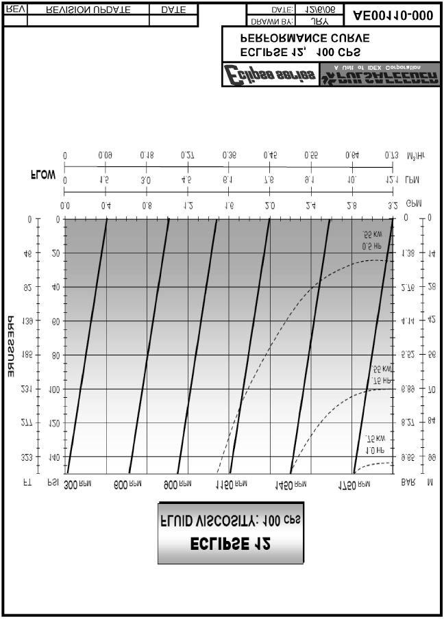
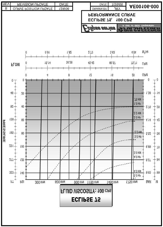
80 21. Performance Curves 74
81 75
82 76
83 77
84 78
85 79
86 80
87 81
88 82
89 83
90 84
91 85
92 86
93 87
94 88
95 89
96 22. ATEX Directive ECO / ISOCHEM / ECLIPSE IOM ADDENDUM ATEX Directive 94/9/EC Potentially Explosive Atmospheres NP IOM REV B 8/10/2005 Scope This addendum is to the Installation, Operation and Maintenance Manual of the ECO, Isochem and Eclipse Gear Pump family of pumps. It includes all the necessary additional information to be considered when installing these pump models in a potentially explosive environments (Group II, Category 2, G & D). Models Included in the Assessment G, GA and GC series ECO Mechanical sealed gear pumps GM and GMC Isochem Magnetically driven gear pumps E Series Eclipse Magnetically driven gear pumps Description of Equipment The general product description for this equipment is positive displacement external gear pumps. They are supplied as mechanically sealed and magnetically driven versions. Intended Usage of the Equipment ECO / Isochem / Eclipse gear pumps are intended to be used to transfer various fluids. With proper sensors or feedback devices they can also be used to meter fluids. Pulsafeeder has decided to construct the pumps to meet the requirements for Group II, category 2 equipment. To meet Category 2 equipment requirements, all possible ignition sources that can occur in normal operation of the pumps and additionally, those that can become effective as a result of malfunctions expected to occur in service must be considered. As the pumps are not intended to meet the requirements of category I, potential ignition sources arising from rare malfunctions can be neglected. Reference Standards 97/38/EC Machinery safety directive EN (2001) Non-electrical equipment for potentially explosive atmospheres - Part 1: Basic method and requirements EN Explosive atmospheres - Explosion prevention and protection - Part I: Basic concepts and methodology EN Degrees of protection provided by enclosures (IP Code) 90
 equipment is suitable for use in Zone 1 areas. In D type Explosive atmosphere (Dust) equipment is suitable for use in Zone 21 areas.")
97 Equipment Equipment in Group II, Category 2, is intended for use in areas in which explosive atmospheres caused by gases, vapors, mists or air/dust mixtures are likely to occur. G & D Atmospheres In G type Explosive atmosphere (Gas, vapor, mist) equipment is suitable for use in Zone 1 areas. In D type Explosive atmosphere (Dust) equipment is suitable for use in Zone 21 areas. Temperature Class Temperature class TX based on ambient and pumped fluid temperature. Different temperature classes can be achieved based on fluid and ambient temperatures (See chart) Temperature Class and Maximum Liquid Temperatures Temperature Class Maximum Surface Temperature C Permitted (Dust) Max. Liquid or Ambient Temperature C Sealed Pumps Magnetic Drive Comments T Fluid temperatures are limited by pump construction T T T T T Normal class rating * Maximum Temperature Class for Eclipse Series Pumps is T6. Technical Support & Service For technical support or service contact: Pulsafeeder Inc Brighton Henrietta Townline Road Rochester, New York USA (585) Protective Earth Ground Symbol 91

98 Sample Tag Additional Equipment Additional equipment such as a Power Monitor, Temperature probe and a Flow meter should be fitted at all times when using a pump in a potentially explosive atmosphere. The pump / unit must also be "Earth Grounded" at all times. A pump should never be "Run Dry" especially in Potentially Explosive Atmospheres. General Usage Precautions 1) The pump must be "Earth Grounded" at all times to prevent Electrostatic charge build up. (When an ATEX approved pump is requested, a "Ground" contact point is provided or identified by the protective earth ground symbol.) The electrical installation must conform to all location relevant codes. 2) The pump must not be used beyond its ratings and if the original operating conditions change, it is the users responsibility to check with Pulsafeeder to confirm if the pump is still acceptable for the new operating conditions. 3) Pulsafeeder will only consider the pump safe for the purpose and duty conditions originally specified by the purchaser. Pulsafeeder will not accept responsibility for pump failure or personal injury arising from misapplication of the product. 4) In the event of any one of the following conditions occurring the pump should be shut down and the cause investigated and rectified. Unaccountable rise in discharge pressure Release of liquid from the pressure relief mechanism Excessive noise emissions Unaccountable rise in operating temperature Excessive power consumption Loss of flow 5) Unauthorized modification or use of components other than original Pulsafeeder spares revokes any liability for consequences, which may result. 6) A pressure relief method must be used at the discharge of the pump to provide over pressure protection. For ATEX Potentially Explosive Atmospheres, a "return to tank type piping system" is recommended to prevent high temperatures due to recycled fluid. continued, next page 92
Installation Operation Maintenance Instruction
 Installation Operation Maintenance Instruction Bulletin #: IOM-NMG-0804 Rev F i ii Pulsafeeder Factory Service Policy Should you experience a problem with your Eclipse Standard/Eclipse Hypo Series pump,
Installation, Operation & Maintenance Manual. Models: E02, E05, E12, E25, E75, E125 ECLIPSE EXTERNAL GEAR METERING PUMP. Bulletin: IOM-ECL-3500-Rev.
 Installation, Operation & Maintenance Manual Models: E02, E05, E12, E25, E75, E125 Bulletin: IOM-ECL-3500-Rev.H ECLIPSE EXTERNAL GEAR METERING PUMP i Pulsafeeder Factory Service Policy Should you experience
Installation, Operation & Maintenance Manual. Models: E02, E05, E12, E25, E75, E125 ECLIPSE EXTERNAL GEAR METERING PUMP. Bulletin: IOM-ECL-3500 Rev I
 Installation, Operation & Maintenance Manual Models: E02, E05, E12, E25, E75, E125 Bulletin: IOM-ECL-3500 Rev I ECLIPSE EXTERNAL GEAR METERING PUMP Pulsafeeder Factory Service Policy Should you experience
Installation Operation Maintenance Instruction Manual
 Model GMC1 Low Flow Magnetically Driven Sealless Gear Pump Installation Operation Maintenance Instruction Manual Bulletin No. GMC1-IOM-02 Rev. 1 Manufactures of Quality Pumps, Controls and Systems ENGINEERED
Service Manual #67. Installation and Service Instructions 6000, 7000 & 8000 Series Magnetically Coupled Pumps
 Service Manual #67 Installation and Service Instructions 6000, 7000 & 8000 Series Magnetically Coupled Pumps Table of Contents Section Description Page 1 General Description 4 2 The Pumping Principle 5
SERIES FE MAGNETIC COUPLED PUMPS
 SERIES FE MAGNETIC COUPLED PUMPS Refer to Bulletin P-518 O-2804 TABLE OF CONTENTS Description Page Number Important Information...3 Chemical Reaction Disclaimer...3 Safety Precautions...3 Installation/Operation
NECO Pumping Systems
 INSTALLATION OPERATION & MAINTENANCE INSTRUCTIONS For Your NECO Pumping Systems Fuel Oil Transfer System THIS COMPLETELY ASSEMBLED, TESTED, PACKAGED SYSTEM IS OF THE HIGHEST QUALITY AND DESIGN. TO OBTAIN
Installation Operation Maintenance ADDENDUM BULLETIN No. PS-IOM-HYP-0203-H
 Installation Operation Maintenance ADDENDUM BULLETIN No. PS-IOM-HYP-0203-H USER NOTE: This addendum serves as additional information for Pulsafeeder PULSAR and PULSAR Shadow metering pumps equipped with
Installation, Operation & Maintenance Supplement Instruction. Bulletin No.: IOMS-PUL PULSA Series 7120V DRIVE MOTOR INSTALLATION
 Installation, Operation & Maintenance Supplement Instruction Bulletin No.: IOMS-PUL-1012 PULSA Series 7120V DRIVE MOTOR INSTALLATION Copyright 2001-2015 Pulsafeeder, Inc. All rights reserved. ii Conventions
LIQUIDYNAMICS Light Viscosity Bulk Transfer Cart
 This manual contains important warnings and information. READ AND KEEP FOR REFERENCE. LIQUIDYNAMICS Light Viscosity Bulk Transfer Cart Instruction & Parts Manual This Manual Covers P/N 33271 P/N 33271
Eclipse. The Power of Design Innovation. Series
 Eclipse The Power of Design Innovation Series Pulsafeeder Technology Since 1936, Pulsafeeder has been recognized as a world leader in fluid handling and control technology. Pulsafeeder continues to deliver
Installation Operation Maintenance ADDENDUM
 Installation Operation Maintenance ADDENDUM Bulletin #: PS-IOM-HYPO2-0111-A FACTORY SERVICE POLICY If you are experiencing a problem with your Pulsafeeder pump, first review the IOM, and consult the troubleshooting
Installation, Operation, & Maintenance Instruction. Bulletin #: IOM-PN-LCM D
 Installation, Operation, & Maintenance Instruction Bulletin #: IOM-PN-LCM-0403- D Manufacturers of Quality Pumps, Controls and Systems ENGINEERED PUMP OPERATIONS 2883 Brighton Henrietta Townline Road Rochester,
KC 5.5, 6, 6H, 7, 8, & 10 SERIES Non-Metallic Centrifugal Pumps Installation and Maintenance Instructions
 KC 5.5, 6, 6H, 7, 8, & 10 SERIES Non-Metallic Centrifugal Pumps Installation and Maintenance Instructions ASSEMBLY Unpack the pump, drive magnet assembly and hardware package from carton and check for
INSTALLATION AND SERVICE INSTRUCTIONS FOR 1008 AND 1010 SERIES PUMPS
 Service Instruction No. 11 INSTALLATION AND SERVICE INSTRUCTIONS FOR 1008 AND 1010 SERIES PUMPS GENERAL DESCRIPTION Pumping Principles Page 2 INSTALLATION Location Page 3 Proper Installation Page 3 Filter
An IDEX Water & Wastewater Business. pulsafeeder.com. Non-Metallic External Gear Pump
 An IDEX Water & Wastewater Business pulsafeeder.com Non-Metallic External Gear Pump Pulsafeeder Expertise Since 1936, Pulsafeeder has been the global leader in fluid handling technology and innovation
Operation & Maintenance Manual for Northern Magnetic Drive Pumps. Operation Manual. Northern Magnetic Drive 4400 and 4600 Series
 Operation Manual Northern Magnetic Drive 4400 and 4600 Series 340 West Benson Avenue Grantsburg, WI 54840 Telephone: 1-800-366-1410 715-463-5177 www.northern-pump.com Page 1 of 16 Table of Contents Cautionary
PROMAG SR SERIES SEAL-LESS CENTRIFUGAL PUMPS
 PROMAG SR SERIES SEAL-LESS CENTRIFUGAL PUMPS INSTALLATION, OPERATION, AND MAINTENANCE INSTRUCTIONS TO OBTAIN THE BEST PERFORMANCE FROM YOUR PROMAG SR PUMP, PLEASE READ THE MANUAL CAREFULLY. Failure to
INSTALLATION, OPERATION AND MAINTENANCE MANUAL (IOM)
") INSTALLATION, OPERATION AND MAINTENANCE MANUAL (IOM) IOM-1088 03-16 Model 1088 Vacu-Gard Blanketing Valve ISO Registered Company SECTION I I. DESCRIPTION AND SCOPE The Model 1088 Vacu-Gard is a tank blanketing
INSTALLATION, OPERATION AND MAINTENANCE MANUAL (IOM) IOM-1088 03-16 Model 1088 Vacu-Gard Blanketing Valve ISO Registered Company SECTION I I. DESCRIPTION AND SCOPE The Model 1088 Vacu-Gard is a tank blanketing
This manual presents installation, servicing, troubleshooting, and maintenance for M PUMPS CM MAG-M SERIES Information that may be required regarding
 Installation, Operating, Maintenance & Safety Instruction for M PUMPS CM MAG-M SERIES Centrifugal light Mag-Drive pumps (CM MAG-M06/1/2/3/4) This manual presents installation, servicing, troubleshooting,
END SUCTION CENTRIFUGAL PUMPS
 OWNERS GUIDE TO INSTALLATION AND OPERATION FW000 009 Supersedes 07 END SUCTION CENTRIFUGAL PUMPS READ THESE INSTRUCTIONS CAREFULLY Read these installation instructions in detail before installing your
SELF PRIMING CHEMICAL SERVICE PUMPS
 SELF PRIMING CHEMICAL SERVICE PUMPS INSTALLATION AND OPERATING INSTRUCTIONS This Manual covers: SELF PRIMING MODEL RANGE J50ECX TO J250ECX STAINLESS STEEL*, and NON METALLIC SEAL PUMP MODEL: SERIAL NO:
Self-Priming Close-Coupled Centrifugal Pumps In 316 Stainless Steel, Bronze and Cast Iron
 Please read and save this Repair Parts Manual. Read this manual and the General Operating Instructions carefully before attempting to assemble, install, operate or maintain the product described. Protect
Installation, Operation, & Maintenance Instruction. Model DC7. Bulletin #: IOM-DC C
 Installation, Operation, & Maintenance Instruction Model DC7 Bulletin #: IOM-DC7-0407- C Manufacturers of Quality Pumps, Controls, and Systems STANDARD PUMP OPERATIONS 27101 Airport Road Punta Gorda, FL
SHURflo Self-Priming Close-Coupled Centrifugal Pumps In 316 Stainless Steel, Bronze and Cast Iron
 Please read and save this Repair Parts Manual. Read this manual and the General Operating Instructions carefully before attempting to assemble, install, operate or maintain the product described. Protect
1/2" AIR DRIVEN DIAPHRAGM PUMP
 1/2" DRIVEN DIAPHRAGM PUMP OPERATION AND SERVICE GUIDE O-1225D NOV. 2008 Page 1 of 6 Refer to Bulletin P-605, Parts List P-9151 DRIVEN, DOUBLE DIAPHRAGM PUMP MANUAL Congratulations on purchasing one of
SERIES PC INSTRUCTION AND OPERATION MANUAL
 MEGGA SERIES PC INSTRUCTION AND OPERATION MANUAL Models PCT and PCF Close-coupled and frame-mounted single-stage horizontal end-suction pumps. WARNING: Read this manual before installing or operating this
Installation & Operating Manual
 Installation & Operating Manual 25IPCC-M 7/08 Edition PC Series C E N T R I F U G A L Congratulations On Your Choice In Purchasing This Webtrol Pump Its Quality is unsurpassed in material and workmanship
Operating Manual for Rotary Gear Pumps CMI, S.A. (Mendaro, Guipuzkoa, Spain)
") Operating Manual for Rotary Gear Pumps CMI, S.A. (Mendaro, Guipuzkoa, Spain) Pre-Installation 1. Choose a location that is easily accessible for pump servicing. Ensure adequate electrical service is available.
Operating Manual for Rotary Gear Pumps CMI, S.A. (Mendaro, Guipuzkoa, Spain) Pre-Installation 1. Choose a location that is easily accessible for pump servicing. Ensure adequate electrical service is available.
Service Manual #40. Installation and Service Instructions 4000 Series Pumps
 Installation and Service Instructions 4000 Series Pumps General Description 4100/4120 Models Tuthill's 4100 and 4120 pumps are available in five sizes each, with nominal capacities ranging from 0.5 to
INSTALLATION, OPERATION AND MAINTENANCE INSTRUCTIONS
 INSTALLATION, OPERATION AND MAINTENANCE INSTRUCTIONS Contents Section 1. General Observations... 2 2. Operation... 4 3. Control During Operation... 5 4. Trouble Shooting... 6 5. Maintenance... 7 Please
OPERATION MANUAL NT50 NOMAD TRANS-FLO AIR-OPERATED DOUBLE DIAPHRAGM PUMPS. A JDA Global Company. 7/11 rev. 1
 OPERATION MANUAL NT50 NOMAD TRANS-FLO AIR-OPERATED DOUBLE DIAPHRAGM PUMPS A JDA Global Company 7/11 rev. 1 CAUTION SAFETY POINTS TEMPERATURE LIMITS: Neoprene -17.8 C to 93.3 C 0 F to 200 F Buna-N -12.2
Model DF233 Control Valve
 Figure 1 DF233 Control Valve TABLE OF CONTENTS Introduction 2 Body and Packing Reassembly 7 Specifications 3 Fail Closed Actuator Reassembly 8 Valve Sizes 3 Fail Open Actuator Reassembly 9 Unpacking 4
SERVICE MANUAL 200 SERIES MOTORIZED 20352, 20452, 20551, 20552, AND MODELS
 Section: MOYNO 500 PUMPS Page:1 of 4 Date: March 1, 1998 SERVICE MANUAL MOYNO 500 PUMPS 200 SERIES MOTORIZED 20352, 20452, 20551, 20552, 22051 AND 22052 MODELS DESIGN FEATURES Housing: AISI 316 stainless
Installation, Operation & Maintenance Manual
 Original Instructions if03 Installation, Operation & Maintenance Manual Magnetic Drive Coro-Flo Pump Models MDC0 and MDC2 Model MDC0 Warning: () Periodic inspection and maintenance of Corken products is
OPERATION MANUAL. ALUMINUM Models DUCTILE Models 316 S.S. Models AIR-OPERATED DOUBLE DIAPHRAGM PUMPS
 OPERATION MANUAL 3 METALLIC PUMP (CLAMPED) PWR-FLO TM AIR DISTRIBUTION SYSTEM NPF80 AIR-OPERATED DOUBLE DIAPHRAGM PUMPS ALUMINUM Models DUCTILE Models 316 S.S. Models A JDA Global Company CAUTIONS - READ
Model DF269 Control Valve
 Figure 1 DF269 Control Valve TABLE OF CONTENTS Introduction 2 Fail Open Actuator Disassembly 6 General 2 Body and Packing Reassembly 7 Scope 2 Fail Closed Actuator Resassembly 8 Specifications 3 Fail Open
WMTA6 LN SERIES SEAL-LESS MAG-DRIVE MULTI-STAGE TURBINE PUMPS
 WMTA6 LN SERIES SEAL-LESS MAG-DRIVE MULTI-STAGE TURBINE PUMPS INSTALLATION, OPERATION, AND MAINTENANCE INSTRUCTIONS TO OBTAIN THE BEST PERFORMANCE FROM YOUR WARRENDER WMTA6 LN PUMP, PLEASE READ THIS MANUAL
Installation, Operation & Maintenance Instruction. Models: FMP Series 30, 40, 50. PeriFlo FMP PERISTALTIC PUMP. Bulletin #: IOM-PFL-4502
 Installation, Operation & Maintenance Instruction Models: FMP Series 30, 40, 50 Bulletin #: IOM-PFL-4502 PeriFlo FMP PERISTALTIC PUMP Pulsafeeder Factory Service Policy Should you experience a problem
Installation and Service Instructions 1008 & 1010 Size Pumps
 Installation and Service Instructions 1008 & 1010 Size Pumps Excellence at work. Excellence in life. Table of Contents The Pumping Principle 3 Location 3 Proper Installation 3 Filter Protection 4 Startup
VKC5.5,6,6H, 7,8,10 SERIES Sealless Non-Metallic Vertical Pumps Installation and Maintenance Instructions. Pat.No. 5,708,313
 ASSEMBLY WARNING: Magnetic field hazard. This pump contains powerful rare earth magnets. When the pump is disassembled (not connected to a motor) and the magnets are exposed, these magnets produce powerful
PRODUCT SERVICE MANUAL FOR BK12DHZ PUMPS
 PRODUCT SERVICE MANUAL FOR BK12DHZ PUMPS WARNING This manual, and the GENERAL INSTRUCTION MANUAL SRM00046, should be read thoroughly prior to pump installation, operation or maintenance. Manual No. SRM00095
Installation, Operation, and Maintenance Manual Outdoor Glycol Feed System JWOP /055/100
 Installation, Operation, and Maintenance Manual Outdoor Glycol Feed System JWOP-53-030/055/100 Rev. 1 3/21/11 K.G. Type - John Wood #JWOP-53-030/055/100, Outdoor Glycol Feed System Capacity 30/55/100 Gallons
Installation and Service Instructions. ST Series Pumps
 Installation and Service Instructions ST Series Pumps! WARNING READ MANUAL before operating or working on a Tuthill ST Series pump. Page 2 of 24 4/24/03 Table of Contents Page 4 Page 5 Page 5 Page 6 Page
Installation, Operation & Maintenance Manual. Models: ChemTuff Series PeriFlo ChemTuff PERISTALTIC PUMP. IOM-PFL-4600-Rev.B
 Installation, Operation & Maintenance Manual Models: ChemTuff Series 10 22 IOM-PFL-4600-Rev.B PeriFlo ChemTuff PERISTALTIC PUMP Pulsafeeder Factory Service Policy Should you experience a problem with your
OPERATION MANUAL AIR-OPERATED DOUBLE DIAPHRAGM PUMPS 3 POLYPROPYLENE PUMP PWR-FLO TM AIR DISTRIBUTION SYSTEM NPF 80. A JDA Global Company
 OPERATION MANUAL 3 POLYPROPYLENE PUMP PWR-FLO TM AIR DISTRIBUTION SYSTEM NPF 80 AIR-OPERATED DOUBLE DIAPHRAGM PUMPS A JDA Global Company CAUTIONS - READ FIRST CAUTION: Do not apply compressed air to the
OPERATION MANUAL AIR-OPERATED DOUBLE DIAPHRAGM PUMPS 2 POLYPROPYLENE PUMP PWR-FLO TM AIR DISTRIBUTION SYSTEM NPF 50 BOLTED. A JDA Global Company
 OPERATION MANUAL 2 POLYPROPYLENE PUMP PWR-FLO TM AIR DISTRIBUTION SYSTEM NPF 50 BOLTED AIR-OPERATED DOUBLE DIAPHRAGM PUMPS A JDA Global Company CAUTIONS - READ FIRST CAUTION: Do not apply compressed air
 INSTRUCTIONS Your Ampco centrifugal pump is a rugged unit designed to provide years of low cost pumping service. There is a small amount of necessary care required to ensure you of this expected long service.
INSTRUCTION MANUAL MODEL 213, 214, 215 and 216 POSITIVE DISPLACEMENT FLOWMETERS
 INSTRUCTION MANUAL MODEL 213, 214, 215 and 216 POSITIVE DISPLACEMENT FLOWMETERS TABLE OF CONTENTS Do s and Don ts.................................. Pg 2 General Description...............................
INSTRUCTION MANUAL INTERNAL GEAR PUMP TITAN G-4124A SERIES=> FLANGED TITAN G-124A SERIES => FLANGED MODELS:
 INSTRUCTION MANUAL INTERNAL GEAR PUMP TITAN G-4124A SERIES=> FLANGED TITAN G-124A SERIES => FLANGED MODELS: G-H, G-HL, G-K, G-KK, G-L, G-LQ, G-LL, GLS, G-Q, G-QS 1 Contents Maintenance Thrust bearing adjustment
Keystone Butterfly valves ParaSeal Installation and maintenance instructions
 Before installation these instructions must be fully read and understood Please read these instructions carefully Hazard potentials: disregarding of instructions improper use of product insufficiently
PRODUCT SERVICE MANUAL. BK6DHZ(C)-250, 275, 312 and 400 PUMPS
-250, 275, 312 and 400 PUMPS") PRODUCT SERVICE MANUAL BK6DHZ(C)-250, 275, 312 and 400 PUMPS WARNING This manual, and the GENERAL INSTRUCTION MANUAL, SRM00046, should be read thoroughly prior to pump installation, operation or maintenance.
PRODUCT SERVICE MANUAL BK6DHZ(C)-250, 275, 312 and 400 PUMPS WARNING This manual, and the GENERAL INSTRUCTION MANUAL, SRM00046, should be read thoroughly prior to pump installation, operation or maintenance.
Installation, Operation and Maintenance Manual
 Installation, Operation and Maintenance Manual Manual Polymer Makedown Systems Manufacturers of Quality Pumps, Controls, and Systems Standard Product Operations 27101 Airport Rd., Punta Gorda, FL 33982
UV PROCESS SUPPLY, INC. CON-TROL-CURE ½ DIAPHRAGM PUMP INSTRUCTION MANUAL PART # J
 1 IMPORTANT: READ THIS MANUAL CAREFULLY BEFORE INSTALLING, OPERATING OR SERVICING. PUMP DATA TYPE: MAT'L: WEIGHT: Air Operated Double Diaphragm Polypropylene or PVDF or Acetal PVDF (Polyvinylidene Fluoride)
300 SERIES 331, 332, 333, 344, 356 AND 367 MODELS
 Section: MOYNO 500 PUMPS Page: 1 of 8 Date: March 1, 1998 SERVICE MANUAL MOYNO 500 PUMPS 300 SERIES 331, 332, 333, 344, 356 AND 367 MODELS Mechanical Seal Models Packing Gland Models MODELS DESIGN FEATURES
Installation and Service Instructions 1018, 1020, 1022, & 1024 Size Pumps
 Installation and Service Instructions 1018, 1020, 1022, & 1024 Size Pumps Excellence at work. Excellence in life. Table of Contents General Description 3 The Pumping Principle 3 Location 3 Proper Installation
OPERATION MANUAL. ALUMINUM Models. 316 S.S. Models NTG25 NOMAD TRANS-FLO AIR-OPERATED DOUBLE DIAPHRAGM PUMPS. A JDA Global Company. 1/14 rev.
 OPERATION MANUAL NTG25 NOMAD TRANS-FLO AIR-OPERATED DOUBLE DIAPHRAGM PUMPS ALUMINUM Models 316 S.S. Models A JDA Global Company 1/14 rev. 3 CAUTION SAFETY POINTS TEMPERATURE LIMITS: Neoprene -17.8 C to
NECO Pumping Systems
 INSTALLATION OPERATION & MAINTENANCE INSTRUCTIONS For Your NECO Pumping Systems PACKAGED CIRCULATING SYSTEM THIS COMPLETELY ASSEMBLED, TESTED, PACKAGED CIRCULATING SYSTEM IS OF THE HIGHEST QUALITY AND
DeZURIK " BAW AWWA BUTTERFLY VALVES WITH EPOXY-RETAINED SEAT
 DeZURIK 20 144" BAW AWWA BUTTERFLY VALVES WITH EPOXY-RETAINED SEAT Instruction D10373 April 2017 Instructions These instructions provide information about the 20 (250 F2 model only) and the 24-144 BAW
KP-C Series. Close Coupled End Suction Centrifugal Pumps. Installation, Operation and Maintenance
 KP-C Series Close Coupled End Suction Centrifugal Pumps Installation, Operation and Maintenance PUMP MODEL NOMENCLATURE KP - 8 x 6 x 16 - E C - AI - BCM Pump Series Suction Pipe Size (in) Discharge Pipe
INSTRUCTION MANUAL AND PARTS LIST FOR PG/RG3D_-187, 218, 250 and 312 SERIES PUMPS
 INSTRUCTION MANUAL AND PARTS LIST FOR PG/RG3D_-187, 218, 250 and 312 SERIES PUMPS WARNING This Instruction Manual and General Instructions Manual, CA-1, should be read thoroughly prior to pump installation,
OPERATOR S MANUAL A
 OPERATOR S MANUAL 670144-A INCLUDING: OPERATION, INSTALLATION & MAINTENANCE RELEASED: 12-18-15 1/4" DIAPHRAGM PUMP 1:1 RATIO (NON-METALLIC) (REV: A) 67 0144-A READ THIS MANUAL CAREFULLY BEFORE INSTALLING,
Installation, Operation & Maintenance Manual. Models: GLM7 PULSA GLM MECHANICAL DIAPHRAGM METERING PUMP. Bulletin: IOM-GLM-5001-Rev.
 Installation, Operation & Maintenance Manual Models: GLM7 Bulletin: IOM-GLM-5001-Rev.B PULSA GLM MECHANICAL DIAPHRAGM METERING PUMP Pulsafeeder Factory Service Policy Should you experience a problem with
INSTALLATION, OPERATION AND MAINTENANCE INSTRUCTIONS
 Setting Innovative Standards M PUMPS SRL Via dell artigianato, 120 45015 Corbola (RO) Italia Tel. +39 0426 346304 Fax + 39 0426 349126 1 info@mpumps.it MAGNETIC DRIVE PUMPS Centrifugal, peripheral, mag-drive
OPERATION MANUAL. DUCTILE Models NT100 NOMAD TRANS-FLO AIR-OPERATED DOUBLE DIAPHRAGM PUMPS. A JDA Global Company. 5/13 rev.2
 OPERATION MANUAL NT100 NOMAD TRANS-FLO AIR-OPERATED DOUBLE DIAPHRAGM PUMPS DUCTILE Models A JDA Global Company 5/13 rev.2 CAUTION SAFETY POINTS TEMPERATURE LIMITS: Neoprene -17.8 C to 93.3 C 0 F to 200
4 - Way Control 4 - Way Control 4 - Way Control with lock
 INSTALLATION / OPERATION / MAINTENANCE 1. DESCRIPTION MODEL 0-02 (Full Internal Port) Powertrol Valve This manual contains information for installation, operation and maintenance of the Cla-Val Co. 0-02
Routine Compressor Maintenance
 Establishing a regular, well-organized maintenance program and strictly following it is critical to maintaining the performance of a compressed air system. One person should be given the responsibility
SAFETY MANUAL READ FIRST!
 966-05-XX SAFETY MANUAL READ FIRST! IMPORTANT: READ THESE WARNINGS AND SAFETY PRECAUTIONS PRIOR TO INSTALLATION OR OPER- ATION. FAILURE TO COMPLY WITH THESE INSTRUC- TIONS COULD RESULT IN PERSONAL INJURY
BLACKMER BYPASS VALVES
 BLACKMER BYPASS VALVES INSTALLATION OPERATION AND MAINTENANCE INSTRUCTIONS EBSRAY MODEL: RV18 RV18CBS2, RV18CBS3, RV18VRS10, RV18VRS14, RV18VRS19 967020 INSTRUCTIONS NO. 551-E00 Section Effective Replaces
Series Base mounted pump. Installation and operating instructions
 Series 4030 Installation and File No: 40.80 Date: june 25, 2015 Supersedes: 40.80 Date: october 10, 2009 contents General 4 Inspection 4 Installation - Series 4030 base mounted Pump 4 1.0 Location 4 2.0
EN. 850 Filtrate Pumps. Technical Specification Pages
 850 17.01.EN 850 Filtrate Pumps Technical Specification Pages 850 Series Filtrate Pump 850 17.01.EN This page left intentionally blank. 1.0 Overview. The 850 is Carver s filtrate pump line designed for
Crispin Valves Operating Guide. Crispin
 Crispin Valves Operating Guide Crispin Since 1905 Crispin Multiplex Manufacturing Co. 600 Fowler Avenue Berwick, PA 18603 1-800-AIR-VALV T: (570) 752-4524 F: (570) 752-4962 www.crispinvalve.com sales@crispinvalve.com
VIKING HG SERIES HELICAL GEAR EXTERNAL GEAR PUMPS
 Page 350.1 Series Description Viking s HG series positive displacement pumps are designed to provide low noise transfer and processing of clean, lubricating liquids for applications such as lube oils,
Installation and Service Instructions 1012, 1014, 1015, & 1017 Size Pumps
 Installation and Service Instructions 1012, 1014, 1015, & 1017 Size Pumps Excellence at work. Excellence in life. Table of Contents General Description 3 The Pumping Principle 3 Location 3 Proper Installation
300 SERIES 30100, 30102, 30104, AND MODELS
 Section: MOYNO 500 PUMPS Page: 1 of 4 Date: March 1, 1998 SERVICE MANUAL MOYNO 500 PUMPS 300 SERIES 30100, 30102, 30104, AND 30105 MODELS DESIGN FEATURES Housing: Phenolic Pump Rotor: Phenolic Elastomers:
Model 990 & 990V INSTALLATIONS AND OPERATING INSTRUCTIONS
 Model 990 & 990V Advanced Marine Technologies, Inc. 212 Yacht Club Drive Saint Augustine FL 32084 866-922-4804 904-829-1800 FAX 904-829-2800 pumps@x-change-r.com www.x-change-r.com INSTALLATIONS AND OPERATING
Operation & Maintenance Manual For 4900 Series Pumps Bulletin 134
 For 340 West Benson Avenue Grantsburg, WI 54840 1-800-366-1410 715-463-5177 www.northern-pump.com Table of Contents Introduction... 3 Cautionary Statements... 5 Pump Installation... 6 Removal from Installation...
VERTICAL MULTI-STAGES CENTRIFUGAL PUMPS
 Installation and Operating Instructions VERTICAL MULTI-STAGES CENTRIFUGAL PUMPS Models 1, 3, 5, 10, 15, 20, 32, 45, 64, 90, 120, 150 1. Model numbering and nameplate format 1.1 Model numbering Example:
VERTICAL MULTI-STAGE CENTRIFUGAL PUMPS
 Installation and Operating Instructions VERTICAL MULTI-STAGE CENTRIFUGAL PUMPS Models 1, 3, 5, 10, 15, 20, 32, 45, 64, 90 1. Model numbering and nameplate format 1.1 Model numbering Example: SBI / SBN
OPERATION MANUAL NT80 NOMAD TRANS-FLO AIR-OPERATED DOUBLE DIAPHRAGM PUMPS. A JDA Global Company. 5/13 rev.2
 OPERATION MANUAL AIR-OPERATED DOUBLE DIAPHRAGM PUMPS A JDA Global Company 5/13 rev.2 CAUTION SAFETY POINTS TEMPERATURE LIMITS: Neoprene -17.8 C to 93.3 C 0 F to 200 F Buna-N -12.2 C to 82.2 C 10 F to 180
Model and Series 115 VAC INDUSTRIAL DIAPHRAGM PUMPS. PumpAgents.com - buy pumps and parts online INDUSTRIAL DIAPHRAGM PUMPS
 Model 31801 and 31800 Series 115 VAC INDUSTRIAL DIAPHRAGM PUMPS INDUSTRIAL DIAPHRAGM PUMPS FEATURES Run Dry Ability Self-Priming Thermal Overload Protected Motor Easy Installation Low Amp Draw Compact
Northern Pump A Division of McNally Industries, LLC
 Operation & Maintenance Manual for Northern 4900 Injection Operation & Maintenance Manual For Northern 4900 Injection Northern Pump A Division of McNally Industries, LLC 340 West Benson Avenue Grantsburg,
Vickers. Overhaul Manual. Vane Pumps. Small and Large Series Combination Pumps VC(K)(S)-**-(*)*D*-6(1) VC(K)(S)-**-(*)-*-*D*-5(1)
(S)-**-(*)*D*-6(1) VC(K)(S)-**-(*)-*-*D*-5(1)") Overhaul Manual Vickers Vane Pumps Small and Large Series Combination Pumps VC(K)(S)-**-(*)*D*-6(1) VC(K)(S)-**-(*)-*-*D*-5(1) Revised 12/1/86 I-3150-S Table of Contents Section I. Introduction................................................................................
Overhaul Manual Vickers Vane Pumps Small and Large Series Combination Pumps VC(K)(S)-**-(*)*D*-6(1) VC(K)(S)-**-(*)-*-*D*-5(1) Revised 12/1/86 I-3150-S Table of Contents Section I. Introduction................................................................................
OPERATION MANUAL. ALUMINUM Models. 316 S.S. Models NTG40 NOMAD TRANS-FLO AIR-OPERATED DOUBLE DIAPHRAGM PUMPS. A JDA Global Company. 1/14, Rev.
 OPERATION MANUAL NTG40 NOMAD TRANS-FLO AIR-OPERATED DOUBLE DIAPHRAGM PUMPS ALUMINUM Models 316 S.S. Models A JDA Global Company 1/14, Rev. 3 CAUTION SAFETY POINTS TEMPERATURE LIMITS: Neoprene -17.8 C to
KEYSTONE SERIES 320 BUTTERFLY VALVES INSTALLATION AND MAINTENANCE INSTRUCTIONS
 Before installation these instructions must be fully read and understood HAZARD POTENTIALS disregarding of instructions improper use of product insufficiently qualified personnel Valve application to be
4.2 WATER PUMP (GEAR CASE MOUNTED AND LATER) (GCM)
 (GCM)") SERIES 60 SERVICE MANUAL 4.2 WATER PUMP (GEAR CASE MOUNTED - 1991 AND LATER) (GCM) The centrifugal-type water pump circulates the engine coolant through the cooling system. The pump is mounted on the rear
SERIES 60 SERVICE MANUAL 4.2 WATER PUMP (GEAR CASE MOUNTED - 1991 AND LATER) (GCM) The centrifugal-type water pump circulates the engine coolant through the cooling system. The pump is mounted on the rear
F-4600 INLINE ULTRASONIC FLOW METER Installation and Operation Guide
 F-4600 INLINE ULTRASONIC FLOW METER Installation and Operation Guide 11451 Belcher Road South, Largo, FL 33773 USA Tel +1 (727) 447-6140 Fax +1 (727) 442-5699 1054-7 / 34405 www.onicon.com sales@onicon.com
Maintenance Instructions
 General Note These instructions contain information common to more than one model of Bevel Gear Drive. To simplify reading, similar models have been grouped as follows: GROUP 1 Models 11, 0, 1,, (illustrated),,
INSTRUCTION MANUAL AND PARTS LIST FOR 3SIC AND 4SIC SERIES PUMPS
 TM INSTRUCTION MANUAL AND PARTS LIST FOR 3SIC AND 4SIC SERIES PUMPS WARNING This manual, and General Instructions Manual, CA-1 should be read thoroughly prior to pump installation, operation or maintenance.
End Suction Centrifugal
 M o d e l s 3 U / 3 U B End Suction Centrifugal Operating Instructions, Installation & Maintenance Manual Certified to NSF/ANSI 6, ANNEX G * NSF/ANSI 6 Annex G listed models: 3U EBARA International Corporation
Operation & Maintenance Manual 4900 Series Pipeline Injection Pumps Bulletin 150
 340 West Benson Avenue Grantsburg, WI 54840 1-800-366-1410 715-463-5177 www.northern-pump.com Table of Contents Introduction... 3 Rotation... 4 Hydraulic Balance... 5 Cautionary Statements... 6 Pump Installation...
SHURflo Pedestal-Mount Centrifugal Pumps
 316 Stainless Steel, Bronze and Cast Iron Models Please read and save this Repair Parts Manual. Read this manual and the General Operating Instructions carefully before attempting to assemble, install,
KEYSTONE OPTISEAL F14/16-15/17 AND BREWSEAL BUTTERFLY VALVES INSTALLATION AND MAINTENANCE INSTRUCTIONS
 Before installation these instructions must be fully read and understood 4. Ozone: storage rooms should not contain any equipment generating ozone. E.g. lamps, electric motors. IMPORTANT Before valves
Non-Metallic External Gear Pump
 An IDEX Water & Wastewater Business pulsafeeder.com Non-Metallic External Gear Pump Pulsafeeder Expertise Since 1936, Pulsafeeder has been the global leader in fluid handling technology and innovation
END SUCTION CENTRIFUGAL PUMPS
 OWNERS GUIDE TO INSTALLATION AND OPERATION END SUCTION CENTRIFUGAL PUMPS FW000 0 Supersedes 009 READ THESE INSTRUCTIONS CAREFULLY Read these installation instructions in detail before installing your pump.
I & M Mark 78 Series. Ideal Installation. Start-Up. Installation & Maintenance Instructions for Mark 78 Control Valves (1-1/2-2 )
") I & M Mark 8 Series 0 Wasson Road Cincinnati, OH 4509 USA Phone 5-5-5600 Fax 5-8-005 info@richardsind.com www.jordanvalve.com Installation & Maintenance Instructions for Mark 8 Control Valves (-/ - ) Warning:
I & M Mark 8 Series 0 Wasson Road Cincinnati, OH 4509 USA Phone 5-5-5600 Fax 5-8-005 info@richardsind.com www.jordanvalve.com Installation & Maintenance Instructions for Mark 8 Control Valves (-/ - ) Warning:
Vane Pumps. Single Stage Single and Double Vane Pumps. Vickers. Overhaul Manual
 Vickers Vane Pumps Overhaul Manual Single Stage Single and Double Vane Pumps V14, 124, 134,144 V19, 129, 139, 149 V15, 125, 135, 145 V35*, 36*, 45*, 46* V18, 128, 138, 148 (V)VF-**-**, (V)VG-**-** Reprinted
OPERATION MANUAL.25 METALLIC PUMP PWR-FLO TM AIR DISTRIBUTION SYSTEM
 OPERATION MANUAL.25 METALLIC PUMP PWR-FLO TM AIR DISTRIBUTION SYSTEM CAUTIONS - READ FIRST CAUTION: Do not apply compressed air to the exhaust port pump will not function. CAUTION: Do not exceed 79 C (174
Table 6-1. Problems and solutions with pump operations. No Fluid Delivery
 Table 6-1. and solutions with pump operations No Fluid Delivery Fluid level in the reservoir is low. Oil intake pipe or inlet filter is plugged. Air leak in the inlet line prevents priming or causes noise
WARNING CAUTION. CAUTION Do not exceed 120 psig (8.3 bar) air-inlet pressure.
 air-inlet pressure.") 13966-300-BM SAFETY MANUAL READ FIRST! IMPORTANT: READ THESE WARNINGS AND SAFETY PRECAUTIONS PRIOR TO INSTALLATION OR OPER- ATION. FAILURE TO COMPLY WITH THESE INSTRUC- TIONS COULD RESULT IN PERSONAL INJURY
13966-300-BM SAFETY MANUAL READ FIRST! IMPORTANT: READ THESE WARNINGS AND SAFETY PRECAUTIONS PRIOR TO INSTALLATION OR OPER- ATION. FAILURE TO COMPLY WITH THESE INSTRUC- TIONS COULD RESULT IN PERSONAL INJURY