Installation, Operation, & Maintenance Instruction. Bulletin #: IOM-PN-LCM D
|
|
|
- Grace Hunter
- 5 years ago
- Views:
Transcription

 292-8000 Fax (585)")
1 Installation, Operation, & Maintenance Instruction Bulletin #: IOM-PN-LCM D Manufacturers of Quality Pumps, Controls and Systems ENGINEERED PUMP OPERATIONS 2883 Brighton Henrietta Townline Road Rochester, New York, Telephone (585) Fax (585) www,pulsa.com
2 Pulsafeeder Factory Service Policy Should you experience a problem with your Pulsafeeder pump, first consult the troubleshooting guide in your operation and maintenance manual. If the problem is not covered or cannot be solved, please contact your local Pulsafeeder Sales Representative, or our Technical Services Department for further assistance. Trained technicians are available to diagnose your problem and arrange a solution. Solutions may include purchase of replacement parts or returning the unit to the factory for inspection and repair. All returns require a Return Authorization number to be issued by Pulsafeeder. Parts purchased to correct a warranty issue may be credited after an examination of original parts by Pulsafeeder. Warranty parts returned as defective which test good will be sent back freight collect. No credit will be issued on any replacement electronic parts. Any modifications or out-of-warranty repairs will be subject to bench fees and costs associated with replacement parts. Safety Considerations: 1. Read and understand all related instructions and documentation before attempting to install or maintain this equipment 2. Observe all special instructions, notes, and cautions. 3. Act with care and exercise good common sense and judgment during all installation, adjustment, and maintenance procedures. 4. Ensure that all safety and work procedures and standards that are applicable to your company and facility are followed during the installation, maintenance, and operation of this equipment. Copyright 2004 Pulsafeeder, Inc. All rights reserved. Information in this document is subject to change without notice. No part of this publication may be reproduced, stored in a retrieval system or transmitted in any form or any means electronic or mechanical, including photocopying and recording for any purpose other than the purchaser s personal use without the written permission of Pulsafeeder, Inc. ii
3 Table of Contents 1. INTRODUCTION PRINCIPLES OF OPERATION Overall Operation Reagent Head Assembly Control Assembly Gear Ratio Assembly EQUIPMENT INSPECTION STORAGE Short Term Long Term INSTALLATION Location Piping System Suction Pressure Requirements Discharge Pressure Requirements EQUIPMENT STARTUP Fastener Inspection Output Adjustment Priming the Reagent Head Calibration MAINTENANCE Lubrication Wet End Removal, Inspection, & Reinstallation Diaphragm Removal & Reinstallation Check Valves General Description Check Valve Removal & Reinstallation Motor Removal & Reinstallation Gearset Removal Gearset Replacement REPLACEMENT PARTS KOPkit Program Ordering KOPkits or Parts TROUBLESHOOTING PIPING ACCESSORIES DIMENSIONAL DRAWINGS PARTS DIAGRAMS AND PARTS LISTS MAINTENANCE LOG...25 iii
4 iv

5 1. Introduction PULSAtron Series M metering pumps are positive displacement reciprocating pumps. Each pump consists of a power end and a process end separated by a mechanically operated diaphragm. Individual pumps will vary in appearance due to various liquid ends and accessories, however, the basic principles of operation remain the same. 2. Principles Of Operation 2.1 Overall Operation Figure 1 A diaphragm reciprocates at a preset stroke length, displacing an exact volume of process fluid. Diaphragm retraction causes the product to enter through the suction check valve. Diaphragm advance causes the discharge of an equal amount of the product through the discharge check valve. 2.2 Reagent Head Assembly The typical reagent head assembly consists of reagent head, diaphragm, and suction and discharge cartridge check valves. This assembly is the only part of the pump to contact the process liquid; consequently, maintenance is critical to pump performance. 2.3 Control Assembly PULSAtron Series M pumps incorporate a lost motion style of stroke length adjustment to limit diaphragm travel during the suction portion of each stroke. The stroke length setting is indicated by a (0% 100%) scale located on the stroke adjustment assembly. Stroke length is changed by loosening the locking screw and turning the hand knob. This turns a mechanism which limits rearward travel of the diaphragm. 2.4 Gear Ratio Assembly PULSAtron Series M pumps are driven by an electric motor mounted on the motor adaptor input flange. The motor drives a set of worm gears that convert rotational speed into torque. They, in turn, power the eccentric shaft assembly that converts rotary motion into reciprocating motion. 1
6 3. Equipment Inspection Check all equipment for completeness against the order and for any evidence of shipping damage. Shortages or damage must be reported immediately to the carrier and your authorized representative or distributor of PULSAtron Series M pumps. 4. Storage Short Term Storage of PULSAtron Series M pumps for up to 12 months is considered short-term. The recommended short-term storage procedures are: a) Store the pump indoors at room temperature in a dry environment. b) If required by the operating environment, take precautions to prevent entry of water or humid air into the eccentric enclosure. c) Prior to startup, perform a complete inspection and then start up in accordance with instructions in this manual Long Term Every twelve months, in addition to the above short-term procedures, power up the motor and operate the pump for a minimum of one hour. It is not necessary to have liquid in the reagent head during this operation, but the suction and discharge ports must be open to atmosphere. After twelve months of storage, Pulsafeeder s warranty cannot cover such items which are subject to deterioration with age such as seals, gaskets, and diaphragms. If the pump has been in storage longer than 12 months it is recommended that such items be inspected and replaced as necessary prior to startup. Materials and labor to replace this class of item under this circumstance are the purchaser s responsibility. For a continuance of the initial warranty after extended storage, equipment inspection and any required refurbishing must be done by a Pulsafeeder representative. 5. Installation 5.1 Location When selecting an installation site or designing a chemical feed package system, consideration should be given to access for routine maintenance. PULSAtron Series M pumps are designed to operate indoors and outdoors, but it is desirable to provide a hood or covering for outdoor service. External heating is required if ambient temperatures below 0 C (32 F) are anticipated. Check with the factory if concerned with the suitability of the operating environment. The pump must be rigidly bolted to a solid and flat foundation to minimize vibration, which can loosen connections. When the pump is bolted down, care must be taken to avoid distorting the base and affecting alignments. The pump must be level within 5. This will assure that the check valves can operate properly. 2
7 5.2 Piping System All piping systems should include: 1. A separate system relief valve to protect piping and process equipment, including the pump, from excess process pressures. An external relief valve is required! 2. Shutoff valves and unions (or flanges) on suction and discharge piping. This permits check valve inspection without draining long runs of piping. Shutoff valves should be of the same size as connecting pipe. Ball valves are preferred since they offer minimum flow restriction. 3. An inlet strainer, if appropriate for the product being pumped. Pump check valves are susceptible to dirt and other solid contaminants, and any accumulation can cause malfunction. The strainer should be located between the suction shutoff valve and the pump suction valve. It must be sized to accommodate the flow rate and the anticipated level of contamination. A 100 mesh screen size is generally recommended. 4. Vacuum/pressure gauges in the suction and discharge lines in order to check system operation. Gauges should be fitted with protective shutoff valves for isolation while not in use. Piping weight must not be supported by valve housings or other portions of the reagent head, as the resulting stresses can cause leaks. If appropriate, provide for thermal expansion and contraction so that no excess force or moments are applied to the pump. When making process connections, ensure that the check valve assemblies do not rotate as the threaded connections are secured. It is critical, especially with plastic construction, that the check valves not be too tight into the reagent head. In piping assembly, use a sealing compound chemically compatible with the process material. Users of sealing tape are cautioned to ensure that the entering pipe thread ends are not taped, and that tape is removed from previously-used threads to the maximum practical extent prior to re-use. Both new and existing piping should be cleaned, preferably by flushing with a clean liquid (compatible with process material) and blown out with air, prior to connection to the pump. 5.3 Suction Pressure Requirements Although PULSAtron Series M metering pumps have some suction lift capability, a flooded suction (i.e., suction pressure higher than atmospheric pressure) is preferable whenever possible. The pump should be located as close as possible to the suction side reservoir or fluid supply source. For fluid with a vapor pressure of 5 psia or less (at operating temperature) the wet suction lift capability is approximately ten (10) feet. If this requirement is not met, the pump will not provide reliable, accurate flow. In suction lift conditions, the use of a foot valve is recommended at the lowest point of the pickup tube or pipe. Pumps under suction lift conditions may require some liquid priming before they will operate reliably. 5.4 Discharge Pressure Requirements All PULSAtron Series M Metering Pumps are designed for continuous service at the rated discharge pressure. If system suction pressure exceeds discharge pressure (a condition sometimes described as pumping downhill ), flow would be generated (siphoning) in addition to that caused by the pump. This results in a reduction in accuracy and loss of control over the metering process. To prevent this condition, commonly referred to as flow through, the discharge pressure must exceed suction pressure by at least 0.35 Bar (or 5 psi). This can be achieved where necessary by the installation of a backpressure valve in the discharge line. 3
8 6. Equipment Startup 6.1 Fastener Inspection All pump fasteners should be checked prior to pump operation. This would include reagent head mounting bolts, motor mounting bolts, and the hardware that secures the pump to its foundation. Most hardware can be checked simply to ensure it is not loose. However, utilize the following values when checking reagent head bolt torque: Head Bolts Model LI2 Torque # Bolts and size N-m In. - Lbs Plastic (4) M6 * Metal (4) M6 * Model LI4 Torque # Bolts and size N-m In. - Lbs Plastic (4) M8 * Metal (4) M8 * Output Adjustment All PULSAtron Series M pumps have a hand wheel for manual stroke adjustment. The hand wheel can be adjusted at any point from 0 to 100% stroke setting. 1. Turn the lock screw counterclockwise to release the stroke lock. 2. Adjust the hand wheel to the desired output. a) The stroke barrel indicates stroke length in 20% increments. b) The hand wheel indicates stroke length in 1% increments. To set the pump to 75% stroke length, (starting from the factory default setting of 0%) turn the hand wheel counter clockwise until he 60% indicator is visible on the stroke barrel. Continue the counter clockwise rotation until the hand wheel indicator is at 15. Refer to the drawing on the right side of the page. 3. Turn the lock screw clockwise to lock the stroke adjustment into position. Adjustments can be made while the pump is at rest or operating, although adjustments are easier to make while the pump is in operation. Figure 2 4
9 6.3 Priming the Reagent Head 1. When handling process liquids, follow all applicable personal and facility safety guidelines. 2. Ensure that the pump is ready for operation and that all process connections are secure. 3. Open the suction and discharge line shutoff valves. 4. If the piping system design and the storage tank are such that the product flows due to gravity through the pump, reduce the discharge pressure and the system will self prime when the pump is started. In the event the discharge line contains a significant amount of pressurized air or other gas, it may be necessary to lower the discharge pressure to enable the pump to self-prime. 5. If the installation involves a suction lift, it may be necessary to prime the reagent head and suction line. Operate the pump as in step 4 above, many times the pump will be capable of self priming. If it does not begin to pump, remove the discharge valve assembly. Carefully fill the reagent head through the discharge valve port with process (or compatible) liquid, and then reinstall the check valve. 6. Start the pump at the zero stroke length setting and slowly increase the setting to 100 to prime the pump. If this does not work, it will be necessary to fill the suction line. 7. Filling of the suction line will necessitate the use of a foot valve or similar device at the end of the suction line so that liquid can be maintained above the reservoir level. Remove the suction valve assembly, fill the line, replace the suction valve, then remove the discharge valve assembly and fill the reagent head as described in Step (3) above. The pump will now self-prime when started up per step (4) above. 5
10 6.4 Calibration Figure 3 All metering pumps must be calibrated to accurately specify stroke length settings for required flow rates. A typical calibration chart is shown above. Although output is linear with respect to stroke length setting, an increase in discharge pressure decreases output uniformly, describing a series of parallel lines, one for each pressure (only two are shown). The theoretical output flow rate at atmospheric discharge pressure is based on the displacement of the diaphragm, stroke length and the stroking rate of the pump. With increasing discharge pressure there is a corresponding decrease in output flow. Pumps are rated for a certain flow at a rated pressure (check nameplate). Whenever possible, calibration should be performed under actual process conditions (i.e., the same or a similar process liquid at system operating pressure). To construct a calibration chart, measure the flow rate several times at three or more stroke settings (i.e., 25, 50, 75, and 100), plot these values on linear graph paper, and draw a best-fit line through the points. For stable conditions, this line should predict settings to attain required outputs. 6
11 7. Maintenance BEFORE PERFORMING ANY MAINTENANCE REQUIRING REAGENT HEAD OR VALVE (WET END) DISASSEMBLY, BE SURE TO RELIEVE PRESSURE FROM THE PIPING SYSTEM AND, WHERE HAZARDOUS PROCESS MATERIALS ARE INVOLVED, RENDER THE PUMP SAFE TO PERSONNEL AND THE ENVIRONMENT BY CLEANING AND CHEMICALLY NEUTRALIZING AS APPROPRIATE. WEAR PROTECTIVE CLOTHING AND EQUIPMENT AS APPROPRIATE. Accurate records from the early stages of pump operation will indicate the type and levels of required maintenance. A preventative maintenance program based on such records will minimize operational problems. It is not possible to forecast the lives of wetted parts such as diaphragms and check valves. Since corrosion rates and operational conditions affect functional material life, each metering pump must be considered according to its particular servic e conditions. PULSAtron Series M KOPkits contain all replacement parts normally used in a preventative maintenance program. It is recommended that KOPkits and PULSAlube grease be kept available at all times. 7.1 Lubrication PULSAtron Series M pumps are supplied completely lubricated from the factory. For optimum pump performance gear grease should be redistributed every 500 hours. 1. Disconnect the power source to the drive motor, and relieve all pressure from the piping system. 2. Remove the side cover from the pump. Refer to Figure Redistribute grease onto gear and worm teeth. On LI2 pumps, force grease into the hole in the end of the gear shaft using a screwdriver or putty knife. 4. Replace the side gasket and cover. Figure 4 7
12 7.2 Wet End Removal, Inspection, & Reinstallation IF THE DIAPHRAGM HAS FAILED, PROCESS FLUID MAY HAVE CONTAMINATED THE PUMP ECCENTRIC HOUSING (ALTHOUGH NORMALLY, ANY PROCESS FLUID BEHIND A FAILED DIAPHRAGM WOULD PASS THROUGH THE BOTTOM DRAIN HOLE). HANDLE WITH APPROPRIATE CARE. Figure 5 PULSAtron Series M diaphragms do not have a specific cycle life; however, the accumulation of foreign material or debris sufficient to deform the diaphragm can eventually cause failure. Failure can also occur as a result of system over pressure or chemical attack. Periodic diaphragm inspection and replacement are recommended. 8
13 7.2.1 Diaphragm Removal & Reinstallation 1. Adjust the stroke setting to 50% and disconnect the power source to the drive motor. 2. Relieve all pressure from the piping system. Take all precautions described under the WARNING on the previous page to prevent environmental damage and exposure of personnel to hazardous materials. 3. Close the inlet and outlet shutoff valves. 4. Place a pan underneath the pump head adaptor to catch any liquid leakage. 5. Disconnect piping to the reagent head and drain any process liquid, following material safety precautions described. 6. Remove all but one top reagent head bolt. Product will leak out between the pump head adaptor and reagent head as the bolts are loosened. 7. Tilt the head and pour out any liquids retained by the check valves into a suitable container, continuing to follow safety precautions as appropriate. 8. Remove the final bolt and rinse or clean the reagent head with an appropriate material. 9. Remove the diaphragm by turning it counter-clockwise. 10. Inspect the diaphragm. The diaphragm must be replaced if it is cracked, separated, or obviously damaged. 11. Install the diaphragm. a) Ensure that the critical sealing areas of diaphragm, reagent head, and pump head are clean and free of debris. b) Lubricate the elastomer side of the diaphragm liberally, where it is in contact against the pump head and deflection plate with a lubricant compatible to the fluid being pumped (silicone grease is preferred). 12. Thread the diaphragm (clockwise) fully onto the shaft. When reinstalling a used diaphragm it is not necessary to maintain the previous orientation relative to the reagent head or pump head hole pattern. 13. Install the reagent head bolts and tighten in an alternating pattern to ensure an even seating force. Torque to the values recommended in Section Re-prime the pump following the procedure outlined in Section
14 7.3 Check Valves General Description Most fluid metering problems are related to check valves. Problems usually stem from solids accumulation between valve and seat, corrosion of seating surfaces, erosion, or physical damage due to wear or the presence of foreign objects. The valve incorporates a ball, guide, and seat. Flow in the unchecked direction lifts the ball off the seat, allowing liquid to pass through the guide. Reverse flow forces the ball down, sealing it against the sharp edge of the seat. The guide permits the ball to rotate but restricts vertical and lateral movement in order to minimize slip or reverse flow. Ball rotation prolongs life by distributing wear over the entire surface of the ball. Since ball return is by gravity, the valve must be in the vertical position in order to function properly. Parts are sealed by O -rings. Figure 6 10
15 7.3.2 Check Valve Removal & Reinstallation Valving is of the cartridge design and is intended to be replaced as an assembly. 1. Disconnect the power source to the drive motor. 2. Relieve all pressure from the piping system. 3. Take all precautions necessary to prevent contamination to the environment and personnel exposure to hazardous materials. 4. Close the inlet and outlet shutoff valves. 5. Disconnect the suction line at the installed union on the suction port. 6. Loosen and remove the suction valve cartridge slowly to drain any liquid from the reagent head. 7. Disconnect the discharge line at the installed union on the discharge port. 8. Loosen and remove the discharge valve cartridge slowly to drain any trapped liquid. 9. Reinstall both new valve assemblies, taking care to ensure that they are in the correct ports. Lettering on the side of each valve should be right side up when assembled to the pump. It is not necessary to coat the threads of the cartridge vale with a pipe sealant. 10. Reinstall both suction and discharge piping. 7.4 Motor Removal & Reinstallation 1. Disconnect the power source to the drive motor. 2. Disconnect the motor wiring from the motor. 3. Remove the four bolts retaining the motor to the motor adaptor. The motor shaft fits into a bore on the pump input shaft. 4. Slide the motor shaft out of the pump input shaft. Be careful not to lift the pump input shaft up out of the pump. 5. Apply a lubricant such as Loctite Silver Grade Anti-seize paste to the motor shaft and key before reassembling.. 6. Reinstall the motor by sliding the motor shaft into the pump input shaft. 7. Insert and tighten the four bolts removed in step Reconnect the motor wiring to the motor. 9. Connect power to the drive motor. Motor rotation must be wired for CW rotation, as viewed from the top of the motor. Figure 7 11
16 7.5 Gearset Removal 1. Disconnect power source and wiring from the motor. 2. Set stroke adjustment to zero. 3. Remove motor from the pump (refer to Section 7.4). Figure 8 4. Remove the four socket head screws (Item 1) that attach the motor adaptor (Item 2) to the pump housing and remove the adaptor. 5. Loosen and remove the Hex Head Bolts (Item 5), and remove the pump side cover (Item 6) and gasket (Item 7). 6. Remove the Worm Shaft Assembly (Item 4) by carefully pulling it straight up out of the pump housing. On LI2 Models be careful not to lose the lower thrust bearing and washers (Item 11 & 12). 7. Loosen the set screw (Item 9) on the worm gear (Item 8) and remove it along with its shaft key (Item 10). If you have the LI2 model go to step 8. If you have the LI4 model go to step Remove the Thrust Washers and Bearing (Item 11 & 12) from the housing. If the Thrust Washers show signs of excessive wear Figure 9 or scoring, replace them during re-assembly. 9. Clean grease from the gear cavity. 10. Examine the Worm Shaft Grease Seal (Item 3) in the pump housing on an LI2 model or in the motor adaptor on LI4 models. If the Grease Seal shows excessive wear or damage, replace it during re-assembly. 12
17 7.6 Gearset Replacement 1. Apply PULSAlube grease # NP to both sides of the thrust washer and install onto the eccentric shaft. On the LI4 models, the washer fits into a shallow counter-bore. 2. Assemble Worm Gear (Item 8) and key (Item 10) to the eccentric shaft. Do not tighten the set screw yet. 3. Thread a M6-1.0 screw into the threaded hole in the end of the eccentric shaft. Tighten the Worm Gear set screw while simultaneously pulling on the screw in the end of the shaft in order to eliminate any endplay in the eccentric shaft. 4. Rotate the Worm Gear It should turn easily with no perceptible endplay. 5. Remove the screw that was inserted in the shaft in step Assemble and install the worm shaft assembly a) If you have a LI2 model: Apply PULSAlube grease # NP to the two lips of the worm shaft seal. Apply PULSAlube grease # NP to the small end of the worm shaft. Carefully insert the worm shaft into the pump housing. Assemble the lower thrust bearing (with a washer on each side) into the shallow counter bore in the bottom of the housing cavity. Fit the shaft into the bearing in the housing. b) If you have a LI4 model: Apply PULSAlube grease # NP to the small end of the worm shaft. Insert the worm shaft into the pump housing, fitting the end of the shaft into the bearing in the housing. Apply PULSAlube grease # NP to the two lips of the seal. Assemble the adapter to the pump housing while carefully slipping the seal over the worm shaft. 7. Fill the gear cavity completely with PULSAlube grease # NP and reassemble the pump side cover and gasket. 8. Reassemble the motor to the pump. Verify that motor rotation is clockwise when viewed from the top. 9. Reinstall the pump in the system and restart the pump (refer to Section 6 Startup). 13
18 8. Replacement Parts 8.1 KOPkit Program PULSAtron Series M KOPkits contain all replacement parts normally used in a preventative maintenance program. (PULSAlube grease is also available separately for preventative maintenance programs. Refer to Section 6 Equipment Startup). There is a specific KOPkit for every PULSAtron Series M pump model. Each KOPkit is vacuum-packed for extended storage. All PULSAtron Series M pumps have the KOPkit number identified on the pump nameplate and Pulsafeeder order documents. KOPkits can also be selected from the technical data sheet shipped with the pump or by a Pulsafeeder representative. Figure Ordering KOPkits or Parts When ordering replacement parts always specify: Pump model and serial number (stamped on pump nameplate), e.g., Model No. (LI2) with Serial No or F Part number and description from the PULSAtron Series M parts list. Include the three-character suffix. (Note: PULSAtron Series M part numbers begin either with the letters NP, or the letter W, e.g., NP THY or W ) 14
19 9. Troubleshooting Difficulty Probable Cause Remedy Pump does not start No delivery Low delivery Delivery gradually drops. Delivery erratic. Delivery higher than rated. Faulty power source. Blown fuse, circuit breaker. Broken wire. Wired improperly. Pipe line blockage. Motor not running. Supply tank empty. Lines clogged. Closed line valves. Ball check valves held open with solids. Vapor lock, cavitation. Prime lost. Strainer clogged. Stroke Adjustment set at zero. Motor speed too low Check valves worn or dirty Calibration system error Product viscosity too high Product cavitating Check valve leakage. Leak in suction line. Strainer fouled. Product change. Supply tank vent plugged. Leak in suction line. Product cavitating. Entrained air or gas in product. Motor speed erratic. Fouled check valves. Suction pressure higher than discharge pressure. Discharge piping too small. Back pressure valve set too low. Back pressure valve leaks. Check power source. Replace - eliminate overload. Locate and repair. Check diagram. Open valves. Check power source. Check wiring diagram. Fill tank. Clean and flush. Open valves. Clean inspect. Increase suction pressure. Re-prime, check for leak. Remove and clean. Replace screen if necessary. Increase strike length setting. Check voltages, frequency, wiring, and Terminal connections. Check nameplate vs. Specifications. Clean, replace if damaged Evaluate and correct Lower viscosity by increasing product temperature. Increase pump and/or piping size Increase suction pressure. Cool product as necessary Clean, replace if damaged. Locate and correct. Clean or replace screen. Check viscosity. Unplug vent. Locate and correct. Increase suction pressure. Consult factory for suggested venting. Check voltage and frequency. Clean, replace if necessary. Install back pressure valve or consult factory for piping recommendations. Increase pipe size - install Pulsation dampener at pump in discharge line. Increase setting. Repair, clean, or replace. 15
20 Difficulty Probable Cause Remedy Noisy gearing, knocking Piping noisy. Motor overheats. Discharge pressure too high. Water hammer. Stroke length at partial setting. Low grease level. Pipe size too small. Pipe runs too long. Surge chambers flooded. No surge chambers used. Pump overloaded. High or low voltage. Loose wire. Reduce pressure. Install Pulsation dampener. Nondestructive knocking is characteristic of lost motion pumps. Add or replace grease. Increase size of piping - install Pulsation dampener. Install Pulsation dampener in line. Replace with air or inert gas. If a Pulsation dampener is installed, replace diaphragm and recharge. Install Pulsation dampeners. Check operating conditions against pump design. Check power source. Trace and correct. 16
21 10. Piping Accessories Pressure Relief Valves Pulsafeeder diaphragm relief valves are designed to protect chemical feed systems from over pressure damage, that may be caused by defective equipment in the line or a blockage in the discharge line. Field adjust the pressure relief valve to operate when the discharge pressure exceeds operating pressure by 10-15%. Diaphragm Back Pressure Valve The Pulsafeeder diaphragm back pressure valve creates constant back pressure. A TFE diaphragm, offering maximum chemical protection and service life, seals spring and bonnet from product. This diaphragm seals directly on a replaceable seat. Be sure to install with fluid flow in direction of arrow on valve body. If arrow is missing from plastic valve body, install with flow exiting out center hole of valve body. Pulsation Dampener The Pulsation dampener is a pneumatically charged diaphragm-type chamber that intermittently stores hydraulic energy. Used on the inlet, it can improve NPSHA (Net Positive Suction Head available) characteristics of the suction piping system. On the discharge line it will reduce discharge pressure and pulsating flow variations. 17
22 11. Dimensional Drawings LI2 Small Mechanical Pump Dimensional Diagram 18
23 LI4 Medium Mechanical Pump Dimensional Diagram 19
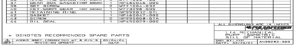
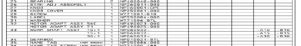
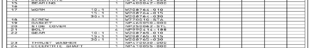
24 12. Parts Diagrams and Parts Lists 20
25 21
26 22

27 23
28 24
29 13. Maintenance Log 25
 292-8000 Fax (585) 424-5619 Bulletin IOM-PN-LCM-0403 http://www.pulsa.com pulsa@idexcorp.")
30 Engineered Pump Operations 2883 Brighton-Henrietta Townline Road Rochester, NY Telephone (585) Fax (585) Bulletin IOM-PN-LCM Rev D 26
Installation, Operation, & Maintenance Instruction. Model DC7. Bulletin #: IOM-DC C
 Installation, Operation, & Maintenance Instruction Model DC7 Bulletin #: IOM-DC7-0407- C Manufacturers of Quality Pumps, Controls, and Systems STANDARD PUMP OPERATIONS 27101 Airport Road Punta Gorda, FL
Installation, Operation & Maintenance Manual. Models: GLM7 PULSA GLM MECHANICAL DIAPHRAGM METERING PUMP. Bulletin: IOM-GLM-5001-Rev.
 Installation, Operation & Maintenance Manual Models: GLM7 Bulletin: IOM-GLM-5001-Rev.B PULSA GLM MECHANICAL DIAPHRAGM METERING PUMP Pulsafeeder Factory Service Policy Should you experience a problem with
Installation Operation Maintenance Instruction
 Installation Operation Maintenance Instruction Models DC2, 3, 4, 5, and 6 sales@novatech-usa.com www.novatech-usa.com Tel: (866) 433-6682 Fax: (866) 433-6684 Tel: (281) 359-8538 Fax: (281) 359-0084 Mechanical
Installation, Operation & Maintenance Supplement Instruction. Bulletin No.: IOMS-PUL PULSA Series 7120V DRIVE MOTOR INSTALLATION
 Installation, Operation & Maintenance Supplement Instruction Bulletin No.: IOMS-PUL-1012 PULSA Series 7120V DRIVE MOTOR INSTALLATION Copyright 2001-2015 Pulsafeeder, Inc. All rights reserved. ii Conventions
Installation Operation Maintenance Instruction
 Installation Operation Maintenance Instruction Bulletin #: PR IOM 0802 - D Hydraulic Diaphragm Metering Pump PULSAR Factory Service Policy Should you experience a problem with your PULSAR pump, first consult
Installation, Operation & Maintenance Instruction. Models: FMP Series 30, 40, 50. PeriFlo FMP PERISTALTIC PUMP. Bulletin #: IOM-PFL-4502
 Installation, Operation & Maintenance Instruction Models: FMP Series 30, 40, 50 Bulletin #: IOM-PFL-4502 PeriFlo FMP PERISTALTIC PUMP Pulsafeeder Factory Service Policy Should you experience a problem
Installation, Operation & Maintenance Manual. Bulletin: IOM-PUL-1500-Rev.E PULSAR HYDRAULIC DIAPHRAGM METERING PUMPS
 Installation, Operation & Maintenance Manual Bulletin: IOM-PUL-1500-Rev.E PULSAR HYDRAULIC DIAPHRAGM METERING PUMPS PULSAR FACTORY SERVICE POLICY Should you experience a problem with your PULSAR pump,
Installation Operation Maintenance ADDENDUM
 Installation Operation Maintenance ADDENDUM Bulletin #: PS-IOM-HYPO2-0111-A FACTORY SERVICE POLICY If you are experiencing a problem with your Pulsafeeder pump, first review the IOM, and consult the troubleshooting
Installation Operation Maintenance ADDENDUM BULLETIN No. PS-IOM-HYP-0203-H
 Installation Operation Maintenance ADDENDUM BULLETIN No. PS-IOM-HYP-0203-H USER NOTE: This addendum serves as additional information for Pulsafeeder PULSAR and PULSAR Shadow metering pumps equipped with
INSTALLATION OPERATION MAINTENANCE INSTRUCTION. BULLETIN No IOM-2000 Rev. C i. Hydraulic Diaphragm Metering Pump
 INSTALLATION OPERATION MAINTENANCE INSTRUCTION BULLETIN No. 9490-IOM-2000 Rev. C 9490 i Hydraulic Diaphragm Metering Pump PULSA SERIES GUARANTEE Should you experience a problem with your Pulsafeeder pump,
Installation, Operation & Maintenance Manual. Bulletin: IOM-PSRM-1501 REV B. PULSAR Shadow MECHANICAL DIAPHRAGM METERING PUMP
 Installation, Operation & Maintenance Manual Bulletin: IOM-PSRM-1501 REV B PULSAR Shadow MECHANICAL DIAPHRAGM METERING PUMP PULSAR Factory Service Policy Should you experience a problem with your PULSAR
Installation, Operation & Maintenance Manual. Models: ChemTuff Series PeriFlo ChemTuff PERISTALTIC PUMP. IOM-PFL-4600-Rev.B
 Installation, Operation & Maintenance Manual Models: ChemTuff Series 10 22 IOM-PFL-4600-Rev.B PeriFlo ChemTuff PERISTALTIC PUMP Pulsafeeder Factory Service Policy Should you experience a problem with your
INSTALLATION OPERATION MAINTENANCE INSTRUCTION
 INSTALLATION OPERATION MAINTENANCE INSTRUCTION BULLETIN No. 680C ENGINEERED PUMP OPERATIONS 2883 Brighton Henrietta TL Road P.O. Box 22909 Rochester, New York, 14692-22909 USA Telephone (716) 292-8000
BULLETIN No.: PulsaPro 900-IOM-2009 Rev. J PulsaPro Control Addendum INSTALLATION OPERATION MAINTENANCE INSTRUCTIONS
 BULLETIN No.: PulsaPro 900-IOM-2009 Rev. J PulsaPro Control Addendum INSTALLATION OPERATION MAINTENANCE INSTRUCTIONS Manufacturers of Quality Pumps, Controls and Systems Pulsafeeder, Inc. 2883 Brighton
Installation, Operation & Maintenance Instruction. Models: GLM M1 6 PULSA GLM MECHANICAL DIAPHRAGM METERING PUMP. Bulletin #: IOM-GLM-1303-A
 Installation, Operation & Maintenance Instruction Models: GLM M1 6 Bulletin #: IOM-GLM-1303-A PULSA GLM MECHANICAL DIAPHRAGM METERING PUMP Pulsafeeder Factory Service Policy Pulsafeeder s Factory Service
Installation Operation Maintenance Instruction
 Installation Operation Maintenance Instruction Bulletin #: IOM-680 IOM-680 Rev B. i Table of Contents 1. INTRODUCTION... 1 1.1 How Things Work... 1 1.2 Hydraulically Balance Flat Diaphragm Design... 1
TWO-STAGE HYDRAULIC PUMP. RWP55-IBT-Air
 ORIGINAL INSTRUCTIONS Form No.1000458 5 SPX Corporation 5885 11th Street Rockford, IL 61109-3699 USA Tech. Services: (800) 477-8326 Fax: (800) 765-8326 Order Entry: (800) 541-1418 Fax: (800) 288-7031 Internet
PulsaPro. Installation, Operation & Maintenance Manual HYDRAULIC DIAPHRAGM METERING PUMPS. Bulletin: IOM-PRO-001
 PulsaPro HYDRAULIC DIAPHRAGM METERING PUMPS Installation, Operation & Maintenance Manual Bulletin: IOM-PRO-001 PULSAFEEDER FACTORY SERVICE POLICY Upon receipt of your new PulsaPro diaphragm metering pump,
INSTALLATION, OPERATION AND MAINTENANCE MANUAL (IOM)
") INSTALLATION, OPERATION AND MAINTENANCE MANUAL (IOM) IOM-1088 03-16 Model 1088 Vacu-Gard Blanketing Valve ISO Registered Company SECTION I I. DESCRIPTION AND SCOPE The Model 1088 Vacu-Gard is a tank blanketing
INSTALLATION, OPERATION AND MAINTENANCE MANUAL (IOM) IOM-1088 03-16 Model 1088 Vacu-Gard Blanketing Valve ISO Registered Company SECTION I I. DESCRIPTION AND SCOPE The Model 1088 Vacu-Gard is a tank blanketing
Installation, Operation and Maintenance Manual
 Installation, Operation and Maintenance Manual Manual Polymer Makedown Systems Manufacturers of Quality Pumps, Controls, and Systems Standard Product Operations 27101 Airport Rd., Punta Gorda, FL 33982
HAYWARD FLOW CONTROL TBH SERIES TRUE UNION BALL VALVE INSTALLATION, OPERATION AND MAINTENANCE INSTRUCTIONS
 HAYWARD FLOW CONTROL TBH SERIES TRUE UNION BALL VALVE INSTALLATION, OPERATION AND MAINTENANCE INSTRUCTIONS Pg. 1 of 10 PLEASE READ THE FOLLOWING INFORMATION PRIOR TO INSTALLING AND USING HAYWARD TBH SERIES
END SUCTION CENTRIFUGAL PUMPS
 OWNERS GUIDE TO INSTALLATION AND OPERATION FW000 009 Supersedes 07 END SUCTION CENTRIFUGAL PUMPS READ THESE INSTRUCTIONS CAREFULLY Read these installation instructions in detail before installing your
Model 8329 Table of Contents
 SERVICE & OPERATING MANUAL Original Instructions Instructions Sheet: 670991 Model 8329 Table of Contents Engineering Data and Temperature Limitations... 1 Performance Curve... 2 Dimensions... 3 Metric
MAINTENANCE MANUAL FOR THERMOSTATIC TEMPERATURE REGULATING VALVE TRAC STYLE P
 MANUAL NUMBER P-EFS-1 MAINTENANCE MANUAL FOR THERMOSTATIC TEMPERATURE REGULATING VALVE TRAC STYLE P TRAC Regulator Company Inc. 160 South Terrace Avenue Mount Vernon, New York USA 10550-2408 Phone: (914)
INSTRUCTION MANUAL INTERNAL GEAR PUMP TITAN G-4124A SERIES=> FLANGED TITAN G-124A SERIES => FLANGED MODELS:
 INSTRUCTION MANUAL INTERNAL GEAR PUMP TITAN G-4124A SERIES=> FLANGED TITAN G-124A SERIES => FLANGED MODELS: G-H, G-HL, G-K, G-KK, G-L, G-LQ, G-LL, GLS, G-Q, G-QS 1 Contents Maintenance Thrust bearing adjustment
Operating instructions Form no safety definitions
 Operating instructions Form no. 1000437 safety definitions safety symbols are used to identify any action or lack of action that can cause personal injury. Your reading and understanding of these safety
SERIES PC INSTRUCTION AND OPERATION MANUAL
 MEGGA SERIES PC INSTRUCTION AND OPERATION MANUAL Models PCT and PCF Close-coupled and frame-mounted single-stage horizontal end-suction pumps. WARNING: Read this manual before installing or operating this
Valtek Auxiliary Handwheels and Limit Stops
 Valtek Auxiliary s and Limit Stops Table of Contents Page 1 General information 2 Installation 2 Side-mounted handwheels, size 25 and 50 (linear actuators) 3 Side-mounted handwheels, size 100 and 200 (linear
DC Variable Speed Drive Panel
 DC Variable Speed Drive Panel Installation, Operation & Maintenance Instruction Manual Bulletin #: CC-IOM-0103-D Manufacturers of Quality Pumps, Controls and Systems ENGINEERED PUMP OPERATIONS 2883 Brighton
DO NOT INSTALL, OPERATE, OR MAINTAIN AN ATI PRODUCT UNLESS TRAINED AND QUALIFIED IN PRODUCT AND ACCESSORY INSTALLATION, OPERATION AND MAINTENANCE.
 IOM Supplement IOMS003 ATI HO1/HO2 HYDRAULIC OVERRIDE Scope of Supplement This supplement is intended to assist those who are involved with the installation, operation and maintenance of ATI Linear Actuators
I & M Mark 78 Series. Ideal Installation. Start-Up. Installation & Maintenance Instructions for Mark 78 Control Valves (1-1/2-2 )
") I & M Mark 8 Series 0 Wasson Road Cincinnati, OH 4509 USA Phone 5-5-5600 Fax 5-8-005 info@richardsind.com www.jordanvalve.com Installation & Maintenance Instructions for Mark 8 Control Valves (-/ - ) Warning:
I & M Mark 8 Series 0 Wasson Road Cincinnati, OH 4509 USA Phone 5-5-5600 Fax 5-8-005 info@richardsind.com www.jordanvalve.com Installation & Maintenance Instructions for Mark 8 Control Valves (-/ - ) Warning:
M-1115S Series Fuel Pump
 SAVE THESE INSTRUCTIONS M-1115S Series Fuel Pump Owner s Manual TABLE OF CONTENTS General Information...2 Safety Instructions...2 Installation...3 Operation...4 Maintenance...5 Repair...5 Troubleshooting...9
I & M Mark 78 Series. Ideal Installation. Start-Up. Installation & Maintenance Instructions for Mark 78 Control Valves (1/2-1 )
") I & M Mark 8 Series 30 Wasson Road Cincinnati, OH 4509 USA Phone 53-533-5600 Fax 53-8-005 info@richardsind.com www.jordanvalve.com Installation & Maintenance Instructions for Mark 8 Control Valves (/ -
I & M Mark 8 Series 30 Wasson Road Cincinnati, OH 4509 USA Phone 53-533-5600 Fax 53-8-005 info@richardsind.com www.jordanvalve.com Installation & Maintenance Instructions for Mark 8 Control Valves (/ -
Installation, Operation & Maintenance Instruction Bulletin #: IOM-NMG-0804 Rev D
 Installation, Operation & Maintenance Instruction Bulletin #: IOM-NMG-0804 Rev D Manufacturers of Quality Pumps, Controls, and Systems ENGINEERED PUMP OPERATIONS 2883 Brighton Henrietta Townline Road Rochester,
Crispin Valves Operating Guide. Crispin
 Crispin Valves Operating Guide Crispin Since 1905 Crispin Multiplex Manufacturing Co. 600 Fowler Avenue Berwick, PA 18603 1-800-AIR-VALV T: (570) 752-4524 F: (570) 752-4962 www.crispinvalve.com sales@crispinvalve.com
GH-BETTIS SERVICE INSTRUCTIONS DISASSEMBLY & REASSEMBLY FOR MODELS HD521-M4, HD721-M4 AND HD731-M4 DOUBLE ACTING SERIES PNEUMATIC ACTUATORS
 GH-BETTIS SERVICE INSTRUCTIONS DISASSEMBLY & REASSEMBLY FOR MODELS HD521-M4, HD721-M4 AND HD731-M4 DOUBLE ACTING SERIES PNEUMATIC ACTUATORS WITH HYDRAULIC CONTROL PACKAGE PART NUMBER: SE-023 REVISION:
Installation Operation Maintenance Instruction
 Installation Operation Maintenance Instruction Bulletin #: IOM-680 IOM-880 i Table of Contents 1. INTRODUCTION... 1 1.1 How Things Work... 1 1.2 Hydraulically Balance Flat Diaphragm Design... 1 1.3 Reagent
SERVICE PARTS LIST SPECIFY CATALOG NO. AND SERIAL NO. WHEN ORDERING PARTS 13 HP DIRECT DRIVE PRESSURE WASHER CATALOG NO
 SPECIFY CATALOG NO. AND SERIAL NO. WHEN ORDERING PARTS HP DIRECT DRIVE PRESSURE WASHER CATALOG NO. 555-22 SERVICE PARTS LIST STARTING SERIAL NUMBER B06A REVISED BULLETIN PAGE OF BULLETIN NO. 5-20-000 DATE
AIR/HYDRAULIC INJECTION GUN MODEL INSTRUCTIONS
 I. OPERATION & DESCRIPTION The Air / Hydraulic Injection Gun is a high-pressure tool that should be used with caution and according to these instructions. IMPORTANT: The Gun is 0,000 psi rated. Do not
Instruction Manual PN-Z PACKED PLUNGER PUMP. This Manual should be made available to person responsible for installation, maintenance and operation.
 MILTON ROY INDIA (P) LTD Metering Pumps Instruction Manual PN-Z PACKED PLUNGER PUMP This Manual should be made available to person responsible for installation, maintenance and operation. PUMP MODEL: SERIAL
Pump Operating and Maintenance Manual - Models
 Pump Operating and Maintenance Manual - Models 78-00111 - 78-0057 Thank you for purchasing the SDI Diaphragm Pump manufactured by Comet Pump. Comet produces quality products which are safe, efficient and
INSTALLATION & MAINTENANCE MODEL mm
 MODEL 65-25mm INSTALLATION INSTRUCTIONS CAUTION: Installation of Backflow Preventers must be performed by qualified, licensed personnel. The installer should be sure the proper device has been selected
LIQUIDYNAMICS Light Viscosity Bulk Transfer Cart
 This manual contains important warnings and information. READ AND KEEP FOR REFERENCE. LIQUIDYNAMICS Light Viscosity Bulk Transfer Cart Instruction & Parts Manual This Manual Covers P/N 33271 P/N 33271
LAWN SPRINKLER, IRRIGATION PUMP
 LAWN SPRINKLER, IRRIGATION PUMP MODEL #, SP0P, SP5P, SP20P, EL0P, EL5P, EL20P SAFETY INFORMATION Please read and understand this entire manual before attempting to assemble, operate or install the product.
PULSA GLM ENGINEERED PRODUCTS. Mechanical Diaphragm. Max Flow: to 3,200 LPH (845 GPH) Pressure: 12 bar (175 psi) Temperature: 0-45 C ( F)
 Pressure: 12 bar (175 psi) Temperature: 0-45 C ( F)") ENGINEERED PRODUCTS Max Flow: to 3,200 LPH (845 GPH) Pressure: 12 bar (175 psi) Temperature: 0-45 C (32-113 F) Accuracy: +/- 2% of Set Point PULSA GLM Mechanical Diaphragm Metering Pump Mechanical Diaphragm
ENGINEERED PRODUCTS Max Flow: to 3,200 LPH (845 GPH) Pressure: 12 bar (175 psi) Temperature: 0-45 C (32-113 F) Accuracy: +/- 2% of Set Point PULSA GLM Mechanical Diaphragm Metering Pump Mechanical Diaphragm
Model Table of Contents. SERVICE & OPERATING MANUAL Original Instructions. Instructions Sheet:
 SERVICE & OPERATING MANUAL Original Instructions Instructions Sheet: 670989 Model 8324 Table of Contents Engineering Data and Temperature Limitations... 1 Performance Curve... 2 Dimensions... 3 Metric
GH-BETTIS OPERATING & MAINTENANCE INSTRUCTIONS DISASSEMBLY & ASSEMBLY FOR THE T80X-M4-S DOUBLE ACTING SERIES HYDRAULIC ACTUATORS
 GH-BETTIS OPERATING & MAINTENANCE INSTRUCTIONS DISASSEMBLY & ASSEMBLY FOR THE T80X-M4-S DOUBLE ACTING SERIES HYDRAULIC ACTUATORS -S INDICATES CYLINDERS ARE IN TANDEM PART NUMBER: 100121 REVISION "A" ECN
1/2" AIR DRIVEN DIAPHRAGM PUMP
 1/2" DRIVEN DIAPHRAGM PUMP OPERATION AND SERVICE GUIDE O-1225D NOV. 2008 Page 1 of 6 Refer to Bulletin P-605, Parts List P-9151 DRIVEN, DOUBLE DIAPHRAGM PUMP MANUAL Congratulations on purchasing one of
Low Profile J Series Power Unit with Vane Pump
 Low Profile J Series Power Unit with Vane Pump READ ALL INSTRUCTIONS CAREFULLY BEFORE ATTEMPTING TO ASSEMBLE, INSTALL, OPERATE OR MAINTAIN THE PRODUCT DESCRIBED. PROTECT YOURSELF AND OTHERS BY OBSERVING
Model DFR 070/156/220 Rotary Actuator
 Figure 1 DFR 156 TABLE OF CONTENTS General 2 Actuator Assembly 18 Scope 2 Bushing / Yoke Assembly 18 Principles of Operation 2 Spring Barrel Assembly 18 Safety Caution 2 Diaphragm Plate Assembly 20 Specifications
Electronic Metering Pump
 Electronic Metering Pump Pressure (PSI) Pressure (BAR) Pulsafeeder Expertise Technology is the key to delivering responsible products to the markets that we serve. Leading the way in the development of
I & M 8000 Series. Ideal Installation Schematic. Preferred Installation. Trouble Shooting
 I & M 8000 Series 3170 Wasson Road Cincinnati, OH 45209 USA Phone 513-533-5600 Fax 513-871-0105 lowflow@richardsind.com www.lowflowvalve.com Installation & Maintenance Instructions for 8000 Series Low
Apollo Standard Port, Full Port & One Piece Flanged Ball Valves Installation, Operation, & Maintenance Guide
 I854000.F M16005 Apollo Standard Port, Full Port & One Piece Flanged Ball Valves Introduction This manual presents guidelines for the Installation, Operation and Maintenance of manual and automated Apollo
SELF PRIMING CHEMICAL SERVICE PUMPS
 SELF PRIMING CHEMICAL SERVICE PUMPS INSTALLATION AND OPERATING INSTRUCTIONS This Manual covers: SELF PRIMING MODEL RANGE J50ECX TO J250ECX STAINLESS STEEL*, and NON METALLIC SEAL PUMP MODEL: SERIAL NO:
NECO Pumping Systems
 INSTALLATION OPERATION & MAINTENANCE INSTRUCTIONS For Your NECO Pumping Systems Fuel Oil Transfer System THIS COMPLETELY ASSEMBLED, TESTED, PACKAGED SYSTEM IS OF THE HIGHEST QUALITY AND DESIGN. TO OBTAIN
SD Bendix E-10PR Retarder Control Brake Valve DESCRIPTION. OPERATION - Refer to Figure 2
 SD-03-832 Bendix E-10PR Retarder Control Brake Valve MOUNTING PLATE SUPPLY 4 PORTS ELECTRICAL AUXILIARY DESCRIPTION TREADLE RETARDER CONTROL SECTION EXHAUST DELIVERY 4 PORTS FIGURE 1 - E-10PR RETARDER
INSTALLATION AND OPERATING MANUAL
 Publication T3-76, Rev. 1 Dated: May 9, 21 INSTALLATION AND OPERATING MANUAL MODEL: T3-I TURBOTWIN Engine Air Starter AN96-419 From Tech Development Inc 68 Poe Ave. Dayton OH 45414 Tel: (937) 898-96 Fax:
HIGH PRESSURE CONTROL VALVE PISTON BALANCED
 PISTON BALANCED All Rights Reserved. All contents of this publication including illustrations are believed to be reliable. And while efforts have been made to ensure their accuracy, they are not to be
TECHNICAL SERVICE MANUAL GENERAL PURPOSE BRACKET MOUNTED PUMPS SERIES 115 MODELS G, GX2, H and HX4
 TECHNICAL SERVICE MANUAL GENERAL PURPOSE BRACKET MOUNTED PUMPS SERIES 115 MODELS G, GX2, H and HX4 SECTION 2 BULLETIN TSM-115-C ISSUE A CONTENTS Special Information 2 Maintenance 2 Packed Pump Breakdown
Ideal Installation. I & M Mark 67 (1/2 6 ) Control Line. Installation & Maintenance Instructions for Mark 67 Pressure Regulators
 Control Line. Installation & Maintenance Instructions for Mark 67 Pressure Regulators") I & M Mark (/ ) 0 Wasson Road Cincinnati, OH 0 USA Phone --00 Fax -8-00 info@richardsind.com www.jordanvalve.com Installation & Maintenance Instructions for Mark Pressure Regulators Warning: Jordan Valve
I & M Mark (/ ) 0 Wasson Road Cincinnati, OH 0 USA Phone --00 Fax -8-00 info@richardsind.com www.jordanvalve.com Installation & Maintenance Instructions for Mark Pressure Regulators Warning: Jordan Valve
To ensure proper installation, digital pictures with contact information to before startup.
 Check List for Optimal Filter Performance? There should be no back-pressure on the flush line. A 1 valve should have a 2 waste line, and 2 valve should have a 3 waste line. Do not use rubber hosing or
Model DF269 Control Valve
 Figure 1 DF269 Control Valve TABLE OF CONTENTS Introduction 2 Fail Open Actuator Disassembly 6 General 2 Body and Packing Reassembly 7 Scope 2 Fail Closed Actuator Resassembly 8 Specifications 3 Fail Open
D/G-35 Maintenance. Shutdown Procedure During Freezing Temperatures. Daily. Periodically
 D/G-35 Maintenance NOTE: The numbers in parentheses are the Reference Numbers on the exploded view illustrations found later in this manual. Daily Check the oil level and the condition of the oil. The
PLUNGER PUMP SERVICE MANUAL
 PLUNGER PUMP SERVICE MANUAL INSTALLATION AND START-UP INFORMATION Optimum performance of the pump is dependant upon the entire liquid system and will be obtained only with the proper selection, installation
BOILER FEED SYSTEM OPERATION AND MAINTENANCE MANUAL
 BOILER FEED SYSTEM OPERATION AND MAINTENANCE MANUAL IMPORTANT These instructions are intended as a guide for the Installing Contractor and as a reference for the Operator, Owner and Serviceman. RETAIN
INSTALLATION AND OPERATING
 Publication T5-704, Rev. 4 Dated: November 1, 2006 INSTALLATION AND OPERATING MANUAL T50-P TURBOTWIN Engine Air Starter AN 99-448 TABLE OF CONTENTS Section Subject Page 1.0 General Information. 1 2.0 Orientation
PLUNGER PUMP SERVICE MANUAL
 PLUNGER PUMP SERVICE MANUAL INSTALLATION AND START-UP INFORMATION Optimum performance of the pump is dependant upon the entire liquid system and will be obtained only with the proper selection, installation
INSTALLATION AND OPERATING MANUAL
 Dated: May 10, 2001 INSTALLATION AND OPERATING MANUAL MODEL: T30-Y TURBOTWIN Engine Air Starter From Tech Development Inc AN96-425 6800 Poe Ave. Dayton OH 45414 Tel: (937) 898-9600 Fax: (937) 898-8431
Model DF233 Control Valve
 Figure 1 DF233 Control Valve TABLE OF CONTENTS Introduction 2 Body and Packing Reassembly 7 Specifications 3 Fail Closed Actuator Reassembly 8 Valve Sizes 3 Fail Open Actuator Reassembly 9 Unpacking 4
KP-C Series. Close Coupled End Suction Centrifugal Pumps. Installation, Operation and Maintenance
 KP-C Series Close Coupled End Suction Centrifugal Pumps Installation, Operation and Maintenance PUMP MODEL NOMENCLATURE KP - 8 x 6 x 16 - E C - AI - BCM Pump Series Suction Pipe Size (in) Discharge Pipe
Instructions for Installing and Operating Clark Reliance EA100 Series Levalarm
 Section: R500.532F Bulletin: 532F Date: 7/1/2015 Supersedes: 532E Instructions for Installing and Operating Clark Reliance EA100 Series Levalarm This manual covers the following model numbers: EA100D,
Maintenance Manual Reduced Pressure Assembly Models 860 & 880V 2 1 /2" 10"
 IOM-F-860_880V INSTALLATION, OPERATION, MAINTENANCE Maintenance Manual Reduced Pressure Assembly Models 860 & 880V 2 1 /2" 10" 860 880V Standard Configuration 880V Vertical Configuration INDEX Vandalism..............................................
Troubleshooting, Service Tips, And Major Improvements For Hydrostatic Transmissions (Special Edition){3200}
{3200}") Page 1 of 75 Troubleshooting, Service Tips, And Major Improvements For Hydrostatic Transmissions (Special Edition){3200} 943, 953, 963, 973 Loaders Introduction The hydrostatic transmissions used in 943,
Page 1 of 75 Troubleshooting, Service Tips, And Major Improvements For Hydrostatic Transmissions (Special Edition){3200} 943, 953, 963, 973 Loaders Introduction The hydrostatic transmissions used in 943,
Steam/Water Washdown Units Safety and Operation Installation and Maintenance Instructions
 INSTALLATION AND MAINTENANCE INSTRUCTIONS IM-8-002-US October 2016 Steam/Water Washdown Units Safety and Operation Installation and Maintenance Instructions These instructions should be read by the Company
Farval. Dualine Installation System Start-Up. Bulletin DL300 BIJUR DELIMON INTERNATIONAL
 Farval Dualine Installation System Start-Up Bulletin DL300 BIJUR DELIMON INTERNATIONAL 2685 Airport Road Kinston, NC 28504 Tel. 800-227-1063 Fax: 252-527-9232 website: www.bijurdelimon.com DC1-1 SECTION
WARCO CHEMAG SERIES GH FILTERS
 WARCO CHEMAG SERIES GH FILTERS High Performance Pleated & Bag Type Filtration Systems INSTALLATION, OPERATION, AND MAINTENANCE INSTRUCTIONS Thank you for your purchase of a WARCO Series GH Filtration System.
M-3025CB-AV Fuel Pump
 SAVE THESE INSTRUCTIONS M-3025CB-AV Fuel Pump Owner s Manual TABLE OF CONTENTS General Information... 2 Safety Instructions... 2 Installation... 3 Operation... 4 Maintenance... 4 Repair... 5 Troubleshooting...
GT-200 GATE VALVES PN16, Screwed end
 Document No. : MD-QO-04-281 Date : 2009/07 /17 Version : 1.0 GT-200 GATE VALVES PN16, Screwed end USER MANUAL Modentic Industrial Corporation 14F-1,No.57Taya Rd.,Taichung,Taiwan,R.O.C. Email:modentic@ms9.hinet.net
Manual. MicroTron. Series C. Installation Maintenance Repair Manual. Chemical Metering Pump
 Manual MicroTron Series C Chemical Metering Pump Installation Maintenance Repair Manual Advantage Controls P.O.Box 1472 Muskogee, OK 74402 Phone: 800-743-7431 Fax: 888-686-6212 www.advantagecontrols.com
GL Ludemann Y-Strainers
 GL Ludemann Y-Strainers Installation, Operation and Maintenance Manual English Issue 1-03/2014 - Page 1/7 GENERAL These instructions are for installing, operation and maintenance of Y-strainers fabricated
Vane Pumps. Single Stage Single and Double Vane Pumps. Vickers. Overhaul Manual
 Vickers Vane Pumps Overhaul Manual Single Stage Single and Double Vane Pumps V14, 124, 134,144 V19, 129, 139, 149 V15, 125, 135, 145 V35*, 36*, 45*, 46* V18, 128, 138, 148 (V)VF-**-**, (V)VG-**-** Reprinted
Installation and Service Instructions. ST Series Pumps
 Installation and Service Instructions ST Series Pumps! WARNING READ MANUAL before operating or working on a Tuthill ST Series pump. Page 2 of 24 4/24/03 Table of Contents Page 4 Page 5 Page 5 Page 6 Page
NECO Pumping Systems
 INSTALLATION OPERATION & MAINTENANCE INSTRUCTIONS For Your NECO Pumping Systems PACKAGED CIRCULATING SYSTEM THIS COMPLETELY ASSEMBLED, TESTED, PACKAGED CIRCULATING SYSTEM IS OF THE HIGHEST QUALITY AND
HexPro Series Low Profile Wrenches
 HexPro Series Low Profile Wrenches Operation and Maintenance Manual Model 2HP 4HP 8HP 14HP 30HP www.torquetoolsinc.com Use the HEXPRO Series Low Profile Wrenches Model 2HP 4HP 8HP 14HP 30HP to install
An IDEX Water & Wastewater Business. pulsafeeder.com. Electronic Metering Pump
 An IDEX Water & Wastewater Business pulsafeeder.com Electronic Metering Pump Pressure (PSI) Pressure (BAR) Pulsafeeder Expertise Technology is the key to delivering responsible products to the markets
Operating Manual for Rotary Gear Pumps CMI, S.A. (Mendaro, Guipuzkoa, Spain)
") Operating Manual for Rotary Gear Pumps CMI, S.A. (Mendaro, Guipuzkoa, Spain) Pre-Installation 1. Choose a location that is easily accessible for pump servicing. Ensure adequate electrical service is available.
Operating Manual for Rotary Gear Pumps CMI, S.A. (Mendaro, Guipuzkoa, Spain) Pre-Installation 1. Choose a location that is easily accessible for pump servicing. Ensure adequate electrical service is available.
D/G-03 Maintenance. Shutdown Procedure During Freezing Temperatures. Daily. Periodically
 D/G-03 Maintenance NOTE: The numbers in parentheses are the Ref. Nos. on the illustrations in the Parts Manual. Daily Check the oil level and the condition of the oil. The oil level should be 3/4 in. (20
Fisher 657 Diaphragm Actuator Sizes and 87
 Instruction Manual 657 Actuator (30-70 and 87) Fisher 657 Diaphragm Actuator Sizes 30 70 and 87 Contents Introduction... 1 Scope of Manual... 1 Description... 2 Specifications... 2 Installation... 3 Mounting
BETTIS SERVICE INSTRUCTIONS DISASSEMBLY AND REASSEMBLY FOR CB-SR-S SEISMIC SPRING RETURN SERIES PNEUMATIC ACTUATORS
 BETTIS SERVICE INSTRUCTIONS DISASSEMBLY AND REASSEMBLY FOR CB-SR-S SEISMIC SPRING RETURN SERIES PNEUMATIC ACTUATORS PART NUMBER: 102264 REVISION: "C" DATE: November 2000 Page 1 of 11 1.0 INTRODUCTION 1.1
3" & 4" Cast Iron Self-Priming Centrifugal Pump Instruction Manual
 12 3" & 4" Cast Iron Self-Priming Centrifugal Pump Instruction Manual 333 & 444 Series Read these instructions and the instructions covering operation of the pump drive unit. Do not operate the gas engine
ROOTS Meters Series B3 Meter Models 8C175-56M175
 ROOTS Meters Series B3 Meter Models 8C175-56M175 Refer to IOM-B3 for Complete Instructions IS:B3 3.03 RECEIVING, HANDLING AND STORAGE ROOTS rotary positive displacement gas meters are precision measurement
OPERATION MANUAL NT50 NOMAD TRANS-FLO AIR-OPERATED DOUBLE DIAPHRAGM PUMPS. A JDA Global Company. 7/11 rev. 1
 OPERATION MANUAL NT50 NOMAD TRANS-FLO AIR-OPERATED DOUBLE DIAPHRAGM PUMPS A JDA Global Company 7/11 rev. 1 CAUTION SAFETY POINTS TEMPERATURE LIMITS: Neoprene -17.8 C to 93.3 C 0 F to 200 F Buna-N -12.2
Troubleshooting. This section outlines procedures for troubleshooting problems with the operation of the system:
 Troubleshooting This section outlines procedures for troubleshooting problems with the operation of the system: 4.1 System Error Messages... 4-2 4.2 Prep Station Troubleshooting... 4-6 4.2.1 Adapter Not
END SUCTION CENTRIFUGAL PUMPS
 OWNERS GUIDE TO INSTALLATION AND OPERATION END SUCTION CENTRIFUGAL PUMPS FW000 0 Supersedes 009 READ THESE INSTRUCTIONS CAREFULLY Read these installation instructions in detail before installing your pump.
SERVICING INSTRUCTIONS
 TSP Series 66 Triplex Plunger Pump SERVICING INSTRUCTIONS TRIPLEX TRIPLEX SERVICING PUMP PROCEDURES Valve Replacement: All inlet and discharge valves can be serviced without disrupting the inlet or discharge
Temperature Sensor Series
 GENERAL DESCRIPTION The patented* No. 85026-Series Temperature Sensor contains a two-position valve operated by temperature variations around the integral sensing bulb. It is used to vent or block a pneumatic
CONTENTS. VIKING PUMP, INC. A Unit of IDEX Corporation Cedar Falls, IA USA SECTION TSM 710.1
 TECHNICAL SERVICE MANUAL industrial heavy duty motor speed pumps SERIES 4076 AND 4176 SIZES hle, ate and ale SECTION TSM 710.1 PAGE 1 of 8 ISSUE B CONTENTS Introduction....................... 1 Safety
for NEPTUNE SERIES 600 dia-pump MODELS 610 thru 647
 for NEPTUNE SERIES 600 dia-pump MODELS 610 thru 647 NEPTUNE CHEMICAL PUMP CO., INC. Lansdale, PA. 19446 * Tel.: 215-699-8700 * FAX: 215-699-0370 WARNING LOCKOUTS ARE REQUIRED BEFORE SERVICING THIS EQUIPMENT.
Low Profile Wrenches Operation and Maintenance Manual
 Low Profile Wrenches Operation and Maintenance Manual http://www.torquetoolsinc.com Use the HEXPRO Series Low Profile Wrenches Model 2HP 4HP 8HP 14HP 30HP to install and remove large bolts that have minimal
Spin Finish Series Gear Pumps. Zenith Pumps. Installation, Care And Maintenance. Zenith Finish Metering Applications
 Zenith Pumps Spin Finish Series Gear Pumps Installation, Care And Maintenance Zenith Finish Metering Applications Thoroughly read and understand this entire manual before installation and operation of