Waukee AutoLube User Manual
|
|
|
- Esmond Lynch
- 6 years ago
- Views:
Transcription


1 Waukee AutoLube User Manual
2 Manual #: 016 Initial Release {4/24/2008} Rev No: C Date: 12/22/10 For assistance please contact: Waukee Engineering Co. Inc. TEL: FAX: sales@waukeemeters.com File: Manu016 Carburetor User Manual 2
3 WARNING Thank you for purchasing equipment from Waukee Engineering a member of United Process Controls. We want your new equipment to operate safely. Anyone who uses this equipment should read this publication (and any other relevant publications) before installing or operating the equipment. To minimize the risk of potential safety problems, you should follow all applicable local and national codes that regulate the installation and operation of your equipment. These codes vary from area to area and usually change with time. It is your responsibility to determine which codes should be followed, and to verify that the equipment, installation, and operation is in compliance with the latest version of these codes. At a minimum, you should follow all applicable sections of the National Fire Code, National Electrical Code, and codes of the National Electrical Manufacture s Association (NEMA). There may be local regulatory or government offices that can also help determine which codes and standards are necessary for safe installation and operation. Equipment damage or serious injury to personnel can result from failure to follow all applicable codes and standards. We do not guarantee the products described in this publication are suitable for your particular application, nor do we assume any responsibility for you product design, installation, or operation. If you have any questions concerning the installation or operation of this equipment, or if you need additional information, please call us at WARNING: Read this manual thoroughly before using Autolube. File: Manu016 Carburetor User Manual 3
4 TABLE OF CONTENTS INTRODUCTION... 3 DESCRIPTION... 4 SPECIFICATIONS... 4 INSTALLATION... 5 MOUNTING... 5 PLUMBING... 5 WIRING GUIDELINES... 6 WIRING... 6 OPERATION... 7 FILLING THE OIL RESERVOIR... 7 STARTING THE COMPRESSOR... 7 ADJUSTING THE OIL FLOW RATE... 7 PARTS LIST... 8 APPENDIX A - DRAWINGS File: Manu016 Carburetor User Manual 4
5 INTRODUCTION The Purpose of this Manual Thank You for Purchasing a Waukee Automatic Lubricator. This Manual shows you how to install and maintain Waukee s Automatic Lubricator. This manual contains important information and should be read and understood by all individuals who install, use or service this equipment. Supplemental Manuals The Waukee Compressor/Mixor Manual #3254 manual contains technical information as well as precautions regarding use of Waukee s Automatic Lubricator with a Waukee Compressor. Technical Support We strive to make our manuals the best in the industry. We rely on your feedback to let us know if we are reaching our goal. If you cannot find the solution to your particular application, or, if for any reason you need technical assistance, please call us at: Our technical support group will work with you to answer your questions. They are available Monday through Friday from 8:00 A.M. to 4:30 P.M. Central Standard Time. We also encourage you to visit our web site where you can find technical and nontechnical information about our products and company. If you have a comment, question or suggestion about any of our products, services, or manuals, please or contact us by phone. Conventions Used When you see the exclamation point icon in the left-hand margin, the paragraph to its immediate right will be a warning. This information could prevent injury, loss of property, or even death in extreme cases. Any warning in this manual should be regarded as critical information that should be read in its entirety. The word WARNING or CAUTION in boldface will mark the beginning of the text. File: Manu016 Carburetor User Manual 5
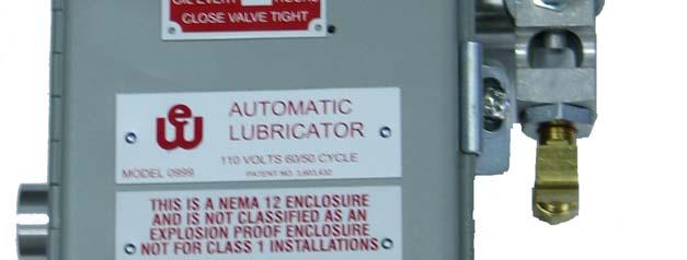
6 DESCRIPTION The Waukee Automatic Lubricator controls the amount of lubricating oil supplied to the compressor. The Automatic Lubricator is comprised of an electronic timer, an oil reservoir, and a solenoid valve. The unit is designed to automatically lubricate Waukee compressors that require lubrication. This unit insures that the compressor is properly lubricated to provide maximum life for the compressor vanes. Green Lamp Power ON Oil Reservoir Yellow Lamp Lubricating Oil Fill Port Oil Control Valve Manual Lubrication Button Solenoid Valve Oil Feed Sight Window Figure 1 Voltage: 115VAC, 50/60 Hz SPECIFICATIONS Power Consumption: 0.2 amps File: Manu016 Carburetor User Manual 6
7 INSTALLATION Mounting If the Automatic Lubricator was purchased with a compressor it will already be mounted, otherwise mounting will be required if the unit was purchased separately. The Automatic Lubricator can be mounted onto the side of the compressor with the include mounting bracket as shown in Figure 2 or anywhere within 2-3ft. of the compressor. The Automatic Lubricator is a gravity feed type oiler, which requires the oiler to be mounted higher than the compressor in order to function properly. Plumbing The Automatic Lubricator requires only two plumbing connections, unless your oiler was preinstalled by Waukee. The first connection is the oil feed tube (Refer to Figure 2) Connect a ¼ copper tube from the solenoid valve to the 1/8 NPT port located on top of the compressor. The oil feed tubing should be kept as short and vertical as possible to provide the best performance. The second connection is the pressurized feedback (Refer to Figure 3) Connect a ¼ copper tube from the top of the oiler to the 1/8 NPT port located on the side of the compressor. Figure 3 ¼ Copper Tube Compression Fitting Mounting Bolts Mounting Bracket ¼ Oil Feed Tube Figure 2 1/8 NPT Port 1/8 NPT Tee 1/8 Plug ¼ Copper Tube ¼ Compression Fitting 1/8 Isolation Valve File: Manu016 Carburetor User Manual 7
8 Wiring Guidelines Your company may have guidelines for wiring installation. If so, you should check those before you begin the installation. Here are some general things to consider: Use the shortest wiring route whenever possible. Route the wiring through an approved cable housing to minimize the risk of accidental damage. Check local and national codes to choose the correct method for your application. CAUTION: To reduce the risk of electrical shock and also to prevent damage to the Automatic Lubricator. It is advised to turn off the supply power to the Automatic Lubricator before connecting or disconnecting any wires. Wiring The unit should be wired such that power is supplied to it only when the compressor is running. It is very important that power to the Automatic Lubricator is OFF when the compressor is not running. The recommended method for wiring the unit is to connect power through the normally open contacts of the motor starter of the compressor s drive motor. See Figure 4 for wiring. WARNING: If power is supplied to the unit while the compressor is off, excessive oil may build up in the compressor causing damage to the compressor and/or any components located downstream of the compressor. WARNING: The Unit is designed for use with 115VAC Single phase, 50/60Hz power ONLY!! Connection of any other power type may damage the unit and may subject personnel to shock or injury. Figure 4 File: Manu016 Carburetor User Manual 8
9 OPERATION Filling the Oil Reservoir Before opening the oil fill port, turn off the isolation valve on the feedback line. (See Figure 3) Remove the Oil fill plug (See Figure 5) and fill the oil reservoir with Waukee Compressor Oil. Part No s COIL-1 (pint), COIL-2 (quart) or COIL-3 (gallon). Once reservoir is full replace the oil fill plug and open the isolation valve. Figure 5 Oil Fill Port WARNING: Lack of or improper lubricating oil may cause damage to the compressor. Use Waukee Compressor Oil ONLY!! CAUTION: Before removing oil fill plug turn isolation valve OFF. Failure to turn isolation valve OFF will result in compressed gas leaking from the oiler and may cause a hazardous situation. Gas leaking from oiler may be flammable. WARNING: Make sure isolation valve is open after filling oil reservoir with oil and replacing the oil fill plug. If isolation valve is left closed oiler will not be able to drop oil and cause premature failure of the vanes. Starting the Compressor Every time the compressor is started, the Green Power On light on the Automatic Lubricator should be ON and remain on until the compressor is stopped. Also the Amber Lubricating light will illuminate for 4 seconds. During this 4 second time, oil should be seen dropping in the sight glass. The Automatic Lubricator is a ON-OFF cycle timer, it will start with a 4sec ON time and after the ON cycle completes it will remain OFF for a period of 1Hr. and will continue to cycle until power is removed. Adjusting the Oil Flow Rate The solenoid valve is factory set to provide the proper number of oil drops during the ON period of 4 seconds. To verify or adjust the oil flow rate, depress and hold the Manual Lubrication Button located on the left side of the Automatic Lubricator and adjust the Oil Control Valve to obtain the proper number of oil drops within a 15 second time interval. The number of drops required during the 15 second interval is displayed on the nameplate attached to the front of the Automatic Lubricator s enclosure. If the nameplate is unreadable or the Automatic Lubricator will be used on a different compressor that what it was ordered for, then refer to Table 1 on the following page to determine the proper amount of drops for your compressor. File: Manu016 Carburetor User Manual 9
10 TABLE 1 OIL RATE CHART IN DROPS OF OIL PER 15 SECOND PERIOD Number of Drops Required over a 15 second period Flow Output of Compressor Output Pressure 1psig (6.9kPa) Output Pressure 2psig (13.8kPa) Output Pressure 3psig (20.7kPa) 200CFH (5.6M3H) CFH (11.3M3H) CFH (17.0M3H) CFH (21.2M3H) CFH (28.3M3H) CFH (35.4M3H) CFH (42.5M3H) CFH (56.6M3H) CFH (84.9M3H) CFH (113.3M3H) CFH (141.6M3H) CFH (169.9M3H) CFH (198.2M3H) CFH (226.5M3H) PARTS LIST TABLE 2 PARTS LIST Description Part Number Amber Indicator Lamp Green Indicator Lamp Timer Board Solenoid Valve Assembly Manual Lubrication Button Support Bracket for A, B, and C Compressors Support Bracket for D, H, J, and E Compressors Support Bracket for F, G, and N Compressors Support Bracket for R, S, U, and W Compressors Compressor Oil, pint COIL-1 Compressor Oil, quart COIL-2 Compressor Oil, gallon COIL-3 File: Manu016 Carburetor User Manual 10
11 EXPRESS WARRANTY ON WAUKEE EQUIPMENT. WAUKEE warrants its products for a period of one (1) year from date of shipment from WAUKEE to the original purchaser to be free from defects in material and workmanship under normal recommended use, service, inspection and maintenance. Normal recommended use, service inspection and maintenance mean: system or other goods or services manufactured, sold or provided by WAUKEE; 4. Misapplication, misuse and failure to follow THE MANUAL or other literature, instructions or bulletins (including drawings) published or distributed prior to THE MANUAL. 1. Not to be used in excess of nor below the rated capacity, pressures and temperature ranges specified in the applicable quotation, purchase order, acknowledgment, marketing literature, nameplate(s), specification sheet or the Installation, Operation, Inspection and Maintenance Manual (THE MANUAL); 2. Using only clean liquids or gases (only liquids in liquid Flo-Meters and only gases in gas Flo-Meters); air and fuel gases used in mixing equipment to be clean and free of solids all as further explained in THE MANUAL; and 3. Installation, operation, inspection and maintenance in compliance with THE MANUAL; and 4. The WAUKEE products being used only in: a. Ambient environments lower than 132 Fahrenheit (54 Celsius) unless specifically designed and so labeled by WAUKEE for higher temperatures; and b. Non-corrosive environments; and c. Completely protected from moisture, rain, snow or other outside environments; and d. Not to be used below 32 Fahrenheit (0 Celsius) unless special precautions are taken for low temperature conditions as shown in THE MANUAL. 5. Being used only for applications permitted by THE MANUAL or other WAUKEE literature or special applications approved in a separate written authorization by WAUKEE. WARRANTY EXCEPTIONS This Warranty does not apply to damage caused by any or all of the following circumstances or conditions: The exclusive remedy under this Warranty or any other express warranty is the repair or replacement without charge for labor and materials of any WAUKEE parts found upon examination by WAUKEE to have been defective. Since certain WAUKEE equipment is heavy, bulky and not deliverable by U.S. mail or other parcel service, WAUKEE equipment may be returned only upon written consent of WAUKEE and then only to the location designated by WAUKEE. Generally such consent will be given only upon the condition that the customer assume and prepay all carrier charges and responsibility for damage in transit. Purchasers of WAUKEE products, equipment, goods or services waive subrogation on all items covered under their own or any other insurance. DISCLAIMER THIS WARRANTY IS EXCLUSIVE. WAUKEE EXPRESSLY DISCLAIMS ANY AND ALL OTHER WARRANTIES WHETHER EXPRESS OR IMPLIED INCLUDING ANY IMPLIED WARRANTY OF MERCHANTABILITY OR FITNESS FOR A PARTICULAR PURPOSE OR ANY PURPOSE. No person, including any dealer, seller or other representative of WAUKEE is authorized to make, on behalf of WAUKEE, any representations beyond those contained in WAUKEE literature and documents or to assume for WAUKEE any obligations or duties not contained in this Warranty and Warranty Policy. WAUKEE reserves the right to make design and other changes, modifications or improvements to its products, services, literature or systems, without any obligation, to furnish or install same on any previously sold or delivered products or systems. 1. Freight damage; 2. Parts, accessories, materials or components not obtained from nor approved in writing by WAUKEE; 3. Any consequential or incidental damages including but not limited to loss of use, loss of profits, loss of sales, increased costs, arising from the use of any product, File: Manu016 Carburetor User Manual 11
12 LIMITATION OF LIABILITY It is expressly agreed that the liability of WAUKEE is limited and WAUKEE does not function as an insurer. The purchaser and/or user agree that WAUKEE is not liable for loss, harm or damage due directly or indirectly to any occurrence or consequences therefrom. If WAUKEE should be found liable to anyone on any theory (except any express warranty where the remedy is set forth in Section 2 of this Warranty and Warranty Policy) for loss, harm or damage, the liability of WAUKEE shall be limited to the lesser of the actual loss, harm or damage or the purchase price of the involved WAUKEE equipment or service when sold (or when service performed) by WAUKEE to its customer. This liability is exclusive and regardless of cause or origin resulting directly or indirectly to any person or property from: 1. The performance or nonperformance of any obligations set forth in this Warranty and Warranty Policy: 2 Any agreement including specifications between WAUKEE and the customer; 3 Negligence, active, passive or otherwise of WAUKEE or any of its agents or employees; 4. Breach of any judicially imposed warranty or convenant of workmanship, durability or performance; and 5. Misrepresentation (under the Restatement, common law or otherwise) and/or strict liability involvement. 6. Liability for fraud-in-the-inducement. INFORMATION NECESSARY TO OBTAIN TECHNICAL ASSISTANCE. For WAUKEE to appropriately respond to a request for assistance or evaluation of customer or user operating difficulty. Please provide at a minimum the following information: 2. The date and from whom you purchased your WAUKEE equipment and your purchase order number. 3. State your difficulty, being sure to mention at least the following: 4. Application. 5. Input pressure where Flo-Meters or compressors are involved. 6. Condition of filters, strainers or screens, upstream or downstream of the WAUKEE equipment. 7. Gas or liquid temperatures and other ambient conditions at the time of the difficulty. 8. Type of lubrication being used (if any) - give specifics. 9. Any other relevant pressures including gauge readings both upstream and downstream of the WAUKEE equipment. 10. All electrical information available. 11. Performance activity. 12. Any other pertinent information. If a sketch would help explain the difficulty, please include one. WARRANTY FIELD SERVICE If warranty Field Service at the request of the purchaser or user is rendered and the difficulty is found not to be with WAUKEE's product, the purchaser shall pay the time and expense (at the prevailing rate at the time of the service) of WAUKEE's field representative(s). Charges for service, labor and other expenses that have been incurred by the purchaser, its customer or agent without written approval of WAUKEE will not be accepted. The OEM or other reseller is responsible for transmitting installation and operating instructions, THE MANUAL or other service literature supplied by WAUKEE with the equip 1. Serial number and type or model of meter, compressor or other equipment and all other data shown on the nameplate and on the specific component which appears to be involved in the difficulty; File: Manu016 Carburetor User Manual 12
13 APPENDIX A - DRAWINGS File: Manu016 Carburetor User Manual 13


14 Reach us at United Process Controls brings together leading brands to the heat treating industry including Waukee Engineering, Furnace Control, Marathon Monitors and Process-Electronic. We provide prime control solutions through our worldwide sales and services network with easy-toaccess local support. WAUKEE ENGINEERING COMPANY, INC. A member of United Process Controls 5600 West Florist Avenue, Milwaukee, WI 53218, U.S.A. Phone: Fax: sales@waukeemeters.com File: Manu016 Carburetor User Manual 14
Waukee Carburetor. USER MANUAL revision 4
 Waukee Carburetor USER MANUAL revision 4 Waukee Carburetor Rev 4 Page 2 Manual #: 015 Rev No: 4 Date: 29 March 2013 COPYRIGHT No part of this publication may be reproduced, transmitted, transcribed, stored
WAUKEE ENGINEERING Ratio Control Valve Installation And Operation Manual
 WAUKEE ENGINEERING Ratio Control Valve Installation And Operation Manual NOTICE This manual contains important safety information and should be read and understood by all installation personnel and all
INSTALLATION, INSTRUCTION AND SERVICE MANUAL
 INSTALLATION, INSTRUCTION AND SERVICE MANUAL Actuator/Brake/Trailer Dealer Please provide to consumer. Consumer Read and follow instructions. Keep with trailer for reference. Page 1 of 7 1. Introduction...
WAUKEE ENGINEERING Valve-Tronic 3.5 Installation And Operation Manual
 WAUKEE ENGINEERING Valve-Tronic 3.5 Installation And Operation Manual NOTICE This manual contains important safety information and should be read and understood by all installation personnel and all users
TERMS OF USE TERMS AND CONDITIONS. Plumbing and Heating Products (PL-WR)
") TERMS OF USE 1. Watts pricing and product data is subject to change without notice and such changes supersede all previous versions. 2. Watts data is to be used as provided. Watts is not responsible for
TERMS OF USE 1. Watts pricing and product data is subject to change without notice and such changes supersede all previous versions. 2. Watts data is to be used as provided. Watts is not responsible for
TITAN 13 x 2½ BRAKES DUO-SERVO AND FREE BACKING
 INSTALLATION INSTRUCTION AND SERVICE MANUAL Actuator/Trailer Dealer - Please provide these instructions to the consumer. Consumer - Read and follow these instructions. Keep them with the trailer for future
PREMIER, MARINE, & STANDARD
 INSTA LLATION INSTRUCTION AND SERVICE MANUAL I TITAN 12" x 2" BRAKES FREE BACKING. UNI-SERVO. DUO-SERVO PREMIER, MARINE, & STANDARD Limited Warranty TITAN Inc. ("TITAN') warrants its products to be free
Fifth Wheel Power Hitch Operations Manual
 Fifth Wheel Power Hitch Operations Manual ITD1253 Fifth Wheel Power Hitch 208 587 7960 www.intheditch.com This page is intentionally left blank. Operations Manual 1 TABLE OF CONTENTS TABLE OF CONTENTS...
INSTALLATION INSTRUCTIONS
 INSTALLATION INSTRUCTION AND SERVICE MANUAL Actuator/Trailer Dealer - Please provide these instructions to the consumer. Consumer - Read and follow these instructions. Keep them with the trailer for future
DODGE CUMMINS GDP Twin CP-3 Big Line Kit
 Installation Manual P/N 0306-TCP3 2003-07 DODGE CUMMINS GDP Twin CP-3 Big Line Kit Installation Instructions P/N 0306-TCP3 GDP Twin CP-3 Big Line Kit Installation PLEASE READ ALL INSTRUCTIONS BEFORE BEGINNING
L DODGE CUMMINS Maximizer System
 Installation Manual P/N 07509MAX 2007.5-09 6.7L DODGE CUMMINS Maximizer System Installation Instructions P/N 07509MAX GDP Big Line Kit Installation PLEASE READ ALL INSTRUCTIONS BEFORE BEGINNING INSTALLATION
DODGE CUMMINS GDP Big Line Kit
 Installation Manual P/N 9852BLK 1998.5-2002 DODGE CUMMINS GDP Big Line Kit Installation Instructions P/N 9852BLK GDP Big Line Kit Installation PLEASE READ ALL INSTRUCTIONS BEFORE BEGINNING INSTALLATION
DODGE CUMMINS 24V ISB OEM BYPASS LIFT PUMP KIT Installation Instructions Part #
 2/15/2006 2000-2002 Dodge Cummins OEM Bypass Lift Pump Kit # 1050229-1 - 2000-02 DODGE CUMMINS 24V ISB OEM BYPASS LIFT PUMP KIT Installation Instructions Part # 1050229 PLEASE READ ALL INSTRUCTIONS CAREFULLY
Installation Instructions and Service Manual
 Installation Instructions and Service Manual Model 66 Actuator* for Trailer Brakes 6600 lbs Capacity Part #47210/86167 - Drum Brake Ready Part #47211/86165 - Disc Brake Ready *US Patent No. 6,375,211 MODEL
Model 80 & 80E Actuator* for Trailer Brakes 8000 lbs Capacity Part #47206/ Drum Brake Ready Part #47208/ Disc Brake Ready
 Installation Instructions and Service Manual For Serial Numbers 6020 and above. Model 80 & 80E Actuator* for Trailer Brakes 8000 lbs Capacity Part #47206/47207 - Drum Brake Ready Part #47208/47209 - Disc
Dodge Ram 5.9L Cummins LOW FUEL PRESSURE ALARM LIGHT - Installation Manual -
 29 September 2005 Dodge Cummins Low Fuel Pressure Alarm Light Kit 1081130-33 1 1999-2005 Dodge Ram 5.9L Cummins LOW FUEL PRESSURE ALARM LIGHT - Installation Manual - Part Number Sequence: 1081130 Red 1081133
Installation Instructions and Service Manual
 Installation Instructions and Service Manual Model 80 Actuator* for Trailer Brakes 8,00 lbs Capacity Drum Brake Ready Disc Brake Ready US Patents: 6,37,2 and 8,342,9 *Model 80 - Manufactured after March
PMD DRIVER RELOCATION KIT For Chevy 6.5L Diesel Trucks
 - 1 - PMD DRIVER RELOCATION KIT For 1994-1999 Chevy 6.5L Diesel Trucks Part# 1036520 -- Installation Instructions -- PLEASE READ ALL INSTRUCTIONS CAREFULLY BEFORE INSTALLATION. - 2 - Kit Contents BD P/N#
½ DODGE CUMMINS OEM BYPASS LIFT PUMP KIT Installation Instructions Part #
 29 July 2005 2003-04.5 Dodge Cummins OEM Bypass Lift Pump Kit # 1050227-1 - 2003-04½ DODGE CUMMINS OEM BYPASS LIFT PUMP KIT Installation Instructions Part # 1050227 PLEASE READ ALL INSTRUCTIONS CAREFULLY
Model 66/660* Actuator for Trailer Brakes 6,600 lbs Capacity Drum Brake Ready or Disc Brake Ready US Patent No. 6,375,211
 Installation Instructions and Service Manual Model 66/660* Actuator for Trailer Brakes 6,600 lbs Capacity Drum Brake Ready or Disc Brake Ready US Patent No. 6,375,211 *Model 660 - Manufactured after March
Installation Instructions and Service Manual
 Installation Instructions and Service Manual Model 700LP/750LP (Low Profile) Actuator* for Trailer Brakes 7,000/7,500 lbs. Capacity Drum Brake Ready/Disc Brake Ready *US Patent No. 6,375,211 MODEL 700LP/750LP
L DODGE CUMMINS MK-2 + BLK APPS Mount
 Installation Manual P/N MK20305-APPS 2003-05 5.9L DODGE CUMMINS MK-2 + BLK APPS Mount Installation Instructions P/N MK20305-APPS 2 Micron + Big Line Kit APPS Mount Installation PLEASE READ ALL INSTRUCTIONS
HR-20P Pneumatically Controlled Pressure Regulator
 HR-20P Pneumatically Controlled Pressure Regulator Instruction and Service Manual Hydroplex Corporation 230 West Gloria Switch Rd. Lafayette, LA 70507 337-233-0626 www.hydroplexpumps.com I. General Instructions
Model 660E Brake Actuator Owner s Manual
 Model 660E Brake Actuator Owner s Manual Installation Instructions and Service Manual Model 660E Actuator for Trailer Brakes 6,600 lbs. Capacity Drum or Disc Brakes Table of Contents Page Actuator Installation
OWNER S MANUAL. WARNINGS and PRECAUTIONS WARNINGS AND PRECAUTIONS. automatic positive locking traction differential
 77401-detroit E-Z locker 1/25/02 11:01 AM Page 1! WARNINGS and PRECAUTIONS OPERATOR: Use extreme caution when accelerating or decelerating on slippery or unstable surfaces. Vehicles/axles equipped with
7.3L POWERSTROKE BANJO BOLT KIT Fits L Powerstroke Diesel. Installation Guide
 7.3L POWERSTROKE BANJO BOLT KIT Fits 94-03 7.3L Powerstroke Diesel Installation Guide INSPECT CONTENTS OF THIS KIT THOROUGHLY BEFORE STARTING THE INSTALLATION PROCESS! IF YOU FIND A PROBLEM WITH YOUR PACKAGE:
Dual Fueler CP3 Pump Kit Installation Guide for LBZ/LMM
 Dual Fueler CP3 Pump Kit Installation Guide for LBZ/LMM Supplied Parts: 19b 19c 19a 1. Control Module 2. 3/8 Inlet Fuel Line with Attached 1/2 x 1/2 x 3/8 T Connector 3. 5/16 Return Fuel Line with Attached
DODGE CUMMINS Arctic-Heat Grid Relocation Kit
 Installation Manual P/N 07509-350-GRK 2007.5-09 DODGE CUMMINS Arctic-Heat Grid Relocation Kit Installation Instructions P/N 07509-350-GRK GDP Arctic-Heat Grid Heater Installation PLEASE READ ALL INSTRUCTIONS
Female Plug. connecting to Fuel Quantity
 **Ag Diesel Solutions recommends replacing the Transorb/Suppressor Diode before the installation of this module*** Red wire = 12V Constant power. Male Plug connecting to Fuel Quantity Valve Black wire
Rig Master Power by Mobile Thermo Systems Inc.
 RigMaster Power Dealer Warranty Policy The Limited Warranty This limited warranty applies to the RigMaster Auxiliary Power Unit (RigMaster APU) which consists of the following components: 1. The generator
Watts Series CSM-61. Flow Measurement/Balancing Valves Sizes: 1 1 4", 1 1 2", 2", 2 1 2", and 3" (32, 40, 50, 65 and 80mm) Installation Instructions
 Installation Instructions") Watts Series CSM-61 Measurement/Balancing Valves Sizes: 1 1 4", 1 1 2", 2", 2 1 2", and 3" (32, 4, 5, 65 and 8mm) Installation Instructions IS-CSM-61-L Watts Measurement/Balancing Valves are available
Watts Series CSM-61 Measurement/Balancing Valves Sizes: 1 1 4", 1 1 2", 2", 2 1 2", and 3" (32, 4, 5, 65 and 8mm) Installation Instructions IS-CSM-61-L Watts Measurement/Balancing Valves are available
Model C230 Pump Controller
 MANUAL Model C230 Earthsafe Systems, Inc. 7553 S. Madison Willowbrook, IL 60527 T: (630) 794-5100 F: (630) 794-5106 info@earthsafe.com www.earthsafe.com March 1, 2010 The information contained herein is
Fifth Wheel Power Hitch ITD1253 OPERATIONS MANUAL
 Fifth Wheel Power Hitch ITD1253 OPERATIONS MANUAL TM 208-587-7960 www.intheditch.com For the most up to date information please visit our website at: www.intheditch.com Like us on Facebook www.facebook.com/intheditch
SUNTURA SOLAR TRACKER
 WindyNation SUNTURA SOLAR TRACKER SOT-TRKS-NF User s Manual Page 1 of 10 WindyNation 08/09/2012 Table of Contents 1 Introduction... 3 1.1 Limited Warranty... 3 1.2 Restrictions... 3 1.3 Warranty Claims
DODGE CUMMINS MK-2 Micro-Kleen System
 Installation Manual P/N MK20306 2003-07 DODGE CUMMINS MK-2 Micro-Kleen System Installation Instructions P/N MK20306 2 Micron Fuel Filter Installation PLEASE READ ALL INSTRUCTIONS BEFORE BEGINNING INSTALLATION
37SCENE 46SCENE 79SCENE
 Installation and Operation Instructions LED SCENE LIGHT LED SCENE LIGHT 37SCENE 46SCENE 79SCENE 37SCENE 46SCENE Introduction The 37SCENE, 46SCENE, 79SCENE LED Scene Lights are designed for the emergency
SUNTURA HD SOLAR TRACKER
 WindyNation SUNTURA HD SOLAR TRACKER SOT-TRKS-NFHD User s Manual Page 1 of 11 WindyNation 08/09/2012 Table of Contents 1! Introduction... 3! 1.1! Limited Warranty... 3! 1.2! Restrictions... 3! 1.3! Warranty
Kit INSTALLATION GUIDE. For maximum effectiveness and safety, please read these instructions completely before proceeding with installation.
 Kit 25690 MN-369 (111512) ECR 8349 INSTALLATION GUIDE For maximum effectiveness and safety, please read these instructions completely before proceeding with installation. Failure to read these instructions
INW Panel Meter Reading an INW PT12 Sensor
 INW Panel Meter Reading an INW PT12 Sensor PROUDLY MADE IN THE USA ISO 9001:2008 Certified Company Table of Contents Introduction...5 What is an INW Panel Meter for an INW PT12 Smart Sensor?...5 Initial
END USER TERMS OF USE
 END USER TERMS OF USE The following is the End Users Terms of Use as it currently appears in the Mobileye User Manual and Warranty information. This is here for your review and information; it is subject
Dual Phase Extraction Inlet. Patent No Installation Manual. P/N Rev
 Patent No. 6520259 Installation Manual P/N 95232 Rev 6-16-11 Table of Contents ing Extraction Inlets track changing water levels to maintain optimum performance 1.Component Identification Page 1 2. How
GC-1. Roof and Gutter De-Icing Control Installation and Operating Instructions FOR EXTERIOR INSTALLATION ONLY
 GC-1 Roof and Gutter De-Icing Control Installation and Operating Instructions FOR EXTERIOR INSTALLATION ONLY GENERAL INFORMATION The GC-1 heating cable controller has been designed and manufactured for
Installation / Operation Instructions Sunnex ORION Series Exam Lights
 Installation / Operation Instructions Sunnex ORION Series Exam Lights OR-120 OR-127 OR-220 OR-227 Models: OR-300 OR-400 OR-500 OR-600 1. APPLICATIONS The Sunnex ORION Series light was designed specifically
Nor East. Instructions Safety Messages. Inspection. Parts. DeZURIK Service. Type 05 Pneumatic Actuator Used With Globe Valves
 Instructions Safety Messages These instructions are intended for personnel who are responsible for installation, operation and maintenance of your DeZURIK Actuator. All safety messages in the instructions
EMISSION CONTROL WARRANTY STATEMENT
 EMISSION CONTROL WARRANTY STATEMENT YOUR WARRANTY RIGHTS AND OBLIGATIONS The California Air Resources Board, U.S. EPA and Zenith Power Products LLC (ZPP) are pleased to explain the emission control system
Mega-Rail System Installation
 Installation Manual Mega-Rail System P/N 030767-MRS 2003-2007 DODGE CUMMINS Mega-Rail System Installation Installation Instructions GDP 03-07 Mega-Rail System P/N 030767-MRS PLEASE READ ALL INSTRUCTIONS
TBM Series 3-Way Ball Valve
 www.simtechusa.com TBM Series 3-Way Ball Valve Operating, Installation, & Maintenance Manual Corrosion Resistant Fluid and Air Handling Systems. Dated 06-26-13 TBM Series Ball Valves SIMTECHRECOMMENDSREADINGTHEFOLLOWINGINFORMATIONPRIORTOINSTALLINGANDUSING
LIGHTSTICK / LIGHTSTICK PLUS Germicidal Ultraviolet Light
 LIGHTSTICK / LIGHTSTICK PLUS Germicidal Ultraviolet Light Installation & Operation Manual This manual covers the following models: LightStick #19300 LightStick Plus #19301 GENERAL This product emits germicidal
Warranty Information North America
 Publication No. 47705137 January 1, 2014 Warranty Information North America Industrial and Power Generation Power Systems Parts and Accessories Includes: Power Systems Warranty Statement Parts and Accessories
PRO STEER Block Hydraulic Installation. New Holland TR Series Combine Harvester
 PRO STEER Block Hydraulic Installation New Holland TR Series Combine Harvester Part Number A2364 Rev. 4.0 Copyright Topcon Precision Agriculture July, 2008 All contents in this manual are copyrighted by
TITAN MODEL 6 SURG-O-MATIC ACTUATOR FOR TRAILER BRAKES
 INSTALLATION INSTRUCTION AND SERVICE MANUAL Actuator/Trailer Dealer - Please provide these instructions to the consumer. Consumer - Read and follow these instructions. Keep them with the trailer for future
Users Guide for Ac-sync
 Problem solved. Users Guide for Ac-sync Thank you for choosing Anywhere Cart! The AC-SYNC is designed to sync, charge and store 1-36 ipads or tablets. Adjustable device divider bays allow fitment of any
Flo-Way. Measure Granular or Powdered Material. Stand Alone or Connect to Other Devices for Blending. Used by Successful Producers World-Wide
 Flo-Way R Solids Impact Flow Meter Measure Granular or Powdered Material Stand Alone or Connect to Other Devices for Blending Used by Successful Producers World-Wide Visit our website: www.beltwayscales.com
Dual Fueler CP3 Pump Kit Installation Guide for LB7
 Pacific Performance Engineering, Inc. www.ppediesel.com Dual Fueler Installation Guide Dual Fueler CP3 Pump Kit Installation Guide for LB7 Supplied Parts: 1. Control Module Pulley 9. Oil Filler Tube 2.
Air-Boss VP Intake Plenum
 Installation Manual P/N 98502-ABIP 98.5-02 DODGE CUMMINS Air-Boss VP Intake Plenum Installation Instructions P/N 98502-ABIP GDP Air-Boss VP Plenum Installation PLEASE READ ALL INSTRUCTIONS BEFORE BEGINNING
Dual Fueler Kit Dodge Cummins 6.7L kit w/no pump ( ) package w/pump ( ) Installation Guide
 package w/pump ( ) Installation Guide") Pacific Performance Engineering, Inc. www.ppediesel.com Dual Fueler Kit Dodge Cummins 6.7L 2007.5-2010 kit w/no pump (2130030) 2007.5-2010 package w/pump (2130031) Installation Guide Technical Support
Pacific Performance Engineering, Inc. www.ppediesel.com Dual Fueler Kit Dodge Cummins 6.7L 2007.5-2010 kit w/no pump (2130030) 2007.5-2010 package w/pump (2130031) Installation Guide Technical Support
Model AM2 M40 Panel Installation, Operation, and Maintenance Manual
 Model AM2 M40 Panel Installation, Operation, and Maintenance Manual RECEIVING AND INSPECTION Upon receiving unit, check for any interior and exterior damage, and if found, report it immediately to the
DODGE CUMMINS Air-Boss CR Intake Plenum
 Installation Manual P/N 0307-ABIP 2003-07 DODGE CUMMINS Air-Boss CR Intake Plenum Installation Instructions P/N 0307-ABIP GDP Air-Boss CR Plenum Installation PLEASE READ ALL INSTRUCTIONS BEFORE BEGINNING
Operations and Parts Manual
 Operations and Parts Manual 300 Gallon Elliptical Brine Maker Electric www.deicing.com 954-781-9200 1 Contents Warranty 3 Section 1 Disclaimer 4 Section 2 Safety and General Information 5 Section 3 Component
APCO CRF-100A RUBBER FLAPPER SWING CHECK VALVES
 APCO CRF-100A RUBBER FLAPPER SWING CHECK VALVES Instruction D12043 June 2016 DeZURIK Instructions These instructions provide installation, operation and maintenance information for APCO CRF-100A Rubber
20250 Module Installation Guide
 20250 Module Installation Guide 2013.5-2017 RAM 6.7L Cummins Up to 90HP Gain 1-3 MPG Fuel Savings AgDieselSolutions.com Adjustable switch connector Power +12 volts (Red wire) & Ground (Black wire) Injector
L DODGE CUMMINS MK-2 High Flow Fuel Filter Kit
 Installation Manual P/N MK21318-BLK (non-heated) P/N MK21318-BLKH (heated) 2013-2018 6.7L DODGE CUMMINS MK-2 High Flow Fuel Filter Kit Installation Instructions P/N MK21318-BLK (non-heated) P/N MK21318-BLKH
Owner s Manual & Safety Instructions
 Owner s Manual & Safety Instructions Save This Manual Keep this manual for the safety warnings and precautions, assembly, operating, inspection, maintenance and cleaning procedures. Write the product s
Air Curtain. Installation, Operating and Maintenance Instructions
 Installation, Operating and Maintenance Instructions Save this manual for future reference. Air Curtain Model Numbers: ES026, ES036, ES042, ES048, ES060, ES072 READ THIS OWNER S MANUAL CAREFULLY BEFORE
FREQUENTLY ASKED QUESTION SERIES. BANJO BOLTS WHY THE BAD RAP? 6.0L Powerstroke Diesel. Last Updated: 7/2/2018 Page 1 of 3 S Diesel, LLC
 FREQUENTLY ASKED QUESTION SERIES BANJO BOLTS WHY THE BAD RAP? 6.0L Powerstroke Diesel Last Updated: 7/2/2018 Page 1 of 3 S Diesel, LLC Ihave been getting a bunch more comments and questions from customers
HYDRAULIC POWER PACK
 HYDRAULIC POWER PACK OPERATION & MAINTENANCE MANUAL Model 34484 Copyright 2012 by All rights reserved. No part of this publication may be copied, reproduced or transmitted in any form whatsoever without
DeZURIK AFR3 Filter Regulator Used on Pneumatic Cylinder Actuators
 AFR3 Filter Regulator Used on Pneumatic Cylinder Actuators Instructions D11033 August 2013 Instructions These instructions provide information about AFR3 Filter Regulators. They are for use by personnel
UniTorq UTQ Quarter-Turn Actuator Installation and Operation Manual
 UniTorq UTQ 1.5 6.4 Quarter-Turn Actuator Installation and Operation Manual Thank you for purchasing our UTQ 1.5-6.0 Electric Actuators Before installation or operation of the actuator carefully review
READ THIS MANUAL CAREFULLY BEFORE USING THE PUMP
 OWNER S MANUAL Pond Pump READ THIS MANUAL CAREFULLY BEFORE USING THE PUMP Important Notice: This manual contains important information about the installation, operation and safe use of this product. This
II DISTRIBUTION & SUBSTATION TYPE C
 CapCheckIII DISTRIBUTION & SUBSTATION TYPE Ca p a c i t o r C h e c ke r Operating & Instruction Manual 1475 Lakeside Drive Waukegan, Illinois 60085 U.S.A. 847.473.4980 f a x 8 4 7. 4 7 3. 4 9 8 1 w e
Manual Concentrate Management System
 Form 887 05/15 Manual Concentrate Management System with Automatic Flush INSTALLATION AND OPERATION MANUAL Unit Serial Number All quality FoamPro products are ruggedly designed, accurately machined, carefully
30100 Module Installation Guide L
 30100 Module Installation Guide 1997-2006 12.0L Mack Engines Up to 30% HP Gain 10-20% Fuel Savings AgDieselSolutions.com 1997-2006 Mack 12.0L Engine Module +12 volts red wire. Ground black wire Injector
Installation Guide. Marine Filter SURT023M SURT024M
 Installation Guide Marine SURT023M SURT024M suo0738a Product Description The APC by Schneider Electric Marine Application reduces the EMI (electro magnetic interference), produced by a connected that
V-Twin Forward Control Installation Instructions
 V-Twin Forward Control Installation Instructions Thank you for a choosing a Supreme Legends USA product. Supreme Legends forward controls are designed to add style and performance to your bike. Our extended
Mercedes MBE 906/ L & 7.2L Engine Module. Part # Installation Instructions
 1999-2006 Mercedes MBE 906/926 6.4L & 7.2L Engine Module Part # 15000 Installation Instructions 15000_revC 1999-2006 Mercedes 6.4L & 7.2L Engine Module +12 volts red wire. Ground black wire Injector Terminals
Installation Power Management Unit Battery Cables and Battery Harness
 Installation Power Management Unit Battery Cables and Battery Harness Important Safety Messages SAVE THESE INSTRUCTIONS - This manual contains important instructions that should be followed during installation
IMPORTANT SAFETY INSTRUCTIONS
 Table of Contents Safety... 2 Specifications... 3 Functions... 4 Operation... 5 Maintenance... 7 Warranty... 7 SAFETY SPECIFICATIONS OPERATION MAINTENANCE WARNING SYMBOLS AND DEFINITIONS This is the safety
Outdoor Nema Enclosure For Dotworkz CoolDome Power Supply Product Code: NM-CDPS. User Manual
 Outdoor Nema Enclosure For Dotworkz CoolDome Power Supply Product Code: NM-CDPS User Manual Revision June 2008 Outdoor Nema Enclosure For Dotworkz CoolDome Power Supply LIMITED WARRANTY FOR DOTWORKZ SYSTEMS
Installation Instructions
 1 Installation Instructions SharkBite Connection System The SharkBite System The SharkBite connection system uses an advanced push-fit design that works in two stages. When the tube is inserted into the
Open Display Merchandiser Installation and Operation Manual Please read this manual completely before attempting to install or operate this equipment!
 Turbo Air Speed up the Pace of Innovation CAUTION! PLEASE KEEP POWER SWITCH ON BEFORE OPERATING THIS EQUIPMENT Open Display Merchandiser Installation and Operation Manual Please read this manual completely
Service Guide JATCO Environmental Protection Tank Model J-7000
 Service Guide JATCO Environmental Protection Tank Model J-7000 Listed below are a series of steps to follow if the JATCO tank fails to dump properly. #1. Be sure there is an adequate supply of gas pressure
Compressor Isolator Kit 50714
 Air Lift PERFORMANCE Compressor Isolator Kit 50714 MN-902 (011307) ERN 7261 Compressor not supplied with isolator kit. INSTALLATION GUIDE View AutoPilotV2 videos at: www.airliftperformance.com/video/ For
Nor East. Instructions. Safety Messages. Inspection. Parts Nor East Controls. Service. Type 05 Air-O-Motor Actuator Used With Globe Valves
 Instructions Safety Messages These instructions are intended for personnel who are responsible for installation, operation and maintenance of your Nor East Controls Actuator. All safety messages in the
15100 Module Installation Guide Mercedes EPA07 w/dpf
 15100 Module Installation Guide 2007-2009 Mercedes EPA07 w/dpf 7.2L Engines Up to 30% HP Gain 10-20% Fuel Savings AgDieselSolutions.com 2007-2009 Mercedes 7.2L Engine Module +12 volts red wire. Ground
INSTALLATION AND OPERATION MANUAL
 INSTALLATION AND OPERATION MANUAL Models S120U & S240U Read all instructions before assembling or using the SunHeater system. Retain this manual for future use. TABLE OF CONTENTS Important Safety Information...2
INSTRUCTIONS SMOKE BLOWER WITH HONDA ENGINE PART NUMBER
 1 INSTRUCTIONS SMOKE BLOWER WITH HONDA ENGINE PART NUMBER 303-568 CHERNE INDUSTRIES INCORPORATED 1-800-THE PLUG 5700 LINCOLN DRIVE (1-800-843-7584) MINNEAPOLIS, MN 55436-1695 FAX: 1-800-843-7585 www.cherneind.com
MINISTICK TM UV Germicidal Ultraviolet Light
 MINISTICK TM UV Germicidal Ultraviolet Light Installation & Operation Manual 120V - Part # 19400 230V - Part # 19401 GENERAL This product emits germicidal ultraviolet (UV-C) light to help disinfect the
GETZ EQUIPMENT INNOVATORS SYSTEM DUST 120V ECONOMY PART NUMBER: 4G59542 OPERATING AND INSTRUCTION MANUAL
 GETZ EQUIPMENT INNOVATORS SYSTEM DUST 120V ECONOMY PART NUMBER: 4G59542 OPERATING AND INSTRUCTION MANUAL 2320 Lakecrest Drive, Pekin IL 61554 PH. (888) 747-4389 Fax (309) 495-0625 Website: www.getzequipment.com
Owner s Manual. Soda Ash ph Neutralizer System
 Owner s Manual Page 2 Copyright 2011 Enviro Water Solutions Inc. All rights reserved. All information contained herein is the property of Pelican Water Systems. Pelican Water Systems makes no warranty
SPC-PANEL Simplex, Single Phase Pump Control Panel
 Pump Installation and Service Manual SPC-PANEL Simplex, Single Phase Pump Control Panel Pump Controls for 2 HP Grinder Pumps NOTE! To the installer: Please make sure you provide this manual to the owner
APCO ASR-400/450 SEWAGE AIR RELEASE VALVES
 APCO ASR-400/450 SEWAGE AIR RELEASE VALVES Instruction D12005 December 2012 Instructions These instructions provide installation, operation and maintenance information for the APCO ASR- 400/450 Sewage
LUBRICATOR GUN INSTRUCTIONS-PARTS LIST. 10,000 psi (700 bar) Maximum Delivery Pressure. Detachable-type
 Maximum Delivery Pressure. Detachable-type") INSTRUCTIONS-PARTS LIST 306 460 INSTRUCTIONS This manual contains important warnings and information. READ AND KEEP FOR REFERENCE. Rev. E Supercedes D Detachable-type LUBRICATOR GUN 10,000 psi (700 bar)
INSTRUCTIONS-PARTS LIST 306 460 INSTRUCTIONS This manual contains important warnings and information. READ AND KEEP FOR REFERENCE. Rev. E Supercedes D Detachable-type LUBRICATOR GUN 10,000 psi (700 bar)
Cummins N14 Celect & Celect Plus Engine Module. For Agricultural Applications Only. Part # 31200
 1994-2003 Cummins N14 Celect & Celect Plus Engine Module For Agricultural Applications Only Part # 31200 31200_revA Adjustable Switch Agricultural Cummins N14 Engine Module Power and Ground terminals Timing
430B SERIES HORIZONTAL SPLIT CASE PUMP
 430B SERIES TWO Stage - DIAGONALLY HORIZONTAL SPLIT CASE PUMP REPAIR PARTS INDEX NOTE! Read and understand the pump and motor instructions before attempting to install, disassemble or repair the pump.
Do not install and/or operate this safety product unless you have read and understand the safety information contained in this manual.
 Installation and Operation Instructions MR Tri- Light Available in various color combinations, the MR Directional LED surface mount, tri-color warning light is ideal for a wide variety of auxiliary warning
Universal Bevel Drives Service Manual
 Engineering Service Bulletin #SB241202 Universal Bevel Drives Service Manual Cautions Following are some general cautions. All personnel shall use safe and sound practices and take all necessary precautionary
OWNERS MANUAL JANUARY 2007 ISO
 Manufacturer of Dimensions TM Inverters 4467 White Bear Parkway St. Paul, MN 55110 Phone: 651-653-7000 Fax: 651-653-7600 E-mail: inverterinfo@sensata.com Web: www.dimensions.sensata.com 121231B OWNERS
Installation Instructions
 Nov 25, 2013 Custom Bent Brake Line Kit '67-'69 Camaro and '68-'74 Nova Installation Instructions The following instructions are intended for professional installers and are guidelines only. Speedtech
Lubricator Gun: 10,000 psi (700 bar) Maximum Delivery Pressure when disconnected from Dispenser
 Maximum Delivery Pressure when disconnected from Dispenser") INSTRUCTIONS-PARTS LIST 30 455 INSTRUCTIONS This manual contains important warnings and information. READ AND KEEP FOR REFERENCE. Rev. C Supercedes B Hand-Operated Portable Grease Dispenser Buckshot Luber
INSTRUCTIONS-PARTS LIST 30 455 INSTRUCTIONS This manual contains important warnings and information. READ AND KEEP FOR REFERENCE. Rev. C Supercedes B Hand-Operated Portable Grease Dispenser Buckshot Luber
'64-72 Chevelle/ A Body Rear Coilover Conversion Kit
 February 3, 2014 '64-72 Chevelle/ A Body Rear Coilover Conversion Kit Includes instructions for Currie Brand Axles The following instructions are intended for professional installers and are guidelines