Waukee Carburetor. USER MANUAL revision 4
|
|
|
- Earl Bryan
- 6 years ago
- Views:
Transcription

1 Waukee Carburetor USER MANUAL revision 4
2 Waukee Carburetor Rev 4 Page 2 Manual #: 015 Rev No: 4 Date: 29 March 2013 COPYRIGHT No part of this publication may be reproduced, transmitted, transcribed, stored in a retrieval system, or translated into any language or computer language, in any form or by any means, electronic, mechanical, magnetic, optical, chemical, manual, or otherwise, without prior written permission of United Process Controls Inc. DISCLAIMER: The Carburetor TM is to be used by the industrial operator under his/her direction. Waukee Engineering is not responsible or liable for any product, process, damage or injury incurred while using the Carburetor TM. United Process Controls Inc. makes no representations or warranties with respect to the contents hereof and specifically disclaim any implied warranties or merchantability or fitness for any particular purpose. For assistance please contact: United Process Controls Inc. TEL: FAX: Toll free North America: waukee.support@group-upc.com
3 Waukee Carburetor Rev 4 Page 3 WARNING Thank you for purchasing equipment from Waukee Engineering a member of United Process Controls. We want your new equipment to operate safely. Anyone who uses this equipment should read this publication (and any other relevant publications) before installing or operating the equipment. To minimize the risk of potential safety problems, you should follow all applicable local and national codes that regulate the installation and operation of your equipment. These codes vary from area to area and usually change with time. It is your responsibility to determine which codes should be followed, and to verify that the equipment, installation, and operation are in compliance with the latest version of these codes. At a minimum, you should follow all applicable sections of the National Fire Code, National Electrical Code, and codes of the National Electrical Manufacture s Association (NEMA). There may be local regulatory or government offices that can also help determine which codes and standards are necessary for safe installation and operation. Equipment damage or serious injury to personnel can result from failure to follow all applicable codes and standards. We do not guarantee the products described in this publication are suitable for your particular application, nor do we assume any responsibility for you product design, installation, or operation. If you have any questions concerning the installation or operation of this equipment, or if you need additional information, please call us at WARNING: Read this manual thoroughly before using the Carburetor. CAUTION
4 Waukee Carburetor Rev 4 Page 4 TABLE OF CONTENTS WARNING INTRODUCTION IMPORTANT SAFETY INFORMATION DESCRIPTION PRINCIPLE OF OPERATION SPECIFICATIONS INSTALLATION Mounting Plumbing Guidelines Plumbing Recommended Plumbing FIRST TIME STARTUP AND OPERATION MAINTENANCE Carburetor Diaphragm Assembly Gas Balancing Regulator TROUBLESHOOTING APPENDIX A DRAWINGS APPENDIX B PARTS LIST Waukee Warranty Policy, Disclaimer and Limitation of Liability... 17
5 Waukee Carburetor Rev 4 Page 5 1. INTRODUCTION The Purpose of this Manual Thank You for Purchasing a Waukee Carburetor. This Manual shows you how to install and maintain Waukee s Carburetor. This manual contains important information and should be read and understood by all individuals who install, use or service this equipment. Supplemental Manuals The Waukee Compressor/Mixor Manual contains technical information as well as precautions regarding use of Waukee s Carburetor with a Waukee Compressor. Technical Support We strive to make our manuals the best in the industry. We rely on your feedback to let us know if we are reaching our goal. If you cannot find the solution to your particular application, or, if for any reason you need technical assistance, please call us at: Toll free North America: Our technical support group will work with you to answer your questions. They are available Monday through Friday from 8:00 A.M. to 4:30 P.M. Central Standard Time. We also encourage you to visit our web site where you can find technical and non-technical information about our products and company. If you have a comment, question or suggestion about any of our products, services, or manuals, please or contact us by phone. Conventions Used When you see the exclamation point icon in the left-hand margin, the paragraph to its immediate right will be a warning. This information could prevent injury, loss of property, or even death in extreme CAUTION cases. Any warning in this manual should be regarded as critical information that should be read in its entirety. The word WARNING or CAUTION in boldface will mark the beginning of the text.
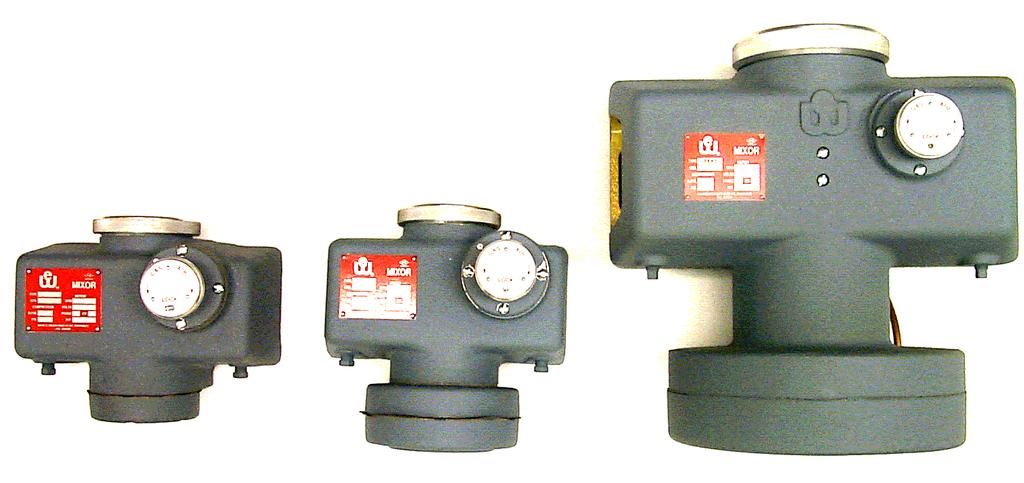
6 Waukee Carburetor Rev 4 Page 6 2. IMPORTANT SAFETY INFORMATION Waukee Engineering Company, Inc. Carburetors are not warranted or specified to meet the building or gas handling codes of any specific jurisdiction. In particular, certain codes state that gas handling equipment in certain applications must be leak tight. Waukee Engineering equipment does not meet the definition of leak tight. Similarly, Waukee Engineering equipment does not meet the requirements of codes which require hermetically sealed carburetors for certain applications. It is the responsibility of purchasers of Waukee Engineering equipment to determine the suitability of our equipment for a particular use and to determine the requirements of any codes which apply to the customer s proposed application. Waukee Engineering cannot be responsible for any accidents which occur from not-specifying Waukee Engineering equipment. Waukee Engineering Carburetors are designed solely for industrial applications installed in well ventilated, non-classified locations only. The equipment should not be installed or used in residential, institutional, office or other non-industrial, commercial applications. Failure to properly specify, install and ventilate Waukee Engineering equipment can result in serious accidents causing injury and even death. 3. DESCRIPTION Waukee Carburetors are designed to be easy to maintain and service so that down time is kept to a minimum. These units have a simple, compact design with minimal moving parts and are available in a wide range of sizes with capacities from 200 CFH to 12,000 CFH. Waukee Carburetors are designed specifically for high-precision mixing. Backlash has been reduced so that a given increment of change in the known ratio setting will produce the same increment of change in both the gas and air flows over the entire range of the unit. This is achieved without the use of gears, worms, or other complex devices. Time is saved because the operator can be sure of getting the exact ratio desired. Waukee Flo-Meters (not included) can be used in conjunction with the carburetor to provide a means of monitoring both air and gas so the ratio can be checked at any time.

7 Waukee Carburetor Rev 4 Page 7 4. PRINCIPLE OF OPERATION
8 Waukee Carburetor Rev 4 Page 8 5. SPECIFICATIONS Carburetor All Sizes Ratio Range: 1:1 to 40:1 Air to Gas Ratio Turn down: 3:1 Type 200 thru 750 (Carb 1) Inlet/Outlet Connections: ¾ NPT Capacity: CFH ( M3H) Type 1000 thru 2500 (Carb 2) Inlet/Outlet Connections: 1-¼"NPT Capacity: 1,000 2,500 CFH ( M3H) Type 3000 thru 8000 (Carb 3) Inlet/Outlet Connections: 2 NPT Capacity: 3,000 8,000 CFH ( M3H) Type 8000 thru (Carb 5) Inlet/Outlet Connections: 2 NPT Capacity: 8,000 10,000 CFH ( M3H) Gas Balancing Regulator Type 3xx Max Inlet Pressure: 2.0 PSIG (13.8 kpa) Max Gas Flow: Natural Gas 650 CFH (18.4 M3H) / Propane 410 CFH (11.6 M3H) Type 4xx Max Inlet Pressure: 2.0 PSIG (13.8 kpa) Max Gas Flow: Natural Gas 1,290 CFH (36.5 M3H) / Propane 820 CFH (23.2 M3H) Type 5xx Max inlet Pressure: 2.0 PSIG (13.8 kpa) Max Gas Flow: Natural Gas 2,580CFH (73 M3H) / Propane 1,640 CFH (46.4 M3H) Type 6xx Max Inlet Pressure: 2.0 PSIG (13.8 kpa) Max Gas Flow: Natural Gas 4,520CFH (128M3H) / Propane 2,860 CFH (81 M3H)
9 Waukee Carburetor Rev 4 Page 9 6. INSTALLATION 6.1 Mounting The carburetor can be mounted to a panel if needed, for panel mounting dimensions refer to dimension drawings located in Appendix A. The carburetor must be mounted vertical for proper operation. 6.2 Plumbing Guidelines Your company may have guidelines for plumbing installation. If so, you should check those before you begin the installation. As a guideline all plumbing recommendations and requirements in this manual are for reference only. The diagrams show important and recommended plumbing of the gas supply to the carburetor. Not all components shown in these drawing are included with Waukee s Carburetor. The customer is responsible for purchasing any recommended components and any additional safety equipment required by their company or equipment manufacture to meet any and all applicable national or local codes. 6.3 Plumbing When looking at the back of the carburetor the gas inlet is located on the right side, the air inlet is located on the left side and the mixed gas outlet is located in the center. See Figure 1. The Air inlet should have a filter installed to minimize the amount of dirt that enters the carburetor. The filter will improve performance and extend the time between maintenance intervals. The gas inlet should be connected to a gas balancing regulator referenced to the air inlet pressure. Use threading compound sparingly as any excess may enter the carburetor and affect its performance. Figure Recommended Plumbing Waukee recommends piping the Carburetor as shown in Figure 2. The Flo-Meters shown are not required, but provide visual indication of the actual flow rates for easy verification of ratio. The recommended plumbing does not show any safety devices that may be required, it is the customer s responsibility to install any safety devices that are required by the equipment manufacture or specified by their company. WARNING: Your equipment may require additional safety components; it is the customer s responsibility to install any additional components required for safety. Consult with the equipment manufacturer CAUTION as well as conforming to any guidelines specified by your company or governing agencies.
10 Waukee Carburetor Rev 4 Page 10 Figure 2 7. FIRST TIME STARTUP AND OPERATION Before starting up the equipment you should adjust the ratio of the carburetor with the control knob to a ratio close to what you plan to run at. To do this turn the control knob to the desired dial indicator setting, (Refer to Figure 3) turning the control knob clockwise will add more air and the dial indicator will decrease (Refer to Figure 4). Turning the control knob counterclockwise will add more gas and the dial indicator will increase. The numbers on the dial indicator are for reference only and do not indicate ratio. Table 1 shows some typical ratios and the number to set the dial indicator to achieve that ratio. Once you dial in the ratio you can start-up you equipment and make any final adjustments if needed. If desired you can lock the control knob in place with the lock screw. (See Figure 3) Ratio Dial Indicato r 2.5: : :1 4 10:1 3 Figure 3 Figure 4 Table 1
11 Waukee Carburetor Rev 4 Page MAINTENANCE 8.1 Carburetor In order to maintain the precision of your Waukee Carburetor, it is suggested that it be cleaned at least once a Month. The Waukee Carburetor has been designed to perform this maintenance with ease. This maintenance can be performed in minimal time since no special tools are required. The only tool needed is a screwdriver. Refer to Figure 3. CAUTION CAUTION: Before performing any maintenance, make sure all supply gases to the carburetor and compressor are Shut-Off Failure to Shut-Off the supply gas may expose flammable gases that may be ignited by open flames. To clean the carburetor, unscrew the top closure ring (29) by hand and carefully remove the sight glass dial indicator (30) and gasket (31). Next, unscrew the piston nut (27) by hand or carefully with screw driver. Pull the piston (26) out of the carburetor. The piston nut is fastened to the piston and will not fall in the carburetor. Next, by hand, pull the upper sleeve (23) bronze bushing out of the carburetor. Clean thoroughly with a solvent or good metal polish. Clean the piston in a similar manner. The segment (22) and lower guide (53) are not removable and must be cleaned in place with a rag soaked in solvent. After all parts have been thoroughly cleaned and dried, reassemble in this manner: With the slot in the upper sleeve (23) lined up with the adjustment screw plunger (8), lower the upper sleeve into the carburetor until it rests on the plunger. Next, push the plunger away from the sleeve by hand until the sleeve drops to a seated position. If alignment was correct, the slot in the upper sleeve will engage with the plunger. If not, rotate the upper sleeve until the plunger drops into the slot. Then replace the piston (23) and secure the piston nut (27) into place (Caution: Do not over tighten). Next, replace the sight glass dial indicator (30) which, if the assembly of the upper sleeve has been made correctly, will be flush with the top of carburetor. If the dial is flush, proceed with assembly as follows: gasket (31) above dial sight glass (30) and finally, top closure ring. The micrometer adjusting screw (1 thru 18) is a self-contained mechanism held in place on the front of the carburetor by four screws. It should be removed once a year or so depending on the cleanliness of the air drawn into the carburetor. To service, remove the four screws(12); pull unit out; wash in solvent; oil and reassemble components; inspect the condition of the gasket and install into the carburetor. Check to see that the adjustment screw plunger is engaged into the slot in the upper sleeve (23). If it is noticed through the sight glass that the piston does not move up and down as the flow is increased or decreased when the piston and other parts are clean, the cause of this is due to either a bad diaphragm or plugged vent holes. These parts can be serviced as follow: To remove the carburetor diaphragm (41), remove the top closure ring (29), sight glass (30), gasket (31), dial (28) and piston (26). Turn the carburetor upside down and remove bottom flange (44) which is held in place by six or eight screws (45). Remove diaphragm and piston rod assembly (39 thru 43). Clean carburetor body and all other parts. Pass wire through vent tube in carburetor body and vent hole in diaphragm flange. Remove defective diaphragm from piston rod and replace with a new one. Refer to Diaphragm assembly on page 10. Care must be exercised in positioning the new diaphragm on the piston rod so that the rod does not bind when it passes through the square hole in the lower guide. If position is correct, then the vent tube hole in the diaphragm will move an equal distance to the right or left of the vent tube. When properly located, replace bottom flange and turn carburetor
12 Waukee Carburetor Rev 4 Page 12 right side up. If assembly has been made correctly and by-pass holes are clean, a slight hissing of air can be heard when piston rod is moved up or down. Continue assembly of piston and other parts as explained below.
13 Waukee Carburetor Rev 4 Page Diaphragm Assembly To assemble piston shaft (39), assemble in the following sequence: 1. diaphragm thrust washer (40) 2. diaphragm pan (48) 3. diaphragm (41) 4. diaphragm pan (48) 5. diaphragm lock washer (42) 6. diaphragm nut (43) To finish the assembly insert the diaphragm piston shaft assembly into the carburetor, insert the locating pin. Then line up the bottom flange (44) with the locating pin and securely fasten bottom flange with flange screws (45). 8.3 Gas Balancing Regulator The purpose of the gas balancing regulator is to maintain the proper gas and air pressure across the parts of the carburetor at varying flows or outputs of the mixing equipment. Your Waukee Carburetor has been completely tested at the factory and has been set up to give the best results for ratio control throughout the range specified at the time of order and will not require resetting except in unusual cases. The following procedure is used if you should want to determine if the balancing regulator is functioning properly. First, check the incoming gas pressure. If gas pressure is constant within the range of 4 to 8 W.C., then check the air filter and Flo-Meters to see if they are clean. Remove the 1/8 pipe plugs on the bottom of the carburetor. Insert 1/8 pipe nipples or 1/8 pet cock. Connect a water manometer across these two points with rubber tubing. Close the valve between the outlet side of the compressor and the unit being served. Open the gas valve on the gas line. Start the compressor. Now open the outlet valve to the flow desired as indicated on the Flo- Meters. Adjust the ratio to that desired by turning the micrometer adjusting knob on the carburetor to the direction indicated on the knob for more gas or more air, whichever the case may be. Now observe the reading on the manometer. If the reading is not within the differential (total distance from top and bottom of water level in manometer) adjust by removing the cap on the balancing regulator and screwing the adjustment nuts clockwise or counter-clockwise as the case may be. Make a slight adjustment first and then replace the cap tightly on the regulator, as THE CAP MUST BE SEALED TO OBTAIN AN ACCURATE READING. Repeat removing the cap and adjusting and replacing the cap before taking a reading until the manometer reads the same as the factory setting. Check several different flows at the ratio you desire to operate. Do not attempt to run at flows lower than ¼ output. Look into the observation window on carburetor to see if the piston moves up and down when unit is changed from low flow to maximum output. If not, refer to maintenance and trouble shooting. Good ratio control cannot be obtained unless all parts such as Flo-Meters, carburetor piston and unloader piston are clean and in good working order. If it is still impossible to balance the differential for good ratio control, then the chances are that one of the two diaphragms in the regulator is leaking. Replace with a new regulator.
14 Waukee Carburetor Rev 4 Page TROUBLESHOOTING PROBLEM SYMPTOMS RECOMMENDED ACTION Failure to maintain Insufficient or varying Check and regulate pressures upstream of the carburetor. constant ratio gas pressure Dirty carburetor Clean as outlined under MAINTENANCE OF THE CARBURETOR. Check and replace diaphragm as necessary. Dirty air filter or Flo- Meter Differential across carburetor out of adjustment Clean or replace as necessary. Adjust as outlined under MAINTENANCE OF THE GAS BALANCING REGULATOR. Check and replace diaphragm as necessary.
15 Waukee Carburetor Rev 4 Page APPENDIX A DRAWINGS On Demand
16 Waukee Carburetor Rev 4 Page APPENDIX B PARTS LIST ITEM CFH PART # CFH PART # CFH PART # REQUIRED DESCRIPTION Take-Up Nut Control Knob Lock Screw Adjustment Housing Locating Pin Take-Up Nut Lock Screw Adjustment Housing Adjustment Nut Stop Screw Adjustment Screw Thrust Washer Adjustment Plunger Arm Plunger Arm Cotter Pin Ratio Setting Lock Screw Control Knob Adjustment Housing Screw Take-Up Nut Thrust Washer Adjustment Screw O Ring Adjustment Screw Adjustment Nut Adjustment Plunger Arm Spring Adjustment Housing Gasket Nameplate Screw Nameplate Main Body Segment Upper Sleeve Dial & Sight Glass Locating Pins Piston Nut Retaining Rings Piston Piston Nut Dial Indicator Top Closure Ring Sight Glass Top Closure Ring Gasket Segment Screw N/A Outlet Flange Locating Pin (Obsolete) Outlet Flange Gasket Outlet Flange N/A Pipe Plug (Obsolete) N/A Outlet Flange Screw (Obsolete) Diaphragm Gaskets Piston shaft Diaphragm Thrust Washer Diaphragm Diaphragm Lock washer Diaphragm Nut Bottom Flange or 8 Bottom Flange Screws Orifice Locating Pin Diaphragm Pan Gaskets Diaphragm Pans Bottom Flange Adapter Bottom Flange Adapter Screws Orifice Locating Pin Bottom Flange Adapter Gasket Lower Guide N/A Lower Guide Screw (Obsolete) Inlet Flange (Not Shown) Inlet Flange Gasket (Not Shown)
17 Waukee Carburetor Rev 4 Page 17 Waukee Warranty Policy, Disclaimer and Limitation of Liability EXPRESS WARRANTY ON WAUKEE EQUIPMENT WAUKEE warrants its products for a period of one (1) year from date of shipment from WAUKEE to the original purchaser to be free from defects in material and workmanship under normal recommended use, service, inspection and maintenance. Normal recommended use, service inspection and maintenance mean: 1. Not to be used in excess of nor below the rated capacity, pressures and temperature ranges specified in the applicable quotation, purchase order, acknowledgment, marketing literature, nameplate(s), specification sheet or the Installation, Operation, Inspection and Maintenance Manual (THE MANUAL); 2. Using only clean liquids or gases (only liquids in liquid Flo-Meters and only gases in gas Flo-Meters); air and fuel gases used in mixing equipment to be clean and free of solids all as further explained in THE MANUAL; and 3. Installation, operation, inspection and maintenance in compliance with THE MANUAL; and 4. The WAUKEE products being used only in: a) Ambient environments lower than 132 Fahrenheit (54 Celsius) unless specifically designed and so labeled by WAUKEE for higher temperatures; and b) Non-corrosive environments; and c) Completely protected from moisture, rain, snow or other outside environments; and d) Not to be used below 32 Fahrenheit (0 Celsius) unless special precautions are taken for low temperature conditions as shown in THE MANUAL 5. Being used only for applications permitted by THE MANUAL or other WAUKEE literature or special applications approved in a separate written authorization by WAUKEE WARRANTY EXCEPTIONS This Warranty does not apply to damage caused by any or all of the following circumstances or conditions: 1. Freight damage; 2. Parts, accessories, materials or components not obtained from nor approved in writing by WAUKEE; 3. Any consequential or incidental damages including but not limited to loss of use, loss of profits, loss of sales, increased costs, arising from the use of any product, system or other goods or services manufactured, sold or provided by WAUKEE; 4. Misapplication, misuse and failure to follow THE MANUAL or other literature, instructions or bulletins (including drawings) published or distributed prior to THE MANUAL The exclusive remedy under this Warranty or any other express warranty is the repair or replacement without charge for labor and materials of any WAUKEE parts found upon examination by WAUKEE to have been defective. Since certain WAUKEE equipment is heavy, bulky and not deliverable by U.S. mail or other parcel
18 Waukee Carburetor Rev 4 Page 18 service, WAUKEE equipment may be returned only upon written consent of WAUKEE and then only to the location designated by WAUKEE. Generally such consent will be given only upon the condition that the customer assume and prepay all carrier charges and responsibility for damage in transit. Purchasers of WAUKEE products, equipment, goods or services waive subrogation on all items covered under their own or any other insurance. DISCLAIMER THIS WARRANTY IS EXCLUSIVE. WAUKEE EXPRESSLY DISCLAIMS ANY AND ALL OTHER WARRANTIES WHETHER EXPRESS OR IMPLIED INCLUDING ANY IMPLIED WARRANTY OF MERCHANTABILITY OR FITNESS FOR A PARTICULAR PURPOSE OR ANY PURPOSE. No person, including any dealer, seller or other representative of WAUKEE is authorized to make, on behalf of WAUKEE, any representations beyond those contained in WAUKEE literature and documents or to assume for WAUKEE any obligations or duties not contained in this Warranty and Warranty Policy. WAUKEE reserves the right to make design and other changes, modifications or improvements to its products, services, literature or systems, without any obligation, to furnish or install same on any previously sold or delivered products or systems. LIMITATION OF LIABILITY It is expressly agreed that the liability of WAUKEE is limited and WAUKEE does not function as an insurer. The purchaser and/or user agree that WAUKEE is not liable for loss, harm or damage due directly or indirectly to any occurrence or consequences there from. If WAUKEE should be found liable to anyone on any theory (except any express warranty where the remedy is set forth in Section 2 of this Warranty and Warranty Policy) for loss, harm or damage, the liability of WAUKEE shall be limited to the lesser of the actual loss, harm or damage or the purchase price of the involved WAUKEE equipment or service when sold (or when service performed) by WAUKEE to its customer. This liability is exclusive and regardless of cause or origin resulting directly or indirectly to any person or property from: 1. The performance or nonperformance of any obligations set forth in this Warranty and Warranty Policy: 2. 2 Any agreement including specifications between WAUKEE and the customer; 3. 3 Negligence, active, passive or otherwise of WAUKEE or any of its agents or employees; 4. Breach of any judicially imposed warranty or covenant of workmanship, durability or performance; and 5. Misrepresentation (under the Restatement, common law or otherwise) and/or strict liability involvement 6. Liability for fraud-in-the-inducement INFORMATION NECESSARY TO OBTAIN TECHNICAL ASSISTANCE For WAUKEE to appropriately respond to a request for assistance or evaluation of customer or user operating difficulty please provide at a minimum the following information: 1. Serial number and type or model of meter, compressor or other equipment and all other data shown on the nameplate and on the specific component which appears to be involved in the difficulty; 2. The date and from whom you purchased your WAUKEE equipment and your purchase order number
19 Waukee Carburetor Rev 4 Page State your difficulty, being sure to mention at least the following: 4. Application 5. Input pressure where Flo-Meters or compressors are involved 6. Condition of filters, strainers or screens, upstream or downstream of the WAUKEE equipment 7. Gas or liquid temperatures and other ambient conditions at the time of the difficulty 8. Type of lubrication being used (if any) - give specifics 9. Any other relevant pressures including gauge readings both upstream and downstream of the WAUKEE equipment. 10. All electrical information available. 11. Performance activity. 12. Any other pertinent information. If a sketch would help explain the difficulty, please include one. WARRANTY FIELD SERVICE If warranty Field Service at the request of the purchaser or user is rendered and the difficulty is found not to be with WAUKEE's product, the purchaser shall pay the time and expense (at the prevailing rate at the time of the service) of WAUKEE's field representative(s). Charges for service, labor and other expenses that have been incurred by the purchaser, its customer or agent without written approval of WAUKEE will not be accepted. The OEM or other reseller is responsible for transmitting installation and operating instructions, THE MANUAL or other service literature supplied by WAUKEE with the equipment


20 Waukee Carburetor Rev 4 Page 20 Reach us at United Process Controls brings together leading brands to the heat treating industry including Waukee Engineering, Furnace Control, Marathon Monitors and Process-Electronic. We provide prime control solutions through our worldwide sales and services network with easy-toaccess local support. UNITED PROCESS CONTROLS INC. WAUKEE PRODUCTS PLANT 5600 West Florist Avenue, Milwaukee, WI 53218, U.S.A. Phone: Fax: waukee.sales@group-upc.com
Waukee AutoLube User Manual
 Waukee AutoLube User Manual Manual #: 016 Initial Release {4/24/2008} Rev No: C Date: 12/22/10 For assistance please contact: Waukee Engineering Co. Inc. TEL: +1-414-462-8200 FAX: +1-414-462-7022 sales@waukeemeters.com
WAUKEE ENGINEERING Ratio Control Valve Installation And Operation Manual
 WAUKEE ENGINEERING Ratio Control Valve Installation And Operation Manual NOTICE This manual contains important safety information and should be read and understood by all installation personnel and all
INSTALLATION, INSTRUCTION AND SERVICE MANUAL
 INSTALLATION, INSTRUCTION AND SERVICE MANUAL Actuator/Brake/Trailer Dealer Please provide to consumer. Consumer Read and follow instructions. Keep with trailer for reference. Page 1 of 7 1. Introduction...
PREMIER, MARINE, & STANDARD
 INSTA LLATION INSTRUCTION AND SERVICE MANUAL I TITAN 12" x 2" BRAKES FREE BACKING. UNI-SERVO. DUO-SERVO PREMIER, MARINE, & STANDARD Limited Warranty TITAN Inc. ("TITAN') warrants its products to be free
TITAN 13 x 2½ BRAKES DUO-SERVO AND FREE BACKING
 INSTALLATION INSTRUCTION AND SERVICE MANUAL Actuator/Trailer Dealer - Please provide these instructions to the consumer. Consumer - Read and follow these instructions. Keep them with the trailer for future
TBM Series 3-Way Ball Valve
 www.simtechusa.com TBM Series 3-Way Ball Valve Operating, Installation, & Maintenance Manual Corrosion Resistant Fluid and Air Handling Systems. Dated 06-26-13 TBM Series Ball Valves SIMTECHRECOMMENDSREADINGTHEFOLLOWINGINFORMATIONPRIORTOINSTALLINGANDUSING
INSTALLATION INSTRUCTIONS
 INSTALLATION INSTRUCTION AND SERVICE MANUAL Actuator/Trailer Dealer - Please provide these instructions to the consumer. Consumer - Read and follow these instructions. Keep them with the trailer for future
Lubricator Gun: 10,000 psi (700 bar) Maximum Delivery Pressure when disconnected from Dispenser
 Maximum Delivery Pressure when disconnected from Dispenser") INSTRUCTIONS-PARTS LIST 30 455 INSTRUCTIONS This manual contains important warnings and information. READ AND KEEP FOR REFERENCE. Rev. C Supercedes B Hand-Operated Portable Grease Dispenser Buckshot Luber
INSTRUCTIONS-PARTS LIST 30 455 INSTRUCTIONS This manual contains important warnings and information. READ AND KEEP FOR REFERENCE. Rev. C Supercedes B Hand-Operated Portable Grease Dispenser Buckshot Luber
WAUKEE ENGINEERING Valve-Tronic 3.5 Installation And Operation Manual
 WAUKEE ENGINEERING Valve-Tronic 3.5 Installation And Operation Manual NOTICE This manual contains important safety information and should be read and understood by all installation personnel and all users
APCO ASR-400/450 SEWAGE AIR RELEASE VALVES
 APCO ASR-400/450 SEWAGE AIR RELEASE VALVES Instruction D12005 December 2012 Instructions These instructions provide installation, operation and maintenance information for the APCO ASR- 400/450 Sewage
Fifth Wheel Power Hitch Operations Manual
 Fifth Wheel Power Hitch Operations Manual ITD1253 Fifth Wheel Power Hitch 208 587 7960 www.intheditch.com This page is intentionally left blank. Operations Manual 1 TABLE OF CONTENTS TABLE OF CONTENTS...
Operating Instructions and Parts Manual Long Chassis Service Jacks
 Operating Instructions and Parts Manual Long Chassis Service Jacks Models JSJ-3T/JSJ-5T/JSJ-10T WMH TOOL GROUP 2420 Vantage Drive Elgin, Illinois 60123 Part No. M-454430 Ph.: 800-274-6848 Revision A 8/05
PENBERTHY MODELS GL AND GH GAS OPERATED JET PUMPS INSTALLATION, OPERATION AND MAINTENANCE INSTRUCTIONS
 Before installation, these instructions must be read carefully and understood. PRODUCT WARRANTY Emerson warrants its Penberthy products as designed and manufactured to be free of defects in the material
DeZURIK AFR3 Filter Regulator Used on Pneumatic Cylinder Actuators
 AFR3 Filter Regulator Used on Pneumatic Cylinder Actuators Instructions D11033 August 2013 Instructions These instructions provide information about AFR3 Filter Regulators. They are for use by personnel
ORIGINAL INSTRUCTIONS G715A. Pneumatic-hydraulic Riveter E. Warner Ave Santa Ana, CA
 ORIGINAL INSTRUCTIONS G715A Pneumatic-hydraulic Riveter 1224 E. Warner Ave Santa Ana, CA 92705 www.cherryaerospace.com DESCRIPTION The Cherry G715A Pneumatic-Hydraulic Riveter is designed specifically
TERMS OF USE TERMS AND CONDITIONS. Plumbing and Heating Products (PL-WR)
") TERMS OF USE 1. Watts pricing and product data is subject to change without notice and such changes supersede all previous versions. 2. Watts data is to be used as provided. Watts is not responsible for
TERMS OF USE 1. Watts pricing and product data is subject to change without notice and such changes supersede all previous versions. 2. Watts data is to be used as provided. Watts is not responsible for
Colt Series C400, C500
 Colt Series C400, C500 RP/IS-A-C400/C500 C400 OSY Reduced Pressure Zone Assemblies Reduced Pressure Detector Assemblies Sizes: 2 1 2" 10" (65 250mm) Installation Service Repair Kits Maintenance For other
Nor East. Instructions Safety Messages. Inspection. Parts. DeZURIK Service. Type 05 Pneumatic Actuator Used With Globe Valves
 Instructions Safety Messages These instructions are intended for personnel who are responsible for installation, operation and maintenance of your DeZURIK Actuator. All safety messages in the instructions
Service Guide JATCO Environmental Protection Tank Model J-7000
 Service Guide JATCO Environmental Protection Tank Model J-7000 Listed below are a series of steps to follow if the JATCO tank fails to dump properly. #1. Be sure there is an adequate supply of gas pressure
PRODUCT SERVICE MANUAL FOR BK12DHZ PUMPS
 PRODUCT SERVICE MANUAL FOR BK12DHZ PUMPS WARNING This manual, and the GENERAL INSTRUCTION MANUAL SRM00046, should be read thoroughly prior to pump installation, operation or maintenance. Manual No. SRM00095
Nor East. Instructions. Safety Messages. Inspection. Parts Nor East Controls. Service. Type 05 Air-O-Motor Actuator Used With Globe Valves
 Instructions Safety Messages These instructions are intended for personnel who are responsible for installation, operation and maintenance of your Nor East Controls Actuator. All safety messages in the
7.3L POWERSTROKE BANJO BOLT KIT Fits L Powerstroke Diesel. Installation Guide
 7.3L POWERSTROKE BANJO BOLT KIT Fits 94-03 7.3L Powerstroke Diesel Installation Guide INSPECT CONTENTS OF THIS KIT THOROUGHLY BEFORE STARTING THE INSTALLATION PROCESS! IF YOU FIND A PROBLEM WITH YOUR PACKAGE:
Dual Phase Extraction Inlet. Patent No Installation Manual. P/N Rev
 Patent No. 6520259 Installation Manual P/N 95232 Rev 6-16-11 Table of Contents ing Extraction Inlets track changing water levels to maintain optimum performance 1.Component Identification Page 1 2. How
HYDRAULIC POWER PACK
 HYDRAULIC POWER PACK OPERATION & MAINTENANCE MANUAL Model 34484 Copyright 2012 by All rights reserved. No part of this publication may be copied, reproduced or transmitted in any form whatsoever without
DeZURIK 2 20" BOS BUTTERFLY VALVES
 2 20" BOS BUTTERFLY VALVES Instruction D10459 October 2013 2-20 BOS Butterfly Valves Instructions These instructions provide information about BOS Butterfly Valves. They are for use by personnel who are
OWNER S MANUAL. WARNINGS and PRECAUTIONS WARNINGS AND PRECAUTIONS. automatic positive locking traction differential
 77401-detroit E-Z locker 1/25/02 11:01 AM Page 1! WARNINGS and PRECAUTIONS OPERATOR: Use extreme caution when accelerating or decelerating on slippery or unstable surfaces. Vehicles/axles equipped with
ORIGINAL INSTRUCTIONS G700
 ORIGINAL INSTRUCTIONS G700 HYDRO-SHIFT CHERRYLOCK RIVETER 1224 East Warner Ave, Santa Ana, Ca 92705 Tel: 1-714-545-5511 Fax: 1-714-850-6093 www.cherryaerospace.com G700 HYDRO-SHIFT INSTRUCTIONS TABLE OF
Series 957, 957N, 957Z, 957RPDA, 957NRPDA, 957ZRPDA
 Series 957, 957N, 957Z, 957RPDA, 957NRPDA, 957ZRPDA Reduced Pressure Zone Assemblies Reduced Pressure Detector Assemblies Sizes: 2 1 2" 10" (65 250mm) Installation Service Repair Kits Maintenance RP/IS-957/957RPDA
PPM EO-100 TM. Operation Manual
 PPM EO-100 TM Open Loop Electric Prewet Power Module Operation Manual Rev A Page 1 2/23/2010 Copyright 2008 by Cirus Controls, LLC. All Rights Reserved. No part of this material may be reproduced in any
APCO CRF-100A RUBBER FLAPPER SWING CHECK VALVES
 APCO CRF-100A RUBBER FLAPPER SWING CHECK VALVES Instruction D12043 June 2016 DeZURIK Instructions These instructions provide installation, operation and maintenance information for APCO CRF-100A Rubber
Model , Series A 9 in. (23 cm) roller frame with 45 angle and 12 in. reach 1/2 in. (13 mm) nap roller cover
 roller frame with 45 angle and 12 in. reach 1/2 in. (13 mm) nap roller cover") Operating Instructions 309899 Rev. A This manual contains important warnings and information. READ AND KEEP FOR REFERENCE. INSTRUCTIONS Manufactured by Model 246818, Series A 9 in. (23 cm) roller frame
Operating Instructions 309899 Rev. A This manual contains important warnings and information. READ AND KEEP FOR REFERENCE. INSTRUCTIONS Manufactured by Model 246818, Series A 9 in. (23 cm) roller frame
Warranty Information North America
 Publication No. 47705137 January 1, 2014 Warranty Information North America Industrial and Power Generation Power Systems Parts and Accessories Includes: Power Systems Warranty Statement Parts and Accessories
Dual/Triple Manifold Water Filtration Systems Instruction Manual
 3M TM Water Filtration Products Dual/Triple Manifold Water Filtration Systems Instruction Manual High Flow Series Water Filtration Systems Installer: Please leave this manual with owner/operator. 3M Water
Tri-Clover Manual and Air Actuated Fractional Valves
 FVSM-99 Tri-Clover Manual and Air Actuated Fractional Valves Series 650 655 660 CONTENTS Thank you for purchasing an Alfa Laval Product! This manual contains disassembly and assembly instructions, maintenance
24G621 Agitator Speed Controller Accessory
 Instructions-Parts 24G62 Agitator Speed Controller Accessory 3A35A ENG Accessory kit to control and automatically maintain the speed of an air-powered agitator. For professional use only. Important Safety
LUBRICATOR GUN INSTRUCTIONS-PARTS LIST. 10,000 psi (700 bar) Maximum Delivery Pressure. Detachable-type
 Maximum Delivery Pressure. Detachable-type") INSTRUCTIONS-PARTS LIST 306 460 INSTRUCTIONS This manual contains important warnings and information. READ AND KEEP FOR REFERENCE. Rev. E Supercedes D Detachable-type LUBRICATOR GUN 10,000 psi (700 bar)
INSTRUCTIONS-PARTS LIST 306 460 INSTRUCTIONS This manual contains important warnings and information. READ AND KEEP FOR REFERENCE. Rev. E Supercedes D Detachable-type LUBRICATOR GUN 10,000 psi (700 bar)
Installation Instructions and Service Manual
 Installation Instructions and Service Manual Model 66 Actuator* for Trailer Brakes 6600 lbs Capacity Part #47210/86167 - Drum Brake Ready Part #47211/86165 - Disc Brake Ready *US Patent No. 6,375,211 MODEL
INTRODUCTION INSTALLATION
 INTRODUCTION INSTALLATION, OPERATION & MAINTENANCE INSTRUCTIONS This instruction manual includes installation, operation and maintenance information for the figure G73 gear operator. The figure G73 is
Model 80 & 80E Actuator* for Trailer Brakes 8000 lbs Capacity Part #47206/ Drum Brake Ready Part #47208/ Disc Brake Ready
 Installation Instructions and Service Manual For Serial Numbers 6020 and above. Model 80 & 80E Actuator* for Trailer Brakes 8000 lbs Capacity Part #47206/47207 - Drum Brake Ready Part #47208/47209 - Disc
Installation Instructions and Service Manual
 Installation Instructions and Service Manual Model 80 Actuator* for Trailer Brakes 8,00 lbs Capacity Drum Brake Ready Disc Brake Ready US Patents: 6,37,2 and 8,342,9 *Model 80 - Manufactured after March
READ THIS MANUAL CAREFULLY BEFORE USING THE PUMP
 OWNER S MANUAL Pond Pump READ THIS MANUAL CAREFULLY BEFORE USING THE PUMP Important Notice: This manual contains important information about the installation, operation and safe use of this product. This
DAP-625S and DAP-875S
 AIR CHAMP PRODUCTS DAP-625S and DAP-875S (i) FORM NO. L-20078-B-0501 In accordance with Nexen s established policy of constant product improvement, the specifications contained in this manual are subject
END USER TERMS OF USE
 END USER TERMS OF USE The following is the End Users Terms of Use as it currently appears in the Mobileye User Manual and Warranty information. This is here for your review and information; it is subject
Pump/Manifold Kits. Instructions F ENG. To convert E-Flo 4-Ball Piston Pumps to a different size lower. For professional use only.
 Instructions Pump/Manifold Kits 311611F ENG To convert E-Flo 4-Ball Piston Pumps to a different size lower. For professional use only. See page 2 for a list of available kits. Important Safety Instructions
Scale Feeder Manifold Water Filtration System Instruction Manual
 3M TM Water Filtration Products Scale Feeder Manifold Water Filtration System Instruction Manual For SF1XX High Flow Series Water Filtration Systems Installer: Please leave this manual with owner/operator.
Air Lift. Kit PERFORMANCE INSTALLATION GUIDE Scion xb
 Air Lift PERFORMANCE Kit 75699 2008- Scion xb MN-689 (041108) ECR 7072 INSTALLATION GUIDE For maximum effectiveness and safety, please read these instructions completely before proceeding with installation.
Model 66/660* Actuator for Trailer Brakes 6,600 lbs Capacity Drum Brake Ready or Disc Brake Ready US Patent No. 6,375,211
 Installation Instructions and Service Manual Model 66/660* Actuator for Trailer Brakes 6,600 lbs Capacity Drum Brake Ready or Disc Brake Ready US Patent No. 6,375,211 *Model 660 - Manufactured after March
PRODUCT SERVICE MANUAL. BK6DHZ(C)-250, 275, 312 and 400 PUMPS
-250, 275, 312 and 400 PUMPS") PRODUCT SERVICE MANUAL BK6DHZ(C)-250, 275, 312 and 400 PUMPS WARNING This manual, and the GENERAL INSTRUCTION MANUAL, SRM00046, should be read thoroughly prior to pump installation, operation or maintenance.
PRODUCT SERVICE MANUAL BK6DHZ(C)-250, 275, 312 and 400 PUMPS WARNING This manual, and the GENERAL INSTRUCTION MANUAL, SRM00046, should be read thoroughly prior to pump installation, operation or maintenance.
Users Guide for Ac-sync
 Problem solved. Users Guide for Ac-sync Thank you for choosing Anywhere Cart! The AC-SYNC is designed to sync, charge and store 1-36 ipads or tablets. Adjustable device divider bays allow fitment of any
INSTRUCTIONS SMOKE BLOWER WITH HONDA ENGINE PART NUMBER
 1 INSTRUCTIONS SMOKE BLOWER WITH HONDA ENGINE PART NUMBER 303-568 CHERNE INDUSTRIES INCORPORATED 1-800-THE PLUG 5700 LINCOLN DRIVE (1-800-843-7584) MINNEAPOLIS, MN 55436-1695 FAX: 1-800-843-7585 www.cherneind.com
Pressurized oil drain for collection of used lubricants and anti-freeze.
 Instructions - Parts List 24-Gallon (90-Liter) Oil Ace 30864B Pressurized oil drain for collection of used lubricants and anti-freeze. Model 9577 Series A 8 psi (55 kpa,5 bar) Maximum Working Pressure
37SCENE 46SCENE 79SCENE
 Installation and Operation Instructions LED SCENE LIGHT LED SCENE LIGHT 37SCENE 46SCENE 79SCENE 37SCENE 46SCENE Introduction The 37SCENE, 46SCENE, 79SCENE LED Scene Lights are designed for the emergency
HR-20P Pneumatically Controlled Pressure Regulator
 HR-20P Pneumatically Controlled Pressure Regulator Instruction and Service Manual Hydroplex Corporation 230 West Gloria Switch Rd. Lafayette, LA 70507 337-233-0626 www.hydroplexpumps.com I. General Instructions
NECO Pumping Systems
 INSTALLATION OPERATION & MAINTENANCE INSTRUCTIONS For Your NECO Pumping Systems PACKAGED CIRCULATING SYSTEM THIS COMPLETELY ASSEMBLED, TESTED, PACKAGED CIRCULATING SYSTEM IS OF THE HIGHEST QUALITY AND
300 Series INSTRUCTION MANUAL. Compressed Air Filters Models 302 (grade) through 317 (grade)
 through 317 (grade)") INSTRUCTION MANUAL 300 Series Compressed Air Filters Models 302 (grade) through 317 (grade) FORM NO.: 3259480 REVISION: 01/2014 READ AND UNDERSTAND THIS MANUAL PRIOR TO OPERATING OR SERVICING THIS PRODUCT.
INSTRUCTION MANUAL 300 Series Compressed Air Filters Models 302 (grade) through 317 (grade) FORM NO.: 3259480 REVISION: 01/2014 READ AND UNDERSTAND THIS MANUAL PRIOR TO OPERATING OR SERVICING THIS PRODUCT.
Installation Instructions and Service Manual
 Installation Instructions and Service Manual Model 700LP/750LP (Low Profile) Actuator* for Trailer Brakes 7,000/7,500 lbs. Capacity Drum Brake Ready/Disc Brake Ready *US Patent No. 6,375,211 MODEL 700LP/750LP
Single-Position Detent Clutch DC Series. (i) MTY (81) MEX (55) QRO (442)
 MTY (81) MEX (55) QRO (442)") Single-Position Detent Clutch DC Series (i) FORM NO. L-2017-A-001 In accordance with Nexen s established policy of constant product improvement, the specifications contained in this manual are subject
Single-Position Detent Clutch DC Series (i) FORM NO. L-2017-A-001 In accordance with Nexen s established policy of constant product improvement, the specifications contained in this manual are subject
Motor Mounting Kits. Instructions J EN. 16C487 Motor Coupler Kit includes 2.25 in. (57.2 mm) key For NEMA 182/184 TC Frame ATEX Electric Motors
 key For NEMA 182/184 TC Frame ATEX Electric Motors") Instructions Motor Mounting Kits 31160J EN To install electric motors on E-Flo 4-Ball Piston Pumps. For professional use only. (Kits do not include motors.) 16C487 Motor Coupler Kit includes 2.2 in. (7.2
Instructions Motor Mounting Kits 31160J EN To install electric motors on E-Flo 4-Ball Piston Pumps. For professional use only. (Kits do not include motors.) 16C487 Motor Coupler Kit includes 2.2 in. (7.2
INSTALLATION AND OPERATING MANUAL
 Publication T3-76, Rev. 1 Dated: May 9, 21 INSTALLATION AND OPERATING MANUAL MODEL: T3-I TURBOTWIN Engine Air Starter AN96-419 From Tech Development Inc 68 Poe Ave. Dayton OH 45414 Tel: (937) 898-96 Fax:
INSTALLATION AND OPERATING MANUAL
 Dated: May 10, 2001 INSTALLATION AND OPERATING MANUAL MODEL: T30-Y TURBOTWIN Engine Air Starter From Tech Development Inc AN96-425 6800 Poe Ave. Dayton OH 45414 Tel: (937) 898-9600 Fax: (937) 898-8431
900 SERIES SPLIT CASE FIRE PUMP REPAIR PARTS INDEX
 900 SERIES SPLIT CASE FIRE PUMP REPAIR PARTS INDEX Read and understand the pump and motor instructions before attempting to install, disassemble or repair the pump. Part # AF-03-326 2015 Pentair Ltd. 01/30/15
Installation, Maintenance, & Repair Series 995 Reduced Pressure Zone Backflow Preventers
 Installation, Maintenance, & Repair Series 995 Reduced Pressure Zone Backflow Preventers RP/IS-995 Sizes: 2" through 2" (5-50mm)! WARNING Read this Manual BEFORE using this equipment. Failure to read and
SUNTURA SOLAR TRACKER
 WindyNation SUNTURA SOLAR TRACKER SOT-TRKS-NF User s Manual Page 1 of 10 WindyNation 08/09/2012 Table of Contents 1 Introduction... 3 1.1 Limited Warranty... 3 1.2 Restrictions... 3 1.3 Warranty Claims
II DISTRIBUTION & SUBSTATION TYPE C
 CapCheckIII DISTRIBUTION & SUBSTATION TYPE Ca p a c i t o r C h e c ke r Operating & Instruction Manual 1475 Lakeside Drive Waukegan, Illinois 60085 U.S.A. 847.473.4980 f a x 8 4 7. 4 7 3. 4 9 8 1 w e
S h a f t S e a l INSTALLATION INSTRUCTIONS. For Shafts : 4 to 6 (100 to 150mm)
") S h a f t S e a l INSTALLATION INSTRUCTIONS For Shafts : 4 to 6 (100 to 150mm) IMPORTANT INSTRUCTIONS-READ BEFORE STARTING! IMPORTANT! - BEFORE STARTING YOUR INSTALLATION CAREFULLY READ THE FOLLOWING WARNINGS
S h a f t S e a l INSTALLATION INSTRUCTIONS For Shafts : 4 to 6 (100 to 150mm) IMPORTANT INSTRUCTIONS-READ BEFORE STARTING! IMPORTANT! - BEFORE STARTING YOUR INSTALLATION CAREFULLY READ THE FOLLOWING WARNINGS
4" ENVIRONMENTAL E-SERIES PUMPS OWNER'S MANUAL. DANGER warns about hazards that will cause. WARNING warns about hazards that can cause
 4" ENVIRONMENTAL E-SERIES PUMPS OWNER'S MANUAL BEFORE INSTALLING PUMP, BE SURE TO READ THIS OWNER S MANUAL CAREFULLY. CAUTION Fill pump with water before starting or pump will be damaged. The motor on
Universal Hand Pump. Instructions D EN. - For transferring grease to Grease Jockey and G3 Systems - Part No Hand Operated - 35# Pump
 Instructions Universal Hand Pump 31758D EN - For transferring grease to Grease Jockey and G3 Systems - Part No. 47886 Hand Operated - 35# Pump 600 psi (4.13 MPa, 41.3 bar) Maximum Working Pressure 85 ml
Full Length Bed Rail - Model G29
 User Manual DEALER: These instructions MUST be given to the user of the product. USER: BEFORE using this product, read this manual and save for future reference. 1 General Check all parts for shipping
Fifth Wheel Power Hitch ITD1253 OPERATIONS MANUAL
 Fifth Wheel Power Hitch ITD1253 OPERATIONS MANUAL TM 208-587-7960 www.intheditch.com For the most up to date information please visit our website at: www.intheditch.com Like us on Facebook www.facebook.com/intheditch
DODGE CUMMINS Air-Boss CR Intake Plenum
 Installation Manual P/N 0307-ABIP 2003-07 DODGE CUMMINS Air-Boss CR Intake Plenum Installation Instructions P/N 0307-ABIP GDP Air-Boss CR Plenum Installation PLEASE READ ALL INSTRUCTIONS BEFORE BEGINNING
FurnaceDoctor -DPT Dewpoint Analyzer. User Manual Version 008
 FurnaceDoctor -DPT Dewpoint Analyzer User Manual Version 008 Manual FurnaceDoctor -DPT - Version 8 Page 2 of 13 Manual #: 003 Rev No: 8 COPYRIGHT (C) No part of this publication may be reproduced, transmitted,
SUPER PUMP OUT SYSTEM
 Congratulations on your purchase of the SUPER PUMP OUT SYSTEM. This instruction/parts manual is a guide for operating and servicing your BLUELINE SUPER PUMP OUT SYSTEM. Proper operation and service are
Preassembled Clutch/Brake Module
 Preassembled Clutch/Brake Module P-273-1-WE 819-0343 Installation Instructions An Altra Industrial Motion Company Contents MountingtoaMotor...3 Mounting to a Reducer.............3 Installing the Base Mount...........4
Mega-Rail System Installation
 Installation Manual Mega-Rail System P/N 030767-MRS 2003-2007 DODGE CUMMINS Mega-Rail System Installation Installation Instructions GDP 03-07 Mega-Rail System P/N 030767-MRS PLEASE READ ALL INSTRUCTIONS
BC Brake Caliper. (i) MEX (55) QRO (442) MTY (81) DIST. AUTORIZADO
 MEX (55) QRO (442) MTY (81) DIST. AUTORIZADO") MEX (55) 5 6 QRO (44) 95 7 60 MTY () 54 0 BC Brake Caliper (i) FORM NO. L-0066-B-040 In accordance with Nexen s established policy of constant product improvement, the specifications contained in this
MEX (55) 5 6 QRO (44) 95 7 60 MTY () 54 0 BC Brake Caliper (i) FORM NO. L-0066-B-040 In accordance with Nexen s established policy of constant product improvement, the specifications contained in this
Kit INSTALLATION GUIDE. For maximum effectiveness and safety, please read these instructions completely before proceeding with installation.
 Kit 25690 MN-369 (111512) ECR 8349 INSTALLATION GUIDE For maximum effectiveness and safety, please read these instructions completely before proceeding with installation. Failure to read these instructions
HPx-JDx3-xx HARNESS INSTALLATION
 HPx-JDx3-xx HARNESS INSTALLATION Conversion Manual 09040106b HEADSIGHT.COM 574.546.5022 About Headsight Headsight Contact Info Headsight, Inc. 4845 3B Road Bremen, IN 46506 Phone: 574-546-5022 Fax: 574-546-5760
INSTALLATION AND MAINTENANCE MANUAL FORM #PM-122 REV A 12/09
 HAND CRANK WELDING CABLE REEL: SERIES 100WC COXREELS The technical data and images which appear in this manual are for informational purposes only. NO WARRANTIES, EXPRESS OR IMPLIED, INCLUDING WARRANTIES
Stainless Steel Air Motor Conversion Kits
 Instructions Stainless Steel Air Motor Conversion Kits 096D Conversion Kit 650 For 00 Pumps Conversion Kit 65 For 590 Pumps Conversion Kit 65 For 50 Pumps Model 650 Model 65 Model 65 Installation Pressure
Watts Series CSM-61. Flow Measurement/Balancing Valves Sizes: 1 1 4", 1 1 2", 2", 2 1 2", and 3" (32, 40, 50, 65 and 80mm) Installation Instructions
 Installation Instructions") Watts Series CSM-61 Measurement/Balancing Valves Sizes: 1 1 4", 1 1 2", 2", 2 1 2", and 3" (32, 4, 5, 65 and 8mm) Installation Instructions IS-CSM-61-L Watts Measurement/Balancing Valves are available
Watts Series CSM-61 Measurement/Balancing Valves Sizes: 1 1 4", 1 1 2", 2", 2 1 2", and 3" (32, 4, 5, 65 and 8mm) Installation Instructions IS-CSM-61-L Watts Measurement/Balancing Valves are available
PCC O P E R A T I O N S. Pump Cycle Counter M A N U A L. Environmental Systems
 O P E R A T I O N S Environmental Systems PCC Pump Cycle Counter M A N U A L PO Box 3726 Ann Arbor, Michigan 48106-3726 (800) 624-2026 North America Only (734) 995-2547 Tele. (734) 995-1170 Fax info@qedenv.com
Owner s Manual Supplement. Liquefied Petroleum Gas (LPG) Fuel System for 1998 GM Medium Duty Chassis (C-60/C-70) with 6.0L and 7.
 Fuel System for 1998 GM Medium Duty Chassis (C-60/C-70) with 6.0L and 7.") Owner s Manual Supplement Liquefied Petroleum Gas (LPG) Fuel System for 1998 GM Medium Duty Chassis (C-60/C-70) with 6.0L and 7.0L V8 OWNERS MANUAL SUPPLEMENT Table of Contents Refueling Your Vehicle...1
Owner s Manual Supplement Liquefied Petroleum Gas (LPG) Fuel System for 1998 GM Medium Duty Chassis (C-60/C-70) with 6.0L and 7.0L V8 OWNERS MANUAL SUPPLEMENT Table of Contents Refueling Your Vehicle...1
Installation Service Repair Kits Maintenance RP/IS-774/774DCDA/774X/774XDCDA
 Series 774/774DCDA 774X/774XDCDA Double Check Backflow Preventer Double Check Detector Assemblies Sizes: 2 1 2 " - 12" (65-300mm) 774 4" - 12" (100-300mm) 774DCDA 6" - 8" (150-200mm) 774X/774X DCDA Installation
SUNTURA HD SOLAR TRACKER
 WindyNation SUNTURA HD SOLAR TRACKER SOT-TRKS-NFHD User s Manual Page 1 of 11 WindyNation 08/09/2012 Table of Contents 1! Introduction... 3! 1.1! Limited Warranty... 3! 1.2! Restrictions... 3! 1.3! Warranty
Air Curtain. Installation, Operating and Maintenance Instructions
 Installation, Operating and Maintenance Instructions Save this manual for future reference. Air Curtain Model Numbers: ES026, ES036, ES042, ES048, ES060, ES072 READ THIS OWNER S MANUAL CAREFULLY BEFORE
EMISSION CONTROL WARRANTY STATEMENT
 EMISSION CONTROL WARRANTY STATEMENT YOUR WARRANTY RIGHTS AND OBLIGATIONS The California Air Resources Board, U.S. EPA and Zenith Power Products LLC (ZPP) are pleased to explain the emission control system
QUICK START GUIDE OWNER S MANUAL AL50 SERIES SAND FILTRATION TECHNOLOGY PLEASE CALL DO NOT RETURN TO STORE
 QUICK START GUIDE OWNER S MANUAL SAFETY, INSTALLATION, OPERATION & PARTS AL50 SERIES SAND FILTRATION TECHNOLOGY PLEASE CALL 877-278-2797 DO NOT RETURN TO STORE! WARNING This equipment must be installed
Installation and Operation Manual
 Industrial Process Installation and Operation Manual Advantage Actuator 2.0 Table of Contents Table of Contents Introduction and Safety...2 Safety message levels...2 User health and safety...2 Transportation
Model 8309WC Barrier Free Shower & Eye/Face Wash
 INSTALLATION, OPERATION & MAINTENANCE INSTRUCTIONS 1455 Kleppe Lane Sparks, NV 89431-6467 (775) 359-4712 Fax (775) 359-7424 E-mail: haws@hawsco.com website: www.hawsco.com Model 8309WC Barrier Free Shower
Model 660E Brake Actuator Owner s Manual
 Model 660E Brake Actuator Owner s Manual Installation Instructions and Service Manual Model 660E Actuator for Trailer Brakes 6,600 lbs. Capacity Drum or Disc Brakes Table of Contents Page Actuator Installation
WARRANTY POLICY. Grid-Tied Photovoltaic Inverters. Revision D. 2014, Solectria Renewables, LLC DOCIN
 WARRANTY POLICY Revision D 2014, Solectria Renewables, LLC DOCIN-070360 1 Product Warranty & RMA Policy 1. Warranty Policy Warranty Registration: It is important to have updated information about the inverter
Model Series 66 Amplifying and Reducing Relays
 Siemens Energy & Automation INSTALLATION AND SERVICE INSTRUCTION INTRODUCTION Model Series 66 Amplifying and Reducing Relays SD66 Rev 11 January 2006 Supersedes Rev 10 The Model Series 66 Amplifying and
Cardinal DETECTO. PORTABLE PLATFORM SCALES Digital Type Series 850F Owner s Manual
 Cardinal DETECTO PORTABLE PLATFORM SCALES Digital Type Series 850F Owner s Manual CARDINAL SCALE MFG. CO. PO BOX 151, WEBB CITY, MO 64870 0066-M176-O1 Rev H 10/06 417-673-4631 www.cardinalscale.com Printed
Pro Shot Grease Dispense Valve
 Instructions Parts List Pro Shot Grease Dispense Valve 309032J For high pressure grease dispense. 8000 psi (55 MPa, 552 bar) Maximum Working Pressure Model No. 242055, Series B, 1/4 npt Fluid Inlet Model
Compressor Isolator Kit 50714
 Air Lift PERFORMANCE Compressor Isolator Kit 50714 MN-902 (011307) ERN 7261 Compressor not supplied with isolator kit. INSTALLATION GUIDE View AutoPilotV2 videos at: www.airliftperformance.com/video/ For
LEXION SINGLE FUNCTION HYDRAULIC VALVE KIT
 LEXION SINGLE FUNCTION HYDRAULIC VALVE KIT Conversion Manual 09062010b HEADSIGHT.COM 574.546.5022 About Headsight Headsight Contact Info Headsight, Inc. 4845 3B Road Bremen, IN 46506 Phone: 574-546-5022
ValveSentry USER S MANUAL REVISED 8/6/16 IMPORTANT! PLEASE READ CAREFULLY AND SAVE
 ValveSentry USER S MANUAL REVISED 8/6/16 IMPORTANT! PLEASE READ CAREFULLY AND SAVE This user s manual contains important information about your ValveSentry device s operation. If you are installing this
Dodge Ram 5.9L Cummins LOW FUEL PRESSURE ALARM LIGHT - Installation Manual -
 29 September 2005 Dodge Cummins Low Fuel Pressure Alarm Light Kit 1081130-33 1 1999-2005 Dodge Ram 5.9L Cummins LOW FUEL PRESSURE ALARM LIGHT - Installation Manual - Part Number Sequence: 1081130 Red 1081133
Model 8309WC Barrier Free Shower & Eye/Face Wash
 INSTALLATION, OPERATION & MAINTENANCE INSTRUCTIONS 1455 Kleppe Lane Sparks, NV 89431-6467 (775) 359-4712 Fax (775) 359-7424 E-mail: haws@hawsco.com website: www.hawsco.com No. 2067461(15) Model 8309WC
Universal Bevel Drives Service Manual
 Engineering Service Bulletin #SB241202 Universal Bevel Drives Service Manual Cautions Following are some general cautions. All personnel shall use safe and sound practices and take all necessary precautionary