TECHNICAL INSTRUCTIONS FOR LIMITED SERVICE CAMPAIGN ESD * * * * * * * * * * * * * * * * * * * * * * * * * * * * *
|
|
|
- Justin Horton
- 6 years ago
- Views:
Transcription
1 TECHNICAL INSTRUCTIONS FOR LIMITED SERVICE CAMPAIGN ESD * * * * * * * * * * * * * * * * * * * * * * * * * * * * * CERTAIN 2005 THROUGH 2008 MODEL YEAR TACOMA * * * * * * * * * * * * * * * * * * * * * * * * * * * * * FRAME INSPECTION/REPLACEMENT
2 I. OPERATION FLOWCHART Verify Vehicle Eligibility: Check TIS Vehicle Inquiry System Yes No No further action required. Perform the Pre-Hoist Visual Inspection. Inspect the Frame as Outlined in the TI. Was perforation 10mm or larger found in the green area specified below? Yes No Proceed with Frame Replacement as outlined in the TI. Campaign Complete, Return Vehicle to Customer 1
3 PREPARATION A. TOOLS & EQUIPMENT A/C service equipment Alignment rack Brake bleeder Engine hanger 1GR-FE Engine Engine hanger no. 1 (Qty: 1) Engine hanger no. 2 (Qty: 1) A87 Bolt (Qty: 4) 2TR-FE Engine Engine hanger no. 1 (Qty: 1) Engine hanger no. 2 (Qty: 1) A1020 Bolt (Qty: 2) Engine hoist (Qty: 2) or Hydraulic mini crane (Qty 2) Engine sling (Qty: 2) Protective eyewear Protective gloves Ratcheting tie down strap (2 in X 27 ft, minimum work load capacity: 3,000 lbs) Special Service Tools (SST) Air conditioner service tool set or Commercially available air conditioning manifold gauge set Transmission oil plug (Transmission A340E) Pitman arm puller (2WD) Ball joint puller (4WD, Pre-Runner) A component of SST , Differential side gear shaft puller Drive shaft remover attachment Ball joint puller Variable open wrench Standard hand tools Techstream Torque wrench Torx T55H socket Socket wrench 36mm Hexagon wrench 8, 10 Deep socket wrench 10, 12, 14, 17, 19mm Union Nut Wrench 10mm Weights B. SUPPLIES Toyota Genuine ATF WS or DEXRON lll (DEXRON ll) As needed Hypoid gear oil API GL-5 SAE 75W liter (4wd Only) R134a refrigerant As needed Toyota DOT 3 brake fluid 3 pints Toyota long life coolant 2 gallons Paint Marker MP Grease 2
4 C. PARTS Parts Lookup Website: To assist dealers in determining the correct part number(s) to order, the 2005 to 2008 Tacoma parts lookup table has been added to the existing parts lookup website. Parts will be looked up by vehicle VIN. Please go to select the appropriate campaign/vehicle, enter the VIN, and the correct part numbers to order will be displayed. The website is for part(s) application reference only and won t order the parts, confirm campaign completion status, or confirm campaign applicability. Note: This site has been available for previous frame campaigns, but now the 2005 to 2008 Tacoma database has been activated for your dealer. If this is your dealerships first time logging in you will need to enter your dealer code and the default password; XXXXX. Upon logging in the website will ask for you to reset the password and provide an address. Due to the number of parts required for the frame replacement repair, ALL ancillary parts and the frame for each vehicle must be ordered on 1 order reference number. This process is required and is not optional. Certain ancillary parts in tight supply have been placed on MAC and will only be released once shipment of the frame is confirmed. This shipment confirmation is based on the order reference number, so the ancillary parts order reference and the frame order reference must match in order for your parts to be released. The parts will need to be ordered through the Dealer Daily Parts System. An illustration of the parts replaced and their location(s) have been provided. Please reference the Illustration Name and Page columns in the parts tables below. Individual Parts: Part Number Part Description Quantity Illustration Name Page Frame, Sub-Assy 1 Frame Frame, Sub-Assy 1 Frame Frame, Sub-Assy 1 Frame Frame, Sub-Assy 1 Frame Frame, Sub-Assy 1 Frame Frame, Sub-Assy 1 Frame Frame, Sub-Assy 1 Frame Frame, Sub-Assy 1 Frame Frame, Sub-Assy 1 Frame Frame, Sub-Assy 1 Frame Frame, Sub-Assy 1 Frame Frame, Sub-Assy 1 Frame Frame, Sub-Assy 1 Frame Frame, Sub-Assy 1 Frame Ring, Drive Shaft Snap 2 Front Suspension Tube, RR Brake, No.3 1 Brake Tubes Tube, RR Brake, No.4 1 Brake Tubes Tube, RR Brake, No.5 1 Brake Tubes 12, Tube, RR Brake, No.5 1 Brake Tubes 13, Tube, RR Brake, No.5 1 Brake Tubes 14, Tube, RR Brake, No.6 1 Brake Tubes 12, Tube, RR Brake, No.6 1 Brake Tubes 13, Tube, RR Brake, No.6 1 Brake Tubes 14, Arm Sub-Assy, Suspension LWR RH w/ Bush 1 Front Suspension Arm Sub-Assy, Suspension LWR RH w/ Bush 1 Front Suspension Arm Sub-Assy, Suspension LWR LH w/ Bush 1 Front Suspension Arm Sub-Assy, Suspension LWR LH w/ Bush 1 Front Suspension 10 3
5 Individual Parts (Continued): Part Number Part Description Quantity Illustration Name Page Spring Assy, RR RH 1 Rear Suspension Spring Assy, RR RH 1 Rear Suspension A20 or Spring Assy, RR RH 1 Rear Suspension A30 or Spring Assy, RR RH 1 Rear Suspension A40 or Spring Assy, RR RH 1 Rear Suspension AD020 Spring Assy, RR RH 1 Rear Suspension Spring Assy, RR LH 1 Rear Suspension Spring Assy, RR LH 1 Rear Suspension or Or or Spring Assy, RR LH 1 Rear Suspension 11 Spring Assy, RR LH 1 Rear Suspension 11 Spring Assy, RR LH 1 Rear Suspension AD020 Spring Assy, RR LH 1 Rear Suspension Bumper Sub-Assy, FR Spring 2 Front Suspension AD010 Bumper Sub-Assy, FR Spring 2 Front Suspension Wire, Frame 1 Wire Harness Clamps A00 Wire, Frame 1 Wire Harness Clamps A10 Wire, Frame 1 Wire Harness Clamps A20 Wire, Frame 1 Wire Harness Clamps A30 Wire, Frame 1 Wire Harness Clamps A40 Wire, Frame 1 Wire Harness Clamps A50 Wire, Frame 1 Wire Harness Clamps Wire, Skid Control Sensor 1 ABS Wire, Skid Control Sensor 1 ABS Wire, Skid Control Sensor 1 ABS Wire, Skid Control Sensor 1 ABS A0001 Bolt, U 4 Rear Suspension A0002 Bolt, U 4 Rear Suspension A0005 Bolt, U 4 Rear Suspension A91 Bolt, w/ Washer 4 Rear Suspension A0151 Bolt, w/ Washer 2 Propeller Shaft A0161 Bolt, w/ Washer 4 Front Suspension A0169 Bolt, w/ Washer 9 Brake Tubes A0193 Bolt, w/ Washer 2 Under Cover A0013 Nut, Flange 4 Front Suspension Nut 4 Fuel Tank Pin, w/ Hole 1 Shift Lever Clip 1 Shift Lever A0004 Clamp 2 Brake Tubes 12, A0004 Clamp 3 Brake Tubes 13, A0004 Clamp 4 Brake Tubes 14, Carrier Assy, Spare Wheel 1 Spare Tire Carrier Carrier Assy, Spare Wheel 1 Spare Tire Carrier 8 4
6 Parts Kits: Part Number Part Description Quantity Parts Kit No.1 Common Replacement Kit A 1 The kit listed above includes the following parts: Part Number Part Description Qty Illustration Name Page Support, Fuel Return & Main Tube 1 Fuel Tubes Nut 4 Engine Mounting Way, 2 2 Brake Tubes Bolt, Engine Mount 4 Engine Mounting Bolt, Flange w/ Washer 4 Engine Mounting Washer, Plain 10 Rear Suspension 11 Part Number Part Description Quantity Parts Kit No.2 Common Replacement Kit B 1 The kit listed above includes the following parts: Part Number Part Description Qty Illustration Name Page Shackle Kit, RR Spring 2 Rear Suspension A010 Gasket, Exhaust Pipe 1 Exhaust System Bracket, Flexible Hose, No. 5 1 Brake Tubes Holder, Body Support Bracket 2 Cab Mounting Ring, O 1 Radiator Bolt, Flange 2 Rear Suspension Bolt, w/ Washer 2 Fuel Tank Bolt, w/ Washer 2 Power Steering Nut, Flange 6 Front Suspension 9, A0169 Bolt, w/ Washer 4 Spare Tire carrier A0192 Bolt, w/ Washer 6 Rear Bumper A0005 Nut, Castle 2 Front Suspension A0010 Nut, Lock 2 Rear Suspension A0044 Nut, Flange 6 Front Bumper A0050 Nut, Flange 10 Rear Suspension A0002 Washer, Seal 1 Air Conditioning A0004 Washer, Seal 1 Air Conditioning Way, 2 1 Brake Tubes A0007 Clip 4 Brake Tubes A1006 Clamp 3 Brake Tubes Part Number Part Description Quantity Parts Kit No.3 JPN Source Parts kit 1 (4WD) 1 The kit listed above includes the following parts: Part Number Part Description Qty Illustration Name Page Gasket, Drain Plug 1 Front Differential Cap, FR Hub Grease 2 Front Suspension Seal, Type T Oil 1 Front Differential Seal, Type T Oil 1 Front Differential Gasket 1 Front Differential Pin, Cotter 2 Front Suspension 10 Part Number Part Description Quantity Parts Kit No.4 JPN Source Parts kit 2 1 The kit listed above includes the following parts: Part Number Part Description Qty Illustration Name Page Cam Assy, Camber Adjust 4 Front Suspension Cam, Camber Adjust, No. 2 4 Front Suspension Pin, Cotter 2 Power Steering Pin, Cotter 2 Front Suspension 9 5
7 Parts Kits (Continued): Part Number Part Description Quantity Parts Kit No.5 JPN Source Parts kit 3 1 The kit listed above includes the following parts: Part Number Part Description Qty Illustration Name Page Cam Assy, Camber Adjust 2 Front Suspension Cam, Camber Adjust, No. 2 2 Front Suspension Cam Assy, Camber Adjust 2 Front Suspension Plate, Toe Adjust, No. 2 2 Front Suspension Pin, Cotter 2 Power Steering Pin, Cotter 2 Front Suspension 10 Part Number Part Description Quantity Parts Kit No.6 USA Source Parts kit 1 (1GR) 1 The kit listed above includes the following parts: Part Number Part Description Qty Illustration Name Page P010 Gasket, Air Surge Tank to INT Manifold 1 Exhaust System Bolt 2 Exhaust System Bolt, w/ Washer 2 Exhaust System Nut, Lock 4 Exhaust System Gasket, Exhaust Pipe 2 Exhaust System A0011 Stud, Hex Lobular 4 Exhaust System 22 Part Number Part Description Quantity Parts Kit No.7 USA Source Parts kit 2 (2TR) 1 The kit listed above includes the following parts: Part Number Part Description Qty Illustration Name Page Gasket, Exhaust Pipe 1 Exhaust System Bolt, Flange 2 Exhaust System Bolt 2 Exhaust System A0004 Nut, Lock 2 Exhaust System 22 Part Number Part Description Quantity Parts Kit No.8 USA Source Parts kit 3 1 The kit listed above includes the following parts: Part Number Part Description Qty Illustration Name Page Bumper Sub-Assy, FR Spring 2 Front Suspension Clip, Outside Molding, No. 1 3 Molding Clip, Outside Molding, No. 2 7 Molding Bolt, w/ Washer 8 Under Cover A0166 Bolt, w/ Washer 2 Front Suspension A0192 Bolt, w/ Washer 2 Under Cover A0002 Grommet, Screw 8 Rear Wheel House Liner A0002 Grommet, Screw 2 Molding 23 Part Number Part Description Quantity Parts Kit No.9 USA Source Parts kit 4 1 The kit listed above includes the following parts: Part Number Part Description Qty Illustration Name Page Clip, Outside Molding, No. 1 4 Molding Clip, Outside Molding, No. 1 4 Molding Clip, Outside Molding, No Molding Clip, Outside Molding, No. 2 2 Molding A0002 Grommet, Screw 6 Rear Wheel House Liner A0002 Grommet, Screw 2 Molding 24 6
8 Parts Kits (Continued): Part Number Part Description Quantity Parts Kit No.10 Brake Tube kit 1 (without VSC) 1 The kit listed above includes the following parts: Part Number Part Description Qty Illustration Name Page Tube, FR Brake, No.3 1 Brake Tubes Tube, FR Brake, No.5 1 Brake Tubes Part Number Part Description Quantity Parts Kit No.11 Brake Tube kit 2 (with VSC) 1 The kit listed above includes the following parts: Part Number Part Description Qty Illustration Name Page Tube, FR Brake, No.3 1 Brake Tubes Tube, FR Brake, No.5 1 Brake Tubes Tube, RR Brake, No.3 1 Brake Tubes Tube, RR Brake, No.4 1 Brake Tubes Part Number Part Description Quantity Parts Kit No.12 Brake Tube kit 3 (for 2WD) 1 The kit listed above includes the following parts: Part Number Part Description Qty Illustration Name Page Tube, FR Brake, No.4 1 Brake Tubes 12,13, 15, Tube, FR Brake, No.6 1 Brake Tubes 12,13, 15, Bracket, Flexible Hose, RH 1 Brake Tubes Bracket, Flexible Hose, LH 1 Brake Tubes 18 Part Number Part Description Quantity Parts Kit No.13 Brake Tube kit 4 (for 4WD, PRE-RUNNER) 1 The kit listed above includes the following parts: Part Number Part Description Qty Illustration Name Page Tube, FR Brake, No.4 1 Brake Tubes Tube, FR Brake, No.6 1 Brake Tubes Bracket, Flexible Hose, No. 3 1 Brake Tubes Bracket, Flexible Hose, No. 4 1 Brake Tubes A0169 Bolt, w/ Washer 7 Brake Tubes
9 D. PARTS ILLUSTRATION Frame Cab Mounting Under Cover Spare Tire Carrier 8
10 Front Suspension 9
11 Front Suspension Continued 10
12 Rear Suspension *When replacing the leaf spring from a 3 leaf stack (original spring configuration) to a 4 leaf stack replacement spring, the bump stop is required to be changed. The parts website will indicate when the bump stops should be ordered and installed. 11
13 Brake Tubes 12
14 Brake Tubes Continued 13
15 Brake Tubes Continued 14
16 Brake Tubes Continued 15
17 Brake Tubes Continued 16
18 Brake Tubes Continued 17
19 Brake Tubes Continued Fuel Tank Fuel Tubes 18
20 ABS Wire Harness Clamps 19


21 Power Steering Front Differential Engine Mounting 20
22 Propeller Shaft 21
23 1GR-FE Exhaust System 2TR-FE Exhaust System 22
24 Shift Lever Radiator Air Conditioning Front Bumper Rear Bumper Molding 23
25 Rear Wheel House Liner Molding Molding Continued 24
 Visually inspect the specific areas (highlighted in green) of the frame assembly as shown for visible signs of perforation.")
26 II. FRAME INSPECTION 1. PERFORM INITIAL PRE-HOIST INSPECTION 2. VISUALLY INSPECT THE FRAME a) Remove the spare tire. b) Visually inspect the specific areas (highlighted in green) of the frame assembly as shown for visible signs of perforation. Judgment Criteria Result Action Perforation (hole) of 10 mm or more NG Replace the frame Proceed to section IV. VEHICLE INSPECTION below to begin the frame replacement process. No perforation or perforation (hole) of less than 10 mm OK Return vehicle to customer, campaign complete. NOTE: Use protective eyewear and gloves when performing the under vehicle inspection as rusted metal may flake off. III. VEHICLE INSPECTION Visually inspect both the vehicle interior and exterior. Note any damage found during the visual inspection prior to beginning work. As you disassemble the vehicle you may encounter parts that are in need of replacement, which are not covered by this repair procedure. If this is the case, please take the time to inform the customer that these parts can be replaced with minimal labor cost. 25
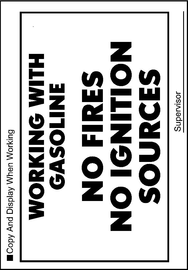
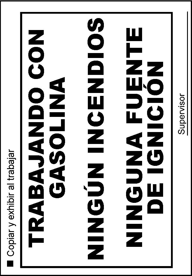
27 IV. FRAME REPLACEMENT WORK PROCEDURE A. SAFETY CHECKLIST & PRECAUTIONS WHEN DRAINING THE FUEL SYSTEM Always remember SAFETY FIRST. Be extremely careful when handling fuel to prevent fires from occurring. Before beginning work on the fuel system, perform the following safety check list. Before removing any fuel system part, drain all fuel to prevent spilling. 1. AIR VENTILATION Perform work in a well ventilated area. DO NOT work underground or in an area where fuel vapors may fill the room due to poor ventilation. Quickly clean up any spilled fuel with a dry cloth and dissipate the fuel vapors. Dry all cloths that have come in contact with fuel in a well ventilated area and dispose of them properly (according to applicable local regulations). 2. FIRES AND IGNITION SOURCES ARE STRICTLY PROHIBITED Fires and ignition sources are prohibited while working on the fuel system. Clearly display the sign found on the next page stating WORKING WITH GASOLINE, NO FIRES OR IGNITION SOURCES. Smoking is prohibited near the work area. DO NOT work in areas where there are welders, grinders, drills, electric motors, heaters, etc. DO NOT use work lamps or any other electrical appliance due to the risk of sparks flying from the power switch or a rise in temperature. DO NOT use metal hammers while working, due to the risk of flying sparks. DO NOT start any engines or perform any of the above in neighboring work bays. 3. FIRE EXTINGUISHER Have a fire extinguisher ready and available before beginning work. 4. PREVENT STATIC ELECTRICITY To help prevent static electricity, lightly wet the floor with water, but not to the point where it creates a hazardous working condition. Place appropriate warning cones or stand signs around the area as a caution. 5. PRECAUTIONS WHEN USING A LIFT For bays equipped with auto lifts, cover all access cover joints with duct tape. In the event that fuel has leaked inside the auto lift, remove the access cover and clean up any spilled fuel. Dissipate fuel vapors until the smell is gone. 6. PREVENT THE FUEL FROM SPRAYING When disconnecting any fuel tubes, pipes, hoses or connectors there may still be some pressure remaining, even after discharging the system. To prevent the fuel from spraying, cover the tubes, pipes or connectors with a shop rag before disconnecting. Remember to always wear protective goggles especially when disconnecting fuel tubes, pipes, hoses or connectors. 7. PREVENT THE FUEL FROM CONTACTING OTHER PARTS Do not allow the fuel to come in contact with any parts made of rubber or leather. 8. ASSIGN A SAFETY SUPERVISOR Assign a safety supervisor to be in charge of all safety precautions and fire hazards around the work area. 26
28 27
29 28
30 B. REMOVE THE BED ASSY If the frame is perforated, ONLY raise the vehicle high enough to remove the tires. For added safety and support place jack stands under the front and rear portions of the frame. DO NOT work directly underneath the vehicle when performing bed assy removal. The actual vehicle specs, equipment and parts required may differ than what is shown. Please use the correct specifications and parts for the model you are working on. For additional repair information, please reference the appropriate repair manual found on TIS for the vehicle you are working on. 1. CENTER THE VEHICLE BETWEEN THE LIFT ARMS a) Verify the vehicle is aligned with the center point of the lift to prevent interference and damage to the frame and/or lift. 2. REMOVE THE FOLLOWING PARTS Rear Bumper Assy Rear Tail/Combination Light LH/RH Rear Mudguard LH/RH (If Equipped) Side Step Assy LH/RH (If Equipped) Rocker Panel Molding LH/RH (If Equipped) Body Rocker Panel Molding Assy LH (If Equipped) Outside LH Back Door Molding Sub-Assy (If Equipped) Quarter Panel Wheel Opening Molding LH Left Rear Wheel Well Liner NOTE: Be careful not to damage the rear tail/combination lights when removing them. 3. REMOVE THE WIRE HARNESS a) Disconnect the clamps, connectors and the frame wire harness from the bed assy. NOTE: The number of connectors may differ depending on the vehicle specification. Be careful not to damage the wire harness clamps when removing them. 4. DISCONNECT THE FUEL INLET PIPE SUB-ASSY a) Remove the bolt and disconnect the fuel inlet pipe subassy. 5. REMOVE THE BED ASSY a) Using a Torx T55H Socket, remove the 6 Torx bolts from the bed assy. NOTE: Use 4 or more people to remove the bed assy from the frame. Evenly support the bed assy when removing it. Be careful not to damage the filler tubes when removing the bed. 29
31 C. DISCHARGE THE FUEL SYSTEM PRESSURE DO NOT disconnect any part of the fuel system until you have discharged the fuel system pressure. Even after discharging the fuel system pressure, place a piece of cloth around the tubes, pipe, hoses and connectors as you separate them to reduce the risk of fuel spraying on yourself, in the engine compartment and onto other parts. For additional repair information, please reference the appropriate repair manual in TIS for the vehicle you are working on. 1. CHECK FOR DTCs 2. RECORD THE RADIO STATION PRESETS 3. DISCHARGE THE FUEL SYSTEM PRESSURE a) Remove the No. 2 fuel tank protector. (If Equipped) b) Disconnect the fuel pump connector. c) Start the engine. d) After the engine has stopped, turn the ignition switch OFF. e) Crank the engine again to check that it does not start. NOTE: Please make sure to follow the procedure listed above. This will prevent a large amount of gasoline from spilling out when high pressure fuel tube is disconnected. 4. DISCONNECT THE NEGATIVE (-) BATTERY TERMINAL NOTE: Wait 90 seconds after the negative (-) terminal cable is disconnected from the battery before proceeding. Doing so will prevent the SRS from being deployed (i.e. airbag, seat belt pretensioner, etc.). 30
32 D. REMOVE THE CAB BODY ASSY If the frame is perforated, ONLY raise the vehicle high enough to remove the tires. For added safety and support place jack stands under the front and rear portions of the frame. DO NOT work directly underneath vehicle when performing cab assy removal, unless noted. The actual vehicle specs, equipment and parts required may differ than what is shown. Please use the correct specs and parts for the model you are working on. For additional repair information, please reference the appropriate repair manual in TIS for the vehicle you are working on. 1. REMOVE THE ENGINE UNDER COVERS NOTE: Use precaution when performing this step, as you will need to work underneath the vehicle. 2. EVACUATE THE REFRIGERANT FROM THE AIR CONDITIONING SYSTEM 3. DRAIN THE FOLLOWING FLUIDS Coolant (including engine block) Brake Fluid Clutch Fluid (Manual Transmission Vehicles Of 1GR-FE Only) Front Differential Fluid (4WD Only) NOTE: DO NOT remove the radiator cap while the radiator and engine are hot, doing so may cause the coolant to spray out causing potential injuries. 4. REMOVE THE FOLLOWING BODY COMPONENTS Radiator Grille Front Bumper Filler LH/RH Front Fender Mudguard LH/RH Front Bumper Assy Front Bumper Reinforcement Front No.2 Bumper Extension Sub-assy LH/RH 5. REMOVE THE FOLLOWING INTERIOR COMPONENTS Front Door Scuff Plate LH/RH Front Floor Footrest Cowl Side Trim Board LH/RH 6. REMOVE THE INSTRUMENT PANEL BOX 31
33 7. DISCONNECT THE FRAME WIRE HARNESS a) Disconnect the 5 clamps. b) Disconnect the connector(s). c) Remove the frame wire harness grommet from the cab assy. d) Pull out the frame wire harness from the vehicle cab assy. NOTE: The number of connectors may differ depending on the model. 8. REMOVE THE GLOVE BOX AND LOWER INSTRUMENT PANEL FINISH PANEL a) Remove the glove box. b) Remove the bolt and the lower instrument panel finish panel. 9. DISCONNECT THE ENGINE WIRE HARNESS a) Disconnect each connector and clamp from the ECM and remove the engine wire harness. NOTE: The number of connectors may differ depending on the model. 32
34 10. REMOVE THE FOLLOWING PARTS Rear Console Box (for Separate Seat Type) Front Console Box Voltage Inverter Assy (If Equipped) Manual Transmission Shift Lever (Manual Trans Vehicles Only) 11. DISCONNECT THE PARKING BRAKE CABLES For Separate Seat Type: a) Remove the 2 clips. b) Disconnect the 2 parking brake cables. For Bench Seat Type: c) Turn back the floor carpet. d) Remove the 3 bolts and the parking brake cable joint protector. e) Remove the 2 clips. f) Disconnect the 2 parking brake cables. 12. REMOVE THE FOLLOWING PARTS V-Bank Cover (1GR-FE Only) Air Cleaner Hose and Air Cleaner Assy 13. DISCONNECT THE NO.2 ENGINE WIRE HARNESS a) Remove the nut and disconnect the (+) positive battery cable. b) Remove the bolt and disconnect the ground wire. c) Disconnect the 2 clamps. d) Remove the No.1 upper relay block cover. e) Disconnect the 3 connectors. f) Remove the nut and disconnect the fuse box wire harness. 33
35 LH Side 14. DISCONNECT THE SKID CONTROL SENSOR WIRE HARNESS a) Disconnect the harness clamp and front skid control sensor connector. b) Repeat the procedure on the opposite side. RH Side 15. DISCONNECT THE FRONT DIFFERENTIAL BREATHER TUBES (4WD ONLY) a) Disconnect the front differential breather tubes. NOTE: There may be 2 front differential breather tubes depending on the vehicle model. 16. DISCONNECT THE FUEL PIPES AND VAPOR FEED HOSE a) Remove the 2 fuel pipe clamps. b) Disconnect the No. 1 and No. 2 fuel pipe. NOTE: Put a shop towel under the fuel pipe to catch any spilled fuel. 17. DISCONNECT THE VACUUM HOSE a) Disconnect the vacuum hose. 34
36 18. REMOVE THE FOLLOWING PARTS Radiator Support To Frame Seal Radiator Inlet Hose Radiator Outlet Hose Fan Shroud Radiator Assy 19. DISCONNECT THE NO.1 HOSE (2TR-FE ONLY) a) Disconnect the No.1 hose. 20. DISCONNECT THE GROUND WIRE (2TR-FE ONLY) a) Remove the bolt and disconnect the ground wire. 21. DISCONNECT POWER STEERING PUMP OIL RESERVOIR ASSY (1GR-FE ONLY) a) Disconnect power steering pump oil reservoir assy. 22. DISCONNECT THE GROUND WIRE (1GR-FE ONLY) a) Remove the bolt and disconnect the clamp and the ground wire. 23. DISCONNECT THE ENGINE WIRE HARNESS a) Disconnect the clamp. b) Remove the engine wire harness container from the cowl panel. 24. DISCONNECT THE WATER / HEATER HOSES, ENGINE SIDE LH Side 25. REMOVE THE FRONT FENDER APRON SEALS 4WD, Pre-Runner Only (Shown): a) Remove the 20 clips and 4 front fender apron seals. 2WD Only: b) Remove the 22 clips and 4 front fender apron seals. RH Side 35
37 26. DISCONNECT THE AIR CONDITIONING DISCHARGE AND SUCTION HOSES FROM THE COMPRESSOR LH Side 27. DISCONNECT THE FRONT BRAKE TUBES a) Disconnect the front brake tube. b) Repeat the procedure on the opposite side. RH Side 28. DISCONNECT THE STEERING SLIDING YOKE NOTE: Use precaution when performing this step, as you will need to work underneath the vehicle. a) Make sure the front wheels are in a straight-ahead position and the steering wheel is centered. b) Using the seat belt, hold the steering wheel in position as shown in the illustration, in order to prevent damage to the spiral cable. c) Place match marks on the steering sliding yoke and No.2 intermediate shaft. d) Loosen bolt (A) and remove bolt (B). e) Disconnect the steering sliding yoke from the No.2 intermediate shaft. NOTE: If the steering sliding yoke is stuck, tap it from below with a brass hammer to disconnect it. 29. DISCONNECT THE SHIFT CABLE (AUTO TRANS ONLY) Cable Type: a) Remove the clip. b) Remove the nut and disconnect the shift cable. Rod Type: c) Remove the pin and clip, disconnect the shift cable. NOTE: Use precaution when performing this step, as you will need to work underneath the vehicle. 36
38 30. DISCONNECT THE CLUTCH RELEASE CYLINDER ASSY (2TR FE MANUAL TRANS ONLY) a) Remove the bolt and disconnect the clutch hose. b) Remove the 2 bolts and disconnect the clutch release cylinder. NOTE: Use precaution when performing this step, as you will need to work underneath the vehicle. 31. DISCONNECT THE NO.1 CLUTCH HOSE (1GR-FE MANUAL TRANS ONLY) a) Disconnect the clutch release cylinder tube from the clutch hose. b) Remove the clip and disconnect the clutch hose. 32. DISCONNECT THE NO.2 FUEL HOSE a) Remove the clip and disconnect the No.2 fuel hose. NOTE: Use precaution when performing this step, as you will need to work underneath the vehicle. 33. DISCONNECT THE FUEL TANK TUBES a) Remove the fuel pipe clamp. b) Disconnect the 2 fuel tank tubes. NOTE: Use precaution when performing this step, as you will need to work underneath the vehicle. 34. DISCONNECT THE REAR BRAKE TUBES a) Disconnect the 2 rear brake tubes. b) Remove the bolt and disconnect the 2 way. NOTE: Use precaution when performing this step, as you will need to work underneath the vehicle. 35. DISCONNECT THE PARKING BRAKE CABLES NOTE: Use precaution when performing this step, as you will need to work underneath the vehicle. 37
39 36. REMOVE THE FOLLOWING PARTS Floor Board No.1/No.2 (Access Cab Only) Seat Floor Box (Access Cab Only) Rear Floor Side Service Hole Cover LH/RH (Access Cab Only) Luggage Compartment Side Tray (Double Cab Only) No.1 w/ Box Speaker Assy (If Equipped) 37. REMOVE THE CAB BODY ASSY USING AN ABOVE GROUND LIFT a) Remove the 6 nuts and 6 washers. b) Set the lift arms under the cab body assy so they DO NOT interfere with the frame or cab mounts. c) Check that all wire harnesses, hoses, cables and the steering shaft are disconnected. d) Mark the location of the tires so it will be easier to install the cab onto the new frame. e) Lift the cab assy up slowly, making sure it does not interfere with anything while being raised. f) Raise the cab assy high enough so that the top of the engine clears the lowest point of the cab assy. g) Pull the frame assy out from under the vehicle. h) Lower the cab assy all the way down and leave it on the lift. NOTE: Center the cab assy weight on the lift arms so that it does not slant/tilt to one side. Raise the cab assy slightly off the frame and verify that it is held securely by the lift arms. The center of gravity of the cab body may become nose heavy depending on placement of the lift arm which could cause the cab to fall when lifted. To prevent this, use weights to establish a balance and secure the cab body to the lift arm using ratchet tie down belts. DO NOT work directly underneath the vehicle when pulling the frame assy out from under. DO NOT remove the cab mount bolts, they will be used as guides during cab assy reinstallation. 38
40 E. DISASSEMBLE THE FRAME 1. PLACE THE FRAME ON A LIFT a) Place the frame on the lift, and secure it with a ratcheting tie down strap. This will prevent the frame from tilting or falling off as parts are removed. Ratcheting Tie Downs: Qty 1 (Length: 2 in X 27 ft and Min. Work Load Capacity: 3,000 lbs) 2. REMOVE THE FOLLOWING PARTS Wheels Propeller Shaft Heat Insulator (If Equipped) Front Propeller Shaft Assy (4WD Only) Exhaust Pipe Stopper Bracket (If Equipped) Rear Propeller Shaft Assy Insert SST into trans after the Rear Prop Shaft is removed to prevent oil leakage (2WD Only) NOTE: Place match marks on the front (if equipped) and rear propeller shafts prior to removal. 3. REMOVE THE EXHAUST SYSTEM (1GR-FE ONLY) a) Remove the 2 bolts and 4 exhaust pipe supports. b) Remove the center exhaust pipe assy and exhaust pipe supports. c) Remove the exhaust pipe gasket. d) Disconnect the 2 oxygen sensor connectors. e) Remove the 6 nuts and 2 exhaust pipe supports. f) Remove the front exhaust pipe assy and exhaust pipe supports. g) Remove the 2 exhaust pipe gaskets. 4. REMOVE THE EXHAUST SYSTEM (2TR-FE ONLY) a) Remove the 2 bolts and 4 exhaust pipe supports. b) Remove the center exhaust pipe assy and exhaust pipe supports. c) Remove the exhaust pipe gasket. d) Disconnect the 2 oxygen sensor connectors. e) Disconnect the 2 oxygen sensor wire harness clamps. f) Remove the 2 bolts and exhaust pipe support. g) Remove the front exhaust pipe assy and exhaust pipe supports. h) Remove the 2 exhaust pipe gaskets. 39
41 5. REMOVE THE FOLLOWING PARTS No.1 Fuel Tank Protector Assy (If Equipped) Fuel Tank Strap Fan /V-belt Fuel Tank Charcoal Canister Assy 6. REMOVE AND SET ASIDE THE POWER STEERING PUMP ASSY a) Disconnect the connector. b) Disconnect the clamp. (1GR-FE Only) c) Remove the bolt and disconnect the ground wire. (1GR-FE Only) d) Remove the 2 bolts and the power steering vane pump. NOTE: DO NOT disconnect the power steering pump hoses or tubes. Keep the power steering pump reservoir upright to prevent the fluid from leaking out. 7. REMOVE THE FOLLOWING PARTS Intake Air Surge Tank (1GR-FE Only) Intake Air Connector (2TR-FE Only) 8. DISCONNECT THE OIL COOLER TUBE (AUTO TRANS ONLY) a) Remove the bolts and disconnect the oil cooler tube. LH Side 9. REMOVE THE ENGINE AND TRANSMISSION ASSY a) Remove the bolt and disconnect the ground wire. (LH Side) b) Disconnect the connector and clamp. (4WD Only) c) Disconnect and remove the necessary items/parts to prepare the engine and transmission assy for removal. d) Install the engine hanger. 4WD Only For 1GR-FE: = No.1 Engine Hanger = No.2 Engine Hanger A87 = 4 Bolts For 2TR-FE: = No.1 Engine Hanger = No.2 Engine Hanger A1020 = 2 Bolts 40
42 e) Remove the engine and transmission assy. NOTE: ALWAYS use 2 engine hoists/cranes to lift it. DO NOT use 1 engine hoist/crane to lift the engine & transmission assy, as the unbalanced weight may lead to an accident or injury. ONLY use engine hoists/cranes that can properly support the weight of the engine and transmission assy. Carefully adjust the 2 engine hoists/cranes used so that the engine and transmission assy is properly balanced. 10. DISCONNECT THE FRONT SKID CONTROL SENSOR WIRE HARNESS (2WD ONLY) a) Remove the bolt, disconnect the clamp and skid control sensor wire harness. b) Repeat the procedure on the opposite side. 11. DISCONNECT THE FRONT SKID CONTROL SENSOR WIRE HARNESS (4WD, PRE-RUNNER ONLY) a) Remove the bolt and disconnect the skid control sensor wire harness. b) Repeat the procedure on the opposite side. 12. DISCONNECT THE FRONT BRAKE HOSE (2WD ONLY) a) Disconnect the front brake tube from the brake hose. b) Remove the 2 bolts and disconnect the front brake hose and flexible hose bracket. c) Repeat the procedure on the opposite side. 13. DISCONNECT THE FRONT BRAKE HOSE (4WD, PRE-RUNNER ONLY) a) Disconnect the front brake tube from the brake hose. b) Remove the bolt and disconnect the front brake hose and flexible hose bracket. c) Repeat the procedure on the opposite side. 41
43 14. REMOVE THE FOLLOWING PARTS Front Axle Hub Grease Cap (4WD Only) Tie Rod End* Front Axle Shaft Nut (4WD Only) Front Stabilizer Link Assy * SST (2WD), SST (4WD, Pre-Runner) disconnect the tie rod end. 15. REMOVE THE FRONT SUSPENSION UPPER ARM AND STEERING KNUCKLE ASSY (2WD ONLY) a) Remmove the 2 bolts (A). b) Remove the 2 bolts (B), 2 nuts, 2 washers and front suspension upper arm w/ steering knuckle. c) Repeat the procedure on the opposite side. 16. REMOVE THE FRONT SUSPENSION UPPER ARM AND STEERING KNUCKLE ASSY (4WD, PRE-RUNNER ONLY) a) Remove the 2 bolts (A). b) Remove the bolt (B), nut, 2 washers and front suspension upper arm w/ steering knuckle. c) Repeat the procedure on the opposite side. NOTE: If the drive shaft is difficult to disconnect, tap the drive shaft loose with a plastic hammer. 17. REMOVE THE FOLLOWING PARTS Front Drive Shaft Assy (4WD Only)* Power Steering Link Assy w/ Pump Front Suspension Member Brace Sub-Assy Front Differential Carrier (4WD Only) Front Stabilizer Bar Lower Ball Joint** Front Shock Absorber Assy Front Spring Bumper*** *SST ( ), **SST ***SST NOTE: When removing the power steering link with the pump, have one person support the power steering link and the other support the pump and keep it upright to avoid fluid leakage. If the drive shaft is difficult to remove tap it with a plastic hammer. Be careful not to damage the dust cover and oil seal. 18. REMOVE THE PARKING BRAKE CABLES a) Remove the 8 bolts and parking brake cables. 42
44 19. REMOVE THE FRAME WIRE HARNESS a) Remove the bolt and disconnect the ground wire (If Equipped). b) Disconnect the clamps and remove the frame wire harness. NOTE: The number of wire harness clamps will differ depending on the vehicle specification. Take care not to damage or break the wire harness clamps during removal. Front Side 20. REMOVE THE HARNESS BRACKETS a) Remove the 2 bolts and 2 brackets. Rear Side 21. DISCONNECT THE BRAKE HOSE a) Disconnect the No.5 rear brake tube. b) Disconnect the No.6 rear brake tube. c) Remove the 2 clips and 2 bolts, disconnect the brake hose and the No.2 flexible hose bracket. 22. REMOVE THE FOLLOWING PARTS Rear Stabilizer Bar (If Equipped) Rear Differential Assy Rear Shock Absorber Assy No.1 Rear Spring Bumper (2WD Only) NOTE: Cut the rear differential U bolts off if the nuts cannot be removed. 23. REMOVE THE NO.2 CHARCOAL CANISTER PIPE a) Disconnect the clamps and remove the No.2 charcoal canister pipe. 43
45 24. REMOVE THE FRAME AUXILIARY CROSSMEMBER EXTENSIONS (IF EQUIPPED) a) Remove the 2 bolts and frame auxiliary crossmember extensions. 25. REMOVE THE HOOK a) Remove the 2 bolts and hook. 26. REMOVE THE REAR ENGINE MOUNTING REINFORCES (1GR-FE ONLY) a) Remove the 2 bolts and 2 rear engine mounting reinforces. 27. REMOVE THE PARKING BRAKE CABLE HEAT INSULATOR (IF EQUIPPED) a) Remove the 2 bolts and parking brake cable heat insulator. 28. REMOVE THE OXYGEN SENSOR BRACKETS (2TR-FE ONLY) a) Remove the 2 bolts and 2 brackets. 44
46 29. REMOVE THE NO.1 RECEIVER HITCH ATTACHMENT REINFORCEMENT (IF EQUIPPED) a) Remove the 2 bolts and No.1 receiver hitch attachment reinforcement. 30. REMOVE THE CLIPS 31. REMOVE THE FOLLOWING PARTS Front Suspension Lower Arm Cab Mounts (QTY:6) Rear Leaf Spring Assy 32. REMOVE THE FRAME FROM THE LIFT a) Remove the ratcheting tie down strap and the frame from the lift. 45
47 F. ASSEMBLE THE NEW FRAME 1. PLACE THE NEW FRAME ON THE LIFT a) Place the NEW frame on the lift, and secure it with a ratcheting tie down strap. This will prevent the frame from tilting or falling off as parts are installed. Ratcheting Tie Downs: Qty 1 (Length: 2 in X 27 ft and Min. Work Load Capacity: 3,000 lbs) 2. INSTALL THE NEW REAR LEAF SPRINGS a) Install the NEW rear leaf spring with the all NEW parts (shackle, bushings, bolts, washers and nuts) and torque to spec. Torque Spec: 120 N m (1224 kgf cm, 89 ft lbf) b) Repeat the procedure on the opposite side. NEW Replacement Parts Shackle Kit, RR Spring Bolt, Flange A0050 Nut, Flange Washer, Plain 1 2 Varies** Spring Assy, RR RH NA* 1 Varies** Spring Assy, RR LH NA* 1 *Individual Part(s) **Only 1 part used, part number varies by vehicle type. **Replacement leaf springs will come in either 3 or 4 leaf stacks, ensure that the left and right springs contain the same amount of leafs. If replacement springs come in a 4 leaf stack, bump stop replacement is required (new bump stops will be provided) NEW Replacement Parts Holder, Body Support Bracket INSTALL THE NEW CLIPS 4. REINSTALL THE NO.1 RECEIVER HITCH ATTACHMENT REINFORCEMENT (IF EQUIPPED) a) Reinstall the No.1 receiver hitch attachment reinforcement with the 2 bolts and torque to spec. Torque Spec: 45 N m (459 kgf cm, 33 ft lbf) 5. REINSTALL THE NO.1 REAR SPRING BUMPER (2WD ONLY) a) Reinstall the rear spring bumper with the 2 nuts and torque to spec. b) Repeat the procedure on the opposite side. Torque Spec: 15 N m (153 kgf cm, 11 ft lbf 46
48 NEW Replacement Parts A0151 Bolt, w/ Washer NA* 2 *Individual Part(s) 6. REINSTALL THE PROPELLER SHAFT HEAT INSULATOR (IF EQUIPPED) a) Reinstall the propeller shaft heat insulator with the 2 NEW bolts and torque to spec. Torque Spec: 15.7 N m (160 kgf cm, 12 ft lbf) 7. REINSTALL THE PARKING BRAKE CABLE HEAT INSULATOR (IF EQUIPPED) a) Reinstall the parking brake cable heat insulator with the 2 bolts and torque to spec. Torque Spec: 12.5 N m (127 kgf cm, 9 ft lbf) 8. REINSTALL THE OXYGEN SENSOR BRACKETS (2TR-FE ONLY) a) Reinstall the 2 brackets with the 2 bolts and torque to spec. Torque Spec: 14 N m (143 kgf cm, 10 ft lbf) 9. REINSTALL THE REAR ENGINE MOUNTING REINFORCES (1GR-FE ONLY) a) Reinstall the rear engine mounting reinforces with the 2 bolts and torque to spec. Torque Spec: 31 N m (316 kgf cm, 23 ft lbf) NEW Replacement Parts A0192 Bolt, w/ Washer A0193 Bolt, w/ Washer NA* 2 *Individual Part(s) 10. REINSTALL THE HOOK a) Reinstall the hook with the 2 NEW bolts and torque to spec. Torque Spec: 70 N m (714 kgf cm, 52 ft lbf) 47
49 11. REINSTALL THE FRAME AUXILIARY CROSSMEMBER EXTENSION (IF EQUIPPED) a) Reinstall the 2 frame auxiliary crossmember extensions with the 2 bolts and torque to spec. Torque Spec: 45 N m (459 kgf cm, 33 ft lbf) 12. REINSTALL THE CAB MOUNTS a) Reinstall cab mounts No.1 b) Reinstall cab mounts No.2 and No.3 with the 8 bolts and torque to spec. Torque Spec: 61 N m (622 kgf cm, 45 ft lbf) 13. INSTALL THE NEW FRONT SUSPENSION LOWER ARM (2WD ONLY) a) Install the NEW front suspension lower arm with the 2 NEW nuts, 2 NEW No.1 camber adjust cams and 2 NEW No.2 camber adjust cams, then torque to spec. Torque Spec: 210 N m (2141 kgf cm, 155 ft lbf) b) Repeat the procedure on the opposite side. NEW Replacement Parts Arm Sub-Assy, Suspension LWR RH w/bush NA* Arm Sub-Assy, Suspension LWR LH w/bush NA* Cam Assy, Camber Adjust Cam, Camber Adjust No A0013 Nut, Flange NA* 4 *Individual Part(s) 2WD Only 48
50 14. INSTALL THE NEW FRONT SUSPENSION LOWER ARM (4WD, PRE-RUNNER ONLY) a) Install the NEW front suspension lower arm with the NEW bolt, nut, NEW toe adjust cam, NEW No.2 toe adjust cam, NEW No.1 camber adjust cam and NEW No.2 camber adjust cam, then torque to spec. Torque Spec: 135 N m (1377 kgf cm, 100 ft lbf) b) Repeat the procedure on the opposite side. NEW Replacement Parts Arm Sub-Assy, Suspension LWR RH w/bush NA* Arm Sub-Assy, Suspension LWR LH w/bush NA* Cam Assy, Camber Adjust Cam, Camber Adjust No Cam Sub- Assy, Toe Adjust Plate, Toe Adjust, No A0166 Bolt, w/ Washer 8 2 *Individual Part(s) 4WD, Pre-Runner Only NEW Replacement Parts (2WD Only) Bumper, Sub-Assy FR NA* AD010 Spring** NA* 2 *Individual Part(s) **Only 1 part used, part number varies by vehicle type. 15. INSTALL THE NEW FRONT SPRING BUMPER a) Using the SST , install the NEW front spring bumpers and torque to spec. Torque Spec: 31 N m (316 kgf cm, 23 ft lbf) b) Repeat the procedure on the opposite side. NEW Replacement Parts ( 4WD, Pre-Runner Only ) Bumper, Sub-Assy FR Spring INSTALL THE NEW REAR BRAKE TUBES a) Install the NEW rear brake tubes with the NEW clamp(s). NEW Replacement Parts NA* Tube, RR Brake, No.5** NA* NA* NA* Tube, RR Brake, No.6** NA* NA* A0004 Clamp (Regular Cab) NA* A0004 Clamp (Access Cab) NA* A0004 Clamp (Double Cab) NA* A1006 Clamp 2 3 *Individual Part(s) **Only 1 part used, part number varies by vehicle type. 49
51 NEW Replacement Parts Support, Fuel Return & Main Tube REINSTALL THE NO. 2 CHARCOAL CANISTER PIPE a) Install the NEW fuel return and main tube support. b) Reinstall the No.2 charcoal canister pipe. NEW Replacement Parts A0169 Bolt, w/ Washer Carrier Assy, Spare NA* Wheel** NA* 1 *Individual Part(s) **Only 1 part used, part number varies by vehicle type. 18. INSTALL THE NEW SPARE TIRE CARRIER ASSY a) Install the NEW spare tire carrier assy with the 4 NEW bolts and torque to spec. Torque Spec: 20 N m (204 kgf cm, 15 ft lbf) NEW Replacement Parts Rear Differential Assy A0001 NA* A0002 Bolt, U** NA* A0005 NA* A0050 Nut, Flange Washer, Plain Bump Stop*** NA* 2 *Individual Part(s) **Only 1 part used, part number varies by vehicle type. *** Only replaced if leaf springs replacement springs are a 4 leaf configuration. Rear Shock Absorber Assy A0010 Nut, Lock 2 2 Rear Stabilizer Bar A91 Bolt, w/ Washer NA* 4 *Individual Part(s) 19. REINSTALL THE FOLLOWING PARTS Rear Differential Assy Reinstall with the 4 NEW U -bolts, 2 spring seats, 2 spring bumpers (If Equipped), 8 NEW flange nuts and 8 NEW plain washers, then torque to spec. Torque Spec: 50 N m (510 kgf cm, 37 ft lbf) Rear Shock Absorber Assy Reinstall rear shock absorber assy with the bolt, nut and washer. (Lower side) Torque Spec: Nut - 58 N m (591 kgf cm, 43 ft lbf) Reinstall the 3 retainers, 2 cushions and NEW nut, then torque to spec. (Upper side) Torque Spec: Nut - 20 N m (204 kgf cm, 15 ft lbf) Repeat the procedure on the opposite side. Rear Stabilizer Bar (If Equipped) Reinstall with the 2 brackets and NEW 4 bolts, then torque to spec. Torque Spec: 27 N m (275 kgf cm, 20 ft lbf) Reconnect the 2 stabilizer bar links with the 4 nuts, then torque to spec. Torque Spec: 65 N m (663 kgf cm, 48 ft lbf) 50
52 NEW Replacement Parts Bracket, Flexible Hose, No A0169 Bolt, W/ Washer 13 or 2 NA* A0007 Clip 2 2 *Individual Part(s) 20. RECONNECT THE BRAKE HOSE a) Install the NEW No.2 flexible hose bracket with the 2 NEW bolts. b) Reconnect the 2 brake hoses with the 2 NEW clips. c) Reconnect the No.5, No.6 rear brake tubes and torque to spec. Torque Spec: Flexible hose bracket - 29 N m (296 kgf cm, 21 ft lbf) Rear brake tube N m (155 kgf cm, 11 ft lbf) Front Side 21. REINSTALL THE HARNESS BRACKETS a) Reinstall the 2 brackets with the 2 bolt and torque to spec. Torque Spec: 14 N m (143 kgf cm, 10 ft lbf) Rear Side 22. INSTALL THE NEW FRAME WIRE HARNESS a) Reconnect the clamps to install the NEW frame wire harness. b) Reconnect the ground wire with the bolt and torque to spec. Torque Spec: 12.7 N m (130 kgf cm, 9 ft lbf) NOTE: The number of wire harness clamps will differ depending on the vehicle spec. NEW Replacement Parts NA* A00 NA* A10 NA* A20 Wire, Frame** NA* A30 NA* A40 NA* A50 NA* 1 *Individual Part(s) **Only 1 part used, part number varies by vehicle type. 51
53 23. REINSTALL THE PARKING BRAKE CABLES a) Reinstall the 2 parking brake cables with the 8 bolts, then torque to spec. Torque Spec: 12.5 N m (127 kgf cm, 9 ft lbf) NEW Replacement Parts A0005 Nut, Castle Pin, Cotter REINSTALL THE LOWER BALL JOINT a) Reinstall the lower ball joint with the NEW nut and torque to spec. Torque Spec: 160 N m (1632 kgf cm, 118 ft lbf) b) Install the NEW cotter pin. c) Repeat the procedure on the opposite side. 25. REINSTALL FRONT DIFFERENTIAL CARRIER (4WD ONLY) a) Reinstall the front differential carrier with the 2 bolts, 4 stoppers and 3 nuts, then torque to spec. Torque Spec: Except TMMTX Made Bolt N m (1400 kgf cm, 101 ft lbf) Nut 87.2 N m (889 kgf cm, 64 ft lbf) Torque Spec: TMMTX Made Bolt N m (1310 kgf cm, 95 ft lbf) Nut N m (831 kgf cm, 60 ft lbf) 2TR-FE 1GR-FE 26. REINSTALL THE POWER STEERING LINK ASSY W/ POWER STEERING VANE PUMP a) Reinstall the power steering link assy w/ power steering vane pump with the bolts and nuts, then torque to spec. Torque Spec: Bolt A - 92 N m (938 kgf cm, 68 ft lbf) Bolt B - 28 N m (286 kgf cm, 21 ft lbf) NOTE: When reinstalling the power steering link with the pump, have one person support the power steering link and the other support the pump. Keep the power steering pump reservoir upright to prevent the fluid from leaking out. 52
54 27. RECONNECT THE FRONT DIFFERENTIAL BREATHER TUBE (4WD ONLY) a) Reconnect the front differential breather tube with the bolt and 2 clamps, then torque to spec. Torque Spec: 12.7 N m (130 kgf cm, 9 ft lbf) NEW Replacement Parts Nut, Flange REINSTALL THE FRONT SHOCK ABSORBER ASSY a) Install the 3 NEW nuts (A) and torque to spec. b) Reinstall the front shock absorber assy with the bolt and nut (B), then torque to spec. Torque Spec: Nut A - 64 N m (653 kgf cm, 47 ft lbf) Nut B - 83 N m (846 kgf cm, 61 ft lbf) c) Repeat the procedure on the opposite side. 29. REINSTALL THE FRONT STABILIZER BAR NEW Replacement Parts (2WD Only) A0161 Bolt, w/ Washer NA* 4 *Individual Part(s) 2WD Only a) Reinstall the stabilizer bar with 2 brackets and 4 NEW bolts, then torque to spec. (2WD Only) b) Reinstall the stabilizer bar with 2 brackets and 4 bolts, then torque to spec. (4WD, Pre-Runner Only) Torque Spec: 2WD - 21 N m (214 kgf cm, 15 ft lbf) 4WD, Pre-Runner - 40 N m (408 kgf cm, 30 ft lbf) 30. REINSTALL THE SUSPENSION MEMBER BRACE SUB- ASSY a) Reinstall the suspension member brace sub-assy with 8 bolts (2WD Only) or 7 bolts (4WD, Pre-Runner Only), then torque to spec. Torque Spec: 45 N m (459 kgf cm, 33 ft lbf) 4WD, Pre-Runner Only 53
55 31. REINSTALL THE FRONT DRIVE SHAFT ASSY (4WD ONLY) NEW Replacement Parts Ring, Drive Shaft Snap NA* Seal, Type T Oil (LH) Seal, Type T Oil (RH) 3 1 *Individual Part(s) a) Install a NEW snap ring. b) Reinstall the front drive shaft assy. c) Repeat the procedure on the opposite side. NOTE: Be careful not to damage the dust cover and oil seal. If the oil seal is damaged, replace the NEW parts. 32. REINSTALL THE FRONT SUSPENSION UPPER ARM AND STEERING KNUCKLE ASSY (2WD ONLY) a) Reinstall the front suspension upper arm w/ steering knuckle with the 2 bolts (A), 2 nuts and 2 washers, then torque to spec. Torque Spec: Bolt A - 82 N m (836 kgf cm, 60 ft lbf) b) Reinstall the 2 bolts (B), then torque to spec. Torque Spec: Bolt B N m (1632 kgf cm, 118 ft lbf) c) Repeat the procedure on the opposite side. 33. REINSTALL THE FRONT SUSPENSION UPPER ARM AND STEERING KNUCKLE ASSY (4WD, PRE-RUNNER ONLY) a) Reinstall the front suspension upper arm w/ steering knuckle with the bolt (A), nut and 2 washers, then torque to spec. Torque Spec: Nut N m (1173 kgf cm, 85 ft lbf) b) Reinstall the 2 bolts (B), then torque to spec. Torque Spec: Bolt B N m (1632 kgf cm, 118 ft lbf) c) Repeat the procedure on the opposite side. 34. REINSTALL THE FOLLOWING PARTS NEW Replacement Parts Tie Rod End Pin, Cotter** **Only 1 part used, part number varies by vehicle type. Front Stabilizer Link (2WD Only) Reinstall with 2 retainers, 2 cushions and nut, torque to spec. Torque Spec: 19 N m (194 kgf cm, 14 ft lbf) Reinstall the nut, then torque to spec. Torque Spec: 69 N m (704 kgf cm, 51 ft lbf) Repeat the procedure on the opposite side. Front Stabilizer Link (4WD, Pre-Runner Only) Reinstall front stabilizer link with 2 nuts, torque to spec. Torque Spec: 70 N m (714 kgf cm, 52 ft lbf) Repeat the procedure on the opposite side. Tie Rod End Reinstall tie rod end with nut and torque to spec. Torque Spec: 2WD - 49 N m (500 kgf cm, 36 ft lbf) 4WD, Pre-Runner - 91 N m (928 kgf cm, 67 ft lbf) Install the NEW cotter pin. Repeat the procedure on the opposite side. Front Axle Shaft Nut (4WD Only) Temporarily reinstall the front axle nut. Nut will be tightened when the vehicle is completed. Repeat the procedure on the opposite side. 54
TECHNICAL INSTRUCTIONS FOR LIMITED SERVICE CAMPAIGN (LSC) A0F 2000 THROUGH 2003 MODEL YEAR TUNDRA FRAME REPLACEMENT
 A0F 2000 THROUGH 2003 MODEL YEAR TUNDRA FRAME REPLACEMENT") TECHNICAL INSTRUCTIONS FOR LIMITED SERVICE CAMPAIGN (LSC) A0F 2000 THROUGH 2003 MODEL YEAR TUNDRA FRAME REPLACEMENT I. OPERATION FLOWCHART Verify Vehicle Eligibility 1. Check the VIN range. 2. Check the
TECHNICAL INSTRUCTIONS FOR LIMITED SERVICE CAMPAIGN (LSC) A0F 2000 THROUGH 2003 MODEL YEAR TUNDRA FRAME REPLACEMENT I. OPERATION FLOWCHART Verify Vehicle Eligibility 1. Check the VIN range. 2. Check the
* * * * * * * * * * * * * * * * * * * * * * * * * * * * * * * * * * * * * * * * * * * * * * * * * * * * * * * * * *
 TECHNICAL INSTRUCTIONS FOR LIMITED SERVICE CAMPAIGN CSD * * * * * * * * * * * * * * * * * * * * * * * * * * * * * CERTAIN 2001-2004 MODEL YEAR SEQUOIA * * * * * * * * * * * * * * * * * * * * * * * * *
FUEL SYSTEM PRECAUTION FU 1
 2GR-FE EL EL SYSTEM EL SYSTEM PRECAUTION 1 1. EXPRESSIONS OF IGNITION SWITCH (a) The type of the ignition switch used on this model differs according to the specifications of the vehicle. The expressions
ENGINE ASSEMBLY. COMPONENTS (Part 1)
") 1 of 32 ENGINE ASSEMBLY COMPONENTS (Part 1) 2 of 32 COMPONENTS (Part 2) 3 of 32 COMPONENTS (Part 3) 4 of 32 COMPONENTS (Part 4) 5 of 32 COMPONENTS (Part 5) 6 of 32 COMPONENTS (Part 6) 7 of 32 COMPONENTS
1 of 32 ENGINE ASSEMBLY COMPONENTS (Part 1) 2 of 32 COMPONENTS (Part 2) 3 of 32 COMPONENTS (Part 3) 4 of 32 COMPONENTS (Part 4) 5 of 32 COMPONENTS (Part 5) 6 of 32 COMPONENTS (Part 6) 7 of 32 COMPONENTS
CYLINDER HEAD (for Bank 2 4WD and Pre-Runner)
") 144 1GR-FE ENGINE MECHANICAL CYLINDER HEAD (for Bank 2 4WD and Pre-Runner) CYLINDER HEAD (for Bank 2 4WD and Pre-Runner) ENGINE 1GR-FE ENGINE MECHANICAL COMPONENTS 88 (897, 65) x4 88 (897, 65) x4 NO. 1
144 1GR-FE ENGINE MECHANICAL CYLINDER HEAD (for Bank 2 4WD and Pre-Runner) CYLINDER HEAD (for Bank 2 4WD and Pre-Runner) ENGINE 1GR-FE ENGINE MECHANICAL COMPONENTS 88 (897, 65) x4 88 (897, 65) x4 NO. 1
1GR-FE ENGINE CONTROL SYSTEM
 PREPARATION 1GR-FE ENGINE CONTROL SYSTEM 1GR-FE ENGINE CONTROL SYSTEM PREPARATION RECOMMENDED TOOLS 1 09040-00011 Hexagon Wrench Set (09043-20080) Socket Hexagon Wrench 8 (09043-20100) Socket Hexagon Wrench
SUSPENSION SYSTEM PROBLEM SYMPTOMS TABLE SP 1
 SUENSION SUENSION SYSTEM 1 SUENSION SYSTEM Suspension system Vehicle is unstable Bottoming Sways/pitches Wheels shimmy Abnormal tire wear Vehice pull PROBLEM SYMPTOMS TABLE Use the table below to help
OIL PUMP (for 4WD and Pre-Runner)
") 1GR-FE BRICATION OIL PUMP (for 4WD and Pre-Runner) OIL PUMP (for 4WD and Pre-Runner) ENGINE 1GR-FE BRICATION COMPONENTS 23 88 (897, 65) 88 (897, 65) NO. 1 ENGINE UNDER COVER SUB-ASSEMBLY FRONT PROPELLER
1GR-FE BRICATION OIL PUMP (for 4WD and Pre-Runner) OIL PUMP (for 4WD and Pre-Runner) ENGINE 1GR-FE BRICATION COMPONENTS 23 88 (897, 65) 88 (897, 65) NO. 1 ENGINE UNDER COVER SUB-ASSEMBLY FRONT PROPELLER
PARTIAL ENGINE ASSY COMPONENTS. Clip. Radiator Grille. Clip. Front Bumper Cover. Engine Under Cover LH. N m (kgf cm, ft lbf) : Specified torque
 : Specified torque") ENGINE MECHANICAL 1417 COMPONENTS 141FP01 Radiator Grille Front Bumper Cover Engine Under Cover RH Engine Under Cover LH A79361 962 1418 ENGINE MECHANICAL Heater Outlet Water Hose 7.0 (71, 62 in. lbf)
ENGINE MECHANICAL 1417 COMPONENTS 141FP01 Radiator Grille Front Bumper Cover Engine Under Cover RH Engine Under Cover LH A79361 962 1418 ENGINE MECHANICAL Heater Outlet Water Hose 7.0 (71, 62 in. lbf)
SUSPENSION SYSTEM PROBLEM SYMPTOMS TABLE SP 1
 SUENSION SUENSION SYSTEM 1 Vehicle/pulls Bottoming Sway/pitches Wheel shimmy Abnormal tire wear SUENSION SYSTEM PROBLEM SYMPTOMS TABLE Use the table below to help determine the cause of the problem. The
TOYOTA COROLLA LOWERING SPRINGS Preparation
 Preparation Part Number: PTR07-02140 Kit Contents Item # Quantity Reqd. Description 1 2 Front Spring 2 2 Rear Spring 3 1 Hardware 4 1 Instruction Form Hardware Bag Contents Item # Quantity Reqd. Description
POWER STEERING SYSTEM
 SYSTEM 511 SYSTEM PRECAUTION 5105K01 1. HANDLING PRECAUTIONS ON STEERING SYSTEM (a) Care must be taken to when replacing parts. Incorrect replacement could affect the performance of the steering system
PARTIAL ENGINE ASSY (2TR FE)
") COMPONENTS 147 1421Z01 Clip Hood Subassy x9 Radiator Support to Frame Seal LH 30 (306, 22) 30 (306, 22) Fan and Generator V Belt 5.0 (51, 44 in. lbf) Fan Shroud Fan Pulley Fan w/ Fluid Coupling PRE RUNNER
COMPONENTS 147 1421Z01 Clip Hood Subassy x9 Radiator Support to Frame Seal LH 30 (306, 22) 30 (306, 22) Fan and Generator V Belt 5.0 (51, 44 in. lbf) Fan Shroud Fan Pulley Fan w/ Fluid Coupling PRE RUNNER
REPLACEMENT. 9. REMOVE TRANSMISSION CONTROL CABLE BRACKET NO.1 (a) Remove the 2 bolts and control cable bracket No.1.
 Remove the 2 bolts and control cable bracket No.1.") AUTOMATIC TRANSMISSION / TRANS REPLACEMENT 1. REMOVE HOOD SUBASSY 2. REMOVE BATTERY 3. REMOVE WINDSHIELD WIPER LINK ASSY (See page 666) 4. REMOVE FRONT PANEL ASSY (See page 2610) 5. REMOVE CYLINDER HEAD
AUTOMATIC TRANSMISSION / TRANS REPLACEMENT 1. REMOVE HOOD SUBASSY 2. REMOVE BATTERY 3. REMOVE WINDSHIELD WIPER LINK ASSY (See page 666) 4. REMOVE FRONT PANEL ASSY (See page 2610) 5. REMOVE CYLINDER HEAD
SCION tc LOWERING SPRINGS Preparation
 Preparation Part Number: PTR11-21100 PTR11-21100-50 Kit Contents Item # Quantity Reqd. Description 1 2 Front Spring 2 2 Rear Spring 3 2 Locking Nut 4 2 Spring Bumper, Front 5 1 Instruction Form Hardware
ENGINE ASSEMBLY COMPONENTS EM 170 1GR-FE ENGINE MECHANICAL ENGINE ASSEMBLY V-BANK COVER VACUUM HOSE AIR CLEANER ASSEMBLY NO. 2 VENTILATION HOSE
 170 ENGINE 1GR-FE MECHANICAL COMPONENTS 1GR-FE ENGINE MECHANICAL ENGINE 7.5 (76, 66 in.*lbf) V-BANK COVER 8.0 (82, 71 in.*lbf) 8.0 (82, 71 in.*lbf) VACUUM HOSE AIR CLEANER NO. 2 VENTILATION HOSE MASS AIR
DODGE DAKOTA 3 BODY LIFT INSTALLATION INSTRUCTIONS KIT # 60153
 DODGE DAKOTA 3 BODY LIFT INSTALLATION INSTRUCTIONS 2003-04 KIT # 60153 Installation of a Performance Automotive Group body lift kit will change the vehicle s center of gravity and handling characteristics
2AZ-FE ENGINE CONTROL SYSTEM
 PREPARATION 2AZ-FE ENGINE CONTROL SYSTEM 2AZ-FE ENGINE CONTROL SYSTEM PREPARATION SST 1 09817-33190 Sensor Socket Wrench Engine coolant temperature sensor 2 PREPARATION 2AZ-FE ENGINE CONTROL SYSTEM RECOMMENDED
TECHNICAL INSTRUCTIONS FOR LIMITED SERVICE CAMPAIGN (LSC) A0N HV WATER PUMP REPLACEMENT MODEL YEAR PRIUS
 A0N HV WATER PUMP REPLACEMENT MODEL YEAR PRIUS") TECHNICAL INSTRUCTIONS FOR LIMITED SERVICE CAMPAIGN (LSC) A0N HV WATER PUMP REPLACEMENT 2004 2007 MODEL YEAR PRIUS I. OPERATION FLOWCHART II. IDENTIFICATION OF AFFECTED VEHICLES A. AFFECTED VIN RANGE Model
TECHNICAL INSTRUCTIONS FOR LIMITED SERVICE CAMPAIGN (LSC) A0N HV WATER PUMP REPLACEMENT 2004 2007 MODEL YEAR PRIUS I. OPERATION FLOWCHART II. IDENTIFICATION OF AFFECTED VEHICLES A. AFFECTED VIN RANGE Model
1NZ-FE ENGINE CONTROL SYSTEM
 PREPARATION 1NZ-FE ENGINE CONTROL SYSTEM 1NZ-FE ENGINE CONTROL SYSTEM PREPARATION SST 1 09817-33190 Sensor Socket Wrench 2 PREPARATION 1NZ-FE ENGINE CONTROL SYSTEM RECOMMENDED TOOLS 09082-00040 TOYOTA
PARTIAL ENGINE ASSY (2ZZ GE)
") COMPONENTS 14189 140R701 7.0 (71, 62 in. lbf) Cylinder Head Cover No. 2 19 (194, 14) Radiator Support Upper 19 (194, 14) Radiator Hose Inlet Cruise Control Actuator Assy 6.0 (61, 53 in. lbf) Radiator Assy
COMPONENTS 14189 140R701 7.0 (71, 62 in. lbf) Cylinder Head Cover No. 2 19 (194, 14) Radiator Support Upper 19 (194, 14) Radiator Hose Inlet Cruise Control Actuator Assy 6.0 (61, 53 in. lbf) Radiator Assy
TECHNICAL INSTRUCTIONS FOR SAFETY RECALL E0G SUB HARNESS (FILTER) INSTALLATION
 INSTALLATION") TECHNICAL INSTRUCTIONS FOR SAFETY RECALL E0G SUB HARNESS (FILTER) INSTALLATION 2003 2004 MODEL YEAR AVALON COLUMN MOUNTED SHIFT LEVER (FRONT BENCH SEAT) All dealership associates involved in the recall
TECHNICAL INSTRUCTIONS FOR SAFETY RECALL E0G SUB HARNESS (FILTER) INSTALLATION 2003 2004 MODEL YEAR AVALON COLUMN MOUNTED SHIFT LEVER (FRONT BENCH SEAT) All dealership associates involved in the recall
NISSAN TITAN 3 BODY LIFT INSTALLATION INSTRUCTIONS KIT # 40053
 3651 N Highway 89 Chino Valley, AZ 86323 (928) 636-7080 NISSAN TITAN 3 BODY LIFT INSTALLATION INSTRUCTIONS 2004-2009 KIT # 40053 Installation of a Performance Automotive Group body lift kit will change
). 1. REMOVE FR WIPER ARM RH
. 1. REMOVE FR WIPER ARM RH") 5120 OVERHAUL When installing, apply power steering fluid or molybdenum disulfide lithium base grease to the parts indicated by arrows (See page 5117). 1. REMOVE FR WIPER ARM RH (See page 666) 2. REMOVE
5120 OVERHAUL When installing, apply power steering fluid or molybdenum disulfide lithium base grease to the parts indicated by arrows (See page 5117). 1. REMOVE FR WIPER ARM RH (See page 666) 2. REMOVE
97-02 JEEP TJ BODY LIFT KIT INSTRUCTIONS
 92RC60500 97-02 JEEP TJ BODY LIFT KIT INSTRUCTIONS Congratulations on your purchase of a new Rough Country 2 /3 Body Lift. We are committed to providing you with the best product available for the best
FLOOR SHIFT SHIFT LEVER ASSY (MTM)
") 4110 FLOOR SHIFT SHIFT LEVER ASSY (MTM) FLOOR SHIFT SHIFT LEVER ASSY (MTM) COMPONENTS 4105U03 Gasoline Engine: Front Floor Heat Insulator No.1 Console Panel Subassy Upper Floor Shift Lever Knob Subassy
4110 FLOOR SHIFT SHIFT LEVER ASSY (MTM) FLOOR SHIFT SHIFT LEVER ASSY (MTM) COMPONENTS 4105U03 Gasoline Engine: Front Floor Heat Insulator No.1 Console Panel Subassy Upper Floor Shift Lever Knob Subassy
REPLACEMENT 1. REMOVE FRONT WHEEL
 3028 REPLACEMENT 1. REMOVE FRONT WHEEL 300HC03 2. REMOVE FRONT DISC BRAKE CALIPER ASSY LH (a) Remove the bolt and separate the brake tube bracket from the steering knuckle. (b) Using, disconnect the brake
CHEVY COLORADO GMC CANYON BODY LIFT INSTALLATION INSTRUCTIONS KIT # 10153
 CHEVY COLORADO GMC CANYON BODY LIFT INSTALLATION INSTRUCTIONS 2004-2005 3 KIT # 10153 Installation of a Performance Automotive Group body lift kit will change the vehicle s center of gravity and handling
TOYOTA TACOMA 2WD & 4WD 3 KIT INSTALLATION INSTRUCTIONS KIT# KIT# 5593
 3651 N Highway 89 Chino Valley, AZ 86323 (928) 636-7080 TOYOTA TACOMA 2WD & 4WD 3 KIT INSTALLATION INSTRUCTIONS 2001-2002 KIT# 5583 2003-2004 KIT# 5593 Installation of a Performance Automotive Group body
LEXUS IS 250/350/250 AWD REAR GS SHOCK ABSORBERS Preparation. Part Number: PTR PTR PTR
 Preparation Part Number: PTR13-53082 PTR13-53092 PTR13-53095 Kit Contents Item # Quantity Reqd. Description 1 1 Shock Absorber 2 1 Hardware Bag 3 Hardware Bag Contents Item # Quantity Reqd. Description
Supercharged MK1 MR2 Part Diagrams
 Supercharged MK1 MR2 Part Diagrams Created by: Charles K. (ckowalc) 1 Table of Contents PART DIAGRAM PAGE ACCELERATOR LINK 9 AIR CLEANER 10 AIR CLEANER 4AGZE 11 ALTERNATOR 4AGZE 12 ANTENNA 13 ARMREST &
ILLUSTRATION ILLUSTRATION
 ILLUSTRATION ILLUSTRATION REMOVAL 1. DISABLE BRAKE CONTROL (a) Wait at least 2 minutes after the power switch off. When the brake pedal is depressed or the door courtesy switch is turned on even if the
EM 92 2TR-FE ENGINE MECHANICAL ENGINE ASSEMBLY REMOVAL
 92 2TR-FE ENGINE MECHANICAL ENGINE ASSBLY ROVAL 1. ROVE HOOD SUB-ASSBLY 2. DISCHARGE FUEL SYST PRESSURE ( FU-1) 3. ROVE NO. 1 ENGINE UNDER COVER SUB- ASSBLY (for Pre Runner and 4WD Type) (a) Remove the
TOYOTA RAV TRAILER WIRE HARNESS Section I Installation Preparation
 Section I Installation Preparation Part Number: 08921-42900 Kit Contents Item # Quantity Reqd. Description 1 1 Converter 2 1 Wire harness 3 1 Sub wire harness No.1 4 2 Plastic Tie (300mm) 5 21 Plastic
Torque Specifications for 2003 Hyundai Tiburon (GK) 2.7L DOHC
 2.7L DOHC") Torque Specifications for 2003 Hyundai Tiburon (GK) 2.7L DOHC Engine Mechanical System Camshaft sprocket bolt 90 ~ 110 900 ~ 1,100 65 ~ 80 Cylinder head cover bolt 8 ~ 10 80 ~ 100 5.8 ~ 7.2 Main bearing
Torque Specifications for 2003 Hyundai Tiburon (GK) 2.7L DOHC Engine Mechanical System Camshaft sprocket bolt 90 ~ 110 900 ~ 1,100 65 ~ 80 Cylinder head cover bolt 8 ~ 10 80 ~ 100 5.8 ~ 7.2 Main bearing
Water Leak in 3rd Row Seat Stow Area
 T-SB-0214-12 November 1, 2012 Service Category Vehicle Exterior Section Exterior Panels/Trim Market USA Applicability YEAR(S) MODEL(S) ADDITIONAL INFORMATION 2011 2012 Sienna Introduction Some 2011 2012
STEERING SYSTEM PRECAUTION SR 1
 System Name Power Window Control System STEERING COLUMN STEERING SYSTEM STEERING SYSTEM PRECAUTION 1 1. HANDLING PRECAUTIONS FOR S AIRBAG SYSTEM (SEE PAGE RS-1) 2. HANDLING PRECAUTIONS FOR STEERING COLUMN
PS 53. POWER STEERING POWER STEERING LINK (for 4WD and Pre-Runner) REMOVAL
 REMOVAL") 53 REMOVAL 1. DISCONNECT CABLE FROM NEGATIVE BATTERY TERMINAL 2. PLACE FRONT WHEELS FACING STRAIGHT AHEAD 3. REMOVE FRONT WHEELS 4. REMOVE ENGINE UNDER COVER SUB-ASSEMBLY NO. 1 5. REMOVE EXHAUST PIPE ASSEMBLY
53 REMOVAL 1. DISCONNECT CABLE FROM NEGATIVE BATTERY TERMINAL 2. PLACE FRONT WHEELS FACING STRAIGHT AHEAD 3. REMOVE FRONT WHEELS 4. REMOVE ENGINE UNDER COVER SUB-ASSEMBLY NO. 1 5. REMOVE EXHAUST PIPE ASSEMBLY
This information covers the proper procedure for replacing the Volvo D16F engine in a VT or VNL chassis.
 Volvo Trucks North America Greensboro, NC USA Engine, Replacement DService Bulletin Trucks Date Group No. Page 10.2007 210 139 1(47) Engine, Replacement Volvo D16F VNL, VT W2005773 This information covers
1997 Volvo 850 GLT. Fig. 2: Removing Drive Shaft, Engine Mount Bolt & Torque Arm (5-Cylinder) Courtesy of VOLVO CARS OF NORTH AMERICA.
 Courtesy of VOLVO CARS OF NORTH AMERICA.") Fig. 2: Removing Drive Shaft, Engine Mount Bolt & Torque Arm (5-Cylinder) 4. Remove front exhaust pipe nuts and springs. Remove front exhaust pipe bolts. Disconnect speedometer. Remove engine mounting
Fig. 2: Removing Drive Shaft, Engine Mount Bolt & Torque Arm (5-Cylinder) 4. Remove front exhaust pipe nuts and springs. Remove front exhaust pipe bolts. Disconnect speedometer. Remove engine mounting
TECHNICAL INSTRUCTIONS FOR SAFETY RECALL ALE VALVE SPRING AND LASH ADJUSTER REPLACEMENT GS 350: IS 350:
 TECHNICAL INSTRUCTIONS FOR SAFETY RECALL ALE VALVE SPRING AND LASH ADJUSTER REPLACEMENT GS 350: 2007 2008 IS 350: 2006 2008 I. OPERATION FLOWCHART Verify Vehicle Eligibility 1. Check the VIN range. 2.
Part Number: TAV-713 TOYOTA AVALON LED DRL
 Part Number: TAV-713 Kit Contents Item # Quantity Reqd. Description 1 2 DRL s bezels w/led DRL 2 1 Driver Box 3 1 Harness bag 4 1 User s card 5 1 Cushion pad 6 1 Switch 7 2 Drill Jigs Hardware Bag Contents
WARNING: ALWAYS relieve fuel pressure before disconnecting any fuel related component. DO NOT allow fuel to contact engine or electrical components.
 4.0L V8 - VINS [K,U] Selected Block 1990 Lexus LS 400 For Lextreme Powertrain 2020 S. Hacienda Blvd. # D Hacienda Heights California 91745 Copyright 1998 Mitchell Repair Information Company, LLC Friday,
1. General Description
 General Description 1. General Description A: SPECIFICATION Refer to FS section for rear suspension specifications. NOTE: Front and rear toe-in and front
INSTALLATION INSTRUCTIONS
 INSTALLATION INSTRUCTIONS [1] Description: Tow Hitch Wire Harness Kit [2] Application: Nissan Rogue Note: Tow Harness application is limited to specific vehicle option packages that include tow harness
TOYOTA TUNDRA 3 BODY LIFT INSTALLATION INSTRUCTIONS 2014 KIT# 5643
 3651 N Highway 89 Chino Valley, AZ 86323 (928) 636-7080 www.p-a-g.net TOYOTA TUNDRA 3 BODY LIFT INSTALLATION INSTRUCTIONS 2014 KIT# 5643 Installation of a Performance Automotive Group body lift kit will
2004 Lexus LS430. Submodel: Engine Type: V8 Liters: 4.3 Fuel Delivery: FI Fuel: GAS
 2004 Lexus LS430 Submodel: Engine Type: V8 Liters: 4.3 Fuel Delivery: FI Fuel: GAS OVERHAUL If the airbag connector is disconnected with the ignition switch in the ON position, DTCs will be recorded. When
TECHNICAL INSTRUCTIONS
 TECHNICAL INSTRUCTIONS RAV4 SPIRAL CABLE SUB-ASSEMBLY REPLACEMENT 1. OPERATION FLOW CHART --------------------------------- 3 2. IDENTIFICATION OF AFFECTED VEHICLES ---------- 4 3. PREPARATION --------------------------------------------------
TOYOTA YARIS XM SATELLITE RADIO Preparation (Sedan & Hatchback)
") Preparation (Sedan & Hatchback) Part Number: Mounting Kit PT546-52096 Tuner Assy 86180-0W031 Tuner Assy Kit Contents (86180-0W031) Item # Quantity Reqd. Description 1 1 Tuner Assy, Stereo Component Mounting
Preparation (Sedan & Hatchback) Part Number: Mounting Kit PT546-52096 Tuner Assy 86180-0W031 Tuner Assy Kit Contents (86180-0W031) Item # Quantity Reqd. Description 1 1 Tuner Assy, Stereo Component Mounting
DODGE DAKOTA (AUTO TRANS. ONLY) 3 BODY LIFT INSTALLATION INSTRUCTIONS KIT# 60163
 3 BODY LIFT INSTALLATION INSTRUCTIONS KIT# 60163") 3651 N Highway 89 Chino Valley, AZ 86323 (928) 636-7080 www.p-a-g.net DODGE DAKOTA (AUTO TRANS. ONLY) 3 BODY LIFT INSTALLATION INSTRUCTIONS 2005-2006 KIT# 60163 Many states and municipalities have laws
3651 N Highway 89 Chino Valley, AZ 86323 (928) 636-7080 www.p-a-g.net DODGE DAKOTA (AUTO TRANS. ONLY) 3 BODY LIFT INSTALLATION INSTRUCTIONS 2005-2006 KIT# 60163 Many states and municipalities have laws
INSTALLATION INSTRUCTION 88094
 INSTALLATION INSTRUCTION 88094 FOR RANCHO SUSPENSION SYSTEM RS6594B 4WD & 2WD NISSAN TITAN READ ALL INSTRUCTIONS THOROUGHLY FROM START TO FINISH BEFORE BEGINNING INSTALLATION Rev D IMPORTANT NOTES! WARNING:
Scion xa SATELLITE RADIO TUNER Preparation
 Preparation Part Number: PTS31-00051 Kit Contents Item # Quantity Reqd. Description 1 1 Antenna, Interior 2 1 Antenna Tape Pad 3 1 Wire Harness 4 1 Bracket, Floor 5 3 Hardware Bags 6 3 Templates 7 1 SIRIUS
SUSPENSION - FRONT Toyota Celica DESCRIPTION ADJUSTMENTS & INSPECTION WHEEL ALIGNMENT SPECIFICATIONS & PROCEDURES WHEEL BEARING
 SUSPENSION - FRONT 1988 Toyota Celica FRONT SUSPENSION Toyota DESCRIPTION Vehicles are equipped with front wheel drive and independent MacPherson strut front suspension. Suspension consists of vertically
TECHNICAL INSTRUCTIONS FOR SPECIAL SERVICE CAMPAIGN 40F
 TECHNICAL INSTRUCTIONS FOR SPECIAL SERVICE CAMPAIGN 40F 2002 THROUGH EARLY 2004 MODEL YEAR NORTH AMERICAN PRODUCED (NAP) TOYOTA CAMRY CURTAIN SIDE AIRBAG Page 1 of 26 I. OPERATION FLOW CHART Verify Vehicle
ALLDATA Online Toyota Camry L4-2.4L (2AZ-FE) - Rear Strut Assembly. Rear Strut Assembly
 - Rear Strut Assembly. Rear Strut Assembly") Page 1 of 11 Home Account Contact ALLDATA Log Out Help PAUL REDEHOFT Select Vehicle New TSBs Technician's Reference Component Search: OK 2004 Toyota Camry L4-2.4L (2AZ-FE) Conversion Calculator Vehicle
Page 1 of 11 Home Account Contact ALLDATA Log Out Help PAUL REDEHOFT Select Vehicle New TSBs Technician's Reference Component Search: OK 2004 Toyota Camry L4-2.4L (2AZ-FE) Conversion Calculator Vehicle
TOYOTA RAV TRAILER WIRE HARNESS Preparation
 Preparation Part Number: PU322-42013-UW Kit Contents Item # Qty Description 1 1 Trailer Module Harness 2 1 Trailer 4-Flat Harness 3 1 Trailer Power Wire Harness 4 1 Mounting Bracket, 4-Flat 5 2 Screw #10-24
2013 Kia Optima L4-2.0L Turbo
 1 of 13 5/29/2016 11:34 AM 2013 Kia Optima L4-2.0L Turbo Vehicle» Engine, Cooling and Exhaust» Engine» Service and Repair» Removal and Replacement Removal CAUTION: Use fender covers to avoid damaging painted
Power Steering Rack Leak from Right Side: Overhaul Procedure
 T-SB-0030-14 April 17, 2014 Power Steering Rack Leak from Right Side: Overhaul Procedure Service Category Steering Section Steering Gear/Linkage Market USA Applicability YEAR(S) MODEL(S) ADDITIONAL INFORMATION
TECHNICAL INSTRUCTIONS
 TECHNICAL INSTRUCTIONS PRADO SPIRAL CABLE SUB-ASSEMBLY REPLACEMENT 1. OPERATION FLOW CHART --------------------------------- 3 2. IDENTIFICATION OF AFFECTED VEHICLES ---------- 4 3. PREPARATION --------------------------------------------------
I. Before starting installation
 5. Park the vehicle on a clean, dry, flat, level surface and block the tires so the vehicle cannot roll in either direction. A. Disconnect battery cables 1. Disconnect the negative cable first, then the
ARTICLE BEGINNING SERVICE PRECAUTIONS
 Page 1 of 96 ARTICLE BEGINNING SERVICE PRECAUTIONS WARNING: WARNING: CAUTION: When performing any inspection or service procedure on this vehicle, ensure following service precautions are followed to prevent
ADJUSTMENTS Mazda MX-3. Fig. 1: Identifying Engine Code & Number Courtesy of MAZDA MOTORS CORP. VALVE CLEARANCE ADJUSTMENT
 Fig. 1: Identifying Engine Code & Number Courtesy of MAZDA MOTORS CORP. ADJUSTMENTS VALVE CLEARANCE ADJUSTMENT 1. No valve clearance adjustment is required, as hydraulic valve lash adjusters are used.
1999 Toyota RAV BRAKES Disc & Drum - Trucks & Vans
 DESCRIPTION & OPERATION 1999-2000 BRAKES Disc & Drum - Trucks & Vans WARNING: For warnings and procedures regarding vehicles equipped with Anti-Lock Brake Systems (ABS), see appropriate ANTI-LOCK article.
LEXUS IS 250 Front Performance Brake Kit Section I - Installation Preparation
 LEXUS IS 250 Front 2006- Performance Brake Kit Section I - Installation Preparation Part Number: PTR09-53080 Kit Contents Item # Quantity Reqd. Description 1 1 Brake Rotor, LH Front 2 1 Brake Rotor, RH
SCION xb 2004 SATELLITE RADIO TUNER Section I Installation Preparation
 Section I Installation Preparation Part Number: PT546 52040 Section I Installation Preparation Kit Contents Item # Quantity Reqd. Description 1 1 Satellite Tuner 2 1 Ground Cable 3 1 Tuner Cable 4 2 Tuner
REMOVAL AND INSTALLATION OF TRANSAXLE (4WD)
") MT63 REMOVAL AND INSTALLATION OF TRANSAXLE (4WD) REMOVAL AND INSTALLATION OF TRANSAXLE REMOVE AND INSTALL TRANSAXLE AS SHOWN MT64 REMOVAL OF TRANSAXLE 1. DISCONNECT CABLE FROM NEGATIVE TERMINAL OF BATTERY
MT63 REMOVAL AND INSTALLATION OF TRANSAXLE (4WD) REMOVAL AND INSTALLATION OF TRANSAXLE REMOVE AND INSTALL TRANSAXLE AS SHOWN MT64 REMOVAL OF TRANSAXLE 1. DISCONNECT CABLE FROM NEGATIVE TERMINAL OF BATTERY
TOYOTA TACOMA 2 & 4WD AUTO & MANUAL TRANS W/O OEM TRAILER HITCH 3 BODY LIFT INSTALLATION INSTRUCTIONS KIT# 5603*
 3651 N Highway 89 Chino Valley, AZ 86323 (928) 636-7080 www.p-a-g.net TOYOTA TACOMA 2 & 4WD AUTO & MANUAL TRANS W/O OEM TRAILER HITCH 3 BODY LIFT INSTALLATION INSTRUCTIONS 2005-2015 KIT# 5603* *VEHICLES
1. General Description
 General Description 1. General Description A: SPECIFICATION Front Rear Model Wheel arch height (Tolerance: +12 mm 24 mm ( +0.47 in 0.94 in)) mm (in) 376 (14.8) Camber (Tolerance: 0 45 Differences between
'99-03 CHEVROLET/GMC IFS 4WD 6" SUSPENSION SYSTEM P/N INSTALLATION INSTRUCTIONS
 1/16/04 '99-03 CHEVROLET/GMC IFS 4WD 6" SUSPENSION SYSTEM P/N. 10-41099 INSTALLATION INSTRUCTIONS NOTE: Each Lift Kit and options to Lift Kits are packaged separately. Therefore, installation procedures
INSTALLATION INSTRUCTIONS DODGE DAKOTA 2 KIT # 682 (2WD), 692 (4WD) 3 KIT # 683 (2WD), 693 (4WD)
, 692 (4WD) 3 KIT # 683 (2WD), 693 (4WD)") INSTALLATION INSTRUCTIONS 1997-1999 DODGE DAKOTA 2 KIT # 682 (2WD), 692 (4WD) 3 KIT # 683 (2WD), 693 (4WD) Installation of a Performance Accessories body lift kit will change the vehicle s center of gravity
INSTALLATION INSTRUCTIONS 1997-1999 DODGE DAKOTA 2 KIT # 682 (2WD), 692 (4WD) 3 KIT # 683 (2WD), 693 (4WD) Installation of a Performance Accessories body lift kit will change the vehicle s center of gravity
TECHNICAL INSTRUCTIONS
 TECHNICAL INSTRUCTIONS LS600hL/LS600h (for LHD) REPLACEMENT OF FUEL PRESSURE SENSOR GASKET 1. OPERATION FLOW CHART --------------------------------- 3 2. IDENTIFICATION OF AFFECTED VEHICLES ----------
Item C& D Not Applicable C
 GENUINE PARTS INSTALLATION INSTRUCTIONS DESCRIPTION: APPLICATION: PART NUMBER(S) REQUIRED FOR INSTALLATION: KIT CONTENTS: LED Fog Lamp Upgrade Rogue Sport 999F1 V4001 A B Item C& D Not Applicable C D Do
Installation Instructions for: TOYOTA 4.5L SUPERCHARGER SYSTEM
 Installation Instructions for: TOYOTA 4.5L SUPERCHARGER SYSTEM 1995-1997 Land Cruiser * PREMIUM FUEL REQUIRED * Magnuson Products LLC 1990 Knoll Drive, Bldg A, Ventura, CA 93003 (805) 642-8833 phone *
DODGE RAM 2500/3500 2WD *DIESEL ENGINE ONLY* (INCLUDING MEGA CAB) 3 BODY LIFT INSTALLATION INSTRUCTIONS KIT# PA60313
 3 BODY LIFT INSTALLATION INSTRUCTIONS KIT# PA60313") DO NOT combine suspension, body, or other lift devices. Use of vehicle with combined lifts may result in unsafe and/or unexpected handling characteristics. DODGE RAM 2500/3500 2WD *DIESEL ENGINE ONLY*
DO NOT combine suspension, body, or other lift devices. Use of vehicle with combined lifts may result in unsafe and/or unexpected handling characteristics. DODGE RAM 2500/3500 2WD *DIESEL ENGINE ONLY*
COOLING SYSTEM ON-VEHICLE INSPECTION CO 1
 2GR-FE OLING OLING SYSTEM A133894 OLING SYSTEM ON-VEHICLE INSPECTION 1 1. CHECK FOR ENGINE OLANT LEAKS CAUTION: Do not remove the radiator cap while the engine and radiator are still hot. Pressurized,
4. SEPARATE SPEED SENSOR FRONT LH (a) Remove the bolt and disconnect the speed sensor wire and flexible hose from the shock absorber assy.
 Remove the bolt and disconnect the speed sensor wire and flexible hose from the shock absorber assy.") OVERHAUL Refer to components: See page 304 Use the same procedures for the RH side and LH side. The procedures listed below are for the LH side. 1. DRAIN TRANSAXLE OIL (a) Using a #10 socket hexagon wrench,
OVERHAUL Refer to components: See page 304 Use the same procedures for the RH side and LH side. The procedures listed below are for the LH side. 1. DRAIN TRANSAXLE OIL (a) Using a #10 socket hexagon wrench,
TOYOTA PRIUS PLUS LOWERING SPRINGS Preparation
 Preparation Part Number: PTR07-47100 Kit Contents Item # Quantity Reqd. Description 1 2 Front Spring 2 2 Rear Spring 3 2 Nut 4 1 Instructions Hardware Bag Contents Item # Quantity Reqd. Description 1 2
07-11 GM 1500 Pickup, Avalanche, Yukon, Tahoe, Suburban Front 2.5 Kit
 92130500 07-11 GM 1500 Pickup, Avalanche, Yukon, Tahoe, Suburban Front 2.5 Kit Thank you for choosing Rough Country for all your suspension needs. Rough Country recommends a certified technician install
CYLINDER HEAD. Ref. Part No. Number Description Qty Remarks
 A1 CYLINDER HEAD 1 JN6-11102-00-00 HEAD, CYLINDER.......... 1 2 JN6-11133-10-00. GUIDE, VALVE............ 2 3 JN6-11181-00-00 GASKET, CYLINDER HEAD... 1 4 95817-10070-00 BOLT, FLANGE............ 4 5 99530-14016-00
Part Number: TAV-713. Kit Contents Item # Quantity Reqd. Description 1 2 DRL s bezels w/led DRL. Hardware Bag Contents.
 Date: 09.04.2013 TOYOTA AVALON 2013 - LED DRL Part Number: TAV-713 Kit Contents Item # Quantity Reqd. Description 1 2 DRL s bezels w/led DRL 2 1 Driver Box 3 1 Harness bag 4 1 User s card 5 1 Cushion pad
TOYOTA FJ CRUISER AIR DAM/LIGHT BAR Preparation
 Preparation Part Number: PT278-35071 Kit Contents Item # Quantity Reqd. Description 1 1 Air Dam / Light Bar Hardware Bag 1 Contents Item # Quantity Reqd. Description 1 2 Screw, M6x33mm, Wafer Head 2 2
NISSAN FRONTIER 2 & 4WD AUTOMATIC & MANUAL TRANS. KING & CREW CAB MODELS 3 BODY LIFT KIT INSTALLATION INSTRUCTIONS KIT# 40083
 3651 N Highway 89 Chino Valley, AZ 86323 (928) 636-7080 www.p-a-g.net NISSAN FRONTIER 2 & 4WD AUTOMATIC & MANUAL TRANS. KING & CREW CAB MODELS 3 BODY LIFT KIT INSTALLATION INSTRUCTIONS 2005-2011 KIT# 40083
CYLINDER. Ref. Part No. Number Description Qty Remarks
 A1 CYLINDER 1 J38-11102-00-00 CYLINDER HEAD ASSEMBLY. 1 2 J38-11133-09-00. GUIDE, INTAKE VALVE..... 2 3 99510-12016-00 PIN, DOWEL.............. 2 4 95811-08070-00 BOLT, FLANGE............ 3 5 95811-08045-00
'88-'00 CHEVROLET/GMC IFS 4WD(8LUG) OLD BODY STYLE 6" SUSPENSION SYSTEM P/N
 OLD BODY STYLE 6 SUSPENSION SYSTEM P/N") 4/10/13 '88-'00 CHEVROLET/GMC IFS 4WD(8LUG) OLD BODY STYLE 6" SUSPENSION SYSTEM P/N. 10-41888 INSTALLATION INSTRUCTIONS APPLICATION WARNING: Applicable for hub mounted ABS sensor models only. Not for 1992-94
4/10/13 '88-'00 CHEVROLET/GMC IFS 4WD(8LUG) OLD BODY STYLE 6" SUSPENSION SYSTEM P/N. 10-41888 INSTALLATION INSTRUCTIONS APPLICATION WARNING: Applicable for hub mounted ABS sensor models only. Not for 1992-94
GROUP 33 FRONT SUSPENSION CONTENTS WANINGS REGARDING SERVICING OF SUPPLEMENTAL RESTRAINT SYSTEM (SRS) EQUIPPED VEHICLES
 EQUIPPED VEHICLES") GROUP 33 FRONT SUSPENSION CONTENTS GENERAL INFORMATION........ 33-2 SERVICE SPECIFICATIONS....... 33-3 LUBRICANT.................... 33-4 SPECIAL TOOLS................ 33-4 ON-VEHICLE SERVICE...........
GROUP 33 FRONT SUSPENSION CONTENTS GENERAL INFORMATION........ 33-2 SERVICE SPECIFICATIONS....... 33-3 LUBRICANT.................... 33-4 SPECIAL TOOLS................ 33-4 ON-VEHICLE SERVICE...........
TOYOTA FJ CRUISER 2007 AUXILIARY LIGHTS Preparation
 TOYOTA FJ CRUISER 2007 AUXILIARY LIGHTS Preparation Part Number: PT297-35061 Kit Contents Item # Quantity Reqd. Description 1 2 Driving Lamp Assembly 2 1 Switch Harness 3 1 Lamp Harness 4 2 Stone Shield
DODGE RAM 2500/3500 (4WD) *HEMI ENGINE ONLY* (INCLUDING MEGA CAB) (EXCLUDING POWER WAGON) 3 BODY LIFT INSTALLATION INSTRUCTIONS KIT# 60223
 *HEMI ENGINE ONLY* (INCLUDING MEGA CAB) (EXCLUDING POWER WAGON) 3 BODY LIFT INSTALLATION INSTRUCTIONS KIT# 60223") 3651 N Highway 89 Chino Valley, AZ 86323 (928) 636-7080 www.p-a-g.net DODGE RAM 2500/3500 (4WD) *HEMI ENGINE ONLY* (INCLUDING MEGA CAB) (EXCLUDING POWER WAGON) 3 BODY LIFT INSTALLATION INSTRUCTIONS 2010-2012
3651 N Highway 89 Chino Valley, AZ 86323 (928) 636-7080 www.p-a-g.net DODGE RAM 2500/3500 (4WD) *HEMI ENGINE ONLY* (INCLUDING MEGA CAB) (EXCLUDING POWER WAGON) 3 BODY LIFT INSTALLATION INSTRUCTIONS 2010-2012
REMOVE FRONT WHEEL RH
 518 OVERHAUL POWER STEERING Do not overtighten when using a vise. When installing, coat the parts indicated by the arrows with power steering fluid (see page 517 ). 1. REMOVE FRONT WHEEL RH 2. DRAIN POWER
DIAGNOSTICS PREPARATION SST. Recomended Tools Oil Pressure Switch Socket SFI SYSTEM Diagnosis Check Wire No.
 DIAGNOSTICS SST DIAGNOSTICS 021 021CL01 0981630010 Oil Pressure Switch Socket SFI SYSTEM 0984318040 Diagnosis Check Wire No.2 SFI SYSTEM SUPPLEMENTAL SYSTEM RESTRAINT Recomended Tools 0908200040 TOYOTA
Disconnect the APP sensor harness connector. See Fig. 4. Remove the accelerator pedal mounting nuts. Remove the APP assembly.
 ENGINE CONTROLS - REMOVAL, OVERHAUL & INSTALLATION - 6.6L DIESEL... Page 1 of 41 FUEL SYSTEMS ACCELERATOR PEDAL POSITION SENSOR Removal & Installation Disconnect the APP sensor harness connector. See Fig.
TOYOTA FJ CRUISER OFF-ROAD SHOCKS Installation Preparation
 Installation Preparation Part Number: PTR13-35060 - Front PTR13-35061 - Rear Kit Contents Item # Quantity Reqd. Description 1 1 Front or Rear TRD Off-Road Shock Assy (w/ Dust Cover) 2 1 Cotter Pin Front
Engine, removing and installing
 Стр 1 из 16 10-1 Engine, removing and installing Special tools, testers and auxiliary items required Torque wrench VAG 1331 Torque wrench VAG 1332 Engine/transmission jack VAG 1383 A Spring type clip pliers
Part Number: T4R-2N1. Hardware Bag Contents. General Applicability XLE, Limited
 Date: 2.10.2016 TOYOTA RAV4 2016 2 in 1 LED UPGRADE KIT Part Number: T4R-2N1 Kit Contents Item # Quantity Reqd. Description 1 2 DRL + Fog Light Housing 2 1 Driver Box 3 1 Harness bag 4 1 User s card 5
TOYOTA COROLLA/MATRIX LOWERING SPRINGS Preparation
 Preparation Part Number: PTR40-02080 Kit Contents: Item # Quantity Reqd. Description 1 2 Front Springs 2 2 Rear Springs 3 1 Instruction Form Vehicle Service Parts (may be required for reassembly) Item
INSTALLATION INSTRUCTIONS 97 FORD EXPEDITION
 INSTALLATION INSTRUCTIONS 97 FORD EXPEDITION 1. Read the instructions completely and carefully before you begin. Check the kit for proper contents (refer to the part s list and the picture diagrams). Before
10. SEPARATE COMPRESSOR (a) Remove the nut, 3 bolts compressor stay and compressor. HINT: Hang up the hoses instead of detaching.
 Remove the nut, 3 bolts compressor stay and compressor. HINT: Hang up the hoses instead of detaching.") 14108 ENGINE MECHANICAL REPLACEMENT 1. DRAIN ENGINE COOLANT(See page165 ) 2. SEPARATE BATTERY NEGATIVE TERMINAL 3. REMOVE VBANK COVER SUBASSY (a) Remove the 2 cap nuts and Vbank cover subassy. 4. REMOVE
14108 ENGINE MECHANICAL REPLACEMENT 1. DRAIN ENGINE COOLANT(See page165 ) 2. SEPARATE BATTERY NEGATIVE TERMINAL 3. REMOVE VBANK COVER SUBASSY (a) Remove the 2 cap nuts and Vbank cover subassy. 4. REMOVE
CYLINDER. Ref. Part No. Number Description Qty Remarks
 A1 CYLINDER 1 J38-11102-00-00 CYLINDER HEAD ASSEMBLY. 1 2 J38-11133-09-00. GUIDE, INTAKE VALVE..... 2 3 99510-12016-00 PIN, DOWEL.............. 2 4 95811-08070-00 BOLT, FLANGE............ 3 5 95811-08045-00
INSTALLATION INSTRUCTIONS
 INSTALLATION INSTRUCTIONS TY-530-N13 1. DESCRIPTION: NISMO SUSPENSION KIT 2. APPLICATION: 370Z 3. PART NUMBER: E3110-1EA00-US 4. KIT CONTENTS: Item No. Qty Service Part Number Description 1 1 E6110-1EA25
Please note that these instructions apply to the Toyota Towing Wire Harness. The part you re looking for is PT
 This download was hosted by LanderFan.com, your source of tips, tricks, hacks, how-to articles, and other newsy tidbits related to the new (2014+) Toyota Highlander.! Please note that these instructions
COMPONENTS ILLUSTRATION
 COMPONENTS ILLUSTRATION ILLUSTRATION ILLUSTRATION REMOVAL 1. REMOVE WINDSHIELD WIPER MOTOR AND LINK ASSEMBLY (a) Remove the windshield wiper motor and link assembly. 2. REMOVE COWL BODY MOUNTING REINFORCEMENT